EP2421941B1 - Method for sequestering carbon dioxide from a spent gas - Google Patents
Method for sequestering carbon dioxide from a spent gas Download PDFInfo
- Publication number
- EP2421941B1 EP2421941B1 EP10767571.2A EP10767571A EP2421941B1 EP 2421941 B1 EP2421941 B1 EP 2421941B1 EP 10767571 A EP10767571 A EP 10767571A EP 2421941 B1 EP2421941 B1 EP 2421941B1
- Authority
- EP
- European Patent Office
- Prior art keywords
- gas
- carbon dioxide
- fuel
- reducing
- reformer
- Prior art date
- Legal status (The legal status is an assumption and is not a legal conclusion. Google has not performed a legal analysis and makes no representation as to the accuracy of the status listed.)
- Active
Links
Images

Classifications
-
- B—PERFORMING OPERATIONS; TRANSPORTING
- B01—PHYSICAL OR CHEMICAL PROCESSES OR APPARATUS IN GENERAL
- B01D—SEPARATION
- B01D53/00—Separation of gases or vapours; Recovering vapours of volatile solvents from gases; Chemical or biological purification of waste gases, e.g. engine exhaust gases, smoke, fumes, flue gases, aerosols
- B01D53/34—Chemical or biological purification of waste gases
- B01D53/46—Removing components of defined structure
- B01D53/62—Carbon oxides
-
- C—CHEMISTRY; METALLURGY
- C01—INORGANIC CHEMISTRY
- C01B—NON-METALLIC ELEMENTS; COMPOUNDS THEREOF; METALLOIDS OR COMPOUNDS THEREOF NOT COVERED BY SUBCLASS C01C
- C01B3/00—Hydrogen; Gaseous mixtures containing hydrogen; Separation of hydrogen from mixtures containing it; Purification of hydrogen
- C01B3/02—Production of hydrogen or of gaseous mixtures containing a substantial proportion of hydrogen
- C01B3/32—Production of hydrogen or of gaseous mixtures containing a substantial proportion of hydrogen by reaction of gaseous or liquid organic compounds with gasifying agents, e.g. water, carbon dioxide, air
- C01B3/34—Production of hydrogen or of gaseous mixtures containing a substantial proportion of hydrogen by reaction of gaseous or liquid organic compounds with gasifying agents, e.g. water, carbon dioxide, air by reaction of hydrocarbons with gasifying agents
- C01B3/38—Production of hydrogen or of gaseous mixtures containing a substantial proportion of hydrogen by reaction of gaseous or liquid organic compounds with gasifying agents, e.g. water, carbon dioxide, air by reaction of hydrocarbons with gasifying agents using catalysts
- C01B3/384—Production of hydrogen or of gaseous mixtures containing a substantial proportion of hydrogen by reaction of gaseous or liquid organic compounds with gasifying agents, e.g. water, carbon dioxide, air by reaction of hydrocarbons with gasifying agents using catalysts the catalyst being continuously externally heated
-
- B—PERFORMING OPERATIONS; TRANSPORTING
- B01—PHYSICAL OR CHEMICAL PROCESSES OR APPARATUS IN GENERAL
- B01D—SEPARATION
- B01D53/00—Separation of gases or vapours; Recovering vapours of volatile solvents from gases; Chemical or biological purification of waste gases, e.g. engine exhaust gases, smoke, fumes, flue gases, aerosols
- B01D53/14—Separation of gases or vapours; Recovering vapours of volatile solvents from gases; Chemical or biological purification of waste gases, e.g. engine exhaust gases, smoke, fumes, flue gases, aerosols by absorption
- B01D53/1456—Removing acid components
- B01D53/1475—Removing carbon dioxide
-
- B—PERFORMING OPERATIONS; TRANSPORTING
- B01—PHYSICAL OR CHEMICAL PROCESSES OR APPARATUS IN GENERAL
- B01D—SEPARATION
- B01D53/00—Separation of gases or vapours; Recovering vapours of volatile solvents from gases; Chemical or biological purification of waste gases, e.g. engine exhaust gases, smoke, fumes, flue gases, aerosols
- B01D53/34—Chemical or biological purification of waste gases
-
- C—CHEMISTRY; METALLURGY
- C10—PETROLEUM, GAS OR COKE INDUSTRIES; TECHNICAL GASES CONTAINING CARBON MONOXIDE; FUELS; LUBRICANTS; PEAT
- C10L—FUELS NOT OTHERWISE PROVIDED FOR; NATURAL GAS; SYNTHETIC NATURAL GAS OBTAINED BY PROCESSES NOT COVERED BY SUBCLASSES C10G, C10K; LIQUEFIED PETROLEUM GAS; ADDING MATERIALS TO FUELS OR FIRES TO REDUCE SMOKE OR UNDESIRABLE DEPOSITS OR TO FACILITATE SOOT REMOVAL; FIRELIGHTERS
- C10L3/00—Gaseous fuels; Natural gas; Synthetic natural gas obtained by processes not covered by subclass C10G, C10K; Liquefied petroleum gas
-
- C—CHEMISTRY; METALLURGY
- C21—METALLURGY OF IRON
- C21B—MANUFACTURE OF IRON OR STEEL
- C21B13/00—Making spongy iron or liquid steel, by direct processes
- C21B13/0073—Selection or treatment of the reducing gases
-
- F—MECHANICAL ENGINEERING; LIGHTING; HEATING; WEAPONS; BLASTING
- F27—FURNACES; KILNS; OVENS; RETORTS
- F27D—DETAILS OR ACCESSORIES OF FURNACES, KILNS, OVENS, OR RETORTS, IN SO FAR AS THEY ARE OF KINDS OCCURRING IN MORE THAN ONE KIND OF FURNACE
- F27D17/00—Arrangements for using waste heat; Arrangements for using, or disposing of, waste gases
- F27D17/004—Systems for reclaiming waste heat
-
- B—PERFORMING OPERATIONS; TRANSPORTING
- B01—PHYSICAL OR CHEMICAL PROCESSES OR APPARATUS IN GENERAL
- B01J—CHEMICAL OR PHYSICAL PROCESSES, e.g. CATALYSIS OR COLLOID CHEMISTRY; THEIR RELEVANT APPARATUS
- B01J2219/00—Chemical, physical or physico-chemical processes in general; Their relevant apparatus
- B01J2219/00002—Chemical plants
- B01J2219/00004—Scale aspects
- B01J2219/00006—Large-scale industrial plants
-
- C—CHEMISTRY; METALLURGY
- C01—INORGANIC CHEMISTRY
- C01B—NON-METALLIC ELEMENTS; COMPOUNDS THEREOF; METALLOIDS OR COMPOUNDS THEREOF NOT COVERED BY SUBCLASS C01C
- C01B2203/00—Integrated processes for the production of hydrogen or synthesis gas
- C01B2203/02—Processes for making hydrogen or synthesis gas
- C01B2203/0205—Processes for making hydrogen or synthesis gas containing a reforming step
- C01B2203/0227—Processes for making hydrogen or synthesis gas containing a reforming step containing a catalytic reforming step
- C01B2203/0233—Processes for making hydrogen or synthesis gas containing a reforming step containing a catalytic reforming step the reforming step being a steam reforming step
-
- C—CHEMISTRY; METALLURGY
- C01—INORGANIC CHEMISTRY
- C01B—NON-METALLIC ELEMENTS; COMPOUNDS THEREOF; METALLOIDS OR COMPOUNDS THEREOF NOT COVERED BY SUBCLASS C01C
- C01B2203/00—Integrated processes for the production of hydrogen or synthesis gas
- C01B2203/02—Processes for making hydrogen or synthesis gas
- C01B2203/0205—Processes for making hydrogen or synthesis gas containing a reforming step
- C01B2203/0227—Processes for making hydrogen or synthesis gas containing a reforming step containing a catalytic reforming step
- C01B2203/0238—Processes for making hydrogen or synthesis gas containing a reforming step containing a catalytic reforming step the reforming step being a carbon dioxide reforming step
-
- C—CHEMISTRY; METALLURGY
- C01—INORGANIC CHEMISTRY
- C01B—NON-METALLIC ELEMENTS; COMPOUNDS THEREOF; METALLOIDS OR COMPOUNDS THEREOF NOT COVERED BY SUBCLASS C01C
- C01B2203/00—Integrated processes for the production of hydrogen or synthesis gas
- C01B2203/08—Methods of heating or cooling
- C01B2203/0805—Methods of heating the process for making hydrogen or synthesis gas
- C01B2203/0811—Methods of heating the process for making hydrogen or synthesis gas by combustion of fuel
- C01B2203/0822—Methods of heating the process for making hydrogen or synthesis gas by combustion of fuel the fuel containing hydrogen
-
- C—CHEMISTRY; METALLURGY
- C01—INORGANIC CHEMISTRY
- C01B—NON-METALLIC ELEMENTS; COMPOUNDS THEREOF; METALLOIDS OR COMPOUNDS THEREOF NOT COVERED BY SUBCLASS C01C
- C01B2203/00—Integrated processes for the production of hydrogen or synthesis gas
- C01B2203/08—Methods of heating or cooling
- C01B2203/0805—Methods of heating the process for making hydrogen or synthesis gas
- C01B2203/0811—Methods of heating the process for making hydrogen or synthesis gas by combustion of fuel
- C01B2203/0827—Methods of heating the process for making hydrogen or synthesis gas by combustion of fuel at least part of the fuel being a recycle stream
-
- C—CHEMISTRY; METALLURGY
- C01—INORGANIC CHEMISTRY
- C01B—NON-METALLIC ELEMENTS; COMPOUNDS THEREOF; METALLOIDS OR COMPOUNDS THEREOF NOT COVERED BY SUBCLASS C01C
- C01B2203/00—Integrated processes for the production of hydrogen or synthesis gas
- C01B2203/08—Methods of heating or cooling
- C01B2203/0872—Methods of cooling
- C01B2203/0888—Methods of cooling by evaporation of a fluid
- C01B2203/0894—Generation of steam
-
- C—CHEMISTRY; METALLURGY
- C01—INORGANIC CHEMISTRY
- C01B—NON-METALLIC ELEMENTS; COMPOUNDS THEREOF; METALLOIDS OR COMPOUNDS THEREOF NOT COVERED BY SUBCLASS C01C
- C01B2203/00—Integrated processes for the production of hydrogen or synthesis gas
- C01B2203/12—Feeding the process for making hydrogen or synthesis gas
- C01B2203/1205—Composition of the feed
- C01B2203/1211—Organic compounds or organic mixtures used in the process for making hydrogen or synthesis gas
- C01B2203/1235—Hydrocarbons
- C01B2203/1241—Natural gas or methane
-
- C—CHEMISTRY; METALLURGY
- C01—INORGANIC CHEMISTRY
- C01B—NON-METALLIC ELEMENTS; COMPOUNDS THEREOF; METALLOIDS OR COMPOUNDS THEREOF NOT COVERED BY SUBCLASS C01C
- C01B2203/00—Integrated processes for the production of hydrogen or synthesis gas
- C01B2203/14—Details of the flowsheet
- C01B2203/148—Details of the flowsheet involving a recycle stream to the feed of the process for making hydrogen or synthesis gas
-
- C—CHEMISTRY; METALLURGY
- C01—INORGANIC CHEMISTRY
- C01B—NON-METALLIC ELEMENTS; COMPOUNDS THEREOF; METALLOIDS OR COMPOUNDS THEREOF NOT COVERED BY SUBCLASS C01C
- C01B2203/00—Integrated processes for the production of hydrogen or synthesis gas
- C01B2203/80—Aspect of integrated processes for the production of hydrogen or synthesis gas not covered by groups C01B2203/02 - C01B2203/1695
- C01B2203/84—Energy production
-
- C—CHEMISTRY; METALLURGY
- C01—INORGANIC CHEMISTRY
- C01B—NON-METALLIC ELEMENTS; COMPOUNDS THEREOF; METALLOIDS OR COMPOUNDS THEREOF NOT COVERED BY SUBCLASS C01C
- C01B2203/00—Integrated processes for the production of hydrogen or synthesis gas
- C01B2203/80—Aspect of integrated processes for the production of hydrogen or synthesis gas not covered by groups C01B2203/02 - C01B2203/1695
- C01B2203/86—Carbon dioxide sequestration
-
- C—CHEMISTRY; METALLURGY
- C21—METALLURGY OF IRON
- C21B—MANUFACTURE OF IRON OR STEEL
- C21B2100/00—Handling of exhaust gases produced during the manufacture of iron or steel
- C21B2100/20—Increasing the gas reduction potential of recycled exhaust gases
- C21B2100/24—Increasing the gas reduction potential of recycled exhaust gases by shift reactions
-
- C—CHEMISTRY; METALLURGY
- C21—METALLURGY OF IRON
- C21B—MANUFACTURE OF IRON OR STEEL
- C21B2100/00—Handling of exhaust gases produced during the manufacture of iron or steel
- C21B2100/20—Increasing the gas reduction potential of recycled exhaust gases
- C21B2100/26—Increasing the gas reduction potential of recycled exhaust gases by adding additional fuel in recirculation pipes
-
- C—CHEMISTRY; METALLURGY
- C21—METALLURGY OF IRON
- C21B—MANUFACTURE OF IRON OR STEEL
- C21B2100/00—Handling of exhaust gases produced during the manufacture of iron or steel
- C21B2100/20—Increasing the gas reduction potential of recycled exhaust gases
- C21B2100/28—Increasing the gas reduction potential of recycled exhaust gases by separation
- C21B2100/282—Increasing the gas reduction potential of recycled exhaust gases by separation of carbon dioxide
-
- C—CHEMISTRY; METALLURGY
- C21—METALLURGY OF IRON
- C21B—MANUFACTURE OF IRON OR STEEL
- C21B2100/00—Handling of exhaust gases produced during the manufacture of iron or steel
- C21B2100/40—Gas purification of exhaust gases to be recirculated or used in other metallurgical processes
- C21B2100/42—Sulphur removal
-
- Y—GENERAL TAGGING OF NEW TECHNOLOGICAL DEVELOPMENTS; GENERAL TAGGING OF CROSS-SECTIONAL TECHNOLOGIES SPANNING OVER SEVERAL SECTIONS OF THE IPC; TECHNICAL SUBJECTS COVERED BY FORMER USPC CROSS-REFERENCE ART COLLECTIONS [XRACs] AND DIGESTS
- Y02—TECHNOLOGIES OR APPLICATIONS FOR MITIGATION OR ADAPTATION AGAINST CLIMATE CHANGE
- Y02C—CAPTURE, STORAGE, SEQUESTRATION OR DISPOSAL OF GREENHOUSE GASES [GHG]
- Y02C20/00—Capture or disposal of greenhouse gases
- Y02C20/40—Capture or disposal of greenhouse gases of CO2
-
- Y—GENERAL TAGGING OF NEW TECHNOLOGICAL DEVELOPMENTS; GENERAL TAGGING OF CROSS-SECTIONAL TECHNOLOGIES SPANNING OVER SEVERAL SECTIONS OF THE IPC; TECHNICAL SUBJECTS COVERED BY FORMER USPC CROSS-REFERENCE ART COLLECTIONS [XRACs] AND DIGESTS
- Y02—TECHNOLOGIES OR APPLICATIONS FOR MITIGATION OR ADAPTATION AGAINST CLIMATE CHANGE
- Y02P—CLIMATE CHANGE MITIGATION TECHNOLOGIES IN THE PRODUCTION OR PROCESSING OF GOODS
- Y02P10/00—Technologies related to metal processing
- Y02P10/10—Reduction of greenhouse gas [GHG] emissions
- Y02P10/122—Reduction of greenhouse gas [GHG] emissions by capturing or storing CO2
-
- Y—GENERAL TAGGING OF NEW TECHNOLOGICAL DEVELOPMENTS; GENERAL TAGGING OF CROSS-SECTIONAL TECHNOLOGIES SPANNING OVER SEVERAL SECTIONS OF THE IPC; TECHNICAL SUBJECTS COVERED BY FORMER USPC CROSS-REFERENCE ART COLLECTIONS [XRACs] AND DIGESTS
- Y02—TECHNOLOGIES OR APPLICATIONS FOR MITIGATION OR ADAPTATION AGAINST CLIMATE CHANGE
- Y02P—CLIMATE CHANGE MITIGATION TECHNOLOGIES IN THE PRODUCTION OR PROCESSING OF GOODS
- Y02P10/00—Technologies related to metal processing
- Y02P10/10—Reduction of greenhouse gas [GHG] emissions
- Y02P10/134—Reduction of greenhouse gas [GHG] emissions by avoiding CO2, e.g. using hydrogen
-
- Y—GENERAL TAGGING OF NEW TECHNOLOGICAL DEVELOPMENTS; GENERAL TAGGING OF CROSS-SECTIONAL TECHNOLOGIES SPANNING OVER SEVERAL SECTIONS OF THE IPC; TECHNICAL SUBJECTS COVERED BY FORMER USPC CROSS-REFERENCE ART COLLECTIONS [XRACs] AND DIGESTS
- Y02—TECHNOLOGIES OR APPLICATIONS FOR MITIGATION OR ADAPTATION AGAINST CLIMATE CHANGE
- Y02P—CLIMATE CHANGE MITIGATION TECHNOLOGIES IN THE PRODUCTION OR PROCESSING OF GOODS
- Y02P20/00—Technologies relating to chemical industry
- Y02P20/10—Process efficiency
-
- Y—GENERAL TAGGING OF NEW TECHNOLOGICAL DEVELOPMENTS; GENERAL TAGGING OF CROSS-SECTIONAL TECHNOLOGIES SPANNING OVER SEVERAL SECTIONS OF THE IPC; TECHNICAL SUBJECTS COVERED BY FORMER USPC CROSS-REFERENCE ART COLLECTIONS [XRACs] AND DIGESTS
- Y02—TECHNOLOGIES OR APPLICATIONS FOR MITIGATION OR ADAPTATION AGAINST CLIMATE CHANGE
- Y02P—CLIMATE CHANGE MITIGATION TECHNOLOGIES IN THE PRODUCTION OR PROCESSING OF GOODS
- Y02P20/00—Technologies relating to chemical industry
- Y02P20/151—Reduction of greenhouse gas [GHG] emissions, e.g. CO2
-
- Y—GENERAL TAGGING OF NEW TECHNOLOGICAL DEVELOPMENTS; GENERAL TAGGING OF CROSS-SECTIONAL TECHNOLOGIES SPANNING OVER SEVERAL SECTIONS OF THE IPC; TECHNICAL SUBJECTS COVERED BY FORMER USPC CROSS-REFERENCE ART COLLECTIONS [XRACs] AND DIGESTS
- Y02—TECHNOLOGIES OR APPLICATIONS FOR MITIGATION OR ADAPTATION AGAINST CLIMATE CHANGE
- Y02P—CLIMATE CHANGE MITIGATION TECHNOLOGIES IN THE PRODUCTION OR PROCESSING OF GOODS
- Y02P30/00—Technologies relating to oil refining and petrochemical industry
Description
- The present invention relates generally to a method and apparatus for the direct reduction of iron oxide to metallic iron, among other processes. More specifically, the present invention relates to a method and apparatus for sequestering carbon dioxide from a spent gas in association with such processes.
- A need exists in many industrial processes for an effective and efficient method for removing carbon dioxide from a secondary fuel source, such as a top gas fuel source, in a direct reduction process. In other words, a need exists in many industrial processes for an effective and efficient method for removing carbon dioxide from an otherwise waste fuel source, allowing it to be used as a primary fuel source without emissions problems. In some cases, government policy has required such carbon dioxide removal, and the need for carbon dioxide emissions control will only increase in the future. Direct reduction involves the reduction of iron oxide ores into metalized iron pellets, lumps, or compacts, where the iron oxide is reduced by a gas containing hydrogen and/or carbon monoxide, resulting in a carbon dioxide by product.
- A direct reduction process for producing direct reduced iron (DRI) is disclosed in
US 2007/0245855 A1 . Said process takes place in a reduction reactor having a reduction zone for reducing iron-oxides-containing particles, such as iron ore pellets, to DRI by reaction of said iron oxides with a high temperature reducing gas, and a cooling zone for lowering the temperature of the DRI produced in said reduction zone, wherein a stream of cooling gas, usually natural gas, is circulated through said cooling zone, a portion of said cooling gas is withdrawn from the cooling zone, cooled and cleaned in a gas cooler and a portion of the cooled gas is recycled to said reduction zone by means of an ejector utilizing the high-pressure natural gas make-up feed as the ejector's motive fluid. - A method and apparatus for producing DRI are further disclosed in
WO 99/42624 A1 - In one exemplary embodiment of the present invention, a method for sequestering carbon dioxide from a top gas fuel, includes: given a top gas divided into a process gas and a top gas fuel: mixing the process gas with a hydrocarbon and feeding a resulting reformer feed gas into a carbon dioxide and steam reformer for reforming the reformer feed gas and forming a reducing gas; and feeding the top gas fuel into a carbon dioxide scrubber for removing at least some carbon dioxide from the top gas fuel and forming a reformer fuel gas after the addition of a hydrocarbon that is fed into the carbon dioxide and steam reformer. The method also includes compressing the process gas and the top gas fuel. The method further includes generating steam from the top gas. The method still further includes scrubbing the top gas to remove dust. Optionally, the top gas is obtained from a reduction furnace. Optionally, the method still further includes mixing the reducing gas with oxygen and a hydrocarbon to form a bustle gas and feeding the bustle gas into the reduction furnace. The carbon dioxide scrubber also produces carbon dioxide lean gas. The method still further includes mixing the carbon dioxide lean gas with the reducing gas. Optionally, the method still further includes preheating the carbon dioxide lean gas before mixing it with the reducing gas or using it as fuel. The carbon dioxide and steam reformer also produces flue gas. The method still further includes generating steam from the flue gas. Optionally, the method still further includes using the flue gas to preheat another gas. Optionally, the top gas and the bustle gas are associated with a direct reduction process for converting iron oxide to metallic iron.
- In another exemplary embodiment an apparatus for sequestering carbon dioxide from a top gas fuel, includes: one or more conduits for dividing a top gas into a process gas and a top gas fuel; one or more conduits for mixing the process gas with a hydrocarbon and feeding a resulting reformer feed gas into a carbon dioxide and steam reformer for reforming the reformer feed gas and forming a reducing gas; and one or more conduits for feeding the top gas fuel into a carbon dioxide scrubber for removing at least some carbon dioxide from the top gas fuel and forming a reformer fuel gas after the addition of a hydrocarbon that is fed into the carbon dioxide and steam reformer. The apparatus also includes one or more gas compressors for compressing the process gas and the top gas fuel. The apparatus further includes a low-pressure steam boiler for generating steam from the top gas. The apparatus still further includes a wet scrubber for scrubbing the top gas to remove dust. Optionally, the top gas is obtained from a reduction furnace. Optionally, the apparatus still further includes one or more conduits for mixing the reducing gas with oxygen and a hydrocarbon to form a bustle gas and feeding the bustle gas into the reduction furnace. The carbon dioxide scrubber also produces carbon dioxide lean gas. The apparatus still further includes one or more conduits for mixing the carbon dioxide lean gas with the reducing gas. Optionally, the apparatus still further includes a preheater for preheating the carbon dioxide lean gas before mixing it with the reducing gas or using it as fuel. The carbon dioxide and steam reformer also produces flue gas. The apparatus still further includes a low-pressure steam boiler for generating steam from the flue gas. Optionally, the apparatus still further includes one or more conduits for using the flue gas to preheat another gas. Optionally, the top gas and the bustle gas are associated with a direct reduction process for converting iron oxide to metallic iron.
- In a further exemplary embodiment a method for sequestering carbon dioxide from a waste gas and reusing it as a recycled gas without emissions concerns, includes: given a gas source divided into a process gas and a waste gas: mixing the process gas with a hydrocarbon and feeding a resulting feed gas into a reformer for reforming the feed gas and forming a reducing gas; and feeding at least a portion of the waste gas into a carbon dioxide scrubber for removing at least some carbon dioxide from the waste gas and forming a carbon dioxide lean gas that is mixed with the reducing gas. Optionally, the method also includes feeding at least a portion of the waste gas into the carbon dioxide scrubber for removing at least some carbon dioxide from the waste gas and forming a fuel gas after the addition of a hydrocarbon that is fed into the reformer.
- The carbon dioxide sequestration processes of the present invention provide an efficient loop by which carbon monoxide and hydrogen not used in a primary process and expelled as waste gas may be recaptured, while minimizing unwanted emissions.
- The present invention is illustrated and described herein with reference to the various drawings, in which like reference numbers are used to denote like method steps/apparatus components, as appropriate, and in which:
-
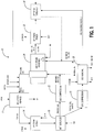
FIG. 1 is a process/schematic diagram of the method/apparatus for sequestering carbon dioxide from a top gas fuel of the present invention; and -
FIG. 2 is a process/schematic diagram of the direct reduction process of the present invention. - Referring to
FIG. 1 , in one exemplary embodiment of the present invention, the apparatus for sequestering carbon dioxide from atop gas fuel 10 inherently includes a vertical shaft-type reduction furnace 12 or the like. In this example, thereduction furnace 12 includes a feed hopper (not illustrated) into which iron oxide pellets, lumps, or compacts are fed at a predetermined rate. The iron oxide pellets, lumps, or compacts descend by gravity into thereduction furnace 12 from the feed hopper through a feed pipe (not illustrated), which also serves as a gas seal pipe. At the bottom of thereduction furnace 12 is a discharge pipe (not illustrated), which further serves as a gas seal pipe. A discharge feeder (not illustrated), such as an electric vibrating feeder or the like, is disposed below the discharge pipe and receives the metallic iron pellets, lumps, or compacts, thereby establishing a system for the gravitational descent of the burden through thereduction furnace 12. - At approximately the midpoint of the
reduction furnace 12 is a bustle and tuyere system (not illustrated), through which the hot reducing gas is introduced at a temperature of between about 700 degrees C and about 1050 degrees C. The hot reducing gas flows upwards through a reduction region of thereduction furnace 12, counter to the flow of the pellets, lumps, or compacts, and exits thereduction furnace 12 through a gas off-take pipe (not illustrated) located at the top of thereduction furnace 12. The feed pipe extends below the gas off-take pipe, this geometric arrangement creating a spent gas disengaging plenum that permits spent gas to disengage from the stock line and flow freely to the gas off-take pipe. The hot reducing gas, in flowing from the bustle and tuyere system to the gas off-take pipe, serves to heat the iron oxide pellets, lumps, or compacts and reduce them to metallic iron pellets, lumps, or compacts (i.e. via direct reduction). The hot reducing gas contains hydrogen, nitrogen, carbon monoxide, carbon dioxide, methane, and water vapor that reduce the iron oxide pellets, lumps, or compacts and produce a spent gas, or top gas, containing carbon dioxide and water vapor. - Referring to
FIG. 2 , the direct reduction processes utilized herein control the reduction conditions, temperatures, and chemistries at the point where the bustle gas enters thereduction furnace 12 by adjusting the carbon dioxide lean gas, natural gas, and oxygen additions to the reducing gas just prior. These direct reduction processes are described generally inU.S. Patent No. 3,748,120 , entitled "Method of Reducing Iron Oxide to Metallic Iron,"U.S. Patent No. 3,749,386 , entitled "Method for Reducing Iron Oxides in a Gaseous Reduction Process,"U.S. Patent No. 3,764,123 , entitled "Apparatus for Reducing Iron Oxide to Metallic Iron,"U.S. Patent No. 3,816,101 , entitled "Method for Reducing Iron Oxides in a Gaseous Reduction Process,"U.S. Patent No. 4,046,557 , entitled "Method for Producing Metallic Iron Particles," andU.S. Patent No. 5,437,708 , entitled "Iron Carbide Production in Shaft Furnace". - The reduction furnace burden acts as a large adiabatic reactor and promotes equilibrium reactions in the zone of the bustle gas injection. As the bustle gas enters the
reduction furnace 12 and passes through the burden, the gas reacts to its equilibrium composition and temperature, which is observed on the burden thermocouples at the upper portion of thereduction furnace 12. - The carburizing reactions are affected by the following reducing gas stream factors:
- 1. Initial reducing gas hydrogen:carbon monoxide ratio;
- 2. Initial reducing gas methane content;
- 3. Initial reducing gas temperature;
- 4. Natural gas addition to reducing gas;
- 5. Oxygen addition to reducing gas;
- 6. Carbon dioxide lean gas addition to reducing gas;
- 7. Final bustle gas reductant:oxidant ratio; and
- 8. Final bustle gas pressure
- Under normal operating conditions, the initial reducing gas quality is closely controlled and becomes the primary stability factor for the direct reduction process. As the reducing gas flows towards the
reduction furnace 12, natural gas is added based on the methane content analysis of the final bustle gas. This provides a stabilizing adjustment for any variation in the methane content of the initial reducing gas, and affects the carburizing potential of the final bustle gas. Oxygen is added to the reducing gas to increase the temperature of the final bustle gas and improve the kinetics of the iron ore reduction process. - Optionally, the operating conditions used include preheating the natural gas addition, reducing gas methane content equal to or less than about 12 percent, and oxygen addition flow/ton equal to or less than about 30 Nm3/t.
- During use of the direct reduction apparatus, gas exits the reducing
gas source 40 and a first sensor performs a gas analyses and measures the temperature of the gas. Natural gas is then mixed with the gas at the natural gas inlet. Oxygen is then mixed with the gas and natural gas mixture at the oxygen inlet, thereby forming the bustle gas. The second sensor performs a gas analysis and measures the temperature of the bustle gas, prior to the bustle gas entering thereduction furnace 12. - Referring again to
FIG. 1 , in accordance with the present invention, the top gas from the gas off-take pipe of thereduction furnace 12 flows through another pipe (not illustrated) to a low-pressure steam boiler 14. This allows for the efficient generation of steam for use elsewhere in the process, such as in the carbon dioxide removal step described in greater detail herein below. Boiler feed water is fed to the low-pressure steam boiler 14 and, as alluded to herein above, the steam generated is recirculated through the process or used elsewhere. - The top gas is then directed to a
wet scrubber 20 that is provided to cool the top gas and remove dust, with a water output. Thewet scrubber 20 may be of any conventional type known to those of ordinary skill in the art, such as a venturi with a packed tower (not illustrated), with the top gas flowing downwards through the venturi and then upwards through the packing counterflow to cooling water. - The top gas exits the
wet scrubber 20 in two streams by the influence of a valve (not illustrated). The first stream represents process gas and the second gas represents top gas fuel (i.e. waste). The ratio of these streams is defined by the available heat in a carbon dioxide andsteam reformer 24 coupled to the first stream, which is typically constant, resulting in an ratio of 1:1 (with the use of recycled carbon dioxide lean gas), 2:1 (without the use of recycled carbon dioxide lean gas). - The process gas from the
wet scrubber 20 is fed to acompressor 22 and compressed to a desired pressure, and then fed to a mixer (not illustrated), where the process gas is mixed with natural gas. This reformer feed gas is then fed into the carbon dioxide andsteam reformer 24. The carbon dioxide andsteam reformer 24 includes fuel-fired burners (not illustrated), producing heated flue gas containing nitrogen, carbon dioxide, and water via combustion and a plurality of catalytic reformer tubes (not illustrated), the later of which utilize reformer feed gas and heat from the combustion to form reducing gas which is fed back into thereduction furnace 12 after the introduction of oxygen, natural gas, and carbon dioxide lean gas, resulting in bustle gas. - The top gas fuel from the
wet scrubber 20 is also fed to acompressor 26 and compressed to a desired pressure, prior to introduction into acarbon dioxide scrubber 28. Thecarbon dioxide scrubber 28 has an input of low-pressure steam, optionally obtained from any of the low-pressure steam boilers top gas fuel 10, and outputs of boiler feed water, sulfur, and carbon dioxide. The boiler feed water may be input into any of the low-pressure steam boilers top gas fuel 10. Another output of thecarbon dioxide scrubber 28 is carbon dioxide lean gas, which when mixed with natural gas becomes, in part, the reformer fuel gas that is fed into the carbon dioxide andsteam reformer 24. - The
carbon dioxide scrubber 28 may include any type of alkanolamine, such as MEA, MDEA, or the like, or any type of hot potassium scrubbing system known to those of ordinary skill in the art. The low-pressure steam is used to regenerate the solution used in thecarbon dioxide scrubber 28, and exits as the boiler feed water. During the carbon dioxide scrubbing process, the sulfur and carbon dioxide are sequestered from the top gas fuel. The top gas fuel minus the sulfur and carbon dioxide exits thecarbon dioxide scrubber 28 as the carbon dioxide lean gas. Again, a portion of the carbon dioxide lean gas is mixed with natural gas to form the reformer fuel gas, and is introduced into the carbon dioxide andsteam reformer 24 via the fuel-fired burners. The remainder of the carbon dioxide lean gas is recycled and mixed with the reducing gas, which is fed back into thereduction furnace 12 after the introduction of oxygen and natural gas, thereby forming the bustle gas. Optionally, later portion of the carbon dioxide lean gas, or the entire stream, is introduced into apreheater 30 prior to mixing with the existing reducing gas or using it as fuel. - In one exemplary embodiment of the present invention, this carbon dioxide lean gas/reducing gas stream ultimately represents about 20 percent of the bustle gas supply to the
reduction furnace 12, while the carbon dioxide and steam reformer reducing gas stream ultimately represents about 80 percent of the bustle gas supply to thereduction furnace 12, although other percentages are contemplated herein. - A flue gas off-take pipe (not illustrated) is provided on the carbon dioxide and
steam reformer 24 for removing the flue gas containing nitrogen, carbon dioxide, and water after combustion. The flue gas flows through one or several heat exchangers, including a low-pressure steam boiler 32. Again, this allows for the efficient generation of steam for use elsewhere in the process, such as in the carbon dioxide removal step described in greater detail herein above. Boiler feed water is fed to the low-pressure steam boiler 32, optionally from thecarbon dioxide scrubber 28, and, as alluded to herein above, the steam generated is recirculated through the process or used elsewhere. The low-pressure steam boiler 32 may thus be coupled to theoptional preheater 30. - Although the present invention has been illustrated and described herein with reference to preferred embodiments and specific examples thereof, it will be readily apparent to those of ordinary skill in the art that other embodiments and examples may perform similar functions and/or achieve like results. The present invention is defined by the appended claims.
Claims (10)
- A method for sequestering carbon dioxide from a top gas fuel, comprising:given a top gas obtained from a reduction furnace (12), wet scrubbed, and divided into a process gas and a top gas fuel:mixing the process gas with a hydrocarbon and feeding a resulting reformer feed gas into a carbon dioxide and steam reformer (24) for reforming the reformer feed gas and forming a reducing gas that is fed back to the reduction furnace; andfeeding at least a portion of the top gas fuel into a carbon dioxide scrubber (28) for removing at least some carbon dioxide from the top gas fuel and forming a carbon dioxide lean gas that becomes, after the addition of a hydrocarbon, a reformer fuel gas which is fed into the carbon dioxide and steam reformer (24), while a portion of the carbon dioxide lean gas is possibly mixed with the reducing gas;wherein a ratio of the process gas to the top gas fuel is defined by the available heat in the carbon dioxide and steam reformer (24) to which the reformer feed gas is fed; that is wherein the ratio of the process gas to the top gas fuel is 1:1 when the carbon dioxide lean gas is utilized for mixing with the reducing gas and is 2:1 when the carbon dioxide lean gas is not utilized for mixing with the reducing gas.
- The method of claim 1, further comprising compressing the process gas and the top gas fuel.
- The method of claim 1, further comprising generating steam from the top gas.
- The method of claim 3, further comprising scrubbing the top gas to remove dust.
- The method of claim 1, further comprising mixing the reducing gas with oxygen and a hydrocarbon to form bustle gas and feeding the bustle gas into a reduction furnace (12).
- The method of claim 1, further comprising preheating the carbon dioxide lean gas before one of mixing it with the reducing gas and using it as fuel.
- The method of claim 1, wherein the carbon dioxide and steam reformer (24) also produces flue gas.
- The method of claim 7, further comprising generating steam from the flue gas.
- The method of claim 8, further comprising using the flue gas to preheat another gas.
- The method of claim 1, wherein the top gas and the reducing gas are associated with a direct reduction process for converting iron oxide to metallic iron.
Applications Claiming Priority (2)
| Application Number | Priority Date | Filing Date | Title |
|---|---|---|---|
| US17099909P | 2009-04-20 | 2009-04-20 | |
| PCT/US2010/031556 WO2010123796A1 (en) | 2009-04-20 | 2010-04-19 | Method and apparatus for sequestering carbon dioxide from a spent gas |
Publications (3)
| Publication Number | Publication Date |
|---|---|
| EP2421941A1 EP2421941A1 (en) | 2012-02-29 |
| EP2421941A4 EP2421941A4 (en) | 2013-01-09 |
| EP2421941B1 true EP2421941B1 (en) | 2017-06-21 |
Family
ID=42980320
Family Applications (1)
| Application Number | Title | Priority Date | Filing Date |
|---|---|---|---|
| EP10767571.2A Active EP2421941B1 (en) | 2009-04-20 | 2010-04-19 | Method for sequestering carbon dioxide from a spent gas |
Country Status (21)
| Country | Link |
|---|---|
| US (1) | US8377417B2 (en) |
| EP (1) | EP2421941B1 (en) |
| JP (1) | JP5465777B2 (en) |
| KR (1) | KR101344940B1 (en) |
| CN (1) | CN102405274B (en) |
| AP (1) | AP3173A (en) |
| AR (1) | AR076337A1 (en) |
| BR (1) | BRPI1014167B1 (en) |
| CA (1) | CA2757479C (en) |
| CL (1) | CL2011002519A1 (en) |
| CO (1) | CO6450657A2 (en) |
| EA (1) | EA022922B1 (en) |
| MA (1) | MA33268B1 (en) |
| MX (1) | MX2011010729A (en) |
| MY (1) | MY155610A (en) |
| NZ (1) | NZ595299A (en) |
| PE (1) | PE20121113A1 (en) |
| TW (1) | TWI407998B (en) |
| UA (1) | UA102748C2 (en) |
| WO (1) | WO2010123796A1 (en) |
| ZA (1) | ZA201106887B (en) |
Families Citing this family (13)
| Publication number | Priority date | Publication date | Assignee | Title |
|---|---|---|---|---|
| AT508523B1 (en) * | 2009-07-31 | 2011-04-15 | Siemens Vai Metals Tech Gmbh | REFORM GAS-BASED REDUCTION PROCESS AND DEVICE WITH DECARBONIZING THE COMBUSTION GAS FOR THE REFORMER |
| WO2011012964A2 (en) * | 2009-07-31 | 2011-02-03 | Hyl Technologies, S.A. De C.V. | Method for producing direct reduced iron with limited co2 emissions |
| JP2012007213A (en) * | 2010-06-25 | 2012-01-12 | Mitsubishi Heavy Ind Ltd | Method for direct reduction ironmaking, and apparatus for production of reducing gas therefor |
| AU2011325859B2 (en) * | 2010-11-03 | 2016-06-30 | Technological Resources Pty. Limited | Production of iron |
| JP5640821B2 (en) * | 2011-03-02 | 2014-12-17 | コニカミノルタ株式会社 | Secondary battery type fuel cell system |
| AT510273B1 (en) * | 2011-03-17 | 2012-03-15 | Siemens Vai Metals Tech Gmbh | METHOD FOR HEATING CONTROL FOR EXHAUST GASES FROM REPRODUCTION OR SYNTHESEGAS PLANTS |
| WO2013064870A1 (en) * | 2011-11-04 | 2013-05-10 | Hyl Technologies, S.A. De C.V. | Process for producing direct reduced iron (dri) with less co2 emissions to the atmosphere |
| EP2738268A1 (en) | 2012-11-29 | 2014-06-04 | Siemens VAI Metals Technologies GmbH | Method for reduction of metal oxides to metallised material in a direct reduction process |
| MX2015009519A (en) * | 2013-02-15 | 2016-02-05 | Midrex Technologies Inc | Method and apparatus for sequestering carbon dioxide from a spent gas. |
| RU2650371C2 (en) * | 2013-02-27 | 2018-04-11 | Хил Текнолоджиз, С.А. Де К.В. | Direct reduction process with improved product quality and process gas efficiency |
| US10065857B2 (en) * | 2013-03-12 | 2018-09-04 | Midrex Technologies, Inc. | Systems and methods for generating carbon dioxide for use as a reforming oxidant in making syngas or reformed gas |
| UA117374C2 (en) * | 2013-07-31 | 2018-07-25 | Мідрекс Текнолоджиз, Інк. | RESTORATION OF IRON TO METAL IRON WITH THE APPLICATION OF COX GAS AND GAS FROM A STEEL FURNITURE WITH OXYGEN SUPPLY |
| EP3034631A1 (en) | 2014-12-17 | 2016-06-22 | Primetals Technologies Austria GmbH | Direct reduction method with gas cooling |
Family Cites Families (54)
| Publication number | Priority date | Publication date | Assignee | Title |
|---|---|---|---|---|
| BE759927A (en) | 1969-12-10 | 1971-06-07 | Midland Ross Corp | METHOD AND APPARATUS FOR THE REDUCTION OF IRON OXIDES IN A REDUCING GASEOUS ATMOSPHERE. |
| US3764123A (en) | 1970-06-29 | 1973-10-09 | Midland Ross Corp | Method of and apparatus for reducing iron oxide to metallic iron |
| US3748120A (en) | 1971-04-15 | 1973-07-24 | Midland Ross Corp | Method of and apparatus for reducing iron oxide to metallic iron |
| US3749386A (en) | 1971-07-01 | 1973-07-31 | Midland Ross Corp | Method and means for reducing iron oxides in a gaseous reduction process |
| US3945944A (en) * | 1971-12-01 | 1976-03-23 | Kang Chia Chen Chu | Catalyst for the production of hydrogen and/or methane |
| US4047935A (en) * | 1974-12-11 | 1977-09-13 | United States Steel Corporation | Process for direct-reduction of iron-ore employing nuclear reactor-powdered catalytic reformer |
| DE2459876B1 (en) * | 1974-12-18 | 1976-06-24 | Thyssen Purofer Gmbh | PLANT FOR THE DIRECT REDUCTION OF IRON ORES |
| US4046557A (en) | 1975-09-08 | 1977-09-06 | Midrex Corporation | Method for producing metallic iron particles |
| US4529440A (en) * | 1978-07-21 | 1985-07-16 | Jordan Robert K | Chemicals from coal |
| US4201571A (en) * | 1978-08-15 | 1980-05-06 | Midrex Corporation | Method for the direct reduction of iron and production of fuel gas using gas from coal |
| US4216011A (en) * | 1979-04-23 | 1980-08-05 | Hylsa, S.A. | Method and apparatus for the secondary gaseous reduction of metal ores |
| US4363654A (en) * | 1980-04-08 | 1982-12-14 | Geoffrey Frederick | Production of reducing gas for furnace injection |
| DE3024977A1 (en) * | 1980-07-02 | 1982-01-28 | Klöckner-Humboldt-Deutz AG, 5000 Köln | METHOD FOR PRODUCING REACTION GAS |
| US4336063A (en) * | 1980-09-29 | 1982-06-22 | Hylsa, S.A. | Method and apparatus for the gaseous reduction of iron ore to sponge iron |
| GB2084610B (en) * | 1980-09-29 | 1983-10-12 | Woods Jack L | Anodic oxidation of aluminium and aluminum alloys |
| US4428772A (en) * | 1981-12-02 | 1984-01-31 | Hylsa, S.A. | Method for reducing metal ore |
| US4553742A (en) * | 1983-12-01 | 1985-11-19 | Midrex International Bv Rotterdam, Zurich Branch | Apparatus for generating a reducing gas |
| US4584016A (en) * | 1982-03-23 | 1986-04-22 | Hylsa, S.A. | Method for controlling metallization and carburization in the reduction of metal ores to sponge iron |
| US4880458A (en) * | 1983-05-16 | 1989-11-14 | Hylsa, S.A. De C.V. | Start-up method for a direct reduction process without an external reformer |
| US4591380A (en) * | 1983-12-01 | 1986-05-27 | Midrex International B.V. Rotterdam, Zurich Branch | Method of generating a reducing gas |
| US4734128A (en) * | 1985-09-23 | 1988-03-29 | Hylsa, S.A. | Direct reduction reactor with hot discharge |
| US4897113A (en) * | 1985-09-23 | 1990-01-30 | Hylsa, S.A. | Direct reduction process in reactor with hot discharge |
| US4685964A (en) * | 1985-10-03 | 1987-08-11 | Midrex International B.V. Rotterdam | Method and apparatus for producing molten iron using coal |
| US4900356A (en) * | 1986-04-17 | 1990-02-13 | Midrex International B.V. | Process and apparatus for producing metallized pellets and scrubbing spent reducing gas |
| US4834792A (en) * | 1986-08-21 | 1989-05-30 | Hylsa S.A. De C.V. | Method for producing hot sponge iron by introducing hydrocarbon for carburizing into reduction zone |
| US4756750A (en) * | 1987-04-27 | 1988-07-12 | Air Products And Chemicals, Inc. | Process for the direct reduction of iron ore |
| US5064467A (en) * | 1987-11-02 | 1991-11-12 | C.V.G. Siderurgica Del Orinoco, C.A. | Method and apparatus for the direct reduction of iron |
| US4880459A (en) * | 1988-06-27 | 1989-11-14 | T.C., Inc. | Method of and apparatus for reducing iron oxide to metallic iron |
| US5445363A (en) * | 1990-01-09 | 1995-08-29 | Hylsa S.A. De C.V. | Apparatus for the pneumatic transport of large iron-bearing particles |
| US5082251A (en) * | 1990-03-30 | 1992-01-21 | Fior De Venezuela | Plant and process for fluidized bed reduction of ore |
| US5078787A (en) * | 1990-06-01 | 1992-01-07 | Hylsa S.A. De C.V. | Method and apparatus for the production of hot direct reduced iron |
| US6197088B1 (en) * | 1992-10-06 | 2001-03-06 | Bechtel Group, Inc. | Producing liquid iron having a low sulfur content |
| US5958107A (en) * | 1993-12-15 | 1999-09-28 | Bechtel Croup, Inc. | Shift conversion for the preparation of reducing gas |
| US5618032A (en) * | 1994-05-04 | 1997-04-08 | Midrex International B.V. Rotterdam, Zurich Branch | Shaft furnace for production of iron carbide |
| US5437708A (en) | 1994-05-04 | 1995-08-01 | Midrex International B.V. Rotterdam, Zurich Branch | Iron carbide production in shaft furnace |
| US5437706A (en) * | 1994-06-10 | 1995-08-01 | Borealis Technical Incorporated Limited | Method for operating a blast furnace |
| US5752995A (en) * | 1994-06-30 | 1998-05-19 | Kang; Chia-Chen Chu | Catalyst and process for the production of hydrogen and/or methane |
| US5676732A (en) * | 1995-09-15 | 1997-10-14 | Hylsa, S.A. De C.V. | Method for producing direct reduced iron utilizing a reducing gas with a high content of carbon monoxide |
| US5582029A (en) * | 1995-10-04 | 1996-12-10 | Air Products And Chemicals, Inc. | Use of nitrogen from an air separation plant in carbon dioxide removal from a feed gas to a further process |
| UA42803C2 (en) * | 1995-10-10 | 2001-11-15 | Фоест-Альпіне Індустріанлагенбау Гмбх | METHOD OF DIRECT RESTORATION OF FINE GRAIN MATERIAL IN THE FORM OF PARTICLES CONTAINING IRON OXIDE, AND INSTALLATION FOR CARRYING OUT THIS METHOD |
| US6395056B1 (en) * | 1996-09-25 | 2002-05-28 | Hylsa S.A. De C.V. | Method for the heat treatment of iron ore lumps in a reduction system |
| US5858057A (en) * | 1996-09-25 | 1999-01-12 | Hylsa S.A. De C.V. | Method for producing direct reduced iron with a controlled amount of carbon |
| US6039916A (en) * | 1996-09-25 | 2000-03-21 | Hylsa S.A. De C.V. | Apparatus for producing direct reduced iron with a controlled amount of carbon |
| US6149859A (en) * | 1997-11-03 | 2000-11-21 | Texaco Inc. | Gasification plant for direct reduction reactors |
| US6033456A (en) * | 1998-02-06 | 2000-03-07 | Texaco Inc. | Integration of partial oxidation process and direct reduction reaction process |
| US6027545A (en) * | 1998-02-20 | 2000-02-22 | Hylsa, S.A. De C.V. | Method and apparatus for producing direct reduced iron with improved reducing gas utilization |
| US6183535B1 (en) * | 1998-10-16 | 2001-02-06 | Hylsa, S.A. De C.V. | Method for increasing the capacity of a direct reduced iron plant without increasing its reformer capacity |
| US6045602A (en) * | 1998-10-28 | 2000-04-04 | Praxair Technology, Inc. | Method for integrating a blast furnace and a direct reduction reactor using cryogenic rectification |
| US6648942B2 (en) * | 2001-01-26 | 2003-11-18 | Midrex International B.V. Rotterdam, Zurich Branch | Method of direct iron-making / steel-making via gas or coal-based direct reduction and apparatus |
| US6562103B2 (en) * | 2001-07-27 | 2003-05-13 | Uop Llc | Process for removal of carbon dioxide for use in producing direct reduced iron |
| JP2004309067A (en) * | 2003-04-09 | 2004-11-04 | Nippon Steel Corp | Method of using blast furnace gas |
| MXPA05012242A (en) * | 2003-05-15 | 2006-02-08 | Hylsa Sa | Method and apparatus for improved use of primary energy sources in integrated steel plants. |
| JP4515975B2 (en) * | 2005-06-30 | 2010-08-04 | 株式会社日立製作所 | System and method using reformed gas |
| US7608129B2 (en) | 2006-04-24 | 2009-10-27 | Hyl Technologies S.A. De C.V. | Method and apparatus for producing direct reduced iron |
-
2010
- 2010-04-19 MY MYPI2011004931A patent/MY155610A/en unknown
- 2010-04-19 JP JP2012505993A patent/JP5465777B2/en not_active Expired - Fee Related
- 2010-04-19 EA EA201171260A patent/EA022922B1/en not_active IP Right Cessation
- 2010-04-19 US US12/762,618 patent/US8377417B2/en active Active
- 2010-04-19 BR BRPI1014167-7A patent/BRPI1014167B1/en not_active IP Right Cessation
- 2010-04-19 NZ NZ59529910A patent/NZ595299A/en not_active IP Right Cessation
- 2010-04-19 PE PE2011001811A patent/PE20121113A1/en not_active Application Discontinuation
- 2010-04-19 AP AP2011005926A patent/AP3173A/en active
- 2010-04-19 UA UAA201113529A patent/UA102748C2/en unknown
- 2010-04-19 WO PCT/US2010/031556 patent/WO2010123796A1/en active Application Filing
- 2010-04-19 MX MX2011010729A patent/MX2011010729A/en active IP Right Grant
- 2010-04-19 MA MA34341A patent/MA33268B1/en unknown
- 2010-04-19 KR KR1020117024481A patent/KR101344940B1/en not_active IP Right Cessation
- 2010-04-19 EP EP10767571.2A patent/EP2421941B1/en active Active
- 2010-04-19 CA CA2757479A patent/CA2757479C/en not_active Expired - Fee Related
- 2010-04-19 CN CN201080017230.9A patent/CN102405274B/en not_active Expired - Fee Related
- 2010-04-20 TW TW99112305A patent/TWI407998B/en active
- 2010-04-20 AR ARP100101298 patent/AR076337A1/en active IP Right Grant
-
2011
- 2011-09-21 ZA ZA2011/06887A patent/ZA201106887B/en unknown
- 2011-10-07 CL CL2011002519A patent/CL2011002519A1/en unknown
- 2011-10-20 CO CO11140523A patent/CO6450657A2/en not_active Application Discontinuation
Also Published As
| Publication number | Publication date |
|---|---|
| MX2011010729A (en) | 2011-10-24 |
| WO2010123796A1 (en) | 2010-10-28 |
| BRPI1014167B1 (en) | 2018-07-31 |
| UA102748C2 (en) | 2013-08-12 |
| NZ595299A (en) | 2013-05-31 |
| TWI407998B (en) | 2013-09-11 |
| US20100264374A1 (en) | 2010-10-21 |
| AR076337A1 (en) | 2011-06-01 |
| CA2757479C (en) | 2016-03-22 |
| CL2011002519A1 (en) | 2012-06-22 |
| CO6450657A2 (en) | 2012-05-31 |
| EA022922B1 (en) | 2016-03-31 |
| MY155610A (en) | 2015-11-13 |
| KR101344940B1 (en) | 2013-12-27 |
| JP2012524233A (en) | 2012-10-11 |
| PE20121113A1 (en) | 2012-08-17 |
| TW201039911A (en) | 2010-11-16 |
| AP2011005926A0 (en) | 2011-10-31 |
| EP2421941A1 (en) | 2012-02-29 |
| CA2757479A1 (en) | 2010-10-28 |
| EP2421941A4 (en) | 2013-01-09 |
| MA33268B1 (en) | 2012-05-02 |
| US8377417B2 (en) | 2013-02-19 |
| EA201171260A1 (en) | 2012-03-30 |
| KR20120008503A (en) | 2012-01-30 |
| CN102405274B (en) | 2014-03-12 |
| JP5465777B2 (en) | 2014-04-09 |
| AP3173A (en) | 2015-03-31 |
| ZA201106887B (en) | 2012-06-27 |
| CN102405274A (en) | 2012-04-04 |
Similar Documents
| Publication | Publication Date | Title |
|---|---|---|
| EP2421941B1 (en) | Method for sequestering carbon dioxide from a spent gas | |
| EP2798293B1 (en) | Method of producing molten iron in a blast furnace with top-gas recycle | |
| EP3027779B1 (en) | Reducing iron oxide to metallic iron using natural gas | |
| EP3027778B1 (en) | Reduction of iron oxide to metallic iron using coke oven gas and oxygen steelmaking furnace gas | |
| US9938595B2 (en) | Direct reduction process with improved product quality and process gas efficiency | |
| US8771638B2 (en) | Method and apparatus for sequestering carbon dioxide from a spent gas | |
| TW201915174A (en) | Method for producing hot synthesis gas, in particular for use in blast furnace operation | |
| TW202100756A (en) | Method for operating a blast furnace | |
| TWI576313B (en) | Method and apparatus for sequestering carbon dioxide from a spent gas | |
| CN113825845B (en) | Method for operating a metallurgical furnace | |
| JP7192845B2 (en) | Blast Furnace Operation Method and Blast Furnace Incidental Equipment | |
| JP7131697B2 (en) | Blast Furnace Operation Method and Blast Furnace Incidental Equipment | |
| US20230340628A1 (en) | Method for operating a blast furnace installation | |
| US20220372587A1 (en) | Direct reduced iron system and method using synthetic combustion air | |
| EA046149B1 (en) | METHOD OF OPERATING THE BLAST FURNACE INSTALLATION | |
| EA045314B1 (en) | METHOD OF OPERATING THE BLAST FURNACE INSTALLATION | |
| JP2022505386A (en) | Carbon dioxide emission reduction type molten iron manufacturing equipment and its manufacturing method |
Legal Events
| Date | Code | Title | Description |
|---|---|---|---|
| PUAI | Public reference made under article 153(3) epc to a published international application that has entered the european phase |
Free format text: ORIGINAL CODE: 0009012 |
|
| 17P | Request for examination filed |
Effective date: 20110916 |
|
| AK | Designated contracting states |
Kind code of ref document: A1 Designated state(s): AT BE BG CH CY CZ DE DK EE ES FI FR GB GR HR HU IE IS IT LI LT LU LV MC MK MT NL NO PL PT RO SE SI SK SM TR |
|
| DAX | Request for extension of the european patent (deleted) | ||
| A4 | Supplementary search report drawn up and despatched |
Effective date: 20121207 |
|
| RIC1 | Information provided on ipc code assigned before grant |
Ipc: B01D 53/14 20060101ALI20121203BHEP Ipc: C21B 13/00 20060101ALI20121203BHEP Ipc: C10L 3/00 20060101AFI20121203BHEP |
|
| 17Q | First examination report despatched |
Effective date: 20140415 |
|
| GRAP | Despatch of communication of intention to grant a patent |
Free format text: ORIGINAL CODE: EPIDOSNIGR1 |
|
| INTG | Intention to grant announced |
Effective date: 20170118 |
|
| GRAS | Grant fee paid |
Free format text: ORIGINAL CODE: EPIDOSNIGR3 |
|
| GRAA | (expected) grant |
Free format text: ORIGINAL CODE: 0009210 |
|
| AK | Designated contracting states |
Kind code of ref document: B1 Designated state(s): AT BE BG CH CY CZ DE DK EE ES FI FR GB GR HR HU IE IS IT LI LT LU LV MC MK MT NL NO PL PT RO SE SI SK SM TR |
|
| REG | Reference to a national code |
Ref country code: GB Ref legal event code: FG4D |
|
| REG | Reference to a national code |
Ref country code: CH Ref legal event code: EP |
|
| REG | Reference to a national code |
Ref country code: IE Ref legal event code: FG4D |
|
| REG | Reference to a national code |
Ref country code: AT Ref legal event code: REF Ref document number: 902945 Country of ref document: AT Kind code of ref document: T Effective date: 20170715 |
|
| REG | Reference to a national code |
Ref country code: DE Ref legal event code: R096 Ref document number: 602010043142 Country of ref document: DE |
|
| REG | Reference to a national code |
Ref country code: NL Ref legal event code: MP Effective date: 20170621 |
|
| PG25 | Lapsed in a contracting state [announced via postgrant information from national office to epo] |
Ref country code: NO Free format text: LAPSE BECAUSE OF FAILURE TO SUBMIT A TRANSLATION OF THE DESCRIPTION OR TO PAY THE FEE WITHIN THE PRESCRIBED TIME-LIMIT Effective date: 20170921 Ref country code: HR Free format text: LAPSE BECAUSE OF FAILURE TO SUBMIT A TRANSLATION OF THE DESCRIPTION OR TO PAY THE FEE WITHIN THE PRESCRIBED TIME-LIMIT Effective date: 20170621 Ref country code: GR Free format text: LAPSE BECAUSE OF FAILURE TO SUBMIT A TRANSLATION OF THE DESCRIPTION OR TO PAY THE FEE WITHIN THE PRESCRIBED TIME-LIMIT Effective date: 20170922 Ref country code: FI Free format text: LAPSE BECAUSE OF FAILURE TO SUBMIT A TRANSLATION OF THE DESCRIPTION OR TO PAY THE FEE WITHIN THE PRESCRIBED TIME-LIMIT Effective date: 20170621 Ref country code: LT Free format text: LAPSE BECAUSE OF FAILURE TO SUBMIT A TRANSLATION OF THE DESCRIPTION OR TO PAY THE FEE WITHIN THE PRESCRIBED TIME-LIMIT Effective date: 20170621 |
|
| REG | Reference to a national code |
Ref country code: LT Ref legal event code: MG4D |
|
| REG | Reference to a national code |
Ref country code: AT Ref legal event code: MK05 Ref document number: 902945 Country of ref document: AT Kind code of ref document: T Effective date: 20170621 |
|
| PG25 | Lapsed in a contracting state [announced via postgrant information from national office to epo] |
Ref country code: LV Free format text: LAPSE BECAUSE OF FAILURE TO SUBMIT A TRANSLATION OF THE DESCRIPTION OR TO PAY THE FEE WITHIN THE PRESCRIBED TIME-LIMIT Effective date: 20170621 Ref country code: NL Free format text: LAPSE BECAUSE OF FAILURE TO SUBMIT A TRANSLATION OF THE DESCRIPTION OR TO PAY THE FEE WITHIN THE PRESCRIBED TIME-LIMIT Effective date: 20170621 Ref country code: SE Free format text: LAPSE BECAUSE OF FAILURE TO SUBMIT A TRANSLATION OF THE DESCRIPTION OR TO PAY THE FEE WITHIN THE PRESCRIBED TIME-LIMIT Effective date: 20170621 Ref country code: BG Free format text: LAPSE BECAUSE OF FAILURE TO SUBMIT A TRANSLATION OF THE DESCRIPTION OR TO PAY THE FEE WITHIN THE PRESCRIBED TIME-LIMIT Effective date: 20170921 |
|
| PG25 | Lapsed in a contracting state [announced via postgrant information from national office to epo] |
Ref country code: CZ Free format text: LAPSE BECAUSE OF FAILURE TO SUBMIT A TRANSLATION OF THE DESCRIPTION OR TO PAY THE FEE WITHIN THE PRESCRIBED TIME-LIMIT Effective date: 20170621 Ref country code: RO Free format text: LAPSE BECAUSE OF FAILURE TO SUBMIT A TRANSLATION OF THE DESCRIPTION OR TO PAY THE FEE WITHIN THE PRESCRIBED TIME-LIMIT Effective date: 20170621 Ref country code: AT Free format text: LAPSE BECAUSE OF FAILURE TO SUBMIT A TRANSLATION OF THE DESCRIPTION OR TO PAY THE FEE WITHIN THE PRESCRIBED TIME-LIMIT Effective date: 20170621 Ref country code: EE Free format text: LAPSE BECAUSE OF FAILURE TO SUBMIT A TRANSLATION OF THE DESCRIPTION OR TO PAY THE FEE WITHIN THE PRESCRIBED TIME-LIMIT Effective date: 20170621 Ref country code: SK Free format text: LAPSE BECAUSE OF FAILURE TO SUBMIT A TRANSLATION OF THE DESCRIPTION OR TO PAY THE FEE WITHIN THE PRESCRIBED TIME-LIMIT Effective date: 20170621 |
|
| PG25 | Lapsed in a contracting state [announced via postgrant information from national office to epo] |
Ref country code: PL Free format text: LAPSE BECAUSE OF FAILURE TO SUBMIT A TRANSLATION OF THE DESCRIPTION OR TO PAY THE FEE WITHIN THE PRESCRIBED TIME-LIMIT Effective date: 20170621 Ref country code: IS Free format text: LAPSE BECAUSE OF FAILURE TO SUBMIT A TRANSLATION OF THE DESCRIPTION OR TO PAY THE FEE WITHIN THE PRESCRIBED TIME-LIMIT Effective date: 20171021 Ref country code: SM Free format text: LAPSE BECAUSE OF FAILURE TO SUBMIT A TRANSLATION OF THE DESCRIPTION OR TO PAY THE FEE WITHIN THE PRESCRIBED TIME-LIMIT Effective date: 20170621 Ref country code: ES Free format text: LAPSE BECAUSE OF FAILURE TO SUBMIT A TRANSLATION OF THE DESCRIPTION OR TO PAY THE FEE WITHIN THE PRESCRIBED TIME-LIMIT Effective date: 20170621 |
|
| REG | Reference to a national code |
Ref country code: DE Ref legal event code: R097 Ref document number: 602010043142 Country of ref document: DE |
|
| PLBE | No opposition filed within time limit |
Free format text: ORIGINAL CODE: 0009261 |
|
| STAA | Information on the status of an ep patent application or granted ep patent |
Free format text: STATUS: NO OPPOSITION FILED WITHIN TIME LIMIT |
|
| PG25 | Lapsed in a contracting state [announced via postgrant information from national office to epo] |
Ref country code: DK Free format text: LAPSE BECAUSE OF FAILURE TO SUBMIT A TRANSLATION OF THE DESCRIPTION OR TO PAY THE FEE WITHIN THE PRESCRIBED TIME-LIMIT Effective date: 20170621 |
|
| 26N | No opposition filed |
Effective date: 20180322 |
|
| PG25 | Lapsed in a contracting state [announced via postgrant information from national office to epo] |
Ref country code: SI Free format text: LAPSE BECAUSE OF FAILURE TO SUBMIT A TRANSLATION OF THE DESCRIPTION OR TO PAY THE FEE WITHIN THE PRESCRIBED TIME-LIMIT Effective date: 20170621 |
|
| PG25 | Lapsed in a contracting state [announced via postgrant information from national office to epo] |
Ref country code: MC Free format text: LAPSE BECAUSE OF FAILURE TO SUBMIT A TRANSLATION OF THE DESCRIPTION OR TO PAY THE FEE WITHIN THE PRESCRIBED TIME-LIMIT Effective date: 20170621 |
|
| REG | Reference to a national code |
Ref country code: CH Ref legal event code: PL |
|
| REG | Reference to a national code |
Ref country code: BE Ref legal event code: MM Effective date: 20180430 |
|
| GBPC | Gb: european patent ceased through non-payment of renewal fee |
Effective date: 20180419 |
|
| REG | Reference to a national code |
Ref country code: IE Ref legal event code: MM4A |
|
| PG25 | Lapsed in a contracting state [announced via postgrant information from national office to epo] |
Ref country code: LU Free format text: LAPSE BECAUSE OF NON-PAYMENT OF DUE FEES Effective date: 20180419 |
|
| PG25 | Lapsed in a contracting state [announced via postgrant information from national office to epo] |
Ref country code: GB Free format text: LAPSE BECAUSE OF NON-PAYMENT OF DUE FEES Effective date: 20180419 Ref country code: BE Free format text: LAPSE BECAUSE OF NON-PAYMENT OF DUE FEES Effective date: 20180430 Ref country code: CH Free format text: LAPSE BECAUSE OF NON-PAYMENT OF DUE FEES Effective date: 20180430 Ref country code: LI Free format text: LAPSE BECAUSE OF NON-PAYMENT OF DUE FEES Effective date: 20180430 |
|
| PG25 | Lapsed in a contracting state [announced via postgrant information from national office to epo] |
Ref country code: FR Free format text: LAPSE BECAUSE OF NON-PAYMENT OF DUE FEES Effective date: 20180430 Ref country code: IE Free format text: LAPSE BECAUSE OF NON-PAYMENT OF DUE FEES Effective date: 20180419 |
|
| PG25 | Lapsed in a contracting state [announced via postgrant information from national office to epo] |
Ref country code: MT Free format text: LAPSE BECAUSE OF NON-PAYMENT OF DUE FEES Effective date: 20180419 |
|
| PG25 | Lapsed in a contracting state [announced via postgrant information from national office to epo] |
Ref country code: HU Free format text: LAPSE BECAUSE OF FAILURE TO SUBMIT A TRANSLATION OF THE DESCRIPTION OR TO PAY THE FEE WITHIN THE PRESCRIBED TIME-LIMIT; INVALID AB INITIO Effective date: 20100419 Ref country code: PT Free format text: LAPSE BECAUSE OF FAILURE TO SUBMIT A TRANSLATION OF THE DESCRIPTION OR TO PAY THE FEE WITHIN THE PRESCRIBED TIME-LIMIT Effective date: 20170621 |
|
| PG25 | Lapsed in a contracting state [announced via postgrant information from national office to epo] |
Ref country code: CY Free format text: LAPSE BECAUSE OF FAILURE TO SUBMIT A TRANSLATION OF THE DESCRIPTION OR TO PAY THE FEE WITHIN THE PRESCRIBED TIME-LIMIT Effective date: 20170621 Ref country code: MK Free format text: LAPSE BECAUSE OF NON-PAYMENT OF DUE FEES Effective date: 20170621 |
|
| P01 | Opt-out of the competence of the unified patent court (upc) registered |
Effective date: 20230531 |
|
| PGFP | Annual fee paid to national office [announced via postgrant information from national office to epo] |
Ref country code: IT Payment date: 20230420 Year of fee payment: 14 Ref country code: DE Payment date: 20230320 Year of fee payment: 14 |
|
| PGFP | Annual fee paid to national office [announced via postgrant information from national office to epo] |
Ref country code: TR Payment date: 20230417 Year of fee payment: 14 |