EP2420450A1 - Apparatus for filling a product into a container under aseptic conditions - Google Patents
Apparatus for filling a product into a container under aseptic conditions Download PDFInfo
- Publication number
- EP2420450A1 EP2420450A1 EP10173102A EP10173102A EP2420450A1 EP 2420450 A1 EP2420450 A1 EP 2420450A1 EP 10173102 A EP10173102 A EP 10173102A EP 10173102 A EP10173102 A EP 10173102A EP 2420450 A1 EP2420450 A1 EP 2420450A1
- Authority
- EP
- European Patent Office
- Prior art keywords
- container
- station
- filling
- containers
- carriage
- Prior art date
- Legal status (The legal status is an assumption and is not a legal conclusion. Google has not performed a legal analysis and makes no representation as to the accuracy of the status listed.)
- Withdrawn
Links
Images


Classifications
-
- B—PERFORMING OPERATIONS; TRANSPORTING
- B65—CONVEYING; PACKING; STORING; HANDLING THIN OR FILAMENTARY MATERIAL
- B65B—MACHINES, APPARATUS OR DEVICES FOR, OR METHODS OF, PACKAGING ARTICLES OR MATERIALS; UNPACKING
- B65B55/00—Preserving, protecting or purifying packages or package contents in association with packaging
- B65B55/02—Sterilising, e.g. of complete packages
- B65B55/025—Packaging in aseptic tunnels
-
- B—PERFORMING OPERATIONS; TRANSPORTING
- B65—CONVEYING; PACKING; STORING; HANDLING THIN OR FILAMENTARY MATERIAL
- B65B—MACHINES, APPARATUS OR DEVICES FOR, OR METHODS OF, PACKAGING ARTICLES OR MATERIALS; UNPACKING
- B65B3/00—Packaging plastic material, semiliquids, liquids or mixed solids and liquids, in individual containers or receptacles, e.g. bags, sacks, boxes, cartons, cans, or jars
- B65B3/003—Filling medical containers such as ampoules, vials, syringes or the like
-
- B—PERFORMING OPERATIONS; TRANSPORTING
- B65—CONVEYING; PACKING; STORING; HANDLING THIN OR FILAMENTARY MATERIAL
- B65B—MACHINES, APPARATUS OR DEVICES FOR, OR METHODS OF, PACKAGING ARTICLES OR MATERIALS; UNPACKING
- B65B3/00—Packaging plastic material, semiliquids, liquids or mixed solids and liquids, in individual containers or receptacles, e.g. bags, sacks, boxes, cartons, cans, or jars
- B65B3/26—Methods or devices for controlling the quantity of the material fed or filled
- B65B3/28—Methods or devices for controlling the quantity of the material fed or filled by weighing
-
- B—PERFORMING OPERATIONS; TRANSPORTING
- B65—CONVEYING; PACKING; STORING; HANDLING THIN OR FILAMENTARY MATERIAL
- B65B—MACHINES, APPARATUS OR DEVICES FOR, OR METHODS OF, PACKAGING ARTICLES OR MATERIALS; UNPACKING
- B65B43/00—Forming, feeding, opening or setting-up containers or receptacles in association with packaging
- B65B43/42—Feeding or positioning bags, boxes, or cartons in the distended, opened, or set-up state; Feeding preformed rigid containers, e.g. tins, capsules, glass tubes, glasses, to the packaging position; Locating containers or receptacles at the filling position; Supporting containers or receptacles during the filling operation
- B65B43/52—Feeding or positioning bags, boxes, or cartons in the distended, opened, or set-up state; Feeding preformed rigid containers, e.g. tins, capsules, glass tubes, glasses, to the packaging position; Locating containers or receptacles at the filling position; Supporting containers or receptacles during the filling operation using roller-ways or endless conveyors
-
- B—PERFORMING OPERATIONS; TRANSPORTING
- B65—CONVEYING; PACKING; STORING; HANDLING THIN OR FILAMENTARY MATERIAL
- B65B—MACHINES, APPARATUS OR DEVICES FOR, OR METHODS OF, PACKAGING ARTICLES OR MATERIALS; UNPACKING
- B65B55/00—Preserving, protecting or purifying packages or package contents in association with packaging
- B65B55/02—Sterilising, e.g. of complete packages
- B65B55/027—Packaging in aseptic chambers
-
- F—MECHANICAL ENGINEERING; LIGHTING; HEATING; WEAPONS; BLASTING
- F26—DRYING
- F26B—DRYING SOLID MATERIALS OR OBJECTS BY REMOVING LIQUID THEREFROM
- F26B15/00—Machines or apparatus for drying objects with progressive movement; Machines or apparatus with progressive movement for drying batches of material in compact form
- F26B15/02—Machines or apparatus for drying objects with progressive movement; Machines or apparatus with progressive movement for drying batches of material in compact form with movement in the whole or part of a circle
- F26B15/04—Machines or apparatus for drying objects with progressive movement; Machines or apparatus with progressive movement for drying batches of material in compact form with movement in the whole or part of a circle in a horizontal plane
-
- B—PERFORMING OPERATIONS; TRANSPORTING
- B08—CLEANING
- B08B—CLEANING IN GENERAL; PREVENTION OF FOULING IN GENERAL
- B08B15/00—Preventing escape of dirt or fumes from the area where they are produced; Collecting or removing dirt or fumes from that area
- B08B15/02—Preventing escape of dirt or fumes from the area where they are produced; Collecting or removing dirt or fumes from that area using chambers or hoods covering the area
-
- B—PERFORMING OPERATIONS; TRANSPORTING
- B65—CONVEYING; PACKING; STORING; HANDLING THIN OR FILAMENTARY MATERIAL
- B65B—MACHINES, APPARATUS OR DEVICES FOR, OR METHODS OF, PACKAGING ARTICLES OR MATERIALS; UNPACKING
- B65B2210/00—Specific aspects of the packaging machine
- B65B2210/06—Sterilising or cleaning machinery or conduits
-
- B—PERFORMING OPERATIONS; TRANSPORTING
- B65—CONVEYING; PACKING; STORING; HANDLING THIN OR FILAMENTARY MATERIAL
- B65B—MACHINES, APPARATUS OR DEVICES FOR, OR METHODS OF, PACKAGING ARTICLES OR MATERIALS; UNPACKING
- B65B31/00—Packaging articles or materials under special atmospheric or gaseous conditions; Adding propellants to aerosol containers
- B65B31/02—Filling, closing, or filling and closing, containers or wrappers in chambers maintained under vacuum or superatmospheric pressure or containing a special atmosphere, e.g. of inert gas
- B65B31/025—Filling, closing, or filling and closing, containers or wrappers in chambers maintained under vacuum or superatmospheric pressure or containing a special atmosphere, e.g. of inert gas specially adapted for rigid or semi-rigid containers
- B65B31/027—Filling, closing, or filling and closing, containers or wrappers in chambers maintained under vacuum or superatmospheric pressure or containing a special atmosphere, e.g. of inert gas specially adapted for rigid or semi-rigid containers closed by a stopper
-
- F—MECHANICAL ENGINEERING; LIGHTING; HEATING; WEAPONS; BLASTING
- F26—DRYING
- F26B—DRYING SOLID MATERIALS OR OBJECTS BY REMOVING LIQUID THEREFROM
- F26B5/00—Drying solid materials or objects by processes not involving the application of heat
- F26B5/04—Drying solid materials or objects by processes not involving the application of heat by evaporation or sublimation of moisture under reduced pressure, e.g. in a vacuum
- F26B5/06—Drying solid materials or objects by processes not involving the application of heat by evaporation or sublimation of moisture under reduced pressure, e.g. in a vacuum the process involving freezing
Definitions
- the present invention relates to an apparatus for filling a product, in particular a medicament, under aseptic conditions into a container, said apparatus comprising an upper compartment separated from a lower compartment by a liquid impermeable wall, wherein said apparatus further comprises:
- the filling of a medicament into a container is in practice typically executed in an aseptic environment.
- Aseptic environments are organized in classes, in which each further class refers to a higher sterility of the environment.
- An aseptic environment established in an apparatus prevents the medicament and container being handled in the apparatus from being contaminated, thus it prevents the penetration of contaminants from the environment into the inside of the apparatus.
- such apparatus for filling a medicament comprises an aseptic compartment, referred to as the upper compartment, where the containers are handled and manipulated, and which compartment is provided to comply with the standards laid down in the class of sterility that corresponds to the predetermined requirements for filling the medicament.
- the sterile compartment is furthermore formed so that it is cleanable with a cleaning liquid.
- the machinery In order to prevent this liquid from reaching the machinery of the stations, being the driving and controlling means provided for driving and controlling the manipulating and handling means, the machinery is located in another compartment which is separated form the sterile compartment by a liquid impermeable wall.
- the machinery comprising for example an electromotor and a plurality of electrically driven actuators, is typically less waterproof than the handling and manipulating means. Housing the driving and controlling means in compartments separate from the handling and manipulating means results in that the driving and controlling means can substantially be held dry while the sterile compartment is flushed with liquid for cleaning purposes. Furthermore in such configuration, there is no need to keep the machinery sterile, however there is a need to prevent the machinery from being contaminated by hazardous products which may be filled into containers in the upper compartment.
- one or a plurality of operational connections are established through the liquid impermeable wall between on the one hand the driving and controlling means in the lower compartment and on the other hand the handling and manipulating means in the upper compartment. These operational connections transmit movements, electrical signals and currents, products from the lower compartment to the upper compartment and vice versa.
- a drawback of such apparatus is that the operational connections, particularly the operational connections which transmit movements from the lower to the upper compartment, are not formed to guarantee that contaminants can not move from the upper to the lower compartment and vice versa. Therefore, the sterility of the upper compartment can not be fully guaranteed.
- a hazardous product being a product that can harm for example a human being
- not only contamination from the lower compartment to the upper compartment is to be prevented for sterility purposes, but also the contamination of the lower compartment with hazardous products should be prevented. If such contamination can not be prevented, the safety of a human being working on the machinery can not be guaranteed, since hazardous products may have reached the lower compartment via the operational connections.
- the apparatus according to the present invention is characterised in that said conveying means is formed by a magnetic conveyor, and said at least one operational connection consists of one or a plurality of the following:
- the very specific selection of operational connections in combination with the conveying means being formed by a magnetic conveyor provides in a solution whereby the separation between lower compartment and upper compartment can be fully guaranteed.
- the static, dynamic and/or wireless connections are each configured to form a barrier for contaminants.
- the static connection is solidly sealed to the liquid impermeable wall
- the dynamic connection is solidly sealed to the liquid impermeable wall through the intermediary of a flexible element
- no opening is formed so that no sealing is required.
- connection means and the magnetic conveyor provides in a significant synergetic effect, which proves to be very valuable in aseptic filling machines.
- the dynamic connections are sealed by providing a sliding seal between the wall and the moveable element, for example an O-ring, which is a type of seal utilised in rotating equipment, such as pumps and compressors.
- O-ring is a type of seal utilised in rotating equipment, such as pumps and compressors.
- O-rings or equivalent means are used to prevent leakage. Applying such O-rings in the apparatus for sealing the dynamic connections will indeed prevent the majority of the liquid to flow from the upper into the lower compartment.
- the present invention explicitly claiming an element whether or not via an intermediary piece sealed to the liquid impermeable wall, thereby eliminates these problems, since it can be assured that through the solidly sealed connections, no hazardous products can leak.
- the magnetic conveyor thereby provides in a manner to continuously move the containers without a continuously moving mechanical connection between the lower and the upper compartment.
- the magnetic conveyor in combination with the static, dynamic and/or wireless connections provides in a synergetic effect that enables the machine to be manufactured guaranteeing the isolation of the lower with respect to the upper compartment and vice versa.
- the particular choice of a magnetic conveyor as forming the conveying means further results in that the transmission of power from the driving means to the containers is wireless, namely via a magnetic field. Thereby, the number of moving elements which are exposed to contaminants can be reduced to a minimum.
- the driving means can be fully mechanically separated from the elements that are driven, which are the containers and in a particular embodiment of the apparatus also the carriages, and therefore these driving means can be enclosed by an enclosure which prevents the driving means from being contaminated by the medicament.
- a magnetic conveyor unlike a conventional mechanical conveyor, does not require a rotating axis to extend through the liquid impermeable wall.
- a magnetic conveyor provides more conveying flexibility than a conventional conveying system.
- a set of containers can be conveyed independently from another set of containers.
- a further advantage of using a magnetic conveyor as described in this invention is that there is a considerably less mechanical frictional contact between the conveyor and the containers with respect to between a conventional conveyor and the containers.
- less mechanical parts are necessary to build such magnetic conveyor with respect to a conventional conveyor.
- the less mechanical parts result in an improved cleanability and associated sanitization with respect to conventional conveyors. This is an advantage especially in the aseptic handling of containers.
- there is less need to clean the apparatus thus increasing the up-time of the apparatus.
- said upper compartment comprises sterile air flow means provided to create a downward laminar air flow of sterile air in said upper compartment.
- sterile air flow means thereby create a sterile environment wherein the containers can be filled.
- the sterile air flow means in combination with the design of the upper compartment of the apparatus, provide in a sterile environment with a predetermined class of sterility.
- said magnetic conveyor comprises a housing that has at least a liquid impermeable top wall and liquid impermeable side walls, said magnetic conveyor further comprising magnet-driving means being enclosed by said housing and being provided to drive a magnet that is located outside said housing. While cleaning the upper compartment of the apparatus, a downward stream of cleaning liquid is introduced in the apparatus.
- the magnetic conveyor By providing the magnetic conveyor with a housing having liquid impermeable top and side walls, the cleaning liquid can not leak into the housing of the conveyor. Thereby, the magnet-driving means which are provided in the housing are protected against the cleaning liquid.
- said magnetic conveyor comprises upright guiding walls at the location of the lateral sides of said conveyor and extending along the conveyor so that said container is guidable on said housing and between said guiding walls.
- the guiding walls provide a rail wherein the containers can be moved.
- said guiding walls comprise at the location of their lower ends through holes. These holes allow liquid to escape from between said guiding walls, in particular, these holes allow cleaning liquid to escape so that no manual intervention is required after cleaning for emptying the rail.
- these holes allow a downward flow of sterile air, flowing in the upper compartment, to flow through the rail, thereby preventing the creation of vortex in and above the rail. Such vortex increases the risk of contamination by reverse airflow.
- said conveying means form a closed loop, and said stations are arranged within said loop.
- the closed loop results in that carriages can circulate in the machine and should not be loaded and removed from the conveying means at respectively the entry and the exit station.
- said magnetic conveyor is provided to move said container through the intermediary of a carriage which carriage comprises a first carriage part and a second carriage part, said first carriage part being operatively connectable to said magnetic conveyor to be moved by the latter and said second carriage part is releaseably connected to said first carriage part and said second carriage part is constructed to hold a set of at least two containers.
- carriages in the conveying of the containers is advantageous in reducing product changeover down time.
- the containers are individually handled by a conventional mechanical conveyor. This results in that for enabling the apparatus to handle containers with different outer dimensions, the complete conveyor must be changed so as to be suitable for handling these containers with different outer dimensions.
- carriages on a conveyor only the carriages are to be changed in such situation.
- Changing carriages for being able to convey containers of a different dimension can be carried out in a smaller period of time than changing the complete conveyor, and therefore the carriages contribute in reducing the down time and costs in product changeovers.
- the carriages can be sterilized outside the apparatus before entering in the apparatus, thus substantially reducing the costs for sterilizing the apparatus after a product changeover.
- Carriages having a first part and a second part further contribute to the reducing of downtime due to process changeover. Namely, in switching from handling one type to another type of container, only the second carriage parts of the carriages are to be changed. These second carriage parts can be designed and prepared in advance so as to shorten the downtime. Furthermore, the first carriage part, that is constructed in such a manner that it can be moved by the conveying means, can for this reason be quite expensive, and must not be changed in the process changeover.
- said carriage is provided to hold said set of at least two containers in a row that extends parallel to a moving direction of said conveying means.
- containers are often moved in a continuous or in an intermitting manner.
- continuous conveying all containers are moved at a same substantially constant speed, for which the containers preferably are arranged in a long continuous row.
- Certain processing stages are preferably fed by such long continuous row to work optimally.
- intermitting conveying the containers are moved stepwise.
- Certain processing stages, for example the filling stage are preferably fed in an intermitting way to be able to operate optimally.
- the row of containers creates a buffer in changing from a continuous to an intermitting conveying of containers.
- the row comprises at least four containers, more preferably at least six containers.
- said apparatus further comprises a first container weighing station and a second container weighing station wherein said first container weighing station is located before the filling station and said second container weighing station is located after the filling station.
- said apparatus preferably comprises a rejecting station which is located after said second container weighing station and which is provided to reject containers that do not correspond to predetermined weighing standards.
- said apparatus preferably comprises a container capping station which is located after said sealing station.
- said apparatus preferably comprises a freeze drying station located between said filling station and said sealing station and which is provided for lyophilizing said product in said container.
- the above-mentioned stations are arranged along said conveying means, preferably in said loop. Each station provides more functionality to the apparatus in adding an additional working step which can be performed on a container.
- the apparatus according to the present invention is provided to fill containers 5 with product, in particular with medicaments.
- product is preferably to be interpreted as medicaments.
- other products than medicaments can require aseptic filling into containers, such as cosmetic liquids or powders.
- the apparatus has to comply with very strict requirements in order to ensure safe and aseptic operation. Therefore, the apparatus preferably operates under laminar air flow with High Efficiency Particulate Air (HEPA) filtration, as defined by the DOE standard adopted by most American industries and/or as defined by the European Norm EN 1822-1.
- HEPA High Efficiency Particulate Air
- the apparatus preferably is located in a sterile environment, more preferably the apparatus comprises a housing enveloping substantially all elements of the apparatus in such a manner that contamination is prevented from entering the apparatus from the outside.
- Containers 5 to be filled by the apparatus are preferably vials as described in PCT/EP03/09151 , which vials are briefly described hereafter.
- This vial has a mouth opening and a neck immediately downward of the mouth opening.
- the vial furthermore has a rim in the form of a flange having upper and lower surfaces extending transverse to the upper-lower axis.
- the vial as provided for the process of the present invention, is preferably provided with a closure system comprising an elastomer closure, a clamp part and a closure part as further defined below.
- the elastomer closure part is shaped to sealingly engage with the mouth opening, having a lower surface facing the interior of the vial and an opposite upper surface facing away from the vial, and capable of being punctured by a needle.
- the clamp part is able to engage with the vial, particularly with the rim of the mouth opening, and able to bear upon the upper surface of the closure part to hold the closure part in a closing relationship with the mouth opening.
- the clamp part has an aperture therein through which a region of the upper surface of the closure part is exposed when the clamp part is engaged with the vial.
- the vial furthermore preferably comprises a stand having an outer perimeter which extends, in a direction perpendicular to the mouth-base axis direction of the vial, beyond the outer diameter of the vial body, and has an upward- facing surface.
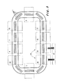
- Figure 1 shows an apparatus comprising an entry station 1.
- the entry station 1 is provided to receive the containers 5, preferably when the latter have already been sterilized, and to load containers 5 into the apparatus.
- containers 5 can be aseptically packaged and then be sterilized at production thereof.
- the entry station 1 comprises receiving means for receiving such packages with sterilized containers 5 and to aseptically unpack the containers.
- the entry station 1 preferably comprises loading means for loading the received containers 5 onto the conveying means 6.
- a part of the entry station 1 (loading means) is located inside the housing while another part of the entry station (the receiving means) is located outside the housing.
- the entry station preferably comprises sterilizing means (not shown) for re-sterilizing at least the upper surface of the elastomer closure of the containers 5 before the latter are loaded onto the conveying means 6.
- the sterilizing means contribute to reinforce the aseptic conditions of the apparatus.
- the sterilizing means preferably comprise means for exposing at least the upper surface of the elastomer closure of the containers 5 to a beam of electrons of a sufficient energy and dose to inactivate micro-organisms present on at least that surface.
- the apparatus further comprises an exit station 4 for removing the containers 5 from the apparatus.
- the containers 5 are removed from the conveying means 6 and transported out of the apparatus.
- the exit station 4 preferably comprises unloading means provided for removing the containers 5 from the conveying means 6.
- the exit station 4 preferably comprises transporting means for transporting the removed containers out of the apparatus.
- the apparatus further comprises a filling station 2.
- the filling station 2 is provided to fill the containers 5 with the product.
- the filling station 2 comprises dosing means and introducing means for filling a predetermined amount of product into the container.
- the introducing means comprise a filling needle and a driving mechanism for driving the filling needle from a withdrawn position into a filling position in which the filling needle has punctured a wall part of the container 5 and back into the withdrawn position.
- the filling station 2 comprises a plurality of dosing means and introducing means in such a manner that multiple containers 5 can be simultaneously filled.
- the apparatus further preferably comprises a sealing station 3.
- the sealing station 3 is provided to seal the containers 5 after the latter has been filled with the product in the filling station 2.
- the sealing station 3 is provided to seal the residual puncture site by melting the material adjacent to the puncture site and then allowing the material to re-solidify thereby sealing the container.
- the sealing station 3 preferably comprises laser means for directing a focused laser beam towards the material adjacent the puncture site.
- the sealing station 3 is provided to seal multiple containers 5 simultaneously.
- the apparatus further comprises conveying means 6 formed by a magnetic conveyor 6 for moving containers 5 along at least the entry station 1, the filling station 2, the sealing station 3 and the exit station 4.
- the conveying means 6 are preferably configured to comprise at least two segments A and B, each segment extending along at least one station.
- FIG 1 an apparatus is shown having conveying means 6 with a first segment A and a second segment B separated by the point-dashed line. The first segment A extends along the filling station 2 while the second segment B extends along the sealing station 3, along the exit station 4 and along the entry station 1.
- carriages are guided on the magnetic conveyor 6 in between guiding walls 30 that extend along the magnetic conveyor 6 and which walls are located on both sides of the conveyor.
- the walls 30, considered in a vertical direction, extend to overlap with the carriages 7 and the containers 5 that are arranged on the magnetic conveyor 6 so that the walls 30 prevent the containers from transversely sliding out of the conveyor 6.
- the guiding walls 30 are formed so that carriages 7 and containers 5 are guided in between the guiding walls 30 along the conveyor 6.
- At least one through hole 32 is provided in the upright walls 30 at the location of the lower end of the walls 30, at the height of the top wall 33 of the magnetic conveyor 6. More preferably, a plurality of through holes is provided. Through these holes 32, water located in between the walls 30 on the magnetic conveyor 6, can escape. In this manner, the cleaning of such apparatus is significantly simplified because cleaning liquid can be spread all over the compartment, which liquid can not become trapped between the guiding walls 30. Also these holes allow a downward flow of sterile air to gently flow out of the cavity, defined by the top wall 33 and the lateral walls 30 of the magnetic conveyor 6, without creating vortex that may increase the risk of contamination by inducing reverse bottom-up airflow.
- the holes 32 are preferably arranged at predetermined intervals along the magnetic conveyor 6.
- the conveying means 6 are arranged in a closed loop so that carriages 7 can be circulated on the conveying means 6 along the stations. This considerably simplifies the entry station 1 and the exit station 4 since only the containers 5, and not the carriages 7, are to be loaded into and out of the apparatus in these stations, and the carriages 7 can be conveyed further in the loop.
- carriages are to be loaded and unloaded from the apparatus in the entry station respectively the exit station, which is complex.
- the containers 5 are preferably placed on carriages 7 at least in sets of at least two containers 5 per carriage 7. These carriages 7 are provided to be handled by the conveying means 6 and are provided to hold the containers 5.
- Figure 2 shows such carriages 7 holding a set of four containers 5.
- carriages 7 can be formed in many ways, for example the carriages 7 can be formed integrally in one piece.
- the carriages 7 comprise two parts releasably connected to each other for example by screwing means. From these two parts, a first carriage part 8 is adapted to be handled by the conveying means 6 while a second carriage part 9 is adapted to hold the set of containers 5. To this end, the first carriage part 8 is constructed complementary with the conveying means 6.
- the second carriage part 9 comprises container holding means for holding the set of containers in position.
- FIG. 4 shows a second carriage part 9 according to a preferred embodiment of the invention.
- the shown second carriage part 9 comprises container holding means for holding a set of two containers 5.
- the holding means in the preferred embodiment as shown in figure 4 are formed by cavities 20 in the second carriage part 9, each cavity 20 being provided to hold one container 5.
- Each cavity 20 extends starting from a side wall 21 of a lateral side portion 22 of the second carriage part 9 and as from that side wall 21 in a direction substantially perpendicular to the moving direction 28 of the carriage into the second carriage part 9 so that containers 5 can slide from a position next to the carriage part to a position into the cavity 20 and onto the second carriage part 9.
- Each cavity 20, starting from the side wall 21, has a length that is determined so that a container 5 can slide into the second carriage part 9 until it reaches an end position, the latter preferably being a substantially optimal container location on the carriage 7 for example where the container is transversely aligned with the filling needle.
- containers 5 for use in the apparatus according to the invention preferably comprise a stand 27 having an outer perimeter which extends, in a direction perpendicular to the mouth-base axis 26 of the container, beyond the outer diameter of the container body. This results in that the container 5 with the stand 27 has an upward-facing surface 19 at the lower part of the container 5.
- the cavity 20 comprises a lip 23 at its upper part so that the upward-facing surface 19 of the stand 27 of the container 5 can slide under the lip 23 in such a manner that the lip prevents the container from being lifted of the carriage 7 when the container 5 is in its end position.
- the holding means comprise a locking member 24 for each cavity 20 for preventing the container 5 from unintentionally sliding out of the end position when the container 5 is located in this end position.
- the locking member 24 can be formed by a leaf spring extending underneath the cavity 20.
- the spring is provided with a protrusion 25 that, when the spring is in rest and the container is in the end position, extends so as to bear upon a side portion of that container 5, which side portion is located towards the side wall 21. In this manner, the container 5 is prohibited to move in the direction of the side wall 21 and thus the container 5 is locked into the end position.
- the leaf spring is to be pressed downward so that the protrusion 25 is moved down so that it does not bear any more upon the side portion of the container 5 and the container 5 can slide over the protrusion 25.
- the magnetic conveyor 6 guiding walls 30 can be provided with additional upright walls 30bis that extend along the magnetic conveyor 6 and which walls are located at at least the lateral side 31 of the conveyor where the containers 5 are positioned on the carriages 7.
- Such guiding walls 30 are shown in figure 8 .
- the wall 30bis considered in a vertical direction, extends to overlap with the containers that are arranged on the magnetic conveyor 6 so that the wall 30bis prevents the containers from sliding out of the cavity 20.
- the guiding walls 30 and additional wall 30bis are formed so that carriages 7 and containers 5 are guided by the walls 30 along the conveyor 6.
- the wall 30bis is interrupted so that containers 5 can slide off the magnetic conveying means 6 while the carriages 7 are still guided in between the walls 30.
- the wall 30bis considering the wall 30bis in a vertical direction, there is no overlap between the containers 5 arranged on the conveyor 6 and the wall 30bis.
- the carriages 7 comprising two parts allow a quick changeover of the apparatus.
- the second carriage parts 9 of the carriages 7 are to be changed. Because the releasable connection between the first carriage part 8 and the second carriage part 9, it is possible to release the second carriage part 9 from the first carriage part, and to connect another second carriage part, suitable for other type of containers, to the first carriage part 8.
- the apparatus comprises a weighing station, preferably two weighing stations 10 and 11. Since the amount of product filled into the container 5 should be highly accurate, weighing systems can be implemented in first instance to provide information to the user of the apparatus and in second instance to provide feedback to the filling station 2.
- a weighing station 11 is provided directly after the filling station 2 so that the filled containers 5 can be weighed.
- the amount of product can then be calculated by subtracting the known average weight of an empty container of the measured weight.
- the apparatus comprises a second weighing station 10 directly before the filling station 2 so that the empty containers 5 can be weighed before filling. In this preferred configuration, the subtraction is not based on a known average weight of an empty container, but on the measured empty weight of the container. This provides much more accuracy to the calculation of amount of product filled into the container 5.
- the weighing stations 10 and 11 are located outside the closed loop. In such configuration, the weighing stations 10 and 11 can not form a bottleneck in the closed loop for the throughput of containers 5 in the apparatus. Since generally, weighing stations with high accuracy require some time to weigh a container, such weighing stations are likely to form a bottleneck. Placing the weighing stations outside the closed loop creates opportunities regarding buffers or parallel weighing to overcome the bottleneck problem.
- the apparatus further comprises a rejecting station 12 for rejecting containers 5 that do not comply with predetermined weighing standards.
- a rejecting station 12 for rejecting containers 5 that do not comply with predetermined weighing standards.
- the amount to be filled setting an upper boundary and a lower boundary to the amount to be filled.
- the rejecting station can be integrated into the closed loop when the weighing stations are in the closed loop.
- the rejecting station can be arranged outside the closed loop.
- the apparatus further comprises a capping station 13 after the sealing station 3.
- the capping station 13 is provided to arrange a cap on the sealed container 5, which cap covers the upper wall of the container.
- Providing a capping station 13 in the apparatus results in that the cap is mounted to the container 5 when the container is in a sterile environment, in particular in the housing enveloping the apparatus. This minimizes the possibility that the upper wall of the container 5 becomes contaminated between the filling of the container 5 and the medic using the container.
- a capping station 13 is provided outside the closed loop.
- the apparatus further comprises a freeze-drying station 14.
- the freeze-drying station 14 is located between the filling station 2 and the sealing station 3, preferably between the rejecting station 12 and the sealing station 3. Since freeze-drying, with respect to filling and sealing, is a slow process, the freeze-drying station is provided with buffering means so that throughput through the slow process can be optimized.
- the buffering means are provided to buffer an entrance 15 and an exit 16 of the freeze-dryer 14. To this end, the entrance buffer 15 of the freeze-drying station 14 is provided to unload the containers 5 from the carriages 7 and to temporary stock a certain amount of containers 5 before they enter the freeze-drier 17.
- the exit buffer 16 is provided to temporary stock the containers 5 coming out of the freeze-drier 17 and to load the stocked containers 5 on the carriages 7.
- the apparatus comprises two closed loops in which a first loop extends along the stations processing the container before the freeze drying step and the second loop extending along the stations processing the containers after the freeze drying step. The two loops being connected by the freeze-drier.
- a process step is performed, which process step takes a certain time.
- the minimum time required for performing a certain process step differs from process step to process step.
- Throughput through a station is optimal if containers are not held longer in that station than the minimum time required for performing the process step of that station.
- the working efficiency of a station can be defined as (the effective workload of a station) / (the maximum capacity of a station).
- the conveying means 6 move the containers 5 along the different stations in the apparatus.
- In an intermitting movement there are different parameters required to define the movement, such as for example the acceleration speed, the maximum moving speed, the moving time and the stopping time.
- the first segment of the conveyor extends along the filling station while the second segment of the conveyor extends along the sealing station. Since carriages in the first segment can be independently moved with respect to carriages in the second segment, it will be possible in this configuration to stop two carriages at a time in the first segment in a position so that containers thereon can be filled, while in the second segment the carriages are stopped one by one in a position where containers thereon can be sealed. In this configuration, the carriages in the first segment of the conveyor move in steps which are twice as long, both in time and in moving distance, with respect to the carriages in the second segment of the conveyor.
- Figure 1 is taken as a starting point for explaining the example, but with following modifications.
- the first segment extending along the filling station
- the second segment extending along the sealing station
- the third segment extending along the entry and exit station.
- the filling station is provided so that six containers can be processed therein.
- the filling station 2 is provided with six filling needles and the sealing station 3 is provided with two laser sealing units.
- the containers 5 are moved into the filling station 2 six at a time so that the six containers 5 can be filled simultaneously. After the four seconds of filling, the filled containers are moved out of the station and six empty containers are moved into the station, this moving of containers in and out of the filling station takes another two seconds. As a result, in the filling station, six containers are filled in four seconds plus two seconds thus in a total of six seconds, thereby having a process speed of one container per second.
- Containers are moved into the sealing station 3 in pairs.
- the pair of containers 5 is simultaneously sealed in one second.
- another pair of containers 5 is to be moved into the sealing station while the sealed pair of containers 5 is to be moved out.
- This moving of containers 5 takes another one second.
- two containers 5 are sealed in one second processing time plus one second moving time thus in a total of two seconds, thereby having a process speed of one container per second, being the same as the process speed of the filling station.
- Containers 5 are moved through the exit 4 and entry station 1 in a continuous manner.
- the speed of movement is three centimetres per second.
- the process speed of the entry 1 and exit station 4 is one container per second being the same as the process speed of the filling 2 and the sealing station 3.
- the containers 5 can be moved in a different manner through different stations while a same amount of containers 5 is processed by each of the stations over a larger period of time.
- the conveying means 6 in the present invention are formed by magnetic conveying means.
- a magnetic conveyor is known to have a high flexibility.
- first carriage parts 8 of the carriages comprise so-called pucks 18, which are the moving elements being permanent magnets that are driven by the magnetic rail in the magnetic conveyor. Since a plurality of pucks 18 can be driven independently from one another and with high precision, the magnetic conveyor provides further advantages to the present invention in that the carriages 7 can be independently moved.
- the carriages 7 being independently moveable, results in that an infinite number of segments can be defined along the magnetic rail. In practice however, the maximum number of segments will substantially correspond to the amount of stations along the rail.
- the magnetic conveyor provides the further advantage in that there are less moving mechanical parts, and therefore cleaning and decontamination operations can be performed in a much easier and effective way, compared to conventional conveyors.
- the magnetic conveyor 6 in the present invention is of the type having a Linear Synchronous Motor (LSM).
- LSMs generate propulsive force by running current through a stator, which creates an electro-magnetic field. This electro-magnetic field interacts with a permanent magnet, the puck, located on the carriage 7 to create thrust.
- the permanent magnet serves as the motor secondary, equivalent to a rotor in conventional motors enabling linear motion.
- the carriage 7 is propelled by the moving electro-magnetic field, traveling along as electric current is applied to the stator beneath the vehicle.
- Such magnetic conveyors 6 using LSM technology do not comprise moving elements in the housing, only a stator.
- each carriage 7 can be independently moved along the conveyor 6.
- Such magnetic conveyor 6 using LSM technology is illustrated in figure 6 on the right hand side.
- the magnetic conveyor 6 can be of the type where magnets are located in the housing on a mechanical conveyor. There magnets drive the magnets that are positioned on the carriages to thereby drive the carriages.
- Such magnetic conveyor 6 is illustrated in figure 7 .
- the present invention substantially relates to the conveying of containers along different stations wherein these containers are to be aseptically filled with a product
- an apparatus comprising only three stations, being an entry station, an exit station and a filling station, can be formed using the teaching of the present invention.
- An optimal throughput can be determined for conveying containers along the three stations and the conveying means can be segmented to convey the containers along one of the three stations independently from containers along the other of the three stations.
- the apparatus comprises all features of claim 1 but without the sealing station for sealing the container.
- Acceleration forces applied to the containers can be considerably high when using conveying means according to the present invention, in particular when using a magnetic conveyor and more in particular in the curves of the closed loop. This is a result of the conveying means independently moving containers in different segments thereof. Between different segments, container speed is changed from one to another speed, resulting in acceleration forces. When product has been filled into the container in the filling station, the acceleration forces tend to shake the product filled into the container. When the container is of the type having an opening at the top part of the container, product filled in the container can be shaken out of this container thereby spilling product, which is to be avoided. Therefore the containers used in the present invention are preferably pre-closed and provided to be filled using a filling needle.
- the filling needle punctures the pre-closed container and fills the container using the needle.
- the pre-closed container shows an opening that is at least not larger than the diameter of the needle. This rather small opening is negligible when considering spill of the container due to the acceleration forces.
- the container is pre-closed with an elastomer closure, that, due to its elasticity, re-closes the container upon withdrawal of the needle thereby not leaving an opening at all.
- a sealing station is preferably but not mandatory for aseptically filling a container.
- Figure 5 illustrates an apparatus from another point of view which is relevant in the invention, namely in cross section.
- the apparatus is divided in an upper compartment 34 and a lower compartment 35 separated by a liquid impermeable wall 36.
- the upper compartment 34 is provided to enclose an aseptic environment.
- the upper compartment 34 preferably comprises sterile air flow means 37 located at the upper sealing of the upper compartment 34, which air flow means 37 are provided to create a laminar downward stream of sterile air in the upper compartment 34.
- the upper compartment comprises at least one opening 38 in its side walls at the height of the liquid impermeable wall 36.
- the opening 38 can be configured to connect the upper compartment with the environment. However the opening 38 can be enveloped by air collecting means provided to collect the laminar downward stream of sterile air, thereby fully separating the upper compartment from the environment.
- the containers to be filled are handled in the upper compartment 34 preferably in a zone thereof where the downward laminar stream of air is not disturbed.
- the conveying means 6, and consequently also the stations are arranged in the upper compartment 34 so that the containers 5 are moved at a second height H from the liquid impermeable wall 34, which second height H is preferably larger than said distance D.
- the height H is preferably larger than 5 cm, more preferably larger than 10 cm, most preferably larger than 15 cm.
- the height H is preferably smaller than 50 cm, more preferably smaller than 40 cm, most preferably smaller than 35 cm.
- the upper compartment 34 is provided to be cleaned and decontaminated with cleaning and decontaminating liquids suitable for cleaning and decontaminating industrial aseptic machines.
- the floor wall of the upper compartment is formed by a liquid impermeable wall 36.
- the elements that form part of, and are located in the upper compartment 34 are preferably liquid proof.
- the upper compartment 34 comprises only part of the stations, particularly the part that handles and manipulates the containers. Another part of the station drives and controls the handling and manipulating of containers, which part is at least partly comprised by the lower compartment 35.
- handling and manipulating means 39 can be more easily designed to be waterproof than driving and controlling means 40, which latter often involve electrical signals and power.
- driving and controlling means 40 is located outside the sterile upper compartment 34, in the lower compartment 35, there is no need to keep the driving and controlling means 40 sterile, which is a significant advantage.
- connection 41 shown in figure 5 on the left hand side is a static connection.
- a connector 44 being a non-moveable element 44, extends from the handling and manipulating means 34 to the driving and controlling means 40, through the liquid impermeable wall 36 and is fixed and solidly sealed to this wall 36 so that liquid is prevented from passing through between the connector 44 and the wall 36.
- the connector 44 provides in a connection which is assured liquid tight between the connector 44 and the wall 36.
- the connector 44 can comprise a hollow interior through which electric cables extend.
- the connector 44 can also be formed as, or can comprise therin a product conduit through which a product such as a cleaning liquid or a filling product, particularly medicament, to be filled in the container 5, can be transported.
- the central connection 42 shown in figure 5 is a dynamic connection.
- a moveable element 45 is fixed to the liquid impermeable wall 36 through the intermediary of a flexible element 46.
- the flexible element 46 itself is liquid impermeable.
- the flexible element 46 is fixed and solidly sealed to the moveable element 45 with one extremity and is fixed and solidly sealed to the liquid impermeable wall 36 with another extremity. Between the one extremity and the other extremity, the flexible element 46 is liquid impermeable so that by securing these extremities respectively to the moveable element 45 and the wall 36, liquid is prevented from passing through between the moveable element 45 and the wall 36.
- the dynamic connection 42 is thereby provided to transmit a movement, illustrated by arrow 47, from the lower 35 to the upper 34 compartment.
- the movement is however limited by the stroke of elasticity and/or flexibility of the flexible element 46.
- the movement can be an upward-downward movement whereby the moveable element 45 translates over a predetermined distance.
- the movement can also be a rotational movement however with a limited angle of rotation preferably within a range from 0° to 360°. Further movements can be obtained, however the movements are of a pendulous type, being the type of going from a first extreme position towards a second extreme position and back to the first. The movement will not reach further than the predetermined extreme positions.
- the operational connection which is shown in figure 5 on the right hand side is a wireless connection 43.
- the wireless connection 43 can comprise transfer of data, via known wireless data transfer means, for example to transmit data from sensors from the upper compartment 34 to the lower compartment 35.
- the wireless connection 43 can furthermore comprise magnetic connection between an element in the upper 34 compartment and a further element in the lower compartment 35 such as for example in the magnetic conveyor.
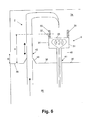
- Figure 6 shows a cross section at the location of the filling station 2 of the apparatus according to the invention.
- the shown magnetic conveyor 6 is of the type having a Linear Synchronous Motor, which motor is fed via electric cables that extend through the liquid impermeable wall via a static connection 41.
- the filling element is shown which is mounted through the liquid impermeable wall 36 so that it can move upward and downward from a retracted position where containers can be moved underneath the filling member to a container puncturing position where the container is punctured with the filling member.
- the filling element is to this end connected to driving means located in the lower compartment 35 via a dynamic connection 42.
- the intermediary flexible element 46 forms a connection between the moveable filling element and the liquid impermeable wall 36 so that the zone between the filling element and the wall 36 is sealed and free of any leaks.
- the filling element is furthermore hollow and provided so that filling product can be transported through it.
- the magnetic conveyor 6 is arranged in the apparatus on poles 48 supporting the conveyor 6 at a height so that containers 5 can be moved at a predetermined height H from the liquid impermeable wall 36.
- the predetermined height H is larger than the distance D between the side walls of the upper compartment 34 and the liquid impermeable wall 36. In this manner, the containers 5 are transported and manipulated, particularly filled and sealed, in a zone of the upper compartment 34 where a downward laminar stream of sterile air flows.
- FIG. 7 shows a configuration where the housing of the magnetic conveyor 6 is comprised by the lower compartment 35, and consequently where the liquid impermeable wall 36 curls over at least a part of the magnetic conveyor 6.
- the driving means of the magnetic conveyor 6 can be formed by continuously rotating, or by continuous linearly moving elements 49, which elements 49 drive the magnets inside the housing. Such continuously moving elements 49 can not be transmitted in a guaranteed leak free manner through the liquid impermeable wall 36, as explained above.
- the continuously moving elements 49 are not transmitted through the liquid impermeable wall, namely the liquid impermeable wall curls over the housing of the magnetic conveyor.
- this configuration provides in an alternative to the use of a magnetic conveyor 6 of the type having a Linear Synchronous Motor.
- the rotating elements 49 are completely comprised by the lower compartment 35, and consequently do not extend through the liquid impermeable wall 36.
- the liquid impermeable wall 36 can be defined as that wall part which separates the lower compartment 35 from the upper compartment 34 in a liquid tight manner.
Landscapes
- Engineering & Computer Science (AREA)
- Mechanical Engineering (AREA)
- General Engineering & Computer Science (AREA)
- Microelectronics & Electronic Packaging (AREA)
- Filling Of Jars Or Cans And Processes For Cleaning And Sealing Jars (AREA)
Abstract
An apparatus for filling a product, in particular a medicament, under aseptic conditions into a container 5, said apparatus comprising:
• an entry station 1 for entering said container 5 into said apparatus;
• a filling station 2 for introducing said product into said container 5;
• a sealing station 3 for sealing said container 5;
• an exit station 4 for removing said container 5 from said apparatus; and
• conveying means 6 for moving said container 5 along at least the above-mentioned stations, said conveying means 6 comprising a first segment A extending along at least one of said above-mentioned stations, and a second segment B extending along at least another of said above-mentioned stations,
said apparatus comprises a carriage 7 provided to hold a set of at least two containers 5, and said conveying means 6 being provided to handle said carriage 7, wherein said conveying means 6 is provided to independently move a first carriage in said first segment A with respect to a second carriage in said second segment B.
Description
- The present invention relates to an apparatus for filling a product, in particular a medicament, under aseptic conditions into a container, said apparatus comprising an upper compartment separated from a lower compartment by a liquid impermeable wall, wherein said apparatus further comprises:
- an entry station for entering said container into said upper compartment;
- a filling station for introducing said product into said container;
- a sealing station for sealing said container;
- an exit station for removing said container from said apparatus; and
- conveying means for moving said container along at least the above-mentioned stations within said upper compartment,
- The filling of a medicament into a container is in practice typically executed in an aseptic environment. Aseptic environments are organized in classes, in which each further class refers to a higher sterility of the environment. An aseptic environment established in an apparatus prevents the medicament and container being handled in the apparatus from being contaminated, thus it prevents the penetration of contaminants from the environment into the inside of the apparatus. To this end, such apparatus for filling a medicament comprises an aseptic compartment, referred to as the upper compartment, where the containers are handled and manipulated, and which compartment is provided to comply with the standards laid down in the class of sterility that corresponds to the predetermined requirements for filling the medicament.
- The sterile compartment is furthermore formed so that it is cleanable with a cleaning liquid. In order to prevent this liquid from reaching the machinery of the stations, being the driving and controlling means provided for driving and controlling the manipulating and handling means, the machinery is located in another compartment which is separated form the sterile compartment by a liquid impermeable wall. The machinery, comprising for example an electromotor and a plurality of electrically driven actuators, is typically less waterproof than the handling and manipulating means. Housing the driving and controlling means in compartments separate from the handling and manipulating means results in that the driving and controlling means can substantially be held dry while the sterile compartment is flushed with liquid for cleaning purposes. Furthermore in such configuration, there is no need to keep the machinery sterile, however there is a need to prevent the machinery from being contaminated by hazardous products which may be filled into containers in the upper compartment.
- In such apparatus, one or a plurality of operational connections are established through the liquid impermeable wall between on the one hand the driving and controlling means in the lower compartment and on the other hand the handling and manipulating means in the upper compartment. These operational connections transmit movements, electrical signals and currents, products from the lower compartment to the upper compartment and vice versa.
- A drawback of such apparatus is that the operational connections, particularly the operational connections which transmit movements from the lower to the upper compartment, are not formed to guarantee that contaminants can not move from the upper to the lower compartment and vice versa. Therefore, the sterility of the upper compartment can not be fully guaranteed. When filling a container with a hazardous product, being a product that can harm for example a human being, not only contamination from the lower compartment to the upper compartment is to be prevented for sterility purposes, but also the contamination of the lower compartment with hazardous products should be prevented. If such contamination can not be prevented, the safety of a human being working on the machinery can not be guaranteed, since hazardous products may have reached the lower compartment via the operational connections.
- It is an object of the present invention to provide an apparatus for filling a product under aseptic conditions into a container, having two compartments which are separated in such a manner that contaminants and/or harmful products are prevented from moving from one to another of the two compartments.
- To this end, the apparatus according to the present invention is characterised in that said conveying means is formed by a magnetic conveyor, and said at least one operational connection consists of one or a plurality of the following:
- a static connection for establishing an electrical connection or product-pipeline, and being formed by a connector which is solidly sealed in an opening through said liquid impermeable wall in such a manner as to prevent liquid from moving between said opening and said connector;
- a dynamic connection formed by a moveable element which extends through said liquid impermeable wall and is moveably fixed to said wall through the intermediary of a flexible sealing element, which sealing element is solidly fixed to said moveable element and solidly fixed to said wall in such a manner as to form a leak tight sealing between said moveable element and said wall; and
- a wireless connection formed by compatible first and second wireless connectors are respectively provided in the upper and lower compartment
- The very specific selection of operational connections in combination with the conveying means being formed by a magnetic conveyor, provides in a solution whereby the separation between lower compartment and upper compartment can be fully guaranteed. Thereby, the static, dynamic and/or wireless connections are each configured to form a barrier for contaminants. The static connection is solidly sealed to the liquid impermeable wall, the dynamic connection is solidly sealed to the liquid impermeable wall through the intermediary of a flexible element, and for the wireless connection, no opening is formed so that no sealing is required.
- The particular combination of the specific connection means and the magnetic conveyor provides in a significant synergetic effect, which proves to be very valuable in aseptic filling machines. In the prior art apparatuses, particularly the dynamic connections are sealed by providing a sliding seal between the wall and the moveable element, for example an O-ring, which is a type of seal utilised in rotating equipment, such as pumps and compressors. Typically, when a pump operates, the liquid could leak out of the pump between the rotating shaft and the stationary pump casing. Since the shaft rotates, preventing this leakage can be difficult. In such configurations, O-rings or equivalent means are used to prevent leakage. Applying such O-rings in the apparatus for sealing the dynamic connections will indeed prevent the majority of the liquid to flow from the upper into the lower compartment. However because the O-ring slides against the moveable element, it can not be guaranteed that hazardous products do not emigrate from the upper compartment to the lower compartment via the elements sliding with respect to each other. Furthermore when cleaning such apparatus, it can not be guaranteed that cleaning liquid follows the same path in between the elements sliding with respect to each other as the hazardous product follows, thereby it can not be guaranteed that all hazardous products are removed. Thus when O-rings are used, the solution to be sure that all hazardous products are removed from the apparatus, is to completely dismantle and clean every part in the lower compartments additionally to thoroughly cleaning the upper compartment.
- The present invention explicitly claiming an element whether or not via an intermediary piece sealed to the liquid impermeable wall, thereby eliminates these problems, since it can be assured that through the solidly sealed connections, no hazardous products can leak. The magnetic conveyor thereby provides in a manner to continuously move the containers without a continuously moving mechanical connection between the lower and the upper compartment. Thereby, the magnetic conveyor in combination with the static, dynamic and/or wireless connections provides in a synergetic effect that enables the machine to be manufactured guaranteeing the isolation of the lower with respect to the upper compartment and vice versa.
- The particular choice of a magnetic conveyor as forming the conveying means, further results in that the transmission of power from the driving means to the containers is wireless, namely via a magnetic field. Thereby, the number of moving elements which are exposed to contaminants can be reduced to a minimum. The driving means can be fully mechanically separated from the elements that are driven, which are the containers and in a particular embodiment of the apparatus also the carriages, and therefore these driving means can be enclosed by an enclosure which prevents the driving means from being contaminated by the medicament. This results in that a magnetic conveyor, unlike a conventional mechanical conveyor, does not require a rotating axis to extend through the liquid impermeable wall.
- Furthermore, a magnetic conveyor provides more conveying flexibility than a conventional conveying system. Using existing magnetic conveying systems, a set of containers can be conveyed independently from another set of containers. A further advantage of using a magnetic conveyor as described in this invention is that there is a considerably less mechanical frictional contact between the conveyor and the containers with respect to between a conventional conveyor and the containers. Furthermore, less mechanical parts are necessary to build such magnetic conveyor with respect to a conventional conveyor. Furthermore, the less mechanical parts result in an improved cleanability and associated sanitization with respect to conventional conveyors. This is an advantage especially in the aseptic handling of containers. As a further result, there is less need to clean the apparatus, thus increasing the up-time of the apparatus.
- Preferably, said upper compartment comprises sterile air flow means provided to create a downward laminar air flow of sterile air in said upper compartment. Such sterile air flow means thereby create a sterile environment wherein the containers can be filled. The sterile air flow means, in combination with the design of the upper compartment of the apparatus, provide in a sterile environment with a predetermined class of sterility.
- Preferably, said magnetic conveyor comprises a housing that has at least a liquid impermeable top wall and liquid impermeable side walls, said magnetic conveyor further comprising magnet-driving means being enclosed by said housing and being provided to drive a magnet that is located outside said housing. While cleaning the upper compartment of the apparatus, a downward stream of cleaning liquid is introduced in the apparatus. By providing the magnetic conveyor with a housing having liquid impermeable top and side walls, the cleaning liquid can not leak into the housing of the conveyor. Thereby, the magnet-driving means which are provided in the housing are protected against the cleaning liquid.
- Preferably, said magnetic conveyor comprises upright guiding walls at the location of the lateral sides of said conveyor and extending along the conveyor so that said container is guidable on said housing and between said guiding walls. The guiding walls provide a rail wherein the containers can be moved. Thereby, the moving path that is followed by the containers is defined. Preferably, said guiding walls comprise at the location of their lower ends through holes. These holes allow liquid to escape from between said guiding walls, in particular, these holes allow cleaning liquid to escape so that no manual intervention is required after cleaning for emptying the rail. Furthermore, these holes allow a downward flow of sterile air, flowing in the upper compartment, to flow through the rail, thereby preventing the creation of vortex in and above the rail. Such vortex increases the risk of contamination by reverse airflow.
- Preferably, said conveying means form a closed loop, and said stations are arranged within said loop. The closed loop results in that carriages can circulate in the machine and should not be loaded and removed from the conveying means at respectively the entry and the exit station.
- Preferably, said magnetic conveyor is provided to move said container through the intermediary of a carriage which carriage comprises a first carriage part and a second carriage part, said first carriage part being operatively connectable to said magnetic conveyor to be moved by the latter and said second carriage part is releaseably connected to said first carriage part and said second carriage part is constructed to hold a set of at least two containers.
- The use of carriages in the conveying of the containers is advantageous in reducing product changeover down time. Conventionally, the containers are individually handled by a conventional mechanical conveyor. This results in that for enabling the apparatus to handle containers with different outer dimensions, the complete conveyor must be changed so as to be suitable for handling these containers with different outer dimensions. Using carriages on a conveyor, only the carriages are to be changed in such situation. Changing carriages for being able to convey containers of a different dimension, can be carried out in a smaller period of time than changing the complete conveyor, and therefore the carriages contribute in reducing the down time and costs in product changeovers. Furthermore, the carriages can be sterilized outside the apparatus before entering in the apparatus, thus substantially reducing the costs for sterilizing the apparatus after a product changeover. Carriages having a first part and a second part further contribute to the reducing of downtime due to process changeover. Namely, in switching from handling one type to another type of container, only the second carriage parts of the carriages are to be changed. These second carriage parts can be designed and prepared in advance so as to shorten the downtime. Furthermore, the first carriage part, that is constructed in such a manner that it can be moved by the conveying means, can for this reason be quite expensive, and must not be changed in the process changeover.
- Preferably, said carriage is provided to hold said set of at least two containers in a row that extends parallel to a moving direction of said conveying means. In conventional conveying systems, containers are often moved in a continuous or in an intermitting manner. In continuous conveying, all containers are moved at a same substantially constant speed, for which the containers preferably are arranged in a long continuous row. Certain processing stages are preferably fed by such long continuous row to work optimally. In intermitting conveying, the containers are moved stepwise. Certain processing stages, for example the filling stage, are preferably fed in an intermitting way to be able to operate optimally. Providing the containers on the carriages in a row that extends parallel to a moving direction of the conveyor is advantageous because the row of containers creates a buffer in changing from a continuous to an intermitting conveying of containers. Preferably, the row comprises at least four containers, more preferably at least six containers.
- Preferably, said apparatus further comprises a first container weighing station and a second container weighing station wherein said first container weighing station is located before the filling station and said second container weighing station is located after the filling station. Furthermore, said apparatus preferably comprises a rejecting station which is located after said second container weighing station and which is provided to reject containers that do not correspond to predetermined weighing standards. Furthermore, said apparatus preferably comprises a container capping station which is located after said sealing station. Furthermore, said apparatus preferably comprises a freeze drying station located between said filling station and said sealing station and which is provided for lyophilizing said product in said container. Preferably, the above-mentioned stations are arranged along said conveying means, preferably in said loop. Each station provides more functionality to the apparatus in adding an additional working step which can be performed on a container.
- The invention will now be described in more details with respect to the drawings illustrating some preferred embodiments of the invention. In the drawings:
-
figure 1 illustrates an apparatus according to the invention; -
figure 2 illustrates a carriage carrying a set of containers; -
figure 3 illustrates an apparatus according to a preferred embodiment of the invention; -
figure 4 illustrates a preferred embodiment of a second carriage part; -
figure 5 illustrates an apparatus in cross section showing three operational connections between a lower and an upper compartment; -
figure 6 illustrates an apparatus in cross section showing a filling station and a magnetic conveyor; -
figure 7 illustrates an apparatus in cross section showing a further magnetic conveyor; and -
figure 8 illustrates a cross section of a magnetic conveyor applied in the present invention. - In the drawings a same reference number has been allocated to a same or analogous element.
- The apparatus according to the present invention is provided to fill
containers 5 with product, in particular with medicaments. In this text, the term product is preferably to be interpreted as medicaments. However it will be clear that other products than medicaments can require aseptic filling into containers, such as cosmetic liquids or powders. Because of the aseptic requirements for handling such products, in particular medicaments, the apparatus has to comply with very strict requirements in order to ensure safe and aseptic operation. Therefore, the apparatus preferably operates under laminar air flow with High Efficiency Particulate Air (HEPA) filtration, as defined by the DOE standard adopted by most American industries and/or as defined by the European Norm EN 1822-1. Furthermore, the apparatus preferably is located in a sterile environment, more preferably the apparatus comprises a housing enveloping substantially all elements of the apparatus in such a manner that contamination is prevented from entering the apparatus from the outside. -
Containers 5 to be filled by the apparatus are preferably vials as described inPCT/EP03/09151 , which vials are briefly described hereafter. This vial has a mouth opening and a neck immediately downward of the mouth opening. The vial furthermore has a rim in the form of a flange having upper and lower surfaces extending transverse to the upper-lower axis. The vial, as provided for the process of the present invention, is preferably provided with a closure system comprising an elastomer closure, a clamp part and a closure part as further defined below. The elastomer closure part is shaped to sealingly engage with the mouth opening, having a lower surface facing the interior of the vial and an opposite upper surface facing away from the vial, and capable of being punctured by a needle. The clamp part is able to engage with the vial, particularly with the rim of the mouth opening, and able to bear upon the upper surface of the closure part to hold the closure part in a closing relationship with the mouth opening. The clamp part has an aperture therein through which a region of the upper surface of the closure part is exposed when the clamp part is engaged with the vial. The vial furthermore preferably comprises a stand having an outer perimeter which extends, in a direction perpendicular to the mouth-base axis direction of the vial, beyond the outer diameter of the vial body, and has an upward- facing surface. -
Figure 1 shows an apparatus comprising anentry station 1. Theentry station 1 is provided to receive thecontainers 5, preferably when the latter have already been sterilized, and to loadcontainers 5 into the apparatus. In this regard,containers 5 can be aseptically packaged and then be sterilized at production thereof. Preferably theentry station 1 comprises receiving means for receiving such packages with sterilizedcontainers 5 and to aseptically unpack the containers. Theentry station 1 preferably comprises loading means for loading the receivedcontainers 5 onto the conveyingmeans 6. In such configuration, a part of the entry station 1 (loading means) is located inside the housing while another part of the entry station (the receiving means) is located outside the housing. Between the receiving means and the loading means, the entry station preferably comprises sterilizing means (not shown) for re-sterilizing at least the upper surface of the elastomer closure of thecontainers 5 before the latter are loaded onto the conveyingmeans 6. The sterilizing means contribute to reinforce the aseptic conditions of the apparatus. The sterilizing means preferably comprise means for exposing at least the upper surface of the elastomer closure of thecontainers 5 to a beam of electrons of a sufficient energy and dose to inactivate micro-organisms present on at least that surface. - The apparatus further comprises an
exit station 4 for removing thecontainers 5 from the apparatus. In theexit station 4, thecontainers 5 are removed from the conveyingmeans 6 and transported out of the apparatus. To this end, theexit station 4 preferably comprises unloading means provided for removing thecontainers 5 from the conveyingmeans 6. Furthermore, theexit station 4 preferably comprises transporting means for transporting the removed containers out of the apparatus. - The apparatus further comprises a filling
station 2. The fillingstation 2 is provided to fill thecontainers 5 with the product. To this end, the fillingstation 2 comprises dosing means and introducing means for filling a predetermined amount of product into the container. The introducing means comprise a filling needle and a driving mechanism for driving the filling needle from a withdrawn position into a filling position in which the filling needle has punctured a wall part of thecontainer 5 and back into the withdrawn position. Preferably, the fillingstation 2 comprises a plurality of dosing means and introducing means in such a manner thatmultiple containers 5 can be simultaneously filled. - The apparatus further preferably comprises a sealing station 3. The sealing station 3 is provided to seal the
containers 5 after the latter has been filled with the product in the fillingstation 2. Preferably, the sealing station 3 is provided to seal the residual puncture site by melting the material adjacent to the puncture site and then allowing the material to re-solidify thereby sealing the container. To this end, the sealing station 3 preferably comprises laser means for directing a focused laser beam towards the material adjacent the puncture site. Preferably, the sealing station 3 is provided to sealmultiple containers 5 simultaneously. - The apparatus further comprises conveying
means 6 formed by amagnetic conveyor 6 for movingcontainers 5 along at least theentry station 1, the fillingstation 2, the sealing station 3 and theexit station 4. The conveying means 6 are preferably configured to comprise at least two segments A and B, each segment extending along at least one station. Infigure 1 , an apparatus is shown having conveyingmeans 6 with a first segment A and a second segment B separated by the point-dashed line. The first segment A extends along the fillingstation 2 while the second segment B extends along the sealing station 3, along theexit station 4 and along theentry station 1. - In
figure 6 , carriages are guided on themagnetic conveyor 6 in between guidingwalls 30 that extend along themagnetic conveyor 6 and which walls are located on both sides of the conveyor. Thewalls 30, considered in a vertical direction, extend to overlap with thecarriages 7 and thecontainers 5 that are arranged on themagnetic conveyor 6 so that thewalls 30 prevent the containers from transversely sliding out of theconveyor 6. Thereby, the guidingwalls 30 are formed so thatcarriages 7 andcontainers 5 are guided in between the guidingwalls 30 along theconveyor 6. - Preferably, at least one through
hole 32 is provided in theupright walls 30 at the location of the lower end of thewalls 30, at the height of thetop wall 33 of themagnetic conveyor 6. More preferably, a plurality of through holes is provided. Through theseholes 32, water located in between thewalls 30 on themagnetic conveyor 6, can escape. In this manner, the cleaning of such apparatus is significantly simplified because cleaning liquid can be spread all over the compartment, which liquid can not become trapped between the guidingwalls 30. Also these holes allow a downward flow of sterile air to gently flow out of the cavity, defined by thetop wall 33 and thelateral walls 30 of themagnetic conveyor 6, without creating vortex that may increase the risk of contamination by inducing reverse bottom-up airflow. Theholes 32 are preferably arranged at predetermined intervals along themagnetic conveyor 6. - Preferably, the conveying
means 6 are arranged in a closed loop so thatcarriages 7 can be circulated on the conveyingmeans 6 along the stations. This considerably simplifies theentry station 1 and theexit station 4 since only thecontainers 5, and not thecarriages 7, are to be loaded into and out of the apparatus in these stations, and thecarriages 7 can be conveyed further in the loop. In an embodiment, not having a conveyingmeans 6 that is arranged in a closed loop, but where the conveyingmeans 6 extend in a line having a first end and a second end, carriages are to be loaded and unloaded from the apparatus in the entry station respectively the exit station, which is complex. - In the apparatus, the
containers 5 are preferably placed oncarriages 7 at least in sets of at least twocontainers 5 percarriage 7. Thesecarriages 7 are provided to be handled by the conveyingmeans 6 and are provided to hold thecontainers 5.Figure 2 showssuch carriages 7 holding a set of fourcontainers 5. According to the invention,carriages 7 can be formed in many ways, for example thecarriages 7 can be formed integrally in one piece. - Preferably, the
carriages 7 comprise two parts releasably connected to each other for example by screwing means. From these two parts, afirst carriage part 8 is adapted to be handled by the conveyingmeans 6 while asecond carriage part 9 is adapted to hold the set ofcontainers 5. To this end, thefirst carriage part 8 is constructed complementary with the conveyingmeans 6. Thesecond carriage part 9 comprises container holding means for holding the set of containers in position. -
Figure 4 shows asecond carriage part 9 according to a preferred embodiment of the invention. The shownsecond carriage part 9 comprises container holding means for holding a set of twocontainers 5. The holding means in the preferred embodiment as shown infigure 4 , are formed bycavities 20 in thesecond carriage part 9, eachcavity 20 being provided to hold onecontainer 5. Eachcavity 20 extends starting from aside wall 21 of alateral side portion 22 of thesecond carriage part 9 and as from thatside wall 21 in a direction substantially perpendicular to the movingdirection 28 of the carriage into thesecond carriage part 9 so thatcontainers 5 can slide from a position next to the carriage part to a position into thecavity 20 and onto thesecond carriage part 9. Eachcavity 20, starting from theside wall 21, has a length that is determined so that acontainer 5 can slide into thesecond carriage part 9 until it reaches an end position, the latter preferably being a substantially optimal container location on thecarriage 7 for example where the container is transversely aligned with the filling needle. - As mentioned above,
containers 5 for use in the apparatus according to the invention preferably comprise astand 27 having an outer perimeter which extends, in a direction perpendicular to the mouth-base axis 26 of the container, beyond the outer diameter of the container body. This results in that thecontainer 5 with thestand 27 has an upward-facingsurface 19 at the lower part of thecontainer 5. - Preferably the
cavity 20 comprises alip 23 at its upper part so that the upward-facingsurface 19 of thestand 27 of thecontainer 5 can slide under thelip 23 in such a manner that the lip prevents the container from being lifted of thecarriage 7 when thecontainer 5 is in its end position. - Preferably, the holding means comprise a locking
member 24 for eachcavity 20 for preventing thecontainer 5 from unintentionally sliding out of the end position when thecontainer 5 is located in this end position. The lockingmember 24 can be formed by a leaf spring extending underneath thecavity 20. The spring is provided with aprotrusion 25 that, when the spring is in rest and the container is in the end position, extends so as to bear upon a side portion of thatcontainer 5, which side portion is located towards theside wall 21. In this manner, thecontainer 5 is prohibited to move in the direction of theside wall 21 and thus thecontainer 5 is locked into the end position. To unlock thecontainer 5, the leaf spring is to be pressed downward so that theprotrusion 25 is moved down so that it does not bear any more upon the side portion of thecontainer 5 and thecontainer 5 can slide over theprotrusion 25. - As an alternative to the locking
member 24, themagnetic conveyor 6guiding walls 30 can be provided with additional upright walls 30bis that extend along themagnetic conveyor 6 and which walls are located at at least thelateral side 31 of the conveyor where thecontainers 5 are positioned on thecarriages 7. Such guidingwalls 30 are shown infigure 8 . The wall 30bis, considered in a vertical direction, extends to overlap with the containers that are arranged on themagnetic conveyor 6 so that the wall 30bis prevents the containers from sliding out of thecavity 20. Thereby, the guidingwalls 30 and additional wall 30bis are formed so thatcarriages 7 andcontainers 5 are guided by thewalls 30 along theconveyor 6. At the location of theentry 1 andexit 4 station, the wall 30bis is interrupted so thatcontainers 5 can slide off the magnetic conveyingmeans 6 while thecarriages 7 are still guided in between thewalls 30. To this end, at theentry 1 andexit 4 station, considering the wall 30bis in a vertical direction, there is no overlap between thecontainers 5 arranged on theconveyor 6 and the wall 30bis. - The
carriages 7 comprising two parts allow a quick changeover of the apparatus. To change the apparatus from handling one type of vial to handling another type of vial, thesecond carriage parts 9 of thecarriages 7 are to be changed. Because the releasable connection between thefirst carriage part 8 and thesecond carriage part 9, it is possible to release thesecond carriage part 9 from the first carriage part, and to connect another second carriage part, suitable for other type of containers, to thefirst carriage part 8. - In a preferred embodiment of the apparatus according to the invention, the apparatus comprises a weighing station, preferably two weighing
stations 10 and 11. Since the amount of product filled into thecontainer 5 should be highly accurate, weighing systems can be implemented in first instance to provide information to the user of the apparatus and in second instance to provide feedback to the fillingstation 2. A weighing station 11 is provided directly after the fillingstation 2 so that the filledcontainers 5 can be weighed. The amount of product can then be calculated by subtracting the known average weight of an empty container of the measured weight. Preferably, the apparatus comprises a second weighingstation 10 directly before the fillingstation 2 so that theempty containers 5 can be weighed before filling. In this preferred configuration, the subtraction is not based on a known average weight of an empty container, but on the measured empty weight of the container. This provides much more accuracy to the calculation of amount of product filled into thecontainer 5. - In an alternative preferred embodiment, the weighing
stations 10 and 11 are located outside the closed loop. In such configuration, the weighingstations 10 and 11 can not form a bottleneck in the closed loop for the throughput ofcontainers 5 in the apparatus. Since generally, weighing stations with high accuracy require some time to weigh a container, such weighing stations are likely to form a bottleneck. Placing the weighing stations outside the closed loop creates opportunities regarding buffers or parallel weighing to overcome the bottleneck problem. - In the preferred embodiment, the apparatus further comprises a rejecting
station 12 for rejectingcontainers 5 that do not comply with predetermined weighing standards. In the filling of the containers, there is a predetermined amount of product that is to be filled in thecontainers 5. Furthermore, there is a predetermined tolerance on the amount to be filled setting an upper boundary and a lower boundary to the amount to be filled. Using the weighing station 11 or weighingstations 10 and 11, the amount of product that has been filled into aparticular container 5 can be accurately determined. When the determined amount is not within the predetermined boundaries, the container does not comply with the predetermined weighing standards and can be rejected by the rejectingstation 12. The rejecting station can be integrated into the closed loop when the weighing stations are in the closed loop. As an alternative, the rejecting station can be arranged outside the closed loop. - In the preferred embodiment, the apparatus further comprises a
capping station 13 after the sealing station 3. Thecapping station 13 is provided to arrange a cap on the sealedcontainer 5, which cap covers the upper wall of the container. Providing acapping station 13 in the apparatus results in that the cap is mounted to thecontainer 5 when the container is in a sterile environment, in particular in the housing enveloping the apparatus. This minimizes the possibility that the upper wall of thecontainer 5 becomes contaminated between the filling of thecontainer 5 and the medic using the container. In an alternative embodiment, acapping station 13 is provided outside the closed loop. - Preferably, the apparatus further comprises a freeze-drying
station 14. The freeze-dryingstation 14 is located between the fillingstation 2 and the sealing station 3, preferably between the rejectingstation 12 and the sealing station 3. Since freeze-drying, with respect to filling and sealing, is a slow process, the freeze-drying station is provided with buffering means so that throughput through the slow process can be optimized. The buffering means are provided to buffer anentrance 15 and anexit 16 of the freeze-dryer 14. To this end, theentrance buffer 15 of the freeze-dryingstation 14 is provided to unload thecontainers 5 from thecarriages 7 and to temporary stock a certain amount ofcontainers 5 before they enter the freeze-drier 17. Theexit buffer 16 is provided to temporary stock thecontainers 5 coming out of the freeze-drier 17 and to load the stockedcontainers 5 on thecarriages 7. In another configuration (not shown) of the apparatus according to the invention, the apparatus comprises two closed loops in which a first loop extends along the stations processing the container before the freeze drying step and the second loop extending along the stations processing the containers after the freeze drying step. The two loops being connected by the freeze-drier. - In each of the stations, a process step is performed, which process step takes a certain time. The minimum time required for performing a certain process step differs from process step to process step. Throughput through a station is optimal if containers are not held longer in that station than the minimum time required for performing the process step of that station. Thereby, the working efficiency of a station can be defined as (the effective workload of a station) / (the maximum capacity of a station).
- The conveying means 6 move the
containers 5 along the different stations in the apparatus. There are multiple parameters to unambiguously define a movement of the containers. At first, there is the parameter whether the containers are moved intermittent or continuous. At second, there is the parameter of how much space there is betweenadjacent containers 5 orcarriages 7. Furthermore, in a continuous movement, there is a parameter related to the speed, which can be expressed in meter per second. In an intermitting movement, there are different parameters required to define the movement, such as for example the acceleration speed, the maximum moving speed, the moving time and the stopping time. - As an example, in a particular configuration of an apparatus according to the present invention, the first segment of the conveyor extends along the filling station while the second segment of the conveyor extends along the sealing station. Since carriages in the first segment can be independently moved with respect to carriages in the second segment, it will be possible in this configuration to stop two carriages at a time in the first segment in a position so that containers thereon can be filled, while in the second segment the carriages are stopped one by one in a position where containers thereon can be sealed. In this configuration, the carriages in the first segment of the conveyor move in steps which are twice as long, both in time and in moving distance, with respect to the carriages in the second segment of the conveyor. This results in that the filling process for filling a container may take twice as long as the sealing process for that container, while still obtaining, over a period of time, an equal amount of containers being processed by the filling and the sealing station. The independent movement of carriages in a first segment with respect to carriages in a second segment therefore allows significant optimization of throughput.
- In independently moving
containers 5 along different stations, care has to be taken that over a large period of time, an equal amount ofcontainers 5 is moved along each of the stations. Preferably, the equal amount of containers is equally spread over the large period of time for each of the stations. This results in that no noteworthy buffering means are to be provided between adjacent stations. In this regard, it will be clear that the conveyingmeans 6 in itself provide a certain buffer forcontainers 5 between adjacent stations because of the conveying distance between these adjacent stations. - For clarity purpose, an example is given hereunder on how throughput can be optimized over different stations. In this example, some assumptions are made, of which it will be clear that they are only illustrative and not limitative in any way for the invention.
Figure 1 is taken as a starting point for explaining the example, but with following modifications. In the example, there are three segments, the first segment extending along the filling station, the second segment extending along the sealing station and the third segment extending along the entry and exit station. Furthermore, the filling station is provided so that six containers can be processed therein. Further assumptions made in this example are that the filling of a container in the filling station takes four seconds while the laser sealing of a container in the sealing station takes one second while the loading onto and unloading from containers into the apparatus is performed in a continuous movement. Furthermore, the central axes of adjacent containers in the carriages are located at three centimetres from one another. - In this example, the filling
station 2 is provided with six filling needles and the sealing station 3 is provided with two laser sealing units. Thecontainers 5 are moved into the fillingstation 2 six at a time so that the sixcontainers 5 can be filled simultaneously. After the four seconds of filling, the filled containers are moved out of the station and six empty containers are moved into the station, this moving of containers in and out of the filling station takes another two seconds. As a result, in the filling station, six containers are filled in four seconds plus two seconds thus in a total of six seconds, thereby having a process speed of one container per second. - Containers are moved into the sealing station 3 in pairs. The pair of
containers 5 is simultaneously sealed in one second. After the sealing, another pair ofcontainers 5 is to be moved into the sealing station while the sealed pair ofcontainers 5 is to be moved out. This moving ofcontainers 5 takes another one second. As a result, in the sealing station, twocontainers 5 are sealed in one second processing time plus one second moving time thus in a total of two seconds, thereby having a process speed of one container per second, being the same as the process speed of the filling station. -
Containers 5 are moved through theexit 4 andentry station 1 in a continuous manner. The speed of movement is three centimetres per second. Each three centimetres, there is anothercontainer 5, as defined above in the assumptions. Thus the process speed of theentry 1 andexit station 4 is one container per second being the same as the process speed of the filling 2 and the sealing station 3. In this manner, thecontainers 5 can be moved in a different manner through different stations while a same amount ofcontainers 5 is processed by each of the stations over a larger period of time. - In the prior art, various means are known to change conveying speed from one with respect to another segment of one conveying means. This can be implemented in a mechanical way, such as is, as explained above, known from
W02004/076288 . - The conveying means 6 in the present invention are formed by magnetic conveying means. A magnetic conveyor is known to have a high flexibility. Using a magnetic conveyor,
first carriage parts 8 of the carriages comprise so-calledpucks 18, which are the moving elements being permanent magnets that are driven by the magnetic rail in the magnetic conveyor. Since a plurality ofpucks 18 can be driven independently from one another and with high precision, the magnetic conveyor provides further advantages to the present invention in that thecarriages 7 can be independently moved. Thecarriages 7 being independently moveable, results in that an infinite number of segments can be defined along the magnetic rail. In practice however, the maximum number of segments will substantially correspond to the amount of stations along the rail. Using a magnetic conveyor, it will be advantageous to provide a different segment along each station or along groups of adjacent stations. - The magnetic conveyor provides the further advantage in that there are less moving mechanical parts, and therefore cleaning and decontamination operations can be performed in a much easier and effective way, compared to conventional conveyors.
- Preferably, the
magnetic conveyor 6 in the present invention is of the type having a Linear Synchronous Motor (LSM). LSMs generate propulsive force by running current through a stator, which creates an electro-magnetic field. This electro-magnetic field interacts with a permanent magnet, the puck, located on thecarriage 7 to create thrust. The permanent magnet serves as the motor secondary, equivalent to a rotor in conventional motors enabling linear motion. Thecarriage 7 is propelled by the moving electro-magnetic field, traveling along as electric current is applied to the stator beneath the vehicle. Suchmagnetic conveyors 6 using LSM technology do not comprise moving elements in the housing, only a stator. Furthermore, using LSM technology, eachcarriage 7 can be independently moved along theconveyor 6. Suchmagnetic conveyor 6 using LSM technology is illustrated infigure 6 on the right hand side. - Alternatively, the
magnetic conveyor 6 can be of the type where magnets are located in the housing on a mechanical conveyor. There magnets drive the magnets that are positioned on the carriages to thereby drive the carriages. Suchmagnetic conveyor 6 is illustrated infigure 7 . - Since the present invention substantially relates to the conveying of containers along different stations wherein these containers are to be aseptically filled with a product, it will be clear that an apparatus comprising only three stations, being an entry station, an exit station and a filling station, can be formed using the teaching of the present invention. An optimal throughput can be determined for conveying containers along the three stations and the conveying means can be segmented to convey the containers along one of the three stations independently from containers along the other of the three stations. In this way, the apparatus comprises all features of
claim 1 but without the sealing station for sealing the container. - Acceleration forces applied to the containers can be considerably high when using conveying means according to the present invention, in particular when using a magnetic conveyor and more in particular in the curves of the closed loop. This is a result of the conveying means independently moving containers in different segments thereof. Between different segments, container speed is changed from one to another speed, resulting in acceleration forces. When product has been filled into the container in the filling station, the acceleration forces tend to shake the product filled into the container. When the container is of the type having an opening at the top part of the container, product filled in the container can be shaken out of this container thereby spilling product, which is to be avoided. Therefore the containers used in the present invention are preferably pre-closed and provided to be filled using a filling needle. The filling needle punctures the pre-closed container and fills the container using the needle. Upon withdrawal of the needle, the pre-closed container shows an opening that is at least not larger than the diameter of the needle. This rather small opening is negligible when considering spill of the container due to the acceleration forces. Preferably, the container is pre-closed with an elastomer closure, that, due to its elasticity, re-closes the container upon withdrawal of the needle thereby not leaving an opening at all. Using such a container pre-closed with an elastomer closure, there is substantially no risk of spilling product out of a container after the latter has been filled, even if the container is subjected to considerably high acceleration forces. Using such container with an elastomer closure, a sealing station is preferably but not mandatory for aseptically filling a container.
-
Figure 5 illustrates an apparatus from another point of view which is relevant in the invention, namely in cross section. The apparatus is divided in anupper compartment 34 and alower compartment 35 separated by a liquidimpermeable wall 36. Theupper compartment 34 is provided to enclose an aseptic environment. To this end, theupper compartment 34 preferably comprises sterile air flow means 37 located at the upper sealing of theupper compartment 34, which air flow means 37 are provided to create a laminar downward stream of sterile air in theupper compartment 34. To enable the laminar downward stream of air to escape from theupper compartment 34, the upper compartment comprises at least oneopening 38 in its side walls at the height of the liquidimpermeable wall 36. Preferably there is a distance D in height between the side walls and the liquidimpermeable wall 36 so that a continuous opening extends around theupper compartment 34. The distance D is preferably larger than 2 cm, more preferably larger than 5 cm, most preferably larger than 10 cm. The distance D is preferably smaller than 40 cm, more preferably smaller than 30 cm, most preferably smaller than 20 cm. Theopening 38 can be configured to connect the upper compartment with the environment. However theopening 38 can be enveloped by air collecting means provided to collect the laminar downward stream of sterile air, thereby fully separating the upper compartment from the environment. - The containers to be filled are handled in the
upper compartment 34 preferably in a zone thereof where the downward laminar stream of air is not disturbed. In this regard, it is noted that disturbance of the stream occurs where the stream is deflected to flow towards theopenings 38 in the side wall. Therefore the conveyingmeans 6, and consequently also the stations, are arranged in theupper compartment 34 so that thecontainers 5 are moved at a second height H from the liquidimpermeable wall 34, which second height H is preferably larger than said distance D. The height H is preferably larger than 5 cm, more preferably larger than 10 cm, most preferably larger than 15 cm. The height H is preferably smaller than 50 cm, more preferably smaller than 40 cm, most preferably smaller than 35 cm. - The
upper compartment 34 is provided to be cleaned and decontaminated with cleaning and decontaminating liquids suitable for cleaning and decontaminating industrial aseptic machines. To this end, the floor wall of the upper compartment is formed by a liquidimpermeable wall 36. Furthermore, the elements that form part of, and are located in theupper compartment 34, are preferably liquid proof. To this end, theupper compartment 34 comprises only part of the stations, particularly the part that handles and manipulates the containers. Another part of the station drives and controls the handling and manipulating of containers, which part is at least partly comprised by thelower compartment 35. Typically handling and manipulatingmeans 39 can be more easily designed to be waterproof than driving and controlling means 40, which latter often involve electrical signals and power. Furthermore, when the driving and controlling means 40 is located outside the sterileupper compartment 34, in thelower compartment 35, there is no need to keep the driving and controlling means 40 sterile, which is a significant advantage. - When the driving and controlling means 40 is arranged in the
lower compartment 35, and the handling and manipulatingmeans 39 is arranged in theupper compartment 34, operational connections are to be formed through the liquidimpermeable wall 36 separating the upper 34 from the lower 35 compartment. However care should be taken that these operational connections do not have a negative effect on the sterility of theupper compartment 34. Neither may hazardous products leak out of the sterileupper compartment 34 into thelower compartment 35. To this end the operational connections are formed out of one or a combination of astatic connection 41,dynamic connection 42 orwireless connection 43 as described hereunder. - The
connection 41 shown infigure 5 on the left hand side is a static connection. In thisstatic connection 41, aconnector 44 being anon-moveable element 44, extends from the handling and manipulatingmeans 34 to the driving and controlling means 40, through the liquidimpermeable wall 36 and is fixed and solidly sealed to thiswall 36 so that liquid is prevented from passing through between theconnector 44 and thewall 36. In this manner, theconnector 44 provides in a connection which is assured liquid tight between theconnector 44 and thewall 36. Theconnector 44 can comprise a hollow interior through which electric cables extend. Theconnector 44 can also be formed as, or can comprise therin a product conduit through which a product such as a cleaning liquid or a filling product, particularly medicament, to be filled in thecontainer 5, can be transported. - The
central connection 42 shown infigure 5 is a dynamic connection. In suchdynamic connection 42, amoveable element 45 is fixed to the liquidimpermeable wall 36 through the intermediary of aflexible element 46. Thereby, theflexible element 46 itself is liquid impermeable. Theflexible element 46 is fixed and solidly sealed to themoveable element 45 with one extremity and is fixed and solidly sealed to the liquidimpermeable wall 36 with another extremity. Between the one extremity and the other extremity, theflexible element 46 is liquid impermeable so that by securing these extremities respectively to themoveable element 45 and thewall 36, liquid is prevented from passing through between themoveable element 45 and thewall 36. In this manner, themoveable element 45 and theintermediary element 46 provide in a connection which is assured liquid tight between themoveable element 45 and thewall 36. Thedynamic connection 42 is thereby provided to transmit a movement, illustrated byarrow 47, from the lower 35 to the upper 34 compartment. The movement is however limited by the stroke of elasticity and/or flexibility of theflexible element 46. The movement can be an upward-downward movement whereby themoveable element 45 translates over a predetermined distance. The movement can also be a rotational movement however with a limited angle of rotation preferably within a range from 0° to 360°. Further movements can be obtained, however the movements are of a pendulous type, being the type of going from a first extreme position towards a second extreme position and back to the first. The movement will not reach further than the predetermined extreme positions. - The operational connection which is shown in
figure 5 on the right hand side is awireless connection 43. It will be clear that in order to obtain awireless connection 43, no opening is to be provided though the' liquidimpermeable wall 36. Consequently, no problems of leaking will occur due to thewireless connection 43. Thewireless connection 43 can comprise transfer of data, via known wireless data transfer means, for example to transmit data from sensors from theupper compartment 34 to thelower compartment 35. Thewireless connection 43 can furthermore comprise magnetic connection between an element in the upper 34 compartment and a further element in thelower compartment 35 such as for example in the magnetic conveyor. -
Figure 6 shows a cross section at the location of the fillingstation 2 of the apparatus according to the invention. The shownmagnetic conveyor 6 is of the type having a Linear Synchronous Motor, which motor is fed via electric cables that extend through the liquid impermeable wall via astatic connection 41. The filling element is shown which is mounted through the liquidimpermeable wall 36 so that it can move upward and downward from a retracted position where containers can be moved underneath the filling member to a container puncturing position where the container is punctured with the filling member. The filling element is to this end connected to driving means located in thelower compartment 35 via adynamic connection 42. The intermediaryflexible element 46 forms a connection between the moveable filling element and the liquidimpermeable wall 36 so that the zone between the filling element and thewall 36 is sealed and free of any leaks. The filling element is furthermore hollow and provided so that filling product can be transported through it. - The
magnetic conveyor 6 is arranged in the apparatus onpoles 48 supporting theconveyor 6 at a height so thatcontainers 5 can be moved at a predetermined height H from the liquidimpermeable wall 36. The predetermined height H is larger than the distance D between the side walls of theupper compartment 34 and the liquidimpermeable wall 36. In this manner, thecontainers 5 are transported and manipulated, particularly filled and sealed, in a zone of theupper compartment 34 where a downward laminar stream of sterile air flows. - It will be understood that although in the previous figures the liquid
impermeable wall 36 has been illustrated as a substantiallyflat wall 36, the liquidimpermeable wall 36 can have other forms as well.Figure 7 shows a configuration where the housing of themagnetic conveyor 6 is comprised by thelower compartment 35, and consequently where the liquidimpermeable wall 36 curls over at least a part of themagnetic conveyor 6. In such configuration, the driving means of themagnetic conveyor 6 can be formed by continuously rotating, or by continuous linearly movingelements 49, whichelements 49 drive the magnets inside the housing. Such continuously movingelements 49 can not be transmitted in a guaranteed leak free manner through the liquidimpermeable wall 36, as explained above. However in such configuration where the housing forms part of the lower compartment of the apparatus, the continuously movingelements 49 are not transmitted through the liquid impermeable wall, namely the liquid impermeable wall curls over the housing of the magnetic conveyor. Thereby, this configuration provides in an alternative to the use of amagnetic conveyor 6 of the type having a Linear Synchronous Motor. In the configuration as shown infigure 7 , therotating elements 49 are completely comprised by thelower compartment 35, and consequently do not extend through the liquidimpermeable wall 36. The liquidimpermeable wall 36 can be defined as that wall part which separates thelower compartment 35 from theupper compartment 34 in a liquid tight manner.
Claims (13)
- An apparatus for filling a product, in particular a medicament, under aseptic conditions into a container (5), said apparatus comprising an upper compartment (34) separated from a lower compartment (35) by a liquid impermeable wall (36), wherein said apparatus further comprises:• an entry station (1) for entering said container (5) into said upper compartment (34);• a filling station (2) for introducing said product into said container (5);• a sealing station (3) for sealing said container (5);• an exit station (4) for removing said container (5) from said upper compartment (34); and• conveying means (6) for moving said container (5) along at least the above-mentioned stations within said upper compartment (34),wherein the above-mentioned stations are subsequently positioned and said upper compartment (34) comprises handling and manipulating means (39) being part of the above-mentioned stations and provided for handling and manipulating the container (5) in said upper compartment (34), and wherein said above-mentioned stations comprise driving and controlling means (40) provided for driving and controlling said handling and manipulating means (39), wherein at least a part of said driving and controlling means (40) is mounted in said lower compartment (35), whereby at least one operational connection is established through said liquid impermeable wall (36) between on the one hand said handling and manipulating means (39) and on the other hand said driving and controlling means (40), characterised in that said conveying means (6) is formed by a magnetic conveyor (6), and said at least one operational connection consists of one or a plurality of the following:• a static connection (41) for establishing an electrical connection or product-pipeline, and being formed by a connector (44) which is solidly sealed in an opening through said liquid impermeable wall (36) in such a manner as to prevent liquid from moving between said liquid impermeable wall (36) and said connector (44);• a dynamic connection (42) formed by a moveable element (45) which extends through said liquid impermeable wall (36) and is moveably fixed to said wall (36) through the intermediary of a flexible sealing element (46), which sealing element (46) is solidly fixed to said moveable element (45) and solidly fixed to said wall (36) in such a manner as to form a leak tight sealing between said moveable element (45) and said wall (36); and• a wireless connection (43) formed by compatible first and second wireless connectors are respectively provided in the upper and lower compartment.
- The apparatus for filling a product according to claim 1, wherein said upper compartment (34) comprises sterile air flow means (37) provided to create a downward laminar air flow of sterile air in said upper compartment (34).
- The apparatus for filling a product according to any of the previous claims, wherein said magnetic conveyor (6) comprises a housing that has at least a liquid impermeable top wall (33) and liquid impermeable side walls (31), said magnetic conveyor (6) further comprising magnet-driving means being enclosed by said housing and being provided to drive a magnet that is located outside said housing.
- The apparatus for filling a product according to claim 3, wherein said magnetic conveyor (6) comprises upright guiding walls (30) at the location of the lateral sides (31) of said conveyor and extending along the conveyor so that said container is guidable on said housing and between said guiding walls (30).
- The apparatus for filling a product according to claim 4, wherein said guiding walls (30) comprise at the location of their lower ends through holes (32) allowing liquid and downward flowing air to escape from between said guiding walls (30).
- Apparatus for filling a product, in particular a medicament, under aseptic conditions into a container (5) according to any of the previous claims, wherein said magnetic conveyor (6) forms at least one closed loop, and said stations are arranged in said at least one closed loop.
- The apparatus for filling a product according to any of the previous claims, wherein said magnetic conveyor is provided to move said container through the intermediary of a carriage (7) which carriage (7) comprises a first carriage part and a second carriage part, said first carriage part (8) being operatively connectable to said magnetic conveyor (6) to be moved by the latter and said second carriage part (9) is releaseably connected to said first carriage part (8) and said second carriage part (9) is constructed to hold a set of at least two containers (5).
- The apparatus for filling a product according to claim 7, wherein said entry station (1) comprises receiving means for receiving said container from outside said apparatus and loading means for loading said container (5) onto said carriage (7).
- The apparatus for filling a product according to claim 7 or 8, wherein said carriage (7) is provided to hold said set of at least two containers (5) in a row that extends parallel to a moving direction of said magnetic conveyor (6).
- The apparatus for filling a product according to any of the previous claims, wherein said apparatus further comprises a first container weighing station (10) and a second container weighing station (11) wherein said first container weighing station (10) is located before the filling station (2) and said second container weighing station (11) is located after the filling station (2).
- The apparatus for filling a product according to any of the previous claims, wherein said apparatus further comprises a container capping station (13) which is located after said sealing station (3).
- The apparatus for filling a product according to any of the previous claims, wherein said apparatus further comprises a freeze drying station (14) located between said filling station (2) and said sealing station (3) and which is provided for lyophilizing said product in said container (5).
- The apparatus for filling a product according to any of the previous claims, wherein said container (5) is a pre-closed container and said filling station (2) comprises at least one filling needle for puncturing said pre-closed container (5).
Priority Applications (1)
| Application Number | Priority Date | Filing Date | Title |
|---|---|---|---|
| EP10173102A EP2420450A1 (en) | 2010-08-17 | 2010-08-17 | Apparatus for filling a product into a container under aseptic conditions |
Applications Claiming Priority (1)
| Application Number | Priority Date | Filing Date | Title |
|---|---|---|---|
| EP10173102A EP2420450A1 (en) | 2010-08-17 | 2010-08-17 | Apparatus for filling a product into a container under aseptic conditions |
Publications (1)
| Publication Number | Publication Date |
|---|---|
| EP2420450A1 true EP2420450A1 (en) | 2012-02-22 |
Family
ID=43086470
Family Applications (1)
| Application Number | Title | Priority Date | Filing Date |
|---|---|---|---|
| EP10173102A Withdrawn EP2420450A1 (en) | 2010-08-17 | 2010-08-17 | Apparatus for filling a product into a container under aseptic conditions |
Country Status (1)
| Country | Link |
|---|---|
| EP (1) | EP2420450A1 (en) |
Cited By (26)
| Publication number | Priority date | Publication date | Assignee | Title |
|---|---|---|---|---|
| WO2013155369A1 (en) | 2012-04-13 | 2013-10-17 | Py Daniel C | Modular filling apparatus and method |
| ITMO20130130A1 (en) * | 2013-05-15 | 2014-11-16 | Four One Srl Proprieta Al 50 | METHOD AND APPARATUS FOR ASEPTIC TREATMENT OF CONTAINERS |
| EP2832648A1 (en) * | 2013-07-30 | 2015-02-04 | Grifols Worldwide Operations Limited | Machine and method for fillings pharmaceutical product containers |
| EP2659922A3 (en) * | 2012-05-03 | 2015-09-23 | Schott AG | Support structure for simultaneously holding a plurality of medical or pharmaceutical containers and transport or packaging container with the same |
| WO2016012159A1 (en) * | 2014-07-25 | 2016-01-28 | Robert Bosch Gmbh | Device for closing a receptacle |
| WO2016012157A1 (en) * | 2014-07-25 | 2016-01-28 | Robert Bosch Gmbh | Device for filling a receptacle |
| WO2016012158A1 (en) * | 2014-07-25 | 2016-01-28 | Robert Bosch Gmbh | Device for weighing a receptacle |
| WO2016012160A1 (en) * | 2014-07-25 | 2016-01-28 | Robert Bosch Gmbh | Apparatus for transporting a container relative to a filling station |
| CN106660648A (en) * | 2014-07-25 | 2017-05-10 | 罗伯特·博世有限公司 | Conveying arrangement |
| EP3241771A1 (en) * | 2016-05-04 | 2017-11-08 | Grunwald GmbH | Filling device with housing and air flow device |
| WO2017192188A1 (en) * | 2016-05-04 | 2017-11-09 | Mallinckrodt Nuclear Medicine Llc | Conveyance system for operation in radioactive environment |
| DE102017207307A1 (en) | 2017-03-13 | 2018-09-13 | Bausch + Ströbel Maschinenfabrik Ilshofen GmbH + Co. KG | System with alternating filling of containers and method for this |
| WO2019129396A1 (en) * | 2017-12-29 | 2019-07-04 | Sig Technology Ag | Packaging device and method for operating a packaging device |
| WO2019129395A1 (en) * | 2017-12-29 | 2019-07-04 | Sig Technology Ag | Packaging device and method for operating a packaging device |
| WO2019129394A1 (en) * | 2017-12-29 | 2019-07-04 | Sig Technology Ag | Packaging device and method for operating a packaging device |
| US10558201B2 (en) | 2016-09-09 | 2020-02-11 | The Procter & Gamble Company | System and method for producing products based upon demand |
| US10613523B2 (en) | 2016-09-09 | 2020-04-07 | The Procter & Gamble Company | Methods for simultaneously producing different products on a single production line |
| US10640354B2 (en) | 2016-09-09 | 2020-05-05 | The Procter & Gamble Company | System and method for simultaneously filling containers of different shapes and/or sizes |
| US10640249B2 (en) | 2016-09-09 | 2020-05-05 | The Procter & Gamble Company | Track system for creating finished products |
| US10643875B2 (en) | 2016-09-09 | 2020-05-05 | The Procter & Gamble Company | System and method for simultaneously filling containers with different fluent compositions |
| EP3741688A2 (en) | 2019-05-23 | 2020-11-25 | G.D Societa' Per Azioni | Filling machine for filling bottles, in particular for pharmaceutical products |
| JP2021505488A (en) * | 2017-12-11 | 2021-02-18 | グラクソスミスクライン、インテレクチュアル、プロパティー、ディベロップメント、リミテッドGlaxosmithkline Intellectual Property Development Limited | Modular aseptic production system |
| US10996232B2 (en) | 2016-09-09 | 2021-05-04 | The Procter & Gamble Company | System and method for independently routing container-loaded vehicles to create different finished products |
| WO2022046273A1 (en) * | 2020-08-31 | 2022-03-03 | Massachusetts Institute Of Technology | Lyophilization systems and methods |
| US11584628B2 (en) | 2016-09-09 | 2023-02-21 | The Procter & Gamble Company | System and method for independently routing vehicles and delivering containers and closures to unit operation systems |
| DE102022102079A1 (en) | 2022-01-28 | 2023-08-03 | Bausch + Ströbel SE + Co. KG | Transport device and transport system for containers and processing machine for processing containers |
Citations (6)
| Publication number | Priority date | Publication date | Assignee | Title |
|---|---|---|---|---|
| GB1161250A (en) * | 1967-09-27 | 1969-08-13 | Dole Eng Co James | Container Closure Applying Apparatus and Enclosure Therefor |
| EP0565166A2 (en) * | 1992-03-30 | 1993-10-13 | Johnson & Johnson Clinical Diagnostics, Inc. | Sample tube tray and magnetic conveyor |
| WO2004076288A1 (en) | 2003-02-25 | 2004-09-10 | Glaxosmithkline Biologicals S.A. | Apparatus and process for filling a medicament into a container |
| WO2005093433A1 (en) * | 2004-03-05 | 2005-10-06 | Beckman Coulter, Inc. | Magnetically attractive specimen-container rack for automated clinical instrument |
| EP1647488A2 (en) * | 2004-10-13 | 2006-04-19 | MARCHESINI GROUP S.p.A. | Machine for packaging products in a protected environment |
| WO2009153018A1 (en) * | 2008-06-19 | 2009-12-23 | Arzneimittel Gmbh Apotheker Vetter & Co. Ravensburg | Method for filling dual-chamber systems in pre-sterilizable carrier systems and pre-sterilizable carrier system |
-
2010
- 2010-08-17 EP EP10173102A patent/EP2420450A1/en not_active Withdrawn
Patent Citations (6)
| Publication number | Priority date | Publication date | Assignee | Title |
|---|---|---|---|---|
| GB1161250A (en) * | 1967-09-27 | 1969-08-13 | Dole Eng Co James | Container Closure Applying Apparatus and Enclosure Therefor |
| EP0565166A2 (en) * | 1992-03-30 | 1993-10-13 | Johnson & Johnson Clinical Diagnostics, Inc. | Sample tube tray and magnetic conveyor |
| WO2004076288A1 (en) | 2003-02-25 | 2004-09-10 | Glaxosmithkline Biologicals S.A. | Apparatus and process for filling a medicament into a container |
| WO2005093433A1 (en) * | 2004-03-05 | 2005-10-06 | Beckman Coulter, Inc. | Magnetically attractive specimen-container rack for automated clinical instrument |
| EP1647488A2 (en) * | 2004-10-13 | 2006-04-19 | MARCHESINI GROUP S.p.A. | Machine for packaging products in a protected environment |
| WO2009153018A1 (en) * | 2008-06-19 | 2009-12-23 | Arzneimittel Gmbh Apotheker Vetter & Co. Ravensburg | Method for filling dual-chamber systems in pre-sterilizable carrier systems and pre-sterilizable carrier system |
Cited By (50)
| Publication number | Priority date | Publication date | Assignee | Title |
|---|---|---|---|---|
| WO2013155369A1 (en) | 2012-04-13 | 2013-10-17 | Py Daniel C | Modular filling apparatus and method |
| US10273025B2 (en) | 2012-04-13 | 2019-04-30 | Dr. Py Institute Llc | Modular filling apparatus and method |
| EP3456643A1 (en) * | 2012-04-13 | 2019-03-20 | Dr. Py Institute, LLC | Modular filling apparatus and method |
| RU2635382C2 (en) * | 2012-04-13 | 2017-11-13 | ДР. ПИ ИНСТИТЬЮТ ЭлЭлСи | Modular unit for filling and method |
| CN107253545A (en) * | 2012-04-13 | 2017-10-17 | 皮博士研究所有限责任公司 | Modularization pad device and method |
| EP2836433A4 (en) * | 2012-04-13 | 2016-05-11 | Py Inst Llc Dr | Modular filling apparatus and method |
| EP2659922A3 (en) * | 2012-05-03 | 2015-09-23 | Schott AG | Support structure for simultaneously holding a plurality of medical or pharmaceutical containers and transport or packaging container with the same |
| US9555911B2 (en) | 2012-05-03 | 2017-01-31 | Schott Ag | Process for handling or processing containers for medical or pharmaceutical applications and carrier and transport or packaging container thereof |
| ITMO20130130A1 (en) * | 2013-05-15 | 2014-11-16 | Four One Srl Proprieta Al 50 | METHOD AND APPARATUS FOR ASEPTIC TREATMENT OF CONTAINERS |
| EP2832648A1 (en) * | 2013-07-30 | 2015-02-04 | Grifols Worldwide Operations Limited | Machine and method for fillings pharmaceutical product containers |
| EP2832648B1 (en) | 2013-07-30 | 2016-03-30 | Grifols, S.A. | Method for fillings pharmaceutical product containers |
| CN106660642A (en) * | 2014-07-25 | 2017-05-10 | 罗伯特·博世有限公司 | Device for filling a receptacle |
| CN106660643B (en) * | 2014-07-25 | 2019-08-27 | 罗伯特·博世有限公司 | For the device relative to filling station transport box |
| CN106660643A (en) * | 2014-07-25 | 2017-05-10 | 罗伯特·博世有限公司 | Apparatus for transporting a container relative to a filling station |
| CN106660649A (en) * | 2014-07-25 | 2017-05-10 | 罗伯特·博世有限公司 | Device for weighing a receptacle |
| CN106660648A (en) * | 2014-07-25 | 2017-05-10 | 罗伯特·博世有限公司 | Conveying arrangement |
| WO2016012160A1 (en) * | 2014-07-25 | 2016-01-28 | Robert Bosch Gmbh | Apparatus for transporting a container relative to a filling station |
| US10669049B2 (en) | 2014-07-25 | 2020-06-02 | Robert Bosch Gmbh | Device for filling a receptacle |
| CN106660649B (en) * | 2014-07-25 | 2019-12-03 | 罗伯特·博世有限公司 | Equipment for weighing container |
| WO2016012158A1 (en) * | 2014-07-25 | 2016-01-28 | Robert Bosch Gmbh | Device for weighing a receptacle |
| US9878813B2 (en) | 2014-07-25 | 2018-01-30 | Robert Bosch Gmbh | Apparatus for transporting a container relative to a filling station |
| US20180229866A1 (en) * | 2014-07-25 | 2018-08-16 | Robert Bosch Gmbh | Device for filling a receptacle |
| CN106660642B (en) * | 2014-07-25 | 2019-10-18 | 罗伯特·博世有限公司 | Device for container filling |
| CN106573685A (en) * | 2014-07-25 | 2017-04-19 | 罗伯特·博世有限公司 | Device for closing a receptacle |
| WO2016012157A1 (en) * | 2014-07-25 | 2016-01-28 | Robert Bosch Gmbh | Device for filling a receptacle |
| WO2016012159A1 (en) * | 2014-07-25 | 2016-01-28 | Robert Bosch Gmbh | Device for closing a receptacle |
| CN106573685B (en) * | 2014-07-25 | 2019-05-10 | 罗伯特·博世有限公司 | Device for closed container |
| WO2017192188A1 (en) * | 2016-05-04 | 2017-11-09 | Mallinckrodt Nuclear Medicine Llc | Conveyance system for operation in radioactive environment |
| EP3241771A1 (en) * | 2016-05-04 | 2017-11-08 | Grunwald GmbH | Filling device with housing and air flow device |
| US10625951B2 (en) | 2016-05-04 | 2020-04-21 | Curium Us Llc | Conveyance system for operation in radioactive environment |
| US10099863B2 (en) | 2016-05-04 | 2018-10-16 | Mallinckrodt Nuclear Medicine Llc | Conveyance system for operation in radioactive environment |
| US10640249B2 (en) | 2016-09-09 | 2020-05-05 | The Procter & Gamble Company | Track system for creating finished products |
| US11048243B2 (en) | 2016-09-09 | 2021-06-29 | The Procter & Gamble Company | Method for producing different products on a single production line |
| US10558201B2 (en) | 2016-09-09 | 2020-02-11 | The Procter & Gamble Company | System and method for producing products based upon demand |
| US10613523B2 (en) | 2016-09-09 | 2020-04-07 | The Procter & Gamble Company | Methods for simultaneously producing different products on a single production line |
| US11698626B2 (en) | 2016-09-09 | 2023-07-11 | The Procter & Gamble Company | System and method for producing products based upon demand |
| US10640354B2 (en) | 2016-09-09 | 2020-05-05 | The Procter & Gamble Company | System and method for simultaneously filling containers of different shapes and/or sizes |
| US11584628B2 (en) | 2016-09-09 | 2023-02-21 | The Procter & Gamble Company | System and method for independently routing vehicles and delivering containers and closures to unit operation systems |
| US10643875B2 (en) | 2016-09-09 | 2020-05-05 | The Procter & Gamble Company | System and method for simultaneously filling containers with different fluent compositions |
| US10996232B2 (en) | 2016-09-09 | 2021-05-04 | The Procter & Gamble Company | System and method for independently routing container-loaded vehicles to create different finished products |
| DE102017207307A1 (en) | 2017-03-13 | 2018-09-13 | Bausch + Ströbel Maschinenfabrik Ilshofen GmbH + Co. KG | System with alternating filling of containers and method for this |
| US11498707B2 (en) | 2017-03-13 | 2022-11-15 | Bausch + Ströbel Maschinenfabrik Ilshofen GmbH + Co. KG | System comprising alternating filling of containers |
| JP2021505488A (en) * | 2017-12-11 | 2021-02-18 | グラクソスミスクライン、インテレクチュアル、プロパティー、ディベロップメント、リミテッドGlaxosmithkline Intellectual Property Development Limited | Modular aseptic production system |
| WO2019129395A1 (en) * | 2017-12-29 | 2019-07-04 | Sig Technology Ag | Packaging device and method for operating a packaging device |
| WO2019129396A1 (en) * | 2017-12-29 | 2019-07-04 | Sig Technology Ag | Packaging device and method for operating a packaging device |
| WO2019129394A1 (en) * | 2017-12-29 | 2019-07-04 | Sig Technology Ag | Packaging device and method for operating a packaging device |
| EP3741688A2 (en) | 2019-05-23 | 2020-11-25 | G.D Societa' Per Azioni | Filling machine for filling bottles, in particular for pharmaceutical products |
| EP3741688A3 (en) * | 2019-05-23 | 2021-03-03 | G.D Societa' Per Azioni | Filling machine for filling bottles in particular for pharmaceutical products |
| WO2022046273A1 (en) * | 2020-08-31 | 2022-03-03 | Massachusetts Institute Of Technology | Lyophilization systems and methods |
| DE102022102079A1 (en) | 2022-01-28 | 2023-08-03 | Bausch + Ströbel SE + Co. KG | Transport device and transport system for containers and processing machine for processing containers |
Similar Documents
| Publication | Publication Date | Title |
|---|---|---|
| EP2420450A1 (en) | Apparatus for filling a product into a container under aseptic conditions | |
| CN103492271B (en) | Continuous sterilizer | |
| CN102015453B (en) | Filling and sealing machine for containers | |
| CA2694523C (en) | Active sterilization zone for container filling | |
| US5687542A (en) | Isolation module for molding and packaging articles substantially free from contaminants | |
| KR20150013525A (en) | Modular filling apparatus and method | |
| EP2433871A2 (en) | Sterile filling machine having needle filling station within e-beam chamber | |
| CN107614021B (en) | Electron beam irradiation apparatus | |
| EP1647488B1 (en) | Machine for packaging products in a protected environment | |
| KR102449042B1 (en) | Machines and processes for the preparation of intravenous pharmaceuticals | |
| US8905090B2 (en) | Apparatus and method for feeding a packaging machine with a product | |
| US10647955B2 (en) | Cell culture system | |
| CN109789941A (en) | Opening assembly for packaging | |
| CN109789559B (en) | Machine for filling and packaging containers | |
| CN107531338A (en) | For the work station of baling line and including at least two baling line in the work station | |
| US20050042710A1 (en) | Sterility sampling test method and apparatus | |
| CN101721721A (en) | Device and method for conveying object | |
| AU2022295098B2 (en) | Device for manipulating an object, method for filling an object, and corresponding use | |
| JP4094305B2 (en) | A method for transferring drug bottles such as ampoules and vials in biological isolators and a device for transferring such drug bottles | |
| EP3828090A2 (en) | Apparatus for filling containers in a sterile environment | |
| US20080035218A1 (en) | Novel Device | |
| ES2887278T3 (en) | Packaging device and method of operating a packaging device | |
| CA3128096A1 (en) | Apparatus for transporting at least one object, in particular a pharmaceutical container | |
| EP1468918A1 (en) | Aseptic vial filling apparatus | |
| EP3922205A1 (en) | System for arranging containers and container lids on a rack in a sterile processing department |
Legal Events
| Date | Code | Title | Description |
|---|---|---|---|
| AK | Designated contracting states |
Kind code of ref document: A1 Designated state(s): AL AT BE BG CH CY CZ DE DK EE ES FI FR GB GR HR HU IE IS IT LI LT LU LV MC MK MT NL NO PL PT RO SE SI SK SM TR |
|
| AX | Request for extension of the european patent |
Extension state: BA ME RS |
|
| PUAI | Public reference made under article 153(3) epc to a published international application that has entered the european phase |
Free format text: ORIGINAL CODE: 0009012 |
|
| STAA | Information on the status of an ep patent application or granted ep patent |
Free format text: STATUS: THE APPLICATION IS DEEMED TO BE WITHDRAWN |
|
| 18D | Application deemed to be withdrawn |
Effective date: 20120823 |