EP2418465A1 - Amplitude profiling in fill level measuring devices - Google Patents
Amplitude profiling in fill level measuring devices Download PDFInfo
- Publication number
- EP2418465A1 EP2418465A1 EP10170031A EP10170031A EP2418465A1 EP 2418465 A1 EP2418465 A1 EP 2418465A1 EP 10170031 A EP10170031 A EP 10170031A EP 10170031 A EP10170031 A EP 10170031A EP 2418465 A1 EP2418465 A1 EP 2418465A1
- Authority
- EP
- European Patent Office
- Prior art keywords
- level
- amplitude
- echo
- electronic unit
- functional relationship
- Prior art date
- Legal status (The legal status is an assumption and is not a legal conclusion. Google has not performed a legal analysis and makes no representation as to the accuracy of the status listed.)
- Granted
Links
- 238000000034 method Methods 0.000 claims abstract description 49
- 238000002592 echocardiography Methods 0.000 claims description 32
- 238000011156 evaluation Methods 0.000 claims description 13
- 238000005259 measurement Methods 0.000 description 18
- 238000012545 processing Methods 0.000 description 13
- 230000033001 locomotion Effects 0.000 description 11
- 230000006870 function Effects 0.000 description 8
- 238000000605 extraction Methods 0.000 description 7
- 239000000463 material Substances 0.000 description 6
- 239000007788 liquid Substances 0.000 description 5
- 230000005540 biological transmission Effects 0.000 description 4
- 238000004364 calculation method Methods 0.000 description 4
- 230000008859 change Effects 0.000 description 4
- 230000007547 defect Effects 0.000 description 4
- 238000001514 detection method Methods 0.000 description 4
- 230000007340 echolocation Effects 0.000 description 4
- 238000009434 installation Methods 0.000 description 3
- 238000002604 ultrasonography Methods 0.000 description 3
- 230000006978 adaptation Effects 0.000 description 2
- 230000008901 benefit Effects 0.000 description 2
- 238000012544 monitoring process Methods 0.000 description 2
- 230000008569 process Effects 0.000 description 2
- 206010038743 Restlessness Diseases 0.000 description 1
- 230000009471 action Effects 0.000 description 1
- 230000002238 attenuated effect Effects 0.000 description 1
- 230000015572 biosynthetic process Effects 0.000 description 1
- 230000000903 blocking effect Effects 0.000 description 1
- 239000013590 bulk material Substances 0.000 description 1
- 238000010276 construction Methods 0.000 description 1
- 230000001419 dependent effect Effects 0.000 description 1
- 238000011161 development Methods 0.000 description 1
- 230000018109 developmental process Effects 0.000 description 1
- 239000000428 dust Substances 0.000 description 1
- 230000000694 effects Effects 0.000 description 1
- 238000013213 extrapolation Methods 0.000 description 1
- 239000006260 foam Substances 0.000 description 1
- 230000007246 mechanism Effects 0.000 description 1
- 238000005293 physical law Methods 0.000 description 1
- 238000002310 reflectometry Methods 0.000 description 1
- 238000004088 simulation Methods 0.000 description 1
- 239000007787 solid Substances 0.000 description 1
- 230000001502 supplementing effect Effects 0.000 description 1
- 230000007704 transition Effects 0.000 description 1
Images


Classifications
-
- G—PHYSICS
- G01—MEASURING; TESTING
- G01S—RADIO DIRECTION-FINDING; RADIO NAVIGATION; DETERMINING DISTANCE OR VELOCITY BY USE OF RADIO WAVES; LOCATING OR PRESENCE-DETECTING BY USE OF THE REFLECTION OR RERADIATION OF RADIO WAVES; ANALOGOUS ARRANGEMENTS USING OTHER WAVES
- G01S13/00—Systems using the reflection or reradiation of radio waves, e.g. radar systems; Analogous systems using reflection or reradiation of waves whose nature or wavelength is irrelevant or unspecified
- G01S13/02—Systems using reflection of radio waves, e.g. primary radar systems; Analogous systems
- G01S13/06—Systems determining position data of a target
- G01S13/08—Systems for measuring distance only
-
- G—PHYSICS
- G01—MEASURING; TESTING
- G01F—MEASURING VOLUME, VOLUME FLOW, MASS FLOW OR LIQUID LEVEL; METERING BY VOLUME
- G01F23/00—Indicating or measuring liquid level or level of fluent solid material, e.g. indicating in terms of volume or indicating by means of an alarm
- G01F23/22—Indicating or measuring liquid level or level of fluent solid material, e.g. indicating in terms of volume or indicating by means of an alarm by measuring physical variables, other than linear dimensions, pressure or weight, dependent on the level to be measured, e.g. by difference of heat transfer of steam or water
- G01F23/28—Indicating or measuring liquid level or level of fluent solid material, e.g. indicating in terms of volume or indicating by means of an alarm by measuring physical variables, other than linear dimensions, pressure or weight, dependent on the level to be measured, e.g. by difference of heat transfer of steam or water by measuring the variations of parameters of electromagnetic or acoustic waves applied directly to the liquid or fluent solid material
- G01F23/284—Electromagnetic waves
-
- G—PHYSICS
- G01—MEASURING; TESTING
- G01F—MEASURING VOLUME, VOLUME FLOW, MASS FLOW OR LIQUID LEVEL; METERING BY VOLUME
- G01F23/00—Indicating or measuring liquid level or level of fluent solid material, e.g. indicating in terms of volume or indicating by means of an alarm
- G01F23/22—Indicating or measuring liquid level or level of fluent solid material, e.g. indicating in terms of volume or indicating by means of an alarm by measuring physical variables, other than linear dimensions, pressure or weight, dependent on the level to be measured, e.g. by difference of heat transfer of steam or water
- G01F23/28—Indicating or measuring liquid level or level of fluent solid material, e.g. indicating in terms of volume or indicating by means of an alarm by measuring physical variables, other than linear dimensions, pressure or weight, dependent on the level to be measured, e.g. by difference of heat transfer of steam or water by measuring the variations of parameters of electromagnetic or acoustic waves applied directly to the liquid or fluent solid material
- G01F23/296—Acoustic waves
-
- G—PHYSICS
- G01—MEASURING; TESTING
- G01F—MEASURING VOLUME, VOLUME FLOW, MASS FLOW OR LIQUID LEVEL; METERING BY VOLUME
- G01F25/00—Testing or calibration of apparatus for measuring volume, volume flow or liquid level or for metering by volume
- G01F25/20—Testing or calibration of apparatus for measuring volume, volume flow or liquid level or for metering by volume of apparatus for measuring liquid level
-
- G—PHYSICS
- G01—MEASURING; TESTING
- G01S—RADIO DIRECTION-FINDING; RADIO NAVIGATION; DETERMINING DISTANCE OR VELOCITY BY USE OF RADIO WAVES; LOCATING OR PRESENCE-DETECTING BY USE OF THE REFLECTION OR RERADIATION OF RADIO WAVES; ANALOGOUS ARRANGEMENTS USING OTHER WAVES
- G01S13/00—Systems using the reflection or reradiation of radio waves, e.g. radar systems; Analogous systems using reflection or reradiation of waves whose nature or wavelength is irrelevant or unspecified
- G01S13/88—Radar or analogous systems specially adapted for specific applications
-
- G—PHYSICS
- G01—MEASURING; TESTING
- G01S—RADIO DIRECTION-FINDING; RADIO NAVIGATION; DETERMINING DISTANCE OR VELOCITY BY USE OF RADIO WAVES; LOCATING OR PRESENCE-DETECTING BY USE OF THE REFLECTION OR RERADIATION OF RADIO WAVES; ANALOGOUS ARRANGEMENTS USING OTHER WAVES
- G01S7/00—Details of systems according to groups G01S13/00, G01S15/00, G01S17/00
- G01S7/02—Details of systems according to groups G01S13/00, G01S15/00, G01S17/00 of systems according to group G01S13/00
- G01S7/28—Details of pulse systems
- G01S7/285—Receivers
-
- G—PHYSICS
- G01—MEASURING; TESTING
- G01S—RADIO DIRECTION-FINDING; RADIO NAVIGATION; DETERMINING DISTANCE OR VELOCITY BY USE OF RADIO WAVES; LOCATING OR PRESENCE-DETECTING BY USE OF THE REFLECTION OR RERADIATION OF RADIO WAVES; ANALOGOUS ARRANGEMENTS USING OTHER WAVES
- G01S7/00—Details of systems according to groups G01S13/00, G01S15/00, G01S17/00
- G01S7/02—Details of systems according to groups G01S13/00, G01S15/00, G01S17/00 of systems according to group G01S13/00
- G01S7/35—Details of non-pulse systems
Definitions
- the present invention relates to a method for measuring levels of all kinds, such as methods based on ultrasonic signals, radar signals, microwave signals or vibrations.
- the invention relates to an electronic unit for a level gauge, a level gauge with an electronic unit, a use of a level gauge, and a method for level measurement.
- Receive amplifier is changed in dependence on the distance to the source of the signal.
- WO 2009/037000 A1 describes methods for extraction of echoes and tracking.
- an electronic unit for a level measuring device for determining a level is indicated.
- the electronic unit has an arithmetic unit which is designed to determine a functional relationship between the removal of a product surface from the level measuring device and an amplitude of a signal component reflected from the product surface and received by the level sensor.
- the electronic unit can perform an evaluation of the received echo (for example, later). In particular, it can be determined whether a particular echo is an echo representing the fill level or an artifact, ie a "false" echo, which is due, for example, to a multiple reflection in the container or to a container installation.
- the electronic unit further comprises a memory, wherein the functional relationship between the level and the amplitude of the received signal component is stored in the form of nodes in the memory.
- extrapolation can be carried out in order to predict expected amplitudes (the amplitude may change with the level).
- the functional relationship is established by fitting the coefficients in a mathematical equation.
- the functional relationship is used to evaluate the echoes of an echo list.
- the determination of the functional relationship is only performed when the level gauge has identified the level with high reliability.
- the determination of the functional relationship is only carried out if the echo of the product surface changes over several measuring cycles with respect to its position.
- At least one statistical characteristic value for the filling level amplitude is determined when determining the functional relationship.
- the at least one statistical parameter for the level amplitude is used to evaluate the echoes of an echo list.
- the functional relationship is used to detect the occurrence of an overfill situation.
- the level gauge can thus automatically close an overfilling of the container.
- the occurrence of the overfill situation is signaled to the user and / or to a higher-level control.
- the memory has a non-volatile memory area.
- the occurrence of an overfill situation, the functional relationship and / or the at least one statistical characteristic value for the level amplitude is stored here in the non-volatile memory area after the corresponding value has been obtained.
- the course of the location of an echo is tracked over several individual measurements within the tracking, and this collected information is stored in the form of a track in the non-volatile memory area.
- the information stored in the non-volatile memory area is read when the meter is restarted and used to evaluate echoes.
- a level gauge is specified with an electronics unit described above and below.
- a method for determining a level with a level gauge is specified.
- a transmission signal is emitted to a product surface.
- a received signal corresponding to the transmission signal is detected by a corresponding receiving device of the level measuring device. This is followed by a determination of the functional relationship between the distance between the filling material surface and the filling level measuring device and an amplitude of a signal component of the received signal which is reflected by the filling material surface and received by the filling level measuring device.
- Fig. 1 shows the basic structure of the echo signal processing within a level gauge.
- the block "Echo curve processing" 101 contains all the hardware and software units that are needed to provide an echo curve as an image of the current reflection conditions within a container.
- the echo curve is preferably detected in digital form within a microprocessor system, and examined for any echoes contained therein by known methods.
- the methods used within the "echo extraction" block 102 for this purpose include, in particular, procedures in the area of threshold-based echo extraction or also methods based on scale-based echo extraction.
- a digital echo list is provided, which preferably contains information on the beginning, location, end and amplitude of one or more echoes contained in the echo curve.
- the found echoes within the block "tracking" 103 are placed in a historical context.
- the tracking of the location of an echo over several individual measurements is tracked within the tracking, and this collected information is stored in the form of a track in the volatile memory.
- This data (track) can also be stored in a non-volatile memory area according to an embodiment of the invention.
- the collected history information of several echoes are provided to the outside in the form of a track list.
- an analysis of the track list for continuous changes of an echo parameter, for example the echo location is carried out in the block "motion detection" 104.
- the results of this Analysis is provided to the outside in the form of motion values which correspond to the echo list's current echoes.
- the echoes of the echo list provided by the echo extraction 102 are further examined in the "amplitude judges" block 105.
- the amplitude evaluator 105 determines the echo location for each echo of the echo list, and calculates the theoretically expected echo amplitude at the location of the echo. If the amplitude of the echo corresponds exactly to the expected echo amplitude, then the echo is assigned a high amplitude evaluation. However, if the real amplitude of the echo deviates greatly from the previously calculated, expected ideal amplitude, the echo is assigned an amplitude weighting of zero.
- the data of the current echo list, the movement values of the echoes and the results of the amplitude evaluation determined therefor are compared with one another.
- the echo produced by a product surface is characterized precisely by the fact that among the multiplicity of echoes of the echo list it is the echo with the largest amplitude evaluation.
- the position of the particular level echo can be determined with high accuracy by the optional block "exact measurement of the level echo" 107 using computationally intensive methods, for example interpolation methods.
- the specific distance to the level is provided to the outside. The provision can be realized in analogue form (4..20 mA interface) or also in digital form (fieldbus).
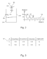
- Fig. 2 shows a typical application of such a device.
- the level gauge 201 emits a signal 203 via the antenna 202 in the direction of the medium 204 to be measured.
- the level gauge itself can determine the distance to the medium with the help of ultrasound, radar, laser or the principle of the guided microwave. Accordingly, both ultrasonic waves and electromagnetic waves come into consideration as signals.
- the medium 204 reflects the impinging wave back to the meter where it is received and processed.
- the radiated signal is also reflected by vessel installations, for example a built-in tube 205.
- the echo curve 206 received in the fill level measuring device 206 can thus contain, in addition to the fill level echo 207 caused by the fill level 204, also echoes 208 of permanently installed defects 205, which are referred to below as false echoes.
- the product container 209 has a cylindrical shape in the present example.
- the echo curve 206 is examined by the arithmetic unit 210 for echoes.
- an echo list 301 according to the scheme of FIG Fig. 3 generated.
- the echo list also contains another echo E1 or 207 generated by the medium 204.
- echo lists represent only a specific implementation of an echo list.
- echo lists are also common with other or changed features of an echo.
- the local progressions of the individual echoes of the echo list determined in the form of a track list are further processed in the block "motion detection" 104.
- the aim of this processing step is to make a statement about which echoes move over several measurements relative to their echo location, and which behave stationary with respect to the determined echo location.
- the methods used at this point can also be made according to the current state of the art and are, for example, in EP 10 156 793.1 described in detail.
- the amplitude adjuster 105 assumes a central role within the signal processing chain of the level gauge. It should be noted at this point that the logical division of the algorithmic steps to be performed according to Fig. 1 represents only one possible variant. In many cases, the same process steps are divided into differently defined blocks. For example, the functionality of the "amplitude adjuster" 105 may also be implemented within the "decision on level” 106.
- the task of the amplitude evaluator 105 is to evaluate the echoes of the currently present echo list 301 with regard to its current amplitude.
- the idea underlying this method step is derived from the general radar equation for the case of a radar level measuring device, which is described in detail, for example, in "Meinke / Gundlach: Taschenbuch der Hochfrequenztechnik". In the case of a level measurement with ultrasound or laser corresponding physical laws can be found in the relevant literature.
- the amplitude evaluator determines the theoretically expected echo amplitude for the various echoes of the echo list using mathematical equations, and compares these with the actually received amplitude of the respectively considered echo. If the actually received echo amplitude corresponds to the theoretically expected amplitude of a product reflection at the corresponding location, this relationship is transmitted in the form of a high amplitude evaluation of the corresponding echo to the decision to fill level 106. If the received amplitude deviates greatly from the echo amplitude to be expected from a product reflection, this leads to a low amplitude evaluation.
- the validity of the radar equation can be limited to reflectors which are located in the far field of a transmitting antenna. This condition is sufficiently fulfilled if and only if the distance between object and transmitter is significantly greater than the wavelength of the radar signal. In the present case of a level radar device with a wavelength of typically 5 cm, this condition is sufficiently fulfilled. In addition, it is required as a further prerequisite that the reflector to be measured is radiated over a large area by the transmitting lobe of the radar antenna used.
- Fig. 4 shows an untypical but basically possible application of a level measuring device in the context of object monitoring.
- the object 401 to be monitored is located at a sufficiently great distance from the measuring device 402, and is radiated over a large area by the transmitting lobe 403 of the radar antenna 404.
- the transmitting lobe of the radar antenna depends directly on the structure of the antenna, and can be determined with standard simulation programs for the particular type of antenna used with sufficient accuracy in advance.
- Fig. 5 a further arrangement for measuring the level of a medium 501 within a container 502 is shown. It can be seen directly from the illustration that the antenna lobe 505 belonging to the antenna 503 of the level measuring device 504 is not able to over-radiate the complete surface 506 of the reflecting medium 501 due to the small distance to the filling material. In addition, a transition into the near zone of the antenna can occur, in particular in the case of small containers, due to the resulting short distances to the filling material. Both effects lead to the fact that the amplitude reflected by the product can no longer be predicted with sufficient accuracy by the radar equation.
- the expected amplitude AL can be determined approximately in advance according to a function 507 which depends on the inverse distance d to the object, exponentiated with the exponent three 508 (AL ⁇ f (d -3 )).
- a function 507 which depends on the inverse distance d to the object, exponentiated with the exponent three 508 (AL ⁇ f (d -3 )).
- the function for calculating the expected reception amplitude depends in many respects on the geometry of the container 502, the dielectric constant of the medium 501 and also of the antenna 503 used, which results in relatively extensive input of parameters necessary.
- Fig. 6 shows a corresponding arrangement.
- Empirical observations suggest a course 602 of the expected amplitude values, which is a function 603 as a function of the inverse square distance of the reflector (AL ⁇ f (d -2 )).
- a ⁇ f (d -2 ) the inverse square distance of the reflector
- the present invention provides a suitable method for determining an expected value for the amplitude of the level echo generated by the product surface.
- Fig. 7 shown construction of a signal processing unit largely corresponds to the structure Fig. 1 , but differs by the newly added processing unit "Amplitude Profiler" 701 and the modified processing unit "Amplitude Evaluator” 702.
- the block "amplitude profiler” 701 is advantageously used.
- the task of this unit is to continuously monitor the level determined by the "decision on level” block in order to create a profile of the amplitude values of the level echo so far observed.
- This amplitude profile is made available to the amplitude evaluator 702, which in turn enables it to calculate the expected amplitude of the fill level echo at a specific amplitude profile on the basis of the transmitted amplitude profile Location to determine.
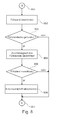
- Fig. 8 shows a flow chart for amplitude profiling in level gauges.
- the sequence shown is run through in each measuring cycle of the level measuring device.
- the method starts in start state 801.
- step 802 the current level is determined.
- almost all process steps of a conventional level measuring device are included.
- an echo curve is received in this step, and echoes are extracted.
- the echoes are then examined for movement.
- the amplitudes of the echoes in the amplitude evaluator 702 are evaluated by known methods.
- the amplitude profiler provides a curve with expected amplitude values, which can be firmly defined, for example, by default in the factory.
- a decision is calculated on the current level echo, and provided this level echo to the outside in a structured form.
- Fig. 10 shows an example of such a structure, which in addition to the location of the level echo also includes its amplitude and the reliability of the decision.
- step 803 the provided level echo information is examined by the amplitude profiler 701. If a valid level echo has been found, the program branches to step 804. Otherwise, the method ends directly in the end state 807.
- step 804 the reliability of the level echo information is considered. In other words, it is examined at this point whether the "decision on level" block 106 has made its selection of an echo as level echo with sufficiently high certainty.
- a measure of the security of the decision for example, in the structure in Fig. 10 included reliability of Decision, which can be derived, for example, from the signal-to-noise ratio of the level echo.
- a measure of the security of the decision can be according to another embodiment, the amount of movement of the level echo.
- step 806 the amplitude profile within the amplitude profiler 701 is now updated.
- the amplitude in advance contained in the main memory at the location of the current level echo is replaced within this process step by the amplitude of the current level echo.
- Fig. 9 shows by way of example the sequence steps of the method based on a filling of a container.
- the device is put into operation at the time t 0 .
- the level measuring device 901 may decide on the basis of the currently present echo curve 902 for the echo E3 or 903 as the current fill level.
- the amplitude profiler 701 adopts the echo amplitude of the fill level echo as a new interpolation point 904 in the amplitude profile 905 it manages.
- the echo E5 or 907 is identified as the fill level on the basis of the echo curve 906.
- the amplitude profiler 701 updates its amplitude profile 905 about the interpolation point 908 on the basis of this decision.
- the amplitude profile 905 is updated continuously at the times t 2 , t 3 , t 4 by supplementing by the interpolation points 909, 910, 911.
- the amplitude profiler has a completely learned amplitude profile 905 of the current application which can subsequently be used for the evaluation of echo lists.
- the learned amplitude profile is advantageously copied into a non-volatile memory area of the sensor in order to be immediately available again after a power failure when the device is restarted.
- the storage in the non-volatile memory area can be done in each measurement cycle, or even in a predefined time grid or event-controlled, for example, when changing the level.
- the proposed embodiment offers the advantage over the current state of the art of producing an exact, application-specific image of the amplitude of the fill level echo without requiring an external, user-initiated action.
- the once determined amplitude is reproduced with high accuracy again when reaching a certain filling level of the medium, as far as it is the medium in the container to a medium with a quiet surface.
- FIG. 11 clarifies the problem by means of a moving surface of a liquid.
- an amplitude of, for example, 70 dB is determined for the level echo EF0 1105, and stored by the amplitude profiler 701 in the amplitude profile 905 as a reference point.
- a trumpet 1103 will be formed instead of the flat liquid surface 1102, which will also move around the agitator 1101.
- the level measuring device 1104 will now detect an echo EF 1106 at an identical location, which due to the restless reflecting surface 1103 only has a reduced amplitude of, for example, 55 dB.
- the amplitude profiler 701 may now be modified in such a way that it is enabled to calculate a statistic with regard to the amplitude values of the level echo which have been transmitted to it.
- Fig. 12 shows the amplitude profile as it can be created by an amplitude profiler extended by the statistics calculation.
- the amplitude profile in the present example consists of the mean value curve 1202, which can be continuously calculated by forming the mean values of all fill level amplitudes at one position.
- the curve 1201 describes the maximum amplitude value of an echo detected at one location; the curve 1203 describes the minimum fill level amplitude value detected at one location.
- the amplitude evaluator 702 may now be given all three statistics curves 1201, 1202, 1203.
- An echo of the echo list is therefore given a high amplitude evaluation by the amplitude evaluator 702 if and only if its amplitude is in the range between the minimum curve 1203 and the maximum curve 1201.
- the method it may also be possible to derive the upper statistical curve 1201 and the lower statistical curve 1202 from other statistical relationships, for example the variance.
- the determined statistical values can be stored in the volatile and / or non-volatile memory area of a fill level measuring device. The storage can be done in each measurement cycle, or even in a pre-defined time frame or event-controlled, for example, when changing the level.
- Fig. 13 shows a particularly advantageous application of the method according to the invention with reference to a container 1301, which is to be filled completely by way of example.
- the standard blocking distance B 1302 which is typically 50 cm between filling level meter and the medium to be measured, is undercut in the case of level measuring instruments, this is generally referred to as overfilling of the container.
- This overfill represents an unspecified application of a level gauge, and must be prevented by the user in most cases. Background of this requirement is that in the range to, for example, 50 cm, a relatively strong reflection 1303 of the antenna of the level measuring device is received.
- a level gauge detects an inadmissible overfilling of a container, it can respond to it in a targeted manner. For example, it may be possible to output a level of 110% outwardly to notify the user that the container is overfilled. Furthermore, it may also be possible to output a disturbance current via a 4 to 20 mA interface to the user notify that the system is operated outside the current specification.
- the occurrence of an overfill situation can be stored persistently by the device in an event memory in order to facilitate a targeted problem analysis in the event of a possibly necessary service intervention.
- the level measuring device 1308 emits a signal in the direction of the product surface 1304 to be measured.
- the product is located in an upwardly closed container 1301.
- the echo curve 1309 subsequently received by the device contains, in addition to the reflection EL1 1305 caused by the product, a further reflection EM1 1310, which is caused by a multiple reflection medium - container cover - medium 1315. It is further assumed that in the previous operation of the level measuring device 1308 of the amplitude profiler 701 contained therein could already create an amplitude profile 1311 of the container.
- the amplitude profile 1311 of the container is also shown in the coordinate system of the echo curve representation.
- the received echo curve 1312 in turn includes an echo EL2 1306 caused by the product surface 1304 and an echo EM2 1313 caused by multiple reflection.
- the amplitude evaluator 702 when comparing the amplitude of the echo EM3 1314 with the expected amplitude of the amplitude profile 1311 at the location of the echo EM3 that they deviate very greatly from one another. Consequently, the echo EM3 can not be the echo caused by the product surface 1304. The level gauge can therefore automatically close to an overfilling of the container.
- the amplitude profile generated dynamically by the device opens up new possibilities for algorithmic evaluation.
- Fig. 14 shows an electronics unit 1400 according to an embodiment of the invention.
- the electronic unit has inter alia a computing unit 210, which is provided for determining the functional relationship.
- the arithmetic unit 210 is connected to a memory 1401.
- the memory 1401 has a non-volatile memory area 1403, in which, for example, the functional relationship, statistical characteristics for the level amplitude and / or other important information can be stored, which are then available even after a restart of the level gauge.
- the computing unit 210 is connected to the transmit / receive antenna arrangement 202.
- the antenna arrangement 202 transmits a transmission signal to the product surface 1304, which is reflected there and received as a reception signal 1405 from the antenna arrangement.
- a higher-level controller 1402 is provided, which is part of the electronic unit 1400 or at least connected to the electronic unit 1400. This higher-level control can support or control the arithmetic unit 210.
Landscapes
- Physics & Mathematics (AREA)
- Radar, Positioning & Navigation (AREA)
- Remote Sensing (AREA)
- Engineering & Computer Science (AREA)
- General Physics & Mathematics (AREA)
- Electromagnetism (AREA)
- Fluid Mechanics (AREA)
- Thermal Sciences (AREA)
- Computer Networks & Wireless Communication (AREA)
- Acoustics & Sound (AREA)
- Measurement Of Levels Of Liquids Or Fluent Solid Materials (AREA)
- Radar Systems Or Details Thereof (AREA)
- Measurement Of Velocity Or Position Using Acoustic Or Ultrasonic Waves (AREA)
Abstract
Description
Die vorliegende Erfindung bezieht sich auf ein Verfahren zur Messung von Füllständen aller Art, wie zum Beispiel Verfahren auf Basis von Ultraschallsignalen, Radarsignalen, Mikrowellensignalen oder Vibrationen. Insbesondere betrifft die Erfindung eine Elektronikeinheit für ein Füllstandmessgerät, ein Füllstandmessgerät mit einer Elektronikeinheit, eine Verwendung eines Füllstandmessgerätes, sowie ein Verfahren zur Füllstandmessung.The present invention relates to a method for measuring levels of all kinds, such as methods based on ultrasonic signals, radar signals, microwave signals or vibrations. In particular, the invention relates to an electronic unit for a level gauge, a level gauge with an electronic unit, a use of a level gauge, and a method for level measurement.
Peter Devine: "Füllstandmessung mit Radar - Leitfaden für die Prozessindustrie" beschreibt den grundsätzlichen Aufbau kommerzieller Radarfüllstandmessgeräte.Peter Devine: "Level Measurement with Radar - Guidelines for the Process Industry" describes the basic structure of commercial radar level gauges.
Empfangsverstärkers in Abhängigkeit von der Distanz zur Quelle des Signals verändert wird.Receive amplifier is changed in dependence on the distance to the source of the signal.
Meinke/Gundlach: "Taschenbuch der Hochfrequenztechnik" beschreibt die Vorgehensweise zur Voraussage der erwarteten Echoamplitude mit Hilfe der Radargleichung.Meinke / Gundlach: "Taschenbuch der Hochfrequenztechnik" describes the procedure for the prediction of the expected echo amplitude using the radar equation.
Die bekannten Verfahren sind oft aufwändig und teilweise ungenau.The known methods are often complex and sometimes inaccurate.
Es ist daher eine Aufgabe der vorliegenden Erfindung, ein Verfahren und eine zugehörige Vorrichtung anzugeben, welche es gestattet, den Füllstand mit hoher Genauigkeit zu bestimmen.It is therefore an object of the present invention to provide a method and associated apparatus which allows to determine the level with high accuracy.
Die Aufgabe wird durch die Merkmale der unabhängigen Patentansprüche gelöst. Weiterbildungen der Erfindung ergeben sich aus den Unteransprüchen.The object is solved by the features of the independent claims. Further developments of the invention will become apparent from the dependent claims.
Gemäß einem ersten Aspekt der Erfindung ist eine Elektronikeinheit für ein Füllstandmessgerät zur Bestimmung eines Füllstandes angegeben. Die Elektronikeinheit weist eine Recheneinheit auf, die zur Ermittlung eines funktionalen Zusammenhangs zwischen der Entfernung einer Füllgutoberfläche zu dem Füllstandmessgerät und einer Amplitude eines von der Füllgutoberfläche reflektierten und von dem Füllstandmessgerät empfangenen Signalanteils ausgeführt ist.According to a first aspect of the invention, an electronic unit for a level measuring device for determining a level is indicated. The electronic unit has an arithmetic unit which is designed to determine a functional relationship between the removal of a product surface from the level measuring device and an amplitude of a signal component reflected from the product surface and received by the level sensor.
Durch die Bestimmung des funktionalen Zusammenhangs zwischen dem Füllstand (der sich aus der Entfernung zwischen der Füllgutoberfläche und dem Füllstandmessgerät bestimmen lässt) und der Amplitude des empfangenen Signalanteils kann die Elektronikeinheit eine Wertung der (beispielsweise später) empfangenen Echos vornehmen. Insbesondere kann bestimmt werden, ob es sich bei einem bestimmten Echo um ein den Füllstand repräsentierendes Echo oder um ein Artefakt, also um ein "falsches" Echo handelt, welches beispielsweise auf eine Mehrfachreflexion im Behälter oder auf einen Behältereinbau zurückzuführen ist.By determining the functional relationship between the level (which can be determined from the distance between the product surface and the level meter) and the amplitude of the received signal component, the electronic unit can perform an evaluation of the received echo (for example, later). In particular, it can be determined whether a particular echo is an echo representing the fill level or an artifact, ie a "false" echo, which is due, for example, to a multiple reflection in the container or to a container installation.
Durch die Auswertung der Amplitude entsprechender empfangener Signalanteile der Echokurve kann somit die Wahrscheinlichkeit erhöht werden, dass das Füllstandecho korrekt identifiziert wird. Auch ist es möglich, einen Überfüllungszustand zu detektieren.By evaluating the amplitude of corresponding received signal components of the echo curve, it is thus possible to increase the probability that the fill level echo is correctly identified. It is also possible to detect a congestion state.
Gemäß einem Ausführungsbeispiel der Erfindung weist die Elektronikeinheit weiterhin einen Speicher auf, wobei der funktionale Zusammenhang zwischen dem Füllstand und der Amplitude des empfangenen Signalanteils in Form von Stützstellen im Speicher abgelegt wird.According to one embodiment of the invention, the electronic unit further comprises a memory, wherein the functional relationship between the level and the amplitude of the received signal component is stored in the form of nodes in the memory.
Auf Basis dieser Stützstellen kann eine Extrapolation erfolgen, um somit zu erwartende Amplituden (die Amplitude kann sich mit dem Füllstand ändern) vorauszusagen.On the basis of these interpolation points, extrapolation can be carried out in order to predict expected amplitudes (the amplitude may change with the level).
Gemäß einem weiteren Ausführungsbeispiel der Erfindung wird der funktionale Zusammenhang durch Anpassung der Koeffizienten in einer mathematischen Gleichung hergestellt.According to a further embodiment of the invention, the functional relationship is established by fitting the coefficients in a mathematical equation.
Auf diese Weise ist eine genaue Vorhersage zukünftig zu erwartender Amplitudenwerte möglich.In this way, an accurate prediction of future expected amplitude values is possible.
Gemäß einem weiteren Ausführungsbeispiel der Erfindung wird der funktionale Zusammenhang zur Bewertung der Echos einer Echoliste verwendet.According to another embodiment of the invention, the functional relationship is used to evaluate the echoes of an echo list.
Auch können zur Bewertung der Echos der Echoliste noch weitere Kriterien angelegt werden, beispielsweise Trendberechnungen, Erwartungsfenster, innerhalb denen der Füllstand mit hoher Wahrscheinlichkeit liegen sollte, oder andere Plausibilitätsüberlegungen.Also, other criteria can be applied to evaluate the echoes of the echo list, such as trend calculations, expectation windows, within which the level should be with high probability, or other plausibility considerations.
Gemäß einem weiteren Ausführungsbeispiel der Erfindung wird die Ermittlung des funktionalen Zusammenhangs nur dann durchgeführt, wenn das Füllstandmessgerät den Füllstand mit hoher Zuverlässigkeit identifiziert hat.According to a further embodiment of the invention, the determination of the functional relationship is only performed when the level gauge has identified the level with high reliability.
Somit kann vermieden werden, dass ein falscher Wert hinsichtlich des funktionalen Zusammenhangs zwischen dem Amplitudenwert und dem Füllstand für spätere Berechnungen verwendet wird.Thus it can be avoided that an incorrect value regarding the functional relationship between the amplitude value and the level is used for later calculations.
Gemäß einem weiteren Ausführungsbeispiel der Erfindung wird die Ermittlung des funktionalen Zusammenhangs nur dann durchgeführt, wenn sich das Echo der Füllgutoberfläche über mehrere Messzyklen hinweg in Bezug auf seine Position verändert.In accordance with a further exemplary embodiment of the invention, the determination of the functional relationship is only carried out if the echo of the product surface changes over several measuring cycles with respect to its position.
Auf diese Weise kann unnötige Rechenarbeit vermieden werden.In this way unnecessary computing work can be avoided.
Gemäß einem weiteren Ausführungsbeispiel der Erfindung wird bei der Ermittlung des funktionalen Zusammenhangs zumindest ein statistischer Kennwert für die Füllstandamplitude ermittelt.According to a further exemplary embodiment of the invention, at least one statistical characteristic value for the filling level amplitude is determined when determining the functional relationship.
Gemäß einem weiteren Ausführungsbeispiel der Erfindung wird der zumindest eine statistische Kennwert für die Füllstandamplitude zur Bewertung der Echos einer Echoliste verwendet.According to a further exemplary embodiment of the invention, the at least one statistical parameter for the level amplitude is used to evaluate the echoes of an echo list.
Auf diese Weise kann die Wahrscheinlichkeit, dass ein falsches Echo irrtümlich als Füllstandecho klassifiziert wird, reduziert werden.In this way, the probability that a false echo is erroneously classified as level echo can be reduced.
Gemäß einem weiteren Ausführungsbeispiel der Erfindung wird der funktionale Zusammenhang dazu verwendet, das Eintreten einer Überfüllsituation zu detektieren.According to a further embodiment of the invention, the functional relationship is used to detect the occurrence of an overfill situation.
Das Füllstandmessgerät kann somit automatisiert auf eine Überfüllung des Behälters schließen.The level gauge can thus automatically close an overfilling of the container.
Gemäß einem weiteren Ausführungsbeispiel der Erfindung wird das Eintreten der Überfüllsituation dem Benutzer und/oder einer übergeordneten Steuerung signalisiert.According to a further exemplary embodiment of the invention, the occurrence of the overfill situation is signaled to the user and / or to a higher-level control.
Gemäß einem weiteren Ausführungsbeispiel der Erfindung weist der Speicher einen nicht flüchtigen Speicherbereich auf. Das Eintreten einer Überfüllsituation, der funktionale Zusammenhang und/oder der zumindest eine statistische Kennwert für die Füllstandamplitude wird hierbei in dem nicht flüchtigen Speicherbereich abgelegt, nachdem der entsprechende Wert gewonnen wurde.According to a further embodiment of the invention, the memory has a non-volatile memory area. The occurrence of an overfill situation, the functional relationship and / or the at least one statistical characteristic value for the level amplitude is stored here in the non-volatile memory area after the corresponding value has been obtained.
Gemäß einem weiteren Ausführungsbeispiel der Erfindung wird innerhalb des Tracking insbesondere der Verlauf des Ortes eines Echos über mehrere Einzelmessungen hinweg verfolgt, und diese gesammelte Information wird in Form eines Tracks im nichtflüchtigen Speicherbereich abgelegt.According to a further embodiment of the invention, in particular the course of the location of an echo is tracked over several individual measurements within the tracking, and this collected information is stored in the form of a track in the non-volatile memory area.
Gemäß einem weiteren Ausführungsbeispiel der Erfindung werden die in dem nicht flüchtigen Speicherbereich abgelegten Informationen bei der Wiederinbetriebnahme des Messgeräts gelesen und zur Bewertung von Echos verwendet.According to a further embodiment of the invention, the information stored in the non-volatile memory area is read when the meter is restarted and used to evaluate echoes.
Somit kann auch bei einem Neustart des Messgeräts sichergestellt werden, dass die Echos einer Echokurve korrekt klassifiziert werden bzw. dass der Füllstand korrekt berechnet wird.Thus, even when restarting the measuring device can be ensured that the echoes of an echo curve are classified correctly or that the level is calculated correctly.
Gemäß einem zweiten Aspekt der Erfindung ist ein Füllstandmessgerät mit einer oben und im Folgenden beschriebenen Elektronikeinheit angegeben.According to a second aspect of the invention, a level gauge is specified with an electronics unit described above and below.
Gemäß einem weiteren Aspekt der Erfindung ist die Verwendung eines Füllstandmessgeräts mit einer oben und im Folgenden beschriebenen Elektronikeinheit in einer Anwendung, in welcher eine Überfüllung eintreten kann, angegeben.According to a further aspect of the invention, the use of a level gauge with an electronics unit described above and below in an application in which overfilling may occur is indicated.
Gemäß einem weiteren Aspekt der Erfindung ist ein Verfahren zur Bestimmung eines Füllstandes mit einem Füllstandmessgerät angegeben. Bei dem Verfahren erfolgt ein Aussenden eines Sendesignals zu einer Füllgutoberfläche. Daraufhin wird ein mit dem Sendesignal korrespondierendes Empfangssignal von einer entsprechenden Empfangseinrichtung des Füllstandmessgeräts detektiert. Daraufhin erfolgt eine Ermittlung des funktionalen Zusammenhangs zwischen der Entfernung zwischen der Füllgutoberfläche und dem Füllstandmessgerät und einer Amplitude eines von der Füllgutoberfläche reflektierten und von dem Füllstandmessgerät empfangenen Signalanteils des Empfangssignals.According to a further aspect of the invention, a method for determining a level with a level gauge is specified. In the method, a transmission signal is emitted to a product surface. Then, a received signal corresponding to the transmission signal is detected by a corresponding receiving device of the level measuring device. This is followed by a determination of the functional relationship between the distance between the filling material surface and the filling level measuring device and an amplitude of a signal component of the received signal which is reflected by the filling material surface and received by the filling level measuring device.
An dieser Stelle sei zu bemerken, dass die oben und im Folgenden beschriebenen Merkmale jeweils sowohl für die Elektronikeinheit, das Füllstandmessgerät, die Verwendung und für das Verfahren gelten können. In anderen Worten lassen sich beispielsweise diejenigen Merkmale, die oben und im Folgenden im Hinblick auf die Elektronikeinheit beschrieben werden, auch als Verfahrensschritte implementieren, und umgekehrt.It should be noted at this point that the features described above and below can apply to both the electronic unit, the level meter, the use and the method. In other words, for example, those features that are described above and below with regard to Electronic unit can be described, also implement as process steps, and vice versa.
Im Folgenden werden mit Verweis auf die Figuren Ausführungsbeispiele der Erfindung beschrieben.In the following, embodiments of the invention will be described with reference to the figures.
-
Fig. 1 zeigt eine Vorrichtung zur Echosignalverarbeitung, beispielsweise eine Elektronikeinheit.Fig. 1 shows a device for echo signal processing, for example an electronic unit. -
Fig. 2 zeigt ein Füllstandmessgerät zur Messung eines Füllstands in einem Behälter gemäß einem Ausführungsbeispiel der Erfindung, sowie eine entsprechende Echokurve.Fig. 2 shows a level gauge for measuring a level in a container according to an embodiment of the invention, as well as a corresponding echo curve. -
Fig. 3 zeigt eine Echoliste eines Füllstandmessgeräts.Fig. 3 shows an echo list of a level gauge. -
Fig. 4 zeigt ein Füllstandmessgerät in der Objektüberwachung sowie einen funktionalen Zusammenhang gemäß einem Ausführungsbeispiel der Erfindung.Fig. 4 shows a level gauge in the object monitoring and a functional relationship according to an embodiment of the invention. -
Fig. 5 zeigt ein Füllstandmessgerät bei der Messung von Flüssigkeiten sowie einen entsprechenden funktionalen Zusammenhang gemäß einem Ausführungsbeispiel der Erfindung.Fig. 5 shows a level gauge in the measurement of liquids and a corresponding functional relationship according to an embodiment of the invention. -
Fig. 6 zeigt ein Füllstandmessgerät bei der Messung von Schüttgütern, sowie einen entsprechenden funktionalen Zusammenhang gemäß einem weiteren Ausführungsbeispiel der Erfindung.Fig. 6 shows a level gauge in the measurement of bulk solids, as well as a corresponding functional relationship according to another embodiment of the invention. -
Fig. 7 zeigt eine Vorrichtung zur Echosignalverarbeitung, beispielsweise in Form einer Elektronikeinheit, gemäß einem Ausführungsbeispiel der Erfindung.Fig. 7 shows a device for echo signal processing, for example in the form of an electronic unit, according to an embodiment of the invention. -
Fig. 8 zeigt ein Ablaufdiagramm zur Füllstandmessung.Fig. 8 shows a flow chart for level measurement. -
Fig. 9 zeigt eine Amplitudenprofilierung bei ruhiger Füllgutoberfläche gemäß einem Ausführungsbeispiel der Erfindung.Fig. 9 shows an amplitude profiling with quiet Füllgutoberfläche according to an embodiment of the invention. -
Fig. 10 zeigt eine Füllstandecho-Struktur.Fig. 10 shows a level echo structure. -
Fig. 11 zeigt Echosignale bei unruhiger Füllgutoberfläche.Fig. 11 shows echo signals in case of an unstable product surface. -
Fig. 12 zeigt drei Amplitudenprofile gemäß einem weiteren Ausführungsbeispiel der Erfindung.Fig. 12 shows three amplitude profiles according to another embodiment of the invention. -
Fig. 13 zeigt Beispiele für die Füllstandmessung mit übervollem Behälter.Fig. 13 shows examples of level measurement with overfull container. -
Fig. 14 zeigt eine Elektronikeinheit gemäß einem weiteren Ausführungsbeispiel der Erfindung.Fig. 14 shows an electronic unit according to another embodiment of the invention.
Die Darstellungen in den Figuren sind schematisch und nicht maßstäblich.The illustrations in the figures are schematic and not to scale.
In der folgenden Figurenbeschreibung werden für die gleichen oder ähnlichen Elemente die gleichen Bezugsziffern verwendet.In the following description of the figures, the same reference numerals are used for the same or similar elements.
Bei den nach dem FMCW oder Impuls - Laufzeitverfahren arbeitenden Füllstandsensoren werden elektromagnetische oder akustische Wellen in Richtung einer Füllgutoberfläche emittiert. Daran anschließend zeichnet der Sensor die vom Füllgut und den Behältereinbauten reflektierten Echosignale auf, und leitet daraus den jeweiligen Füllstand ab.In the case of fill level sensors operating according to the FMCW or pulse transit time method, electromagnetic or acoustic waves are emitted in the direction of a product surface. Subsequently, the sensor records the reflected echo signals from the filling material and the vessel installations and deduces the respective filling level.
Im Block "Echokurvenaufbereitung" 101 sind alle Hard- und Softwareeinheiten enthalten, die benötigt werden, um eine Echokurve als Abbild der aktuellen Reflexionsverhältnisse innerhalb eines Behälters bereitzustellen. Die Echokurve wird vorzugsweise in digitaler Form innerhalb eines Mikroprozessorsystems erfasst, und mit Hilfe bekannter Verfahren auf darin enthaltene Echos untersucht.The block "Echo curve processing" 101 contains all the hardware and software units that are needed to provide an echo curve as an image of the current reflection conditions within a container. The echo curve is preferably detected in digital form within a microprocessor system, and examined for any echoes contained therein by known methods.
Die innerhalb des Blocks "Echoextraktion" 102 zu diesem Zweck angewendeten Verfahren umfassen insbesondere Verfahren aus dem Bereich der schwellwertbasierenden Echoextraktion oder auch Verfahren auf Basis einer skalenbasierenden Echoextraktion. Nach Abarbeitung des Echoextraktionsverfahrens wird eine digitale Echoliste bereitgestellt, die vorzugsweise Angaben zu Anfang, Ort, Ende und Amplitude eines oder mehrerer in der Echokurve enthaltenen Echos beinhaltet.The methods used within the "echo extraction"
Um die Zuverlässigkeit der Echosignalverarbeitung eines Füllstandmessgerätes weiter zu erhöhen, werden die gefundenen Echos innerhalb des Blocks "Tracking" 103 in einen historischen Kontext gestellt. Innerhalb des Tracking wird insbesondere der Verlauf des Ortes eines Echos über mehrere Einzelmessungen hinweg verfolgt, und diese gesammelte Information in Form eines Tracks im flüchtigen Speicher abgelegt. Diese Daten (Track) können gemäß einem Ausführungsbeispiel der Erfindung auch in einem nichtflüchtigen Speicherbereich abgelegt werden. Die gesammelten Historieninformationen mehrerer Echos werden in Form einer Trackliste nach außen hin bereitgestellt.
Aufbauend auf der übergebenen Trackliste wird im Block "Bewegungserkennung" 104 eine Analyse der Trackliste auf kontinuierliche Veränderungen eines Echokennwertes, beispielsweise des Echoortes, durchgeführt. Die Ergebnisse dieser Analyse werden in Form von Bewegungswerten, welche mit den aktuellen Echos der Echoliste korrespondieren, nach außen hin bereitgestellt.In order to further increase the reliability of the echo signal processing of a level gauge, the found echoes within the block "tracking" 103 are placed in a historical context. In particular, the tracking of the location of an echo over several individual measurements is tracked within the tracking, and this collected information is stored in the form of a track in the volatile memory. This data (track) can also be stored in a non-volatile memory area according to an embodiment of the invention. The collected history information of several echoes are provided to the outside in the form of a track list.
Based on the transferred track list, an analysis of the track list for continuous changes of an echo parameter, for example the echo location, is carried out in the block "motion detection" 104. The results of this Analysis is provided to the outside in the form of motion values which correspond to the echo list's current echoes.
Die Echos der Echoliste, welche von der Echoextraktion 102 bereitgestellt wird, werden im Block "Amplitudenbewerter" 105 weiter untersucht. Der Amplitudenbewerter 105 ermittelt für jedes Echo der Echoliste den Echoort, und berechnet die am Ort des Echos theoretisch zu erwartende Echoamplitude. Entspricht die Amplitude des Echos exakt der erwarteten Echoamplitude, so wird dem Echo eine hohe Amplitudenbewertung zugewiesen. Weicht die real vorhandene Amplitude des Echos jedoch stark von der zuvor errechneten, erwarteten Idealamplitude ab, so wird dem Echo eine Amplitudenbewertung von null zugeordnet.The echoes of the echo list provided by the
Im Block "Entscheidung auf Füllstand" 106 werden die Daten der aktuellen Echoliste, die dazu ermittelten Bewegungswerte der Echos und die Ergebnisse der Amplitudenbewertung miteinander abgeglichen. Im Idealfall zeichnet sich das von einer Füllgutoberfläche erzeugte Echo gerade dadurch aus, dass es unter der Vielzahl an Echos der Echoliste das Echo mit der größten Amplitudenbewertung ist.
Um die Genauigkeit der Füllstandmessung weiter zu verbessern, kann die Position des bestimmten Füllstandechos durch den optionalen Block "exakte Vermessung des Füllstandechos" 107 unter Anwendung rechenzeitintensiver Verfahren, beispielsweise Interpolationsverfahren, mit hoher Genauigkeit bestimmt werden. Die bestimmte Distanz zum Füllstand wird nach außen hin bereitgestellt. Die Bereitstellung kann in analoger Form (4..20 mA Schnittstelle) oder auch in digitaler Form (Feldbus) realisiert werden.In the block "Decision on level" 106, the data of the current echo list, the movement values of the echoes and the results of the amplitude evaluation determined therefor are compared with one another. Ideally, the echo produced by a product surface is characterized precisely by the fact that among the multiplicity of echoes of the echo list it is the echo with the largest amplitude evaluation.
In order to further improve the accuracy of the level measurement, the position of the particular level echo can be determined with high accuracy by the optional block "exact measurement of the level echo" 107 using computationally intensive methods, for example interpolation methods. The specific distance to the level is provided to the outside. The provision can be realized in analogue form (4..20 mA interface) or also in digital form (fieldbus).
Die Vorteile der vorliegenden Erfindung ergeben sich aus den speziellen Randbedingungen, denen die Echosignalverarbeitung innerhalb eines Füllstandmessgerätes unterliegt.
Es sei an dieser Stelle darauf hingewiesen, dass sämtliche Pegel im vorliegenden Text und in den zugehörigen Figuren als Relativpegel zu verstehen sind. Der Absolutpegel, welcher als Bezugsgröße für die Berechnung der Relativpegel verwendet wird, hat auf die Funktionsweise der vorliegenden Erfindung keinerlei Einfluss.It should be noted at this point that all levels in the present text and in the associated figures are to be understood as a relative level. The absolute level used as a reference for calculating the relative levels has no bearing on the operation of the present invention.
Das Füllstandmessgerät 201 strahlt über die Antenne 202 ein Signal 203 in Richtung des zu vermessenden Mediums 204 ab. Das Füllstandmessgerät selbst kann mit Hilfe von Ultraschall, Radar, Laser oder dem Prinzip der geführten Mikrowelle die Distanz zum Medium ermitteln. Als Signale kommen dementsprechend sowohl Ultraschallwellen als auch elektromagnetische Wellen in Betracht. Das Medium 204 reflektiert die auftreffende Welle zurück zum Messgerät, wo diese empfangen und verarbeitet wird. Gleichzeitig wird das abgestrahlte Signal auch von Behältereinbauten, beispielsweise einem eingebauten Rohr 205 reflektiert. Die im Füllstandmessgerät 201 empfangene Echokurve 206 kann somit neben dem vom Füllstand 204 hervorgerufenen Füllstandecho 207 auch Echos 208 von fest eingebauten Störstellen 205 enthalten, welche nachfolgend als Störechos bezeichnet werden. Der Füllgutbehälter 209 besitzt im vorliegenden Beispiel eine zylindrische Form.The
Innerhalb der nun anlaufenden Signalverarbeitung wird die Echokurve 206 durch die Recheneinheit 210 gezielt auf Echos hin untersucht. Als Ergebnis der Echoextraktion 102 wird eine Echoliste 301 nach dem Schema der
Selbstverständlich stellen die dargestellten Merkmale der Echoliste lediglich eine spezielle Implementierung einer Echoliste dar. In der Praxis sind auch Echolisten mit weiteren oder veränderten Merkmalen eines Echos gebräuchlich.Of course, the illustrated features of the echo list represent only a specific implementation of an echo list. In practice, echo lists are also common with other or changed features of an echo.
Aufbauend auf der erzeugten Echoliste 301 kommen im weiteren Verfahrensablauf spezialisierte Algorithmen zum Einsatz, welche die Möglichkeit eröffnen, den Verlauf des Ortes einzelner Echos über mehrere Messungen hinweg zu verfolgen. Die dazu verwendeten Verfahren können gemäß dem gegenwärtigen Stand der Technik erfolgen und sind in der einschlägigen Literatur unter dem Begriff "Tracking" ausführlich beschrieben.Based on the generated
Nach Abschluss des Tracking 103 werden die in Form einer Trackliste ermittelten örtlichen Verläufe der einzelnen Echos der Echoliste im Block "Bewegungserkennung" 104 weiter verarbeitet. Ziel dieses Verarbeitungsschrittes ist, eine Aussage darüber zu treffen, welche Echos sich über mehrere Messungen hinweg bezogen auf ihren Echoort bewegen, und welche sich in Bezug auf den ermittelten Echoort stationär verhalten. Die an dieser Stelle verwendeten Verfahren können ebenfalls gemäß dem aktuellen Stand der Technik erfolgen und sind beispielweise in
Mit Hilfe der ermittelten Bewegungswerte fällt es nun leicht, das vom Füllgut 204 erzeugte Echo der Echoliste 301 zu identifizieren, zeigt dieses doch nach erfolgter Befüllung oder Entleerung einen ausgeprägten Bewegungswert, wohingegen die Werte der ermittelten Orte der Echos der Störstelle 205 eine ausgeprägte Stationarität besitzen.With the aid of the determined movement values, it is now easy to identify the echo of the
Probleme kann dieses Verfahren jedoch im Einschaltmoment und in der Zeitspanne bis zur ersten Befüllung oder Entleerung des Behälters bereiten. Da ohne merkliche Änderung der Füllhöhe im Behälter keines der vorhandenen Echos eine ausgeprägte Bewegung zeigt, werden von der Bewegungserkennung alle Echos der Echoliste als stationär eingestuft. Eine Entscheidung, welches der identifizierten Echos das vom Füllgut 204 verursachte Echo ist, ist ohne weitere Informationen nicht möglich.However, this process can cause problems at the moment of switch-on and in the period until the first filling or emptying of the container. Since no noticeable change in the filling level in the container of any of the existing echoes shows a pronounced movement, all echoes of the echo list are classified as stationary by the motion detection. A decision which of the identified echoes is the echo caused by the filling
In solchen Fällen übernimmt der Amplitudenbewerter 105 eine zentrale Rolle innerhalb der Signalverarbeitungskette des Füllstandmessgerätes. Es sei an dieser Stelle darauf hingewiesen, dass die logische Aufteilung der durchzuführenden algorithmischen Schritte gemäß
Dem Amplitudenbewerter 105 obliegt die Aufgabe, die Echos der aktuell vorliegenden Echoliste 301 im Hinblick auf ihre aktuelle Amplitude zu bewerten. Die diesem Verfahrensschritt zu Grunde liegende Idee wird für den Fall eines Radarfüllstandmessgerätes aus der allgemeinen Radargleichung abgeleitet, welche beispielsweise in "Meinke/Gundlach: Taschenbuch der Hochfrequenztechnik" ausführlich beschrieben wird. Für den Fall einer Füllstandmessung mit Ultraschall oder Laser können entsprechende physikalische Gesetzmäßigkeiten aus der einschlägigen Literatur entnommen werden.The task of the
So ist es beispielsweise mit Hilfe der Radargleichung möglich, den Empfangspegel des Echos eines Objektes in einer vorab bekannten Entfernung bei bekanntem Sendepegel im Voraus zu berechnen. Der Amplitudenbewerter ermittelt für die verschiedenen Echos der Echoliste unter Verwendung mathematischer Gleichungen die theoretisch zu erwartende Echoamplitude, und vergleicht diese mit der tatsächlich empfangenen Amplitude des jeweils betrachteten Echos. Entspricht die tatsächlich empfangene Echoamplitude der theoretisch zu erwartenden Amplitude einer Füllgutreflexion an der entsprechenden Stelle, so wird dieser Zusammenhang in Form einer hohen Amplitudenbewertung des entsprechenden Echos an die Entscheidung auf Füllstand 106 übermittelt. Weicht die empfangene Amplitude stark von der von einer Füllgutreflexion zu erwartenden Echoamplitude ab, so führt dies zu einer niedrigen Amplitudenbewertung.Thus, for example, with the aid of the radar equation, it is possible to calculate in advance the reception level of the echo of an object at a previously known distance at a known transmission level. The amplitude evaluator determines the theoretically expected echo amplitude for the various echoes of the echo list using mathematical equations, and compares these with the actually received amplitude of the respectively considered echo. If the actually received echo amplitude corresponds to the theoretically expected amplitude of a product reflection at the corresponding location, this relationship is transmitted in the form of a high amplitude evaluation of the corresponding echo to the decision to fill
Innerhalb der Entscheidung auf Füllstand 106 kann nun auch im Moment des Einschaltens des Füllstandmessgerätes oder bei fehlender Bewegung eine sichere Identifikation des Füllstandechos realisiert werden, indem beispielsweise genau dasjenige Echo der Echoliste 301 als Füllstandecho identifiziert wird, dessen Amplitudenbewertung am höchsten ist.Within the decision on
Das zuvor beschriebene Verfahren der Amplitudenbewertung führt in der praktischen Anwendung immer wieder zu Problemen.The above-described method of amplitude evaluation always leads to problems in practical application.
Grundsätzlich kann die Gültigkeit der Radargleichung auf Reflektoren beschränkt sein, welche sich im Fernfeld einer Sendeantenne befinden. Diese Bedingung ist genau dann hinreichend erfüllt, wenn die Entfernung zwischen Objekt und Sender deutlich größer als die Wellenlänge des Radarsignals ist. Im vorliegenden Fall eines Füllstandradargerätes mit einer Wellenlänge von typischerweise 5 cm ist diese Bedingung hinreichend erfüllt. Zudem wird als weitere Voraussetzung verlangt, dass der zu messende Reflektor von der Sendekeule der verwendeten Radarantenne großflächig überstrahlt wird.In principle, the validity of the radar equation can be limited to reflectors which are located in the far field of a transmitting antenna. This condition is sufficiently fulfilled if and only if the distance between object and transmitter is significantly greater than the wavelength of the radar signal. In the present case of a level radar device with a wavelength of typically 5 cm, this condition is sufficiently fulfilled. In addition, it is required as a further prerequisite that the reflector to be measured is radiated over a large area by the transmitting lobe of the radar antenna used.
In
Noch schwieriger können sich die Verhältnisse bei der Messung von Schüttgütern 601 gestalten.
Alle zuvor beschriebene Verfahren zur Ermittlung der erwarteten Echoamplitude an einem vorgebbaren Ort können nur nach entsprechender Parametrierung des Gerätes angewendet werden, und führen selbst dann nur zu ungenauen Ergebnissen. Die beispielhaft dargestellten Nachteile bei der Vorausberechnung der erwarteten Echoamplitude des Füllstandechos treten auch bei der Verwendung von anderen Messverfahren auf. So wird beispielsweise bei der Messung mit Ultraschall die real empfangene Echoamplitude des Füllstandechos durch Staubanteile in der Behälteratmosphäre stark gedämpft, und weicht damit stark von der erwarteten Idealamplitude des Füllstandechos ab.All previously described methods for determining the expected echo amplitude at a predeterminable location can be used only after appropriate parameterization of the device, and lead to only inaccurate results even then. The disadvantages exemplified in the prediction of the expected echo amplitude of the level echo also occur when using other measuring methods. Thus, for example, when measuring with ultrasound the real received echo amplitude of the level echo is strongly attenuated by dust in the container atmosphere, and thus deviates greatly from the expected ideal amplitude of the level echoes.
Die vorliegende Erfindung schafft ein geeignetes Verfahren zur Bestimmung eines Erwartungswertes für die Amplitude des von der Füllgutoberfläche erzeugten Füllstandechos.The present invention provides a suitable method for determining an expected value for the amplitude of the level echo generated by the product surface.
Der in
Es ist eine zentrale Idee der vorliegenden Erfindung, die fehlerträchtige und aufwendige Bestimmung der erwarteten Amplitude des Füllstandechos an einer bestimmten Stelle nicht mit Hilfe mathematischer Gleichungen zu realisieren, sondern diese durch automatisch erworbenes Applikationswissen innerhalb des Füllstandmessgerätes zu ersetzen. Hierzu wird der Block "Amplitudenprofilierer" 701 vorteilhaft verwendet. Aufgabe dieser Einheit ist es, den vom Block "Entscheidung auf Füllstand" bestimmten Füllstand fortlaufend zu überwachen, um daraus ein Profil der bislang beobachteten Amplitudenwerte des Füllstandechos zu erstellen. Dieses Amplitudenprofil wird dem Amplitudenbewerter 702 zur Verfügung gestellt, was diesen wiederum in die Lage versetzt, anhand des übergebenen Amplitudenprofils die erwartete Amplitude des Füllstandechos an einem bestimmten Ort zu ermitteln.It is a central idea of the present invention not to realize the error-prone and expensive determination of the expected amplitude of the fill level echo at a specific location with the aid of mathematical equations, but to replace this with automatically acquired application knowledge within the fill level measuring device. For this purpose, the block "amplitude profiler" 701 is advantageously used. The task of this unit is to continuously monitor the level determined by the "decision on level" block in order to create a profile of the amplitude values of the level echo so far observed. This amplitude profile is made available to the
Im Schritt 803 wird die bereitgestellte Füllstandechoinformation vom Amplitudenprofilierer 701 untersucht. Wurde ein gültiges Füllstandecho gefunden, so wird in den Schritt 804 verzweigt. Ansonsten endet das Verfahren direkt im Endezustand 807.In
Im Schritt 804 wird die Zuverlässigkeit der Füllstandechoinformation betrachtet. Mit anderen Worten wird an dieser Stelle untersucht, ob der Block "Entscheidung auf Füllstand" 106 seine Auswahl eines Echos als Füllstandecho mit hinreichend großer Sicherheit getroffen hat. Ein Maß für die Sicherheit der Entscheidung kann beispielsweise die in der Struktur in
Wurde das Füllstandecho zuverlässig identifiziert, so wird in den Verfahrensschritt 806 verzweigt. Ansonsten endet das Verfahren im Endezustand 807.If the level echo has been reliably identified, branching is made to
Im Schritt 806 wird nun das Amplitudenprofil innerhalb des Amplitudenprofilierers 701 aktualisiert. Die vorab im Arbeitsspeicher enthaltene Amplitude an der Stelle des aktuellen Füllstandechos wird innerhalb dieses Verfahrensschrittes durch die Amplitude des aktuellen Füllstandechos ersetzt. Zudem mag es möglich sein, den neu erfassten Amplitudenwert in einem nichtflüchtigen Speicher persistent abzulegen.In
Es sei an dieser Stelle darauf hingewiesen, dass gemäß einem weiteren Ausführungsbeispiel ggf. fehlende Bereiche des Amplitudenprofils durch werksseitig definierte Standardwerte ersetzt werden können. Somit ist es möglich, das Amplitudenprofil 905 zu jedem der Zeitpunkte t0 bis t4 dem Amplitudenbewerter 702 zur Verfügung zu stellen.It should be noted at this point that, according to a further embodiment, possibly missing regions of the amplitude profile can be replaced by factory-defined default values. Thus, it is possible to provide the
Gemäß einem weiteren Ausführungsbeispiel ist es auch möglich, fehlende Amplitudenwerte bei Vorhandensein bereits erlernter Stützstellen zu interpolieren, oder durch Anpassung der Parameter vorab definierter mathematischer Gleichungen (beispielsweise der Radargleichung) zu berechnen.According to a further embodiment, it is also possible to interpolate missing amplitude values in the presence of already learned support points, or to calculate by adaptation of the parameters of previously defined mathematical equations (for example the radar equation).
Das erlernte Amplitudenprofil wird vorteilhafterweise in einen nichtflüchtigen Speicherbereich des Sensors kopiert, um nach einem Stromausfall bei der Wiederinbetriebnahme des Gerätes unmittelbar wieder zur Verfügung zu stehen. Die Speicherung im nichtflüchtigen Speicherbereich kann in jedem Messzyklus, oder aber auch in einem vorab definierten Zeitraster oder ereignisgesteuert, beispielsweise bei Veränderung der Füllhöhe, erfolgen.The learned amplitude profile is advantageously copied into a non-volatile memory area of the sensor in order to be immediately available again after a power failure when the device is restarted. The storage in the non-volatile memory area can be done in each measurement cycle, or even in a predefined time grid or event-controlled, for example, when changing the level.
Die vorgeschlagene Ausführungsform bietet gegenüber dem aktuellen Stand der Technik den Vorteil, ein exaktes, applikationsspezifisches Abbild der Amplitude des Füllstandechos zu erzeugen, ohne dass eine externe, benutzerinitiierte Aktion notwendig ist. Die einmal ermittelte Amplitude wird bei erneutem Erreichen einer bestimmten Füllhöhe des Mediums mit hoher Genauigkeit so wieder reproduziert, soweit es sich bei dem Medium im Behälter um ein Medium mit einer ruhigen Oberfläche handelt.The proposed embodiment offers the advantage over the current state of the art of producing an exact, application-specific image of the amplitude of the fill level echo without requiring an external, user-initiated action. The once determined amplitude is reproduced with high accuracy again when reaching a certain filling level of the medium, as far as it is the medium in the container to a medium with a quiet surface.
Andere Verhältnisse ergeben sich bei bewegten Oberflächen von Flüssigkeiten oder mit den unterschiedlich profilierten Oberflächen der Schüttlagen eines Schüttgutes.
Gemäß einer weiteren Ausgestaltung des Verfahrens mag daher der Amplitudenprofilierer 701 nun derart modifiziert werden, dass er in die Lage versetzt wird, eine Statistik bezüglich der ihm übergebenen Amplitudenwerte des Füllstandechos zu berechnen.According to a further embodiment of the method, therefore, the
Gemäß einer weiteren Ausgestaltung des Verfahrens mag es auch möglich sein, die obere Statistikkurve 1201 und die untere Statistikkurve 1202 aus anderen statistischen Zusammenhängen, beispielsweise der Varianz, abzuleiten. Selbstverständlich können die ermittelten Statistikwerte im flüchtigen und/oder nichtflüchtigen Speicherbereich eines Füllstandmessgerätes gespeichert werden. Die Speicherung kann in jedem Messzyklus, oder aber auch in einem vorab definierten Zeitraster oder ereignisgesteuert, beispielsweise bei Veränderung der Füllhöhe, erfolgen.According to a further embodiment of the method, it may also be possible to derive the upper
Unabhängig von diesen Randbedingungen ist es im Hinblick auf ASSET-Services ein erklärtes Ziel, eine Uberfüllungssituation innerhalb eines Behälters sicher erfassen zu können. Detektiert ein Füllstandmessgerät eine unzulässige Überfüllung eines Behälters, so kann es gezielt darauf reagieren. Beispielsweise mag es möglich sein, einen Füllstand von 110% nach außen hin auszugeben, um dem Anwender mitzuteilen, dass der Behälter überfüllt ist. Weiterhin mag es auch möglich sein, über eine 4 bis 20 mA Schnittstelle einen Störstrom auszugeben, um dem Anwender mitzuteilen, dass die Anlage außerhalb der gültigen Spezifikation betrieben wird. Zudem kann das Eintreten einer Überfüllsituation vom Gerät in einem Ereignisspeicher persistent gespeichert werden, um bei einem eventuell notwendigen Serviceeinsatz eine gezielte Problemanalyse zu erleichtern.
Regardless of these boundary conditions, it is a declared goal with regard to ASSET services to be able to reliably detect a crowding situation within a container. If a level gauge detects an inadmissible overfilling of a container, it can respond to it in a targeted manner. For example, it may be possible to output a level of 110% outwardly to notify the user that the container is overfilled. Furthermore, it may also be possible to output a disturbance current via a 4 to 20 mA interface to the user notify that the system is operated outside the current specification. In addition, the occurrence of an overfill situation can be stored persistently by the device in an event memory in order to facilitate a targeted problem analysis in the event of a possibly necessary service intervention.
Die Mechanismen, welche die Anwendung der vorliegenden Erfindung im Umfeld einer Überfüllungserkennung besonders vorteilhaft erscheinen lassen, werden mit Bezug auf
Zum Zeitpunkt t0 emittiert das Füllstandmessgerät 1308 ein Signal in Richtung der zu vermessenden Füllgutoberfläche 1304. Das Füllgut befindet sich in einem nach oben hin geschlossenen Behälter 1301. Die anschließend vom Gerät empfangene Echokurve 1309 beinhaltet neben der vom Füllgut verursachten Reflektion EL1 1305 eine weitere Reflektion EM1 1310, welche durch eine Mehrfachreflexion Medium - Behälterdecke - Medium 1315 verursacht wird. Es sei weiterhin angenommen, dass im bisherigen Betrieb des Füllstandmessgerätes 1308 der darin enthaltene Amplitudenprofilierer 701 bereits ein Amplitudenprofil 1311 des Behälters erstellen konnte. Das Amplitudenprofil 1311 des Behälters wird ebenfalls im Koordinatensystem der Echokurvendarstellung gezeigt. Es ist deutlich zu sehen, dass das Füllstandecho EL1 1305 exakt zum Amplitudenprofil 1311 des Amplitudenprofilierers 701 am Ort des Füllstandes von d = 4m passt.
Zum Zeitpunkt t1 wird ein weiterer Messzyklus des Füllstandmessgerätes initiiert. Die empfangene Echokurve 1312 beinhaltet wiederum ein Echo EL2 1306, welches von der Füllgutoberfläche 1304 verursacht wird, und ein Echo EM2 1313, welches durch eine Mehrfachreflektion verursacht wird. Es ist deutlich zu sehen, dass die Amplitude des Echos EL2 1306 exakt zum Amplitudenprofil 1311 des Amplitudenprofilierers 701 passt, wohingegen die Amplitude des Mehrfachechos EM2 1313 nicht zum Amplitudenprofil 1311 am Ort d = 4m passt.At the time t 0, the
At the time t 1 , a further measuring cycle of the level measuring device is initiated. The received
Zum Zeitpunkt t2 wird ein erneuter Messzyklus initiiert. Der Abstand zwischen dem Füllstandmessgerät 1308 und der Füllgutoberfläche 1304 zum Zeitpunkt t2 unterschreitet nun deutlich die vom Werk definierte Blockdistanz B 1302. Es ist daher nun nicht mehr möglich, innerhalb der empfangenen Echokurve 1307 die von der Füllgutoberfläche stammende Reflektion zu lokalisieren. Würde ein Gerät nach bisherigem Stand der Technik verwendet, würde stattdessen die Distanz zum Mehrfachecho EM3 1314 als gültige Entfernung zum Füllstand ausgegeben. Das Gerät wäre nicht in der Lage, die Überfüllung des Behälters zu detektieren. Wird stattdessen ein Gerät gemäß der vorliegenden Erfindung verwendet, so wird innerhalb des Amplitudenbewerters 702 beim Vergleich der Amplitude des Echos EM3 1314 mit der erwarteten Amplitude des Amplitudenprofils 1311 am Ort des Echos EM3 festgestellt, dass diese sehr stark voneinander abweichen. Folglich kann das Echo EM3 nicht das von der Füllgutoberfläche 1304 verursachte Echo sein. Das Füllstandmessgerät kann daher automatisiert auf eine Überfüllung des Behälters schließen.At time t 2 , a new measurement cycle is initiated. The distance between the
Weiterhin eröffnen sich durch das vom Gerät dynamisch erzeugte Amplitudenprofil neue Möglichkeiten der algorithmischen Auswertung.Furthermore, the amplitude profile generated dynamically by the device opens up new possibilities for algorithmic evaluation.
Beispielsweise kommen bei einer sehr großen Abweichung der Amplitude eines sicher identifizierten Füllstandechos vom erwarteten Wert oder bei einer kontinuierlichen Veränderung bereits erlernter Amplitudenwerte verschiedene Ursachen in Betracht. Zum einen könnte auf eine verschmutzte Antenne geschlossen werden. Weiterhin mag es möglich sein, einen Elektronikdefekt auf diese Art und Weise zu detektieren. Zudem kann auf die Bildung von Schaum innerhalb des Behälters geschlossen werden. Außerdem mag es möglich sein, Abschätzungen bezüglich der Dielektrizitätskonstanten des Mediums oder der Änderung der Dielektrizitätskonstanten bei Medienwechsel zu berechnen, da sich diese unmittelbar auf das Reflexionsvermögen und damit auf die Amplitude des Füllstandechos auswirken.For example, with a very large deviation of the amplitude of a reliably identified level echo from the expected value or with a continuous change of already learned amplitude values, different causes come into consideration. On the one hand could be closed to a polluted antenna. Furthermore, it may be possible to detect an electronic defect in this way. In addition, the formation of foam within the container can be concluded. In addition, it may be possible to calculate estimates of the dielectric constant of the medium or the change in dielectric constant during media changes, as these directly affect the reflectivity and thus the amplitude of the level echo.
Weiterhin ist die Recheneinheit 210 mit der Sende-/Empfangsantennenanordnung 202 verbunden. Die Antennenanordnung 202 sendet ein Sendesignal zur Füllgutoberfläche 1304 aus, welches dort reflektiert wird und als Empfangssignal 1405 von der Antennenanordnung aufgenommen wird.Furthermore, the
Weiterhin ist eine übergeordnete Steuerung 1402 vorgesehen, die Teil der Elektronikeinheit 1400 ist oder zumindest mit der Elektronikeinheit 1400 verbunden ist. Diese übergeordnete Steuerung kann die Recheneinheit 210 unterstützen oder steuern.Furthermore, a higher-
Ergänzend sei darauf hingewiesen, dass "umfassend" und "aufweisend" keine anderen Elemente oder Schritte ausschließt und "eine" oder "ein" keine Vielzahl ausschließt. Ferner sei darauf hingewiesen, dass Merkmale oder Schritte, die mit Verweis auf eines der obigen Ausführungsbeispiele beschrieben worden sind, auch in Kombination mit anderen Merkmalen oder Schritten anderer oben beschriebener Ausführungsbeispiele verwendet werden können. Bezugszeichen in den Ansprüchen sind nicht als Einschränkung anzusehen.In addition, it should be noted that "comprising" and "having" does not exclude other elements or steps, and "a" or "an" does not exclude a plurality. It should also be appreciated that features or steps described with reference to any of the above embodiments may also be used in combination with other features or steps of other embodiments described above. Reference signs in the claims are not to be considered as limiting.
Claims (15)
wobei der funktionale Zusammenhang (905) durch Anpassung der Koeffizienten einer mathematischen Gleichung (508, 603) hergestellt wird.Electronic unit (1400) according to claim 1,
wherein the functional relationship (905) is established by fitting the coefficients of a mathematical equation (508, 603).
wobei der funktionale Zusammenhang (905) zur Bewertung der Echos einer Echoliste (301) verwendet wird.Electronic unit (1400) according to one of claims 1 to 3,
wherein the functional relationship (905) is used to evaluate the echoes of an echo list (301).
wobei die Ermittlung des funktionalen Zusammenhangs (905) nur dann durchgeführt wird, wenn das Füllstandmessgerät den Füllstand mit hoher Zuverlässigkeit identifiziert.Electronic unit (1400) according to one of the preceding claims,
wherein the determination of the functional relationship (905) is performed only when the level gauge identifies the level with high reliability.
wobei die Ermittlung des funktionalen Zusammenhangs (905) nur dann durchgeführt wird, wenn sich das Echo (903, 907) der Füllgutoberfläche über mehrere Messzyklen hinweg in Bezug auf seine Position verändert.Electronic unit (1400) according to one of the preceding claims,
wherein the determination of the functional relationship (905) is performed only when the echo (903, 907) of the product surface over changed several measuring cycles with respect to its position.
wobei bei der Ermittlung des funktionalen Zusammenhangs (905) zumindest ein statistischer Kennwert (1201, 1202, 1203) für die Füllstandamplitude ermittelt wird.Electronic unit (1400) according to one of the preceding claims,
wherein when determining the functional relationship (905) at least one statistical characteristic value (1201, 1202, 1203) for the level amplitude is determined.
wobei der zumindest eine statistische Kennwert (1201, 1202, 1203) für die Füllstandamplitude zur Bewertung der Echos einer Echoliste (301) verwendet wird.Electronic unit (1400) according to claim 7,
wherein the at least one statistical characteristic value (1201, 1202, 1203) for the level amplitude is used to evaluate the echoes of an echo list (301).
wobei der funktionale Zusammenhang (905) dazu verwendet wird, das Eintreten einer Überfüllsituation zu detektieren.Electronic unit (1400) according to one of the preceding claims,
wherein the functional relationship (905) is used to detect the occurrence of an overfill situation.
wobei das Eintreten der Überfüllsituation dem Benutzer und / oder einer übergeordneten Steuerung (1402) signalisiert wird.Electronic unit (1400) according to claim 9,
wherein the occurrence of the overfill situation is signaled to the user and / or a higher level controller (1402).
wobei der Speicher (1401) einen nichtflüchtigen Speicherbereich (1403) aufweist;
wobei das Eintreten einer Überfüllsituation, der funktionale Zusammenhang (905), ein Track und / oder der zumindest eine statistischer Kennwert (1201, 1202, 1203) für die Füllstandamplitude in dem nichtflüchtigen Speicherbereich abgelegt wird.Electronic unit (1400) according to one of claims 2 to 10,
wherein the memory (1401) comprises a nonvolatile memory area (1403);
wherein the occurrence of an overfill situation, the functional relationship (905), a track and / or the at least one statistical characteristic value (1201, 1202, 1203) for the level amplitude is stored in the non-volatile memory area.
wobei die in dem nichtflüchtigen Speicherbereich (1403) abgelegten Informationen bei der Wiederinbetriebnahme des Messgerätes gelesen und zur Bewertung von Echos verwendet werden.Electronic unit (1400) according to claim 11,
wherein the information stored in the non-volatile memory area (1403) is read when the meter is restarted, and the Evaluation of echoes can be used.
Priority Applications (4)
| Application Number | Priority Date | Filing Date | Title |
|---|---|---|---|
| EP10170031.8A EP2418465B1 (en) | 2010-07-19 | 2010-07-19 | Amplitude profiling in fill level measuring devices |
| US13/182,636 US8776594B2 (en) | 2010-07-19 | 2011-07-14 | Amplitude profiling in filling-level measuring devices |
| CN201110204466.XA CN102338654B (en) | 2010-07-19 | 2011-07-15 | Article position measuring device and electronic unit thereof and the method for determining thing position |
| BRPI1103618-4A BRPI1103618B1 (en) | 2010-07-19 | 2011-07-18 | electronic unit, fill level measurement device and method for determining a fill level |
Applications Claiming Priority (1)
| Application Number | Priority Date | Filing Date | Title |
|---|---|---|---|
| EP10170031.8A EP2418465B1 (en) | 2010-07-19 | 2010-07-19 | Amplitude profiling in fill level measuring devices |
Publications (2)
| Publication Number | Publication Date |
|---|---|
| EP2418465A1 true EP2418465A1 (en) | 2012-02-15 |
| EP2418465B1 EP2418465B1 (en) | 2017-02-22 |
Family
ID=43126908
Family Applications (1)
| Application Number | Title | Priority Date | Filing Date |
|---|---|---|---|
| EP10170031.8A Active EP2418465B1 (en) | 2010-07-19 | 2010-07-19 | Amplitude profiling in fill level measuring devices |
Country Status (4)
| Country | Link |
|---|---|
| US (1) | US8776594B2 (en) |
| EP (1) | EP2418465B1 (en) |
| CN (1) | CN102338654B (en) |
| BR (1) | BRPI1103618B1 (en) |
Cited By (10)
| Publication number | Priority date | Publication date | Assignee | Title |
|---|---|---|---|---|
| EP2634541A1 (en) * | 2012-03-01 | 2013-09-04 | Sick AG | Method for measuring fill levels |
| DE102012107146A1 (en) * | 2012-08-03 | 2014-02-20 | Endress + Hauser Gmbh + Co. Kg | Method for determining and / or monitoring the level of a medium in a container |
| WO2014095410A2 (en) | 2012-12-20 | 2014-06-26 | Endress+Hauser Gmbh+Co. Kg | Method for evaluating measurement signals of a fill level gauge |
| EP2657664A3 (en) * | 2012-04-24 | 2014-08-27 | Krohne Messtechnik GmbH | Method for determining the fill level of a medium and corresponding apparatus |
| DE102015111595A1 (en) * | 2015-07-16 | 2017-01-19 | Endress + Hauser Gmbh + Co. Kg | Level gauge for determining and monitoring a level |
| DE102018123432A1 (en) * | 2018-09-24 | 2020-03-26 | Endress+Hauser SE+Co. KG | Detection of event-dependent states during level measurement |
| US11231492B2 (en) | 2017-07-25 | 2022-01-25 | Vega Grieshaber Kg | Radar fill level measurement device and method for operating a radar fill level measurement device |
| DE102020210517A1 (en) | 2020-08-19 | 2022-02-24 | Vega Grieshaber Kg | Sensor for determining a level, sensor system, use and method |
| EP4012356A1 (en) * | 2020-12-11 | 2022-06-15 | Pepperl+Fuchs SE | Method for determining a filling level, ultrasonic sensor and measuring device for determining a volume of a filling material |
| EP4102194A1 (en) * | 2021-06-07 | 2022-12-14 | VEGA Grieshaber KG | Fill level radar with variable quantization accuracy |
Families Citing this family (11)
| Publication number | Priority date | Publication date | Assignee | Title |
|---|---|---|---|---|
| EP2442129B1 (en) * | 2010-10-18 | 2016-03-23 | Siemens Aktiengesellschaft | A method for processing an echo amplitude profile generated by a pulse-echo ranging system |
| EP2584324B1 (en) * | 2011-10-17 | 2018-09-19 | VEGA Grieshaber KG | Fill level measuring device and method for determining a functional correlation between different tracks |
| DE102012104858A1 (en) * | 2012-06-05 | 2013-12-05 | Endress + Hauser Gmbh + Co. Kg | Method for level measurement according to the transit time principle |
| DE102013103532A1 (en) * | 2013-04-09 | 2014-10-09 | Endress + Hauser Gmbh + Co. Kg | Method for level measurement according to the transit time principle |
| CN105277941B (en) * | 2014-07-22 | 2018-01-23 | A.P.M.自动化解决方案公司 | The system and method for the barrier in storehouse are detected for estimating based on content |
| EP3112821B1 (en) * | 2015-07-02 | 2018-05-02 | VEGA Grieshaber KG | Method and device for fill level measurement |
| US9912420B1 (en) * | 2016-04-05 | 2018-03-06 | National Technology & Engineering Solutions Of Sandia, Llc | Robust power detector for wideband signals among many single tone signals |
| DE102018124606A1 (en) * | 2018-10-05 | 2020-04-09 | Endress+Hauser SE+Co. KG | Level measurement procedure |
| CN111006743B (en) * | 2019-12-05 | 2021-07-02 | 水利部南京水利水文自动化研究所 | Method for eliminating interference in water level measurement based on plane radar water level gauge |
| US20230243688A1 (en) * | 2022-01-31 | 2023-08-03 | Abb Schweiz Ag | Systems and methods for determining a fill level |
| EP4266012A1 (en) * | 2022-04-19 | 2023-10-25 | VEGA Grieshaber KG | Level gauge with selectable quality level of a monitoring function |
Citations (8)
| Publication number | Priority date | Publication date | Assignee | Title |
|---|---|---|---|---|
| EP0573034A2 (en) * | 1992-06-03 | 1993-12-08 | Endress + Hauser Gmbh + Co. | Method and apparatus for distance measurement using the transit time of pulses |
| DE4332071A1 (en) * | 1993-09-21 | 1995-03-23 | Endress Hauser Gmbh Co | Level measurement method according to the radar principle |
| DE10260962A1 (en) | 2002-12-20 | 2004-07-01 | Endress + Hauser Gmbh + Co. Kg | Level measuring device and method for level measurement according to the runtime principle |
| DE102004055551A1 (en) * | 2004-11-17 | 2006-05-18 | Endress + Hauser Gmbh + Co. Kg | Evaluating and correcting measurement signals for determining level of medium in container, by removing interference echo signals from raw echo curve based on extraction algorithm |
| DE102005003152A1 (en) | 2005-01-21 | 2006-07-27 | Endress + Hauser Gmbh + Co. Kg | Procedure for checking the proper functioning of a level gauge |
| US7098843B2 (en) | 2004-05-27 | 2006-08-29 | Saab Rosemount Tank Radar Ab | Automatic sensitivity control for radar level gauges |
| DE102007042042A1 (en) * | 2007-09-05 | 2009-03-12 | Endress + Hauser Gmbh + Co. Kg | Method for determining and monitoring the level of a medium in a container according to a transit time measurement method |
| WO2009037000A2 (en) | 2007-09-20 | 2009-03-26 | Vega Grieshaber Kg | Detailfunction based measurement |
Family Cites Families (8)
| Publication number | Priority date | Publication date | Assignee | Title |
|---|---|---|---|---|
| DE4308373C2 (en) * | 1993-03-16 | 1995-04-13 | Siemens Ag | Process for the detection and separation of useful and false echoes in the received signal from distance sensors, which work according to the pulse-echo principle |
| GB2338132B (en) * | 1998-06-02 | 2003-05-28 | Federal Ind Ind Group Inc | Echo detection in echo ranging systems |
| DE10105652A1 (en) * | 2001-02-08 | 2002-08-14 | Grieshaber Vega Kg | Method and device for roughly differentiating a filling material in a container in liquid or bulk material |
| JP4095960B2 (en) * | 2001-07-27 | 2008-06-04 | エンドレス ウント ハウザー ゲーエムベーハー ウント コンパニー コマンディートゲゼルシャフト | Method for measuring filling level of medium in container using filling level measuring device operating based on propagation time principle |
| US6816436B1 (en) * | 2003-05-21 | 2004-11-09 | Siemens Milltronics Process Instruments Inc. | Method for echo processing in time-of-flight or level measurement systems |
| JP4806813B2 (en) * | 2005-02-28 | 2011-11-02 | エー.ピー.エム.オートメーション ソリューションズ リミティド. | System and method for measuring the height of storage contents |
| GB0705187D0 (en) * | 2007-03-17 | 2007-04-25 | Mobrey Ltd | Improvements in or relating to level measurement |
| EP2128576B1 (en) * | 2008-05-27 | 2016-12-28 | VEGA Grieshaber KG | Evaluation of an echo shape of filling level sensors |
-
2010
- 2010-07-19 EP EP10170031.8A patent/EP2418465B1/en active Active
-
2011
- 2011-07-14 US US13/182,636 patent/US8776594B2/en active Active
- 2011-07-15 CN CN201110204466.XA patent/CN102338654B/en active Active
- 2011-07-18 BR BRPI1103618-4A patent/BRPI1103618B1/en active IP Right Grant
Patent Citations (8)
| Publication number | Priority date | Publication date | Assignee | Title |
|---|---|---|---|---|
| EP0573034A2 (en) * | 1992-06-03 | 1993-12-08 | Endress + Hauser Gmbh + Co. | Method and apparatus for distance measurement using the transit time of pulses |
| DE4332071A1 (en) * | 1993-09-21 | 1995-03-23 | Endress Hauser Gmbh Co | Level measurement method according to the radar principle |
| DE10260962A1 (en) | 2002-12-20 | 2004-07-01 | Endress + Hauser Gmbh + Co. Kg | Level measuring device and method for level measurement according to the runtime principle |
| US7098843B2 (en) | 2004-05-27 | 2006-08-29 | Saab Rosemount Tank Radar Ab | Automatic sensitivity control for radar level gauges |
| DE102004055551A1 (en) * | 2004-11-17 | 2006-05-18 | Endress + Hauser Gmbh + Co. Kg | Evaluating and correcting measurement signals for determining level of medium in container, by removing interference echo signals from raw echo curve based on extraction algorithm |
| DE102005003152A1 (en) | 2005-01-21 | 2006-07-27 | Endress + Hauser Gmbh + Co. Kg | Procedure for checking the proper functioning of a level gauge |
| DE102007042042A1 (en) * | 2007-09-05 | 2009-03-12 | Endress + Hauser Gmbh + Co. Kg | Method for determining and monitoring the level of a medium in a container according to a transit time measurement method |
| WO2009037000A2 (en) | 2007-09-20 | 2009-03-26 | Vega Grieshaber Kg | Detailfunction based measurement |
Cited By (15)
| Publication number | Priority date | Publication date | Assignee | Title |
|---|---|---|---|---|
| EP2634541A1 (en) * | 2012-03-01 | 2013-09-04 | Sick AG | Method for measuring fill levels |
| EP2657664A3 (en) * | 2012-04-24 | 2014-08-27 | Krohne Messtechnik GmbH | Method for determining the fill level of a medium and corresponding apparatus |
| DE102012107146A1 (en) * | 2012-08-03 | 2014-02-20 | Endress + Hauser Gmbh + Co. Kg | Method for determining and / or monitoring the level of a medium in a container |
| US9534944B2 (en) | 2012-08-03 | 2017-01-03 | Endress + Hauser Gmbh + Co. Kg | Method for determining and/or monitoring fill level of a medium in a container |
| DE102012112749A1 (en) | 2012-12-20 | 2014-07-10 | Endress + Hauser Gmbh + Co. Kg | Method for evaluating measurement signals of a level gauge |
| WO2014095410A3 (en) * | 2012-12-20 | 2014-08-14 | Endress+Hauser Gmbh+Co. Kg | Method for evaluating measurement signals of a fill level gauge operating according to the transit time principle |
| WO2014095410A2 (en) | 2012-12-20 | 2014-06-26 | Endress+Hauser Gmbh+Co. Kg | Method for evaluating measurement signals of a fill level gauge |
| DE102015111595A1 (en) * | 2015-07-16 | 2017-01-19 | Endress + Hauser Gmbh + Co. Kg | Level gauge for determining and monitoring a level |
| DE102015111595B4 (en) | 2015-07-16 | 2023-03-30 | Endress+Hauser SE+Co. KG | Level gauge for determining and monitoring a level |
| US11231492B2 (en) | 2017-07-25 | 2022-01-25 | Vega Grieshaber Kg | Radar fill level measurement device and method for operating a radar fill level measurement device |
| DE102018123432A1 (en) * | 2018-09-24 | 2020-03-26 | Endress+Hauser SE+Co. KG | Detection of event-dependent states during level measurement |
| EP3857184B1 (en) * | 2018-09-24 | 2023-12-06 | Endress+Hauser SE+Co. KG | Detection of foam formation of a product in a container during a fill level measurement |
| DE102020210517A1 (en) | 2020-08-19 | 2022-02-24 | Vega Grieshaber Kg | Sensor for determining a level, sensor system, use and method |
| EP4012356A1 (en) * | 2020-12-11 | 2022-06-15 | Pepperl+Fuchs SE | Method for determining a filling level, ultrasonic sensor and measuring device for determining a volume of a filling material |
| EP4102194A1 (en) * | 2021-06-07 | 2022-12-14 | VEGA Grieshaber KG | Fill level radar with variable quantization accuracy |
Also Published As
| Publication number | Publication date |
|---|---|
| BRPI1103618B1 (en) | 2020-08-18 |
| US20120174664A1 (en) | 2012-07-12 |
| BRPI1103618A2 (en) | 2013-01-22 |
| CN102338654B (en) | 2015-08-26 |
| US8776594B2 (en) | 2014-07-15 |
| CN102338654A (en) | 2012-02-01 |
| EP2418465B1 (en) | 2017-02-22 |
Similar Documents
| Publication | Publication Date | Title |
|---|---|---|
| EP2418465B1 (en) | Amplitude profiling in fill level measuring devices | |
| EP2372319B1 (en) | Noise echo storage for container noises | |
| DE102009001010B4 (en) | Method for determining and monitoring the fill level of a medium in a container using a transit time measurement method | |
| EP0689679B1 (en) | Process for recognizing and discriminating between useful and interfering echos in the reception signal of distance sensors working according to the pulse-echo principle | |
| EP1523661B1 (en) | Method and device for determining an expectancy range for a level echo and a spurious echo | |
| EP2104839A1 (en) | Method for determining and monitoring the filling level of a medium in a container according to a propagation time measurement method | |
| EP2626676B1 (en) | Apparatus and method for correcting an offset | |
| EP3025128B1 (en) | Method for determining and monitoring the level of a medium in a container according to a transit time measurement method | |
| DE102007042042A1 (en) | Method for determining and monitoring the level of a medium in a container according to a transit time measurement method | |
| EP2366983A1 (en) | Mobility recognition in filling level measurement devices | |
| EP2657664B1 (en) | Method for determining the fill level of a medium and corresponding apparatus | |
| WO2007077079A1 (en) | Method for determining and monitoring the level of a medium in a container by propagation time measurement | |
| DE102012107146A1 (en) | Method for determining and / or monitoring the level of a medium in a container | |
| EP2554956A1 (en) | Tracking taking mobility into consideration | |
| EP2527805A1 (en) | Evaluation device and method for determining a parameter for the position of a boundary area in a container | |
| EP3435043A1 (en) | Radar fill level measuring device and method for operating a radar fill level measuring device | |
| EP2309235A1 (en) | Segment-based signal processing | |
| WO2020148179A1 (en) | Device and method for calibrating a multiple-input multiple output radar sensor | |
| DE102013114737A1 (en) | Laser-based level measuring device | |
| EP2984460B1 (en) | Time-domain reflection type method for measuring a filling level | |
| DE102018124606A1 (en) | Level measurement procedure | |
| EP2739946B1 (en) | Linear relationship between tracks | |
| EP3857184B1 (en) | Detection of foam formation of a product in a container during a fill level measurement | |
| DE102019118413A1 (en) | METHOD OF DETERMINING AN INTERFACE HEIGHT OF AN INTERFACE BETWEEN AN UPPER AND A LOWER LAYER CONTAINED IN A THICKER | |
| EP3746753B1 (en) | Method for detecting potential faulty states on an fmcw-based filling level measuring apparatus |
Legal Events
| Date | Code | Title | Description |
|---|---|---|---|
| AK | Designated contracting states |
Kind code of ref document: A1 Designated state(s): AL AT BE BG CH CY CZ DE DK EE ES FI FR GB GR HR HU IE IS IT LI LT LU LV MC MK MT NL NO PL PT RO SE SI SK SM TR |
|
| AX | Request for extension of the european patent |
Extension state: BA ME RS |
|
| PUAI | Public reference made under article 153(3) epc to a published international application that has entered the european phase |
Free format text: ORIGINAL CODE: 0009012 |
|
| 17P | Request for examination filed |
Effective date: 20120604 |
|
| 17Q | First examination report despatched |
Effective date: 20150902 |
|
| REG | Reference to a national code |
Ref country code: DE Ref legal event code: R079 Ref document number: 502010013194 Country of ref document: DE Free format text: PREVIOUS MAIN CLASS: G01F0023000000 Ipc: G01F0025000000 |
|
| GRAP | Despatch of communication of intention to grant a patent |
Free format text: ORIGINAL CODE: EPIDOSNIGR1 |
|
| STAA | Information on the status of an ep patent application or granted ep patent |
Free format text: STATUS: GRANT OF PATENT IS INTENDED |
|
| RIC1 | Information provided on ipc code assigned before grant |
Ipc: G01F 23/296 20060101ALI20161018BHEP Ipc: G01S 13/88 20060101ALI20161018BHEP Ipc: G01S 7/35 20060101ALI20161018BHEP Ipc: G01F 23/284 20060101ALI20161018BHEP Ipc: G01F 25/00 20060101AFI20161018BHEP Ipc: G01S 13/08 20060101ALI20161018BHEP Ipc: G01S 7/285 20060101ALI20161018BHEP |
|
| INTG | Intention to grant announced |
Effective date: 20161107 |
|
| GRAS | Grant fee paid |
Free format text: ORIGINAL CODE: EPIDOSNIGR3 |
|
| GRAA | (expected) grant |
Free format text: ORIGINAL CODE: 0009210 |
|
| STAA | Information on the status of an ep patent application or granted ep patent |
Free format text: STATUS: THE PATENT HAS BEEN GRANTED |
|
| AK | Designated contracting states |
Kind code of ref document: B1 Designated state(s): AL AT BE BG CH CY CZ DE DK EE ES FI FR GB GR HR HU IE IS IT LI LT LU LV MC MK MT NL NO PL PT RO SE SI SK SM TR |
|
| REG | Reference to a national code |
Ref country code: GB Ref legal event code: FG4D Free format text: NOT ENGLISH |
|
| REG | Reference to a national code |
Ref country code: CH Ref legal event code: EP |
|
| REG | Reference to a national code |
Ref country code: AT Ref legal event code: REF Ref document number: 869611 Country of ref document: AT Kind code of ref document: T Effective date: 20170315 |
|
| REG | Reference to a national code |
Ref country code: IE Ref legal event code: FG4D Free format text: LANGUAGE OF EP DOCUMENT: GERMAN |
|
| REG | Reference to a national code |
Ref country code: DE Ref legal event code: R096 Ref document number: 502010013194 Country of ref document: DE |
|
| REG | Reference to a national code |
Ref country code: NL Ref legal event code: FP |
|
| REG | Reference to a national code |
Ref country code: SE Ref legal event code: TRGR |
|
| REG | Reference to a national code |
Ref country code: LT Ref legal event code: MG4D |
|
| PG25 | Lapsed in a contracting state [announced via postgrant information from national office to epo] |
Ref country code: LT Free format text: LAPSE BECAUSE OF FAILURE TO SUBMIT A TRANSLATION OF THE DESCRIPTION OR TO PAY THE FEE WITHIN THE PRESCRIBED TIME-LIMIT Effective date: 20170222 Ref country code: NO Free format text: LAPSE BECAUSE OF FAILURE TO SUBMIT A TRANSLATION OF THE DESCRIPTION OR TO PAY THE FEE WITHIN THE PRESCRIBED TIME-LIMIT Effective date: 20170522 Ref country code: FI Free format text: LAPSE BECAUSE OF FAILURE TO SUBMIT A TRANSLATION OF THE DESCRIPTION OR TO PAY THE FEE WITHIN THE PRESCRIBED TIME-LIMIT Effective date: 20170222 Ref country code: HR Free format text: LAPSE BECAUSE OF FAILURE TO SUBMIT A TRANSLATION OF THE DESCRIPTION OR TO PAY THE FEE WITHIN THE PRESCRIBED TIME-LIMIT Effective date: 20170222 Ref country code: GR Free format text: LAPSE BECAUSE OF FAILURE TO SUBMIT A TRANSLATION OF THE DESCRIPTION OR TO PAY THE FEE WITHIN THE PRESCRIBED TIME-LIMIT Effective date: 20170523 |
|
| PG25 | Lapsed in a contracting state [announced via postgrant information from national office to epo] |
Ref country code: PT Free format text: LAPSE BECAUSE OF FAILURE TO SUBMIT A TRANSLATION OF THE DESCRIPTION OR TO PAY THE FEE WITHIN THE PRESCRIBED TIME-LIMIT Effective date: 20170622 Ref country code: LV Free format text: LAPSE BECAUSE OF FAILURE TO SUBMIT A TRANSLATION OF THE DESCRIPTION OR TO PAY THE FEE WITHIN THE PRESCRIBED TIME-LIMIT Effective date: 20170222 Ref country code: ES Free format text: LAPSE BECAUSE OF FAILURE TO SUBMIT A TRANSLATION OF THE DESCRIPTION OR TO PAY THE FEE WITHIN THE PRESCRIBED TIME-LIMIT Effective date: 20170222 Ref country code: BG Free format text: LAPSE BECAUSE OF FAILURE TO SUBMIT A TRANSLATION OF THE DESCRIPTION OR TO PAY THE FEE WITHIN THE PRESCRIBED TIME-LIMIT Effective date: 20170522 |
|
| PG25 | Lapsed in a contracting state [announced via postgrant information from national office to epo] |
Ref country code: SK Free format text: LAPSE BECAUSE OF FAILURE TO SUBMIT A TRANSLATION OF THE DESCRIPTION OR TO PAY THE FEE WITHIN THE PRESCRIBED TIME-LIMIT Effective date: 20170222 Ref country code: EE Free format text: LAPSE BECAUSE OF FAILURE TO SUBMIT A TRANSLATION OF THE DESCRIPTION OR TO PAY THE FEE WITHIN THE PRESCRIBED TIME-LIMIT Effective date: 20170222 Ref country code: RO Free format text: LAPSE BECAUSE OF FAILURE TO SUBMIT A TRANSLATION OF THE DESCRIPTION OR TO PAY THE FEE WITHIN THE PRESCRIBED TIME-LIMIT Effective date: 20170222 Ref country code: CZ Free format text: LAPSE BECAUSE OF FAILURE TO SUBMIT A TRANSLATION OF THE DESCRIPTION OR TO PAY THE FEE WITHIN THE PRESCRIBED TIME-LIMIT Effective date: 20170222 Ref country code: IT Free format text: LAPSE BECAUSE OF FAILURE TO SUBMIT A TRANSLATION OF THE DESCRIPTION OR TO PAY THE FEE WITHIN THE PRESCRIBED TIME-LIMIT Effective date: 20170222 |
|
| REG | Reference to a national code |
Ref country code: DE Ref legal event code: R097 Ref document number: 502010013194 Country of ref document: DE |
|
| PG25 | Lapsed in a contracting state [announced via postgrant information from national office to epo] |
Ref country code: SM Free format text: LAPSE BECAUSE OF FAILURE TO SUBMIT A TRANSLATION OF THE DESCRIPTION OR TO PAY THE FEE WITHIN THE PRESCRIBED TIME-LIMIT Effective date: 20170222 Ref country code: DK Free format text: LAPSE BECAUSE OF FAILURE TO SUBMIT A TRANSLATION OF THE DESCRIPTION OR TO PAY THE FEE WITHIN THE PRESCRIBED TIME-LIMIT Effective date: 20170222 Ref country code: PL Free format text: LAPSE BECAUSE OF FAILURE TO SUBMIT A TRANSLATION OF THE DESCRIPTION OR TO PAY THE FEE WITHIN THE PRESCRIBED TIME-LIMIT Effective date: 20170222 |
|
| PLBE | No opposition filed within time limit |
Free format text: ORIGINAL CODE: 0009261 |
|
| STAA | Information on the status of an ep patent application or granted ep patent |
Free format text: STATUS: NO OPPOSITION FILED WITHIN TIME LIMIT |
|
| REG | Reference to a national code |
Ref country code: HU Ref legal event code: AG4A Ref document number: E033944 Country of ref document: HU |
|
| 26N | No opposition filed |
Effective date: 20171123 |
|
| PG25 | Lapsed in a contracting state [announced via postgrant information from national office to epo] |
Ref country code: SI Free format text: LAPSE BECAUSE OF FAILURE TO SUBMIT A TRANSLATION OF THE DESCRIPTION OR TO PAY THE FEE WITHIN THE PRESCRIBED TIME-LIMIT Effective date: 20170222 |
|
| REG | Reference to a national code |
Ref country code: CH Ref legal event code: PL |
|
| REG | Reference to a national code |
Ref country code: IE Ref legal event code: MM4A |
|
| REG | Reference to a national code |
Ref country code: FR Ref legal event code: ST Effective date: 20180330 |
|
| PG25 | Lapsed in a contracting state [announced via postgrant information from national office to epo] |
Ref country code: IE Free format text: LAPSE BECAUSE OF NON-PAYMENT OF DUE FEES Effective date: 20170719 Ref country code: LI Free format text: LAPSE BECAUSE OF NON-PAYMENT OF DUE FEES Effective date: 20170731 Ref country code: CH Free format text: LAPSE BECAUSE OF NON-PAYMENT OF DUE FEES Effective date: 20170731 |
|
| PG25 | Lapsed in a contracting state [announced via postgrant information from national office to epo] |
Ref country code: FR Free format text: LAPSE BECAUSE OF NON-PAYMENT OF DUE FEES Effective date: 20170731 |
|
| REG | Reference to a national code |
Ref country code: BE Ref legal event code: MM Effective date: 20170731 |
|
| PG25 | Lapsed in a contracting state [announced via postgrant information from national office to epo] |
Ref country code: LU Free format text: LAPSE BECAUSE OF NON-PAYMENT OF DUE FEES Effective date: 20170719 |
|
| PG25 | Lapsed in a contracting state [announced via postgrant information from national office to epo] |
Ref country code: BE Free format text: LAPSE BECAUSE OF NON-PAYMENT OF DUE FEES Effective date: 20170731 |
|
| REG | Reference to a national code |
Ref country code: AT Ref legal event code: MM01 Ref document number: 869611 Country of ref document: AT Kind code of ref document: T Effective date: 20170719 |
|
| PG25 | Lapsed in a contracting state [announced via postgrant information from national office to epo] |
Ref country code: MT Free format text: LAPSE BECAUSE OF FAILURE TO SUBMIT A TRANSLATION OF THE DESCRIPTION OR TO PAY THE FEE WITHIN THE PRESCRIBED TIME-LIMIT Effective date: 20170222 |
|
| PG25 | Lapsed in a contracting state [announced via postgrant information from national office to epo] |
Ref country code: AT Free format text: LAPSE BECAUSE OF NON-PAYMENT OF DUE FEES Effective date: 20170719 |
|
| PG25 | Lapsed in a contracting state [announced via postgrant information from national office to epo] |
Ref country code: MC Free format text: LAPSE BECAUSE OF FAILURE TO SUBMIT A TRANSLATION OF THE DESCRIPTION OR TO PAY THE FEE WITHIN THE PRESCRIBED TIME-LIMIT Effective date: 20170222 |
|
| PG25 | Lapsed in a contracting state [announced via postgrant information from national office to epo] |
Ref country code: CY Free format text: LAPSE BECAUSE OF NON-PAYMENT OF DUE FEES Effective date: 20170222 |
|
| PG25 | Lapsed in a contracting state [announced via postgrant information from national office to epo] |
Ref country code: MK Free format text: LAPSE BECAUSE OF FAILURE TO SUBMIT A TRANSLATION OF THE DESCRIPTION OR TO PAY THE FEE WITHIN THE PRESCRIBED TIME-LIMIT Effective date: 20170222 |
|
| PG25 | Lapsed in a contracting state [announced via postgrant information from national office to epo] |
Ref country code: TR Free format text: LAPSE BECAUSE OF FAILURE TO SUBMIT A TRANSLATION OF THE DESCRIPTION OR TO PAY THE FEE WITHIN THE PRESCRIBED TIME-LIMIT Effective date: 20170222 |
|
| PG25 | Lapsed in a contracting state [announced via postgrant information from national office to epo] |
Ref country code: IS Free format text: LAPSE BECAUSE OF FAILURE TO SUBMIT A TRANSLATION OF THE DESCRIPTION OR TO PAY THE FEE WITHIN THE PRESCRIBED TIME-LIMIT Effective date: 20170622 Ref country code: AL Free format text: LAPSE BECAUSE OF FAILURE TO SUBMIT A TRANSLATION OF THE DESCRIPTION OR TO PAY THE FEE WITHIN THE PRESCRIBED TIME-LIMIT Effective date: 20170222 |
|
| P01 | Opt-out of the competence of the unified patent court (upc) registered |
Effective date: 20230525 |
|
| PGFP | Annual fee paid to national office [announced via postgrant information from national office to epo] |
Ref country code: NL Payment date: 20230720 Year of fee payment: 14 |
|
| PGFP | Annual fee paid to national office [announced via postgrant information from national office to epo] |
Ref country code: GB Payment date: 20230724 Year of fee payment: 14 |
|
| PGFP | Annual fee paid to national office [announced via postgrant information from national office to epo] |
Ref country code: SE Payment date: 20230724 Year of fee payment: 14 Ref country code: HU Payment date: 20230717 Year of fee payment: 14 Ref country code: DE Payment date: 20230720 Year of fee payment: 14 |