EP2413538B1 - Prevention of transmission loops in a redundant ring network - Google Patents
Prevention of transmission loops in a redundant ring network Download PDFInfo
- Publication number
- EP2413538B1 EP2413538B1 EP20100008005 EP10008005A EP2413538B1 EP 2413538 B1 EP2413538 B1 EP 2413538B1 EP 20100008005 EP20100008005 EP 20100008005 EP 10008005 A EP10008005 A EP 10008005A EP 2413538 B1 EP2413538 B1 EP 2413538B1
- Authority
- EP
- European Patent Office
- Prior art keywords
- data
- communication network
- port
- node
- communication
- Prior art date
- Legal status (The legal status is an assumption and is not a legal conclusion. Google has not performed a legal analysis and makes no representation as to the accuracy of the status listed.)
- Active
Links
- 230000005540 biological transmission Effects 0.000 title claims description 53
- 230000002265 prevention Effects 0.000 title claims description 14
- 238000004891 communication Methods 0.000 claims description 231
- 238000000034 method Methods 0.000 claims description 21
- 238000003860 storage Methods 0.000 claims description 15
- 230000008878 coupling Effects 0.000 description 124
- 238000010168 coupling process Methods 0.000 description 124
- 238000005859 coupling reaction Methods 0.000 description 124
- 230000001419 dependent effect Effects 0.000 description 3
- 238000004519 manufacturing process Methods 0.000 description 3
- 230000001276 controlling effect Effects 0.000 description 2
- 238000010586 diagram Methods 0.000 description 2
- 230000001105 regulatory effect Effects 0.000 description 2
- 230000001934 delay Effects 0.000 description 1
- 238000009434 installation Methods 0.000 description 1
- 238000003754 machining Methods 0.000 description 1
- 238000012544 monitoring process Methods 0.000 description 1
- 230000004224 protection Effects 0.000 description 1
- 230000008672 reprogramming Effects 0.000 description 1
- 230000001360 synchronised effect Effects 0.000 description 1
Images


Classifications
-
- H—ELECTRICITY
- H04—ELECTRIC COMMUNICATION TECHNIQUE
- H04L—TRANSMISSION OF DIGITAL INFORMATION, e.g. TELEGRAPHIC COMMUNICATION
- H04L12/00—Data switching networks
- H04L12/28—Data switching networks characterised by path configuration, e.g. LAN [Local Area Networks] or WAN [Wide Area Networks]
- H04L12/42—Loop networks
- H04L12/437—Ring fault isolation or reconfiguration
Definitions
- the invention relates to redundant communication in a communication system, in particular to redundant communication in a communication system having a plurality of communication networks.
- a method according to the preamble of claim 1 is made US 2006/215544 A1 known.
- a network is understood here in particular as an association of several network devices that can communicate with each other wirelessly or via network cables.
- the communication networks are connected to each other via so-called coupling nodes.
- the coupling nodes serve to allow data to be transferred from a first communication network to a second and vice versa.
- a communications network-spanning communication is thus possible in such a communication system.
- a redundant communication in such a communication system is advantageous because interruptions of the communication path do not automatically mean that the communication can not take place.
- this can be used as an alternative to the first Communication path, if the first communication is interrupted.
- This type of communication is mainly used in automation networks, where automation data, which are important for a production process, are used.
- Such a redundant communication can take place, for example, in that a signal, which is to be transmitted from a first network device of a first communication network to a second network device of a second communication network, to a coupling node, which connects the first communication network to the second communication network, both to a Network device of the first communication network as well as to another coupling node in second communication network is output.
- the signal is thus transmitted both in the first and in the second communication network.
- the signal transmitted further via the first communication network is then transmitted to a further coupling node to a further coupling node of the second communication network. In this way, two different network paths arise from the first network device of the first network to the second network device of the second communication network.
- the invention is the object of the invention to provide an improved method for redundant communication in a communication system. It is another object of the present invention to provide an improved coupling node, an improved computer-readable storage medium for such a coupling node, and an improved communication system having such a coupling node.
- the communication system comprises several communication networks.
- the communication networks are connected to each other via at least one coupling node.
- the communication networks include multiple network devices.
- data is transmitted from a first network device of the first communication network to a second network device of the second communication network via at least one coupling node and / or from the first network device to a third network device of the first communication network.
- Two redundant transmission paths mean here that two different paths from the first to the second and / or from the first to the third network device for the transmission of the data are used within the communication network. If one of the two transmission paths should be faulty or interrupted, the data reaches its destination via the other transmission path.
- the predefined information consists of a first part and a second part.
- the data comprises the first part of the predefined information and the coupling node comprises the second part of the predefined information.
- Such a prevention of the retransmission of the data from the second to the first communication network is advantageous because it avoids the unnecessary transfer of data back into the first communication network. Since the destination of the data lies in the second communication network, it is advantageous to prevent a retransmission of the data into the first communication network. This avoids that data in the first network circling, without this forms a redundant transmission path to the second network device. The prevention is thus advantageous to prevent unnecessary traffic in the first network.
- Preventing retransmission also reduces the maximum possible skew between a frame of data and its duplicate transmitted over the second redundant transmission path.
- Such duplicates which have been registered twice at a coupling node or at a network device, are filtered with a duplicate filter list. By reducing the maximum possible Maturity differences can reliably filter duplicates with a smaller duplicate filter list.
- An automation network may e.g. be designed as an industrial automation network.
- Such industrial automation networks may e.g. for the control and / or regulation of industrial installations (for example production plants, conveyor systems, etc.), machines and / or devices, which are designed and / or provided.
- automation networks or industrial automation networks real-time communication protocols (eg Profinet, Profibus, Real-Time Ethernet) for communication at least between the components involved in the control and / or regulatory tasks (eg between the control units and the systems to be controlled and / or Machines).
- the secure transmission of data via storage media is also covered.
- At least one further communication protocol may also be provided in the automation network or industrial automation network, e.g. for monitoring, setting up, reprogramming or / or reparameterizing one or more control units in the automation network.
- An automation network may e.g. Wired communication components and / or wireless communication components include.
- an automation network may include at least one automation device.
- An automation device can be, for example, a computer, PC and / or controller with control tasks or control capabilities.
- an automation device For example, be an industrial automation device, for example, designed, equipped and / or provided specifically for controlling and / or regulating industrial plants.
- such automation devices or industrial automation devices can be real-time capable, ie enable real-time control or regulation.
- the automation device or the industrial automation device for example, comprise a real-time operating system and / or at least support, inter alia, a real-time communication protocol for communication (eg Profinet, Profibus, Real-Time Ethernet).
- An automation network includes multiple sensors and actuators.
- the actuators and sensors are controlled by at least one control device.
- the actuators, the sensors and the at least one control device exchange data with each other.
- An automation protocol is used for data exchange.
- the at least one controller controls the actuators, the sensors and the data exchange so that a machining process takes place in which e.g. a product is produced.
- An industrial automation device may e.g. a programmable logic controller, a module or part of a programmable logic controller, be integrated in a computer or PC programmable logic controller and corresponding field devices, sensors and / or actuators, input and / or output devices or the like for connection to a programmable logic controller or include such.
- any type of protocol is provided, which is provided for communication with automation devices according to the present description, suitable and / or set up.
- Such automation protocols can be, for example, the professional bus protocol (eg according to IEC 61158 / EN50170), a Profi-Bus-DP protocol, a Profi-Bus-PA protocol, a Profi-Net protocol, a Profi-Net-I0 protocol, a protocol according to AS-Interface, a protocol according to IO Link, a KNX protocol, a multipoint interface (MPI) protocol, a point-to-point (PtP) protocol, a protocol according to the specifications of S7 communication (which is provided and set up, for example, for the communication of programmable logic controllers from Siemens) or an industrial Ethernet protocol or real-time Ethernt protocol or other specific protocols for communication with automation devices.
- any combination of the aforementioned protocols may be provided.
- the first part of the predefined information is read by the at least one coupling node.
- the coupling node then knows both parts of the predefined information.
- the first part was read out of the data by the coupling node and the second part is located in the coupling node, for example on a digital storage medium, and can also be read by the coupling node.
- the first part of the predefined information is a source address of the data.
- the source address of the data is the address of the network device that sent the data. This can be for example a medium access control (MAC) address.
- MAC medium access control
- the source address uniquely identifies the network device.
- the second part of the predefined information is in a database of the coupling node.
- Each entry of the database includes a network device address and at least one forward control (FWC) bit.
- FWC forward control
- the at least one FWC bit is adjustable that data for example only from the first to the second network, but not from the second to the first network may be sent.
- the at least one FWC bit determines via which ports the coupling node forwards the received data.
- the coupling node in the database determines the second predefined information by comparing the source address with the database entries.
- the second predefined information may be, for example, the at least one FWC bit that determines whether the received data is forwarded to the first and / or second network.
- the coupling node comprises a plurality of ports. Data can be received and sent via each of the ports.
- the second part of the predefined information is in a database.
- the database contains several entries.
- data is received at a first port. From this data, the first part of the predefined information is read out.
- the second part of the predefined information is determined by comparing the database entries with the first part of the predefined information.
- At least one second port for forwarding the data is determined from the second part of the predefined information if the second part of the predefined information comprises at least one second port.
- the data is then forwarded via the at least one second port if the second part of the present information comprises at least one second port. If the second part of the predefined information does not include a second port, forwarding of the data is prevented.
- the coupling node determines the second part of the predefined information with the aid of the first part of the predefined information Information.
- the second part of the predefined information indicates whether and if so, how many and which ports should be used to forward the data.
- the forwarding direction of the data can be defined by the first and first second part of the predefined information.
- the first part and the second part of the predefined information may specify that the data is forwarded only over the port that is connected to the first network. This prevents transmission of data to the second network.
- the same method can also be used to prevent transmission of data from the second to the first communication network.
- the coupling node comprises a plurality of ports. Data can be received and sent via each of the ports.
- the second part of the predefined information consists of a database.
- the database comprises a plurality of entries, each entry for each of the ports comprising no or at least one associated send port.
- the first part of the predefined information comprises a data destination. This can be, for example, a multicast or unicast address of the data.
- the first part of the predefined information thus defines the network device to which the data is to be transmitted.
- the data is first received at a first port.
- the coupling node then reads the data destination and registers the first port as a receive port.
- the database is then searched for the database entry that matches the data destination and the first port.
- Each database entry also includes no or at least one send port. The respective send port is thus determined by the first port and the data destination. It is also possible that for a first port and a certain data destination no send port is defined. In this case, the data will not be forwarded.
- the at least one send port associated with the first port is read out if the database entry comprises at least one send port.
- the data is forwarded via the at least one read out transmission port if the database entry comprises at least one transmission port. If the database entry does not include a send port, the data is prevented from being forwarded.
- the coupling node determines from the data destination and the reception port whether and via which or which ports the data should be forwarded.
- each database entry and the data destination is characterized by a multicast address or a unicast address.
- the communication system is an automation system.
- the data in this case is automation data.
- Such an automation system is particularly advantageous because unnecessary data transfers in the first network are prevented. Thus, possible delays in transmission of other data in the first communication network are prevented. This ensures a smooth production process with the aid of the automation system.
- the invention in a further aspect, relates to a coupling node with multiple ports.
- the ports are configured to connect at least a first communication network of a communication system to a second communication network of the communication system.
- Each port is connected to a communication network.
- the coupling node may forward data within the first communication network or within the second communication network. A forwarding of data from the first communication network to the second communication network and vice versa can take place.
- the coupling node comprises means for reading out a first part of predefined information from the data.
- the coupling node further comprises memory means and read-out means for storing and reading a second part of the predefined information.
- the second part of the predefined information is stored on a digital storage medium in the coupling node.
- the coupling node comprises prevention means.
- the preventing means are adapted to prevent transmission of received data originally originating in the first communication network and received at the coupling node from the second communication network back into the first communication network, depending on the predefined information.
- the invention relates to a computer readable storage medium having instructions that when executed in a coupling node according to embodiments of the invention in a communication system cause the coupling node to perform the following method.
- the first port is registered as a receive port.
- a first part of a predefined information is read from the received data.
- a second part of the predefined information is read from the storage means of the coupling node.
- a transmission of the received data originally originating from the first communication network and received at the coupling node by the second communication network back into the first communication network is prevented on the basis of the predefined information.
- the invention relates to a communication system having at least one coupling node according to embodiments of the invention.
- the communication system comprises at least a first and a second communication network.
- the at least one coupling node comprises a plurality of ports, wherein the coupling node connects via the ports at least the first communication network with the second communication network of the communication system.
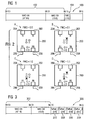
- FIG. 1 is a schematic representation of an entry 100 in a database of a coupling node.
- the coupling node connects two communication networks (not shown here).
- Each database entry of this database is compared with a first part of a predefined information of data to be transmitted.
- the first part of the predefined information is the source address of the data.
- the source address of the data is the address of the network device that sent the data.
- the source address of the data may be, for example, a media access Control (MAC) source address.
- the MAC source address may also be referred to as MAC-SA. This abbreviation stands for MAC source address.
- the database entry 100 comprises 64 bits, with the numbering running from 0 to 63.
- a MAC-SA 102 is stored in bits 16-63 of the database entry 100.
- database entry 100 includes two forward control (FWC) bits 104.
- the FWC bits are bits 14 and 15 of database entry 100. Also, more FWC bits or just one FWC bit may be used.
- the FWC bits form a second part of the predefined information.
- the coupling node reads out the first predefined information from the data.
- the first predefined information is the MAC-SA of the data.
- the coupling node compares this MAC-SA of the data with the entries in the database. If the MAC-SA of the data matches the MAC-SA 102 of an entry in the database, the coupling node reads out the FWC bits 104 of the database entry and forwards the data using the FWC bits.
- FIG. 2 includes four schematic representations of a coupling node 200 and illustrates the routing of data when the second predefined information has been read out. Depending on the read second predefined information, the FWC bits, the data is forwarded differently.
- the coupling node 200 comprises four ports 202, 204, 206, 208.
- the coupling node 200 has read out the FWC bits 0: 0. In this case, the coupling node 200 forwards the data to each of its four ports 202, 204, 206, 208. In this case, the data is re-issued via each port.
- the coupling node 200 may be located, for example, in a first communication network.
- Over port 204 can Data is received from a second automation network. Via port 202 data can be output to the second communication network.
- the ports 206 and 208 are each for receiving and transmitting data from the first and the first communication network.
- Part B of FIG. 2 is a schematic view of a coupling node 200 as in part A.
- the difference to part A is that the FWC bits 0: 1 have been read from the database.
- the FWC bits 0: 1 cause the coupling node 200 to transmit no data over port 202.
- a transmission of the data to the second communication network is prevented.
- Part C is a schematic view of a coupling node 200 as seen from parts A and B.
- the coupling node has read out the FWC bits 1: 0.
- These FWC bits cause the coupling nodes to not output data received over the port 204 from the second network to the first network. This may be the case, for example, for data that should not be transmitted to the first communication network.
- Part D is a schematic representation of a coupling node 200 as in parts A-C, with the difference that the coupling node 200 has read out the FWC bits 1: 1.
- both the data is prevented from being transmitted from the first to the second network and from the second to the first network. Only one transfer from port 206 to port 208 or vice versa is possible. Thus, both the transmission of data from the first to the second network and vice versa is prevented.
- This method may also be referred to as source address dependent routing of the data.
- FIG. 3 Figure 3 is a schematic view of a database entry 300 in a coupling node in a communication system.
- the database entry 300 in contrast to the database entry, comprises the FIG. 1 a destination address (MAC-DA) 302.
- the MAC-DA 300 has the same format as the MAC-SA FIG. 1 ,
- the destination address 302 denotes a data destination.
- the MAC-DA 302 corresponds to the MAC address of a network device.
- the database entry 300 in bits 0 through 15 includes four entries 304, 306, 308, 310 in which a send port is specified for the destination address 302 for each potential receive port of the link node.
- the entries 304-310 may therefore also be referred to as commit bits.
- the database entry 300 thus determines for data with the destination address 302 via which port the data is to be sent out when they are received at a specific port.
- commit bits 304 specify the associated transmit port for receiving the data at a first port
- commit bits 306 specify the transmit port for receiving the data at a second receive port.
- designation bits 308 and 310 for a third and a fourth reception port.
- the commit bits 304-310 may also specify for a receive port that the data is no longer transmitted. In this case, database entry 300 for data destination 302 does not include an associated send port with the corresponding receive port.
- This method can also be referred to as destination-address-dependent forwarding of the data.
- FIG. 4 16 is a schematic view of a communication system 400 having a first communication network 402 and a second communication network 404.
- the first communication network 402 is connected to the second communication network 404 by means of four coupling nodes 408, 410, 412, 414 connected.
- the coupling nodes 408 and 410 form a connection of the first communication network 402 with the second communication network 404 at a first location and the coupling nodes 412 and 414 form the connection of the first communication network 402 with the second communication network 404 at a second location.
- the first and second communication networks 402 and 404 each include a plurality of network devices 406.
- the data is transmitted by a transmitter 416 in the first communication network 402.
- the communication network 402 is shown here in a ring. It should be noted, however, that other network geometries are possible.
- the transmitter 416 transmits the data to both its right and left neighbors in the ring structure.
- Sending the data in two different directions should ensure two redundant transmission paths to the destination of the data.
- the data reaches both the coupling node 410 and the coupling node 412.
- the data is forwarded from the coupling nodes 410 and 412 to the second communication network 404.
- Such forwarding may be based on the destination address of the data.
- the decision as to whether data is forwarded to the second communication network 404 is made on the basis of the predefined information.
- the predefined information consists of a first and a second part.
- the first part is the source address of the data or the destination address of the data.
- the second part of the information is located in the coupling node.
- the second part of the information is read from a database.
- the data After the data has been transferred from the coupling node 412 to the coupling node 414 and from the coupling node 410 to the coupling node 408, the data continues to be transmitted over two redundant transmission paths through the second communication network 404 transferred. A retransmission from the coupling nodes 408 and 414 to the coupling nodes 410 and 412 does not occur due to the predefined information.
- the prevention of the retransmission of the data to the coupling nodes 410 and 412 may be determined by either the destination address or the source address of the data. For example, transmission from the second network 404 to the first network 402 is prevented when the source address in the databases of the coupling nodes 408 and 414 is connected to at least one FWC bit that prevents transmission to the first communication network 402. Alternatively, the transmission may be by designation bits - as in FIG. 3 described - prevented.
- the FWC bits 00 would be stored, for example, for the source address of the data in the coupling node 410, which allows a transmission into the second communication network 404.
- the FWC bits 00 are also stored in the database of the coupling node 412.
- the FWC bits 01 are connected to the source address of the data in the database. This prevents transmission to the first communication network 402.
- the coupling node 410 and the coupling node 412 In the prevention of data transmission by means of the destination address, as in FIG. 3 described, in the coupling node 410 and the coupling node 412, the transmission of the data to the second communication network 404 is allowed. In the coupling nodes 408 and 414, transmission of the data to the first communication network 402 is prevented.
- Such a configuration of the coupling nodes is advantageous in order to prevent a retransmission of the data into the first communication network.
- FIG. 5 is a schematic representation of a communication system 400 having a first communication network 402 and a second communication network 404.
- the communication networks 402 and 404 are similar to those in FIG FIG. 4 built up.
- the transmitter 416 in turn transmits data to two network devices 406 of the first communication network 402.
- data transmission into the second communication network 404 is prevented.
- the prevention can be done for example by FWC bits.
- FWC bits 00 are stored for this purpose in the databases of the coupling nodes 410 and 412, which allow transmission of the data into the second communication network 404.
- the FWC bits 11 are stored, which do not allow a forwarding of the data within the second communication network 404.
- the data from the transmitter 416 are thus transmitted from the coupling node 410 to the coupling node 408 and from the coupling node 412 to the coupling node 414.
- the coupling nodes 408 and 414 do not transfer the data any further, thus avoiding unnecessary traffic in the second communication network 404.
- the prevention of data transmission may be accomplished by comparing the destination address of the data with the database in the coupling nodes 408-414. In order to prevent data transmission from the first communication network 402 to the second communication network 404, it is defined in the received data link nodes 408 and 414 with this destination address in the database that such data is not forwarded via the ports connected to the second communication network 404. Thus, unnecessary data transfers in the second communication network 404 are prevented.
- FIG. 6 is a schematic view of a communication system 600 having a first communication network 402 and a second communication network 602.
- the communication network 602 is garland-shaped, so it does not form a self-contained ring. Again, it should be emphasized that other network geometries are applicable to the first and second communication networks 402 and 602. For ease of illustration, an annular first communication network 402 and a garland-shaped second communication network 602 are shown here.
- the data transmitter 604 which transmits data to its two adjacent network devices 406.
- the data is forwarded via the coupling nodes 606 and 608 to the first communication network.
- a retransmission of the data into the second communication network 602 is prevented by the coupling nodes 606 and 608.
- the prevention can take place, for example, by storing the FWC bits 0: 1 for the source address of the data in the database of the coupling nodes 606 and 608, which makes possible a transmission of the data from the second communication network 602 into the first communication network 402.
- retransmission of the data from the first communication network 402 to the second communication network 602 is prevented by the FWC bits 0: 1.
- the coupling nodes 606 and 608 for the destination address of the data may be set with the setting bits so that these data may not be output through the port connected to the second communication network 602. Thus, a retransmission of the data from the first communication network 402 to the second communication network 602 is prevented.
- FIG. 7 is a schematic view of a communication system having a first communication network 402 and a second communication network 602.
- the two communication networks 402 and 602 are connected via the coupling nodes 606 and 608.
- the first communication network 402 to the second communication network 602 allows. This can be done, for example, by storing the forward control bits 0: 0 for the source address of the transmitter 604 in the coupling nodes 606 and 608 in the database, which allow the data to be transmitted back to the second communication network 602.
- for the destination address of the data may be determined by the determination bits in the database that a retransmission of the data in the second communication network 602 is possible.
- two redundant transmission paths are also created for a garland-shaped communication network such as the second communication network 602.
- FIG. 8 is a schematic view of a communication system 600 having a first communication network 402 and a second communication network 602.
- the data is transmitted by a transmitter 416 in the first communication network 402 in two directions.
- Coupling nodes 408 and 410 connect the first communication network 402 to the second communication network 602.
- the data transmitted by the transmitter 416 reaches the coupling nodes 408 and 410, the data is forwarded to network devices 406 of the second communication network 602. A retransmission of the data from the second communication network 602 to the first communication network 402 is prevented.
- the prevention can be done for example by forward control bits.
- the forward control bits 10 are stored in the databases of the coupling nodes 408 and 410 for the source address of the transmitter 416. These forward control bits prevent the data from being transferred back from the second communication network 602 to the first communication network 402.
- the prevention of the retransmission of the data from the second communication network 602 to the first communication network 402 by the commit bits are not assigned any transmission ports upon receipt via the ports connected to the second communication network 602. Thus, transmission of the data from the second communication network 602 to the first communication network 402 is prevented.
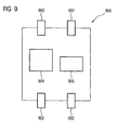
- FIG. 9 Figure 10 is a block diagram of a coupling node 900.
- the coupling node 900 includes a plurality of ports 902. Each port 902 is suitable for receiving and transmitting data.
- the coupling node 900 comprises a digital storage medium 904.
- the database is stored with the second part of the predefined information.
- a program of instructions is stored with the digital storage medium 904. The program may be executed by the processor 906 of the coupling node 900.
- the receiving port is registered when receiving data and the first part of the predefined information is read from the data.
- the first part of the predefined information is compared with the database of the coupling node 900 and the second part of the predefined information is read out.
- the processor 906 is adapted to prevent, upon execution of the program, the retransmission of data originally received from the first communication network and received by the second communication network back into the first communication network.
Landscapes
- Engineering & Computer Science (AREA)
- Computer Networks & Wireless Communication (AREA)
- Signal Processing (AREA)
- Data Exchanges In Wide-Area Networks (AREA)
- Small-Scale Networks (AREA)
Description
Die Erfindung betrifft die redundante Kommunikation in einem Kommunikationssystem, insbesondere die redundante Kommunikation in einem Kommunikationssystem mit mehreren Kommunikationsnetzwerken. Ein Verfahren entsprechend dem Oberbegriff des Patentanspruchs 1 ist aus
In
Ein Netzwerk wird hier insbesondere als ein Zusammenschluss mehrerer Netzwerkgeräte verstanden, die drahtlos oder über Netzwerkkabel miteinander kommunizieren können. Bei einem Kommunikationssystem mit mehreren Kommunikationsnetzwerken sind die Kommunikationsnetzwerke miteinander über sogenannte Kopplungsknoten verbunden. Die Kopplungsknoten dienen dazu, dass Daten von einem ersten Kommunikationsnetzwerk in ein zweites und umgekehrt übertragen werden können. Eine kommunikationsnetzwerkübergreifende Kommunikation ist also in einem solchen Kommunikationssystem möglich.A network is understood here in particular as an association of several network devices that can communicate with each other wirelessly or via network cables. In a communication system having a plurality of communication networks, the communication networks are connected to each other via so-called coupling nodes. The coupling nodes serve to allow data to be transferred from a first communication network to a second and vice versa. A communications network-spanning communication is thus possible in such a communication system.
Eine redundante Kommunikation in einem solchen Kommunikationssystem ist von Vorteil, da so Unterbrechungen des Kommunikationswegs nicht automatisch bedeuten, dass die Kommunikation nicht stattfinden kann. Bei einer Verwendung eines zweiten Kommunikationswegs kann dieser als Alternative zum ersten Kommunikationsweg dienen, falls der erste Kommunikationsweg unterbrochen ist. Diese Art der Kommunikation wird vor allem in Automatisierungsnetzwerken angewandt, wo Automatisierungsdaten, die für einen Produktionsprozess wichtig sind, verwendet werden.A redundant communication in such a communication system is advantageous because interruptions of the communication path do not automatically mean that the communication can not take place. When using a second communication path this can be used as an alternative to the first Communication path, if the first communication is interrupted. This type of communication is mainly used in automation networks, where automation data, which are important for a production process, are used.
Eine solche redundante Kommunikation kann zum Beispiel dadurch erfolgen, dass ein Signal, das von einem ersten Netzwerkgerät eines ersten Kommunikationsnetzwerk zu einem zweiten Netzwerkgerät eines zweiten Kommunikationsnetzwerks übertragen werden soll, an einen Kopplungsknoten, der das erste Kommunikationsnetzwerk mit dem zweiten Kommunikationsnetzwerk verbindet, sowohl an ein Netzwerkgerät des ersten Kommunikationsnetzwerks als auch an einen weiteren Kopplungsknoten im zweiten Kommunikationsnetzwerk ausgegeben wird. Das Signal wird also sowohl im ersten als auch im zweiten Kommunikationsnetzwerk übertragen. Das über das erste Kommunikationsnetzwerk weiter übertragene Signal wird dann an einen weiteren Kopplungsknoten an einen weiteren Kopplungsknoten des zweiten Kommunikationsnetzwerks übertragen. Auf diese Weise entstehen zwei unterschiedliche Netzwerkpfade vom ersten Netzwerkgerät des ersten Netzwerks zum zweiten Netzwerkgerät des zweiten Kommunikationsnetzwerks.Such a redundant communication can take place, for example, in that a signal, which is to be transmitted from a first network device of a first communication network to a second network device of a second communication network, to a coupling node, which connects the first communication network to the second communication network, both to a Network device of the first communication network as well as to another coupling node in second communication network is output. The signal is thus transmitted both in the first and in the second communication network. The signal transmitted further via the first communication network is then transmitted to a further coupling node to a further coupling node of the second communication network. In this way, two different network paths arise from the first network device of the first network to the second network device of the second communication network.
Der Erfindung liegt demgegenüber die Aufgabe zugrunde, ein verbessertes Verfahren zur redundanten Kommunikation in einem Kommunikationssystem zu schaffen. Außerdem liegt der Erfindung die Aufgabe zugrunde, einen verbesserten Kopplungsknoten, ein verbessertes computerlesbares Speichermedium für einen solchen Kopplungsknoten und ein verbessertes Kommunikationssystem mit einem solchen Kopplungsknoten zu schaffen.The invention is the object of the invention to provide an improved method for redundant communication in a communication system. It is another object of the present invention to provide an improved coupling node, an improved computer-readable storage medium for such a coupling node, and an improved communication system having such a coupling node.
Die der Erfindung zugrunde liegenden Aufgaben werden jeweils mit den Merkmalen der unabhängigen Patentansprüche gelöst. Ausführungsformen der Erfindung sind in den abhängigen Patentansprüchen gegeben.The objects underlying the invention are each achieved with the features of the independent claims. Embodiments of the invention are given in the dependent claims.
Erfindungsgemäß wird ein Verfahren zur redundanten Kommunikation in einem Kommunikationssystem geschaffen. Das Kommunikationssystem umfasst dabei mehrere Kommunikationsnetzwerke. Die Kommunikationsnetzwerke sind über zumindest einen Kopplungsknoten miteinander verbunden. Die Kommunikationsnetzwerke umfassen mehrere Netzwerkgeräte.According to the invention, a method for redundant communication in a communication system is provided. The communication system comprises several communication networks. The communication networks are connected to each other via at least one coupling node. The communication networks include multiple network devices.
Innerhalb des Kommunikationssystems werden Daten von einem ersten Netzwerkgerät des ersten Kommunikationsnetzwerks zu einem zweiten Netzwerkgerät des zweiten Kommunikationsnetzwerks über zumindest einen Kopplungsknoten und/oder von dem ersten Netzwerkgerät zu einem dritten Netzwerkgerät des ersten Kommunikationsnetzwerks übertragen. Die Übertragung vom ersten zum zweiten Netzwerkgerät und/oder die Übertragung vom ersten zum dritten Netzwerkgerät erfolgt über zumindest zwei redundante Übertragungswege. Zwei redundante Übertragungswege bedeuten hier, dass innerhalb des Kommunikationsnetzwerks zwei unterschiedliche Wege vom ersten zum zweiten und/oder vom ersten zum dritten Netzwerkgerät für die Übertragung der Daten benutzt werden. Falls einer der beiden Übertragungswege fehlerhaft oder unterbrochen sein sollte, erreichen die Daten ihr Ziel über den jeweils anderen Übertragungsweg.Within the communication system, data is transmitted from a first network device of the first communication network to a second network device of the second communication network via at least one coupling node and / or from the first network device to a third network device of the first communication network. The transmission from the first to the second network device and / or the transmission from first to third network device via at least two redundant transmission paths. Two redundant transmission paths mean here that two different paths from the first to the second and / or from the first to the third network device for the transmission of the data are used within the communication network. If one of the two transmission paths should be faulty or interrupted, the data reaches its destination via the other transmission path.
Aufgrund einer vor der Übertragung vordefinierten Information wird eine Rückübertragung der Daten vom zweiten zum ersten Kommunikationsnetzwerk bei einer Übertragung vom ersten zum zweiten Netzwerkgerät verhindert. Die vordefinierte Information besteht aus einem ersten Teil und einem zweiten Teil. Die Daten umfassen den ersten Teil der vordefinierten Information und der Kopplungsknoten umfasst den zweiten Teil der vordefinierten Information.Due to an information predefined before the transmission, a retransmission of the data from the second to the first communication network during a transmission from the first to the second network device is prevented. The predefined information consists of a first part and a second part. The data comprises the first part of the predefined information and the coupling node comprises the second part of the predefined information.
Eine solche Verhinderung der Rückübertragung der Daten vom zweiten zum ersten Kommunikationsnetzwerk ist vorteilhaft, da so vermieden wird, dass Daten unnötigerweise wieder zurück in das erste Kommunikationsnetzwerk übertragen werden. Da das Ziel der Daten im zweiten Kommunikationsnetzwerk liegt, ist es vorteilhaft, eine Rückübertragung der Daten in das erste Kommunikationsnetzwerk zu verhindern. So wird vermieden, dass Daten im ersten Netzwerk kreisen, ohne dass dies einen redundanten Übertragungsweg zum zweiten Netzwerkgerät bildet. Die Verhinderung ist also vorteilhaft, um unnötigen Datenverkehr im ersten Netzwerk zu verhindern.Such a prevention of the retransmission of the data from the second to the first communication network is advantageous because it avoids the unnecessary transfer of data back into the first communication network. Since the destination of the data lies in the second communication network, it is advantageous to prevent a retransmission of the data into the first communication network. This avoids that data in the first network circling, without this forms a redundant transmission path to the second network device. The prevention is thus advantageous to prevent unnecessary traffic in the first network.
Durch Verhinderung der Rückübertragung wird außerdem der maximal mögliche Laufzeitunterschied zwischen einem Frame der Daten und seinem Duplikat, das über den zweiten redundanten Übertragungsweg übertragen wurde, verringert. Solche Duplikate, die zweimal an einem Kopplungsknoten oder an einem Netzwerkgerät registriert wurden, werden mit einer Duplikatefilter-Liste gefiltert. Durch die Verringerung des maximal möglichen Laufzeitunterschieds können Duplikate mit einer kleineren Duplikatefilter-Liste zuverlässig gefiltert werden.Preventing retransmission also reduces the maximum possible skew between a frame of data and its duplicate transmitted over the second redundant transmission path. Such duplicates, which have been registered twice at a coupling node or at a network device, are filtered with a duplicate filter list. By reducing the maximum possible Maturity differences can reliably filter duplicates with a smaller duplicate filter list.
Besonders vorteilhaft ist dies bei Automatisierungsystemen, die mehrere Automatisierungsnetzwerke umfassen.This is particularly advantageous in automation systems that include multiple automation networks.
Ein Automatisierungsnetzwerk kann z.B. als industrielles Automatisierungsnetzwerk ausgebildet sein. Solche industriellen Automatisierungsnetzwerke können z.B. zur Steuerung und/oder Regelung von industriellen Anlagen (z.B. Produktionsanlagen, Förderanlagen usw.), Maschinen und/oder Geräten ausgebildet, eingerichtet und/oder vorgesehen sein. Insbesondere können Automatisierungsnetzwerke bzw. industrielle Automatisierungsnetzwerke Echzeit-Kommunikationsprotokolle (z.B. Profinet, Profibus, Real-Time-Ethernet)zur Kommunikation zumindest zwischen den an den Steuerungs- und/oder Regelungsaufgaben beteiligten Komponenten (z.B. zwischen den Steuerungseinheiten und den zu steuernden Anlagen und/oder Maschinen) aufweisen. Die sichere Übertragung von Daten über Speichermedien ist ebenfalls abgedeckt.An automation network may e.g. be designed as an industrial automation network. Such industrial automation networks may e.g. for the control and / or regulation of industrial installations (for example production plants, conveyor systems, etc.), machines and / or devices, which are designed and / or provided. In particular, automation networks or industrial automation networks real-time communication protocols (eg Profinet, Profibus, Real-Time Ethernet) for communication at least between the components involved in the control and / or regulatory tasks (eg between the control units and the systems to be controlled and / or Machines). The secure transmission of data via storage media is also covered.
Weiterhin kann neben einem Echtzeit-Kommunikationsprotokoll aber auch noch mindestens ein weiteres Kommunikationsprotokoll (das z.B. nicht echtzeitfähig zu sein braucht) in dem Automatisierungsnetzwerk bzw. industriellen Automatisierungsnetzwerk vorgesehen sein, z.B. zum Überwachen, Einrichten, Umprogrammieren oder/oder Umparametrieren einer oder mehrerer Steuerungseinheiten im Automatisierungsnetzwerk.Furthermore, in addition to a real-time communication protocol, at least one further communication protocol (which, for example, need not be real-time capable) may also be provided in the automation network or industrial automation network, e.g. for monitoring, setting up, reprogramming or / or reparameterizing one or more control units in the automation network.
Ein Automatisierungsnetzwerk kann z.B. drahtgebundene Kommunikationskomponenten und/oder drahtlose Kommunikationskomponenten umfassen. Außerdem kann ein Automatisierungsnetzwerk zumindest eine Automatisierungseinrichtung umfassen.An automation network may e.g. Wired communication components and / or wireless communication components include. In addition, an automation network may include at least one automation device.
Eine Automatisierungseinrichtung kann beispielsweise ein Computer, PC und/oder Controller mit Steuerungs-Aufgaben bzw. Steuerungs-Fähigkeiten sein. Insbesondere kann eine Automatisierungseinrichtung beispielsweise eine industrielle Automatisierungseinrichtung sein, die z.B. speziell zur Steuerung und/oder Regelung industrieller Anlagen ausgebildet, eingerichtet und/oder vorgesehen sein kann. Insbesondere können solche Automatisierungseinrichtungen bzw. industriellen Automatisierungseinrichtungen echtzeitfähig sein, d.h. eine Steuerung bzw. Regelung in Echtzeit ermöglichen. Dazu kann die Automatisierungseinrichtung bzw. die industrielle Automatisierungseinrichtung z.B. ein Echtzeitbetriebssystem umfassen und/oder zumindest unter anderem ein echtzeitfähiges Kommunikationsprotokoll zur Kommunikation (z.B. Profinet, Profibus, Real-Time-Ethernet) unterstützen.An automation device can be, for example, a computer, PC and / or controller with control tasks or control capabilities. In particular, an automation device For example, be an industrial automation device, for example, designed, equipped and / or provided specifically for controlling and / or regulating industrial plants. In particular, such automation devices or industrial automation devices can be real-time capable, ie enable real-time control or regulation. For this purpose, the automation device or the industrial automation device, for example, comprise a real-time operating system and / or at least support, inter alia, a real-time communication protocol for communication (eg Profinet, Profibus, Real-Time Ethernet).
Ein Automatisierungsnetzwerk umfasst mehrere Sensoren und Aktuatoren. Die Aktuatoren und Sensoren werden von zumindest einer Steuerungseinrichtung gesteuert. Die Aktuatoren, die Sensoren und die zumindest eine Steuerungseinrichtung tauschen Daten miteinander aus. Zum Datenaustausch wird ein Automatisierungsprotokoll verwendet. Die zumindest eine Steuerungseinrichtung steuert die Aktuatoren, die Sensoren und den Datenaustausch so, dass ein maschineller Fertigungsprozess abläuft, in dem z.B. ein Produkt hergestellt wird.An automation network includes multiple sensors and actuators. The actuators and sensors are controlled by at least one control device. The actuators, the sensors and the at least one control device exchange data with each other. An automation protocol is used for data exchange. The at least one controller controls the actuators, the sensors and the data exchange so that a machining process takes place in which e.g. a product is produced.
Eine industrielle Automatisierungseinrichtung kann z.B. eine speicherprogrammierbare Steuerung, ein Modul oder Teil einer speicherprogrammierbaren Steuerung, eine in einem Computer oder PC integrierte speicherprogrammierbare Steuerung sowie entsprechende Feldgeräte, Sensoren und/oder Aktoren, Ein-und/oder Ausgabegeräte oder Ähnliches zum Anschluss an einer speicherprogrammierbare Steuerung sein oder solche umfassen.An industrial automation device may e.g. a programmable logic controller, a module or part of a programmable logic controller, be integrated in a computer or PC programmable logic controller and corresponding field devices, sensors and / or actuators, input and / or output devices or the like for connection to a programmable logic controller or include such.
Als Automatisierungsprotokoll im Sinne der vorliegenden Erfindung wird jede Art von Protokoll verstanden, das zur Kommunikation mit Automatisierungs-Einrichtungen gemäß der vorliegenden Beschreibung vorgesehen, geeignet und/oder eingerichtet ist. Solche Automatisierungsprotokolle können beispielsweise das Profi-Bus-Protokoll (z. B. gemäß IEC 61158/EN50170), ein Profi-Bus-DP-Protokoll, ein Profi-Bus-PA-Protokoll, ein Profi-Net-Protokoll, ein Profi-Net-I0-Protokoll, ein Protokoll gemäß AS-Interface, ein Protokoll gemäß IO-Link, ein KNX-Protokoll, ein Protokoll gemäß einer Mehrpunkt-Schnittstelle (Multipoint-Interface, MPI), ein Protokoll für eine Punkt-zu-Punkt-Kopplung (Point-to-Point, PtP), ein Protokoll gemäß den Spezifikationen der S7-Kommunikation (welches beispielsweise zur Kommunikation von speicherprogrammierbaren Steuerungen der Firma Siemens vorgesehen und eingerichtet ist) oder auch ein Industrial-Ethernet-Protokoll oder Real-Time-Ethernt-Protokoll bzw. weitere spezifische Protokolle für die Kommunikation mit Automatisierungsgeräten sein. Als Automatisierungsprotokoll im Sinne der vorliegenden Beschreibung können auch beliebige Kombinationen der vorgenannten Protokolle vorgesehen sein.As an automation protocol in the context of the present invention, any type of protocol is provided, which is provided for communication with automation devices according to the present description, suitable and / or set up. Such automation protocols can be, for example, the professional bus protocol (eg according to IEC 61158 / EN50170), a Profi-Bus-DP protocol, a Profi-Bus-PA protocol, a Profi-Net protocol, a Profi-Net-I0 protocol, a protocol according to AS-Interface, a protocol according to IO Link, a KNX protocol, a multipoint interface (MPI) protocol, a point-to-point (PtP) protocol, a protocol according to the specifications of S7 communication (which is provided and set up, for example, for the communication of programmable logic controllers from Siemens) or an industrial Ethernet protocol or real-time Ethernt protocol or other specific protocols for communication with automation devices. As an automation protocol in the sense of the present description, any combination of the aforementioned protocols may be provided.
Nach Ausführungsformen der Erfindung wird der erste Teil der vordefinierten Information von dem zumindest einem Kopplungsknoten gelesen. Der Kopplungsknoten kennt dann also beide Teile der vordefinierten Information. Der erste Teil wurde vom Kopplungsknoten aus den Daten ausgelesen und der zweite Teil befindet sich im Kopplungsknoten, zum Beispiel auf einem digitalen Speichermedium, und kann vom Kopplungsknoten ebenfalls ausgelesen werden.According to embodiments of the invention, the first part of the predefined information is read by the at least one coupling node. The coupling node then knows both parts of the predefined information. The first part was read out of the data by the coupling node and the second part is located in the coupling node, for example on a digital storage medium, and can also be read by the coupling node.
Der erste Teil der vordefinierten Information ist nach Ausführungsformen der Erfindung eine Quelladresse der Daten. Die Quelladresse der Daten ist die Adresse des Netzwerkgeräts, das die Daten ausgesendet hat. Dies kann beispielsweise eine Medium Access Control (MAC) Adresse sein. Die Quelladresse identifiziert eindeutig das Netzwerkgerät.The first part of the predefined information according to embodiments of the invention is a source address of the data. The source address of the data is the address of the network device that sent the data. This can be for example a medium access control (MAC) address. The source address uniquely identifies the network device.
In diesem Fall befindet sich der zweite Teil der vordefinierten Information in einer Datenbank des Kopplungsknotens. Jeder Eintrag der Datenbank umfasst eine Netzwerkgeräteadresse und zumindest ein Forward Control (FWC) Bit. Mit dem zumindest einen FWC-Bit ist einstellbar, dass Daten zum Beispiel nur vom ersten zum zweiten Netzwerk, aber nicht vom zweiten zum ersten Netzwerk gesendet werden dürfen. Mit dem zumindest einen FWC-Bit wird festgelegt, über welche Ports der Kopplungsknoten die empfangenen Daten weiterleitet.In this case, the second part of the predefined information is in a database of the coupling node. Each entry of the database includes a network device address and at least one forward control (FWC) bit. With the at least one FWC bit is adjustable that data for example only from the first to the second network, but not from the second to the first network may be sent. The at least one FWC bit determines via which ports the coupling node forwards the received data.
Wenn Daten mit einer bestimmten Quelladresse von dem Kopplungsknoten empfangen werden, ermittelt der Kopplungsknoten in der Datenbank durch Vergleichen der Quelladresse mit den Datenbankeinträgen die zweite vordefinierte Information. Die zweite vordefinierte Information kann zum Beispiel das zumindest eine FWC-Bit sein, das festlegt, ob die empfangenen Daten an das erste und/oder an das zweite Netzwerk weitergeleitet werden.When data having a particular source address is received by the coupling node, the coupling node in the database determines the second predefined information by comparing the source address with the database entries. The second predefined information may be, for example, the at least one FWC bit that determines whether the received data is forwarded to the first and / or second network.
Nach Ausführungsformen der Erfindung umfasst der Kopplungsknoten mehrere Ports. Über jeden der Ports können Daten empfangen und gesendet werden. Der zweite Teil der vordefinierten Information befindet sich in einer Datenbank. Die Datenbank umfasst mehrere Einträge.According to embodiments of the invention, the coupling node comprises a plurality of ports. Data can be received and sent via each of the ports. The second part of the predefined information is in a database. The database contains several entries.
Zunächst werden Daten an einem ersten Port empfangen. Aus diesen Daten wird der erste Teil der vordefinierten Information ausgelesen. Der zweite Teil der vordefinierten Information wird durch Vergleich der Datenbankeinträge mit dem ersten Teil der vordefinierten Information ermittelt. Aus dem zweiten Teil der vordefinierten Information wird zumindest ein zweiter Port zur Weiterleitung der Daten ermittelt, falls der zweite Teil der vordefinierten Information zumindest einen zweiten Port umfasst. Die Daten werden dann über den zumindest einen zweiten Port weitergeleitet, falls der zweite Teil der vorliegenden Information zumindest einen zweiten Port umfasst. Falls der zweite Teil der vordefinierten Information keinen zweiten Port umfasst, wird eine Weiterleitung der Daten verhindert.First, data is received at a first port. From this data, the first part of the predefined information is read out. The second part of the predefined information is determined by comparing the database entries with the first part of the predefined information. At least one second port for forwarding the data is determined from the second part of the predefined information if the second part of the predefined information comprises at least one second port. The data is then forwarded via the at least one second port if the second part of the present information comprises at least one second port. If the second part of the predefined information does not include a second port, forwarding of the data is prevented.
Der Kopplungsknoten ermittelt also den zweiten Teil der vordefinierten Information mit Hilfe des ersten Teils der vordefinierten Information. Der zweite Teil der vordefinierten Information gibt an, ob und wenn ja, wie viele und welche Ports zur Weiterleitung der Daten verwendet werden sollen. Somit lässt sich durch den ersten und ersten zweiten Teil der vordefinierten Information die Weiterleitungsrichtung der Daten festlegen. Beispielsweise könnte der erste Teil und der zweite Teil der vordefinierten Information festlegen, dass die Daten nur über den Port weitergeleitet werden, der mit dem ersten Netzwerk verbunden ist. So wird eine Übertragung der Daten in das zweite Netzwerk verhindert. Das gleiche Verfahren kann auch angewandt werden, um eine Übertragung der Daten vom zweiten zum ersten Kommunikationsnetzwerk zu verhindern.The coupling node thus determines the second part of the predefined information with the aid of the first part of the predefined information Information. The second part of the predefined information indicates whether and if so, how many and which ports should be used to forward the data. Thus, the forwarding direction of the data can be defined by the first and first second part of the predefined information. For example, the first part and the second part of the predefined information may specify that the data is forwarded only over the port that is connected to the first network. This prevents transmission of data to the second network. The same method can also be used to prevent transmission of data from the second to the first communication network.
Nach Ausführungsformen der Erfindung umfasst der Kopplungsknoten mehrere Ports. Über jeden der Ports können Daten empfangen und gesendet werden. Der zweite Teil der vordefinierten Information besteht aus einer Datenbank. Die Datenbank umfasst mehrere Einträge, wobei jeder Eintrag für jeden der Ports keinen oder zumindest einen dazugehörigen Sendeport umfasst.According to embodiments of the invention, the coupling node comprises a plurality of ports. Data can be received and sent via each of the ports. The second part of the predefined information consists of a database. The database comprises a plurality of entries, each entry for each of the ports comprising no or at least one associated send port.
Der erste Teil der vordefinierten Information umfasst ein Datenziel. Dies kann beispielsweise eine Multicast- oder Unicast-Adresse der Daten sein. Der erste Teil der vordefinierten Information legt also das Netzwerkgerät fest, zu dem die Daten übermittelt werden sollen.The first part of the predefined information comprises a data destination. This can be, for example, a multicast or unicast address of the data. The first part of the predefined information thus defines the network device to which the data is to be transmitted.
Am Kopplungsknoten werden die Daten zunächst an einem ersten Port empfangen. Der Kopplungsknoten liest dann das Datenziel aus und registriert den ersten Port als Empfangsport. In der Datenbank wird dann nach dem Datenbankeintrag gesucht, der mit dem Datenziel und dem ersten Port übereinstimmt. Jeder Datenbankeintrag umfasst außerdem keinen oder zumindest einen Sendeport. Der jeweilige Sendeport wird also durch den ersten Port und das Datenziel bestimmt. Es ist auch möglich, dass für einen ersten Port und ein bestimmtes Datenziel kein Sendeport definiert ist. In diesem Fall werden die Daten nicht weitergeleitet.At the coupling node, the data is first received at a first port. The coupling node then reads the data destination and registers the first port as a receive port. The database is then searched for the database entry that matches the data destination and the first port. Each database entry also includes no or at least one send port. The respective send port is thus determined by the first port and the data destination. It is also possible that for a first port and a certain data destination no send port is defined. In this case, the data will not be forwarded.
Aus der Datenbank wird der zumindest eine, zu dem ersten Port zugehörige Sendeport ausgelesen, falls der Datenbankeintrag zumindest einen Sendeport umfasst. Die Daten werden über den zumindest einen ausgelesenen Sendeport weitergeleitet, falls der Datenbankeintrag zumindest einen Sendeport umfasst. Falls der Datenbankeintrag keinen Sendeport umfasst, wird eine Weiterleitung der Daten verhindert.From the database, the at least one send port associated with the first port is read out if the database entry comprises at least one send port. The data is forwarded via the at least one read out transmission port if the database entry comprises at least one transmission port. If the database entry does not include a send port, the data is prevented from being forwarded.
Mit anderen Worten ermittelt der Kopplungsknoten aus dem Datenziel und dem Empfangsport, ob und über welchen oder welche Ports die Daten weitergeleitet werden sollen.In other words, the coupling node determines from the data destination and the reception port whether and via which or which ports the data should be forwarded.
Nach Ausführungsformen der Erfindung ist jeder Datenbankeintrag und das Datenziel durch eine Multicast-Adresse oder eine Unicast-Adresse charakterisiert.According to embodiments of the invention, each database entry and the data destination is characterized by a multicast address or a unicast address.
Nach Ausführungsformen der Erfindung ist das Kommunikationssystem ein Automatisierungssystem. Die Daten sind in diesem Fall Automatisierungsdaten. Ein solches Automatisierungssystem ist besonders vorteilhaft, da unnötige Datenübertragungen im ersten Netzwerk verhindert werden. Somit werden eventuelle Verzögerungen bei Übertragung von anderen Daten im ersten Kommunikationsnetzwerk verhindert. Somit wird ein reibungsloser Produktionsprozess mit Hilfe des Automatisierungssystems gewährleistet.According to embodiments of the invention, the communication system is an automation system. The data in this case is automation data. Such an automation system is particularly advantageous because unnecessary data transfers in the first network are prevented. Thus, possible delays in transmission of other data in the first communication network are prevented. This ensures a smooth production process with the aid of the automation system.
In einem weiteren Aspekt betrifft die Erfindung einen Kopplungsknoten mit mehreren Ports. Die Ports sind dazu ausgebildet, zumindest ein erstes Kommunikationsnetzwerk eines Kommunikationssystems mit einem zweiten Kommunikationsnetzwerk des Kommunikationssystems zu verbinden. Jeder Port ist an ein Kommunikationsnetzwerk angeschlossen. Beispielsweise können zwei Ports des Kopplungsknotens an ein erstes Kommunikationsnetzwerk und zwei Ports des Kopplungsknotens an ein zweites Kommunikationsnetzwerk angeschlossen sein. Somit kann der Kopplungsknoten Daten innerhalb des ersten Kommunikationsnetzwerks oder innerhalb des zweiten Kommunikationsnetzwerks weiterleiten. Auch eine Weiterleitung von Daten vom ersten Kommunikationsnetzwerk zum zweiten Kommunikationsnetzwerk und umgekehrt kann erfolgen.In a further aspect, the invention relates to a coupling node with multiple ports. The ports are configured to connect at least a first communication network of a communication system to a second communication network of the communication system. Each port is connected to a communication network. For example, two ports of the coupling node to a first communication network and two ports of the coupling node to a second Be connected communication network. Thus, the coupling node may forward data within the first communication network or within the second communication network. A forwarding of data from the first communication network to the second communication network and vice versa can take place.
Über die Ports können Daten aus dem ersten und dem zweiten Kommunikationsnetzwerk empfangen und an das erste und das zweite Kommunikationsnetzwerk ausgesendet werden. Der Kopplungsknoten umfasst Mittel zum Auslesen eines ersten Teils einer vordefinierten Information aus den Daten. Der Kopplungsknoten umfasst ferner Speichermittel und Auslesemittel zum Speichern und Auslesen eines zweiten Teils der vordefinierten Information. Vorzugsweise wird der zweite Teil der vordefinierten Information auf einem digitalen Speichermedium in dem Kopplungsknoten gespeichert.Data can be received from the first and the second communication network via the ports and sent out to the first and the second communication network. The coupling node comprises means for reading out a first part of predefined information from the data. The coupling node further comprises memory means and read-out means for storing and reading a second part of the predefined information. Preferably, the second part of the predefined information is stored on a digital storage medium in the coupling node.
Außerdem umfasst der Kopplungsknoten Verhinderungsmittel. Die Verhinderungsmittel sind dazu ausgebildet, in Abhängigkeit von der vordefinierten Information eine Übertragung von empfangenen Daten, die ursprünglich aus dem ersten Kommunikationsnetzwerk stammen und am Kopplungsknoten vom zweiten Kommunikationsnetzwerk empfangen wurden, zurück in das erste Kommunikationsnetzwerk zu verhindern.In addition, the coupling node comprises prevention means. The preventing means are adapted to prevent transmission of received data originally originating in the first communication network and received at the coupling node from the second communication network back into the first communication network, depending on the predefined information.
In noch einem weiteren Aspekt betrifft die Erfindung ein Computer lesbares Speichermedium mit Instruktionen, die bei Ausführung in einem Kopplungsknoten nach Ausführungsformen der Erfindung in einem Kommunikationssystem den Kopplungsknoten zur Ausführung des folgenden Verfahrens veranlassen.In still another aspect, the invention relates to a computer readable storage medium having instructions that when executed in a coupling node according to embodiments of the invention in a communication system cause the coupling node to perform the following method.
Zunächst werden Daten über einen ersten Port empfangen. Der erste Port wird als Empfangsport registriert. Ein erster Teil einer vordefinierten Information wird aus den empfangenen Daten ausgelesen. Ein zweiter Teil der vordefinierten Information wird aus den Speichermitteln des Kopplungsknotens ausgelesen. Eine Übertragung der empfangenen Daten, die ursprünglich aus dem ersten Kommunikationsnetzwerk stammen und am Kopplungsknoten vom zweiten Kommunikationsnetzwerk empfangen wurden, zurück in das erste Kommunikationsnetzwerk wird aufgrund der vordefinierten Information verhindert.First, data is received via a first port. The first port is registered as a receive port. A first part of a predefined information is read from the received data. A second part of the predefined information is read from the storage means of the coupling node. A transmission of the received data originally originating from the first communication network and received at the coupling node by the second communication network back into the first communication network is prevented on the basis of the predefined information.
In noch einem weiteren Aspekt betrifft die Erfindung ein Kommunikationssystem mit zumindest einem Kopplungsknoten nach Ausführungsformen der Erfindung. Das Kommunikationssystem umfasst zumindest ein erstes und ein zweites Kommunikationsnetzwerk. Der zumindest eine Kopplungsknoten umfasst mehrere Ports, wobei der Kopplungsknoten über die Ports zumindest das erste Kommunikationsnetzwerk mit dem zweiten Kommunikationsnetzwerk des Kommunikationssystems verbindet.In yet another aspect, the invention relates to a communication system having at least one coupling node according to embodiments of the invention. The communication system comprises at least a first and a second communication network. The at least one coupling node comprises a plurality of ports, wherein the coupling node connects via the ports at least the first communication network with the second communication network of the communication system.
Im Weiteren werden Ausführungsformen der Erfindung mit Bezugnahme auf die Zeichnungen näher erläutert. Es zeigen:
Figur 1- eine schematische Darstellung eines Eintrags in einer Datenbank des Kopplungsknotens mit FWC-Bits;
Figur 2- eine schematische Darstellung eines Kopplungsknotens mit vier Ports, über die Daten empfangen und gesendet werden können, wobei die Weiterleitung von Daten an bestimmte Ports durch bestimmte Forward-Controlling-Bits verhindert wird;
Figur 3- eine schematische Darstellung eines Eintrags in einer Datenbank im Kopplungsknoten, bei dem einem ersten Port ein zu dem ersten Port zugehöriger Empfangsport zugeordnet wird;
- Figur 4
- eine schematische Darstellung eines Kommunikations-systems mit zwei Kommunikationsnetzwerken, die über Kopplungsknoten miteinander verbunden sind, wobei die Datenübertragung vom zweiten zum ersten Netzwerk verhindert wird.
- Figur 5
- eine schematische Darstellung eines Kommunikations-systems mit zwei Kommunikationsnetzwerken, die über Kopplungsknoten miteinander verbunden sind, wobei die Datenübermittlung vom ersten zum zweiten Netzwerk verhindert wird;
- Figur 6
- ein Kommunikationssystem mit zwei Kommunikations-netzwerken, die über Kopplungsknoten miteinander verbunden sind, wobei ein Kommunikationsnetzwerk girlandenförmig aufgebaut und ein Kommunikations-netzwerk ringförmig aufgebaut ist;
- Figur 7
- ein Kommunikationssystem mit zwei Kommunikations-netzwerken mit redundanter Kommunikation eines Senders in dem girlandenförmigen Netzwerk;
- Figur 8
- eine schematische Darstellung eines Kommunikations-systems mit zwei Kommunikationsnetzwerken mit einem Datensender im ringförmigen Netzwerk und einer redundanten Kommunikation; und
- Figur 9
- ein Blockdiagramm eines Kopplungsknotens.
- FIG. 1
- a schematic representation of an entry in a database of the coupling node with FWC bits;
- FIG. 2
- a schematic representation of a coupling node with four ports over which data can be received and sent, the forwarding of data to certain ports is prevented by certain forward controlling bits;
- FIG. 3
- a schematic representation of an entry in a database in the coupling node, in which a first port associated with the first port receiving port is assigned;
- FIG. 4
- a schematic representation of a communication system with two communication networks, which are interconnected via coupling nodes, the data transmission from the second to the first network is prevented.
- FIG. 5
- a schematic representation of a communication system with two communication networks, which are interconnected via coupling nodes, wherein the data transmission is prevented from the first to the second network;
- FIG. 6
- a communication system having two communication networks connected to each other via coupling nodes, wherein a communication network is garland-shaped and a communication network is ring-shaped;
- FIG. 7
- a communication system having two communication networks with redundant communication of a transmitter in the garland-shaped network;
- FIG. 8
- a schematic representation of a communication system with two communication networks with a data transmitter in the annular network and a redundant communication; and
- FIG. 9
- a block diagram of a coupling node.
Elemente der nachfolgenden Figuren, die einander entsprechen, sind mit denselben Bezugszeichen gekennzeichnet.Elements of the following figures that correspond to each other are identified by the same reference numerals.
Wenn nun am Kopplungsknoten Daten empfangen werden, liest der Kopplungsknoten die erste vordefinierte Information aus den Daten aus. Die erste vordefinierte Information ist die MAC-SA der Daten. Dann vergleicht der Kopplungsknoten diese MAC-SA der Daten mit den Einträgen in der Datenbank. Falls die MAC-SA der Daten mit der MAC-SA 102 eines Eintrags in der Datenbank übereinstimmen, liest der Kopplungsknoten die FWC-Bits 104 des Datenbankeintrags aus und leitet die Daten mit Hilfe der FWC-Bits weiter.Now, when data is received at the coupling node, the coupling node reads out the first predefined information from the data. The first predefined information is the MAC-SA of the data. Then, the coupling node compares this MAC-SA of the data with the entries in the database. If the MAC-SA of the data matches the MAC-
In Teil A von
Der Kopplungsknoten 200 kann sich beispielsweise in einem ersten Kommunikationsnetzwerk befinden. Über Port 204 können Daten aus einem zweiten Automatisierungsnetzwerk empfangen werden. Über Port 202 können Daten an das zweite Kommunikationsnetzwerk ausgegeben werden. Die Ports 206 und 208 dienen jeweils zum Empfang und zum Übertragen von Daten aus dem ersten und zum ersten Kommunikationsnetzwerk.The
Teil B von
Teil C ist eine schematische Ansicht eines Kopplungsknotens 200 wie aus den Teilen A und B. Hier nun hat der Kopplungsknoten die FWC-Bits 1:0 ausgelesen. Diese FWC-Bits veranlassen den Kopplungsknoten dazu, dass Daten, die über den Port 204 vom zweiten Netzwerk empfangen wurden, nicht an das erste Netzwerk ausgegeben werden. Dies kann zum Beispiel für solche Daten der Fall sein, die nicht an das erste Kommunikationsnetzwerk übertragen werden sollen.Part C is a schematic view of a
Teil D ist eine schematische Darstellung eines Kopplungsknotens 200 wie in den Teilen A-C, mit dem Unterschied, dass der Kopplungsknoten 200 die FWC-Bits 1:1 ausgelesen hat. In einem solchen Fall wird sowohl verhindert, dass die Daten vom ersten in das zweite Netzwerk als auch vom zweiten in das erste Netzwerk übertragen werden. Es ist nur eine Übertragung vom Port 206 zum Port 208 oder andersrum möglich. Es wird also sowohl die Übertragung von Daten von dem ersten in das zweite Netzwerk als auch umgekehrt verhindert.Part D is a schematic representation of a
Dieses Verfahren kann auch als quelladressabhängiges Weiterleiten der Daten bezeichnet werden.This method may also be referred to as source address dependent routing of the data.
Der Datenbankeintrag 300 legt also für Daten mit der Zieladresse 302 fest, über welchen Port die Daten ausgesendet werden sollen, wenn sie an einem bestimmten Port empfangen werden. Festlegungsbits 304 legen beispielsweise für einen Empfang der Daten an einem ersten Port den dazugehörigen Sendeport fest, während Festlegungsbits 306 den Sendeport für den Empfang der Daten an einem zweiten Empfangsport festlegen. Entsprechendes gilt für Festlegungsbits 308 und 310 für einen dritten und einen vierten Empfangsport. Es wird also für jeden potenziellen Empfangsport einer oder mehrere Sendeports festgelegt. Die Festlegungsbits 304 - 310 können ebenfalls für einen Empfangsport festlegen, dass die Daten nicht weiter übertragen werden. In diesem Falle umfasst der Datenbankeintrag 300 für das Datenziel 302 mit dem entsprechenden Empfangsport keinen dazugehörigen Sendeport.The
Dieses Verfahren kann auch als zieladressabhängige Weiterleitung der Daten bezeichnet werden.This method can also be referred to as destination-address-dependent forwarding of the data.
Die Daten werden von einem Sender 416 im ersten Kommunikationsnetzwerk 402 ausgesendet. Das Kommunikationsnetzwerk 402 ist hier ringförmig dargestellt. Es ist aber zu beachten, dass auch andere Netzwerkgeometrien möglich sind. In der ringförmigen Struktur des ersten Kommunikationsnetzwerks 402 überträgt der Sender 416 die Daten sowohl an seinen rechten und linken Nachbarn in der Ringstruktur.The data is transmitted by a
Das Aussenden der Daten in zwei verschiedene Richtungen soll zwei redundante Übertragungswege zum Ziel der Daten sicherstellen. Die Daten erreichen sowohl den Kopplungsknoten 410 als auch den Kopplungsknoten 412. Aufgrund der Quelladresse des Senders werden die Daten von den Kopplungsknoten 410 und 412 an das zweite Kommunikationsnetzwerk 404 weitergeleitet. Alternativ kann eine solche Weiterleitung aufgrund der Zieladresse der Daten erfolgen. Die Entscheidung, ob Daten an das zweite Kommunikationsnetzwerk 404 weitergeleitet werden, wird aufgrund der vordefinierten Information getroffen. Die vordefinierte Information besteht aus einem ersten und einem zweiten Teil. Der erste Teil ist die Quelladresse der Daten oder die Zieladresse der Daten. Der zweite Teil der Information befindet sich im Kopplungsknoten. Der zweite Teil der Information wird aus einer Datenbank ausgelesen.Sending the data in two different directions should ensure two redundant transmission paths to the destination of the data. The data reaches both the
Nachdem die Daten vom Kopplungsknoten 412 zum Kopplungsknoten 414 und vom Kopplungsknoten 410 zum Kopplungsknoten 408 übertragen wurden, werden die Daten weiterhin über zwei redundante Übertragungswege durch das zweite Kommunikationsnetzwerk 404 übertragen. Eine Rückübertragung von den Kopplungsknoten 408 und 414 zu den Kopplungsknoten 410 und 412 findet aufgrund der vordefinierten Information nicht statt.After the data has been transferred from the
Die Verhinderung der Rückübertragung der Daten zu den Kopplungsknoten 410 und 412 kann entweder durch die Zieladresse oder die Quelladresse der Daten festgelegt sein. Beispielsweise wird eine Übertragung vom zweiten Netzwerk 404 zum ersten Netzwerk 402 verhindert, wenn die Quelladresse in den Datenbanken der Kopplungsknoten 408 und 414 mit zumindest einem FWC-Bit verbunden ist, das eine Übertragung zum ersten Kommunikationsnetzwerk 402 verhindert. Alternativ kann die Übertragung durch Festlegungsbits - wie in
Bei einer Verhinderung der Übertragung durch die FWC-Bits wären beispielsweise für die Quelladresse der Daten im Kopplungsknoten 410 die FWC-Bits 00 hinterlegt, was eine Übertragung in das zweite Kommunikationsnetzwerk 404 erlaubt. In der Datenbank des Kopplungsknotens 412 sind ebenfalls die FWC-Bits 00 hinterlegt. In den Kopplungsknoten 408 und 414 des zweiten Kommunikationsnetzwerks 404 sind die FWC-Bits 01 mit der Quelladresse der Daten in der Datenbank verbunden. Dies verhindert eine Übertragung in das erste Kommunikationsnetzwerk 402.If the transmission by the FWC bits was prevented, the FWC bits 00 would be stored, for example, for the source address of the data in the
Bei der Verhinderung der Datenübertragung mittels der Zieladresse, wie in
Eine solche Konfiguration der Kopplungsknoten ist vorteilhaft, um eine Rückübertragung der Daten in das erste Kommunikationsnetzwerk zu verhindern.Such a configuration of the coupling nodes is advantageous in order to prevent a retransmission of the data into the first communication network.
Die Kommunikationsnetzwerke 402 und 404 sind ähnlich wie in
Alternativ kann die Verhinderung der Datenübertragung durch den Vergleich der Zieladresse der Daten mit der Datenbank in den Kopplungsknoten 408 - 414 erfolgen. Um eine Datenübertragung vom ersten Kommunikationsnetzwerk 402 zum zweiten Kommunikationsnetzwerk 404 zu unterbinden, wird in den Kopplungsknoten 408 und 414 für empfangene Daten mit dieser Zieladresse in der Datenbank definiert, dass solche Daten nicht über die an das zweite Kommunikationsnetzwerk 404 angeschlossenen Ports weitergeleitet werden. Somit werden unnötige Datenübertragungen im zweiten Kommunikationsnetzwerk 404 verhindert.Alternatively, the prevention of data transmission may be accomplished by comparing the destination address of the data with the database in the coupling nodes 408-414. In order to prevent data transmission from the
Im zweiten Kommunikationsnetzwerk 602 befindet sich der Datensender 604, der Daten an seine beiden benachbarten Netzwerkgeräte 406 aussendet. Die Daten werden über die Kopplungsknoten 606 und 608 an das erste Kommunikationsnetzwerk weitergeleitet. Eine Rückübertragung der Daten in das zweite Kommunikationsnetzwerk 602 wird durch die Kopplungsknoten 606 und 608 verhindert. Die Verhinderung kann beispielsweise dadurch erfolgen, dass für die Quelladresse der Daten in der Datenbank der Kopplungsknoten 606 und 608 die FWC-Bits 0:1 hinterlegt sind, die eine Übertragung der Daten vom zweiten Kommunikationsnetzwerk 602 in das erste Kommunikationsnetzwerk 402 ermögliche. Eine Rückübertragung der Daten vom ersten Kommunikationsnetzwerk 402 in das zweite Kommunikationsnetzwerk 602 wird hingegen durch die FWC-Bits 0:1 verhindert.In the
Alternativ können in den Datenbanken der Kopplungsknoten 606 und 608 für die Zieladresse der Daten mit den Festlegungsbits festgelegt sein, sodass diese Daten nicht über den Port ausgegeben werden dürfen, der mit dem zweiten Kommunikationsnetzwerk 602 verbunden ist. So wird eine Rückübertragung der Daten vom ersten Kommunikationsnetzwerk 402 zum zweiten Kommunikationsnetzwerk 602 verhindert.Alternatively, in the databases, the
Die Verhinderung kann zum Beispiel durch Forward Control Bits geschehen. Hierfür werden in den Datenbanken der Kopplungsknoten 408 und 410 für die Quelladresse des Senders 416 die Forward Control Bits 10 hinterlegt. Diese Forward Control Bits verhindern, dass die Daten zurück vom zweiten Kommunikationsnetzwerk 602 in das erste Kommunikationsnetzwerk 402 übertragen werden.The prevention can be done for example by forward control bits. For this purpose, the
Alternativ kann die Verhinderung der Rückübertragung der Daten vom zweiten Kommunikationsnetzwerk 602 zum ersten Kommunikationsnetzwerk 402 durch die Festlegungs-Bits erfolgen. Hierfür werden in den Datenbanken der Kopplungsknoten 408 und 410 für die Zieladresse der Daten 416 bei Empfang über die Ports, die mit dem zweiten Kommunikationsnetzwerk 602 verbunden sind, keine Sendeports zugeordnet. Somit wird eine Übertragung der Daten vom zweiten Kommunikationsnetzwerk 602 zum ersten Kommunikationsnetzwerk 402 verhindert.Alternatively, the prevention of the retransmission of the data from the
- 100100
- DatenbankeintragDatabase entry
- 102102
- Quelladressesource address
- 104104
- FWC-BitsFWC bits
- 200200
- Kopplungsknotencoupling node
- 202202
- Portport
- 204204
- Portport
- 206206
- Portport
- 208208
- Portport
- 300300
- DatenbankeintragDatabase entry
- 302302
- Zieladressedestination address
- 304304
- Festlegungs-BitsFixing bits
- 306306
- Festlegungs-BitsFixing bits
- 308308
- Festlegungs-BitsFixing bits
- 310310
- Festlegungs-BitsFixing bits
- 400400
- Kommunikationssystemcommunication system
- 402402
- KommunikationsnetzwerkCommunication network
- 404404
- KommunikationsnetzwerkCommunication network
- 406406
- NetzwerkgerätNetwork device
- 408408
- Kopplungsknotencoupling node
- 410410
- Kopplungsknotencoupling node
- 412412
- Kopplungsknotencoupling node
- 414414
- Kopplungsknotencoupling node
- 416416
- Sendertransmitter
- 600600
- Kommunikationssystemcommunication system
- 602602
- KommunikationsnetzwerkCommunication network
- 604604
- Sendertransmitter
- 606606
- Kopplungsknotencoupling node
- 608608
- Kopplungsknotencoupling node
- 900900
- Kopplungsknotencoupling node
- 902902
- Portport
- 904904
- Speichermediumstorage medium
- 906906
- Prozessorprocessor
Claims (12)
- Method for redundant communication in a communication system (400; 600),
wherein the communication system comprises a number of communication networks (402; 404; 602),
wherein the communication networks are connected to each other via at least one node (408; 410; 412; 414; 606; 608; 900),
wherein the communication networks comprise a number of network devices (406),
wherein the method comprises the following steps:- Transmission of data from the first network device (416; 604) of the first communication network to a second network device of the second communication network via at least one node and/or from the first network device to a third network device of the first communication network, wherein transmission from the first to the second network device and/or transmission from the first to the third network device is undertaken via at least two redundant transmission paths,
characterised by- Prevention of the data being transmitted back from the second to the first communication network during a transmission from the first to the second network device based on information predefined before the transmission, wherein the predefined information consists of a first part and a second part (100; 300), wherein the data comprises the first part of the predefined information and wherein the node comprises the second part of the predefined information. - Method in accordance with claim 1, wherein the first part of the predefined information is read from the at least one node.
- Method in accordance with claim 2, wherein the node comprises a number of ports (202; 204; 206; 208; 902; 904), with data being able to be received and sent by each of the ports, wherein the second part of the predefined information is located in a database, with the database comprising a number of entries (100),
wherein the method further comprises the following steps:- Receipt of data at a first port,- Reading out of the first part of the predefined information,- Determination of the second part (104) of the predefined information by comparing the database entries with the first part of the predefined information,- Reading out of the least one second port for forwarding the data from the second part of the predefined information if the second part of the predefined information comprises at least one second port,- Forwarding the data via the least one second port if the second part of the predefined information includes at least one second port,- Preventing forwarding of the data if the second part of the predefined information does not include a second port. - Method in accordance with one of claims 1 or 2, wherein the node includes a number of ports, wherein data is able to be received and sent by each of the ports, wherein the second part of the predefined information is located in a database, wherein the database includes a number of entries, wherein each entry includes for each of the ports no or at least one associated send port, wherein the first part of the predefined information includes a data destination,
wherein the method further comprises the following steps:- Receipt of the data at a first port,- Reading out of the data destination and registration of the first port,- Searching in the database for a database entry (300) matching the data destination and the first port,- Reading out from the database the at least one send port (304; 306; 308; 310) belonging to the first port if the database entry includes at least one send port,- Forwarding of the data about the at least one read-out send port if the database entry includes at least one send port,- Preventing forwarding of the data if the database entry does not include a send port. - Method in accordance with claim 4, wherein each database entry and the data destination are characterized by a multicast address or a unicast address.
- Method in accordance with one of the preceding claims, wherein the communication system is an automation system and wherein the data is automation data.
- Node (200; 408; 410; 412; 414; 606; 608; 900) with a number of ports (202; 204; 206; 208; 902), wherein the ports are embodied to connect at least one first communication network (402) of a communication system (400) to a second communication network (404; 602) of the communication system, wherein data is able to be received via the ports from the first and the second communication networks and able to be sent out to the first and the second communication networks, wherein the node includes means (906) for reading out a first part of predefined information from the data,
characterised in that- the node includes storage means (906) and read-out means (906) for storing and reading out a second part of the predefined information,- the node includes prevention means (906),- the prevention means are embodied, depending on the predefined information, for preventing a transmission of received data that originates from the first communication network and is received at the node from the second communication network, back into the first communication network - Node in accordance with claim 7, wherein the node is embodied for executing a method in accordance with one of claims 1 to 6.
- Computer-readable storage medium (904) with instructions which, when executed in a node in accordance with one of claims 7 or 8 in a communication system, cause the node to carry out the following method:- Receipt of data via a first port,- Registration of the first port,- Reading out a first part of predefined information from the received data,- Reading out a second part of the predefined information from storage means of the node,- Preventing the received data that originates from the first communication network and has been received at the node from the second communication network, from being transmitted back into the first communication network on the basis of the predefined information.
- Computer-readable storage medium in accordance with claim 9, wherein the computer-readable storage medium is embodied for carrying out a method in accordance with one of claims 1 to 7.
- A communication system (400) with a node (200; 408; 410; 412; 414) in accordance with one of claims 7 or 8, wherein the communication system includes at least a first (402) and a second communication network (404; 602), wherein the node includes a number of ports (202; 204; 206; 208; 902), wherein the node connects at least the first communication network to the second communication network of the communication system via the ports.
- Communication system in accordance with claim 11, wherein the communication system is embodied for carrying out a method in accordance with one of claims 1 to 6.
Priority Applications (4)
| Application Number | Priority Date | Filing Date | Title |
|---|---|---|---|
| ES10008005T ES2411081T3 (en) | 2010-07-30 | 2010-07-30 | Transmission loop prevention in a redundant ring network |
| EP20100008005 EP2413538B1 (en) | 2010-07-30 | 2010-07-30 | Prevention of transmission loops in a redundant ring network |
| US13/192,789 US8880641B2 (en) | 2010-07-30 | 2011-07-28 | Redundant communication in a communication system |
| CN201110217224.4A CN102347856B (en) | 2010-07-30 | 2011-07-29 | Redundancy communication in communication system |
Applications Claiming Priority (1)
| Application Number | Priority Date | Filing Date | Title |
|---|---|---|---|
| EP20100008005 EP2413538B1 (en) | 2010-07-30 | 2010-07-30 | Prevention of transmission loops in a redundant ring network |
Publications (2)
| Publication Number | Publication Date |
|---|---|
| EP2413538A1 EP2413538A1 (en) | 2012-02-01 |
| EP2413538B1 true EP2413538B1 (en) | 2013-03-13 |
Family
ID=42932043
Family Applications (1)
| Application Number | Title | Priority Date | Filing Date |
|---|---|---|---|
| EP20100008005 Active EP2413538B1 (en) | 2010-07-30 | 2010-07-30 | Prevention of transmission loops in a redundant ring network |
Country Status (4)
| Country | Link |
|---|---|
| US (1) | US8880641B2 (en) |
| EP (1) | EP2413538B1 (en) |
| CN (1) | CN102347856B (en) |
| ES (1) | ES2411081T3 (en) |
Cited By (3)
| Publication number | Priority date | Publication date | Assignee | Title |
|---|---|---|---|---|
| EP3026848A1 (en) | 2014-11-27 | 2016-06-01 | Siemens Aktiengesellschaft | Method for data transmission in a redundantly operable industrial communication network and coupling communication device |
| CN111052684A (en) * | 2017-09-01 | 2020-04-21 | 西门子股份公司 | Method for operating a communication network in a ring topology and such a communication network |
| WO2021037466A1 (en) | 2019-08-30 | 2021-03-04 | Siemens Aktiengesellschaft | Method for data transmission in a redundantly operable communications network and coupling communication device |
Families Citing this family (9)
| Publication number | Priority date | Publication date | Assignee | Title |
|---|---|---|---|---|
| DE102012002494A1 (en) * | 2012-02-10 | 2013-08-14 | Phoenix Contact Gmbh & Co. Kg | Alternative synchronization connections between redundant controllers |
| EP2634973B1 (en) | 2012-02-29 | 2014-10-01 | Siemens Aktiengesellschaft | Communication device for a redundant industrial communication network and method for operating a communication device |
| ES2532579T3 (en) | 2012-04-30 | 2015-03-30 | Siemens Aktiengesellschaft | Communication device for an industrial communication network that can be operated redundantly and procedure for operating a communication network |
| EP2670078B1 (en) | 2012-05-30 | 2015-04-15 | Siemens Aktiengesellschaft | Communication device for a redundant industrial communication network and method for operating a communication device |
| EP2680503B1 (en) | 2012-06-29 | 2018-06-06 | Siemens Aktiengesellschaft | Communication device for a redundant industrial communication network and method for operating a communication device |
| EP2712124B1 (en) | 2012-09-24 | 2015-04-01 | Siemens Aktiengesellschaft | Redundant industrial communication system and method for its operation |
| EP2713563B1 (en) * | 2012-09-28 | 2017-08-02 | Siemens Aktiengesellschaft | Redundant industrial communication system, communication apparatus and method for redundant operation of an industrial communication system |
| EP2838220B1 (en) | 2013-08-14 | 2021-09-29 | Siemens Aktiengesellschaft | Method for the redundant transmission of messages in an industrial communication network and communication device |
| US10110700B2 (en) | 2014-03-31 | 2018-10-23 | Oracle International Corporation | Multiple on-die communication networks |
Family Cites Families (15)
| Publication number | Priority date | Publication date | Assignee | Title |
|---|---|---|---|---|
| AU611068B2 (en) * | 1988-12-20 | 1991-05-30 | Fujitsu Limited | System for internetwork communication between local area networks |
| DE10058524A1 (en) * | 2000-11-24 | 2002-06-13 | Siemens Ag | System and method for the parallel transmission of real-time-critical and non-real-time-critical data via switchable data networks, in particular Ethernet |
| US7161898B1 (en) * | 2001-05-15 | 2007-01-09 | Alcatel | Common protection architecture for optical network |
| US7126907B2 (en) * | 2001-08-31 | 2006-10-24 | Tropic Networks Inc. | Label switched communication network, a method of conditioning the network and a method of data transmission |
| FI116497B (en) * | 2004-02-06 | 2005-11-30 | Nokia Corp | Optimization of data transfer between devices forming a network |
| JP4459018B2 (en) * | 2004-10-28 | 2010-04-28 | 富士通株式会社 | Node equipment |
| WO2006084204A2 (en) * | 2005-02-04 | 2006-08-10 | Cbl Systems Llc | Redundant ethernet packet network management |
| JP4687176B2 (en) * | 2005-03-22 | 2011-05-25 | 富士通株式会社 | Packet relay device |
| EP1727313A1 (en) * | 2005-05-25 | 2006-11-29 | Siemens Aktiengesellschaft | Ring network and method for automatic protection switching |
| JP4769606B2 (en) * | 2006-03-17 | 2011-09-07 | 富士通株式会社 | Ring network system |
| PT1853010E (en) * | 2006-05-05 | 2010-10-26 | Nokia Siemens Networks Gmbh | Method for ring management in an ethernet network comprising a plurality of redundancy managers |
| US20090016384A1 (en) * | 2007-07-12 | 2009-01-15 | Tellabs Operations, Inc. | Method and apparatus for distributing synchronization status messages over a Resilient Packet Ring (RPR) |
| CN101127674B (en) * | 2007-09-25 | 2011-11-30 | 中兴通讯股份有限公司 | Initialization method for transmission nodes of Ethernet loop network system |
| JP5077098B2 (en) * | 2008-06-27 | 2012-11-21 | 富士通株式会社 | Transmission method and transmission apparatus in ring network |
| US20100020809A1 (en) * | 2008-07-25 | 2010-01-28 | Micrel, Inc. | True Ring Networks Using Tag VLAN Filtering |
-
2010
- 2010-07-30 ES ES10008005T patent/ES2411081T3/en active Active
- 2010-07-30 EP EP20100008005 patent/EP2413538B1/en active Active
-
2011
- 2011-07-28 US US13/192,789 patent/US8880641B2/en active Active
- 2011-07-29 CN CN201110217224.4A patent/CN102347856B/en active Active
Cited By (5)
| Publication number | Priority date | Publication date | Assignee | Title |
|---|---|---|---|---|
| EP3026848A1 (en) | 2014-11-27 | 2016-06-01 | Siemens Aktiengesellschaft | Method for data transmission in a redundantly operable industrial communication network and coupling communication device |
| CN111052684A (en) * | 2017-09-01 | 2020-04-21 | 西门子股份公司 | Method for operating a communication network in a ring topology and such a communication network |
| CN111052684B (en) * | 2017-09-01 | 2021-03-05 | 西门子股份公司 | Method for operating a communication network in a ring topology and such a communication network |
| WO2021037466A1 (en) | 2019-08-30 | 2021-03-04 | Siemens Aktiengesellschaft | Method for data transmission in a redundantly operable communications network and coupling communication device |
| US11646909B2 (en) | 2019-08-30 | 2023-05-09 | Siemens Aktiengesellschaft | Method for data transmission in a redundantly operable communications network and coupling communication device |
Also Published As
| Publication number | Publication date |
|---|---|
| US20120030310A1 (en) | 2012-02-02 |
| CN102347856A (en) | 2012-02-08 |
| CN102347856B (en) | 2016-08-31 |
| US8880641B2 (en) | 2014-11-04 |
| ES2411081T3 (en) | 2013-07-04 |
| EP2413538A1 (en) | 2012-02-01 |
Similar Documents
| Publication | Publication Date | Title |
|---|---|---|
| EP2413538B1 (en) | Prevention of transmission loops in a redundant ring network | |
| EP2034668B1 (en) | High availability communications system | |
| EP3183851A1 (en) | Distribution node, automation network, and method for transmitting real-time-relevant and non-real-time relevant data packets | |
| WO2014096272A1 (en) | Data transmission using a protocol exception state | |
| DE102007017835A1 (en) | Packet switching device and local communication network with such a packet switching device | |
| EP3577871B1 (en) | Method and device for the modular orientation of an avb stream | |
| DE102017125086A1 (en) | Data transmission method and communication network | |
| EP3625627B1 (en) | Sum streams for actual conditions and control signals of a distributed control system | |
| EP3854028B1 (en) | Method for detecting network subscribers in an automation network and automation network | |
| EP3228036B1 (en) | Method and control device for transmitting safety-relevant data in a motor vehicle by means of an ethernet standard | |
| EP3343303B1 (en) | Radio communication system and method for an industrial automation system | |
| EP2127241B1 (en) | Destination port search in networks consisting of coupled subnetworks | |
| EP2448182B1 (en) | Method for communicating in an automation system | |
| DE112008004245B4 (en) | Communication management device, communication device and communication method | |
| WO2020211921A1 (en) | Method for transmitting data, network node, network, computer program and computer-readable medium | |
| DE102011086726B4 (en) | Method for redundant communication between a user terminal and a control system server | |
| EP2506503B1 (en) | Automation network with control system components | |
| EP2605457A1 (en) | Method for transferring user data | |
| DE112017003386B4 (en) | Communication system and communication method | |
| EP3632054B1 (en) | Determination of nodes of a local data bus | |
| DE202012000035U1 (en) | Network device for an automation network | |
| DE102020127804A1 (en) | Automation system with a master-slave structure and method for telegram transmission | |
| DE102007041621B4 (en) | Method and device for stabilizing a data radio link | |
| DE102019207579A1 (en) | Method and device for monitoring data exchange in a communication system | |
| EP3963838B1 (en) | Network subscriber and automation network |
Legal Events
| Date | Code | Title | Description |
|---|---|---|---|
| AK | Designated contracting states |
Kind code of ref document: A1 Designated state(s): AL AT BE BG CH CY CZ DE DK EE ES FI FR GB GR HR HU IE IS IT LI LT LU LV MC MK MT NL NO PL PT RO SE SI SK SM TR |
|
| AX | Request for extension of the european patent |
Extension state: BA ME RS |
|
| PUAI | Public reference made under article 153(3) epc to a published international application that has entered the european phase |
Free format text: ORIGINAL CODE: 0009012 |
|
| 17P | Request for examination filed |
Effective date: 20120709 |
|
| RIC1 | Information provided on ipc code assigned before grant |
Ipc: H04L 12/437 20060101AFI20120723BHEP |
|
| GRAP | Despatch of communication of intention to grant a patent |
Free format text: ORIGINAL CODE: EPIDOSNIGR1 |
|
| GRAS | Grant fee paid |
Free format text: ORIGINAL CODE: EPIDOSNIGR3 |
|
| GRAA | (expected) grant |
Free format text: ORIGINAL CODE: 0009210 |
|
| AK | Designated contracting states |
Kind code of ref document: B1 Designated state(s): AL AT BE BG CH CY CZ DE DK EE ES FI FR GB GR HR HU IE IS IT LI LT LU LV MC MK MT NL NO PL PT RO SE SI SK SM TR |
|
| RAP1 | Party data changed (applicant data changed or rights of an application transferred) |
Owner name: SIEMENS AKTIENGESELLSCHAFT |
|
| REG | Reference to a national code |
Ref country code: GB Ref legal event code: FG4D Free format text: NOT ENGLISH |
|
| REG | Reference to a national code |
Ref country code: CH Ref legal event code: EP Ref country code: AT Ref legal event code: REF Ref document number: 601354 Country of ref document: AT Kind code of ref document: T Effective date: 20130315 |
|
| REG | Reference to a national code |
Ref country code: IE Ref legal event code: FG4D Free format text: LANGUAGE OF EP DOCUMENT: GERMAN |
|
| REG | Reference to a national code |
Ref country code: DE Ref legal event code: R096 Ref document number: 502010002495 Country of ref document: DE Effective date: 20130508 |
|
| REG | Reference to a national code |
Ref country code: ES Ref legal event code: FG2A Ref document number: 2411081 Country of ref document: ES Kind code of ref document: T3 Effective date: 20130704 |
|
| PG25 | Lapsed in a contracting state [announced via postgrant information from national office to epo] |
Ref country code: LT Free format text: LAPSE BECAUSE OF FAILURE TO SUBMIT A TRANSLATION OF THE DESCRIPTION OR TO PAY THE FEE WITHIN THE PRESCRIBED TIME-LIMIT Effective date: 20130313 Ref country code: SE Free format text: LAPSE BECAUSE OF FAILURE TO SUBMIT A TRANSLATION OF THE DESCRIPTION OR TO PAY THE FEE WITHIN THE PRESCRIBED TIME-LIMIT Effective date: 20130313 Ref country code: BG Free format text: LAPSE BECAUSE OF FAILURE TO SUBMIT A TRANSLATION OF THE DESCRIPTION OR TO PAY THE FEE WITHIN THE PRESCRIBED TIME-LIMIT Effective date: 20130613 Ref country code: NO Free format text: LAPSE BECAUSE OF FAILURE TO SUBMIT A TRANSLATION OF THE DESCRIPTION OR TO PAY THE FEE WITHIN THE PRESCRIBED TIME-LIMIT Effective date: 20130613 |
|
| REG | Reference to a national code |
Ref country code: NL Ref legal event code: VDEP Effective date: 20130313 |
|
| REG | Reference to a national code |
Ref country code: LT Ref legal event code: MG4D |
|
| PG25 | Lapsed in a contracting state [announced via postgrant information from national office to epo] |
Ref country code: LV Free format text: LAPSE BECAUSE OF FAILURE TO SUBMIT A TRANSLATION OF THE DESCRIPTION OR TO PAY THE FEE WITHIN THE PRESCRIBED TIME-LIMIT Effective date: 20130313 Ref country code: FI Free format text: LAPSE BECAUSE OF FAILURE TO SUBMIT A TRANSLATION OF THE DESCRIPTION OR TO PAY THE FEE WITHIN THE PRESCRIBED TIME-LIMIT Effective date: 20130313 Ref country code: SI Free format text: LAPSE BECAUSE OF FAILURE TO SUBMIT A TRANSLATION OF THE DESCRIPTION OR TO PAY THE FEE WITHIN THE PRESCRIBED TIME-LIMIT Effective date: 20130313 Ref country code: GR Free format text: LAPSE BECAUSE OF FAILURE TO SUBMIT A TRANSLATION OF THE DESCRIPTION OR TO PAY THE FEE WITHIN THE PRESCRIBED TIME-LIMIT Effective date: 20130614 |
|
| PG25 | Lapsed in a contracting state [announced via postgrant information from national office to epo] |
Ref country code: HR Free format text: LAPSE BECAUSE OF FAILURE TO SUBMIT A TRANSLATION OF THE DESCRIPTION OR TO PAY THE FEE WITHIN THE PRESCRIBED TIME-LIMIT Effective date: 20130313 |
|
| PG25 | Lapsed in a contracting state [announced via postgrant information from national office to epo] |
Ref country code: PT Free format text: LAPSE BECAUSE OF FAILURE TO SUBMIT A TRANSLATION OF THE DESCRIPTION OR TO PAY THE FEE WITHIN THE PRESCRIBED TIME-LIMIT Effective date: 20130715 Ref country code: SK Free format text: LAPSE BECAUSE OF FAILURE TO SUBMIT A TRANSLATION OF THE DESCRIPTION OR TO PAY THE FEE WITHIN THE PRESCRIBED TIME-LIMIT Effective date: 20130313 Ref country code: IS Free format text: LAPSE BECAUSE OF FAILURE TO SUBMIT A TRANSLATION OF THE DESCRIPTION OR TO PAY THE FEE WITHIN THE PRESCRIBED TIME-LIMIT Effective date: 20130713 Ref country code: EE Free format text: LAPSE BECAUSE OF FAILURE TO SUBMIT A TRANSLATION OF THE DESCRIPTION OR TO PAY THE FEE WITHIN THE PRESCRIBED TIME-LIMIT Effective date: 20130313 Ref country code: RO Free format text: LAPSE BECAUSE OF FAILURE TO SUBMIT A TRANSLATION OF THE DESCRIPTION OR TO PAY THE FEE WITHIN THE PRESCRIBED TIME-LIMIT Effective date: 20130313 Ref country code: NL Free format text: LAPSE BECAUSE OF FAILURE TO SUBMIT A TRANSLATION OF THE DESCRIPTION OR TO PAY THE FEE WITHIN THE PRESCRIBED TIME-LIMIT Effective date: 20130313 Ref country code: CZ Free format text: LAPSE BECAUSE OF FAILURE TO SUBMIT A TRANSLATION OF THE DESCRIPTION OR TO PAY THE FEE WITHIN THE PRESCRIBED TIME-LIMIT Effective date: 20130313 |
|
| PG25 | Lapsed in a contracting state [announced via postgrant information from national office to epo] |
Ref country code: PL Free format text: LAPSE BECAUSE OF FAILURE TO SUBMIT A TRANSLATION OF THE DESCRIPTION OR TO PAY THE FEE WITHIN THE PRESCRIBED TIME-LIMIT Effective date: 20130313 |
|
| PLBE | No opposition filed within time limit |
Free format text: ORIGINAL CODE: 0009261 |
|
| STAA | Information on the status of an ep patent application or granted ep patent |
Free format text: STATUS: NO OPPOSITION FILED WITHIN TIME LIMIT |
|
| BERE | Be: lapsed |
Owner name: SIEMENS A.G. Effective date: 20130731 |
|
| PG25 | Lapsed in a contracting state [announced via postgrant information from national office to epo] |
Ref country code: DK Free format text: LAPSE BECAUSE OF FAILURE TO SUBMIT A TRANSLATION OF THE DESCRIPTION OR TO PAY THE FEE WITHIN THE PRESCRIBED TIME-LIMIT Effective date: 20130313 |
|
| 26N | No opposition filed |
Effective date: 20131216 |
|
| PG25 | Lapsed in a contracting state [announced via postgrant information from national office to epo] |
Ref country code: MC Free format text: LAPSE BECAUSE OF FAILURE TO SUBMIT A TRANSLATION OF THE DESCRIPTION OR TO PAY THE FEE WITHIN THE PRESCRIBED TIME-LIMIT Effective date: 20130313 |
|
| REG | Reference to a national code |
Ref country code: DE Ref legal event code: R097 Ref document number: 502010002495 Country of ref document: DE Effective date: 20131216 |
|
| REG | Reference to a national code |
Ref country code: IE Ref legal event code: MM4A |
|
| PG25 | Lapsed in a contracting state [announced via postgrant information from national office to epo] |
Ref country code: BE Free format text: LAPSE BECAUSE OF NON-PAYMENT OF DUE FEES Effective date: 20130731 |
|
| PG25 | Lapsed in a contracting state [announced via postgrant information from national office to epo] |
Ref country code: IE Free format text: LAPSE BECAUSE OF NON-PAYMENT OF DUE FEES Effective date: 20130730 |
|
| REG | Reference to a national code |
Ref country code: CH Ref legal event code: PL |
|
| PG25 | Lapsed in a contracting state [announced via postgrant information from national office to epo] |
Ref country code: CH Free format text: LAPSE BECAUSE OF NON-PAYMENT OF DUE FEES Effective date: 20140731 Ref country code: LI Free format text: LAPSE BECAUSE OF NON-PAYMENT OF DUE FEES Effective date: 20140731 |
|
| PG25 | Lapsed in a contracting state [announced via postgrant information from national office to epo] |
Ref country code: SM Free format text: LAPSE BECAUSE OF FAILURE TO SUBMIT A TRANSLATION OF THE DESCRIPTION OR TO PAY THE FEE WITHIN THE PRESCRIBED TIME-LIMIT Effective date: 20130313 |
|
| PG25 | Lapsed in a contracting state [announced via postgrant information from national office to epo] |
Ref country code: MT Free format text: LAPSE BECAUSE OF FAILURE TO SUBMIT A TRANSLATION OF THE DESCRIPTION OR TO PAY THE FEE WITHIN THE PRESCRIBED TIME-LIMIT Effective date: 20130313 Ref country code: CY Free format text: LAPSE BECAUSE OF FAILURE TO SUBMIT A TRANSLATION OF THE DESCRIPTION OR TO PAY THE FEE WITHIN THE PRESCRIBED TIME-LIMIT Effective date: 20130313 Ref country code: TR Free format text: LAPSE BECAUSE OF FAILURE TO SUBMIT A TRANSLATION OF THE DESCRIPTION OR TO PAY THE FEE WITHIN THE PRESCRIBED TIME-LIMIT Effective date: 20130313 |
|
| PG25 | Lapsed in a contracting state [announced via postgrant information from national office to epo] |
Ref country code: MK Free format text: LAPSE BECAUSE OF FAILURE TO SUBMIT A TRANSLATION OF THE DESCRIPTION OR TO PAY THE FEE WITHIN THE PRESCRIBED TIME-LIMIT Effective date: 20130313 Ref country code: HU Free format text: LAPSE BECAUSE OF FAILURE TO SUBMIT A TRANSLATION OF THE DESCRIPTION OR TO PAY THE FEE WITHIN THE PRESCRIBED TIME-LIMIT; INVALID AB INITIO Effective date: 20100730 Ref country code: LU Free format text: LAPSE BECAUSE OF NON-PAYMENT OF DUE FEES Effective date: 20130730 |
|
| REG | Reference to a national code |
Ref country code: FR Ref legal event code: PLFP Year of fee payment: 7 |
|
| REG | Reference to a national code |
Ref country code: AT Ref legal event code: MM01 Ref document number: 601354 Country of ref document: AT Kind code of ref document: T Effective date: 20150730 |
|
| PG25 | Lapsed in a contracting state [announced via postgrant information from national office to epo] |
Ref country code: AT Free format text: LAPSE BECAUSE OF NON-PAYMENT OF DUE FEES Effective date: 20150730 |
|
| REG | Reference to a national code |
Ref country code: FR Ref legal event code: PLFP Year of fee payment: 8 |
|
| REG | Reference to a national code |
Ref country code: FR Ref legal event code: PLFP Year of fee payment: 9 |
|
| PG25 | Lapsed in a contracting state [announced via postgrant information from national office to epo] |
Ref country code: AL Free format text: LAPSE BECAUSE OF FAILURE TO SUBMIT A TRANSLATION OF THE DESCRIPTION OR TO PAY THE FEE WITHIN THE PRESCRIBED TIME-LIMIT Effective date: 20130313 |
|
| PGFP | Annual fee paid to national office [announced via postgrant information from national office to epo] |
Ref country code: IT Payment date: 20230725 Year of fee payment: 14 Ref country code: GB Payment date: 20230807 Year of fee payment: 14 |
|
| PGFP | Annual fee paid to national office [announced via postgrant information from national office to epo] |
Ref country code: FR Payment date: 20230720 Year of fee payment: 14 Ref country code: DE Payment date: 20230918 Year of fee payment: 14 |
|
| PGFP | Annual fee paid to national office [announced via postgrant information from national office to epo] |
Ref country code: ES Payment date: 20231023 Year of fee payment: 14 |