EP2413249A1 - Communication protocol on single-wire bus - Google Patents
Communication protocol on single-wire bus Download PDFInfo
- Publication number
- EP2413249A1 EP2413249A1 EP11175113A EP11175113A EP2413249A1 EP 2413249 A1 EP2413249 A1 EP 2413249A1 EP 11175113 A EP11175113 A EP 11175113A EP 11175113 A EP11175113 A EP 11175113A EP 2413249 A1 EP2413249 A1 EP 2413249A1
- Authority
- EP
- European Patent Office
- Prior art keywords
- channel
- circuit
- duration
- bus
- wire bus
- Prior art date
- Legal status (The legal status is an assumption and is not a legal conclusion. Google has not performed a legal analysis and makes no representation as to the accuracy of the status listed.)
- Granted
Links
- 230000006854 communication Effects 0.000 title claims abstract description 25
- 238000004891 communication Methods 0.000 title claims abstract description 25
- 238000000034 method Methods 0.000 claims abstract description 12
- 230000005540 biological transmission Effects 0.000 description 24
- 238000010586 diagram Methods 0.000 description 6
- 238000001514 detection method Methods 0.000 description 3
- 230000007246 mechanism Effects 0.000 description 3
- 230000008901 benefit Effects 0.000 description 2
- 230000002457 bidirectional effect Effects 0.000 description 2
- 230000004048 modification Effects 0.000 description 2
- 238000012986 modification Methods 0.000 description 2
- 206010016275 Fear Diseases 0.000 description 1
- 238000013459 approach Methods 0.000 description 1
- 230000007175 bidirectional communication Effects 0.000 description 1
- 230000003750 conditioning effect Effects 0.000 description 1
- 238000012937 correction Methods 0.000 description 1
- 239000000284 extract Substances 0.000 description 1
- 238000000605 extraction Methods 0.000 description 1
- 230000004044 response Effects 0.000 description 1
- 238000007619 statistical method Methods 0.000 description 1
- 230000007704 transition Effects 0.000 description 1
Images


Classifications
-
- G—PHYSICS
- G06—COMPUTING; CALCULATING OR COUNTING
- G06F—ELECTRIC DIGITAL DATA PROCESSING
- G06F13/00—Interconnection of, or transfer of information or other signals between, memories, input/output devices or central processing units
- G06F13/38—Information transfer, e.g. on bus
- G06F13/42—Bus transfer protocol, e.g. handshake; Synchronisation
- G06F13/4282—Bus transfer protocol, e.g. handshake; Synchronisation on a serial bus, e.g. I2C bus, SPI bus
-
- G—PHYSICS
- G06—COMPUTING; CALCULATING OR COUNTING
- G06F—ELECTRIC DIGITAL DATA PROCESSING
- G06F1/00—Details not covered by groups G06F3/00 - G06F13/00 and G06F21/00
- G06F1/26—Power supply means, e.g. regulation thereof
- G06F1/32—Means for saving power
- G06F1/3203—Power management, i.e. event-based initiation of a power-saving mode
- G06F1/3206—Monitoring of events, devices or parameters that trigger a change in power modality
- G06F1/3212—Monitoring battery levels, e.g. power saving mode being initiated when battery voltage goes below a certain level
-
- G—PHYSICS
- G06—COMPUTING; CALCULATING OR COUNTING
- G06F—ELECTRIC DIGITAL DATA PROCESSING
- G06F1/00—Details not covered by groups G06F3/00 - G06F13/00 and G06F21/00
- G06F1/26—Power supply means, e.g. regulation thereof
- G06F1/32—Means for saving power
- G06F1/3203—Power management, i.e. event-based initiation of a power-saving mode
- G06F1/3234—Power saving characterised by the action undertaken
- G06F1/3287—Power saving characterised by the action undertaken by switching off individual functional units in the computer system
-
- G—PHYSICS
- G06—COMPUTING; CALCULATING OR COUNTING
- G06F—ELECTRIC DIGITAL DATA PROCESSING
- G06F13/00—Interconnection of, or transfer of information or other signals between, memories, input/output devices or central processing units
- G06F13/14—Handling requests for interconnection or transfer
- G06F13/36—Handling requests for interconnection or transfer for access to common bus or bus system
- G06F13/362—Handling requests for interconnection or transfer for access to common bus or bus system with centralised access control
- G06F13/364—Handling requests for interconnection or transfer for access to common bus or bus system with centralised access control using independent requests or grants, e.g. using separated request and grant lines
-
- G—PHYSICS
- G06—COMPUTING; CALCULATING OR COUNTING
- G06F—ELECTRIC DIGITAL DATA PROCESSING
- G06F13/00—Interconnection of, or transfer of information or other signals between, memories, input/output devices or central processing units
- G06F13/38—Information transfer, e.g. on bus
- G06F13/42—Bus transfer protocol, e.g. handshake; Synchronisation
- G06F13/4282—Bus transfer protocol, e.g. handshake; Synchronisation on a serial bus, e.g. I2C bus, SPI bus
- G06F13/4295—Bus transfer protocol, e.g. handshake; Synchronisation on a serial bus, e.g. I2C bus, SPI bus using an embedded synchronisation
Definitions
- the present invention generally relates to electronic circuits and more particularly to the transmission of digital data between two circuits in a master-slave transmission system.
- the invention applies more particularly to a communication protocol on single-wire bus.
- a single bus protocol is generally used to transmit data between multiple electronic circuits using a single communication wire (in addition to a common reference or ground).
- a synchronization signal and data are transmitted on the same wire.
- a communication protocol on a single-wire bus is described, for example, in the patent US 5,903,607 .
- a limitation of such a protocol is that it is generally single channel.
- An object of an embodiment of the present invention is to propose a bus communication protocol. unifilaire that overcomes all or part of the disadvantages of known protocols.
- Another object of an embodiment of the present invention is to provide a two-channel protocol.
- Another object of an embodiment of the present invention is to propose a solution compatible with the bidirectional character of a single-line protocol.
- each pulse of the first channel is of greater or lesser duration than the reference duration depending on the state of the bit transmitted.
- said reference duration is chosen from a set of durations as a function of a code transmitted on the second channel.
- said reference duration is fixed for a word of several bits.
- each word of the first channel starts with a reference pulse whose duration provides the reference duration.
- the bus is, at rest, at a first voltage level, said pulses being separated from each other by periods of fixed duration at a second voltage level.
- said pulses have durations corresponding to multiples of said periods of fixed duration.
- the first level is greater than the second.
- reception device on a single-wire bus.
- the figure 1 is a partial block diagram of an embodiment of a single-wire bus communication system.
- a circuit 1 considered arbitrarily as a master circuit, is capable of communicating according to a single-wire protocol SW with a remote circuit 2.
- the circuits 1 and 2 are connected by a wire 3 constituting the single-wire bus and share the same reference potential ( link 4 - mass GND).
- Each circuit 1, 2 comprises, for example, a transmission circuit (SEND) 12, respectively 22, and a receiving circuit (DET) 14, respectively 24.
- SEND transmission circuit
- DET receiving circuit
- the circuit 1 For a communication of the circuit 1 to the circuit 2, the circuit 1 imposes a SM signal on the bus.
- circuit 2 imposes a signal SS on the bus.
- the circuit that causes the transmission imposes the clock on the bus.
- the signals SM and SS respectively coming from the circuits 12 and 22 and it is considered that the circuits 14 and 24 only see the state of the signal S present on the bus.
- the circuits 1 and 2 comprise other elements, in particular the exploitation of the transmitted signals.
- the master circuit 1 generally supplies the slave circuit 2 as illustrated in FIG. figure 1 where only the master circuit 1 receives a supply potential Vdd.
- the slave circuit 2 derives its power from a regulation of the signal S whose level of rest, generally imposed by the circuit 1, is at a high level VH.
- the figure 2 is a timing diagram showing an example of the shape of the signal S illustrating a communication between the circuits 1 and 2.
- the single-wire protocol consists of transmitting, on the bus 3, both a clock or synchronization signal and the data.
- the circuit 1 modulates the signal SM in amplitude between two levels VH and VL, for example both positive to preserve the supply of the circuit 2. This modulation is found on the signal S
- the bus rest level is the high level VH.
- a transmission is initialized by a start bit START in which the signal S is forced (time t1) at the level VL. This initializes the slave circuit 2 and prepares it to receive data.
- Circuit 1 modulates the level of signal S at the rate of a clock signal which sets the transmission rate.
- the transmission of a bit at level 0 is effected, for example, with a VL level pulse having a duration less than the half-period of the clock signal (in the example represented, a quarter of the period T ) whereas a level 1 is coded with a pulse of level VL of duration greater than the half-period of this signal (for example three quarters of the period T).
- the slave circuit 2 detects the amplitude variation and the corresponding duration of the high and low pulses to determine the value of the transmitted bits.
- a transmission end (usually the end of a frame) is coded by the circuit 1 as a high state (bus release) for a period greater than the period T.
- the single-wire bus SW is an alternate bidirectional communication bus (semiduplex or half-duplex).
- the slave circuit modifies the load that it imposes on the wire S according to the level of the bit that it wishes to transmit.
- the transmission rate is fixed by a clock signal at the rate of which the circuit 2 modulates the amplitude of the signal S.
- the clock is here fixed by an internal clock of the circuit 2 while the level of rest (VH) of the bus remains fixed by circuit 1.
- the figure 3 is a block diagram illustrating an embodiment of a two-channel single-wire bus system. To simplify the representation of the figure 3 only the transmission part on the master circuit 1 and the reception part on the slave circuit 2 have been represented.
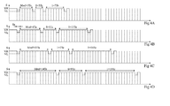
- FIGS. 4A, 4B, 4C and 4D are chronograms illustrating the functioning of the system of the figure 3 . These figures represent four examples of signal S on bus 3 illustrating four possible states for transmission on a second channel.
- the bits of a first channel are coded by pulses in the high state VH on a number of clock periods Te different according to the state 0 or 1 to be transmitted, each bit being separated from the next by a slot at the level of low of fixed duration, for example a clock period Te.
- a data word to be transmitted is preceded by a reference pulse Mref, sent by the circuit 12 and whose duration is measured by the receiver.
- the pulse Mref allows synchronization of the circuits.
- Both circuits 1, 2 have internal clocks with identical frequencies (as close as possible). These internal clocks are of period less than or equal to the period Te.
- the internal clock is used by a counter to determine the value (for example, the number of periods Te) of the pulse Mref and thus be able to discriminate the states 1 and 0 of the following pulses transmitting the bits. If the pulse encoding the bit is shorter than the so-called reference duration of the pulse Mref, the state is 0 (by convention arbitrary). If the pulse encoding the bit has a duration greater than the reference duration, the state is 1.
- the discrimination between the states 0 and 1 of the bits of the first channel is performed by comparing the duration of the pulses with respect to the reference period.
- the transmission block 12 receives not only a first data stream DATA1 to be transmitted and the clock signal CK of period Te (multiple of the internal clock), but also a signal CONF1 which sets the reference duration, therefore the respective durations of the pulses assigned to states 0 and 1 of the first channel.
- the signal CONF1 comes from a coding circuit 16 (CODE) which establishes it as a function of a second data stream DATA2 to be transmitted on the second channel.
- the signal CONF1 configures the circuit 12 to code the reference duration, respectively at 5, 8, 11 and 14 periods Te and codes the bits of the signal DATA1 at the state 0 respectively at 3, 5, 7 and 9 periods of signal Te and the bits in state 1 on respectively 7, 11, 15 and 19 periods Te.
- This coding makes it possible to transmit, on the second channel, a pair of bits to each word of the first channel.
- Receiver side 2 its detection circuit 24 receives the modulated signal on the bus 3. This signal is sent in parallel on a circuit 28 of clock extraction (CK) and on a circuit 26 (DECODE) to extract the data from the second RDATA2 channel.
- the period Te is known and fixed on both sides of the transmission.
- the circuit 28 extracts the period Te (clock CK) of the low level slots present on the signal S.
- the circuit 28 also provides, by decoding the pulse Mref, a configuration signal CONF2 of the detector 24 so that the latter correctly decodes the RDATA1 data according to the duration of the reference (number of periods Te) respectively fixing the states 0 and 1.
- the choice of the number of clock periods Te of difference between the different reference patterns Mref may vary. Preferably, at least three periods of difference between each reference pattern are provided to improve the reliability of the detection.
- the data words are transmitted by byte.
- Each byte is preferably preceded by a reference pulse Mref, which makes it possible to transmit on the second channel at least one bit per byte of the first channel (one bit per byte for one of two reference pulses, two bits per second). byte for one of four reference pulses, etc.).
- the beginning of a transmission is indicated by a specific pattern, for example, a low state during a period Te followed by a high state defining the duration Mref, then a new transition to the low state. This reason will be interpreted as a start of transmission if the receiver of the frame is in a reset state or if it receives successive bits between which the duration Mref is inserted and recognizes the positioning of the duration Mref as a function of the number and the value of the previously received bits.
- the figure 5 is a timing diagram illustrating the transmission of a frame in the master-slave direction and the response of the slave to the master.
- the chronogram of the figure 5 is represented on four lines which are read successively from top to bottom.
- Mref TX1 code
- Circuit 2 can then respond.
- the slave circuit sends a reference pulse SRefTX2 corresponding for example to the coding of the Figure 4B then an 8-bit word "01010011". This first word is followed by a second word "11000000" with the same code TX2.
- the slave circuit switches to a TX4 code corresponding, for example, to the coding of the figure 4D for the next word.
- the period, denoted STe, conditioning the coding on the second channel is set by the slave circuit at a value that is theoretically identical to the period MTe.
- circuit 1 is equipped with detection and decoding circuits similar to circuits 24, 26 and 28 and that circuit 2 is equipped with transmission and coding circuits similar to circuits 12 and 16 of the circuit. 1.
- the coding with the reference duration is preferably performed for each word. This makes it possible to transmit information of the second channel for each word of the first channel. With an encoding over four reference times, each information transmitted is actually a two-bit encoding.
- the implementation of the invention takes advantage of the fact that, in applications using a single-wire bus, the reference times are generally programmable in the transmission and reception circuits. Therefore, the implementation of the invention requires in practice little or no structural modification of the circuits.
- the fact of coding, on a separate channel, two additional bits per data byte of the first channel makes it possible, on a 32-byte frame of the first channel, to code 64 bits on the second channel.
- the number of bits transmitted by the second channel may vary as long as this number is compatible with the maximum expected duration for the data of the first channel. Indeed, the higher the number, the longer the reference period is important.
- the second channel makes it possible to identify the master and / or the slave in a communication system of more than two circuits.
- the second channel makes it possible to encode an identifier, for example, to associate a consumable with a type of device (ink cartridge with respect to printer, telephone battery for a telephone) or with a device. Mark.
- a printer consumable incorporating a slave circuit becomes incompatible with another printer if it is unable to decode the second channel.
- each channel may be dedicated to an application of the master circuit to the same slave circuit.
Landscapes
- Engineering & Computer Science (AREA)
- Theoretical Computer Science (AREA)
- General Engineering & Computer Science (AREA)
- Physics & Mathematics (AREA)
- General Physics & Mathematics (AREA)
- Computer Hardware Design (AREA)
- Computing Systems (AREA)
- Dc Digital Transmission (AREA)
- Small-Scale Networks (AREA)
Abstract
Description
La présente invention concerne de façon générale les circuits électroniques et plus particulièrement, la transmission de données numériques entre deux circuits dans un système de transmission de type maître-esclave. L'invention s'applique plus particulièrement à un protocole de communication sur bus unifilaire.The present invention generally relates to electronic circuits and more particularly to the transmission of digital data between two circuits in a master-slave transmission system. The invention applies more particularly to a communication protocol on single-wire bus.
Un protocole dit sur bus unifilaire est généralement utilisé pour transmettre des données entre plusieurs circuits électroniques en utilisant un seul fil de communication (en plus d'une référence commune ou masse). Dans un protocole unifilaire, un signal de synchronisation et des données (et le cas échéant l'alimentation du récepteur) sont transmis sur le même fil.A single bus protocol is generally used to transmit data between multiple electronic circuits using a single communication wire (in addition to a common reference or ground). In a single-wire protocol, a synchronization signal and data (and possibly receiver power) are transmitted on the same wire.
Un protocole de communication sur bus unifilaire est décrit, par exemple, dans le brevet
Une limitation d'un tel protocole est qu'il est généralement monocanal.A limitation of such a protocol is that it is generally single channel.
Un objet d'un mode de réalisation de la présente invention est de proposer un protocole de communication sur bus unifilaire qui pallie tout ou partie des inconvénients des protocoles connus.An object of an embodiment of the present invention is to propose a bus communication protocol. unifilaire that overcomes all or part of the disadvantages of known protocols.
Un autre objet d'un mode de réalisation de la présente invention est de proposer un protocole bi-canal.Another object of an embodiment of the present invention is to provide a two-channel protocol.
Un autre objet d'un mode de réalisation de la présente invention est de proposer une solution compatible avec le caractère bidirectionnel d'un protocole unifilaire.Another object of an embodiment of the present invention is to propose a solution compatible with the bidirectional character of a single-line protocol.
Pour atteindre tout ou partie des ces objets ainsi que d'autres, il est prévu un procédé de transmission de données sur un bus unifilaire dans lequel :
- un premier canal de communication est défini par des impulsions de durées différentes selon l'état du bit transmis et fonction d'une durée de référence ; et
- un second canal de communication est défini par ladite durée de référence.
- a first communication channel is defined by pulses of different durations depending on the state of the transmitted bit and a function of a reference period; and
- a second communication channel is defined by said reference period.
Selon un mode de réalisation de la présente invention, chaque impulsion du premier canal est d'une durée supérieure ou inférieure à la durée de référence selon l'état du bit transmis.According to an embodiment of the present invention, each pulse of the first channel is of greater or lesser duration than the reference duration depending on the state of the bit transmitted.
Selon un mode de réalisation de la présente invention, ladite durée de référence est choisie dans un ensemble de durées en fonction d'un code transmis sur le second canal.According to an embodiment of the present invention, said reference duration is chosen from a set of durations as a function of a code transmitted on the second channel.
Selon un mode de réalisation de la présente invention, ladite durée de référence est fixe pour un mot de plusieurs bits.According to an embodiment of the present invention, said reference duration is fixed for a word of several bits.
Selon un mode de réalisation de la présente invention, chaque mot du premier canal débute par une impulsion de référence dont la durée fournit la durée de référence.According to an embodiment of the present invention, each word of the first channel starts with a reference pulse whose duration provides the reference duration.
Selon un mode de réalisation de la présente invention, le bus est, au repos, à un premier niveau de tension, lesdites impulsions étant séparées les unes des autres par des périodes de durée fixe à un second niveau de tension.According to one embodiment of the present invention, the bus is, at rest, at a first voltage level, said pulses being separated from each other by periods of fixed duration at a second voltage level.
Selon un mode de réalisation de la présente invention, lesdites impulsions ont des durées correspondant à des multiples desdites périodes de durée fixe.According to one embodiment of the present invention, said pulses have durations corresponding to multiples of said periods of fixed duration.
Selon un mode de réalisation de la présente invention, le premier niveau est supérieur au second.According to one embodiment of the present invention, the first level is greater than the second.
On prévoit également un dispositif d'émission sur un bus unifilaire.There is also provided a transmission device on a single-wire bus.
On prévoit également un dispositif de réception sur bus unifilaire.There is also a reception device on a single-wire bus.
Ces objets, caractéristiques et avantages, ainsi que d'autres seront exposés en détail dans la description suivante de modes de réalisation particuliers faite à titre non-limitatif en relation avec les figures jointes parmi lesquelles :
- la
figure 1 représente, partiellement et sous forme de blocs, deux circuits susceptibles de communiquer selon un protocole maître-esclave sur un bus unifilaire ; - La
figure 2 est un chronogramme illustrant une communication usuelle entre les deux circuits de lafigure 1 ; - la
figure 3 est un schéma blocs partiel d'un mode de mise en oeuvre d'un protocole de communication bi-canal ; - les
figures 4A, 4B, 4C et 4D sont des chronogrammes illustrant le fonctionnement du système illustré enfigure 3 ; et - la
figure 5 est un chronogramme illustrant une transmission bidirectionnelle bi-canal sur bus unifilaire.
- the
figure 1 represents, partially and in block form, two circuits capable of communicating according to a master-slave protocol on a single-wire bus; - The
figure 2 is a chronogram illustrating a usual communication between the two circuits of thefigure 1 ; - the
figure 3 is a partial block diagram of an implementation mode of a two-channel communication protocol; - the
FIGS. 4A, 4B, 4C and 4D are chronograms illustrating the functioning of the system illustrated infigure 3 ; and - the
figure 5 is a timing diagram illustrating bidirectional two-channel transmission on a single-wire bus.
De mêmes éléments ont été désignés par de mêmes références aux différentes figures. Par souci de clarté, seuls les éléments utiles à la compréhension de l'invention ont été représentés et seront décrits. En particulier, les mécanismes de génération des données à transmettre n'ont pas été détaillés, l'invention étant compatible avec les mécanismes habituellement utilisés pour transmettre des données dans un protocole unifilaire. De plus, les circuits d'émission et de réception n'ont pas non plus été détaillés, l'invention étant là encore compatible avec les systèmes usuels.The same elements have been designated with the same references in the various figures. For the sake of clarity, only the elements useful for understanding the invention have been shown and will be described. In particular, the mechanisms for generating the data to be transmitted have not been detailed, the invention being compatible with the mechanisms usually used for transmitting data in a single-line protocol. In addition, the transmission and reception circuits have also not been detailed, the invention being again compatible with the usual systems.
Pour créer un protocole bi-canal, on aurait pu penser faire varier les niveaux de tension sur le bus pour définir un second canal de communication. Toutefois, une telle solution serait peu adaptée à des circuits dans lesquels les niveaux de tension sont susceptibles de varier pour d'autres raisons (longueur de ligne, perturbations diverses, etc.). De plus, cela rendrait plus difficile une récupération d'énergie par le récepteur dans la mesure où cela imposerait un niveau bas plus proche de la masse.To create a two-channel protocol, one might have thought to vary the voltage levels on the bus to define a second communication channel. However, such a solution would be unsuitable for circuits in which the voltage levels are likely to vary for other reasons (line length, various disturbances, etc.). In addition, this would make it more difficult for the receiver to recover energy as it would require a lower level closer to the ground.
La
Chaque circuit 1, 2 comporte, par exemple, un circuit d'émission (SEND) 12, respectivement 22, et un circuit de réception (DET) 14, respectivement 24. Pour une communication du circuit 1 vers le circuit 2, le circuit 1 impose un signal SM sur le bus. Pour une communication du circuit 2 vers le circuit 1, le circuit 2 impose un signal SS sur le bus. Le circuit qui provoque la transmission impose l'horloge sur le bus. Pour simplifier, on a schématisé en
La
Le protocole unifilaire consiste à transmettre, sur le bus 3, à la fois un signal d'horloge ou de synchronisation et les données.The single-wire protocol consists of transmitting, on the bus 3, both a clock or synchronization signal and the data.
Pour transmettre des données du circuit 1 vers le circuit 2, le circuit 1 module le signal SM en amplitude entre deux niveaux VH et VL, par exemple tous deux positifs pour préserver l'alimentation du circuit 2. Cette modulation se retrouve sur le signal S. Le niveau de repos du bus est le niveau haut VH. Dans l'exemple représenté, une transmission est initialisée par un bit de démarrage START dans lequel le signal S est forcé (instant t1) au niveau VL. Cela initialise le circuit esclave 2 et le prépare à recevoir des données. Le circuit 1 module le niveau du signal S au rythme d'un signal d'horloge qui fixe le débit de la transmission. La transmission d'un bit au niveau 0 s'effectue, par exemple, avec une impulsion de niveau VL d'une durée inférieure à la demi-période du signal d'horloge (dans l'exemple représenté, un quart de la période T) alors qu'un niveau 1 est codé avec une impulsion de niveau VL de durée supérieure à la demi-période de ce signal (par exemple trois quarts de la période T). Le circuit esclave 2 détecte la variation d'amplitude et la durée correspondante des impulsions haute et basse pour déterminer la valeur des bits transmis. Une fin de transmission (généralement la fin d'une trame) est codée par le circuit 1 sous la forme d'un état haut (libération du bus) pendant une durée supérieure à la période T.To transmit data from the
Le bus unifilaire SW est un bus de communication bidirectionnel alterné (semiduplex ou half-duplex). Pour transmettre des données du circuit esclave 2 vers circuit maître 1, le circuit esclave modifie la charge qu'il impose sur le fil S selon le niveau du bit qu'il souhaite transmettre. Là encore, le débit de la transmission est fixé par un signal d'horloge au rythme duquel le circuit 2 module l'amplitude du signal S. L'horloge est ici fixée par une horloge interne du circuit 2 alors que le niveau de repos (VH) du bus reste fixé par le circuit 1.The single-wire bus SW is an alternate bidirectional communication bus (semiduplex or half-duplex). To transmit data from the
La
Les
Selon ce mode de réalisation, et à la différence du protocole illustré par la
En pratique, un mot de données à transmettre est précédé d'une impulsion Mref de référence, émise par le circuit 12 et dont la durée est mesurée par le récepteur. L'impulsion Mref permet une synchronisation des circuits. Les deux circuits 1, 2 disposent d'horloges internes ayant des fréquences identiques (les plus proches possibles). Ces horloges internes sont de période inférieure ou égale à la période Te. Côté récepteur, l'horloge interne est utilisée par un compteur pour déterminer la valeur (par exemple, le nombre de périodes Te) de l'impulsion Mref et pouvoir ainsi discriminer les états 1 et 0 des impulsions suivantes transmettant les bits. Si l'impulsion codant le bit est d'une durée inférieure à la durée, dite de référence, de l'impulsion Mref, l'état est 0 (par convention arbitraire). Si l'impulsion codant le bit est d'une durée supérieure à la durée de référence, l'état est 1. La discrimination entre les états 0 et 1 des bits du premier canal s'effectue en comparant la durée des impulsions par rapport à la durée de référence.In practice, a data word to be transmitted is preceded by a reference pulse Mref, sent by the
Pour coder le second canal, on prévoit de rendre variable les durées de référence du premier canal. Ainsi, de façon fonctionnelle et comme l'illustre schématiquement la
Dans l'exemple des
Côté récepteur 2, son circuit de détection 24 reçoit le signal modulé sur le bus 3. Ce signal est envoyé en parallèle sur un circuit 28 d'extraction d'horloge (CK) et sur un circuit 26 (DECODE) chargé d'extraire les données du deuxième canal RDATA2. Selon un premier exemple, la période Te est connue et fixe des deux côtés de la transmission. Selon un autre exemple, le circuit 28 extrait la période Te (horloge CK) des créneaux au niveau bas présents sur le signal S. Le circuit 28 fournit également, en décodant l'impulsion Mref, un signal de configuration CONF2 du détecteur 24 pour que ce dernier décode correctement les données RDATA1 en fonction de la durée de référence (nombre de périodes Te) fixant respectivement les états 0 et 1.
Le choix du nombre de périodes d'horloge Te d'écart entre les différents motifs de référence Mref peut varier. De préférence, on prévoit au moins trois périodes d'écart entre chaque motif de référence pour améliorer la fiabilité de la détection.The choice of the number of clock periods Te of difference between the different reference patterns Mref may vary. Preferably, at least three periods of difference between each reference pattern are provided to improve the reliability of the detection.
On notera que les deux canaux n'interfèrent pas l'un avec l'autre et sont indépendants.Note that the two channels do not interfere with each other and are independent.
Par exemple, et pour être compatible avec les données habituellement transmises dans des systèmes utilisant un bus unifilaire, les mots de données sont transmis par octet. Chaque octet est alors de préférence précédé d'une impulsion de référence Mref, ce qui permet de transmettre sur le second canal au moins un bit par octet du premier canal (un bit par octet pour un codage parmi deux impulsions de référence, deux bits par octet pour un codage parmi quatre impulsions de référence, etc.).For example, and to be compatible with the data usually transmitted in systems using a single-wire bus, the data words are transmitted by byte. Each byte is preferably preceded by a reference pulse Mref, which makes it possible to transmit on the second channel at least one bit per byte of the first channel (one bit per byte for one of two reference pulses, two bits per second). byte for one of four reference pulses, etc.).
Le début d'une transmission est indiqué par un motif spécifique, par exemple, un état bas pendant une période Te suivi d'un état haut définissant la durée Mref, puis d'un nouveau passage à l'état bas. Ce motif sera interprété comme un début de transmission si le récepteur de la trame est dans un état de réinitialisation ou s'il reçoit des bits successifs entre lesquels s'intercale la durée Mref et reconnaît le positionnement de la durée Mref en fonction du nombre et de la valeur des bits précédemment reçus.The beginning of a transmission is indicated by a specific pattern, for example, a low state during a period Te followed by a high state defining the duration Mref, then a new transition to the low state. This reason will be interpreted as a start of transmission if the receiver of the frame is in a reset state or if it receives successive bits between which the duration Mref is inserted and recognizes the positioning of the duration Mref as a function of the number and the value of the previously received bits.
La
Dans le sens esclave vers maître, la période, notée STe, conditionnant le codage sur le second canal, est fixée par le circuit esclave à une valeur théoriquement identique à la période MTe.In the slave-to-master direction, the period, denoted STe, conditioning the coding on the second channel, is set by the slave circuit at a value that is theoretically identical to the period MTe.
Il ressort de ce qui précède que le circuit 1 est équipé de circuits de détection et de décodage similaires aux circuits 24, 26 et 28 et que le circuit 2 est équipé de circuits d'émission et de codage similaires aux circuits 12 et 16 du circuit 1.It follows from the foregoing that
Le codage avec la durée de référence est de préférence effectué pour chaque mot. Cela permet de transmettre une information du deuxième canal pour chaque mot du premier canal. Avec un codage sur quatre durées de référence, chaque information transmise représente en fait un codage sur deux bits.The coding with the reference duration is preferably performed for each word. This makes it possible to transmit information of the second channel for each word of the first channel. With an encoding over four reference times, each information transmitted is actually a two-bit encoding.
On peut se contenter du codage du deuxième canal par l'impulsion de référence MRef ou SRef dans la mesure où les périodes Te côté circuit maître et côté circuit esclave sont a priori identiques.One can be satisfied with the coding of the second channel by the reference pulse MRef or SRef insofar as the periods Te side master circuit and slave circuit side are a priori identical.
Pour le cas où l'on craigne une imprécision par décalage temporel du signal, on peut interpréter la durée des états 1 et des états 0 sur tout l'octet. Cela permet, par exemple par une analyse statistique, de résoudre d'éventuelles imprécisions (si la majorité des impulsions du premier canal respecte ce qui devrait correspondre aux durées associées à la durée de référence, on considère que le code du second canal a la valeur correspondante). Toutefois, cela requiert de compter et de mémoriser le nombre de périodes Te sur tout le mot.For the case where one fears an imprecision by time shift of the signal, one can interpret the duration of
La mise en oeuvre de l'invention tire profit du fait que, dans les applications utilisant un bus unifilaire, les durées de référence sont généralement programmables dans les circuits d'émission et de réception. Par conséquent, la mise en oeuvre de l'invention ne requiert en pratique peu ou pas de modification structurelle des circuits.The implementation of the invention takes advantage of the fact that, in applications using a single-wire bus, the reference times are generally programmable in the transmission and reception circuits. Therefore, the implementation of the invention requires in practice little or no structural modification of the circuits.
Selon un exemple particulier de réalisation, le fait de coder, sur un canal séparé, deux bits supplémentaires par octet de données du premier canal permet, sur une trame de 32 octets du premier canal, de coder 64 bits sur le second canal.According to a particular exemplary embodiment, the fact of coding, on a separate channel, two additional bits per data byte of the first channel makes it possible, on a 32-byte frame of the first channel, to code 64 bits on the second channel.
Le nombre de bits transmis par le second canal peut varier pourvu que ce nombre soit compatible avec la durée maximale attendue pour les données du premier canal. En effet, plus ce nombre est élevé, plus la durée de référence est importante.The number of bits transmitted by the second channel may vary as long as this number is compatible with the maximum expected duration for the data of the first channel. Indeed, the higher the number, the longer the reference period is important.
La présence d'un second canal offre de nombreuses possibilités dans des systèmes exploitant habituellement des bus unifilaires.The presence of a second channel offers many possibilities in systems that usually use single-wire buses.
Par exemple, le deuxième canal permet d'identifier le maître et/ou l'esclave dans un système de communication de plus de deux circuits.For example, the second channel makes it possible to identify the master and / or the slave in a communication system of more than two circuits.
Selon un autre exemple d'application, le deuxième canal permet de coder un identifiant, par exemple, pour associer un consommable à un type d'appareil (cartouche d'encre par rapport à imprimante, batterie de téléphone pour un téléphone) ou à une marque. Par exemple, un consommable d'imprimante intégrant un circuit esclave devient incompatible avec une autre imprimante s'il n'est pas capable de décoder le deuxième canal.According to another application example, the second channel makes it possible to encode an identifier, for example, to associate a consumable with a type of device (ink cartridge with respect to printer, telephone battery for a telephone) or with a device. Mark. For example, a printer consumable incorporating a slave circuit becomes incompatible with another printer if it is unable to decode the second channel.
Selon encore un autre exemple, le canal supplémentaire permet de transmettre, en même temps que les données, une signature de celles-ci. Dans une approche habituelle, une signature est transmise sur le même canal que les données utiles ce qui allonge la durée des trames. Avec les modes de réalisation décrits, la signature peut être intercalée dans la transmission. Tout mécanisme de signature ou de code correcteur d'erreur peut être utilisé.According to yet another example, the additional channel makes it possible to transmit, together with the data, a signature thereof. In a usual approach, a signature is transmitted on the same channel as the useful data which extends the duration of the frames. With the modes of embodiment described, the signature can be inserted in the transmission. Any signature mechanism or error correction code may be used.
Selon encore un autre exemple, le second canal est utilisé pour envoyer une commande particulière aux autres circuits. Par exemple, dans une application d'une batterie par rapport à un équipement ou d'une cartouche par rapport à une imprimante, le deuxième canal peut être utilisé pour transmettre un message indicateur que la batterie ou que la cartouche d'imprimante est vide.According to yet another example, the second channel is used to send a particular command to the other circuits. For example, in an application of a battery with respect to a device or cartridge relative to a printer, the second channel may be used to transmit a message indicating that the battery or the printer cartridge is empty.
Selon encore un autre exemple, chaque canal peut être dédié à une application du circuit maître à destination du même circuit esclave.In yet another example, each channel may be dedicated to an application of the master circuit to the same slave circuit.
Divers modes de réalisation ont été décrits. Diverses variantes et modifications sont à la portée de l'homme du métier. De plus, la mise en oeuvre pratique de l'invention en utilisant des circuits en eux-mêmes connus et en les programmant convenablement est à la portée de l'homme du métier à partir des indications fonctionnelles données ci-dessus. En outre, le choix du nombre de bits de codage du premier canal ainsi que la fréquence de variation de ce codage (dans l'exemple décrit tous les octets) peut varier en fonction des applications.Various embodiments have been described. Various variants and modifications are within the reach of those skilled in the art. In addition, the practical implementation of the invention using circuits known in themselves and programming them properly is within the abilities of those skilled in the art from the functional indications given above. In addition, the choice of the number of coding bits of the first channel as well as the frequency of variation of this coding (in the example describes all the bytes) may vary according to the applications.
Claims (10)
Applications Claiming Priority (1)
| Application Number | Priority Date | Filing Date | Title |
|---|---|---|---|
| FR1056148A FR2963519B1 (en) | 2010-07-27 | 2010-07-27 | COMMUNICATION PROTOCOL ON A UNIFIL BUS |
Publications (2)
| Publication Number | Publication Date |
|---|---|
| EP2413249A1 true EP2413249A1 (en) | 2012-02-01 |
| EP2413249B1 EP2413249B1 (en) | 2013-03-20 |
Family
ID=43533319
Family Applications (1)
| Application Number | Title | Priority Date | Filing Date |
|---|---|---|---|
| EP11175113A Active EP2413249B1 (en) | 2010-07-27 | 2011-07-22 | Communication protocol on single-wire bus |
Country Status (3)
| Country | Link |
|---|---|
| US (2) | US9639500B2 (en) |
| EP (1) | EP2413249B1 (en) |
| FR (1) | FR2963519B1 (en) |
Families Citing this family (28)
| Publication number | Priority date | Publication date | Assignee | Title |
|---|---|---|---|---|
| EP3043407B1 (en) | 2013-11-18 | 2020-04-22 | LG Chem, Ltd. | Positive electrode active material for lithium secondary battery having surface treated using fluoropolymer and manufacturing method therefor |
| US10540226B2 (en) | 2013-12-18 | 2020-01-21 | Qorvo Us, Inc. | Write technique for a bus interface system |
| US10282269B2 (en) | 2013-12-18 | 2019-05-07 | Qorvo Us, Inc. | Read technique for a bus interface system |
| US10579580B2 (en) | 2013-12-18 | 2020-03-03 | Qorvo Us, Inc. | Start of sequence detection for one wire bus |
| US10528502B2 (en) | 2013-12-18 | 2020-01-07 | Qorvo Us, Inc. | Power management system for a bus interface system |
| US9933834B2 (en) * | 2014-10-03 | 2018-04-03 | Qualcomm Incorporated | Clock-free dual-data-rate link with built-in flow control |
| US9652431B2 (en) | 2015-01-26 | 2017-05-16 | Atmel Corporation | Single wire communications using predictive host sampling window |
| US9490999B2 (en) * | 2015-01-28 | 2016-11-08 | Atmel Corporation | Single-wire communications using iterative baud learning |
| WO2016203529A1 (en) * | 2015-06-15 | 2016-12-22 | 富士電機株式会社 | Data communication system, data communication device and sensor device |
| CN108352105B (en) | 2015-12-25 | 2020-12-18 | 麦克赛尔株式会社 | Portable article management device, portable article management method, and portable article management system |
| US10579128B2 (en) * | 2016-03-01 | 2020-03-03 | Qorvo Us, Inc. | Switching power supply for subus slaves |
| US10698847B2 (en) | 2016-03-01 | 2020-06-30 | Qorvo Us, Inc. | One wire bus to RFFE translation system |
| US10437772B2 (en) | 2016-03-24 | 2019-10-08 | Qorvo Us, Inc. | Addressing of slave devices on a single wire communications bus through register map address selection |
| CN106385304B (en) * | 2016-08-31 | 2019-10-25 | 华为技术有限公司 | Data transmission method, equipment and system |
| CN106528484A (en) * | 2016-10-28 | 2017-03-22 | 中国科学院上海微系统与信息技术研究所 | Serial communication method |
| US10558607B2 (en) | 2017-02-01 | 2020-02-11 | Qorvo Us, Inc. | Bus interface system for power extraction |
| EP3584601B1 (en) | 2018-06-18 | 2023-10-18 | NXP USA, Inc. | Time-encoded messaging for radar cascaded synchronization system |
| US10599601B1 (en) | 2019-01-16 | 2020-03-24 | Qorvo Us, Inc. | Single-wire bus (SuBUS) slave circuit and related apparatus |
| WO2020149855A1 (en) | 2019-01-18 | 2020-07-23 | Hewlett-Packard Development Company, L.P. | Print cartridge circuits |
| US11119958B2 (en) | 2019-04-18 | 2021-09-14 | Qorvo Us, Inc. | Hybrid bus apparatus |
| US11226924B2 (en) | 2019-04-24 | 2022-01-18 | Qorvo Us, Inc. | Single-wire bus apparatus supporting slave-initiated operation in a master circuit |
| JP7070496B2 (en) * | 2019-04-24 | 2022-05-18 | オムロン株式会社 | Serial data communication equipment |
| US10983942B1 (en) | 2019-12-11 | 2021-04-20 | Qorvo Us, Inc. | Multi-master hybrid bus apparatus |
| CN112118083A (en) * | 2020-09-02 | 2020-12-22 | 广东瑞德智能科技股份有限公司 | Single-wire half-duplex communication method, communication device and equipment |
| US11409677B2 (en) * | 2020-11-11 | 2022-08-09 | Qorvo Us, Inc. | Bus slave circuit and related single-wire bus apparatus |
| US11489695B2 (en) | 2020-11-24 | 2022-11-01 | Qorvo Us, Inc. | Full-duplex communications over a single-wire bus |
| US11706048B1 (en) | 2021-12-16 | 2023-07-18 | Qorvo Us, Inc. | Multi-protocol bus circuit |
| CN115827535A (en) * | 2022-11-07 | 2023-03-21 | 珠海东之尼电子科技有限公司 | Control method, device and storage medium for single-wire synchronous two-way communication |
Citations (3)
| Publication number | Priority date | Publication date | Assignee | Title |
|---|---|---|---|---|
| US5903607A (en) | 1996-03-28 | 1999-05-11 | Sgs-Thomson Microelectronics S.A. | Method and device for encoding and transmitting bidirectional data from a master circuit to a slave circuit |
| WO2005020081A2 (en) * | 2003-08-22 | 2005-03-03 | 4Links Limited | Communication system using embedded synchronisation |
| WO2010010278A1 (en) * | 2008-07-22 | 2010-01-28 | Stmicroelectronics (Rousset) Sas | Multichannel transmission on unifilar bus |
Family Cites Families (22)
| Publication number | Priority date | Publication date | Assignee | Title |
|---|---|---|---|---|
| US5517015A (en) | 1990-11-19 | 1996-05-14 | Dallas Semiconductor Corporation | Communication module |
| US5495469A (en) | 1994-12-16 | 1996-02-27 | Chrysler Corporation | Communications network, state machine therefor |
| US6532506B1 (en) * | 1998-08-12 | 2003-03-11 | Intel Corporation | Communicating with devices over a bus and negotiating the transfer rate over the same |
| US6735657B1 (en) | 2000-06-30 | 2004-05-11 | Cisco Technology, Inc. | Method and apparatus for connecting two-wire serial interface and single-wire serial interface with high transmission speed |
| US6874052B1 (en) | 2000-09-29 | 2005-03-29 | Lucent Technologies Inc. | Expansion bridge apparatus and method for an I2C bus |
| WO2003096036A1 (en) | 2002-05-08 | 2003-11-20 | Semtech Corporation | Single-wire communication bus for miniature low-power systems |
| TWI236264B (en) | 2002-09-05 | 2005-07-11 | Winbond Electronics Corp | Single wire serial communication protocol method and circuit |
| US8214649B2 (en) | 2004-06-30 | 2012-07-03 | Nokia Corporation | System and method for secure communications between at least one user device and a network entity |
| DE602004026195D1 (en) | 2004-10-21 | 2010-05-06 | Hewlett Packard Development Co | Serial bus system |
| KR20070104939A (en) | 2005-02-25 | 2007-10-29 | 콸콤 인코포레이티드 | Small public-key based digital signatures for authentication |
| US8230151B2 (en) | 2005-04-11 | 2012-07-24 | Linear Technology Corporation | Configurable data port for I2C or single-wire broadcast interface |
| JP2006325191A (en) * | 2005-04-22 | 2006-11-30 | Matsushita Electric Ind Co Ltd | Communication apparatus |
| JP4665617B2 (en) | 2005-06-10 | 2011-04-06 | 沖電気工業株式会社 | Message authentication system, message transmission device, message reception device, message transmission method, message reception method, and program |
| US8296832B2 (en) | 2006-05-10 | 2012-10-23 | Syngrafii Corporation | System, method and computer program, for enabling entry into transactions on a remote basis |
| KR100817031B1 (en) | 2006-08-25 | 2008-03-26 | 주식회사 케이이씨 | Single wire Serial Interface Module |
| KR20080084480A (en) | 2007-03-16 | 2008-09-19 | 삼성전자주식회사 | Method for mutual authenticating between devices using mediated module and system thereof |
| US8285990B2 (en) | 2007-05-14 | 2012-10-09 | Future Wei Technologies, Inc. | Method and system for authentication confirmation using extensible authentication protocol |
| EP2146287B1 (en) | 2008-07-16 | 2012-01-25 | STMicroelectronics (Rousset) SAS | Interface between a two-wire bus and a single-wire bus |
| KR101060901B1 (en) * | 2009-06-04 | 2011-08-30 | 삼성전기주식회사 | Electronic device that sends and receives signals with a single transmission cable |
| FR2963451B1 (en) | 2010-07-27 | 2012-12-07 | St Microelectronics Rousset | AUTHENTICATION OF MULTIPROTOCOL COMMUNICATION |
| CN102385563A (en) | 2010-08-31 | 2012-03-21 | 鸿富锦精密工业(深圳)有限公司 | USB (universal serial bus) port reading and writing device and method of 1-wire bus |
| US8775707B2 (en) | 2010-12-02 | 2014-07-08 | Blackberry Limited | Single wire bus system |
-
2010
- 2010-07-27 FR FR1056148A patent/FR2963519B1/en not_active Expired - Fee Related
-
2011
- 2011-07-22 EP EP11175113A patent/EP2413249B1/en active Active
- 2011-07-25 US US13/189,781 patent/US9639500B2/en active Active
-
2017
- 2017-02-02 US US15/423,479 patent/US11003615B2/en active Active
Patent Citations (3)
| Publication number | Priority date | Publication date | Assignee | Title |
|---|---|---|---|---|
| US5903607A (en) | 1996-03-28 | 1999-05-11 | Sgs-Thomson Microelectronics S.A. | Method and device for encoding and transmitting bidirectional data from a master circuit to a slave circuit |
| WO2005020081A2 (en) * | 2003-08-22 | 2005-03-03 | 4Links Limited | Communication system using embedded synchronisation |
| WO2010010278A1 (en) * | 2008-07-22 | 2010-01-28 | Stmicroelectronics (Rousset) Sas | Multichannel transmission on unifilar bus |
Also Published As
| Publication number | Publication date |
|---|---|
| US20170206182A1 (en) | 2017-07-20 |
| FR2963519A1 (en) | 2012-02-03 |
| EP2413249B1 (en) | 2013-03-20 |
| US20120027104A1 (en) | 2012-02-02 |
| FR2963519B1 (en) | 2012-08-03 |
| US9639500B2 (en) | 2017-05-02 |
| US11003615B2 (en) | 2021-05-11 |
Similar Documents
| Publication | Publication Date | Title |
|---|---|---|
| EP2413249B1 (en) | Communication protocol on single-wire bus | |
| FR2963449A1 (en) | CONVERSION OF A BIFILAR BUS IN A UNIFIL BUS | |
| EP2146287A1 (en) | Interface between a two-wire bus and a single-wire bus | |
| EP2312452A2 (en) | Communication protocol on a one-wire bus | |
| EP2318937B1 (en) | Multichannel transmission on unifilar bus | |
| CN105794168B (en) | Determine the high data rate of the backward channel communication for high speed network initialization | |
| EP0419337A1 (en) | Digital signal encoding method, encoder and decoder for carrying out the method, regeneration method and regenerator therefore | |
| FR2965374A1 (en) | MASTER-SLAVE COMMUNICATION ON A UNIFILARY BUS BETWEEN A MASTER CIRCUIT AND AT LEAST TWO SLAVE CIRCUITS | |
| EP1298812B1 (en) | Method and apparatus for decoding an incoming ultra wideband impulse signal, in particular for a wireless communication system | |
| FR3001594A1 (en) | METHOD, DEVICE AND COMPUTER PROGRAM FOR DIGITAL TRANSMISSION OF MESSAGES | |
| CN101529790B (en) | Serial digital data communication interface | |
| EP2286538B1 (en) | A high speed data transmission method and corresponding devices | |
| FR2700086A1 (en) | A method of transmitting high bit rate information by multiple block allocation, associated receiving method, and receiving device for implementing same. | |
| EP2368192B1 (en) | Transmission over i2c bus | |
| FR2918522A1 (en) | METHOD AND DEVICE FOR PROCESSING A PULSE TRAIN OF A MODULATED SIGNAL, IN PARTICULAR A MODULAR ULTRA-WIDEBAND SIGNAL, BY DIGITAL MODULATION BY INTERVAL OF PULSES | |
| FR2990784A1 (en) | COMMUNICATION MEMBER OF A MULTI-STATE CAN FD TYPE COMMUNICATION NETWORK COMPATIBLE WITH CAN HS TYPE COMMUNICATION DEVICES | |
| EP0082054B1 (en) | Method of synchronising transceiver sets of a frequency-hopping network, and set for carrying out this method | |
| FR2597689A1 (en) | DEVICE FOR THE RECOVERY OF RHYTHM SUITABLE IN PARTICULAR FOR AN INFORMATION TRANSMISSION SYSTEM USING IN A SENSE OF TRANSMISSION THE PRINCIPLE SAID OF A.M.R.T. | |
| EP0211438B1 (en) | Apparatus for transmitting packets in an asynchronous time network and method for coding the silences | |
| EP0726666B1 (en) | Interface circuit between communication media in a home network | |
| FR2912014A1 (en) | Ultra wide band pulse generator for transmitting ternary digital data, has table supplying words of selected digital word set that codes different events by different amplitude variations to reduce bandwidth of pulses from generator | |
| EP1791266B1 (en) | UWB signal pulse receiver and related method | |
| US7539803B2 (en) | Bi-directional interface for low data rate application | |
| FR2646742A1 (en) | DEVICE FOR SYNCHRONIZING A PSEUDO-BINARY SIGNAL WITH A REGENERATED CLOCK SIGNAL WITH PHASE HOPES | |
| US20230269118A1 (en) | Single wire serial communication using pulse width modulation in a daisy chain architecture |
Legal Events
| Date | Code | Title | Description |
|---|---|---|---|
| 17P | Request for examination filed |
Effective date: 20110722 |
|
| AK | Designated contracting states |
Kind code of ref document: A1 Designated state(s): AL AT BE BG CH CY CZ DE DK EE ES FI FR GB GR HR HU IE IS IT LI LT LU LV MC MK MT NL NO PL PT RO RS SE SI SK SM TR |
|
| AX | Request for extension of the european patent |
Extension state: BA ME |
|
| PUAI | Public reference made under article 153(3) epc to a published international application that has entered the european phase |
Free format text: ORIGINAL CODE: 0009012 |
|
| RIC1 | Information provided on ipc code assigned before grant |
Ipc: G06F 13/42 20060101AFI20120803BHEP |
|
| GRAP | Despatch of communication of intention to grant a patent |
Free format text: ORIGINAL CODE: EPIDOSNIGR1 |
|
| GRAS | Grant fee paid |
Free format text: ORIGINAL CODE: EPIDOSNIGR3 |
|
| GRAA | (expected) grant |
Free format text: ORIGINAL CODE: 0009210 |
|
| AK | Designated contracting states |
Kind code of ref document: B1 Designated state(s): AL AT BE BG CH CY CZ DE DK EE ES FI FR GB GR HR HU IE IS IT LI LT LU LV MC MK MT NL NO PL PT RO RS SE SI SK SM TR |
|
| REG | Reference to a national code |
Ref country code: GB Ref legal event code: FG4D Free format text: NOT ENGLISH |
|
| REG | Reference to a national code |
Ref country code: CH Ref legal event code: EP |
|
| REG | Reference to a national code |
Ref country code: IE Ref legal event code: FG4D Free format text: LANGUAGE OF EP DOCUMENT: FRENCH |
|
| REG | Reference to a national code |
Ref country code: AT Ref legal event code: REF Ref document number: 602452 Country of ref document: AT Kind code of ref document: T Effective date: 20130415 |
|
| REG | Reference to a national code |
Ref country code: DE Ref legal event code: R096 Ref document number: 602011001115 Country of ref document: DE Effective date: 20130516 |
|
| PG25 | Lapsed in a contracting state [announced via postgrant information from national office to epo] |
Ref country code: LT Free format text: LAPSE BECAUSE OF FAILURE TO SUBMIT A TRANSLATION OF THE DESCRIPTION OR TO PAY THE FEE WITHIN THE PRESCRIBED TIME-LIMIT Effective date: 20130320 Ref country code: SE Free format text: LAPSE BECAUSE OF FAILURE TO SUBMIT A TRANSLATION OF THE DESCRIPTION OR TO PAY THE FEE WITHIN THE PRESCRIBED TIME-LIMIT Effective date: 20130320 Ref country code: BG Free format text: LAPSE BECAUSE OF FAILURE TO SUBMIT A TRANSLATION OF THE DESCRIPTION OR TO PAY THE FEE WITHIN THE PRESCRIBED TIME-LIMIT Effective date: 20130620 Ref country code: NO Free format text: LAPSE BECAUSE OF FAILURE TO SUBMIT A TRANSLATION OF THE DESCRIPTION OR TO PAY THE FEE WITHIN THE PRESCRIBED TIME-LIMIT Effective date: 20130620 Ref country code: ES Free format text: LAPSE BECAUSE OF FAILURE TO SUBMIT A TRANSLATION OF THE DESCRIPTION OR TO PAY THE FEE WITHIN THE PRESCRIBED TIME-LIMIT Effective date: 20130701 |
|
| REG | Reference to a national code |
Ref country code: AT Ref legal event code: MK05 Ref document number: 602452 Country of ref document: AT Kind code of ref document: T Effective date: 20130320 |
|
| REG | Reference to a national code |
Ref country code: LT Ref legal event code: MG4D |
|
| PG25 | Lapsed in a contracting state [announced via postgrant information from national office to epo] |
Ref country code: SI Free format text: LAPSE BECAUSE OF FAILURE TO SUBMIT A TRANSLATION OF THE DESCRIPTION OR TO PAY THE FEE WITHIN THE PRESCRIBED TIME-LIMIT Effective date: 20130320 Ref country code: FI Free format text: LAPSE BECAUSE OF FAILURE TO SUBMIT A TRANSLATION OF THE DESCRIPTION OR TO PAY THE FEE WITHIN THE PRESCRIBED TIME-LIMIT Effective date: 20130320 Ref country code: GR Free format text: LAPSE BECAUSE OF FAILURE TO SUBMIT A TRANSLATION OF THE DESCRIPTION OR TO PAY THE FEE WITHIN THE PRESCRIBED TIME-LIMIT Effective date: 20130621 Ref country code: LV Free format text: LAPSE BECAUSE OF FAILURE TO SUBMIT A TRANSLATION OF THE DESCRIPTION OR TO PAY THE FEE WITHIN THE PRESCRIBED TIME-LIMIT Effective date: 20130320 |
|
| REG | Reference to a national code |
Ref country code: NL Ref legal event code: VDEP Effective date: 20130320 |
|
| PG25 | Lapsed in a contracting state [announced via postgrant information from national office to epo] |
Ref country code: HR Free format text: LAPSE BECAUSE OF FAILURE TO SUBMIT A TRANSLATION OF THE DESCRIPTION OR TO PAY THE FEE WITHIN THE PRESCRIBED TIME-LIMIT Effective date: 20130320 Ref country code: RS Free format text: LAPSE BECAUSE OF FAILURE TO SUBMIT A TRANSLATION OF THE DESCRIPTION OR TO PAY THE FEE WITHIN THE PRESCRIBED TIME-LIMIT Effective date: 20130320 |
|
| PG25 | Lapsed in a contracting state [announced via postgrant information from national office to epo] |
Ref country code: CZ Free format text: LAPSE BECAUSE OF FAILURE TO SUBMIT A TRANSLATION OF THE DESCRIPTION OR TO PAY THE FEE WITHIN THE PRESCRIBED TIME-LIMIT Effective date: 20130320 Ref country code: AT Free format text: LAPSE BECAUSE OF FAILURE TO SUBMIT A TRANSLATION OF THE DESCRIPTION OR TO PAY THE FEE WITHIN THE PRESCRIBED TIME-LIMIT Effective date: 20130320 Ref country code: NL Free format text: LAPSE BECAUSE OF FAILURE TO SUBMIT A TRANSLATION OF THE DESCRIPTION OR TO PAY THE FEE WITHIN THE PRESCRIBED TIME-LIMIT Effective date: 20130320 Ref country code: SK Free format text: LAPSE BECAUSE OF FAILURE TO SUBMIT A TRANSLATION OF THE DESCRIPTION OR TO PAY THE FEE WITHIN THE PRESCRIBED TIME-LIMIT Effective date: 20130320 Ref country code: PT Free format text: LAPSE BECAUSE OF FAILURE TO SUBMIT A TRANSLATION OF THE DESCRIPTION OR TO PAY THE FEE WITHIN THE PRESCRIBED TIME-LIMIT Effective date: 20130722 Ref country code: IS Free format text: LAPSE BECAUSE OF FAILURE TO SUBMIT A TRANSLATION OF THE DESCRIPTION OR TO PAY THE FEE WITHIN THE PRESCRIBED TIME-LIMIT Effective date: 20130720 Ref country code: EE Free format text: LAPSE BECAUSE OF FAILURE TO SUBMIT A TRANSLATION OF THE DESCRIPTION OR TO PAY THE FEE WITHIN THE PRESCRIBED TIME-LIMIT Effective date: 20130320 Ref country code: RO Free format text: LAPSE BECAUSE OF FAILURE TO SUBMIT A TRANSLATION OF THE DESCRIPTION OR TO PAY THE FEE WITHIN THE PRESCRIBED TIME-LIMIT Effective date: 20130320 |
|
| PG25 | Lapsed in a contracting state [announced via postgrant information from national office to epo] |
Ref country code: PL Free format text: LAPSE BECAUSE OF FAILURE TO SUBMIT A TRANSLATION OF THE DESCRIPTION OR TO PAY THE FEE WITHIN THE PRESCRIBED TIME-LIMIT Effective date: 20130320 Ref country code: CY Free format text: LAPSE BECAUSE OF FAILURE TO SUBMIT A TRANSLATION OF THE DESCRIPTION OR TO PAY THE FEE WITHIN THE PRESCRIBED TIME-LIMIT Effective date: 20130320 |
|
| PGFP | Annual fee paid to national office [announced via postgrant information from national office to epo] |
Ref country code: FR Payment date: 20130722 Year of fee payment: 3 |
|
| PLBE | No opposition filed within time limit |
Free format text: ORIGINAL CODE: 0009261 |
|
| STAA | Information on the status of an ep patent application or granted ep patent |
Free format text: STATUS: NO OPPOSITION FILED WITHIN TIME LIMIT |
|
| BERE | Be: lapsed |
Owner name: STMICROELECTRONICS (ROUSSET) SAS Effective date: 20130731 |
|
| PG25 | Lapsed in a contracting state [announced via postgrant information from national office to epo] |
Ref country code: DK Free format text: LAPSE BECAUSE OF FAILURE TO SUBMIT A TRANSLATION OF THE DESCRIPTION OR TO PAY THE FEE WITHIN THE PRESCRIBED TIME-LIMIT Effective date: 20130320 |
|
| 26N | No opposition filed |
Effective date: 20140102 |
|
| PG25 | Lapsed in a contracting state [announced via postgrant information from national office to epo] |
Ref country code: MC Free format text: LAPSE BECAUSE OF FAILURE TO SUBMIT A TRANSLATION OF THE DESCRIPTION OR TO PAY THE FEE WITHIN THE PRESCRIBED TIME-LIMIT Effective date: 20130320 Ref country code: IT Free format text: LAPSE BECAUSE OF FAILURE TO SUBMIT A TRANSLATION OF THE DESCRIPTION OR TO PAY THE FEE WITHIN THE PRESCRIBED TIME-LIMIT Effective date: 20130320 |
|
| REG | Reference to a national code |
Ref country code: DE Ref legal event code: R097 Ref document number: 602011001115 Country of ref document: DE Effective date: 20140102 |
|
| REG | Reference to a national code |
Ref country code: IE Ref legal event code: MM4A |
|
| PG25 | Lapsed in a contracting state [announced via postgrant information from national office to epo] |
Ref country code: BE Free format text: LAPSE BECAUSE OF NON-PAYMENT OF DUE FEES Effective date: 20130731 |
|
| PG25 | Lapsed in a contracting state [announced via postgrant information from national office to epo] |
Ref country code: IE Free format text: LAPSE BECAUSE OF NON-PAYMENT OF DUE FEES Effective date: 20130722 |
|
| REG | Reference to a national code |
Ref country code: CH Ref legal event code: PL |
|
| REG | Reference to a national code |
Ref country code: FR Ref legal event code: ST Effective date: 20150331 |
|
| PG25 | Lapsed in a contracting state [announced via postgrant information from national office to epo] |
Ref country code: CH Free format text: LAPSE BECAUSE OF NON-PAYMENT OF DUE FEES Effective date: 20140731 Ref country code: LI Free format text: LAPSE BECAUSE OF NON-PAYMENT OF DUE FEES Effective date: 20140731 |
|
| PG25 | Lapsed in a contracting state [announced via postgrant information from national office to epo] |
Ref country code: FR Free format text: LAPSE BECAUSE OF NON-PAYMENT OF DUE FEES Effective date: 20140731 Ref country code: SM Free format text: LAPSE BECAUSE OF FAILURE TO SUBMIT A TRANSLATION OF THE DESCRIPTION OR TO PAY THE FEE WITHIN THE PRESCRIBED TIME-LIMIT Effective date: 20130320 |
|
| PG25 | Lapsed in a contracting state [announced via postgrant information from national office to epo] |
Ref country code: MT Free format text: LAPSE BECAUSE OF FAILURE TO SUBMIT A TRANSLATION OF THE DESCRIPTION OR TO PAY THE FEE WITHIN THE PRESCRIBED TIME-LIMIT Effective date: 20130320 Ref country code: TR Free format text: LAPSE BECAUSE OF FAILURE TO SUBMIT A TRANSLATION OF THE DESCRIPTION OR TO PAY THE FEE WITHIN THE PRESCRIBED TIME-LIMIT Effective date: 20130320 |
|
| PG25 | Lapsed in a contracting state [announced via postgrant information from national office to epo] |
Ref country code: LU Free format text: LAPSE BECAUSE OF NON-PAYMENT OF DUE FEES Effective date: 20130722 Ref country code: HU Free format text: LAPSE BECAUSE OF FAILURE TO SUBMIT A TRANSLATION OF THE DESCRIPTION OR TO PAY THE FEE WITHIN THE PRESCRIBED TIME-LIMIT; INVALID AB INITIO Effective date: 20110722 Ref country code: MK Free format text: LAPSE BECAUSE OF FAILURE TO SUBMIT A TRANSLATION OF THE DESCRIPTION OR TO PAY THE FEE WITHIN THE PRESCRIBED TIME-LIMIT Effective date: 20130320 |
|
| GBPC | Gb: european patent ceased through non-payment of renewal fee |
Effective date: 20150722 |
|
| PG25 | Lapsed in a contracting state [announced via postgrant information from national office to epo] |
Ref country code: GB Free format text: LAPSE BECAUSE OF NON-PAYMENT OF DUE FEES Effective date: 20150722 |
|
| PG25 | Lapsed in a contracting state [announced via postgrant information from national office to epo] |
Ref country code: AL Free format text: LAPSE BECAUSE OF FAILURE TO SUBMIT A TRANSLATION OF THE DESCRIPTION OR TO PAY THE FEE WITHIN THE PRESCRIBED TIME-LIMIT Effective date: 20130320 |
|
| PGFP | Annual fee paid to national office [announced via postgrant information from national office to epo] |
Ref country code: DE Payment date: 20230620 Year of fee payment: 13 |