EP2409841B1 - Inkjet printer and inkjet printing method - Google Patents
Inkjet printer and inkjet printing method Download PDFInfo
- Publication number
- EP2409841B1 EP2409841B1 EP10753413.3A EP10753413A EP2409841B1 EP 2409841 B1 EP2409841 B1 EP 2409841B1 EP 10753413 A EP10753413 A EP 10753413A EP 2409841 B1 EP2409841 B1 EP 2409841B1
- Authority
- EP
- European Patent Office
- Prior art keywords
- image
- clear ink
- print medium
- colored image
- colored
- Prior art date
- Legal status (The legal status is an assumption and is not a legal conclusion. Google has not performed a legal analysis and makes no representation as to the accuracy of the status listed.)
- Not-in-force
Links
- 238000000034 method Methods 0.000 title claims description 10
- 238000007641 inkjet printing Methods 0.000 title claims description 6
- 230000007246 mechanism Effects 0.000 claims description 107
- 239000011248 coating agent Substances 0.000 claims description 27
- 238000000576 coating method Methods 0.000 claims description 27
- 238000007639 printing Methods 0.000 description 32
- 230000004048 modification Effects 0.000 description 20
- 238000012986 modification Methods 0.000 description 20
- 239000000470 constituent Substances 0.000 description 12
- 230000006872 improvement Effects 0.000 description 11
- 238000004519 manufacturing process Methods 0.000 description 9
- 239000011159 matrix material Substances 0.000 description 9
- 230000008030 elimination Effects 0.000 description 7
- 238000003379 elimination reaction Methods 0.000 description 7
- 230000015572 biosynthetic process Effects 0.000 description 4
- 238000007645 offset printing Methods 0.000 description 4
- 238000005242 forging Methods 0.000 description 3
- 239000000463 material Substances 0.000 description 3
- 239000011247 coating layer Substances 0.000 description 1
- 239000003086 colorant Substances 0.000 description 1
- 238000001035 drying Methods 0.000 description 1
- 238000005562 fading Methods 0.000 description 1
- 238000005286 illumination Methods 0.000 description 1
- 230000002265 prevention Effects 0.000 description 1
- 230000008569 process Effects 0.000 description 1
- 230000001681 protective effect Effects 0.000 description 1
- 239000011241 protective layer Substances 0.000 description 1
- 230000000007 visual effect Effects 0.000 description 1
- 239000002699 waste material Substances 0.000 description 1
Images


Classifications
-
- B—PERFORMING OPERATIONS; TRANSPORTING
- B41—PRINTING; LINING MACHINES; TYPEWRITERS; STAMPS
- B41J—TYPEWRITERS; SELECTIVE PRINTING MECHANISMS, i.e. MECHANISMS PRINTING OTHERWISE THAN FROM A FORME; CORRECTION OF TYPOGRAPHICAL ERRORS
- B41J11/00—Devices or arrangements of selective printing mechanisms, e.g. ink-jet printers or thermal printers, for supporting or handling copy material in sheet or web form
- B41J11/0015—Devices or arrangements of selective printing mechanisms, e.g. ink-jet printers or thermal printers, for supporting or handling copy material in sheet or web form for treating before, during or after printing or for uniform coating or laminating the copy material before or after printing
-
- B—PERFORMING OPERATIONS; TRANSPORTING
- B41—PRINTING; LINING MACHINES; TYPEWRITERS; STAMPS
- B41J—TYPEWRITERS; SELECTIVE PRINTING MECHANISMS, i.e. MECHANISMS PRINTING OTHERWISE THAN FROM A FORME; CORRECTION OF TYPOGRAPHICAL ERRORS
- B41J11/00—Devices or arrangements of selective printing mechanisms, e.g. ink-jet printers or thermal printers, for supporting or handling copy material in sheet or web form
- B41J11/0065—Means for printing without leaving a margin on at least one edge of the copy material, e.g. edge-to-edge printing
-
- B—PERFORMING OPERATIONS; TRANSPORTING
- B41—PRINTING; LINING MACHINES; TYPEWRITERS; STAMPS
- B41J—TYPEWRITERS; SELECTIVE PRINTING MECHANISMS, i.e. MECHANISMS PRINTING OTHERWISE THAN FROM A FORME; CORRECTION OF TYPOGRAPHICAL ERRORS
- B41J2/00—Typewriters or selective printing mechanisms characterised by the printing or marking process for which they are designed
- B41J2/005—Typewriters or selective printing mechanisms characterised by the printing or marking process for which they are designed characterised by bringing liquid or particles selectively into contact with a printing material
- B41J2/01—Ink jet
- B41J2/21—Ink jet for multi-colour printing
- B41J2/2107—Ink jet for multi-colour printing characterised by the ink properties
- B41J2/2114—Ejecting specialized liquids, e.g. transparent or processing liquids
-
- B—PERFORMING OPERATIONS; TRANSPORTING
- B41—PRINTING; LINING MACHINES; TYPEWRITERS; STAMPS
- B41M—PRINTING, DUPLICATING, MARKING, OR COPYING PROCESSES; COLOUR PRINTING
- B41M5/00—Duplicating or marking methods; Sheet materials for use therein
- B41M5/0011—Pre-treatment or treatment during printing of the recording material, e.g. heating, irradiating
-
- B—PERFORMING OPERATIONS; TRANSPORTING
- B41—PRINTING; LINING MACHINES; TYPEWRITERS; STAMPS
- B41M—PRINTING, DUPLICATING, MARKING, OR COPYING PROCESSES; COLOUR PRINTING
- B41M5/00—Duplicating or marking methods; Sheet materials for use therein
- B41M5/0029—Formation of a transparent pattern using a liquid marking fluid
-
- B—PERFORMING OPERATIONS; TRANSPORTING
- B41—PRINTING; LINING MACHINES; TYPEWRITERS; STAMPS
- B41M—PRINTING, DUPLICATING, MARKING, OR COPYING PROCESSES; COLOUR PRINTING
- B41M7/00—After-treatment of prints, e.g. heating, irradiating, setting of the ink, protection of the printed stock
Definitions
- the present invention relates to an inkjet printer for performing printing in an inkjet manner and an inkjet printing method.
- forming a hologram or a code image (so-called a watermark) on a printed material is performed in order to improve security such as prevention of forgery of printed material.
- a technique of forming a transparent image on a print medium with clear toner is known.
- the print medium is sheet-like or thin plate-like, and the colored image is formed on one main surface of the print medium and the code image is formed on the other main surface of the print medium.
- the clear ink may be ultraviolet visible ink.
- the inkjet printer further comprises another ejection mechanism for ejecting fine droplets of colored ink from a plurality of outlets; wherein the another ejection mechanism is controlled together with the moving mechanism by the print controller, to form the colored image on the print medium.
- the ejection mechanism 31b at the (+Y) side of the ejection mechanism 31a ejects K (black) colored ink
- the ejection mechanism 31b at the (+Y) side of the ejection mechanism 31a ejects C (cyan) colored ink
- the ejection mechanism 31c at the (+Y) side of the ejection mechanism 31b ejects M (magenta) colored ink
- the ejection mechanism 31d at the (+Y) side of the ejection mechanism 31c ejects Y (yellow) colored ink in the ejection part 3, the ejection mechanism 32 lying on the outermost (+Y) side in Fig. 1 ejects clear ink.
- invisible ink which is made visible by irradiation of ultraviolet i.e., ultraviolet visible ink
- invisible ink which is made visible by irradiation of ultraviolet (i.e., ultraviolet visible ink) is utilized as the clear ink.
- Step S12 forming of the colored image (Step S12) and coating of the colored image (Step S13) are sequentially performed for each portion of the print medium 9 in the Y direction, and therefore, for the whole print medium 9, forming of the colored image (Step S12) and coating of the colored image (Step S13) are performed almost in parallel (the same applies to after-mentioned Step S22 and Step S23 in Fig. 6 ).
- each dot of the colored image is coated with a dot of clear ink having the same size.
- the dots of the colored image may be coated with dots of the clear ink having larger size than the dots of the colored image. Therefore, if a landing position of the clear ink (i.e., the position where a droplet of the clear ink is applied) is slightly off from a dot of the colored image, the dot of the colored image is certainly coated with the clear ink.
- a tint part of the colored image there may be a case where the tint part is uniformly coated with the clear ink over the whole surface with no space, and ejection of the clear ink is controlled so that a total area of dots of the clear ink which is applied onto the tint part becomes a predetermined percent of an area of the tint part (the percent is a predetermined percent more than 0% and less than 100%, for example 50%), to apply the clear ink onto the tint part uniformly. Since the total area of dots of the clear ink is made less than the area of the tint part, drying of the colored ink in the tint part is promoted.
- the clear ink is ejected toward the blank area 93 on the first main surface 91 of the print medium 9 (in the present embodiment, toward a portion of the blank area 93 lying on the (+X) side or (-X) side of the colored image print area 92) in parallel with coating the colored image with the clear ink in Step S13, to thereby form the code image on the blank area 93 with the clear ink (Step S14).
- the coating of the colored image and forming of the code image for the blank area 93 around the colored image i.e., formation of the code image performed with avoiding the colored image
- the identical clear ink ejected from the one ejection mechanism 32 is performed on the first main surface 91 of the print medium 9 where the colored image is formed.
- the original print medium 9 is easily distinguished from a copy of the print medium 9 or the like, and security of the colored image on the print medium 9 is improved.
- the inkjet printer 1 the above-mentioned printing is sequentially performed for a plurality of print media 9 (the same applies to the following other embodiments).
- the coating of the colored image and the forming of the code image are performed with the same clear ink ejected from the one ejection mechanism 32. Therefore, structure of the inkjet printer 1 is simplified, and improvement of wear resistance and improvement of security of the colored image can be achieved while reducing manufacturing cost of the apparatus. In addition, printing cost for the print medium 9 can be reduced.
- the ultraviolet visible ink is utilized as the clear ink
- readout of the code image on the print medium 9 can be easily performed with use of relatively inexpensive and easy-to-use black light or the like, and without using an expensive instrument, equipment or the like.
- the code image is made grayscale, inability to detect the code image due to a short ejection amount of the clear ink or exposure of the code image under normal illumination due to an excessive ejection amount of the clear ink is prevented and forming code information with high accuracy is achieved.
- outlets used for the forming of the code image are made different from outlets used for the coating of the colored image in the ejection mechanism 32. Therefore, ejection control of the clear ink from the outlets in the ejection mechanism 32 which are used for the coating of the colored image is performed on the basis of only the first halftone image data, and ejection control of the clear ink from the outlets which are used for the forming of the code image is performed on the basis of only the second halftone image data. As the result, control of the ejection mechanism 32 is simplified.
- the code image is formed on the blank area 93 around the colored image, the coating of the colored image and the forming of the code image can be easily performed in parallel. As the result, the printing for the print medium 9 can be performed quickly.
- the moving mechanism 2 for moving the print medium 9 relative to the ejection part 3 can be simplified and the printing for the print medium 9 can be performed more quickly.
- the moving mechanism 2 used for the coating of the colored image and the forming of the code image is controlled together with the ejection mechanisms 31a to 31d of the ejection part 3 by the print controller 4, to perform forming the colored image on the print medium 9.
- the code image is formed on the blank area 93 around the colored image on the first main surface 91 of the print medium 9 shown in Fig. 2 .
- a code image may be formed on the colored image formed on the colored image print area 92.
- ejection amounts of the clear ink from a group of outlets, which is opposed to the colored image print area 92, in the ejection mechanism 32 are set at a predetermined amount so as to uniformly coat the whole colored image print area 92 with the clear ink with no space, and furthermore, control to increase the ejection amount of the clear ink from an outlet, which corresponds to each dot of the code image, by approximately 20% to 30% of the above predetermined amount is performed by the print controller 4 on the basis of the second halftone image data.
- the colored image print area 92 where the colored image is formed is coated with the clear ink over the whole surface, and heights of portions, corresponding to the code image, in the coating layer of the clear ink are made higher than that of the surround.
- the code image since the code image is formed on the colored image, visual recognition of the code image can be made more difficult in the state where ambient light is irradiated.
- the code image may be formed on both the colored image and the blank area 93.
- FIG. 5 is a view showing a constitution of the inkjet printer 1a in accordance with the second embodiment.
- the constituents of the inkjet printer 1a are same as those of the inkjet printer 1 shown in Fig. 1 except for the point where the moving mechanism 2 has a reversal mechanism 24 at the lower side of the guide 22, and in the following description, constituents corresponding to respective constituents of the inkjet printer 1 are denoted by the same reference signs.
- Fig. 6 is a flowchart showing an operation flow of printing by the inkjet printer 1a.
- the first halftone image data representing the colored image and the second halftone image data representing the code image are generated in the print controller 4 in the same manner as the first embodiment (Step S21).
- the print medium 9 is supplied from the supply part 51 onto a stage 21 to be held thereon, and the moving mechanism 2 and the ejection mechanisms 31a to 31d, 32 in the ejection part 3 are controlled by the print controller 4, thereby to form the colored image on the colored image print area 92 (see Fig. 2 ) of the first main surface 91 of the print medium 9 (Step S22) and to perform coating the colored image with the clear ink (Step S23).
- the print medium 9 where the forming of the colored image and the coating of the colored image are completed moves in a counterclockwise direction in Fig. 5 by movement of the belt inside the guide 22 of the moving mechanism 2, and it reaches at the reversal mechanism 24 without being withdrawn by the elimination part 52.
- the print medium 9 is reversed by the reversal mechanism 24, and the first main surface 91 which is one main surface on which the colored image has been formed is held on the stage 21 by suction (Step S24).
- the print medium 9 moves in the counterclockwise direction to lie at the lower side of the ejection part 3 and a second main surface 94 (see Fig. 2 ) of the print medium 9 which is the other main surface is opposite to the ejection mechanism 32.
- the moving mechanism 2 and the ejection mechanism 32 are controlled by the print controller 4, and therefore ejection of the clear ink toward the second main surface 94 of the print medium 9 is performed to perform forming of the code image on the second main surface 94 (Step S25).
- the print medium 9 where the forming of the code image is completed is withdrawn by the elimination part 52.
- the code image is formed on the second main surface 94 which is different from the first main surface 91 on which the colored image is formed.
- the print medium 9 is supplied from the supply part 51 onto a stage 21 to be held thereon, and the moving mechanism 2 and the ejection mechanism 32 in the ejection part 3 are controlled by print controller 4. Therefore, the clear ink is uniformly ejected from outlets, which are opposed to the colored image print area 92 (see Fig. 2 ) of the print medium 9 on which the colored image is to be formed, out of the plurality of outlets in the ejection mechanism 32 toward the colored image print area 92, to perform surface modification of the colored image print area 92 on the first main surface 91 (see Fig. 2 ) of the print medium 9 (Step S32). In addition, ejection of the clear ink from outlets, which are opposed to the blank area 93 (see Fig.
- the colored ink is ejected toward portions of the colored image print area 92 (i.e., the colored image print area 92 after the surface modification) having passed under the ejection mechanism 32, to perform forming of the colored image (Step S34).
- modifying the surface and forming the code image (Step S32, S33), and forming the colored image (Step S34) are sequentially performed on each portion of the print medium 9 in the Y direction, and therefore for the whole print medium 9, modifying the surface and forming the code image (Step S32, S33), and forming the colored image (Step S34) are performed in almost parallel.
- the code image is formed on the blank area 93 around the colored image
- the surface modification of the print medium 9 can be easily performed in parallel with the forming of the code image. Therefore, the printing for the print medium 9 can be performed quickly.
- the surface modification with the clear ink may be also performed on the blank area 93.
- the moving mechanism 2 used for the surface modification of the print medium 9 and the forming of the code image is controlled together with the ejection mechanisms 31a to 31d in the ejection part 3 by the print controller 4, to perform the forming of the colored image on the print medium 9.
- the print medium 9 where the surface modification and the forming of the colored image are completed reaches at the reversal mechanism 24 without being withdrawn by the elimination part 52, and it is reversed by the reversal mechanism 24 (Step S44). After that, the print medium 9 moves to the lower side of the ejection part 3 and the moving mechanism 2 and the ejection mechanism 32 are controlled by the print controller 4 to perform forming of the code image on the second main surface 94 of the print medium 9 (Step S45). The print medium 9 where the forming of the code image is completed is withdrawn by the elimination part 52.
- the surface modification of the print medium 9 and the forming of the code image are performed with the same clear ink ejected from the one ejection mechanism 32. Therefore, the surface modification of the print medium 9 and the forming of high accuracy and high quality colored image by the modification, and improvement of security of the colored image on the print medium 9 can be achieved while reducing manufacturing cost of the apparatus without complicating structure of the inkjet printer 1c in a similar fashion to the third embodiment. In addition, printing cost for the print medium 9 can be reduced. Furthermore, control of the ejection mechanism 32 is simplified since the code image is formed on the second main surface 94.
- the coating of the colored image and the forming of the code image are performed with the same clear ink ejected from the one ejection mechanism 32 in a similar fashion to the first embodiment. Therefore, improvement of wear resistance and improvement of security of the colored image can be achieved while reducing manufacturing cost of the apparatus without complicating structure of the inkjet printer 1d.
- the scanner 102 may be omitted. Also another printing apparatus such as an electrophotographic printer may be provided as substitute for the offset printing apparatus 101.
- the inkjet printer 1d if the whole area of the colored image print area 92 is uniformly coated with the clear ink or the like, approximate positions of the colored image print area 92 and the blank area 93 have only to be detectable. Thus, as long as a guide for performing alignment of the print medium 9 by contacting edges of the print medium 9 or the like is provided in each stage 21 of the inkjet printer 1d, the scanner 102 can be omitted from the printer system 100.
- an ejection mechanism for ejecting the clear ink is provided also at the (+Y) side of the ejection mechanism 31d in the ejection part 3 and coating the colored image with the clear ink is performed as appropriate.
- the inkjet printers in accordance with the first to fourth embodiments may be utilized as a monochrome printer by omitting the ejection mechanism 31b to 31d from the ejection part 3.
- the code image may be formed by not multi-level dots (i.e., dots having a plurality of sizes) of the clear ink but one sized dots.
- each ejection head in the ejection part 3 in the X direction is made less than the width of the print medium 9 in the X direction, shuttle movement of the ejection part 3 in the X direction and movement of the print medium 9 toward the (+Y) direction are performed in parallel, and therefore printing for the print medium 9 is performed.
- the moving mechanism 2 do not always have to be a mechanism for moving the print medium 9, for example, it may be a mechanism for moving the ejection part 3 (i.e., the ejection mechanisms 31a to 31d, 32) to move the print medium 9 relative to the ejection part 3.
- printing may be performed for a web which is continuous paper.
- printing is not necessarily performed on the sheet-like print medium 9 such as paper or film, and printing may be performed on print media in various forms such as a thin plate-like print medium or others.
Landscapes
- Ink Jet (AREA)
- Accessory Devices And Overall Control Thereof (AREA)
Description
- The present invention relates to an inkjet printer for performing printing in an inkjet manner and an inkjet printing method.
- In order to prevent an image, which is printed on a print medium such as a paper, from wear and fading, providing a clear protective layer on the image is conventionally performed. Recently, giving glossiness to a surface of printed material is performed by applying clear ink on a printed image in an overlaying manner.
- On the other hand, forming a hologram or a code image (so-called a watermark) on a printed material is performed in order to improve security such as prevention of forgery of printed material. For example, in an electrophotographic printer, a technique of forming a transparent image on a print medium with clear toner (so-called security toner) is known.
- In a card printer, disclosed in Japanese Patent Application Laid-Open No.
11-268457 - In the card printer in Japanese Patent Application Laid-Open No.
11-268457 US 2006/017761 A1 discloses the features of the preambles ofclaims 1 and 5, respectively. - The present invention is intended for an inkjet printer. It is an object of the present invention to achieve improvement of wear resistance and improvement of security of a colored image on a print medium while reducing manufacturing cost of the apparatus. It is also an object of the present invention to achieve property modification of print medium and improvement of security of a colored image on the print medium while reducing manufacturing cost of the apparatus.
- The inkjet printer according to the invention is that defined by
independent claim 1. - According to a preferred embodiment of the present invention, the print medium is sheet-like or thin plate-like, and the code image is formed on a blank area around the colored image on a main surface of the print medium. More preferably, forming the code image with the clear ink is performed in parallel with coating the colored image with the clear ink by the print controller. Still more preferably, the ejection mechanism passes each position on the print medium once by one-time relative movement of the print medium, to complete forming the code image with the clear ink and coating the colored image with the clear ink.
- According to still another preferred embodiment of the present invention, the print medium is sheet-like or thin plate-like, and the colored image is formed on one main surface of the print medium and the code image is formed on the other main surface of the print medium.
- According to a preferred embodiment of the present invention, the print medium is sheet-like or thin plate-like, and on a main surface of the print medium on which a colored image print area to be printed with the colored image is set, the code image is formed on a blank area around the colored image print area. More preferably, forming the code image with the clear ink is performed in parallel with modifying the surface of the print medium with the clear ink by the print controller. Still more preferably, the ejection mechanism passes each position on the print medium once by one-time relative movement of the print medium, to complete forming the code image with the clear ink and modifying the surface of the print medium with the clear ink.
- According to another preferred embodiment of the present invention, the print medium is sheet-like or thin plate-like, and the colored image is to be formed on one main surface of the print medium and the code image is formed on the other main surface of the print medium.
- In the inkjet printer, the clear ink may be ultraviolet visible ink. There also may be a case the inkjet printer further comprises another ejection mechanism for ejecting fine droplets of colored ink from a plurality of outlets; wherein the another ejection mechanism is controlled together with the moving mechanism by the print controller, to form the colored image on the print medium.
- The present invention is also intended for an inkjet printing method according to claim 5.
- These and other objects, features, aspects and advantages of the present invention will become more apparent from the following detailed description of the present invention when taken in conjunction with the accompanying drawings.
-
-
Fig. 1 is a view showing an inkjet printer in accordance with a first embodiment; -
Fig. 2 is a plan view of a print medium; -
Fig. 3 is a flowchart showing an operation flow of printing by the inkjet printer; -
Fig. 4 is a view abstractly showing a threshold matrix and an original image; -
Fig. 5 is a view showing an inkjet printer in accordance with a second embodiment; -
Fig. 6 is a flowchart showing an operation flow of printing by the inkjet printer; -
Fig. 7 is a view showing an inkjet printer in accordance with a third embodiment; -
Fig. 8 is a flowchart showing an operation flow of printing by the inkjet printer; -
Fig. 9 is a view showing an inkjet printer in accordance with a fourth embodiment; -
Fig. 10 is a flowchart showing an operation flow of printing by the inkjet printer; -
Fig. 11 is a view showing a printer system in accordance with a fifth embodiment. -
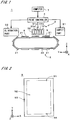
Fig. 1 is a view showing a constitution of aninkjet printer 1 in accordance with a first embodiment of the present invention. Theinkjet printer 1 is a sheet-fed printing apparatus for sequentially performing inkjet color printing on a plurality ofprint mediums 9. - As shown in
Fig. 1 , theinkjet printer 1 has amoving mechanism 2 for moving the plurality ofprint mediums 9 in the (+Y) direction inFig. 1 , anejection part 3 for ejecting fine droplets of ink toward aprint medium 9 in the course of conveyance by themoving mechanism 2, asupply part 51 for supplying theprint mediums 9 to themoving mechanism 2, anelimination part 52 for receiving theprint mediums 9 after completion of printing from themoving mechanism 2, and aprint controller 4 for controlling these mechanism. - The
moving mechanism 2 has a plurality ofstages 21 each of which is for holding one sheet-like print medium 9 (in the present embodiment, the print paper) by suction, a loop-like guide 22 for guiding the plurality ofstages 21, and a belt driving mechanism (not shown) for moving a belt inside theguide 22 in a counterclockwise direction inFig. 1 to move thestages 21 holding theprint mediums 9 in the (+Y) direction at the lower side (i.e., the (-Z) side) of theejection part 3. - The
ejection part 3 has fiveejection mechanisms 31a to 31d, 32 each of which is for ejecting fine droplets of ink from a plurality of outlets, and theejection mechanisms 31a to 31d, 32 are arranged in the Y direction inFig. 1 . In theejection part 3, theejection mechanism 31a lying on the outermost (-Y) side inFig. 1 ejects K (black) colored ink, theejection mechanism 31b at the (+Y) side of theejection mechanism 31a ejects C (cyan) colored ink, theejection mechanism 31c at the (+Y) side of theejection mechanism 31b ejects M (magenta) colored ink, theejection mechanism 31d at the (+Y) side of theejection mechanism 31c ejects Y (yellow) colored ink. In addition, in theejection part 3, theejection mechanism 32 lying on the outermost (+Y) side inFig. 1 ejects clear ink. In the present embodiment, invisible ink which is made visible by irradiation of ultraviolet (i.e., ultraviolet visible ink) is utilized as the clear ink. - In the
inkjet printer 1, with respect to the X direction orthogonal to the moving direction (the Y direction) of theprint medium 9, eachejection mechanism 31a to 31d, 32 in theejection part 3 is provided across the entire width of the print medium 9 (i.e., across the entire length in the X direction), and theejection mechanism 31a to 31d, 32 passes each position on theprint medium 9 once by one-time relative movement of theprint medium 9 toward the (+Y) direction, to complete printing for theprint medium 9. In other words, printing without shuttle movement of theprint medium 9 in the X direction (so-called one-pass printing) is performed in theinkjet printer 1. - A
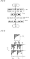
computer 7 is connected to theinkjet printer 1, and original image data and threshold matrices (also called as SPM (Screen Pattern Memory) data) for formation of halftone screen are sent from thecomputer 7 to theprint controller 4 in theinkjet printer 1. The original image data includes data of grayscale colored image to be formed on a coloredimage print area 92 which is set on a main surface 91 (hereinafter, referred to as the "firstmain surface 91") on the (+Z) side of theprint medium 9 shown inFig. 2 and data of grayscale code image to be formed on ablank area 93 around the coloredimage print area 92. The code image is an invisible (or hardly visible) image with naked eye in the state where ambient light is irradiated, it is also an image to become visible under a particular circumstance (in the present embodiment, the circumstance where ultraviolet light is irradiated), and it is also called as the invisible image. For example, a corporate logo relating to theprint medium 9 or a serial number to specify information relating to manufacture of theprint medium 9 is formed as the code image. -
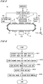
Fig. 3 is a flowchart showing an operation flow of printing by theinkjet printer 1. In theinkjet printer 1, halftone image signal representing the colored image (the signal is hereinafter referred to as the "first halftone image data") and halftone image signal representing the code image (the signal is hereinafter referred to as the "second halftone image data") are generated by the print controller 4 (seeFig. 1 ) on the basis of the original image data and the threshold matrices (Step S11). The first halftone image data has halftone image data of each color K, C, M, Y which is generated by color-separating data of colored image included in the original image into respective colors K, C, M, Y and by halftoning the color-separated image data with the threshold matrices. - In halftoning of the original image (i.e., in generation of halftone image representing the original image), as shown in
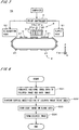
Fig. 4 , theoriginal image 70 is divided into a large number of areas having the fixed size to setrepeat areas 71 each of which serves as a unit in halftoning. The SPM (Screen Pattern Memory) in theprint controller 4 has a matrix space (matrix area) which is a memory area corresponding to onerepeat area 71 and a threshold value is set to each address of the matrix space (i.e., coordinates (pixel) in the matrix space corresponding to each pixel in the repeat area 71) to generate thethreshold matrix 710. - Conceptually, each
repeat area 71 of theoriginal image 70 and thethreshold matrix 710 are superposed and a gray level of each pixel in therepeat area 71 is compared with a correspondent threshold value in thethreshold matrix 710, to thereby determine whether or not formation should be performed (i.e., whether or not a droplet of ink should be ejected) on the position of the pixel on theprint medium 9 which is a halftone recording medium. Thus, if gray levels in theoriginal image 70 are uniform, the formation is performed on the pixels of addresses where threshold values less than the gray levels are set in thethreshold matrix 710 and uniform halftone dots are generated in broad perspective. Actually, since theoriginal image 70 has gradation (i.e., portions having various gray levels), the state of halftone dots varies in therepeat area 71 in accordance with the gradation in theoriginal image 70. - Subsequently, the
print medium 9 shown inFig. 1 is supplied from thesupply part 51 onto astage 21 to be held thereon. Then the movingmechanism 2 and theejection mechanisms 31a to 31d, 32 in theejection part 3 are controlled on the basis of the first halftone image data, and therefore colored ink of K, C, M, Y is ejected toward the colored image print area 92 (seeFig. 2 ) on the firstmain surface 91 of theprint medium 9 moving in the (+Y) direction to form the colored image (Step S12), and the clear ink is ejected onto each dot of the colored image (i.e., each droplet of colored ink applied on the print medium 9) to coat the colored image with the clear ink (to perform so-called overcoating) (Step S13). In theinkjet printer 1, forming of the colored image (Step S12) and coating of the colored image (Step S13) are sequentially performed for each portion of theprint medium 9 in the Y direction, and therefore, for thewhole print medium 9, forming of the colored image (Step S12) and coating of the colored image (Step S13) are performed almost in parallel (the same applies to after-mentioned Step S22 and Step S23 inFig. 6 ). - In Step S13, each dot of the colored image is coated with a dot of clear ink having the same size. In a highlight part of the colored image, the dots of the colored image may be coated with dots of the clear ink having larger size than the dots of the colored image. Therefore, if a landing position of the clear ink (i.e., the position where a droplet of the clear ink is applied) is slightly off from a dot of the colored image, the dot of the colored image is certainly coated with the clear ink. In a tint part of the colored image, there may be a case where the tint part is uniformly coated with the clear ink over the whole surface with no space, and ejection of the clear ink is controlled so that a total area of dots of the clear ink which is applied onto the tint part becomes a predetermined percent of an area of the tint part (the percent is a predetermined percent more than 0% and less than 100%, for example 50%), to apply the clear ink onto the tint part uniformly. Since the total area of dots of the clear ink is made less than the area of the tint part, drying of the colored ink in the tint part is promoted.
- In the
inkjet printer 1, since theejection mechanism 32 is controlled on the basis of not only the first halftone image data but also the second halftone image data, the clear ink is ejected toward theblank area 93 on the firstmain surface 91 of the print medium 9 (in the present embodiment, toward a portion of theblank area 93 lying on the (+X) side or (-X) side of the colored image print area 92) in parallel with coating the colored image with the clear ink in Step S13, to thereby form the code image on theblank area 93 with the clear ink (Step S14). Therefore, on the firstmain surface 91 of theprint medium 9 where the colored image is formed, the coating of the colored image and forming of the code image for theblank area 93 around the colored image (i.e., formation of the code image performed with avoiding the colored image) are performed in parallel, with the identical clear ink ejected from the oneejection mechanism 32. - And the
ejection mechanisms 31a to 31d, 32 pass each position on theprint medium 9 once by one-time relative movement of theprint medium 9 to theejection part 3 in the (+Y) direction, to complete forming the colored image with the colored ink, coating the colored image with the clear ink and forming the code image with the clear ink. After that, theprint medium 9 is withdrawn by theelimination part 52. In theprint medium 9 where printing by theinkjet printer 1 is completed, the colored image on the coloredimage print area 92 is coated with the clear ink and wear resistance of the colored image is improved. In addition, since the code image is formed, strict copying or forging of theprint medium 9 printed with the colored image (i.e., strict copying or forging of the colored image and the code image) becomes difficult. As the result, theoriginal print medium 9 is easily distinguished from a copy of theprint medium 9 or the like, and security of the colored image on theprint medium 9 is improved. In theinkjet printer 1, the above-mentioned printing is sequentially performed for a plurality of print media 9 (the same applies to the following other embodiments). - As described above, in the
inkjet printer 1, on the firstmain surface 91 of theprint medium 9 where the colored image is formed, the coating of the colored image and the forming of the code image are performed with the same clear ink ejected from the oneejection mechanism 32. Therefore, structure of theinkjet printer 1 is simplified, and improvement of wear resistance and improvement of security of the colored image can be achieved while reducing manufacturing cost of the apparatus. In addition, printing cost for theprint medium 9 can be reduced. - In the
inkjet printer 1, since the ultraviolet visible ink is utilized as the clear ink, readout of the code image on theprint medium 9 can be easily performed with use of relatively inexpensive and easy-to-use black light or the like, and without using an expensive instrument, equipment or the like. Furthermore, since the code image is made grayscale, inability to detect the code image due to a short ejection amount of the clear ink or exposure of the code image under normal illumination due to an excessive ejection amount of the clear ink is prevented and forming code information with high accuracy is achieved. - In the
inkjet printer 1, since the code image is formed with avoiding the colored image, outlets used for the forming of the code image are made different from outlets used for the coating of the colored image in theejection mechanism 32. Therefore, ejection control of the clear ink from the outlets in theejection mechanism 32 which are used for the coating of the colored image is performed on the basis of only the first halftone image data, and ejection control of the clear ink from the outlets which are used for the forming of the code image is performed on the basis of only the second halftone image data. As the result, control of theejection mechanism 32 is simplified. In addition, since the code image is formed on theblank area 93 around the colored image, the coating of the colored image and the forming of the code image can be easily performed in parallel. As the result, the printing for theprint medium 9 can be performed quickly. - As above, in the
inkjet printer 1, since coating the colored image and forming the code image with the clear ink are performed by one-pass printing, structure of the movingmechanism 2 for moving theprint medium 9 relative to theejection part 3 can be simplified and the printing for theprint medium 9 can be performed more quickly. - In the meantime, if forming the colored image for the
print medium 9 is performed in an apparatus different from theinkjet printer 1, it is necessary to perform adjustment of relative position between the colored image on theprint medium 9 and theejection mechanism 32 by scanning the colored image with a scanner or the like before ejection of the clear ink for theprint medium 9 in theinkjet printer 1. Correspondingly, in theinkjet printer 1 in accordance with the present embodiment, the movingmechanism 2 used for the coating of the colored image and the forming of the code image is controlled together with theejection mechanisms 31a to 31d of theejection part 3 by theprint controller 4, to perform forming the colored image on theprint medium 9. Therefore, adjustment of relative position between the colored image and theejection mechanism 32 as described above is made unnecessary, and the coating of the colored image and the forming of the code image are simplified. Furthermore, since the forming of the colored image is performed by the same inkjet method as that for the coating of the colored image and the forming of the code image, structure of theejection part 3 can be simplified. In addition to that, since the forming of the colored image is performed almost in parallel with the coating of the colored image and the forming of the code image (in more detail, while preceding them slightly, almost in parallel with them), the printing for theprint medium 9 is performed more quickly. - In the above embodiment, it is described that the code image is formed on the
blank area 93 around the colored image on the firstmain surface 91 of theprint medium 9 shown inFig. 2 . However, in theinkjet printer 1, a code image may be formed on the colored image formed on the coloredimage print area 92. When forming the code image on the colored image, for example in Steps S13, S14, ejection amounts of the clear ink from a group of outlets, which is opposed to the coloredimage print area 92, in theejection mechanism 32 are set at a predetermined amount so as to uniformly coat the whole coloredimage print area 92 with the clear ink with no space, and furthermore, control to increase the ejection amount of the clear ink from an outlet, which corresponds to each dot of the code image, by approximately 20% to 30% of the above predetermined amount is performed by theprint controller 4 on the basis of the second halftone image data. - Therefore, the colored
image print area 92 where the colored image is formed is coated with the clear ink over the whole surface, and heights of portions, corresponding to the code image, in the coating layer of the clear ink are made higher than that of the surround. As above, since the code image is formed on the colored image, visual recognition of the code image can be made more difficult in the state where ambient light is irradiated. The code image may be formed on both the colored image and theblank area 93. - Next, discussion will be made on an inkjet printer in accordance with a second embodiment of the present invention.
Fig. 5 is a view showing a constitution of the inkjet printer 1a in accordance with the second embodiment. The constituents of the inkjet printer 1a are same as those of theinkjet printer 1 shown inFig. 1 except for the point where the movingmechanism 2 has areversal mechanism 24 at the lower side of theguide 22, and in the following description, constituents corresponding to respective constituents of theinkjet printer 1 are denoted by the same reference signs. -
Fig. 6 is a flowchart showing an operation flow of printing by the inkjet printer 1a. In the inkjet printer 1a, the first halftone image data representing the colored image and the second halftone image data representing the code image are generated in theprint controller 4 in the same manner as the first embodiment (Step S21). Subsequently, theprint medium 9 is supplied from thesupply part 51 onto astage 21 to be held thereon, and the movingmechanism 2 and theejection mechanisms 31a to 31d, 32 in theejection part 3 are controlled by theprint controller 4, thereby to form the colored image on the colored image print area 92 (seeFig. 2 ) of the firstmain surface 91 of the print medium 9 (Step S22) and to perform coating the colored image with the clear ink (Step S23). - The
print medium 9 where the forming of the colored image and the coating of the colored image are completed moves in a counterclockwise direction inFig. 5 by movement of the belt inside theguide 22 of the movingmechanism 2, and it reaches at thereversal mechanism 24 without being withdrawn by theelimination part 52. Theprint medium 9 is reversed by thereversal mechanism 24, and the firstmain surface 91 which is one main surface on which the colored image has been formed is held on thestage 21 by suction (Step S24). - After that, since the belt inside the
guide 22 further moves, theprint medium 9 moves in the counterclockwise direction to lie at the lower side of theejection part 3 and a second main surface 94 (seeFig. 2 ) of theprint medium 9 which is the other main surface is opposite to theejection mechanism 32. In the inkjet printer 1a, the movingmechanism 2 and theejection mechanism 32 are controlled by theprint controller 4, and therefore ejection of the clear ink toward the secondmain surface 94 of theprint medium 9 is performed to perform forming of the code image on the second main surface 94 (Step S25). Theprint medium 9 where the forming of the code image is completed is withdrawn by theelimination part 52. - In the
print medium 9, wear resistance of the colored image is improved by coating the colored image with the clear ink, and security of the colored image on theprint medium 9 is improved by forming the code image in a similar fashion to the first embodiment. In the inkjet printer 1a, the coating of the colored image and the forming of the code image are performed with the same clear ink ejected from the oneejection mechanism 32 in a similar fashion to theinkjet printer 1. Therefore, improvement of wear resistance and improvement of security of the colored image can be achieved while reducing manufacturing cost of the apparatus without complicating structure of the inkjet printer 1a. In addition, printing cost for theprint medium 9 can be reduced. - In the inkjet printer 1a, the code image is formed on the second
main surface 94 which is different from the firstmain surface 91 on which the colored image is formed. Thus, when controlling ejection of the clear ink from theejection mechanism 32, it becomes unnecessary to merge the first halftone image data with the second halftone image data. Consequently, control of theejection mechanism 32 is simplified. - In the inkjet printer 1a, there may be a case where forming the code image for the second
main surface 94 is first performed, and then forming the colored image and coating the colored image for the firstmain surface 91 are performed. In addition to forming the code image on the secondmain surface 94, forming code image may be performed on theblank area 93 of the firstmain surface 91 or on the colored image. - Next, discussion will be made on an inkjet printer in accordance with a third embodiment of the present invention.
Fig. 7 is a view showing a constitution of the inkjet printer 1b in accordance with the third embodiment. The constituents of the inkjet printer 1b are same as those of theinkjet printer 1 shown inFig. 1 except for the point where in theejection part 3, theejection mechanism 32 for ejecting the clear ink is located at the (-Y) side of theejection mechanism 31a to 31d for ejecting the colored ink K, and in the following description, constituents corresponding to respective constituents of theinkjet printer 1 are denoted by the same reference signs. - In the inkjet printer 1b, the clear ink is uniformly ejected on the
print medium 9 before forming of the colored image, and therefore modifying a surface of theprint medium 9 to be printed with the colored image is performed (so-called undercoating is performed). Hereinafter, discussion will be made on an operation flow of printing by the inkjet printer 1b with reference toFig. 8 . In the inkjet printer 1b, the first halftone image data representing the colored image and the second halftone image data representing the code image are generated in theprint controller 4 in the same manner as the first embodiment (Step S31). - Subsequently, the
print medium 9 is supplied from thesupply part 51 onto astage 21 to be held thereon, and the movingmechanism 2 and theejection mechanism 32 in theejection part 3 are controlled byprint controller 4. Therefore, the clear ink is uniformly ejected from outlets, which are opposed to the colored image print area 92 (seeFig. 2 ) of theprint medium 9 on which the colored image is to be formed, out of the plurality of outlets in theejection mechanism 32 toward the coloredimage print area 92, to perform surface modification of the coloredimage print area 92 on the first main surface 91 (seeFig. 2 ) of the print medium 9 (Step S32). In addition, ejection of the clear ink from outlets, which are opposed to the blank area 93 (seeFig. 2 ) around the coloredimage print area 92, out of the plurality of outlets in theejection mechanism 32, is controlled on the basis of the second halftone image data, to thereby form the code image on the blank area 93 (i.e., with avoiding the colored image print area 92) in parallel with Step S32 (Step S33). - In the inkjet printer 1b, since the moving
mechanism 2 and theejection mechanisms 31a to 31d of theejection part 3 are controlled by theprint controller 4, the colored ink is ejected toward portions of the colored image print area 92 (i.e., the coloredimage print area 92 after the surface modification) having passed under theejection mechanism 32, to perform forming of the colored image (Step S34). In the inkjet printer 1b, modifying the surface and forming the code image (Step S32, S33), and forming the colored image (Step S34) are sequentially performed on each portion of theprint medium 9 in the Y direction, and therefore for thewhole print medium 9, modifying the surface and forming the code image (Step S32, S33), and forming the colored image (Step S34) are performed in almost parallel. - In the inkjet printer 1b, the
ejection mechanisms print medium 9 once by one-time relative movement of theprint medium 9 to theejection part 3 toward the (+Y) direction, to complete the surface modification of theprint medium 9 with the clear ink, the forming of the code image with the clear ink and the forming of the colored image with the colored ink. After that, theprint medium 9 is withdrawn by theelimination part 52. - In the
print medium 9 where printing by the inkjet printer 1b is completed, since the surface modification with the clear ink is performed on the coloredimage print area 92 before forming the colored image, the surface of the coloredimage print area 92 becomes the suitable condition for the colored ink used for the forming of the colored image. As the result, forming high accuracy and high quality colored image on the coloredimage print area 92 is achieved. In addition, since the code image is formed on theprint medium 9, copying or forging of theprint medium 9 printed with the colored image becomes difficult and security of the colored image on theprint medium 9 is increased. - In the inkjet printer 1b, the surface modification of the
print medium 9 and the forming of the code image are performed with the same clear ink ejected from the oneejection mechanism 32. Therefore, the surface modification of theprint medium 9, the forming of high accuracy and high quality colored image by the modification, and improvement of security of the colored image on theprint medium 9 can be achieved while reducing manufacturing cost of the apparatus without complicating structure of the inkjet printer 1b. In addition, printing cost for theprint medium 9 can be reduced. - As described above, in the inkjet printer 1b, the code image is formed on the
blank area 93 around the colored image, the surface modification of theprint medium 9 can be easily performed in parallel with the forming of the code image. Therefore, the printing for theprint medium 9 can be performed quickly. In the inkjet printer 1b, the surface modification with the clear ink may be also performed on theblank area 93. In this case, for example, ejection amounts of the clear ink from a group of outlets, which is opposed to theblank area 93, in theejection mechanism 32 are set at a predetermined amount so as to uniformly eject the clear ink on theblank area 93, and furthermore, control to increase the ejection amount of the clear ink from an outlet, which corresponds to each dot of the code image, by approximately 20% to 30% of the above predetermined amount is performed by theprint controller 4 on the basis of the second halftone image data. - In the inkjet printer 1b, since the ultraviolet visible ink is utilized as the clear ink, readout of the code image on the
print medium 9 can be easily performed in the same manner as the first embodiment. In addition, since the code image is made grayscale, forming code information with high accuracy is achieved. - In the meantime, if forming the colored image for the
print medium 9 is performed in an apparatus different from the inkjet printer 1b, it is necessary to obtain positional information of the coloredimage print area 92 on theprint medium 9 and to adjust relative position between the ejection mechanism in the apparatus used for forming the colored image and the coloredimage print area 92 before the forming of the colored image. Correspondingly, in the inkjet printer 1b in accordance with the present embodiment, the movingmechanism 2 used for the surface modification of theprint medium 9 and the forming of the code image is controlled together with theejection mechanisms 31a to 31d in theejection part 3 by theprint controller 4, to perform the forming of the colored image on theprint medium 9. Therefore, adjustment of relative position between the coloredimage print area 92 and the ejection mechanism in the apparatus used for forming the colored image as described above is made unnecessary, and the forming of the colored image is simplified. Furthermore, since the forming of the colored image is performed by the same inkjet method as that for the surface modification of theprint medium 9 and the forming of the code image, structure of theejection part 3 can be simplified. In addition to that, since the forming of the colored image is performed almost in parallel with the surface modification of theprint medium 9 and the forming of the code image, the printing for theprint medium 9 is performed more quickly. - Next, discussion will be made on an inkjet printer in accordance with a fourth embodiment of the present invention.
Fig. 9 is a view showing a constitution of the inkjet printer 1c in accordance with the fourth embodiment. The constituents of the inkjet printer 1c are same as those of the inkjet printer 1b shown inFig. 7 except for the points where thesame reversal mechanism 24 as that in the inkjet printer 1a (seeFig. 5 ) in accordance with the second embodiment is provided under theguide 22 and the code image is formed on the second main surface 94 (seeFig. 2 ) of theprint medium 9. In the following description, constituents corresponding to respective constituents of the inkjet printer 1b are denoted by the same reference signs. - As shown in
Fig. 10 , in the inkjet printer 1c, the first halftone image data representing the colored image and the second halftone image data representing the code image are generated in the print controller 4 (Step S41). Subsequently, theprint medium 9 is supplied from thesupply part 51 onto astage 21 to be held thereon, and the movingmechanism 2 and theejection mechanisms ejection part 3 are controlled byprint controller 4. Therefore, the clear ink is uniformly ejected toward the colored image print area 92 (seeFig. 2 ) of theprint medium 9 to perform surface modification of the coloredimage print area 92, and the colored image is formed on the coloredimage print area 92 after the surface modification (Step S42, S43). - The
print medium 9 where the surface modification and the forming of the colored image are completed reaches at thereversal mechanism 24 without being withdrawn by theelimination part 52, and it is reversed by the reversal mechanism 24 (Step S44). After that, theprint medium 9 moves to the lower side of theejection part 3 and the movingmechanism 2 and theejection mechanism 32 are controlled by theprint controller 4 to perform forming of the code image on the secondmain surface 94 of the print medium 9 (Step S45). Theprint medium 9 where the forming of the code image is completed is withdrawn by theelimination part 52. - In the inkjet printer 1c, the surface modification of the
print medium 9 and the forming of the code image are performed with the same clear ink ejected from the oneejection mechanism 32. Therefore, the surface modification of theprint medium 9 and the forming of high accuracy and high quality colored image by the modification, and improvement of security of the colored image on theprint medium 9 can be achieved while reducing manufacturing cost of the apparatus without complicating structure of the inkjet printer 1c in a similar fashion to the third embodiment. In addition, printing cost for theprint medium 9 can be reduced. Furthermore, control of theejection mechanism 32 is simplified since the code image is formed on the secondmain surface 94. - Next, discussion will be made on an inkjet printer in accordance with a fifth embodiment of the present invention.
Fig. 11 is a view showing a constitution of aprinter system 100 having the inkjet printer 1d in accordance with the fifth embodiment. As shown inFig. 11 , theprinter system 100 has an offsetprinting apparatus 101 and ascanner 102 in addition to the inkjet printer 1d. The constituents of the inkjet printer 1d are same as those of theinkjet printer 1 shown inFig. 1 except for the points where theejection mechanism 31a to 31d for ejecting the colored ink are not provided in theejection part 3. In the following description, constituents corresponding to respective constituents of theinkjet printer 1 are denoted by the same reference signs. - In the
printer system 100, the colored image is printed on the colored image print area 92 (seeFig. 2 ) of theprint medium 9 by the offsetprinting apparatus 101, and the first main surface 91 (seeFig. 2 ) of theprint medium 9 printed with the colored image is scanned by thescanner 102. In the inkjet printer 1d, on the basis of information indicating dot positions of the colored ink in the coloredimage print area 92 and a position of the blank area 93 (seeFig. 2 ) which are obtained from output of thescanner 102, the movingmechanism 2 and the ejection mechanism 32 (seeFig. 1 ) in theejection part 3 are controlled by theprint controller 4, to coat the colored image on the coloredimage print area 92 with the clear ink and to form the code image with the clear ink on theblank area 93. - In the inkjet printer 1d of the
printer system 100, on the firstmain surface 91 of theprint medium 9 where the colored image has been formed, the coating of the colored image and the forming of the code image are performed with the same clear ink ejected from the oneejection mechanism 32 in a similar fashion to the first embodiment. Therefore, improvement of wear resistance and improvement of security of the colored image can be achieved while reducing manufacturing cost of the apparatus without complicating structure of the inkjet printer 1d. - In the
printer system 100, if print information of the colored image in the offset printing apparatus 101 (i.e., the information indicating dot positions of the colored ink) and information indicating a position of theblank area 93 on theprint medium 9 are obtained in advance, thescanner 102 may be omitted. Also another printing apparatus such as an electrophotographic printer may be provided as substitute for the offsetprinting apparatus 101. - In the inkjet printer 1d, if the whole area of the colored
image print area 92 is uniformly coated with the clear ink or the like, approximate positions of the coloredimage print area 92 and theblank area 93 have only to be detectable. Thus, as long as a guide for performing alignment of theprint medium 9 by contacting edges of theprint medium 9 or the like is provided in eachstage 21 of the inkjet printer 1d, thescanner 102 can be omitted from theprinter system 100. - Though the preferred embodiments of the present invention have been discussed above, the present invention is not limited to the above-discussed preferred embodiments, but allows various variations.
- In the inkjet printers in accordance with the third and fourth embodiments, there may be a case where an ejection mechanism for ejecting the clear ink is provided also at the (+Y) side of the
ejection mechanism 31d in theejection part 3 and coating the colored image with the clear ink is performed as appropriate. - The inkjet printers in accordance with the first to fourth embodiments may be utilized as a monochrome printer by omitting the
ejection mechanism 31b to 31d from theejection part 3. The code image may be formed by not multi-level dots (i.e., dots having a plurality of sizes) of the clear ink but one sized dots. - In the inkjet printers in accordance with the above-discussed embodiments, there may be a case where a width of each ejection head in the
ejection part 3 in the X direction is made less than the width of theprint medium 9 in the X direction, shuttle movement of theejection part 3 in the X direction and movement of theprint medium 9 toward the (+Y) direction are performed in parallel, and therefore printing for theprint medium 9 is performed. The movingmechanism 2 do not always have to be a mechanism for moving theprint medium 9, for example, it may be a mechanism for moving the ejection part 3 (i.e., theejection mechanisms 31a to 31d, 32) to move theprint medium 9 relative to theejection part 3. - In the above-discussed inkjet printers, for example, printing may be performed for a web which is continuous paper. In the inkjet printer, printing is not necessarily performed on the sheet-
like print medium 9 such as paper or film, and printing may be performed on print media in various forms such as a thin plate-like print medium or others. - While the invention has been shown and described in detail, the foregoing description is in all aspects illustrative and not restrictive. It is therefore understood that numerous modifications and variations can be devised without departing from the scope of the invention, which is limited only by the appended claims.
-
- 1, 1a to 1d inkjet printer
- 2 moving mechanism
- 4 print controller
- 9 print medium
- 32 ejection mechanism
- 91 first main surface
- 92 colored image print area
- 93 blank area
- 94 second main surface
- S11 to S14, S21 to S25, S31 to S34, S41 to S45 step
Claims (7)
- An inkjet printer (1), comprising:an ejection mechanism (32) for ejecting fine droplets of clear ink from a plurality of outlets; anda moving mechanism (2) for moving a print medium (9) relative to said ejection mechanism; characterized bya print controller (4) which controls said ejection mechanism and said moving mechanism, to coat a colored image on said print medium with said clear ink and to form a code image on the coated area corresponding to_said colored image with said clear ink on the basis of second halftone image data, said colored image being formed on the basis of first halftone image data,wherein said ejection mechanism passes each position on said print medium once by one-time relative movement thereof to complete coating said colored image with said clear ink and forming said code image with said clear ink, andwherein the coating of said colored image and the forming of said code image are performed in parallel.
- The inkjet printer according to claim 1,
wherein said print controller sets ejection amounts of said clear ink from said outlets of said ejection mechanism at a predetermined amount so as to uniformly coat the whole colored image with said clear ink with no space, and increases the ejection amounts of said clear ink from some outlets of said ejection mechanism by approximately 20% to 30% of said predetermined amount, said some outlets corresponding to each dot of said code image. - The inkjet printer according to claim 1 or 2, wherein
said clear ink is ultraviolet visible ink. - The inkjet printer according to any one of claims 1 to 3, further comprising
another ejection mechanism (31a to 31d) for ejecting fine droplets of colored ink from a plurality of outlets; wherein
said another ejection mechanism is controlled together with said moving mechanism by said print controller, to form said colored image on said print medium. - An inkjet printing method, comprising the step of:a) ejecting fine droplets of clear ink from a plurality of outlets in an ejection mechanism (32) and moving a print medium (9) relative to said ejection mechanism, to coat a colored image on said print medium with said clear ink, said colored image being formed on the basis of first halftone image data; characterized by the step ofb) ejecting fine droplets of said clear ink from said plurality of outlets and moving said print medium relative to said ejection mechanism, to form a code image on the coated area corresponding to_said colored image with said clear ink on the basis of second halftone image data,wherein said ejection mechanism passes each position on said print medium once by one-time relative movement thereof to complete coating said colored image with said clear ink and forming said code image with said clear ink, and
wherein the coating of said colored image and the forming of said code image are performed in parallel. - The inkjet printing method according to claim 5,
wherein ejection amounts of said clear ink from said outlets of said ejection mechanism are set at a predetermined amount_so as to uniformly coat the whole colored image with said clear ink with no space, and the ejection amounts of said clear ink from some outlets of said ejection mechanism are increased by approximately 20% to 30% of said predetermined amount, said some outlets corresponding to each dot of said code image. - The inkjet printing method according to claim 5 or 6, wherein
said clear ink is ultraviolet visible ink.
Applications Claiming Priority (2)
| Application Number | Priority Date | Filing Date | Title |
|---|---|---|---|
| JP2009067668A JP5129771B2 (en) | 2009-03-19 | 2009-03-19 | Inkjet printer and inkjet printing method |
| PCT/JP2010/053503 WO2010106918A1 (en) | 2009-03-19 | 2010-03-04 | Inkjet printer and inkjet printing method |
Publications (3)
| Publication Number | Publication Date |
|---|---|
| EP2409841A1 EP2409841A1 (en) | 2012-01-25 |
| EP2409841A4 EP2409841A4 (en) | 2014-05-14 |
| EP2409841B1 true EP2409841B1 (en) | 2018-06-13 |
Family
ID=42739581
Family Applications (1)
| Application Number | Title | Priority Date | Filing Date |
|---|---|---|---|
| EP10753413.3A Not-in-force EP2409841B1 (en) | 2009-03-19 | 2010-03-04 | Inkjet printer and inkjet printing method |
Country Status (4)
| Country | Link |
|---|---|
| US (1) | US20110222126A1 (en) |
| EP (1) | EP2409841B1 (en) |
| JP (1) | JP5129771B2 (en) |
| WO (1) | WO2010106918A1 (en) |
Families Citing this family (21)
| Publication number | Priority date | Publication date | Assignee | Title |
|---|---|---|---|---|
| JP4950977B2 (en) * | 2008-10-08 | 2012-06-13 | キヤノン株式会社 | Image forming apparatus |
| JP5464913B2 (en) * | 2009-06-01 | 2014-04-09 | キヤノン株式会社 | Image forming apparatus, information processing apparatus, control method for image forming apparatus, control method for information processing apparatus, and program |
| JP5539117B2 (en) * | 2010-08-31 | 2014-07-02 | キヤノン株式会社 | Inkjet recording apparatus and inkjet recording method |
| US8608272B2 (en) * | 2010-12-03 | 2013-12-17 | Xerox Corporation | System and method for inkjet printing with a differential halftoned protective overcoat with gloss compensation |
| JP5652253B2 (en) * | 2011-02-24 | 2015-01-14 | セイコーエプソン株式会社 | Liquid ejection device |
| JP5838564B2 (en) * | 2011-02-24 | 2016-01-06 | セイコーエプソン株式会社 | Liquid ejection device |
| JP5802037B2 (en) * | 2011-03-29 | 2015-10-28 | 株式会社Screenホールディングス | Image recording method |
| JP2012218233A (en) * | 2011-04-06 | 2012-11-12 | Seiko Epson Corp | Liquid ejection device and control method therefor |
| JP5811589B2 (en) * | 2011-05-18 | 2015-11-11 | セイコーエプソン株式会社 | Printing apparatus and printing method |
| JP5955088B2 (en) * | 2012-05-08 | 2016-07-20 | キヤノン株式会社 | Image processing apparatus and image processing method |
| US9352561B2 (en) | 2012-12-27 | 2016-05-31 | Kateeva, Inc. | Techniques for print ink droplet measurement and control to deposit fluids within precise tolerances |
| US11673155B2 (en) | 2012-12-27 | 2023-06-13 | Kateeva, Inc. | Techniques for arrayed printing of a permanent layer with improved speed and accuracy |
| US9832428B2 (en) | 2012-12-27 | 2017-11-28 | Kateeva, Inc. | Fast measurement of droplet parameters in industrial printing system |
| US11141752B2 (en) | 2012-12-27 | 2021-10-12 | Kateeva, Inc. | Techniques for arrayed printing of a permanent layer with improved speed and accuracy |
| US9700908B2 (en) | 2012-12-27 | 2017-07-11 | Kateeva, Inc. | Techniques for arrayed printing of a permanent layer with improved speed and accuracy |
| JP5936294B2 (en) | 2012-12-27 | 2016-06-22 | カティーバ, インコーポレイテッド | Techniques for controlling the amount of printing ink that deposits fluid within close tolerances |
| KR102495563B1 (en) | 2013-12-12 | 2023-02-06 | 카티바, 인크. | Ink-based layer fabrication using halftoning to control thickness |
| DE102015218325A1 (en) * | 2015-09-24 | 2017-03-30 | Bhs Corrugated Maschinen- Und Anlagenbau Gmbh | Corrugating machine |
| US9956789B2 (en) * | 2015-10-07 | 2018-05-01 | Xerox Corporation | Systems and methods for implementing a post-processing scheme for minimizing curl in sets of output image receiving media substrates imaged in image forming devices |
| US9747532B1 (en) | 2016-07-18 | 2017-08-29 | Ricoh Company, Ltd. | Multi-level protector coat bitmap generation for printing systems |
| CN106393967A (en) * | 2016-08-29 | 2017-02-15 | 浙江新长海新材料股份有限公司 | Automatic code imprinting machine of packaging bags |
Family Cites Families (13)
| Publication number | Priority date | Publication date | Assignee | Title |
|---|---|---|---|---|
| JP3224491B2 (en) * | 1995-06-01 | 2001-10-29 | キヤノン株式会社 | Image processing apparatus and method |
| JPH09174823A (en) * | 1995-12-27 | 1997-07-08 | Canon Inc | Ink jet recorder and image forming method |
| JP3774505B2 (en) * | 1996-04-23 | 2006-05-17 | キヤノン株式会社 | Halftone recording apparatus, halftone recording method, ink tank, head cartridge, inkjet recording apparatus, and inkjet recording method |
| JP3347647B2 (en) * | 1997-07-28 | 2002-11-20 | キヤノン株式会社 | Ink jet recording apparatus and ink jet recording method |
| JPH11268457A (en) | 1998-03-23 | 1999-10-05 | Toppan Printing Co Ltd | Method and apparatus for overcoat |
| US7246239B2 (en) * | 2001-01-24 | 2007-07-17 | Digimarc Corporation | Digital watermarks for checking authenticity of printed objects |
| JP3835383B2 (en) * | 2002-09-09 | 2006-10-18 | セイコーエプソン株式会社 | Liquid ejection apparatus and computer system |
| JP2005119013A (en) * | 2003-10-14 | 2005-05-12 | Ricoh Co Ltd | Image forming apparatus |
| JP2006027193A (en) * | 2004-07-21 | 2006-02-02 | Konica Minolta Holdings Inc | Inkjet recording method and device |
| JP2006096005A (en) * | 2004-09-30 | 2006-04-13 | Fuji Photo Film Co Ltd | Card information recording medium and method for manufacturing it |
| EP1705529A1 (en) * | 2005-03-22 | 2006-09-27 | Eastman Kodak Company | Method and device for controlling differential gloss and print item produced thereby |
| JP2007021925A (en) * | 2005-07-19 | 2007-02-01 | Seiko Epson Corp | Inkjet recording method |
| JP2008126628A (en) * | 2006-11-24 | 2008-06-05 | Canon Inc | Inkjet recording device and recording method |
-
2009
- 2009-03-19 JP JP2009067668A patent/JP5129771B2/en not_active Expired - Fee Related
-
2010
- 2010-03-04 WO PCT/JP2010/053503 patent/WO2010106918A1/en active Application Filing
- 2010-03-04 US US13/128,505 patent/US20110222126A1/en not_active Abandoned
- 2010-03-04 EP EP10753413.3A patent/EP2409841B1/en not_active Not-in-force
Non-Patent Citations (1)
| Title |
|---|
| None * |
Also Published As
| Publication number | Publication date |
|---|---|
| US20110222126A1 (en) | 2011-09-15 |
| EP2409841A4 (en) | 2014-05-14 |
| JP2010214928A (en) | 2010-09-30 |
| EP2409841A1 (en) | 2012-01-25 |
| WO2010106918A1 (en) | 2010-09-23 |
| JP5129771B2 (en) | 2013-01-30 |
Similar Documents
| Publication | Publication Date | Title |
|---|---|---|
| EP2409841B1 (en) | Inkjet printer and inkjet printing method | |
| US8605303B2 (en) | Content-aware image quality defect detection in printed documents | |
| US7484821B2 (en) | Method of determining ink ejection method, printing apparatus, and method of manufacturing printing apparatus | |
| JP4822712B2 (en) | Image forming apparatus, image processing method, and program | |
| JP4909321B2 (en) | Image processing method, program, image processing apparatus, image forming apparatus, and image forming system | |
| US8608272B2 (en) | System and method for inkjet printing with a differential halftoned protective overcoat with gloss compensation | |
| US8511788B2 (en) | Image recording method and apparatus | |
| US11778123B2 (en) | Artifact compensation mechanism | |
| US8646862B2 (en) | System and method for detection and compensation of inoperable inkjets in an inkjet printing apparatus | |
| US8967751B2 (en) | Image processing apparatus and image processing method | |
| EP1734736B1 (en) | Compensation for malfunctioning jets | |
| US20230123461A1 (en) | Artifact compensation mechanism | |
| US8864256B2 (en) | Image processing apparatus for processing multivalue image data in an area corresponding to an overlapped portion of nozzle arrays | |
| US8824014B1 (en) | System and method for adjustment of coverage parameters for different colors in image data | |
| US9738066B1 (en) | System and method for image data processing for inoperable inkjet compensation in an inkjet printer | |
| US8960839B1 (en) | System and method for spatial dependent correction for images printed with multiple drop parameters | |
| JP3996857B2 (en) | Inkjet printer and inkjet printing system | |
| US20110193905A1 (en) | Printing device | |
| US6491374B1 (en) | Methods and apparatuses for printing with uniform and non-uniform print mask functions | |
| US9211746B1 (en) | Hybrid printer for printing on non-porous media | |
| US11516361B2 (en) | Image forming apparatus and image forming method | |
| US6211893B1 (en) | Multi-gradation recording method | |
| US20110310154A1 (en) | System And Method For Preserving Edges While Enabling Inkjet Correction Within An Interior Of An Image | |
| JP2005349659A (en) | Method of recording and recorder | |
| JP5816041B2 (en) | Color inkjet printer |
Legal Events
| Date | Code | Title | Description |
|---|---|---|---|
| PUAI | Public reference made under article 153(3) epc to a published international application that has entered the european phase |
Free format text: ORIGINAL CODE: 0009012 |
|
| 17P | Request for examination filed |
Effective date: 20110414 |
|
| AK | Designated contracting states |
Kind code of ref document: A1 Designated state(s): AT BE BG CH CY CZ DE DK EE ES FI FR GB GR HR HU IE IS IT LI LT LU LV MC MK MT NL NO PL PT RO SE SI SK SM TR |
|
| DAX | Request for extension of the european patent (deleted) | ||
| A4 | Supplementary search report drawn up and despatched |
Effective date: 20140416 |
|
| RIC1 | Information provided on ipc code assigned before grant |
Ipc: B41J 2/21 20060101ALI20140410BHEP Ipc: H04N 21/8358 20110101ALI20140410BHEP Ipc: B41J 11/00 20060101ALI20140410BHEP Ipc: B41J 2/01 20060101AFI20140410BHEP Ipc: B41J 29/00 20060101ALI20140410BHEP |
|
| RAP1 | Party data changed (applicant data changed or rights of an application transferred) |
Owner name: SCREEN HOLDINGS CO., LTD. |
|
| STAA | Information on the status of an ep patent application or granted ep patent |
Free format text: STATUS: EXAMINATION IS IN PROGRESS |
|
| 17Q | First examination report despatched |
Effective date: 20170119 |
|
| GRAP | Despatch of communication of intention to grant a patent |
Free format text: ORIGINAL CODE: EPIDOSNIGR1 |
|
| STAA | Information on the status of an ep patent application or granted ep patent |
Free format text: STATUS: GRANT OF PATENT IS INTENDED |
|
| RIC1 | Information provided on ipc code assigned before grant |
Ipc: B41J 11/00 20060101ALI20180214BHEP Ipc: B41M 7/00 20060101ALI20180214BHEP Ipc: H04N 21/8358 20110101ALI20180214BHEP Ipc: B41J 2/01 20060101AFI20180214BHEP Ipc: B41M 5/00 20060101ALI20180214BHEP Ipc: B41J 2/21 20060101ALI20180214BHEP Ipc: B41J 29/00 20060101ALI20180214BHEP |
|
| INTG | Intention to grant announced |
Effective date: 20180301 |
|
| GRAS | Grant fee paid |
Free format text: ORIGINAL CODE: EPIDOSNIGR3 |
|
| GRAA | (expected) grant |
Free format text: ORIGINAL CODE: 0009210 |
|
| STAA | Information on the status of an ep patent application or granted ep patent |
Free format text: STATUS: THE PATENT HAS BEEN GRANTED |
|
| AK | Designated contracting states |
Kind code of ref document: B1 Designated state(s): AT BE BG CH CY CZ DE DK EE ES FI FR GB GR HR HU IE IS IT LI LT LU LV MC MK MT NL NO PL PT RO SE SI SK SM TR |
|
| REG | Reference to a national code |
Ref country code: GB Ref legal event code: FG4D |
|
| REG | Reference to a national code |
Ref country code: CH Ref legal event code: EP Ref country code: AT Ref legal event code: REF Ref document number: 1008067 Country of ref document: AT Kind code of ref document: T Effective date: 20180615 |
|
| REG | Reference to a national code |
Ref country code: IE Ref legal event code: FG4D |
|
| REG | Reference to a national code |
Ref country code: DE Ref legal event code: R096 Ref document number: 602010051276 Country of ref document: DE |
|
| REG | Reference to a national code |
Ref country code: NL Ref legal event code: MP Effective date: 20180613 |
|
| REG | Reference to a national code |
Ref country code: LT Ref legal event code: MG4D |
|
| PG25 | Lapsed in a contracting state [announced via postgrant information from national office to epo] |
Ref country code: CY Free format text: LAPSE BECAUSE OF FAILURE TO SUBMIT A TRANSLATION OF THE DESCRIPTION OR TO PAY THE FEE WITHIN THE PRESCRIBED TIME-LIMIT Effective date: 20180613 Ref country code: LT Free format text: LAPSE BECAUSE OF FAILURE TO SUBMIT A TRANSLATION OF THE DESCRIPTION OR TO PAY THE FEE WITHIN THE PRESCRIBED TIME-LIMIT Effective date: 20180613 Ref country code: SE Free format text: LAPSE BECAUSE OF FAILURE TO SUBMIT A TRANSLATION OF THE DESCRIPTION OR TO PAY THE FEE WITHIN THE PRESCRIBED TIME-LIMIT Effective date: 20180613 Ref country code: ES Free format text: LAPSE BECAUSE OF FAILURE TO SUBMIT A TRANSLATION OF THE DESCRIPTION OR TO PAY THE FEE WITHIN THE PRESCRIBED TIME-LIMIT Effective date: 20180613 Ref country code: NO Free format text: LAPSE BECAUSE OF FAILURE TO SUBMIT A TRANSLATION OF THE DESCRIPTION OR TO PAY THE FEE WITHIN THE PRESCRIBED TIME-LIMIT Effective date: 20180913 Ref country code: BG Free format text: LAPSE BECAUSE OF FAILURE TO SUBMIT A TRANSLATION OF THE DESCRIPTION OR TO PAY THE FEE WITHIN THE PRESCRIBED TIME-LIMIT Effective date: 20180913 Ref country code: FI Free format text: LAPSE BECAUSE OF FAILURE TO SUBMIT A TRANSLATION OF THE DESCRIPTION OR TO PAY THE FEE WITHIN THE PRESCRIBED TIME-LIMIT Effective date: 20180613 |
|
| PG25 | Lapsed in a contracting state [announced via postgrant information from national office to epo] |
Ref country code: LV Free format text: LAPSE BECAUSE OF FAILURE TO SUBMIT A TRANSLATION OF THE DESCRIPTION OR TO PAY THE FEE WITHIN THE PRESCRIBED TIME-LIMIT Effective date: 20180613 Ref country code: GR Free format text: LAPSE BECAUSE OF FAILURE TO SUBMIT A TRANSLATION OF THE DESCRIPTION OR TO PAY THE FEE WITHIN THE PRESCRIBED TIME-LIMIT Effective date: 20180914 Ref country code: HR Free format text: LAPSE BECAUSE OF FAILURE TO SUBMIT A TRANSLATION OF THE DESCRIPTION OR TO PAY THE FEE WITHIN THE PRESCRIBED TIME-LIMIT Effective date: 20180613 |
|
| REG | Reference to a national code |
Ref country code: AT Ref legal event code: MK05 Ref document number: 1008067 Country of ref document: AT Kind code of ref document: T Effective date: 20180613 |
|
| PG25 | Lapsed in a contracting state [announced via postgrant information from national office to epo] |
Ref country code: NL Free format text: LAPSE BECAUSE OF FAILURE TO SUBMIT A TRANSLATION OF THE DESCRIPTION OR TO PAY THE FEE WITHIN THE PRESCRIBED TIME-LIMIT Effective date: 20180613 |
|
| PG25 | Lapsed in a contracting state [announced via postgrant information from national office to epo] |
Ref country code: IS Free format text: LAPSE BECAUSE OF FAILURE TO SUBMIT A TRANSLATION OF THE DESCRIPTION OR TO PAY THE FEE WITHIN THE PRESCRIBED TIME-LIMIT Effective date: 20181013 Ref country code: AT Free format text: LAPSE BECAUSE OF FAILURE TO SUBMIT A TRANSLATION OF THE DESCRIPTION OR TO PAY THE FEE WITHIN THE PRESCRIBED TIME-LIMIT Effective date: 20180613 Ref country code: EE Free format text: LAPSE BECAUSE OF FAILURE TO SUBMIT A TRANSLATION OF THE DESCRIPTION OR TO PAY THE FEE WITHIN THE PRESCRIBED TIME-LIMIT Effective date: 20180613 Ref country code: RO Free format text: LAPSE BECAUSE OF FAILURE TO SUBMIT A TRANSLATION OF THE DESCRIPTION OR TO PAY THE FEE WITHIN THE PRESCRIBED TIME-LIMIT Effective date: 20180613 Ref country code: SK Free format text: LAPSE BECAUSE OF FAILURE TO SUBMIT A TRANSLATION OF THE DESCRIPTION OR TO PAY THE FEE WITHIN THE PRESCRIBED TIME-LIMIT Effective date: 20180613 Ref country code: PL Free format text: LAPSE BECAUSE OF FAILURE TO SUBMIT A TRANSLATION OF THE DESCRIPTION OR TO PAY THE FEE WITHIN THE PRESCRIBED TIME-LIMIT Effective date: 20180613 Ref country code: CZ Free format text: LAPSE BECAUSE OF FAILURE TO SUBMIT A TRANSLATION OF THE DESCRIPTION OR TO PAY THE FEE WITHIN THE PRESCRIBED TIME-LIMIT Effective date: 20180613 |
|
| PG25 | Lapsed in a contracting state [announced via postgrant information from national office to epo] |
Ref country code: IT Free format text: LAPSE BECAUSE OF FAILURE TO SUBMIT A TRANSLATION OF THE DESCRIPTION OR TO PAY THE FEE WITHIN THE PRESCRIBED TIME-LIMIT Effective date: 20180613 Ref country code: SM Free format text: LAPSE BECAUSE OF FAILURE TO SUBMIT A TRANSLATION OF THE DESCRIPTION OR TO PAY THE FEE WITHIN THE PRESCRIBED TIME-LIMIT Effective date: 20180613 |
|
| REG | Reference to a national code |
Ref country code: DE Ref legal event code: R097 Ref document number: 602010051276 Country of ref document: DE |
|
| PLBE | No opposition filed within time limit |
Free format text: ORIGINAL CODE: 0009261 |
|
| STAA | Information on the status of an ep patent application or granted ep patent |
Free format text: STATUS: NO OPPOSITION FILED WITHIN TIME LIMIT |
|
| 26N | No opposition filed |
Effective date: 20190314 |
|
| PG25 | Lapsed in a contracting state [announced via postgrant information from national office to epo] |
Ref country code: DK Free format text: LAPSE BECAUSE OF FAILURE TO SUBMIT A TRANSLATION OF THE DESCRIPTION OR TO PAY THE FEE WITHIN THE PRESCRIBED TIME-LIMIT Effective date: 20180613 Ref country code: SI Free format text: LAPSE BECAUSE OF FAILURE TO SUBMIT A TRANSLATION OF THE DESCRIPTION OR TO PAY THE FEE WITHIN THE PRESCRIBED TIME-LIMIT Effective date: 20180613 |
|
| PGFP | Annual fee paid to national office [announced via postgrant information from national office to epo] |
Ref country code: DE Payment date: 20190507 Year of fee payment: 10 |
|
| PGFP | Annual fee paid to national office [announced via postgrant information from national office to epo] |
Ref country code: FR Payment date: 20190521 Year of fee payment: 10 |
|
| PG25 | Lapsed in a contracting state [announced via postgrant information from national office to epo] |
Ref country code: MC Free format text: LAPSE BECAUSE OF FAILURE TO SUBMIT A TRANSLATION OF THE DESCRIPTION OR TO PAY THE FEE WITHIN THE PRESCRIBED TIME-LIMIT Effective date: 20180613 |
|
| PGFP | Annual fee paid to national office [announced via postgrant information from national office to epo] |
Ref country code: GB Payment date: 20190523 Year of fee payment: 10 |
|
| REG | Reference to a national code |
Ref country code: CH Ref legal event code: PL |
|
| PG25 | Lapsed in a contracting state [announced via postgrant information from national office to epo] |
Ref country code: LU Free format text: LAPSE BECAUSE OF NON-PAYMENT OF DUE FEES Effective date: 20190304 |
|
| REG | Reference to a national code |
Ref country code: BE Ref legal event code: MM Effective date: 20190331 |
|
| PG25 | Lapsed in a contracting state [announced via postgrant information from national office to epo] |
Ref country code: LI Free format text: LAPSE BECAUSE OF NON-PAYMENT OF DUE FEES Effective date: 20190331 Ref country code: IE Free format text: LAPSE BECAUSE OF NON-PAYMENT OF DUE FEES Effective date: 20190304 Ref country code: CH Free format text: LAPSE BECAUSE OF NON-PAYMENT OF DUE FEES Effective date: 20190331 |
|
| PG25 | Lapsed in a contracting state [announced via postgrant information from national office to epo] |
Ref country code: BE Free format text: LAPSE BECAUSE OF NON-PAYMENT OF DUE FEES Effective date: 20190331 |
|
| PG25 | Lapsed in a contracting state [announced via postgrant information from national office to epo] |
Ref country code: TR Free format text: LAPSE BECAUSE OF FAILURE TO SUBMIT A TRANSLATION OF THE DESCRIPTION OR TO PAY THE FEE WITHIN THE PRESCRIBED TIME-LIMIT Effective date: 20180613 |
|
| PG25 | Lapsed in a contracting state [announced via postgrant information from national office to epo] |
Ref country code: PT Free format text: LAPSE BECAUSE OF FAILURE TO SUBMIT A TRANSLATION OF THE DESCRIPTION OR TO PAY THE FEE WITHIN THE PRESCRIBED TIME-LIMIT Effective date: 20181015 Ref country code: MT Free format text: LAPSE BECAUSE OF NON-PAYMENT OF DUE FEES Effective date: 20190304 |
|
| REG | Reference to a national code |
Ref country code: DE Ref legal event code: R119 Ref document number: 602010051276 Country of ref document: DE |
|
| PG25 | Lapsed in a contracting state [announced via postgrant information from national office to epo] |
Ref country code: DE Free format text: LAPSE BECAUSE OF NON-PAYMENT OF DUE FEES Effective date: 20201001 Ref country code: FR Free format text: LAPSE BECAUSE OF NON-PAYMENT OF DUE FEES Effective date: 20200331 |
|
| GBPC | Gb: european patent ceased through non-payment of renewal fee |
Effective date: 20200304 |
|
| PG25 | Lapsed in a contracting state [announced via postgrant information from national office to epo] |
Ref country code: GB Free format text: LAPSE BECAUSE OF NON-PAYMENT OF DUE FEES Effective date: 20200304 |
|
| PG25 | Lapsed in a contracting state [announced via postgrant information from national office to epo] |
Ref country code: HU Free format text: LAPSE BECAUSE OF FAILURE TO SUBMIT A TRANSLATION OF THE DESCRIPTION OR TO PAY THE FEE WITHIN THE PRESCRIBED TIME-LIMIT; INVALID AB INITIO Effective date: 20100304 |
|
| PG25 | Lapsed in a contracting state [announced via postgrant information from national office to epo] |
Ref country code: MK Free format text: LAPSE BECAUSE OF FAILURE TO SUBMIT A TRANSLATION OF THE DESCRIPTION OR TO PAY THE FEE WITHIN THE PRESCRIBED TIME-LIMIT Effective date: 20180613 |