EP2408584B1 - Method for producing an integrally bladed rotor, rotor and apparatus for carrying out the method - Google Patents
Method for producing an integrally bladed rotor, rotor and apparatus for carrying out the method Download PDFInfo
- Publication number
- EP2408584B1 EP2408584B1 EP10716270.3A EP10716270A EP2408584B1 EP 2408584 B1 EP2408584 B1 EP 2408584B1 EP 10716270 A EP10716270 A EP 10716270A EP 2408584 B1 EP2408584 B1 EP 2408584B1
- Authority
- EP
- European Patent Office
- Prior art keywords
- rotor
- blade unit
- gap
- intermediate body
- base body
- Prior art date
- Legal status (The legal status is an assumption and is not a legal conclusion. Google has not performed a legal analysis and makes no representation as to the accuracy of the status listed.)
- Not-in-force
Links
Images


Classifications
-
- B—PERFORMING OPERATIONS; TRANSPORTING
- B23—MACHINE TOOLS; METAL-WORKING NOT OTHERWISE PROVIDED FOR
- B23K—SOLDERING OR UNSOLDERING; WELDING; CLADDING OR PLATING BY SOLDERING OR WELDING; CUTTING BY APPLYING HEAT LOCALLY, e.g. FLAME CUTTING; WORKING BY LASER BEAM
- B23K20/00—Non-electric welding by applying impact or other pressure, with or without the application of heat, e.g. cladding or plating
- B23K20/12—Non-electric welding by applying impact or other pressure, with or without the application of heat, e.g. cladding or plating the heat being generated by friction; Friction welding
- B23K20/129—Non-electric welding by applying impact or other pressure, with or without the application of heat, e.g. cladding or plating the heat being generated by friction; Friction welding specially adapted for particular articles or workpieces
-
- B—PERFORMING OPERATIONS; TRANSPORTING
- B23—MACHINE TOOLS; METAL-WORKING NOT OTHERWISE PROVIDED FOR
- B23K—SOLDERING OR UNSOLDERING; WELDING; CLADDING OR PLATING BY SOLDERING OR WELDING; CUTTING BY APPLYING HEAT LOCALLY, e.g. FLAME CUTTING; WORKING BY LASER BEAM
- B23K20/00—Non-electric welding by applying impact or other pressure, with or without the application of heat, e.g. cladding or plating
- B23K20/12—Non-electric welding by applying impact or other pressure, with or without the application of heat, e.g. cladding or plating the heat being generated by friction; Friction welding
- B23K20/1205—Non-electric welding by applying impact or other pressure, with or without the application of heat, e.g. cladding or plating the heat being generated by friction; Friction welding using translation movement
-
- B—PERFORMING OPERATIONS; TRANSPORTING
- B23—MACHINE TOOLS; METAL-WORKING NOT OTHERWISE PROVIDED FOR
- B23P—METAL-WORKING NOT OTHERWISE PROVIDED FOR; COMBINED OPERATIONS; UNIVERSAL MACHINE TOOLS
- B23P15/00—Making specific metal objects by operations not covered by a single other subclass or a group in this subclass
- B23P15/006—Making specific metal objects by operations not covered by a single other subclass or a group in this subclass turbine wheels
-
- F—MECHANICAL ENGINEERING; LIGHTING; HEATING; WEAPONS; BLASTING
- F01—MACHINES OR ENGINES IN GENERAL; ENGINE PLANTS IN GENERAL; STEAM ENGINES
- F01D—NON-POSITIVE DISPLACEMENT MACHINES OR ENGINES, e.g. STEAM TURBINES
- F01D5/00—Blades; Blade-carrying members; Heating, heat-insulating, cooling or antivibration means on the blades or the members
- F01D5/34—Rotor-blade aggregates of unitary construction, e.g. formed of sheet laminae
-
- B—PERFORMING OPERATIONS; TRANSPORTING
- B23—MACHINE TOOLS; METAL-WORKING NOT OTHERWISE PROVIDED FOR
- B23K—SOLDERING OR UNSOLDERING; WELDING; CLADDING OR PLATING BY SOLDERING OR WELDING; CUTTING BY APPLYING HEAT LOCALLY, e.g. FLAME CUTTING; WORKING BY LASER BEAM
- B23K2101/00—Articles made by soldering, welding or cutting
- B23K2101/001—Turbines
-
- F—MECHANICAL ENGINEERING; LIGHTING; HEATING; WEAPONS; BLASTING
- F05—INDEXING SCHEMES RELATING TO ENGINES OR PUMPS IN VARIOUS SUBCLASSES OF CLASSES F01-F04
- F05B—INDEXING SCHEME RELATING TO WIND, SPRING, WEIGHT, INERTIA OR LIKE MOTORS, TO MACHINES OR ENGINES FOR LIQUIDS COVERED BY SUBCLASSES F03B, F03D AND F03G
- F05B2230/00—Manufacture
- F05B2230/20—Manufacture essentially without removing material
- F05B2230/23—Manufacture essentially without removing material by permanently joining parts together
- F05B2230/232—Manufacture essentially without removing material by permanently joining parts together by welding
- F05B2230/239—Inertia or friction welding
Definitions
- the invention relates to a method for producing an integrally bladed rotor, in particular a gas turbine rotor, having a rotor base body and a blade unit.
- the present invention relates to a correspondingly produced rotor itself and to an apparatus for carrying out the method according to the invention.
- Gas turbine rotors with integral blading are referred to as blisk or bling, depending on whether there is a disk-shaped rotor or rotor with a cross section in cross-section (referred to below as the rotor body).
- Blisk is the basic form of bladed disk and bling of bladed ring.
- Another method used in large rotors is friction welding.
- the rotor base body and the blades are produced separately and then friction welded together in particular by linear friction welding.
- DE 102005019356 discloses such a method, wherein a rotor base body and a blade unit are connected to each other via an intermediate piece by means of linear friction welding.
- Another welding method is inductive high-frequency pressure welding, which is also used in this context.
- One advantage of welding fabrication is that rotor bodies and turbine blades can be made of different materials that are adaptable to the different requirements of those portions of the rotor. Difficult is the alignment of the blades to the rotor body during the joining, in particular during friction welding, in which one of the two parts must be moved relative to the other.
- the object of the invention is to provide a method for producing an integrally bladed rotor, with which the turbine blades are mounted in very close tolerances and thus positionally accurate on the rotor body.
- the simplest possible device for carrying out the method should be specified.
- the inventive method provides for this purpose that rotor body and blade unit are connected via an intermediate body by spin welding by the rotor body and the blade unit are positioned with a radial gap, the intermediate body is coaxially aligned with the gap, and by axial and rotary relative movement of the parts to be joined moved relative to the intermediate body latter in the gap and is welded simultaneously with the parts to be joined.
- the invention provides a prefabricated intermediate body by spin welding so to speak as a bridge between the rotor body and blade unit on both units.
- a relative movement between the rotor base body and blade unit during welding is therefore no longer necessary, these two parts can be positioned in advance firmly to each other.
- the tolerance of the moving parts occurring during friction welding does not influence the relative position between the rotor base body and the blade unit, so that larger tolerances are acceptable for the position of the intermediate body in the welded state.
- the rotor body and blade unit are less stressed during the welding process.
- the blade unit is according to the preferred embodiment, a closed blade ring, that is, it consists of a ring body and integrally formed blades. This is a closed annular gap for accommodating the intermediate body available.
- a plurality of rotor blades could be integrally connected to each other via a ring segment, wherein the ring segments are connected to each other via the intermediate body.
- individual rotor blades could also be supplemented by widespread rotor blade feet to form a ring and, so to speak, welded individually to the intermediate body.
- the gap should be narrower in the feed direction of the intermediate part in order to produce an increasingly greater frictional force by the delivery.
- the gap can become narrower, for example conical, wavy or step-shaped, that is, the corresponding joining surfaces on the parts to be welded then have matched geometries.
- the intermediate body may or should have correspondingly adapted geometries.
- the intermediate body would have a double-cone-shaped cross section in the broadest sense.
- the individual or segmentally combined rotor blades then together form the blade unit.
- the gap surfaces defining the rotor body and the blade unit can, but need not be symmetrical inclined to the axial direction.
- different inclinations namely a different frictional force can be achieved at the joining surfaces, which may optionally, depending on the individual materials, may be advantageous. Materials and friction are to be adjusted accordingly.
- the intermediate body should have a geometry matched to the geometry of the gap, in particular corresponding to the geometry of the gap.
- the blade unit is in particular a closed blade ring, as already explained.
- this blade ring can for example be produced integrally or by suitable methods, for example high-temperature soldering or EB welding, be a ring composed of individual parts.
- Rotor body and blade unit are preferably made of different materials.
- the intermediate body can also be composed of different materials in the area of the joining surfaces in order to ensure friction welding with the adjacent parts.
- Suitable materials for the intermediate body are all rotationsreibsch spageauchen nickel-based alloys in question, wherein the intermediate body of course, as mentioned, a so-called dual alloy or a graded Material can be made in advance of suitable materials.
- the inventive method provides that the blade unit is held in a fixed position and a positive fit, while the friction welding process takes place.
- the intermediate body is partially removed after welding to the first of the parts to be joined, preferably more than 50 percent of its volume.
- the still required joining surface for welding the second part is made.
- the device according to the invention for carrying out the above-mentioned method comprises a holder for the rotor base body and the blade unit, anti-rotation devices for the rotor base body and the blade unit and a rotatable and axially deliverable holder for the intermediate body.
- the position positioning and centering of the parts to each other, the anti-rotation keep the parts when delivering the rotating intermediate body.
- the device has a recess in the feed direction after the gap, there is no danger that the intermediate body will contact the device when it penetrates the gap.
- the anti-rotation device for the blade unit preferably engages in a form-fitting manner, which may be the case between the blades and / or on a ring section of the blade ring.
- a centering device for the rotor body and the blade unit should be present.
- the invention also describes an integrally bladed rotor, in particular for gas turbines, which is produced by the method according to the invention and has an intermediate part which bridges a gap between the rotor main body and the blade unit by friction welding.
- FIG. 1 is an apparatus for producing an integrally bladed rotor 10, in the present case of a gas turbine rotor shown.
- the rotor 10 can be used in the compressor or turbine region of the gas turbine.
- the rotor 10 has a rotor base body in the form of a disk or a ring, which is also called rotor carrier.
- the turbine blades 14 are attached on the rotor body 12.
- the turbine blades 14 are integral with a closed blade ring. In the following, only one blade unit 16 is used in this context for the sake of simplicity.
- the blade unit 16 has a radially inner annular body 18 from which the turbine blades 14 extend radially outward.
- the annular body 18 and the turbine blades 14 may be machined in one piece from the solid or made of several components and joined together. This can be done by a high temperature brazing process or a welding process (eg EB welding).
- annular gap 20 between the rotor base body 12 and the blade unit 16 is present, the respective joining surfaces 22 and 24 are radially spaced from each other.
- This gap 20 is bridged by a prefabricated, rigid intermediate body 26, which is attached by rotary friction welding to the rotor base body 12 and the blade unit 16 and bridges the gap 20, so that an integrally bladed rotor 10 results.
- the joining surfaces 22, 24 run continuously conically in the axial feed direction Z of the intermediate body 26, so that the gap decreases radially increasingly and continuously.
- the intermediate body 26 has a correspondingly adapted, doppelkonische cross-sectional shape.
- the joining surfaces 22, 24 are considered to their associated joining surfaces on the intermediate body 26 in cross section, preferably in parallel.
- the joining surfaces 22, 24 are inclined symmetrically to the axial direction, that is, the angles ⁇ and ⁇ are equal in magnitude.
- the angles can also be unequal in order to be able to adapt the forces better with different material properties.
- the device itself comprises a radially outer centering device 28 in the form of a shoulder on which the radially outer end face of the turbine blades 14 rest on the inside.
- an anti-rotation device 30 is provided in the form of one or more projections which project between adjacent turbine blades 14 and prevent or prevent rotation of the blade unit 16.
- the rotor base body 12 is centered over a clamping ring 32, which sits on an axially displaceable cone 34 and fixed in position, even against rotation, held in the device, the means clamping ring 32 and cone 34 also form an anti-rotation.
- rotor main body 12 and blade unit 16 abut against a wall 34 of the device, so that they are also positioned and held in the axial direction exactly to each other and in the device.
- the wall 34 has in the feed direction Z after the gap 20 an annular recess 36 which is larger in the radial direction than the adjacent end of the gap 20.
- the intermediate body 26 is mounted on a rotatable and axially deliverable holder 38.
- the intermediate body 26 is according to the illustrated embodiment, an annular, prefabricated element.
- the manufacture of the rotor 10 will be briefly explained.
- the attached to the holder 38 intermediate body 26 is rotated and pressed in the feed direction Z in the gap 20, wherein the intermediate body 26 is aligned coaxially with the gap 20.
- the angles ⁇ and ⁇ are equal or unequal and tuned to the friction to be achieved. From a certain feed force and the resulting frictional force it comes to preferably simultaneous welding of the three parts, in which case of course the intermediate body 26 bridges the gap 20 and preferably completely fills. Compared with the situation in FIG.
- the intermediate body 26 is then further moved in the feed direction Z in the further course of the process.
- the recess 36 prevents the intermediate body 26 passing through the gap 20 from touching the device and damaging it or welding it to it.
- the rotor base body 12 and the blade unit 16 remain fixed in position and do not rotate with them.
- Rotor body 12 and blade unit 16 are preferably made of different materials, and also the intermediate body 26 may consist of different materials, which are adapted to the materials of the adjacent parts of the rotor 10. Consequently, the intermediate body 26 may be a dual alloy or graded material. As materials can be used, for example, the wooungsreibsch spaeten nickel-based alloys application.
- the blade unit 16 can be modified at its joining surface, by recrystallization.
- the entire joining surface 22 or only individual sections can be recrystallized, preferably at a minimum recrystallization depth of 0.5 mm.
- FIG. 2 corresponds essentially to the according to FIG. 1 , so that in the following only the differences must be addressed.
- the holder 38 is slightly modified, because the intermediate body 26 is inserted axially into a corresponding recess of the holder 38 and fixed therein.
- the blade unit 16 is rotationally secured in the region of the circumferentially continuous annular body 18 by an anti-rotation 30, for example, a projection or a pin, projects into a corresponding end-side recess of the annular body 18.
- a corresponding positive rotation lock can of course be provided for the rotor body 12.
- a centering device 28 in the form of projections, which bears against the outside of the ring body 18 and thus lies between the turbine blades 14.
- FIG. 3a shows a variant in which the gap 20 is stepwise narrower in the feed direction Z and the intermediate body 26 has a complementary shape.
- the intermediate body 26 has a complementary shape.
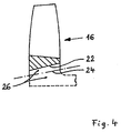
- FIG. 4 shows a partial longitudinal section through a blade unit 16, which is already welded to a joining surface 22 with an intermediate body 26.
- the illustration relates to a variant of the method in which the intermediate body 26 is first welded to one of the bodies to be joined, in this case the blade unit 16, and later to the second body to be connected, here the rotor base body (not shown).
- the intermediate body 26 is adapted by a self-supporting, solid construction to the loads during rotational friction welding. As soon as it is welded to the blade unit 16, a large part of its volume can be removed, for example by turning, the subsequently required joining surface 24 being manufactured, see the part of the intermediate body 26 below the dot-dashed joining surface 24 shown in dashed lines.
- the joining surfaces 22 and 24 may have the same cone direction and optionally the same cone angle. As a result, the joining surfaces 22 and 24 can move radially very close together so that weight and radial height can be saved with respect to the rotor to be produced.
- This time-consuming process variant with two separate Rotationsreibsch divorticiann and intermediate processing has the advantage that the separate welding of the intermediate body 26 with the usually forged rotor body on the one hand and with the usually cast blades on the other hand technically easier to control, since the process parameters are chosen differently thus can be better optimized.
- rotor 10 according to the invention and the method according to the invention can also be used with cooled rotors.
- rotor base body 12 and blade unit 16 have suitable cooling channels 50 (see FIG. 1 ).
- the intermediate body 26 also has, however, somewhat larger, cooling channels 52 in order to connect the channels 50 with each other regardless of its depth of immersion into the gap 20 in any case.
- the intermediate body would then have parallel, axial joining surfaces, wherein its radial thickness would have to be slightly larger for generating a contact pressure, as the radial gap width
Landscapes
- Engineering & Computer Science (AREA)
- Mechanical Engineering (AREA)
- Ceramic Engineering (AREA)
- General Engineering & Computer Science (AREA)
- Pressure Welding/Diffusion-Bonding (AREA)
- Turbine Rotor Nozzle Sealing (AREA)
Abstract
Description
Die Erfindung betrifft ein Verfahren zum Herstellen eines integral beschaufelten Rotors, insbesondere eines Gasturbinenrotors, mit einem Rotorgrundkörper und einer Schaufeleinheit.The invention relates to a method for producing an integrally bladed rotor, in particular a gas turbine rotor, having a rotor base body and a blade unit.
Darüber hinaus betrifft die vorliegende Erfindung einen entsprechend hergestellten Rotor selbst sowie eine Vorrichtung zur Durchführung des erfindungsgemäßen Verfahrens.Moreover, the present invention relates to a correspondingly produced rotor itself and to an apparatus for carrying out the method according to the invention.
Gasturbinenrotoren mit integraler Beschaufelung bezeichnet man abhängig davon, ob ein im Querschnitt scheibenförmiger oder ein im Querschnitt ringförmiger Rotor bzw. Rotorträger (im folgenden Rotorgrundkörper genannt) vorhanden ist, als Blisk bzw. Bling. Blisk ist die Grundform von bladed disk und Bling von bladed ring.Gas turbine rotors with integral blading are referred to as blisk or bling, depending on whether there is a disk-shaped rotor or rotor with a cross section in cross-section (referred to below as the rotor body). Blisk is the basic form of bladed disk and bling of bladed ring.
Aus dem Stand der Technik ist es bekannt, Gasturbinenrotoren mit integraler Beschaufelung durch Fräsen aus dem Vollen herzustellen, was natürlich sehr aufwendig und teuer ist, weshalb dieses Verfahren nur für relativ kleine Gasturbinenrotoren Verwendung gefunden hat.From the prior art it is known to produce gas turbine rotors with integral blading by milling from the solid, which is of course very complicated and expensive, which is why this method has found use only for relatively small gas turbine rotors use.
Ein anderes, bei großen Rotoren Anwendung findendes Verfahren ist das Reibschweißen. Dabei werden der Rotorgrundkörper und die Schaufeln separat hergestellt und anschließend miteinander reibverschweißt insbesondere durch Linearreibschweißen.
Aufgabe der Erfindung ist es, ein Verfahren zum Herstellen eines integral beschaufelten Rotors zu schaffen, mit dem die Turbinenschaufeln in sehr engen Toleranzen und damit positionsgenau am Rotorgrundkörper angebracht werden. Darüber hinaus soll eine möglichst einfache Vorrichtung zur Durchführung des Verfahrens angegeben werden.The object of the invention is to provide a method for producing an integrally bladed rotor, with which the turbine blades are mounted in very close tolerances and thus positionally accurate on the rotor body. In addition, the simplest possible device for carrying out the method should be specified.
Das erfindungsgemäße Verfahren sieht hierzu vor, dass Rotorgrundkörper und Schaufeleinheit über einen Zwischenkörper durch Rotationsschweißen verbunden werden, indem der Rotorgrundkörper und die Schaufeleinheit mit radialem Spalt positioniert werden, der Zwischenkörper koaxial fluchtend zum Spalt positioniert wird, und durch axiale sowie rotatorische Relativbewegung der zu verbindenden Teile relativ zum Zwischenkörper letzterer in den Spalt bewegt und simultan mit den zu verbindenden Teilen verschweißt wird.The inventive method provides for this purpose that rotor body and blade unit are connected via an intermediate body by spin welding by the rotor body and the blade unit are positioned with a radial gap, the intermediate body is coaxially aligned with the gap, and by axial and rotary relative movement of the parts to be joined moved relative to the intermediate body latter in the gap and is welded simultaneously with the parts to be joined.
Alternativ hierzu wird jeweils durch axiale sowie rotatorische Relativbewegung der Zwischenkörper zunächst mit einem ersten der zu verbindenden Teile (Rotorgrundkörper und Schaufeleinheit) verschweißt und danach, als integrale Einheit mit diesem Teil, mit dem zweiten der zu verbindenden Teile verschweißt.Alternatively, in each case by axial and rotary relative movement of the intermediate body is first welded to a first of the parts to be joined (rotor body and blade unit) and then, as an integral unit with this part, welded to the second of the parts to be joined.
Während im Stand der Technik die Rotorschaufeln direkt an den Rotorgrundkörper angeschweißt wurden und damit eine Relativbewegung dieser beiden Teile zueinander erfolgen musste, sieht die Erfindung vor, einen vorgefertigten Zwischenkörper durch Rotationsschweißen sozusagen als Brücke zwischen Rotorgrundkörper und Schaufeleinheit an beiden Einheiten festzuschweißen. Eine Relativbewegung zwischen Rotorgrundkörper und Schaufeleinheit beim Schweißen ist deshalb nicht mehr notwendig, diese beiden Teile können vorab fest zueinander positioniert werden. Die beim Reibschweißen auftretende Toleranz der zueinander bewegten Teile beeinflusst beim erfindungsgemäßen Verfahren nicht die Relativposition zwischen Rotorgrundkörper und Schaufeleinheit, so dass für die Lage des Zwischenkörpers im verschweißten Zustand größere Toleranzen akzeptabel sind. Darüber hinaus werden Rotorgrundkörper und Schaufeleinheit beim Schweißvorgang weniger belastet.While in the prior art, the rotor blades were welded directly to the rotor body and thus a relative movement of these two parts had to be made to each other, the invention provides a prefabricated intermediate body by spin welding so to speak as a bridge between the rotor body and blade unit on both units. A relative movement between the rotor base body and blade unit during welding is therefore no longer necessary, these two parts can be positioned in advance firmly to each other. In the method according to the invention, the tolerance of the moving parts occurring during friction welding does not influence the relative position between the rotor base body and the blade unit, so that larger tolerances are acceptable for the position of the intermediate body in the welded state. In addition, the rotor body and blade unit are less stressed during the welding process.
Wie bereits erläutert, wird gemäß der bevorzugten Ausführungsform nur der Zwischenkörper gedreht, wogegen die anderen beiden Einheiten unbewegt bleiben.As already explained, according to the preferred embodiment, only the intermediate body is rotated while the other two units remain stationary.
Die Schaufeleinheit ist gemäß der bevorzugten Ausführungsform ein geschlossener Schaufelkranz, das heißt, sie besteht aus einem Ringkörper und einstückig angeformten Schaufeln. Damit steht ein geschlossener Ringspalt zur Unterbringung des Zwischenkörpers zur Verfügung. Alternativ hierzu könnten natürlich auch mehrere Rotorschaufeln über ein Ringsegment einstückig miteinander verbunden sein, wobei die Ringsegmente über den Zwischenkörper miteinander verbunden werden. Darüber hinaus könnten sich theoretisch auch einzelne Laufschaufeln über verbreitete Laufschaufelfüße zu einem Ring ergänzen und sozusagen einzeln an den Zwischenkörper angeschweißt werden.The blade unit is according to the preferred embodiment, a closed blade ring, that is, it consists of a ring body and integrally formed blades. This is a closed annular gap for accommodating the intermediate body available. Alternatively, of course, a plurality of rotor blades could be integrally connected to each other via a ring segment, wherein the ring segments are connected to each other via the intermediate body. In addition, theoretically, individual rotor blades could also be supplemented by widespread rotor blade feet to form a ring and, so to speak, welded individually to the intermediate body.
Der Spalt sollte in Zustellrichtung des Zwischenteils enger werden, um durch die Zustellung eine zunehmend größere Reibkraft zu erzeugen.The gap should be narrower in the feed direction of the intermediate part in order to produce an increasingly greater frictional force by the delivery.
Besonders vorteilhaft ist es, wenn der Spalt kontinuierlich enger wird.It is particularly advantageous if the gap becomes continuously narrower.
Der Spalt kann beispielsweise konisch, wellenförmig oder treppenförmig enger werden, das heißt, die entsprechenden Fügeflächen an den zu verschweißenden Teilen haben daraufhin abgestimmte Geometrien.The gap can become narrower, for example conical, wavy or step-shaped, that is, the corresponding joining surfaces on the parts to be welded then have matched geometries.
Auch der Zwischenkörper kann oder sollte entsprechend angepasste Geometrien besitzen. Damit hätte der Zwischenkörper einen im weitesten Sinne doppelkonusförmigen Querschnitt.Also, the intermediate body may or should have correspondingly adapted geometries. Thus, the intermediate body would have a double-cone-shaped cross section in the broadest sense.
Die einzelnen oder segmentweise zusammengefassten Rotorschaufeln bilden dann zusammen die Schaufeleinheit.The individual or segmentally combined rotor blades then together form the blade unit.
Die den Spalt definierenden Fügeflächen des Rotorgrundkörpers und der Schaufeleinheit können, müssen jedoch nicht symmetrisch zur Axialrichtung geneigt sein. Durch unterschiedliche Neigungen lässt sich nämlich eine unterschiedliche Reibkraft an den Fügeflächen erzielen, was gegebenenfalls, abhängig von den einzelnen Materialien, vorteilhaft sein kann. Materialien und Reibkraft sind entsprechend einander anzupassen.The gap surfaces defining the rotor body and the blade unit can, but need not be symmetrical inclined to the axial direction. By different inclinations namely a different frictional force can be achieved at the joining surfaces, which may optionally, depending on the individual materials, may be advantageous. Materials and friction are to be adjusted accordingly.
Wie bereits zuvor erwähnt, sollte der Zwischenkörper eine auf die Spaltgeometrie abgestimmte, insbesondere der Spaltgeometrie entsprechende eigene Geometrie, aufweisen.As already mentioned above, the intermediate body should have a geometry matched to the geometry of the gap, in particular corresponding to the geometry of the gap.
Die Schaufeleinheit ist insbesondere ein geschlossener Schaufelkranz, wie bereits erläutert. Dabei kann dieser Schaufelkranz zum Beispiel integral gefertigt sein oder durch geeignete Verfahren, zum Beispiel Hochtemperaturlöten oder EB-Schweißen, ein aus Einzelteilen zusammengesetzter Ring sein.The blade unit is in particular a closed blade ring, as already explained. In this case, this blade ring can for example be produced integrally or by suitable methods, for example high-temperature soldering or EB welding, be a ring composed of individual parts.
Rotorgrundkörper und Schaufeleinheit sind bevorzugt aus unterschiedlichen Materialien.Rotor body and blade unit are preferably made of different materials.
Dies gilt auch für den Zwischenkörper. Der Zwischenkörper lässt sich nämlich auch aus unterschiedlichen Materialien im Bereich der Fügeflächen zusammensetzen, um ein Reibschweißen mit den angrenzenden Teilen sicherzustellen. Als Werkstoffe für den Zwischenkörper kommen alle rotationsreibschweißgeeigneten Nickelbasis-Legierungen in Frage, wobei der Zwischenkörper natürlich auch, wie erwähnt, ein sogenanntes Dual Alloy oder ein gradierter Werkstoff sein kann, der vorab aus geeigneten Werkstoffen hergestellt wird.This also applies to the intermediate body. Namely, the intermediate body can also be composed of different materials in the area of the joining surfaces in order to ensure friction welding with the adjacent parts. Suitable materials for the intermediate body are all rotationsreibschweißgeeigneten nickel-based alloys in question, wherein the intermediate body of course, as mentioned, a so-called dual alloy or a graded Material can be made in advance of suitable materials.
Vorteilhaft kann es auch sein, die zu verschweißenden Schaufeln oder, allgemeiner, die Schaufeleinheit, im Bereich der Fügefläche ganz oder selektiv durch Rekristallisation zu modifizieren. In diesem Zusammenhang hat sich herausgestellt, dass eine radiale Rekristallisationstiefe von mindestens 0,5 mm besonders geeignet ist.It can also be advantageous to modify the blades to be welded or, more generally, the blade unit in the area of the joining surface completely or selectively by recrystallization. In this context, it has been found that a radial recrystallization depth of at least 0.5 mm is particularly suitable.
Durch die Erfindung lassen sich auch Einkristall-Rotorschaufeln mit polykristallinen Rotorgrundkörpern verbinden.By means of the invention, it is also possible to connect single-crystal rotor blades with polycrystalline rotor main bodies.
Das erfindungsgemäße Verfahren sieht vor, dass die Schaufeleinheit in einer Vorrichtung lagefest und formschlüssig gehalten wird, während der Reibschweißvorgang erfolgt.The inventive method provides that the blade unit is held in a fixed position and a positive fit, while the friction welding process takes place.
Beim zweiten Verfahren, das zunächst die Herstellung einer integralen Einheit aus Zwischenkörper und einem ersten der zu verbindenden Teile vorsieht, wird der Zwischenkörper nach dem Anschweißen an den ersten der zu verbindenden Teile zum Teil, vorzugsweise zu mehr als 50 Prozent seines Volumens, abgetragen. Dabei wird die noch benötigte Fügefläche zum Anschweißen des zweiten Teiles gefertigt. Zu beachten ist, dass der zunächst als selbsttragender, an die Belastungen beim Rotationsschweißen angepasst ausgeführte Zwischenkörper dann natürlich soweit abgetragen werden kann, dass sein Volumen allein gegebenenfalls den Belastungen beim Rotationsschweißen nicht mehr gewachsen wäre. Aber, nachdem er mit dem ersten Teil ja eine vorgefertigte Einheit bildet, kann diese Einheit dann die beim Schweißen auftretenden Kräfte ohne weiteres aufnehmen.In the second method, which initially provides for the production of an integral unit of intermediate body and a first of the parts to be joined, the intermediate body is partially removed after welding to the first of the parts to be joined, preferably more than 50 percent of its volume. In this case, the still required joining surface for welding the second part is made. It should be noted that the initially executed as a self-supporting adapted to the loads during spin welding intermediate body then, of course, can be removed so far that its volume alone might not be equal to the loads during spin welding. But, after forming a prefabricated unit with the first part, this unit can then easily absorb the forces occurring during welding.
Die erfindungsgemäße Vorrichtung zur Durchführung des vorerwähnten Verfahrens umfasst eine Halterung für den Rotorgrundkörper und die Schaufeleinheit, Verdrehsicherungen für Rotorgrundkörper und Schaufeleinheit sowie eine drehbare und axial zustellbare Halterung für den Zwischenkörper.The device according to the invention for carrying out the above-mentioned method comprises a holder for the rotor base body and the blade unit, anti-rotation devices for the rotor base body and the blade unit and a rotatable and axially deliverable holder for the intermediate body.
Über die Halterung erfolgt die Lagepositionierung und Zentrierung der Teile zueinander, die Verdrehsicherungen halten die Teile beim Zustellen des rotierenden Zwischenkörpers.About the holder, the position positioning and centering of the parts to each other, the anti-rotation keep the parts when delivering the rotating intermediate body.
Wenn die Vorrichtung in Zustellrichtung nach dem Spalt eine Ausnehmung besitzt, besteht keine Gefahr, dass der Zwischenkörper beim Durchdringen des Spaltes die Vorrichtung kontaktiert.If the device has a recess in the feed direction after the gap, there is no danger that the intermediate body will contact the device when it penetrates the gap.
Die Verdrehsicherung für die Schaufeleinheit greift vorzugsweise formschlüssig in diese ein, was zwischen den Schaufeln und/oder an einem Ringabschnitt des Schaufelkranzes der Fall sein kann.The anti-rotation device for the blade unit preferably engages in a form-fitting manner, which may be the case between the blades and / or on a ring section of the blade ring.
Darüber hinaus sollte eine Zentriervorrichtung für den Rotorgrundkörper und für die Schaufeleinheit vorhanden sein.In addition, a centering device for the rotor body and the blade unit should be present.
Die Erfindung beschreibt schließlich auch einen integral beschaufelten Rotor, insbesondere für Gasturbinen, der nach dem erfindungsgemäßen Verfahren hergestellt wird und ein Zwischenteil besitzt, das durch Reibschweißen einen Spalt zwischen dem Rotorgrundkörper und der Schaufeleinheit überbrückt.Finally, the invention also describes an integrally bladed rotor, in particular for gas turbines, which is produced by the method according to the invention and has an intermediate part which bridges a gap between the rotor main body and the blade unit by friction welding.
Weitere Merkmale und Vorteile der Erfindung ergeben sich aus der nachfolgenden Beschreibung und aus den nachfolgenden Zeichnungen, auf die Bezug genommen wird. In den Zeichnungen zeigen:
-
Figur 1 einen Halbschnitt durch eine erfindungsgemäße Vorrichtung mit eingesetztem Rotor, in der integral beschaufelte Rotoren nach dem erfindungsgemäßen Verfahren hergestellt werden, -
Figur 2 einen Halbschnitt durch eine zweite Ausführungsform der erfindungsgemäßen Vorrichtung, bei der ebenfalls das erfindungsgemäße Verfahren durchgeführt werden kann, -
Figuren 3a und 3b je eine vergrößerte Ansicht des Rotors im Bereich des Spalts, und -
Figur 4 einen schematischen Teillängsschnitt durch eine temporäre Zwischenbaugruppe des erfindungsgemäßen Rotors.
-
FIG. 1 a half section through an inventive device with inserted rotor, are produced in the integrally bladed rotors according to the inventive method, -
FIG. 2 a half section through a second embodiment of the device according to the invention, in which also the method according to the invention can be carried out, -
FIGS. 3a and 3b depending on an enlarged view of the rotor in the region of the gap, and -
FIG. 4 a schematic partial longitudinal section through a temporary intermediate assembly of the rotor according to the invention.
In
Die Schaufeleinheit 16 hat einen radial inneren Ringkörper 18, von welchem aus sich die Turbinenschaufeln 14 radial nach außen erstrecken. Der Ringkörper 18 und die Turbinenschaufeln 14 können einstückig aus dem Vollen gemeinsam gefräst werden oder aus mehreren Bestandteilen bestehen und miteinander verbunden werden. Dies kann durch ein Hochtemperaturlötverfahren oder ein Schweißverfahren (zum Beispiel EB-Schweißen) erfolgen.The
Wie
Die Fügeflächen 22, 24 laufen in axialer Zustellrichtung Z des Zwischenkörpers 26 kontinuierlich konisch zu, so dass sich der Spalt radial zunehmend und kontinuierlich verringert.The joining surfaces 22, 24 run continuously conically in the axial feed direction Z of the
Auch der Zwischenkörper 26 hat eine entsprechend angepasste, doppelkonische Querschnittsform.Also, the
Die Fügeflächen 22, 24 sind zu ihren zugeordneten Fügeflächen am Zwischenkörper 26 im Querschnitt betrachtet, vorzugsweise parallel.The joining surfaces 22, 24 are considered to their associated joining surfaces on the
Bei der gezeigten Ausführungsform sind darüber hinaus die Fügeflächen 22, 24 symmetrisch zur Axialrichtung geneigt, das heißt die Winkel α und β sind vom Betrag her gleich. Alternativ können die Winkel auch ungleich sein, um bei unterschiedlichen Materialeigenschaften die Kräfte besser anpassen zukönnen.In the embodiment shown, moreover, the joining
Die Vorrichtung selbst umfasst eine radial äußere Zentriervorrichtung 28 in Form eines Absatzes, an dem innenseitig die radial äußere Stirnfläche der Turbinenschaufeln 14 anliegen. Darüber hinaus ist eine Verdrehsicherung 30 in Form von einem oder mehreren Vorsprüngen vorgesehen, die zwischen benachbarte Turbinenschaufeln 14 ragen und eine Drehung der Schaufeleinheit 16 verhindert bzw. verhindern.The device itself comprises a radially outer centering
Der Rotorgrundkörper 12 wird über einen Spannring 32, der auf einem axial verschieblichen Konus 34 sitzt, zentriert und lagefest, auch gegen Drehung, in der Vorrichtung gehalten, das heißt Spannring 32 und Konus 34 bilden auch eine Verdrehsicherung.The
In Axialrichtung stoßen Rotorgrundkörper 12 und Schaufeleinheit 16 gegen eine Wand 34 der Vorrichtung, so dass sie auch in Axialrichtung exakt zueinander und in der Vorrichtung positioniert und gehalten werden. Die Wand 34 besitzt in Zustellrichtung Z nach dem Spalt 20 eine ringförmige Ausnehmung 36, die in Radialrichtung größer als das angrenzende Ende des Spaltes 20 ist.In the axial direction, rotor
Der Zwischenkörper 26 wird auf einer drehbaren und axial zustellbaren Halterung 38 befestigt. Der Zwischenkörper 26 ist gemäß der dargestellten Ausführungsform ein ringförmiges, vorgefertigtes Element.The
Im folgenden wird die Herstellung des Rotors 10 kurz erläutert. Nach dem Einsetzen von Rotorgrundkörper 12 und Schaufeleinheit 16 sowie Fixieren dieser Teile in der Vorrichtung wird der an der Halterung 38 befestigte Zwischenkörper 26 in Rotation versetzt und in Zustellrichtung Z in den Spalt 20 gedrückt, wobei der Zwischenkörper 26 koaxial fluchtend zum Spalt 20 ausgerichtet ist. Die Winkel α und β sind gleich oder ungleich und auf die zu erzielende Reibung abgestimmt. Ab einer bestimmten Zustellkraft und der daraus resultierenden Reibkraft kommt es zum vorzugsweise simultanen Verschweißen der drei Teile, wobei dann natürlich der Zwischenkörper 26 den Spalt 20 überbrückt und vorzugsweise vollständig ausfüllt. Verglichen mit der Situation in
Während des Schweißvorgangs bleiben Rotorgrundkörper 12 und Schaufeleinheit 16 lagefest und drehen nicht mit.During the welding process, the
Rotorgrundkörper 12 und Schaufeleinheit 16 sind vorzugsweise aus unterschiedlichen Materialien, wobei auch der Zwischenkörper 26 aus verschiedenen Materialien bestehen kann, die an die Materialien der angrenzenden Teile des Rotors 10 angepasst sind. Folglich kann der Zwischenkörper 26 ein Dual Alloy oder gradierter Werkstoff sein. Als Werkstoffe können dabei zum Beispiel die rotationsreibschweißgeeigneten Nickelbasis-Legierungen Anwendung finden.
Darüber hinaus lässt sich auch die Schaufeleinheit 16 an ihrer Fügefläche modifizieren, und zwar durch Rekristallisation. Hier kann die gesamte Fügefläche 22 oder nur einzelne Abschnitte rekristallisiert werden, und zwar vorzugsweise bei einer Mindestrekristallisationstiefe von 0,5 mm.In addition, the
Nach dem Verschweißen des Zwischenkörpers 26 wird dieser von der Halterung 38 gelöst. Der vom hergestellten Rotor 10 abstehende Stumpf des Zwischenkörpers 26 wird dann abgedreht.After the welding of the
Die Ausführungsform nach
Für die Zentrierung der Schaufeleinheit 16 sorgt eine Zentriervorrichtung 28 in Form von Vorsprüngen, die an der Außenseite des Ringkörpers 18 anliegt und damit zwischen den Turbinenschaufeln 14 liegt.For the centering of the
Die übrigen bereits mit Bezug auf
Bei der Ausführungsform nach
Alternativ zur Arretierung der Schaufeleinheit 16 kann zusätzlich zu mechanischen Spannund Fixiervorrichtungen die Schaufeleinheit 16 mit einer niedrigschmelzenden metallischen Eingießmasse (zum Beispiel Zinn-Wismut) oder Kunststoff in die Vorrichtung eingegossen werden. Diese Masse wird nach dem Fügevorgang in geeigneter Weise wieder entfernt.As an alternative to locking the
Darüber hinaus ist zu betonen, dass der erfindungsgemäße Rotor 10 und das erfindungsgemäße Verfahren auch bei gekühlten Rotoren einsetzbar ist. Hierzu weisen beispielsweise Rotorgrundkörper 12 und Schaufeleinheit 16 geeignete Kühlkanäle 50 auf (siehe
Es wäre auch im Sinne der Erfindung, die Fügeflächen am Rotorgrundkörper und der Schaufeleinheit parallel und axial, d. h. mit in Zustellrichtung des Zwischenkörpers konstantem Radialspalt zueinander anzuordnen. Der Zwischenkörper hätte dann auch parallele, axiale Fügeflächen, wobei seine radiale Dicke zur Erzeugung einer Anpresskraft geringfügig größer sein müsste, als die radiale SpaltweiteIt would also be within the meaning of the invention, the joining surfaces on the rotor body and the blade unit in parallel and axially, d. H. to arrange with one another in the feed direction of the intermediate body constant radial gap. The intermediate body would then have parallel, axial joining surfaces, wherein its radial thickness would have to be slightly larger for generating a contact pressure, as the radial gap width
Claims (11)
- Method for producing an integrally bladed rotor (10), in particular a gas turbine rotor, having a rotor base body (12) and a blade unit (16), wherein the rotor base body (12) and the blade unit (16) are connected by way of an intermediate body (26) by means of rotary friction welding,
the rotor base body (12) and the blade unit (16) are produced from different materials,
in thatA) the rotor base body (12) and the blade unit (16) are positioned with a radial gap (20), the intermediate body (26) is positioned in coaxial alignment with the gap (20), and by means of axial and also rotatory relative movement of the portions (12, 16) that are to be connected relative to the intermediate body (26) the latter (26) is moved into the gap (20) and is simultaneously welded with the portions (12, 16) that are to be connected, or in thatB) in each case by means of axial and also rotatory relative movement the intermediate body (26) is first welded with a first portion (12 or 16) of the portions to be connected and afterwards, as an integral unit with this portion (12 or 16), is welded with the second portion (16 or 12) of the portions to be connected,characterised in that the joint surfaces (22, 24) of the rotor base body (12) and the blade unit (16) that define the gap (20) are inclined asymmetrically in relation to the axial direction. - Method according to claim 1, characterised in that the intermediate body (26) is turned and moved axially into the gap (20) in order to be friction-welded with the rotor base body (12) and the blade unit (16).
- Method according to claim 1 or 2, characterised in that the gap (20) becomes narrower in the direction of feed (Z) of the intermediate body (26) or extends so as to be constant and also radially slightly smaller than the intermediate body.
- Method according to one of the preceding claims, characterised in that in the feed direction the gap (20) becomes narrower in a conical, undulating or stepped manner.
- Method according to one of the preceding claims, characterised in that the intermediate body (26) has a geometry that is matched to the geometry of the gap, in particular corresponds to the geometry of the gap.
- Method according to one of the preceding claims, characterised in that the blade unit (16) is a closed blade ring.
- Method according to one of the preceding claims, characterised in that the intermediate body (26) consists of different materials on its opposing joint surfaces.
- Method according to one of the preceding claims, characterised in that the blade unit (16) is held in a device in a positionally fixed and form-closing manner during the friction welding.
- Method according to one of the preceding claims, characterised in that the blade unit (16) has a joint surface (22) co-defining the gap (20) and is recrystallized at least in sections in this region.
- Method according to one of the preceding claims, characterised in that the intermediate body (26), which in the first instance is constructed to be self-supporting and so as to be adapted to the loads during the rotary friction welding, is abraded in part, preferably to more than 50% of its volume, after the welding with a first portion (12 or 16) of the portions to be connected and prior to the welding with the second portion (16 or 12) of the portions to be connected, and a joint surface (22 or 24) that is further required is produced thereby.
- An integrally bladed rotor, in particular a gas turbine rotor, produced according to one of claims 1 to 10, having a rotor base body (12) and a blade unit (16), wherein the rotor base body (12) and the blade unit (16) are connected by way of an intermediate body (26) by means of rotary friction welding, the rotor base body (12) and the blade unit (16) are produced from different materials, and characterised in that the joint surfaces (22, 24) of the rotor base body (12) and the blade unit (16) are inclined asymmetrically in relation to the axial direction.
Applications Claiming Priority (2)
| Application Number | Priority Date | Filing Date | Title |
|---|---|---|---|
| DE102009013401A DE102009013401A1 (en) | 2009-03-16 | 2009-03-16 | Method for producing an integrally bladed rotor, rotor and apparatus for carrying out the method |
| PCT/DE2010/000268 WO2010105596A1 (en) | 2009-03-16 | 2010-03-15 | Method for producing an integrally bladed rotor, rotor and apparatus for carrying out the method |
Publications (2)
| Publication Number | Publication Date |
|---|---|
| EP2408584A1 EP2408584A1 (en) | 2012-01-25 |
| EP2408584B1 true EP2408584B1 (en) | 2013-12-18 |
Family
ID=42342731
Family Applications (1)
| Application Number | Title | Priority Date | Filing Date |
|---|---|---|---|
| EP10716270.3A Not-in-force EP2408584B1 (en) | 2009-03-16 | 2010-03-15 | Method for producing an integrally bladed rotor, rotor and apparatus for carrying out the method |
Country Status (3)
| Country | Link |
|---|---|
| EP (1) | EP2408584B1 (en) |
| DE (1) | DE102009013401A1 (en) |
| WO (1) | WO2010105596A1 (en) |
Families Citing this family (1)
| Publication number | Priority date | Publication date | Assignee | Title |
|---|---|---|---|---|
| CN112496685A (en) * | 2020-11-27 | 2021-03-16 | 中国航发四川燃气涡轮研究院 | Manufacturing method of blisk |
Family Cites Families (5)
| Publication number | Priority date | Publication date | Assignee | Title |
|---|---|---|---|---|
| DE2209473A1 (en) * | 1972-02-29 | 1973-09-06 | Audi Nsu Auto Union Ag | Assembling internal gear inside rotary piston - by friction welding with third ring |
| DE102005019356A1 (en) * | 2005-03-03 | 2006-09-07 | Mtu Aero Engines Gmbh | Joining two components, especially gas turbine rotor blade and rotor base structure, by friction welding method involving moving inserted joining piece between stationary components under compression force |
| DE102005026505A1 (en) * | 2005-06-09 | 2006-12-14 | Schaeffler Kg | Method for connecting two components by means of friction welding and welded connection |
| FR2903921B1 (en) * | 2006-07-19 | 2009-06-05 | Snecma Sa | METHOD FOR MANUFACTURING A MONOBLOCK AND MOLDING BLADE DISK FOR CARRYING OUT THE METHOD |
| DE102007036972A1 (en) * | 2007-08-04 | 2009-02-05 | Mtu Aero Engines Gmbh | Method for joining and joining connection of two components made of metal material |
-
2009
- 2009-03-16 DE DE102009013401A patent/DE102009013401A1/en not_active Withdrawn
-
2010
- 2010-03-15 WO PCT/DE2010/000268 patent/WO2010105596A1/en active Application Filing
- 2010-03-15 EP EP10716270.3A patent/EP2408584B1/en not_active Not-in-force
Also Published As
| Publication number | Publication date |
|---|---|
| WO2010105596A1 (en) | 2010-09-23 |
| DE102009013401A1 (en) | 2010-09-23 |
| EP2408584A1 (en) | 2012-01-25 |
Similar Documents
| Publication | Publication Date | Title |
|---|---|---|
| EP2215329B1 (en) | Production process for a rotor | |
| WO2009049596A1 (en) | Method for producing a blisk or a bling, component produced therewith and turbine blade | |
| EP3299117B1 (en) | Method for producing or repairing a component of a rotary machine and component produced or repaired according to such a method | |
| EP3251787A1 (en) | Method for producing a component of a rotary machine and component produced according to such a method | |
| EP2226146A1 (en) | Method of joining two, preferably rotationally symmetric, metallic workpieces by tungsten inert gas (TIG) welding and apparatus for carrying out this method | |
| DE102016113289A1 (en) | FSW tool with fixed shoulder | |
| EP2366870A2 (en) | Turbocharger rotor | |
| EP3501721A1 (en) | Method for joining components and device | |
| DE102005026505A1 (en) | Method for connecting two components by means of friction welding and welded connection | |
| EP2408584B1 (en) | Method for producing an integrally bladed rotor, rotor and apparatus for carrying out the method | |
| EP2219819B1 (en) | Method for the production of an integrally bladed rotor | |
| DE102012202272B4 (en) | Loader rotor and loader | |
| DE102013216354B4 (en) | Method of manufacturing a vane ring and vane ring | |
| EP2399006B1 (en) | Method of producing a rotor containing a plurality of blades and rotor | |
| WO2010099782A1 (en) | Method for producing an integrally bladed rotor | |
| EP1008722B1 (en) | Method for manufacturing a welded turbomachine rotor | |
| DE102009043184A1 (en) | Method for repairing an integral rotor and integral rotor | |
| DE102006061448B4 (en) | Method for producing a blisk or bling of a gas turbine and component produced thereafter | |
| WO2014146997A1 (en) | Additive method, in particular for producing a coating, device for performing the method, coating, component production method, and component | |
| EP2870322B1 (en) | Method and device for connecting a turbine wheel to an intermediate piece | |
| EP3508690A1 (en) | Turbine blade and method for its manufacture | |
| EP3254806A1 (en) | Method for producing a dressing tool for a grinding tool | |
| DE102009004926A1 (en) | Vane-integrated split disk of a turbine or compressor stage | |
| WO2022171240A1 (en) | Method for producing a flow structure for a turbomachine | |
| WO2020254019A1 (en) | Supporting structure, computer program product and method for removing the supporting structure |
Legal Events
| Date | Code | Title | Description |
|---|---|---|---|
| PUAI | Public reference made under article 153(3) epc to a published international application that has entered the european phase |
Free format text: ORIGINAL CODE: 0009012 |
|
| 17P | Request for examination filed |
Effective date: 20110808 |
|
| AK | Designated contracting states |
Kind code of ref document: A1 Designated state(s): AT BE BG CH CY CZ DE DK EE ES FI FR GB GR HR HU IE IS IT LI LT LU LV MC MK MT NL NO PL PT RO SE SI SK SM TR |
|
| DAX | Request for extension of the european patent (deleted) | ||
| GRAP | Despatch of communication of intention to grant a patent |
Free format text: ORIGINAL CODE: EPIDOSNIGR1 |
|
| INTG | Intention to grant announced |
Effective date: 20130906 |
|
| RAP1 | Party data changed (applicant data changed or rights of an application transferred) |
Owner name: MTU AERO ENGINES AG |
|
| GRAS | Grant fee paid |
Free format text: ORIGINAL CODE: EPIDOSNIGR3 |
|
| GRAA | (expected) grant |
Free format text: ORIGINAL CODE: 0009210 |
|
| AK | Designated contracting states |
Kind code of ref document: B1 Designated state(s): AT BE BG CH CY CZ DE DK EE ES FI FR GB GR HR HU IE IS IT LI LT LU LV MC MK MT NL NO PL PT RO SE SI SK SM TR |
|
| REG | Reference to a national code |
Ref country code: GB Ref legal event code: FG4D Free format text: NOT ENGLISH |
|
| REG | Reference to a national code |
Ref country code: CH Ref legal event code: EP |
|
| REG | Reference to a national code |
Ref country code: AT Ref legal event code: REF Ref document number: 645394 Country of ref document: AT Kind code of ref document: T Effective date: 20140115 |
|
| REG | Reference to a national code |
Ref country code: IE Ref legal event code: FG4D Free format text: LANGUAGE OF EP DOCUMENT: GERMAN |
|
| REG | Reference to a national code |
Ref country code: DE Ref legal event code: R096 Ref document number: 502010005706 Country of ref document: DE Effective date: 20140213 |
|
| REG | Reference to a national code |
Ref country code: NL Ref legal event code: VDEP Effective date: 20131218 |
|
| PG25 | Lapsed in a contracting state [announced via postgrant information from national office to epo] |
Ref country code: HR Free format text: LAPSE BECAUSE OF FAILURE TO SUBMIT A TRANSLATION OF THE DESCRIPTION OR TO PAY THE FEE WITHIN THE PRESCRIBED TIME-LIMIT Effective date: 20131218 Ref country code: LT Free format text: LAPSE BECAUSE OF FAILURE TO SUBMIT A TRANSLATION OF THE DESCRIPTION OR TO PAY THE FEE WITHIN THE PRESCRIBED TIME-LIMIT Effective date: 20131218 Ref country code: NO Free format text: LAPSE BECAUSE OF FAILURE TO SUBMIT A TRANSLATION OF THE DESCRIPTION OR TO PAY THE FEE WITHIN THE PRESCRIBED TIME-LIMIT Effective date: 20140318 Ref country code: SE Free format text: LAPSE BECAUSE OF FAILURE TO SUBMIT A TRANSLATION OF THE DESCRIPTION OR TO PAY THE FEE WITHIN THE PRESCRIBED TIME-LIMIT Effective date: 20131218 Ref country code: FI Free format text: LAPSE BECAUSE OF FAILURE TO SUBMIT A TRANSLATION OF THE DESCRIPTION OR TO PAY THE FEE WITHIN THE PRESCRIBED TIME-LIMIT Effective date: 20131218 |
|
| REG | Reference to a national code |
Ref country code: LT Ref legal event code: MG4D |
|
| PG25 | Lapsed in a contracting state [announced via postgrant information from national office to epo] |
Ref country code: LV Free format text: LAPSE BECAUSE OF FAILURE TO SUBMIT A TRANSLATION OF THE DESCRIPTION OR TO PAY THE FEE WITHIN THE PRESCRIBED TIME-LIMIT Effective date: 20131218 |
|
| PG25 | Lapsed in a contracting state [announced via postgrant information from national office to epo] |
Ref country code: IS Free format text: LAPSE BECAUSE OF FAILURE TO SUBMIT A TRANSLATION OF THE DESCRIPTION OR TO PAY THE FEE WITHIN THE PRESCRIBED TIME-LIMIT Effective date: 20140418 Ref country code: EE Free format text: LAPSE BECAUSE OF FAILURE TO SUBMIT A TRANSLATION OF THE DESCRIPTION OR TO PAY THE FEE WITHIN THE PRESCRIBED TIME-LIMIT Effective date: 20131218 |
|
| PG25 | Lapsed in a contracting state [announced via postgrant information from national office to epo] |
Ref country code: RO Free format text: LAPSE BECAUSE OF FAILURE TO SUBMIT A TRANSLATION OF THE DESCRIPTION OR TO PAY THE FEE WITHIN THE PRESCRIBED TIME-LIMIT Effective date: 20131218 Ref country code: ES Free format text: LAPSE BECAUSE OF FAILURE TO SUBMIT A TRANSLATION OF THE DESCRIPTION OR TO PAY THE FEE WITHIN THE PRESCRIBED TIME-LIMIT Effective date: 20131218 Ref country code: CZ Free format text: LAPSE BECAUSE OF FAILURE TO SUBMIT A TRANSLATION OF THE DESCRIPTION OR TO PAY THE FEE WITHIN THE PRESCRIBED TIME-LIMIT Effective date: 20131218 Ref country code: PL Free format text: LAPSE BECAUSE OF FAILURE TO SUBMIT A TRANSLATION OF THE DESCRIPTION OR TO PAY THE FEE WITHIN THE PRESCRIBED TIME-LIMIT Effective date: 20131218 Ref country code: NL Free format text: LAPSE BECAUSE OF FAILURE TO SUBMIT A TRANSLATION OF THE DESCRIPTION OR TO PAY THE FEE WITHIN THE PRESCRIBED TIME-LIMIT Effective date: 20131218 Ref country code: SK Free format text: LAPSE BECAUSE OF FAILURE TO SUBMIT A TRANSLATION OF THE DESCRIPTION OR TO PAY THE FEE WITHIN THE PRESCRIBED TIME-LIMIT Effective date: 20131218 Ref country code: PT Free format text: LAPSE BECAUSE OF FAILURE TO SUBMIT A TRANSLATION OF THE DESCRIPTION OR TO PAY THE FEE WITHIN THE PRESCRIBED TIME-LIMIT Effective date: 20140418 Ref country code: CY Free format text: LAPSE BECAUSE OF FAILURE TO SUBMIT A TRANSLATION OF THE DESCRIPTION OR TO PAY THE FEE WITHIN THE PRESCRIBED TIME-LIMIT Effective date: 20131218 |
|
| REG | Reference to a national code |
Ref country code: DE Ref legal event code: R097 Ref document number: 502010005706 Country of ref document: DE |
|
| PLBE | No opposition filed within time limit |
Free format text: ORIGINAL CODE: 0009261 |
|
| STAA | Information on the status of an ep patent application or granted ep patent |
Free format text: STATUS: NO OPPOSITION FILED WITHIN TIME LIMIT |
|
| PG25 | Lapsed in a contracting state [announced via postgrant information from national office to epo] |
Ref country code: LU Free format text: LAPSE BECAUSE OF FAILURE TO SUBMIT A TRANSLATION OF THE DESCRIPTION OR TO PAY THE FEE WITHIN THE PRESCRIBED TIME-LIMIT Effective date: 20140315 Ref country code: DK Free format text: LAPSE BECAUSE OF FAILURE TO SUBMIT A TRANSLATION OF THE DESCRIPTION OR TO PAY THE FEE WITHIN THE PRESCRIBED TIME-LIMIT Effective date: 20131218 |
|
| REG | Reference to a national code |
Ref country code: CH Ref legal event code: PL |
|
| 26N | No opposition filed |
Effective date: 20140919 |
|
| REG | Reference to a national code |
Ref country code: IE Ref legal event code: MM4A Ref country code: DE Ref legal event code: R097 Ref document number: 502010005706 Country of ref document: DE Effective date: 20140919 |
|
| PG25 | Lapsed in a contracting state [announced via postgrant information from national office to epo] |
Ref country code: CH Free format text: LAPSE BECAUSE OF NON-PAYMENT OF DUE FEES Effective date: 20140331 Ref country code: LI Free format text: LAPSE BECAUSE OF NON-PAYMENT OF DUE FEES Effective date: 20140331 Ref country code: IE Free format text: LAPSE BECAUSE OF NON-PAYMENT OF DUE FEES Effective date: 20140315 |
|
| PG25 | Lapsed in a contracting state [announced via postgrant information from national office to epo] |
Ref country code: SI Free format text: LAPSE BECAUSE OF FAILURE TO SUBMIT A TRANSLATION OF THE DESCRIPTION OR TO PAY THE FEE WITHIN THE PRESCRIBED TIME-LIMIT Effective date: 20131218 |
|
| PG25 | Lapsed in a contracting state [announced via postgrant information from national office to epo] |
Ref country code: MT Free format text: LAPSE BECAUSE OF FAILURE TO SUBMIT A TRANSLATION OF THE DESCRIPTION OR TO PAY THE FEE WITHIN THE PRESCRIBED TIME-LIMIT Effective date: 20131218 |
|
| REG | Reference to a national code |
Ref country code: FR Ref legal event code: PLFP Year of fee payment: 7 |
|
| PG25 | Lapsed in a contracting state [announced via postgrant information from national office to epo] |
Ref country code: SM Free format text: LAPSE BECAUSE OF FAILURE TO SUBMIT A TRANSLATION OF THE DESCRIPTION OR TO PAY THE FEE WITHIN THE PRESCRIBED TIME-LIMIT Effective date: 20131218 |
|
| REG | Reference to a national code |
Ref country code: AT Ref legal event code: MM01 Ref document number: 645394 Country of ref document: AT Kind code of ref document: T Effective date: 20150315 |
|
| PG25 | Lapsed in a contracting state [announced via postgrant information from national office to epo] |
Ref country code: MC Free format text: LAPSE BECAUSE OF FAILURE TO SUBMIT A TRANSLATION OF THE DESCRIPTION OR TO PAY THE FEE WITHIN THE PRESCRIBED TIME-LIMIT Effective date: 20131218 |
|
| PG25 | Lapsed in a contracting state [announced via postgrant information from national office to epo] |
Ref country code: BG Free format text: LAPSE BECAUSE OF FAILURE TO SUBMIT A TRANSLATION OF THE DESCRIPTION OR TO PAY THE FEE WITHIN THE PRESCRIBED TIME-LIMIT Effective date: 20131218 Ref country code: GR Free format text: LAPSE BECAUSE OF FAILURE TO SUBMIT A TRANSLATION OF THE DESCRIPTION OR TO PAY THE FEE WITHIN THE PRESCRIBED TIME-LIMIT Effective date: 20140319 Ref country code: IT Free format text: LAPSE BECAUSE OF FAILURE TO SUBMIT A TRANSLATION OF THE DESCRIPTION OR TO PAY THE FEE WITHIN THE PRESCRIBED TIME-LIMIT Effective date: 20131218 |
|
| PG25 | Lapsed in a contracting state [announced via postgrant information from national office to epo] |
Ref country code: TR Free format text: LAPSE BECAUSE OF FAILURE TO SUBMIT A TRANSLATION OF THE DESCRIPTION OR TO PAY THE FEE WITHIN THE PRESCRIBED TIME-LIMIT Effective date: 20131218 Ref country code: HU Free format text: LAPSE BECAUSE OF FAILURE TO SUBMIT A TRANSLATION OF THE DESCRIPTION OR TO PAY THE FEE WITHIN THE PRESCRIBED TIME-LIMIT; INVALID AB INITIO Effective date: 20100315 Ref country code: BE Free format text: LAPSE BECAUSE OF FAILURE TO SUBMIT A TRANSLATION OF THE DESCRIPTION OR TO PAY THE FEE WITHIN THE PRESCRIBED TIME-LIMIT Effective date: 20140331 |
|
| PG25 | Lapsed in a contracting state [announced via postgrant information from national office to epo] |
Ref country code: AT Free format text: LAPSE BECAUSE OF NON-PAYMENT OF DUE FEES Effective date: 20150315 |
|
| REG | Reference to a national code |
Ref country code: FR Ref legal event code: PLFP Year of fee payment: 8 |
|
| REG | Reference to a national code |
Ref country code: FR Ref legal event code: PLFP Year of fee payment: 9 |
|
| PGFP | Annual fee paid to national office [announced via postgrant information from national office to epo] |
Ref country code: DE Payment date: 20180322 Year of fee payment: 9 Ref country code: GB Payment date: 20180326 Year of fee payment: 9 |
|
| PGFP | Annual fee paid to national office [announced via postgrant information from national office to epo] |
Ref country code: FR Payment date: 20180326 Year of fee payment: 9 |
|
| PG25 | Lapsed in a contracting state [announced via postgrant information from national office to epo] |
Ref country code: MK Free format text: LAPSE BECAUSE OF FAILURE TO SUBMIT A TRANSLATION OF THE DESCRIPTION OR TO PAY THE FEE WITHIN THE PRESCRIBED TIME-LIMIT Effective date: 20131218 |
|
| REG | Reference to a national code |
Ref country code: DE Ref legal event code: R119 Ref document number: 502010005706 Country of ref document: DE |
|
| GBPC | Gb: european patent ceased through non-payment of renewal fee |
Effective date: 20190315 |
|
| PG25 | Lapsed in a contracting state [announced via postgrant information from national office to epo] |
Ref country code: GB Free format text: LAPSE BECAUSE OF NON-PAYMENT OF DUE FEES Effective date: 20190315 Ref country code: DE Free format text: LAPSE BECAUSE OF NON-PAYMENT OF DUE FEES Effective date: 20191001 |
|
| PG25 | Lapsed in a contracting state [announced via postgrant information from national office to epo] |
Ref country code: FR Free format text: LAPSE BECAUSE OF NON-PAYMENT OF DUE FEES Effective date: 20190331 |