EP2402737A1 - Method and device for operating a traction aid of a vehicle - Google Patents
Method and device for operating a traction aid of a vehicle Download PDFInfo
- Publication number
- EP2402737A1 EP2402737A1 EP11004395A EP11004395A EP2402737A1 EP 2402737 A1 EP2402737 A1 EP 2402737A1 EP 11004395 A EP11004395 A EP 11004395A EP 11004395 A EP11004395 A EP 11004395A EP 2402737 A1 EP2402737 A1 EP 2402737A1
- Authority
- EP
- European Patent Office
- Prior art keywords
- light
- road surface
- traction aid
- vehicle
- detector
- Prior art date
- Legal status (The legal status is an assumption and is not a legal conclusion. Google has not performed a legal analysis and makes no representation as to the accuracy of the status listed.)
- Withdrawn
Links
- 238000000034 method Methods 0.000 title claims abstract description 26
- 230000003287 optical effect Effects 0.000 claims description 35
- 230000023077 detection of light stimulus Effects 0.000 claims 1
- 239000000758 substrate Substances 0.000 claims 1
- 230000010287 polarization Effects 0.000 description 23
- XLYOFNOQVPJJNP-UHFFFAOYSA-N water Substances O XLYOFNOQVPJJNP-UHFFFAOYSA-N 0.000 description 15
- 238000011156 evaluation Methods 0.000 description 11
- 230000003595 spectral effect Effects 0.000 description 5
- 238000005259 measurement Methods 0.000 description 3
- 238000010183 spectrum analysis Methods 0.000 description 3
- 239000010426 asphalt Substances 0.000 description 2
- 230000005693 optoelectronics Effects 0.000 description 2
- 240000001439 Opuntia Species 0.000 description 1
- 235000004727 Opuntia ficus indica Nutrition 0.000 description 1
- 238000010521 absorption reaction Methods 0.000 description 1
- 238000001514 detection method Methods 0.000 description 1
- 230000000694 effects Effects 0.000 description 1
- 230000005855 radiation Effects 0.000 description 1
- 238000009420 retrofitting Methods 0.000 description 1
- 230000003746 surface roughness Effects 0.000 description 1
Images


Classifications
-
- B—PERFORMING OPERATIONS; TRANSPORTING
- B60—VEHICLES IN GENERAL
- B60G—VEHICLE SUSPENSION ARRANGEMENTS
- B60G17/00—Resilient suspensions having means for adjusting the spring or vibration-damper characteristics, for regulating the distance between a supporting surface and a sprung part of vehicle or for locking suspension during use to meet varying vehicular or surface conditions, e.g. due to speed or load
- B60G17/015—Resilient suspensions having means for adjusting the spring or vibration-damper characteristics, for regulating the distance between a supporting surface and a sprung part of vehicle or for locking suspension during use to meet varying vehicular or surface conditions, e.g. due to speed or load the regulating means comprising electric or electronic elements
- B60G17/019—Resilient suspensions having means for adjusting the spring or vibration-damper characteristics, for regulating the distance between a supporting surface and a sprung part of vehicle or for locking suspension during use to meet varying vehicular or surface conditions, e.g. due to speed or load the regulating means comprising electric or electronic elements characterised by the type of sensor or the arrangement thereof
-
- B—PERFORMING OPERATIONS; TRANSPORTING
- B60—VEHICLES IN GENERAL
- B60G—VEHICLE SUSPENSION ARRANGEMENTS
- B60G17/00—Resilient suspensions having means for adjusting the spring or vibration-damper characteristics, for regulating the distance between a supporting surface and a sprung part of vehicle or for locking suspension during use to meet varying vehicular or surface conditions, e.g. due to speed or load
- B60G17/015—Resilient suspensions having means for adjusting the spring or vibration-damper characteristics, for regulating the distance between a supporting surface and a sprung part of vehicle or for locking suspension during use to meet varying vehicular or surface conditions, e.g. due to speed or load the regulating means comprising electric or electronic elements
- B60G17/0195—Resilient suspensions having means for adjusting the spring or vibration-damper characteristics, for regulating the distance between a supporting surface and a sprung part of vehicle or for locking suspension during use to meet varying vehicular or surface conditions, e.g. due to speed or load the regulating means comprising electric or electronic elements characterised by the regulation being combined with other vehicle control systems
-
- B—PERFORMING OPERATIONS; TRANSPORTING
- B60—VEHICLES IN GENERAL
- B60W—CONJOINT CONTROL OF VEHICLE SUB-UNITS OF DIFFERENT TYPE OR DIFFERENT FUNCTION; CONTROL SYSTEMS SPECIALLY ADAPTED FOR HYBRID VEHICLES; ROAD VEHICLE DRIVE CONTROL SYSTEMS FOR PURPOSES NOT RELATED TO THE CONTROL OF A PARTICULAR SUB-UNIT
- B60W40/00—Estimation or calculation of non-directly measurable driving parameters for road vehicle drive control systems not related to the control of a particular sub unit, e.g. by using mathematical models
- B60W40/02—Estimation or calculation of non-directly measurable driving parameters for road vehicle drive control systems not related to the control of a particular sub unit, e.g. by using mathematical models related to ambient conditions
- B60W40/06—Road conditions
- B60W40/068—Road friction coefficient
-
- G—PHYSICS
- G01—MEASURING; TESTING
- G01N—INVESTIGATING OR ANALYSING MATERIALS BY DETERMINING THEIR CHEMICAL OR PHYSICAL PROPERTIES
- G01N21/00—Investigating or analysing materials by the use of optical means, i.e. using sub-millimetre waves, infrared, visible or ultraviolet light
- G01N21/17—Systems in which incident light is modified in accordance with the properties of the material investigated
- G01N21/25—Colour; Spectral properties, i.e. comparison of effect of material on the light at two or more different wavelengths or wavelength bands
- G01N21/31—Investigating relative effect of material at wavelengths characteristic of specific elements or molecules, e.g. atomic absorption spectrometry
- G01N21/35—Investigating relative effect of material at wavelengths characteristic of specific elements or molecules, e.g. atomic absorption spectrometry using infrared light
- G01N21/3554—Investigating relative effect of material at wavelengths characteristic of specific elements or molecules, e.g. atomic absorption spectrometry using infrared light for determining moisture content
-
- G—PHYSICS
- G01—MEASURING; TESTING
- G01N—INVESTIGATING OR ANALYSING MATERIALS BY DETERMINING THEIR CHEMICAL OR PHYSICAL PROPERTIES
- G01N21/00—Investigating or analysing materials by the use of optical means, i.e. using sub-millimetre waves, infrared, visible or ultraviolet light
- G01N21/17—Systems in which incident light is modified in accordance with the properties of the material investigated
- G01N21/55—Specular reflectivity
-
- B—PERFORMING OPERATIONS; TRANSPORTING
- B60—VEHICLES IN GENERAL
- B60G—VEHICLE SUSPENSION ARRANGEMENTS
- B60G2400/00—Indexing codes relating to detected, measured or calculated conditions or factors
- B60G2400/80—Exterior conditions
- B60G2400/82—Ground surface
-
- B—PERFORMING OPERATIONS; TRANSPORTING
- B60—VEHICLES IN GENERAL
- B60G—VEHICLE SUSPENSION ARRANGEMENTS
- B60G2400/00—Indexing codes relating to detected, measured or calculated conditions or factors
- B60G2400/80—Exterior conditions
- B60G2400/82—Ground surface
- B60G2400/822—Road friction coefficient determination affecting wheel traction
-
- B—PERFORMING OPERATIONS; TRANSPORTING
- B60—VEHICLES IN GENERAL
- B60Y—INDEXING SCHEME RELATING TO ASPECTS CROSS-CUTTING VEHICLE TECHNOLOGY
- B60Y2200/00—Type of vehicle
- B60Y2200/10—Road Vehicles
- B60Y2200/14—Trucks; Load vehicles, Busses
-
- G—PHYSICS
- G01—MEASURING; TESTING
- G01N—INVESTIGATING OR ANALYSING MATERIALS BY DETERMINING THEIR CHEMICAL OR PHYSICAL PROPERTIES
- G01N21/00—Investigating or analysing materials by the use of optical means, i.e. using sub-millimetre waves, infrared, visible or ultraviolet light
- G01N21/17—Systems in which incident light is modified in accordance with the properties of the material investigated
- G01N21/21—Polarisation-affecting properties
-
- G—PHYSICS
- G01—MEASURING; TESTING
- G01N—INVESTIGATING OR ANALYSING MATERIALS BY DETERMINING THEIR CHEMICAL OR PHYSICAL PROPERTIES
- G01N21/00—Investigating or analysing materials by the use of optical means, i.e. using sub-millimetre waves, infrared, visible or ultraviolet light
- G01N21/17—Systems in which incident light is modified in accordance with the properties of the material investigated
- G01N21/25—Colour; Spectral properties, i.e. comparison of effect of material on the light at two or more different wavelengths or wavelength bands
- G01N21/31—Investigating relative effect of material at wavelengths characteristic of specific elements or molecules, e.g. atomic absorption spectrometry
- G01N21/314—Investigating relative effect of material at wavelengths characteristic of specific elements or molecules, e.g. atomic absorption spectrometry with comparison of measurements at specific and non-specific wavelengths
-
- G—PHYSICS
- G01—MEASURING; TESTING
- G01N—INVESTIGATING OR ANALYSING MATERIALS BY DETERMINING THEIR CHEMICAL OR PHYSICAL PROPERTIES
- G01N21/00—Investigating or analysing materials by the use of optical means, i.e. using sub-millimetre waves, infrared, visible or ultraviolet light
- G01N21/17—Systems in which incident light is modified in accordance with the properties of the material investigated
- G01N21/47—Scattering, i.e. diffuse reflection
- G01N21/4738—Diffuse reflection, e.g. also for testing fluids, fibrous materials
Definitions
- the present description relates to traction aids for vehicles. More particularly, the present description relates to a method and apparatus for controlling automatic traction aids on commercial vehicles.
- automatic traction aids which allow the driver to turn on in uncertain road conditions, the traction aid, whereby the manual and time-consuming application of snow chains is avoided.
- automatic snow chains are known, which may be attached to commercial vehicles, especially in trucks on the drive axles and are applied by means of a sling mechanism between the road and tires to increase the traction on a slippery surface, such as a snowy or icy road.
- These known automatic snow chains are operated manually by the driver.
- a traction aid for commercial vehicles it is also known in multiaxial vehicles, which have, for example, a third auxiliary axis, to temporarily relieve or increase these auxiliary axes and thus increase the axle load on the remaining axes and in particular on driven axles. Due to the increased axle load and increased traction in slippery road conditions can be achieved. It is possible to exceed the officially permitted maximum axle load in the short term in order to achieve the necessary traction, for example, as traction help.
- axle load control is for example from the documents DE 39 29 788 C2 .
- the invention proposes a method according to claim 1 and an apparatus according to claim 8 for controlling a traction aid of a vehicle.
- the invention relates to a vehicle which is equipped with a corresponding device and in which the method according to the invention is carried out.
- the inventive method for controlling a traction aid of a vehicle comprises emitting light of at least one wavelength on a road surface under the vehicle, detecting light of the at least one wavelength reflected on the road surface, determining at least one information about the nature of the road surface using the detected reflected light of the at least one wavelength, a determination based on the at least one information, whether the coefficient of friction of the road surface requires a traction aid and / or whether the traction aid is no longer required, a corresponding Control the traction aid when it has been determined whether the traction aid is required or no longer required.
- the device for controlling a traction aid of a vehicle comprises an optical surface sensor for detecting at least one information about the nature of a road surface and a controller which is connected to the optical surface sensor and the traction aid and controls the traction aid based on the at least one information about the road surface.
- the optical determination of the condition of the road surface or by determining at least one information about the road condition can be determined automatically, reliably and contactless, whether the road surface is wet, icy, snowy and / or dry, that is, in which state the road surface is. Furthermore, it can be determined which type the roadway is, that is, whether the roadway is an asphalt, a concrete carriageway or another road surface.
- the optical sensor without direct road contact is less prone to failure, especially against icing and whirling snow, as it has no mechanical part. Further, the optical sensor can be protected at any location in the lower area of the vehicle.
- optical sensor It can also be determined with the optical sensor, whether it is an icy roadway to a certain thickness of ice or a water film to a certain water film thickness.
- the optical sensor therefore provides more accurate information about the condition, especially about the condition of the road surface, e.g. mechanical sensors.
- the traction aid is automatically activated. It is also possible that before the connection of the traction help further parameters, such as the vehicle speed, the presence of a slope or other is queried.
- the device and the method make it possible to switch on the traction aid as soon as a road surface with a low coefficient of friction has been detected, and thus possibly before a dangerous situation can arise for the vehicle.
- a traction aid can be automatically activated even when the vehicle is stationary, since the optical surface sensor or the optical method can already detect the slippery road surface or the reduced coefficient of friction independently of vehicle movement.
- the method and apparatus may also be used to turn off a traction aid when the condition or condition of the road surface makes it unnecessary. If the optical surface sensor recognizes, for example, that the road is no longer icy and / or is no longer covered in snow, but is, for example, wet or dry, the traction aid can be automatically switched off. An unnecessary wear can be prevented. Should the road condition deteriorate again and possibly an icy or snowy road surface be recognized again, then the traction aid can be switched on again.
- the traction aid may comprise automatic snow chains, as they are known in the art.
- the traction aid may also include an axle relief, as is known in the art also from the prior art.
- the traction aid may also include braking the driven wheels.
- the device may also comprise a combination of said traction aids.
- the method and the device it is possible to automatically switch on a traction aid even when the vehicle is stationary, since the optical surface sensor or the optical method can already detect the slippery road surface or the reduced coefficient of friction before starting.
- the optical surface sensor of the device may include a light source unit for emitting light of at least one wavelength to the ground and at least one detector for detecting light reflected from the ground.
- the surface sensor may comprise a second detector in addition to the first detector, wherein the first detector for detecting diffusely reflected light and the second detector for detecting specularly reflected light are suitable.
- At least two polarizers can be provided, wherein a first polarizer having a first polarization device is assigned to the first detector.
- the light source unit may be a Lichtierinpolarisator and / or the second detector may be associated with a second polarizer whose polarization direction (s) is oriented substantially perpendicular to the first polarization direction of the first polarizer / are. If at least two polarizers or polarization filters are provided, the first polarizer is arranged on the first detector, which transmits only light waves in the first polarization direction to the first detector.
- a light source polarizer When a light source polarizer is provided on the light source unit, its polarization direction is substantially perpendicular to the first polarization direction of the first polarizer, and the light emitted from the sensor is polarized in a direction substantially perpendicular to the first polarization direction, so that polarized at the first detector , Reflected reflected light filtered out and only diffuse reflected light is detected.
- a similar effect can be achieved if a second polarizer is arranged in front of the second detector whose polarization direction is oriented substantially perpendicular to the first polarization direction.
- the second polarizer may be used alternatively or in addition to the light source polarizer. It can also be provided to generate already polarized light in the light source unit
- the light source unit can be designed to emit light of at least two mutually different wavelengths or to emit a plurality of wavelengths onto the ground or the road surface.
- the light source unit may for example comprise a plurality of light sources.
- the use of at least two, preferably three, of different wavelengths makes it possible to operate the sensor in a spectral manner.
- wavelengths which are e.g. ice or water can be detected on the road surface when the reflected light of the wavelength absorbed by the water or ice is compared with that of a reference wavelength. It is thus possible to implement the principles of spectral analysis and diffuse and specular reflection in a single device or housing.
- the at least one light source unit, the first detector and possibly the second detector can be arranged for this purpose in a common single and / or one-piece housing, for example directly next to one another.
- the light source unit may for this purpose comprise a plurality of light sources.
- the light source unit may be configured to emit infrared light of the wavelengths 1300 nm, 1460 nm and 1550 nm. While light of wavelength 1460 nm is particularly well absorbed by water, light of wavelength 1550 nm is well absorbed by ice. Light in the range of about 1300 nm can then be used as the reference wavelength. However, other wavelengths may be used. In particular, for the reference wavelength, any other wavelength can be used which is not significantly absorbed by neither ice nor water. As a water-sensitive wavelength, any other wavelength can be used be absorbed, which is increased in water.
- each wave length can be chosen as the pseudo-wavelength, which is absorbed in ice.
- Other interesting wavelengths include, for example, 1190, 1040, 970, 880 and 810 nm in the infrared range, as well as the visible wavelengths 625, 530 and 470 nm.
- the light source unit may be configured to emit light of exactly three different wavelengths.
- the light source unit can have three light sources, one light source for each wavelength. Only the three wavelengths are used to detect both spectral and specular / diffuse reflected light to detect both the road condition and the type of roadway.
- Each of the light sources can be controlled individually and switched on and off independently of the other or be adjustable in intensity.
- the wavelength 625 nm can also be used to measure the diffused and specularly reflected light.
- the modulation of the intensity or amplitude can be done by turning on and off all or individual light sources of the light source unit.
- the modulation of the intensity or the switching on and off can be carried out separately for each wavelength of the light source unit or for each light source of the light source unit.
- the light of the first wavelength may be provided to emit light of a first wavelength for a specific time interval, then the light of the first wavelength turn off and turn on a second wavelength, etc.
- the detectors then each light of only one wavelength is detected.
- a spectral analysis or splitting of the incident light at the detectors can be avoided.
- Mixed forms of different modulation techniques are also applicable, in particular frequency and amplitude modulated optical signal trains with or without interruptions.
- the present invention therefore also makes it possible to use simple detectors as the first or second detector.
- photodiodes can be used.
- the first detector and the second detector may each comprise one or more photodiodes.
- At least the first detector may be configured to detect light of all wavelengths emitted by the light source unit.
- the detector may also alternatively or additionally comprise an optoelectronic chip (e.g., CCD) or other optical pickup device.
- the first and second detectors can be used to detect or detect specularly reflected and diffusely reflected light.
- at least one of the first and the second detector can also be used for the spectral determination. At least this detector is then designed to detect light of several wavelengths.
- the sensor has exactly the first detector and the second detector and no further detectors are provided.
- the surface sensor may further comprise an evaluation device which outputs information about the nature of the road surface or the ground.
- the surface sensor can be used to adjust an existing traction aid.
- the device according to the invention is suitable for attachment to an existing vehicle with traction aid.
- the device may also be offered in combination with a traction aid for retrofitting to a vehicle.
- the apparatus and method can be used with commercial vehicles, such as trucks or buses for passenger transport.
- the device and the method can nevertheless be used with any other vehicle on which a shiftable traction aid is provided.
- FIG. 1 show a first example of how a device 9 according to the invention can be designed to control a traction aid 80 in a vehicle 60.
- the vehicle 60 is a commercial vehicle such as a truck in the illustrated example. It can also be a bus or any other multi-axis Vehicle, in particular to act a vehicle with a double axle. Preferably, the vehicle has at least three axes.
- the vehicle 60 has a steerable front axle 61, a driven second axle 62, and a trailing and unloadable third axle 63.
- the third axle 63 serves to receive a portion of the load, for example, when the vehicle 60 is loaded, such as during normal vehicle operation to reduce the axle load on the second axle 62.
- the third axis 63 is shown raised or relieved.
- the third axis 63 can also be relieved or raised in order to increase the traction of the second axis 62, at least in the short term. In this case, the permissible axle load of the second axle 62 can also be exceeded, at least in the short term.
- the unloadable third axle 63 is a traction aid 80
- the unloadable third axis 63 is shown behind the driven second axis 62. However, it is equally possible that the relieving third axis 63 is arranged in the direction of travel in front of the driven second axis 62.
- an optical surface sensor or sensor 2 is arranged in front of the driven second axis 62.
- the sensor 2 is arranged such that a light beam 11 emitted by the sensor 2 strikes the road surface 1a of the roadway 1 substantially perpendicularly.
- the arrangement of the sensor 2 in front of the driven second axle 62 and in the track of the driven wheels of the second axle 62 makes it possible to obtain information about the condition or the condition of the road surface of the relevant driven wheel.
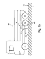
- FIG. 1b shows a vehicle 60a, in which the traction aid 80 is designed in the form of an automatic snow chain 85.
- This vehicle is different from the vehicle of FIG. 1 merely in that the additional snow chains are arranged in the region of the second driven axle 62.
- the sensor 2 is connected to a controller 7, which may be arranged on the sensor 2 or at another location in the vehicle 60.
- the controller 7 serves to evaluate the data detected by the optical sensor 2 and to determine whether the coefficient of friction of the road surface 1a, for example, is below a predetermined value, or whether the traction aid 80 is to be switched on for another reason. If a plurality of traction aids 80 are provided, the controller 7 may also be designed to determine which of the traction aids 80 is being driven.
- the FIG. 2 shows a device 9.
- the device 9 has a surface sensor 2 and a controller 7.
- the surface sensor 2 comprises a light emitter device 10 and at least a first detector device 20.
- a second detector device 30 is further provided.
- the surface sensor 2 may be a commercial surface sensor 2 which is designed for optical detection of the road surface of the road surface 1 a.
- the surface sensor 2 herein also referred to as a sensor 2 for detecting the condition, in particular a condition and the type of surface of a roadway 1 or road surface 1 a, is designed to be mounted on a motor vehicle 60.
- the sensor 2 comprises in a housing 4 three devices, a light emitter device 10, a first detector device 20 and a second detector device 30.
- the light emitter device 10 has a light emitter window or a light emitter opening 18 in the housing 4
- the first detector device 20 has a first detector window or a first detector opening 28 in the housing 4
- the second detector means 30 has a second detector window or a second detector opening 38 in the housing 4.
- the light-emitting aperture 18, the first detector opening 28 and the second detector opening 38 are disposed on the same side 4a of the housing 4 and aligned with the carriageway 1 when the sensor 2 is operatively mounted on a vehicle.
- the sensor 2 is oriented so that the emitted light beam 11 falls approximately perpendicular to the roadway 1 or road surface 1 a, i. the optical axis of the light emitter section 10a or the light emitter axis 11a is substantially perpendicular to the roadway 1 or road surface 1a.
- the road surface may also be snow-covered, icy or dry or have a different nature.
- the light emitting means 10 the first detecting means 20 and the second detecting means 30 are arranged in a row, and the light emitting means 10 is disposed between the first detecting means 20 and the second detecting means 30.
- the light emitter device 10, the first detector device 20 and the second detector device 30 can also be arranged separately from one another and need not be combined in one housing.
- a light source unit 12 is arranged, which is used to emit light of several different wavelengths is designed.
- the light source unit 12 can for this purpose comprise one or more light-emitting diodes (LEDs), laser diodes, another suitable light source or a combination thereof and is suitable for emitting light of several mutually different wavelengths.
- the light source unit 12 may emit light at least at the wavelengths 1300 nm, 1460 nm, and 1550 nm.
- the intended wavelengths can be adapted to the respective application.
- the light source unit 12 is in the in FIG. 2 illustrated example in the direction of the emitted light beam 11, a Lichtménpolarisator or Lichtménpolarisationsfilter 14 downstream, which polarizes the light emitted from the light source unit 12 light in a predetermined direction.
- an emitter optical system 16 is provided in order to align or focus the emitted light along an emitted light beam 11 onto a specific area on the ground or the roadway 1 or the roadway surface 1 a under the vehicle 60.
- the optical axis of the emitter optic 16 may define the optical axis 10a of the light emitter section 10.
- the emitter optic 16 may consist of an emitter lens or comprise a plurality of lenses and / or other optical elements.
- the first detector section 20 comprises a first detector 22, for example one or more photodiodes, designed to detect light of all wavelengths emitted by the light source unit 10.
- the first detector 22 may also include a plurality of juxtaposed photodiodes or one or more opto-electronic devices (e.g., CCD, CMOS).
- a first collection optics 26 and a first polarizer or first polarization filter 24 are arranged.
- the first collection optics 26 may consist of a single first collection lens or may comprise a plurality of lenses and / or further optical elements.
- the polarization direction of the first polarizing filter 24 is perpendicular to that of the light source polarizing filter 14 and thus substantially perpendicular to the predetermined polarization direction. Reflecting reflected light polarized in the predetermined direction is thereby filtered out and only diffusely reflected light reaches the first detector 22.
- the first detector 22 thus serves as a "scatter detector".
- a first axis 20a may substantially correspond to the optical axis of the first collection optics 26 and / or of the first detector section 20 and may be aligned substantially parallel to the emitter axis 10a, which substantially corresponds to the optical axis of the emitter optics 16 and / or the light emitter section 10 ,
- a second detector 32 is arranged in the second detector section 30, which is arranged on the side of the light emitter section 10 opposite the first detector section 20 in the housing 4 of the sensor 2, a second detector 32 is arranged.
- the second detector 32 may also comprise a photodiode which is designed to detect at least light of a wavelength emitted by the light source unit 12. However, the second detector 32 may also include a plurality of juxtaposed photodiodes and configured to detect light of several different wavelengths or wavelength ranges.
- the second detector 32 is associated with a second collection optics 36 to focus the reflected light on the second detector 32 and to detect in this.
- the second collection optics 36 may consist of a single second condenser lens or comprise a plurality of lenses and / or further optical elements.
- the second detector 32 in the FIG. 1 example illustrated no polarizer or polarization filter. Since already the emitted light is polarized, this is not necessary. The second detector thus detects diffusely reflected and specularly reflected light which propagates along the second detector beam path 31 is reflected.
- the second detector 32 may also include a polarizing filter (not shown) whose polarization direction is parallel to that of the emitter polarizer 16 to detect only specularly reflected light in the second photodiode 36.
- a second axis 30a may substantially correspond to the optical axis of the second collection optics 36 and / or the second detector section 30 and may be aligned substantially parallel to the emitter axis 10a, which corresponds substantially to the optical axis of the emitter optics 16 and / or the light emitter section 10.
- the described sensor can be operated in the visible light range, for example at a wavelength of approximately 625 nm, to measure specularly reflected light and diffusely reflected light. From the ratio of the diffusely reflected light measured in the first detector 22 to the specularly reflected light additionally measured in the second detector 32, it is possible to determine the roadway brightness and road surface roughness and thus determine whether the vehicle is on an asphalt or concrete roadway, for example.
- the described sensor can also be used in the infrared range at different wavelengths.
- the first detector 22 and / or the second detector 32 can be used.
- infrared light of wavelength 1460 nm is absorbed particularly well by water, so that light of this wavelength is only slightly reflected back to the first detector 22 and the second detector 32 in the wet road. On dry roads, this wavelength is normally reflected.
- Infrared light of wavelength 1550 nm is well absorbed by ice.
- the reference wavelength which is not significantly absorbed by either ice or water, eg 1300 nm, serves as a reference for evaluation the degree of absorption of the other two wavelengths. Then, the measured intensity ratios at the wavelengths 1550 nm / 1300 nm with the ratio 1460 nm / 1300 nm can be related in a known manner in order to obtain information on water and ice on the road or a dry road.
- the different wavelengths can be transmitted in parallel, but in particular sequentially offset in time. Thus, only light of one wavelength at a time is emitted and detected accordingly. This makes it possible to dispense with a complex spectral analysis or beam splitting.
- the sensor 2 also has an evaluation device 50 with which the data detected or determined by the first detector 22 and the second detector 32 are processed.
- the evaluation device 50 may be arranged outside the housing 4 and may be located, for example, in another location in the vehicle 60.
- the evaluation device 50 may be connected to the first detector 22 and the second detector 32 via a cable or a wireless connection.
- the evaluation device may also include a controller for the light source unit 21 or be connected to a controller.
- the evaluation unit 50 and / or the control can also be arranged on or in the housing 4 or be integrated into it, as with reference to FIGS FIG. 2 shown.
- spectral reflection as well as specular and diffuse reflection can be measured in a short time sequence with a compact and cost-effective design and can be concluded on the basis of roadway type and condition. This results in a better and more accurate information about the nature and the actual condition of the lane 1 or road surface 1a under the vehicle 60. For the measurement, only the one sensor 2 is required.
- the second detector section 30 can be omitted.
- the evaluation device 50 of the sensor 2 is connected to a controller 7.
- the controller 7 serves to evaluate the data of the sensor 2 and to determine whether the coefficient of friction of the road surface 1a is below a predetermined value, or whether a snow-covered or icy road surface 1a has been detected. If a corresponding road surface 1a was detected, the controller 7 can instruct the traction aid 80 to switch on the traction aid 80 and, for example, to activate the automatic snow chains 85 or to relieve the third axle 63.
- the controller 7 may instruct the traction aid 80 to turn off the traction aid 80 and, for example, shut off the snow chains 85 or, if necessary, re-load the third axle 63.
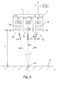
- FIG. 3 shows another example of a device 9.
- FIG. 3 illustrated and described features, depending on the application with respect to the FIG. 2 illustrated and described features are combined or replaced.
- the Indian FIG. 3 shown sensor 2 corresponds to that with respect to the FIG. 2 described sensor with the difference that no Lichtierinpolarisator is provided.
- the emitted light beam 110 is not polarized in this case.
- a second polarization filter 34 is arranged in the beam path in front of the second detector 32.
- the polarization direction of the second polarization filter 34 is substantially perpendicular to the polarization direction of the first polarization filter 24. All other elements of the sensor 2 can those of the reference to the FIG. 1 represented sensor correspond.
- the first axis 20b which may correspond to the optical axis of the first collection optics 26 and / or the entire first detector portion 20, is oriented at an angle ⁇ to the emitter axis 10a, the angle ⁇ being at most about 10 °.
- the second axis 30b which may correspond to the optical axis of the second collection optics 36 and / or the entire second detector portion 30, may be oriented at an angle ⁇ to the emitter axis 10a, the angle ⁇ also being at most about 10 °.
- the intersection 40 of the emitter axis 10a with the first axis 20b and / or the second axis 30b may lie on the road surface 1 a or lie at a distance of up to 50cm from the road surface 1 a.
- the polarization directions of the light source polarizing filter 14 and the second polarizing filter 34 are then aligned parallel to one another.
- the polarization directions of the light source polarizing filter 14 and the second polarizing filter 34 of the second detector 32 are arranged substantially perpendicular to the polarization direction of the first polarizer 24.
- the evaluation device 50 is arranged inside the housing 4 of the sensor 2 or integrated into the housing 2. It understands itself, that the evaluation unit also, as in FIG. 1 shown, may be provided outside of the sensor 2.
- the sensor 2 and in particular the emitter optics 16 and the first collection optics 26, or optionally also the second collection optics 36, can be designed to be arranged above the roadway surface 1a at a certain height or a certain height range.
- the sensor 2 may be designed to be arranged at a height h or a distance of about 10 cm to about 1 m from the road surface 1 a, wherein the distance can be adapted to a particular application.
- the height h may be in the range of about 10 cm to 40 cm.
- the height h may be about 30 cm to about 100 cm, in particular in a range of 50 cm to 80 cm.
- the controller 7 is also disposed within the housing 4 of the sensor 2.
- the controller 7 may be connected to the evaluation device 50 of the sensor 2 or integrated into it.
- the FIG. 4 shows an example of a method for controlling a traction aid.
- the method comprises the step of detecting information about a road surface or the condition of a road surface 1a.
- Detecting the information 100 about the nature of the road surface 1a includes emitting light 110 of at least one wavelength, preferably at least three mutually different wavelengths in the infrared region, and detecting 120 light reflected on the road surface 1a.
- the light of the different wavelengths can be staggered in time, for example, modulated with different frequency or phase-shifted with the same frequency transmitted and detected accordingly. The allows to use only one detector for several wavelengths and possibly the background radiation with light sources switched off.
- step 150 From the ratio of the light intensities of the reflected light of the different wavelengths or the ratio of diffusely reflected and specularly reflected light, information about the condition of the roadway surface 1a is then determined in step 150, that is, whether the roadway 1a is dry, wet, icy, snowy or another condition. In this step, too, the thickness of a water film or the thickness of an ice sheet on the road surface 1a can be determined.
- step 200 it may be determined in step 200 if necessary with the addition of further parameters, such as the vehicle speed or a slope at which the vehicle is currently located, as to whether a traction aid 80 should be activated.
- the slope can be detected for example with a tilt sensor. If it is determined in step 200 that a traction aid is to be activated, the traction aid 80 is activated in step 300.
- step 300 the traction aid may be deactivated.
- the person skilled in the art will also consider other than the specified wavelengths in order to adapt the measurement results to different requirements. It is understood that the indicated wavelengths are not limited to the exact values, but may include a wavelength range containing the indicated discrete wavelengths.
Landscapes
- Engineering & Computer Science (AREA)
- Physics & Mathematics (AREA)
- Mechanical Engineering (AREA)
- General Physics & Mathematics (AREA)
- Biochemistry (AREA)
- Spectroscopy & Molecular Physics (AREA)
- Health & Medical Sciences (AREA)
- Life Sciences & Earth Sciences (AREA)
- Chemical & Material Sciences (AREA)
- Analytical Chemistry (AREA)
- Pathology (AREA)
- General Health & Medical Sciences (AREA)
- Automation & Control Theory (AREA)
- Immunology (AREA)
- Mathematical Physics (AREA)
- Transportation (AREA)
- Investigating Or Analysing Materials By Optical Means (AREA)
Abstract
Description
Die vorliegende Beschreibung bezieht sich auf Traktionshilfen für Fahrzeuge. Insbesondere bezieht sich die vorliegende Beschreibung auf ein Verfahren und eine Vorrichtung zur Steuerung von automatischen Traktionshilfen bei Nutzfahrzeugen.The present description relates to traction aids for vehicles. More particularly, the present description relates to a method and apparatus for controlling automatic traction aids on commercial vehicles.
Insbesondere für Nutzfahrzeuge sind automatische Traktionshilfen bekannt, welche es dem Fahrer erlauben bei unsicheren Straßenverhältnissen die Traktionshilfe zuzuschalten, wodurch das manuelle und zeitaufwändige Anlegen von Schneeketten vermieden wird. Als Traktionshilfen sind beispielsweise automatische Schneeketten bekannt, welche bei Nutzfahrzeugen, insbesondere bei Lastkraftwagen an den Antriebsachsen angebracht sein können und mittels eines Schleudermechanismus zwischen Fahrbahn und Reifen ausgebracht werden um so die Traktion auf einem rutschigen Untergrund, wie einer verschneiten oder vereisten Fahrbahn zu erhöhen. Diese bekannten automatischen Schneeketten werden manuell von dem Fahrer bedient.In particular, for commercial vehicles automatic traction aids are known, which allow the driver to turn on in uncertain road conditions, the traction aid, whereby the manual and time-consuming application of snow chains is avoided. As traction aids, for example, automatic snow chains are known, which may be attached to commercial vehicles, especially in trucks on the drive axles and are applied by means of a sling mechanism between the road and tires to increase the traction on a slippery surface, such as a snowy or icy road. These known automatic snow chains are operated manually by the driver.
Als Traktionshilfe für Nutzfahrzeuge ist es auch bekannt, bei mehrachsigen Fahrzeugen, welche beispielsweise über eine dritte Hilfsachse verfügen, diese Hilfsachsen kurzfristig zu entlasten bzw. anzuheben und somit die Achslast auf die verbleibenden Achsen und insbesondere auf angetriebene Achsen zu erhöhen. Durch die erhöhte Achslast kann auch eine erhöhte Traktion bei rutschigen Fahrbahnverhältnissen erreicht werden. Dabei ist es möglich die offiziell zulässige maximale Achslast kurzfristig zu überschreiten, um die nötige Traktion beispielsweise als Anfahrhilfe zu erreichen.As a traction aid for commercial vehicles, it is also known in multiaxial vehicles, which have, for example, a third auxiliary axis, to temporarily relieve or increase these auxiliary axes and thus increase the axle load on the remaining axes and in particular on driven axles. Due to the increased axle load and increased traction in slippery road conditions can be achieved. It is possible to exceed the officially permitted maximum axle load in the short term in order to achieve the necessary traction, for example, as traction help.
Eine solche Achslastregelung ist beispielsweise aus den Dokumenten
Um die Achslastverlagerung beziehungsweise Achslastentlastung der Hilfsachse zur Traktionshilfe auszuführen, muss der Fahrer zunächst den rutschigen beziehungsweise gefährlichen Untergrund erkennen, und dann manuell die entsprechende Traktionshilfe aktivieren.In order to carry out the Achslastverlagerung or axle load relief of the auxiliary axle for traction help, the driver must first recognize the slippery or dangerous surface, and then manually activate the appropriate traction aid.
Es ist eine Aufgabe der vorliegenden Erfindung die Nachteile des Standes der Technik zu überwinden, insbesondere ist die Erkennung durch den Fahrer und die manuelle Betätigung bei Irrtum in der einen als auch der anderen fehlerhaften Annahme Risikobehaftet, da in beiden Fällen ein instabiles Fahrzeugverhalten resultieren kann.It is an object of the present invention to overcome the disadvantages of the prior art, in particular the recognition by the driver and the manual operation in case of error in the one and the other erroneous assumption is risky, since in both cases, an unstable vehicle behavior can result.
Zur Lösung der Aufgabe schlägt die Erfindung ein Verfahren gemäß Anspruch 1 und eine Vorrichtung gemäß Anspruch 8 zur Steuerung einer Traktionshilfe eines Fahrzeugs vor.To achieve the object, the invention proposes a method according to
Ferner bezieht sich die Erfindung auf ein Fahrzeug, welches mit einer entsprechenden Vorrichtung ausgestattet ist und in welchem das erfindungsgemäße Verfahren ausgeführt wird.Furthermore, the invention relates to a vehicle which is equipped with a corresponding device and in which the method according to the invention is carried out.
Das erfindungsgemäße Verfahren zur Steuerung einer Traktionshilfe eines Fahrzeugs umfasst das Aussenden von Licht von zumindest einer Wellenlänge auf eine Fahrbahnoberfläche unter dem Fahrzeug, ein Detektieren von an der Fahrbahnoberfläche reflektiertem Licht der zumindest einen Wellenlänge, ein Ermitteln zumindest einer Information über die Beschaffenheit der Fahrbahnoberfläche anhand des detektierten reflektierten Lichts der zumindest einen Wellenlänge, ein Ermitteln anhand der zumindest einen Information, ob der Reibwert der Fahrbahnoberfläche eine Traktionshilfe erforderlich macht und/oder ob die Traktionshilfe nicht mehr erforderlich ist, ein entsprechendes Steuern der Traktionshilfe, wenn ermittelt wurde ob die Traktionshilfe erforderlich ist oder nicht mehr erforderlich ist.The inventive method for controlling a traction aid of a vehicle comprises emitting light of at least one wavelength on a road surface under the vehicle, detecting light of the at least one wavelength reflected on the road surface, determining at least one information about the nature of the road surface using the detected reflected light of the at least one wavelength, a determination based on the at least one information, whether the coefficient of friction of the road surface requires a traction aid and / or whether the traction aid is no longer required, a corresponding Control the traction aid when it has been determined whether the traction aid is required or no longer required.
Die Vorrichtung zur Steuerung einer Traktionshilfe eines Fahrzeugs umfasst einen optischen Oberflächensensor zur Ermittlung zumindest einer Information über die Beschaffenheit einer Fahrbahnoberfläche und eine Steuerung, welche mit dem optischen Oberflächensensor und der Traktionshilfe verbunden ist und anhand der zumindest einen Information über die Fahrbahnoberfläche die Traktionshilfe steuert.The device for controlling a traction aid of a vehicle comprises an optical surface sensor for detecting at least one information about the nature of a road surface and a controller which is connected to the optical surface sensor and the traction aid and controls the traction aid based on the at least one information about the road surface.
Mittels der optischen Ermittlung der Beschaffenheit der Fahrbahnoberfläche, beziehungsweise mittels dem Ermitteln von zumindest einer Information über die Fahrbahnbeschaffenheit kann automatisch, zuverlässig und berührungslos ermittelt werden, ob die Fahrbahnoberfläche nass, vereist, schneebedeckt und/oder trocken ist, das heißt in welchem Zustand die Fahrbahnoberfläche ist. Ferner kann ermittelt werden, welcher Art die Fahrbahn ist, das heißt ob es sich bei der Fahrbahn um eine Asphalt, eine Betonfahrbahn oder eine andere Fahrbahnoberfläche handelt. Der optische Sensor ohne direkten Fahrbahnkontakt ist weniger störanfällig, insbesondere gegenüber Vereisung und aufgewirbelten Schnee, da er über keine mechanischen Teil verfügt. Ferner kann der optische Sensor geschützt an einer beliebigen stelle im unteren Bereich des Fahrzeugsangeordnet werden.By means of the optical determination of the condition of the road surface, or by determining at least one information about the road condition can be determined automatically, reliably and contactless, whether the road surface is wet, icy, snowy and / or dry, that is, in which state the road surface is. Furthermore, it can be determined which type the roadway is, that is, whether the roadway is an asphalt, a concrete carriageway or another road surface. The optical sensor without direct road contact is less prone to failure, especially against icing and whirling snow, as it has no mechanical part. Further, the optical sensor can be protected at any location in the lower area of the vehicle.
Auch kann mit dem optischen Sensor ermittelt werden, ob es sich bei einer vereisten Fahrbahn um eine bestimmte Eisdicke oder bei einem Wasserfilm um eine bestimmte Wasserfilmdicke handelt. Der optische Sensor liefert daher genauere Informationen über die Beschaffenheit, insbesondere über den Zustand der Fahrbahnoberfläche, als z.B. mechanische Sensoren.It can also be determined with the optical sensor, whether it is an icy roadway to a certain thickness of ice or a water film to a certain water film thickness. The optical sensor therefore provides more accurate information about the condition, especially about the condition of the road surface, e.g. mechanical sensors.
Aus dieser Information über die Beschaffenheit der Fahrbahn kann auf einen Reibwert der Fahrbahnoberfläche geschlossen werden, zum Beispiel, wenn dieser durch Eis oder Schnee auf der Fahrbahn verringert ist. Wird ein entsprechend verringerter Reibwert ermittelt, wird die Traktionshilfe automatisch zugeschaltet. Es ist auch möglich, das vor der Zuschaltung der Traktionshilfe weitere Parameter, wie die Fahrzeuggeschwindigkeit, das vorhanden sein einer Steigung oder anderes abgefragt wird.From this information about the condition of the roadway, it is possible to deduce a coefficient of friction of the road surface, for example when it is reduced by ice or snow on the road. If a correspondingly reduced coefficient of friction is determined, the traction aid is automatically activated. It is also possible that before the connection of the traction help further parameters, such as the vehicle speed, the presence of a slope or other is queried.
Die Vorrichtung und das Verfahren erlauben es, die Traktionshilfe zuzuschalten, sobald eine Fahrbahnoberfläche mit einem geringen Reibwert erkannt wurde, und somit gegebenenfalls bevor eine gefährliche Situation für das Fahrzeug entstehen kann.The device and the method make it possible to switch on the traction aid as soon as a road surface with a low coefficient of friction has been detected, and thus possibly before a dangerous situation can arise for the vehicle.
Mit dem Verfahren und der Vorrichtung kann vorteilhaft eine Traktionshilfe bereits bei stehendem Fahrzeug automatisch zugeschaltet werden, da der optische Oberflächensensor, beziehungsweise das optische Verfahren die rutschige Fahrbahnoberfläche beziehungsweise den verminderten Reibwert bereits unabhängig von einer Fahrzeugbewegung erkennen kann.Advantageously, with the method and the device, a traction aid can be automatically activated even when the vehicle is stationary, since the optical surface sensor or the optical method can already detect the slippery road surface or the reduced coefficient of friction independently of vehicle movement.
Das Verfahren und die Vorrichtung kann auch verwendet werden, um eine Traktionshilfe abzuschalten, wenn dies der Zustand beziehungsweise die Beschaffenheit der Fahrbahnoberfläche nicht mehr erforderlich macht. Erkennt der optische Oberflächensensor beispielsweise, dass die Fahrbahn nicht mehr vereist und/oder nicht mehr schneebedeckt ist, sondern beispielsweise nass oder trocken ist, so kann die Traktionshilfe automatisch abgeschaltet werden. Ein unnötiger Verschleiß kann verhindert werden. Sollte sich der Fahrbahnzustand wieder verschlechtern und eventuell wieder eine vereiste oder verschneite Fahrbahnoberfläche erkannt werden, so kann die Traktionshilfe wieder zugeschaltet werden.The method and apparatus may also be used to turn off a traction aid when the condition or condition of the road surface makes it unnecessary. If the optical surface sensor recognizes, for example, that the road is no longer icy and / or is no longer covered in snow, but is, for example, wet or dry, the traction aid can be automatically switched off. An unnecessary wear can be prevented. Should the road condition deteriorate again and possibly an icy or snowy road surface be recognized again, then the traction aid can be switched on again.
Die Traktionshilfe kann automatische Schneeketten umfassen, wie sie an sich dem Fachmann bekannt sind. Die Traktionshilfe kann auch eine Achsentlastung umfassen, wie sie dem Fachmann ebenfalls aus dem Stand der Technik bekannt ist. Die Traktionshilfe kann auch ein Abbremsen der angetriebenen Räder umfassen. Die Vorrichtung kann auch eine Kombination aus den genannten Traktionshilfen umfassen.The traction aid may comprise automatic snow chains, as they are known in the art. The traction aid may also include an axle relief, as is known in the art also from the prior art. The traction aid may also include braking the driven wheels. The device may also comprise a combination of said traction aids.
Mit dem Verfahren und der Vorrichtung kann vorteilhaft eine Traktionshilfe bereits bei stehendem Fahrzeug automatisch zugeschaltet werden, da der optische Oberflächensensor beziehungsweise das optische Verfahren die rutschige Fahrbahnoberfläche beziehungsweise den verminderten Reibwert bereits vor dem Anfahren erkennen kann.Advantageously, with the method and the device, it is possible to automatically switch on a traction aid even when the vehicle is stationary, since the optical surface sensor or the optical method can already detect the slippery road surface or the reduced coefficient of friction before starting.
Der optische Oberflächensensor der Vorrichtung kann über eine Lichtquelleneinheit zum Aussenden von Licht von zumindest einer Wellenlänge auf den Untergrund und zumindest einen Detektor umfassen, um von dem Untergrund reflektiertes Licht zu detektieren.The optical surface sensor of the device may include a light source unit for emitting light of at least one wavelength to the ground and at least one detector for detecting light reflected from the ground.
Der Oberflächensensor kann neben dem ersten Detektor einen zweiten Detektor umfassen, wobei der erste Detektor zum Erfassen von diffus reflektiertem Licht und der zweite Detektor zum Erfassen von spiegelnd reflektiertem Licht geeignet sind. Es können zumindest zwei Polarisatoren vorgesehen sein, wobei ein erster Polarisator mit einer ersten Polarisationseinrichtung dem ersten Detektor zugeordnet ist. Der Lichtquelleneinheit kann ein Lichtquellenpolarisator und/oder dem zweiten Detektor kann ein zweiter Polarisator zugeordnet sein, dessen Polarisierungsrichtung(en) im Wesentlichen senkrecht zu der ersten Polarisierungsrichtung des ersten Polarisators ausgerichtet ist/sind. Sind zumindest zwei Polarisatoren bzw. Polarisationsfilter vorgesehen, ist der erste Polarisator an dem ersten Detektor angeordnet, welcher nur Lichtwellen in der ersten Polarisationsrichtung zu dem ersten Detektor durchlässt. Ist ein Lichtquellenpolarisator an der Lichtquelleneinheit vorgesehen, ist dessen Polarisationsrichtung im Wesentlichen senkrecht zu der ersten Polarisationsrichtung des ersten Polarisators angeordnet, und das von dem Sensor ausgesandte Licht ist in einer Richtung im Wesentlichen senkrecht zu der ersten Polarisationsrichtung polarisiert, so dass an dem ersten Detektor polarisiertes, spiegelnd reflektiertes Licht herausgefiltert und nur diffus reflektiertes Licht detektiert wird. Ein ähnlicher Effekt kann erreicht werden, wenn ein zweiter Polarisator vor dem zweiten Detektor angeordnet ist, dessen Polarisationsrichtung im Wesentlichen senkrecht zu der ersten Polarisationsrichtung ausgerichtet ist. Der zweite Polarisator kann alternativ oder zusätzlich zu dem Lichtquellenpolarisator verwendet werden. Es kann auch vorgesehen sein, in der Lichtquelleneinheit bereits polarisiertes Licht zu erzeugenThe surface sensor may comprise a second detector in addition to the first detector, wherein the first detector for detecting diffusely reflected light and the second detector for detecting specularly reflected light are suitable. At least two polarizers can be provided, wherein a first polarizer having a first polarization device is assigned to the first detector. The light source unit may be a Lichtquellenpolarisator and / or the second detector may be associated with a second polarizer whose polarization direction (s) is oriented substantially perpendicular to the first polarization direction of the first polarizer / are. If at least two polarizers or polarization filters are provided, the first polarizer is arranged on the first detector, which transmits only light waves in the first polarization direction to the first detector. When a light source polarizer is provided on the light source unit, its polarization direction is substantially perpendicular to the first polarization direction of the first polarizer, and the light emitted from the sensor is polarized in a direction substantially perpendicular to the first polarization direction, so that polarized at the first detector , Reflected reflected light filtered out and only diffuse reflected light is detected. A similar effect can be achieved if a second polarizer is arranged in front of the second detector whose polarization direction is oriented substantially perpendicular to the first polarization direction. The second polarizer may be used alternatively or in addition to the light source polarizer. It can also be provided to generate already polarized light in the light source unit
Die Lichtquelleneinheit kann zum Aussenden von Licht von zumindest zwei voneinander verschiedenen Wellenlängen oder zum Aussenden von mehreren Wellenlängen auf den Untergrund bzw. die Fahrbahnoberfläche ausgelegt sein. Dazu kann die Lichtquelleneinheit beispielsweise mehrere Lichtquellen umfassen. Die Verwendung mindestens zweier, vorzugsweise drei von einander verschiedener Wellenlängen erlaubt es, den Sensor in spektraler Weise zu betreiben. Durch die Verwendung von Wellenlängen, welche z.B. von Eis oder Wasser besonders gut absorbiert werden, können Eis bzw. Wasser auf der Fahrbahn bzw. Fahrbahnoberfläche erkannt werden, wenn das reflektierte Licht der vom Wasser bzw. Eis absorbierten Wellenlänge mit dem einer Referenzwellenlänge verglichen wird. Es ist somit möglich, die Prinzipien der Spektralanalyse und der Diffus- und Spiegelndreflexion in nur einem Gerät, bzw. einem einzigen Gehäuse auszuführen. Die zumindest eine Lichtquelleneinheit, der erste Detektor und gegebenenfalls der zweite Detektor können dazu in einem gemeinsamen einzigen und/oder einstückigen Gehäuse beispielsweise unmittelbar nebeneinander angeordnet sein.The light source unit can be designed to emit light of at least two mutually different wavelengths or to emit a plurality of wavelengths onto the ground or the road surface. For this purpose, the light source unit may for example comprise a plurality of light sources. The use of at least two, preferably three, of different wavelengths makes it possible to operate the sensor in a spectral manner. By using wavelengths which are e.g. ice or water can be detected on the road surface when the reflected light of the wavelength absorbed by the water or ice is compared with that of a reference wavelength. It is thus possible to implement the principles of spectral analysis and diffuse and specular reflection in a single device or housing. The at least one light source unit, the first detector and possibly the second detector can be arranged for this purpose in a common single and / or one-piece housing, for example directly next to one another.
Es kann Licht in zumindest drei voneinander verschiedenen Wellenlängen im Infrarotbereich verwendet werden. Die Lichtquelleneinheit kann dazu mehrere Lichtquellen umfassen. Z.B. kann die Lichtquelleneinheit dazu ausgelegt sein, Infrarotlicht der Wellenlängen 1300 nm, 1460 nm und 1550 nm auszusenden. Während Licht der Wellenlänge 1460 nm besonders gut von Wasser absorbiert wird, wird Licht der Wellenlänge 1550 nm gut von Eis absorbiert. Licht im Bereich von ungefähr 1300 nm kann dann als Referenzwellenlänge verwendet werden. Es können jedoch auch andere Wellenlängen verwendet werden. Insbesondere für die Referenzwellenlänge kann jede andere Wellenlänge verwendet werden, welche weder von Eis noch Wasser nennenswert absorbiert wird. Als wassersensitive Wellenlänge kann auch jede andere Wellenlänge verwendet werden, welche in Wasser erhöht absorbiert wird. Genauso kann als eissensitive Wellenlänge jede Wellenlänge gewählt werden, welche in Eis erhöht absorbiert wird. Andere interessante Wellenlängen umfassen z.B. 1190, 1040, 970, 880 und 810 nm im Infrarotbereich, sowie die sichtbaren Wellenlängen 625, 530 und 470 nm.It is possible to use light in at least three mutually different wavelengths in the infrared range. The light source unit may for this purpose comprise a plurality of light sources. For example, the light source unit may be configured to emit infrared light of the wavelengths 1300 nm, 1460 nm and 1550 nm. While light of wavelength 1460 nm is particularly well absorbed by water, light of wavelength 1550 nm is well absorbed by ice. Light in the range of about 1300 nm can then be used as the reference wavelength. However, other wavelengths may be used. In particular, for the reference wavelength, any other wavelength can be used which is not significantly absorbed by neither ice nor water. As a water-sensitive wavelength, any other wavelength can be used be absorbed, which is increased in water. In the same way, each wave length can be chosen as the pseudo-wavelength, which is absorbed in ice. Other interesting wavelengths include, for example, 1190, 1040, 970, 880 and 810 nm in the infrared range, as well as the visible wavelengths 625, 530 and 470 nm.
Die Lichtquelleneinheit kann dazu ausgelegt sein, Licht genau drei verschiedener Wellenlängen auszusenden. Dazu kann die Lichtquelleneinheit drei Lichtquellen, eine Lichtquelle für jede Wellenlänge aufweisen. Es werden nur die drei Wellenlängen verwendet, um sowohl spektral als auch spiegelnd/diffus reflektiertes Licht zu erfassen, um sowohl die Fahrbahnbeschaffenheit als auch die Art der Fahrbahn zu ermitteln bzw. zu erkennen. Jede der Lichtquellen kann einzeln ansteuerbar und unabhängig von den anderen an- und abschaltbar sein bzw. in der Intensität regulierbar sein.The light source unit may be configured to emit light of exactly three different wavelengths. For this purpose, the light source unit can have three light sources, one light source for each wavelength. Only the three wavelengths are used to detect both spectral and specular / diffuse reflected light to detect both the road condition and the type of roadway. Each of the light sources can be controlled individually and switched on and off independently of the other or be adjustable in intensity.
Darüber hinaus können auch mehr als die oben genannten zwei oder drei voneinander verschiedenen Wellenlängen verwendet werden. Beispielsweise kann die Wellenlänge 625 nm auch zur Messung des diffus und spiegelnd reflektierten Lichts verwendet werden.In addition, more than the above two or three different wavelengths may be used. For example, the wavelength 625 nm can also be used to measure the diffused and specularly reflected light.
Es kann weiterhin vorgesehen sein, das ausgesendete Licht in der Intensität bzw. Amplitude zu modulieren. Das Modulieren der Intensität oder Amplitude kann durch An- und Ausschalten aller oder einzelner Lichtquellen der Lichtquelleneinheit erfolgen. Das Modulieren der Intensität bzw. das An- und Abschalten kann für jede Wellenlänge der Lichtquelleneinheit oder für jede Lichtquelle der Lichtquelleneinheit separat erfolgen. Beispielsweise kann das Modulieren der Amplitude oder Intensität bzw. das An- und Abschalten für jede Wellenlänge mit der gleichen Frequenz, jedoch phasenverschoben und/oder mit unterschiedlichen Frequenzen erfolgen. Dadurch kann beispielsweise erreicht werden, dass das Licht unterschiedlicher Wellenlängen zeitlich versetzt oder sequentiell ausgesandt wird. Z.B. kann vorgesehen sein, Licht einer ersten Wellenlänge für ein bestimmtes Zeitintervall auszusenden, dann das Licht der ersten Wellenlänge abzuschalten und eine zweite Wellenlänge einzuschalten usw. In den Detektoren wird dann jeweils Licht von nur einer Wellelänge detektiert. Dadurch kann eine spektrale Analyse oder Aufspaltung des einfallenden Lichts an den Detektoren vermieden werden. Es sind auch Mischformen verschiedener Modulationstechniken anwendbar, insbesondere frequenz- und amplitudenmodulierte optische Signalzüge mit oder ohne Unterbrechungen.It may further be provided to modulate the emitted light in intensity or amplitude. The modulation of the intensity or amplitude can be done by turning on and off all or individual light sources of the light source unit. The modulation of the intensity or the switching on and off can be carried out separately for each wavelength of the light source unit or for each light source of the light source unit. For example, the modulation of the amplitude or intensity or the switching on and off for each wavelength with the same frequency, but out of phase and / or with different frequencies. As a result, it can be achieved, for example, that the light of different wavelengths is transmitted offset in time or sequentially. For example, it may be provided to emit light of a first wavelength for a specific time interval, then the light of the first wavelength turn off and turn on a second wavelength, etc. In the detectors then each light of only one wavelength is detected. As a result, a spectral analysis or splitting of the incident light at the detectors can be avoided. Mixed forms of different modulation techniques are also applicable, in particular frequency and amplitude modulated optical signal trains with or without interruptions.
Die vorliegende Erfindung erlaubt es daher auch, einfache Detektoren als ersten oder zweiten Detektor zu verwenden. Beispielsweise können Photodioden verwendet werden. Der erste Detektor und der zweite Detektor können jeweils eine oder mehrere Photodioden umfassen. Zumindest der erste Detektor kann dazu ausgelegt sein, Licht aller von der Lichtquelleneinheit ausgesendeten Wellenlängen zu erfassen. Der Detektor kann auch alternativ oder ergänzend einen optoelektronischen Chip (z.B. CCD) oder eine andere optische Aufnahmeeinrichtung umfassen.The present invention therefore also makes it possible to use simple detectors as the first or second detector. For example, photodiodes can be used. The first detector and the second detector may each comprise one or more photodiodes. At least the first detector may be configured to detect light of all wavelengths emitted by the light source unit. The detector may also alternatively or additionally comprise an optoelectronic chip (e.g., CCD) or other optical pickup device.
Der erste und der zweite Detektor können zur Erfassung bzw. zur Ermittlung von spiegelnd reflektiertem und diffus reflektiertem Licht verwendet werden. Zudem kann zumindest einer aus dem ersten und dem zweiten Detektor auch für die spektrale Ermittlung verwendet werden. Zumindest dieser Detektor ist dann dazu ausgelegt, Licht mehrerer Wellenlängen zu detektieren. In diesem Beispiel verfügt der Sensor über genau den ersten Detektor und den zweiten Detektor und es sind keine weiteren Detektoren vorgesehen.The first and second detectors can be used to detect or detect specularly reflected and diffusely reflected light. In addition, at least one of the first and the second detector can also be used for the spectral determination. At least this detector is then designed to detect light of several wavelengths. In this example, the sensor has exactly the first detector and the second detector and no further detectors are provided.
Der Oberflächensensor kann ferner eine Auswerteinrichtung umfassen, welche eine Information über die Beschaffenheit der Fahrbahnoberfläche bzw. des Untergrunds ausgibt.The surface sensor may further comprise an evaluation device which outputs information about the nature of the road surface or the ground.
Der Oberflächensensor kann zur Einstellung einer vorhandenen Traktionshilfe verwendet werden.The surface sensor can be used to adjust an existing traction aid.
Die erfindungsgemäße Vorrichtung ist zur Anbringung an einem vorhandenen Fahrzeug mit Traktionshilfe geeignet. Die Vorrichtung kann auch in Kombination mit einer Traktionshilfe zur Nachrüstung an einem Fahrzeug angeboten werden.The device according to the invention is suitable for attachment to an existing vehicle with traction aid. The device may also be offered in combination with a traction aid for retrofitting to a vehicle.
Die Vorrichtung und das Verfahren können mit Nutzfahrzeugen, wie Lastkraftwagen oder Omnibussen zur Personenbeförderung verwendet werden. Die Vorrichtung und das Verfahren können aber gleichwohl mit jedem anderen Fahrzeug verwendet werden, an dem eine zuschaltbare Traktionshilfe vorgesehen ist.The apparatus and method can be used with commercial vehicles, such as trucks or buses for passenger transport. However, the device and the method can nevertheless be used with any other vehicle on which a shiftable traction aid is provided.
Im Folgenden werden weitere Einzelheiten und Beispiele der Erfindung lediglich beispielhaft und nicht einschränkend mit Bezug auf die beiliegenden Figuren angeben, welche zeigen:
-
Figur 1a -
Figur 1b ein zweites Beispiel eines Fahrzeugs mit einer erfindungsgemäßen Vorrichtung; -
Figur 2 -
Figur 3 ein zweites Beispiel einer Vorrichtung gemäße der vorliegenden Beschreibung; und -
Figur 4
-
FIG. 1a a first example of a vehicle with a device according to the invention; -
FIG. 1b a second example of a vehicle with a device according to the invention; -
FIG. 2 a first example of a device according to the present description; -
FIG. 3 a second example of a device according to the present description; and -
FIG. 4 schematically a method according to the invention.
Im dargestellten Beispiel hat das Fahrzeug 60 eine lenkbare Vorderachse 61, eine angetriebene zweite Achse 62 und eine nachlaufende und entlastbare dritte Achse 63. Die dritte Achse 63 dient dazu einen Teil der Last aufzunehmen, beispielsweise wenn das Fahrzeug 60 beladen ist und so im normalen Fahrbetrieb die Achslast auf die zweite Achse 62 zu verringern. Um insbesondere die Reifen der dritten Achse 63 nicht unnötig zu verschleißen ist es seit langem bekannt die dritte Achse 63 anzuheben, wenn das Fahrzeug 60 nicht beladen ist und die zulässige Gesamtachslast der zweiten Achse 62 somit nicht überschritten wird. Im dargestellten Beispiel ist die dritte Achse 63 angehoben bzw. entlastet dargestellt. Die dritte Achse 63 kann auch entlastet beziehungsweise angehoben werden, um die Traktion der zweiten Achse 62 zumindest kurzfristig zu erhöhen. In diesem Fall kann die zulässige Achslast der zweiten Achse 62 auch zumindest kurzfristig überschritten werden. Somit stellt die entlastbare dritte Achse 63 eine Traktionshilfe 80 darIn the illustrated example, the
Im dargestellten Beispiel ist die entlastbare dritte Achse 63 hinter der angetriebenen zweiten Achse 62 dargestellt. Es ist jedoch genauso möglich, dass die entlastbare dritte Achse 63 in Fahrtrichtung vor der angetriebenen zweiten Achse 62 angeordnet ist.In the illustrated example, the unloadable
In der
Der Sensor 2 ist mit einer Steuerung 7 verbunden, welche an dem Sensor 2 oder an einer anderen Stelle im Fahrzeug 60 angeordnet sein kann. Die Steuerung 7 dient dazu, die von dem optischen Sensor 2 erfassten Daten auszuwerten und zu bestimmen, ob der Reibwert der Fahrbahnoberfläche 1a beispielsweise unter einem vorbestimmten Wert liegt, oder ob aus einem anderen Grund die Traktionshilfe 80 zugeschaltet werden soll. Sind mehrere Traktionshilfen 80 vorgesehen, kann die Steuerung 7 auch dazu ausgelegt sein, zu bestimmen, welche der Traktionshilfen 80 angesteuert wird.The
Die
Der Oberflächensensor 2, hierein auch als Sensors 2 zur Erkennung der Beschaffenheit, insbesondere eines Zustands und der Art der Oberfläche einer Fahrbahn 1 bzw. Fahrbahnoberfläche 1 a bezeichnet, ist dazu ausgelegt, an einem Kraftfahrzeug 60 angebracht zu werden.The
Der Sensor 2 umfasst in einem Gehäuse 4 drei Einrichtungen, eine Lichtemittereinrichtung 10, eine erste Detektoreinrichtung 20 und eine zweite Detektoreinrichtung 30. Der Lichtemittereinrichtung 10 weist ein Lichtemitterfenster oder eine Lichtemitteröffnung 18 in dem Gehäuse 4 auf, die erste Detektoreinrichtung 20 weist ein erstes Detektorfenster oder eine erste Detektoröffnung 28 in dem Gehäuse 4 auf und die zweite Detektoreinrichtung 30 weist ein zweites Detektorfenster oder eine zweite Detektoröffnung 38 in dem Gehäuse 4 auf. Die Lichtemitteröffnung 18, die erste Detektoröffnung 28 und die zweite Detektoröffnung 38 sind an der gleichen Seite 4a des Gehäuses 4 angeordnet und zu der Fahrbahn 1 hin ausgerichtet, wenn der Sensor 2 betriebsbereit an einem Fahrzeug montiert ist. Der Sensor 2 ist so ausgerichtet, dass der ausgesendete Lichtstrahl 11 ungefähr senkrecht auf die Fahrbahn 1 bzw. Fahrbahnoberfläche 1 a fällt, d.h. die optische Achse des Lichtemitterabschnitts 10a, bzw. die Lichtemitterachse 11a steht im Wesentlichen senkrecht zu der Fahrbahn 1 bzw. Fahrbahnoberfläche 1a. Im dargestellten Beispiel befindet sich ein Wasserfilm 71 der Dicke d1 auf der Fahrbahnoberfläche 1a. Die Fahrbahnoberfläche kann jedoch auch schneebedeckt, vereist oder trocken sein oder eine andere Beschaffenheit haben.The
In dem in den
Die Lichtemittereinrichtung 10, die erste Detektoreinrichtung 20 und die zweite Detektoreinrichtung 30 können jedoch auch getrennt voneinander angeordnet sein und müssen nicht in einem Gehäuse zusammengefasst sein.However, the
In der Lichtemittereinrichtung 10 ist eine Lichtquelleneinheit 12 angeordnet, welche zur Aussendung von Licht mehrerer unterschiedlicher Wellenlängen ausgelegt ist. Die Lichtquelleneinheit 12 kann dazu eine oder mehrere Leuchtdioden (LEDs), Laserdioden, eine andere geeignete Lichtquelle oder eine Kombination daraus umfassen und ist dazu geeignet, Licht mehrerer voneinander verschiedener Wellenlängen auszusenden. Beispielsweise kann die Lichtquelleneinheit 12 Licht zumindest mit den Wellenlängen 1300 nm, 1460 nm und 1550 nm aussenden. Die vorgesehenen Wellenlängen können jedoch dem jeweiligen Einsatzzweck angepasst werden.In the
Der Lichtquelleneinheit 12 ist im in der
Ferner ist eine Emitteroptik 16 vorgesehen, um das ausgesendete Licht entlang eines emittierten Lichtstrahls 11 auf einen bestimmten Bereich auf dem Untergrund oder der Fahrbahn 1 bzw. der Fahrbahnoberfläche 1 a unter dem Fahrzeug 60 auszurichten bzw. zu fokussieren. Die optische Achse der Emitteroptik 16 kann die optische Achse 10a des Lichtemitterabschnitts 10 definieren. Die Emitteroptik 16 kann aus einer Emitterlinse bestehen oder mehrere Linsen und/oder andere optische Element umfassen.Furthermore, an emitter
Der erste Detektorabschnitt 20 umfasst einen ersten Detektor 22, beispielsweise eine oder mehrere Photodioden, dazu ausgelegt, Licht aller von der Lichtquelleneinheit 10 ausgesandten Wellenlängen zu detektieren. Der erste Detektor 22 kann dazu auch mehrere nebeneinander angeordnete Photodioden oder einen oder mehrere optoelektronische Einheiten (z.B. CCD, CMOS) umfassen.The
An dem ersten Detektor 22 ist eine erste Sammeloptik 26und ein erster Polarisator oder erster Polarisationsfilter 24 angeordnet. Die erste Sammeloptik 26 kann aus einer einzelnen ersten Sammellinse bestehen oder mehrere Linsen und/oder weitere optische Elemente umfassen. Die Polarisierungsrichtung des ersten Polarisationsfilters 24 ist senkrecht zu der des Lichtquellenpolarisationsfilters 14 und damit im Wesentlichen senkrecht zu der vorbestimmten Polarisierungsrichtung. Spiegelnd reflektiertes, in der vorbestimmten Richtung polarisiertes Licht wird damit herausgefiltert und lediglich diffus reflektiertes Licht gelangt zu dem ersten Detektor 22. Der erste Detektor 22 dient somit als "Streuungsdetektor".At the
Eine erste Achse 20a kann im Wesentlichen der optischen Achse der ersten Sammeloptik 26 und/oder des ersten Detektorabschnitts 20 entsprechen und im Wesentlichen parallel zu der Emitterachse 10a, welche im Wesentlichen der optischen Achse der Emitteroptik 16 und/oder des Lichtemitterabschnitts 10 entspricht, ausgerichtet sein.A
In dem zweiten Detektorabschnitt 30, welcher auf der dem ersten Detektorabschnitt 20 gegenüberliegenden Seite des Lichtemitterabschnitts 10 in dem Gehäuse 4 des Sensors 2 angeordnet ist, ist ein zweiter Detektor 32 angeordnet.In the
Der zweite Detektor 32 kann ebenfalls eine Photodiode umfassen, welche dazu ausgelegt ist, zumindest Licht einer von der Lichtquelleneinheit 12 ausgesandten Wellenlängen zu detektieren. Der zweite Detektor 32 kann jedoch ebenfalls mehrere nebeneinander angeordnete Photodioden umfassen und dazu ausgelegt sein, Licht mehrerer verschiedener Wellenlängen oder Wellenlängenbereiche zu detektieren.The
Dem zweiten Detektor 32 ist eine zweite Sammeloptik 36 zugeordnet, um das reflektierte Licht auf den zweiten Detektor 32 zu fokussieren und in diesem zu detektieren. Die zweite Sammeloptik 36 kann aus einer einzelnen zweiten Sammellinse bestehen oder mehrere Linsen und/oder weitere optische Elemente umfassen. Im Gegensatz zu dem ersten Detektor 22, weist der zweite Detektor 32 im in der
Eine zweite Achse 30a kann im Wesentlichen der optischen Achse der zweiten Sammeloptik 36 und oder des zweiten Detektorabschnitts 30 entsprechen und im Wesentlichen parallel zu der Emitterachse 10a, welche im Wesentlichen der optischen Achse der Emitteroptik 16 und/oder des Lichtemitterabschnitts 10 entspricht, ausgerichtet sein.A
Der beschriebene Sensor kann im sichtbaren Lichtbereich, beispielsweise bei einer Wellenlänge von ungefähr 625 nm betrieben werden, um spiegelnd reflektiertes Licht und diffus reflektiertes Licht zu messen. Aus dem Verhältnis von dem im ersten Detektor 22 gemessenen diffus reflektierten Licht zu dem im zweiten Detektor 32 zusätzlich gemessenen spiegelnd reflektierten Licht kann auf die Fahrbahnhelligkeit und Fahrbahnrauhigkeit geschlossen werden und damit bestimmt werden, ob sich das Fahrzeug beispielsweise auf einer Asphalt-oder Betonfahrbahn befindet.The described sensor can be operated in the visible light range, for example at a wavelength of approximately 625 nm, to measure specularly reflected light and diffusely reflected light. From the ratio of the diffusely reflected light measured in the
Der beschriebene Sensor kann auch im Infrarotbereich bei verschiedenen Wellenlängen verwendet werden. Hierzu kann der erste Detektor 22 und/oder der zweite Detektor 32 verwendet werden. Beispielsweise wird Infrarotlicht der Wellenlänge 1460 nm besonders gut von Wasser absorbiert, so dass Licht dieser Wellenlänge bei nasser Fahrbahn nur in geringem Maße zu dem ersten Detektor 22 bzw. dem zweiten Detektor 32 zurückreflektiert wird. Bei trockener Fahrbahn wird diese Wellenlänge dahingegen normal reflektiert. Infrarotlicht der Wellenlänge 1550 nm wird dahingegen gut von Eis absorbiert. Durch Vergleich der Reflexion dieser beiden Wellenlängen und Berücksichtigung einer Referenzwellenlänge kann auf Eis oder Wasser auf der Fahrbahn geschlossen werden. Die Referenzwellenlänge, welche weder von Eis noch von Wasser nennenswert absorbiert wird, z.B. 1300 nm, dient als Bezugsgröße zur Bewertung des Absorptionsgrades der beiden anderen Wellenlängen. Dann können die gemessenen Intensitätsverhältnisse bei den Wellenlängen 1550 nm/1300 nm mit dem Verhältnis 1460 nm/1300 nm in bekannter Weise in Relation gesetzt werden, um Informationen über Wasser und Eis auf der Fahrbahn oder eine trockene Fahrbahn zu erlangen.The described sensor can also be used in the infrared range at different wavelengths. For this purpose, the
Die verschiedenen Wellenlängen können parallel, insbesondere aber sequentiell zeitlich versetzt, ausgesandt werden. Somit wird jeweils nur Licht einer Wellenlänge zu einem Zeitpunkt ausgesandt und dementsprechend detektiert. Dies erlaubt es, auf eine aufwändige spektrale Analyse oder Strahlaufteilung zu verzichten.The different wavelengths can be transmitted in parallel, but in particular sequentially offset in time. Thus, only light of one wavelength at a time is emitted and detected accordingly. This makes it possible to dispense with a complex spectral analysis or beam splitting.
Der Sensor 2 verfügt ferner über eine Auswerteinrichtung 50, mit welcher die von dem ersten Detektor 22 und dem zweiten Detektor 32 erfassten bzw. ermittelten Daten verarbeitet werden. Die Auswerteinrichtung 50 kann außerhalb des Gehäuses 4 angeordnet sein und sich beispielsweise an einem anderen Ort in dem Fahrzeug 60 befinden. Die Auswerteinrichtung 50 kann mit dem ersten Detektor 22 und dem zweiten Detektor 32 über ein Kabel oder eine drahtlose Verbindung verbunden sein. Die Auswerteinrichtung kann auch eine Steuerung für die Lichtquelleneinheit 21 umfassen oder mit einer Steuerung verbunden sein. Die Auswerteinheit 50 und/oder die Steuerung können jedoch auch an oder in dem Gehäuse 4 angeordnet sein bzw. in diese integriert sein, wie mit Bezug auf die
Mit dem beschriebenen Sensor 2 können mit einem kompakten und kostengünstigen Aufbau sowohl spektrale Reflexion, als auch spiegelnde und diffuse Reflexion in kurzer zeitlicher Abfolge gemessen und auf dieser Basis auf Fahrbahnart und -zustand geschlossen werden. Dadurch entsteht eine bessere und genauere Information über die Art und den tatsächlichen Zustand der Fahrbahn 1 bzw. Fahrbahnoberfläche 1a unter dem Fahrzeug 60. Für die Messung ist nur der eine Sensor 2 erforderlich.With the described
Soll nur spektrale Reflexion gemessen werden, da beispielsweise die Messgenauigkeit dafür ausreichend ist, kann gegebenenfalls der zweite Detektorabschnitt 30 weggelassen werden.If only spectral reflectance is to be measured, since, for example, the measurement accuracy is sufficient for this, if appropriate the
Die Auswerteinrichtung 50 des Sensors 2 ist mit einer Steuerung 7 verbunden. Die Steuerung 7 dient dazu die Daten des Sensors 2 auszuwerten und zu bestimmen ob der Reibwert der Fahrbahnoberfläche 1a unter einem vorgegebenen Wert liegt, beziehungsweise ob eine schneebedeckte oder vereiste Fahrbahnoberfläche 1a erkannt wurde. Wurde eine entsprechende Fahrbahnoberfläche 1a erkannt, kann die Steuerung 7 die Traktionshilfe 80 anweisen die Traktionshilfe 80 zuzuschalten und beispielsweise die automatischen Schneeketten 85 zu aktivieren oder die dritte Achse 63 zu entlasten.The
Andersrum kann bei aktivierter Traktionshilfe 80, wenn die Fahrbahnoberfläche 1a als trocken oder nass ermittelt wurde, die Steuerung 7 die Traktionshilfe 80 anweisen die Traktionshilfe 80 abzuschalten und beispielsweise die Schneeketten 85 abzuschalten oder gegebenenfalls die dritte Achse 63 wieder zu belasten.Otherwise, with the
Die
Der in der
Im in der
Im in der
Es besteht ferner die Möglichkeit, sowohl einen Lichtquellenpolarisator oder Lichtquellenpolarisationsfilter 14 an der Lichtquelleneinheit 12 vorzusehen, wie mit Bezug auf die
In der
Der Sensor 2 und insbesondere die Emitteroptik 16 und die erste Sammeloptik 26 beziehungsweise gegebenenfalls auch die zweite Sammeloptik 36 können dazu ausgelegt sein in einer bestimmten Höhe oder einem bestimmten Höhenbereich über der Fahrbahnoberfläche 1a angeordnet zu werden. Beispielsweise kann der Sensor 2 dazu ausgelegt sein in einer Höhe h beziehungsweise einem Abstand von ungefähr 10 cm bis ungefähr 1 m von der Fahrbahnoberfläche 1 a angeordnet zu werden, wobei der Abstand einen jeweiligen Einsatzzweck angepasst werden kann. Für die Verwendung des Sensors 2 in einem Personenkraftwagen kann die Höhe h im Bereich von ungefähr 10 cm bis 40 cm liegen. Bei einer Verwendung des Sensors 2 in einem Nutzfahrzeug, einem Omibus oder einem Geländefahrzeug kann die Höhe h ungefähr 30 cm bis ungefähr 100 cm betragen, insbesondere in einem Bereich von 50 cm bis 80 cm.The
Bei dem Sensor 2 der
Die
Aus dem Verhältnis der Lichtintensitäten des reflektierten Lichts der unterschiedlichen Wellenlängen beziehungsweise des Verhältnisses aus diffus reflektiertem und spiegelnd reflektiertem Licht wird dann in Schritt 150 eine Information über die Beschaffenheit der Fahrbahnoberfläche 1a ermittelt, das heißt ob die Fahrbahn 1a trocken, nass, vereist, schneebedeckt ist oder eine andere Beschaffenheit hat. In diesem Schritt kann ebenfalls die Dicke eines Wasserfilms oder die Dicke einer Eisschicht auf der Fahrbahnoberfläche 1a ermittelt werden.From the ratio of the light intensities of the reflected light of the different wavelengths or the ratio of diffusely reflected and specularly reflected light, information about the condition of the
Wurde eine eisbedeckte oder schneebedeckte Fahrbahnoberfläche 1a erkannt, so kann in Schritt 200 gegebenenfalls unter Hinzunahme weiterer Parameter wie der Fahrzeuggeschwindigkeit oder einer Steigung, an der sich das Fahrzeug gerade befindet, bestimmt werden, ob eine Traktionshilfe 80 zugeschaltet werden soll. Die Steigung kann beispielsweise mit einem Neigungssensor erfasst werden. Wird in Schritt 200 bestimmt, dass eine Traktionshilfe zugeschaltet werden soll, wird in Schritt 300 die Traktionshilfe 80 aktiviert.If an ice-covered or snow-covered
Anstatt dem Zuschalten der Traktionshilfe 80, kann bei bereits zugeschalteter Traktionshilfe in Schritt 200 auch bestimmt werden, dass die Traktionshilfe 80 nicht mehr erforderlich ist, weil beispielsweise die Fahrbahnoberfläche 1 a jetzt als trocken oder nass erfasst wurde. Dann kann in Schritt 300 die Traktionshilfe deaktiviert werden.Instead of switching on the
Die vorangehende Beschreibung wurde im Hinblick auf die in den Figuren dargestellten Beispiele gegeben. Jedoch wird der Fachmann die angegebenen Beispiele ohne weiteres modifizieren oder andere Traktionshilfen entsprechend anpassen. Auch wird der Fachmann weitere Anwendungsmöglichkeiten der erfindungsgemäßen Vorrichtung und des erfindungsgemäßen Verfahrens finden, beispielsweise die Anbringung an anderen Stellen eines Fahrzeugs.The foregoing description has been given with regard to the examples shown in the figures. However, those skilled in the art will readily modify the examples given or adjust other traction aids accordingly. The person skilled in the art will also find further possible uses of the device according to the invention and of the method according to the invention, for example the attachment to other points of a vehicle.
Der Fachmann wird ebenfalls andere als die angegebenen Wellenlängen in Erwägung ziehen um die Messergebnisse an unterschiedliche Anforderungen anzupassen. Es versteht sich, dass die angegebenen Wellenlängen nicht auf genau die Werte eingeschränkt sind, sondern einen Wellenlängenbereich umfassen können, welcher die angegebenen diskreten Wellenlängen enthält.The person skilled in the art will also consider other than the specified wavelengths in order to adapt the measurement results to different requirements. It is understood that the indicated wavelengths are not limited to the exact values, but may include a wavelength range containing the indicated discrete wavelengths.
Claims (17)
Applications Claiming Priority (2)
| Application Number | Priority Date | Filing Date | Title |
|---|---|---|---|
| DE102010025723 | 2010-06-30 | ||
| DE201110015510 DE102011015510A1 (en) | 2010-06-30 | 2011-03-30 | Method and device for controlling a traction aid of a vehicle |
Publications (1)
| Publication Number | Publication Date |
|---|---|
| EP2402737A1 true EP2402737A1 (en) | 2012-01-04 |
Family
ID=44312434
Family Applications (1)
| Application Number | Title | Priority Date | Filing Date |
|---|---|---|---|
| EP11004395A Withdrawn EP2402737A1 (en) | 2010-06-30 | 2011-05-28 | Method and device for operating a traction aid of a vehicle |
Country Status (2)
| Country | Link |
|---|---|
| EP (1) | EP2402737A1 (en) |
| DE (1) | DE102011015510A1 (en) |
Cited By (8)
| Publication number | Priority date | Publication date | Assignee | Title |
|---|---|---|---|---|
| WO2014124895A1 (en) * | 2013-02-12 | 2014-08-21 | Continental Teves Ag & Co. Ohg | Method and beam sensor module for determining the condition of the road ahead in a vehicle |
| CN107031332A (en) * | 2015-10-05 | 2017-08-11 | 福特全球技术公司 | System and method for checking road surface |
| EP3229011A1 (en) * | 2016-04-06 | 2017-10-11 | Panasonic Intellectual Property Management Co., Ltd. | Detection device, detection method, and non-transitory computer-readable recording medium storing detection program |
| CN110579503A (en) * | 2019-09-20 | 2019-12-17 | 江西省交通科学研究院 | Indoor test scheme for snow melting and ice melting of SMA asphalt mixture bridge deck pavement layer |
| EP3686073A1 (en) * | 2019-01-24 | 2020-07-29 | MAN Truck & Bus SE | Method and device for operating an approaching aid of a vehicle |
| US10773725B1 (en) | 2017-08-25 | 2020-09-15 | Apple Inc. | Tire-road friction estimation and mapping |
| WO2020216591A1 (en) * | 2019-04-25 | 2020-10-29 | Robert Bosch Gmbh | Method and device for determining a solid state form of water on a roadway surface |
| EP3957502A1 (en) * | 2020-08-21 | 2022-02-23 | Tusimple, Inc. | Method, computer program, computer readable medium and system for automatic snow chain deployment |
Families Citing this family (1)
| Publication number | Priority date | Publication date | Assignee | Title |
|---|---|---|---|---|
| DE102012201841B4 (en) * | 2012-02-08 | 2013-09-26 | Bayerische Motoren Werke Aktiengesellschaft | Method for preparing a defined, selectable by the driver starting |
Citations (10)
| Publication number | Priority date | Publication date | Assignee | Title |
|---|---|---|---|---|
| EP0411352A1 (en) * | 1989-07-29 | 1991-02-06 | Iveco Magirus Aktiengesellschaft | Starting aid for air suspended multiple axled vehicles with liftable additional axle |
| DE4008280A1 (en) * | 1990-03-15 | 1991-09-19 | Tzn Forschung & Entwicklung | Indicating ice etc. on road surface - using IR detector and halogen lamp source with beam modulator and narrow bandpass filter |
| DE4133359A1 (en) * | 1991-10-09 | 1993-04-15 | Porsche Ag | Contactless measurement of water layer thickness on road surface - directing beam of light with limited spatial angle towards road surface and detecting back-scattered light in two near infrared wavelengths |
| DE3929788C2 (en) | 1989-09-07 | 1993-05-13 | Man Nutzfahrzeuge Ag, 8000 Muenchen, De | |
| DE19821036A1 (en) | 1998-05-11 | 1999-11-18 | Wabco Gmbh | Device and method for controlling operating functions of a vehicle |
| DE102004010561A1 (en) | 2004-03-04 | 2005-09-22 | Wabco Gmbh & Co.Ohg | Procedure for starting assistance control |
| DE102004010548A1 (en) | 2004-03-04 | 2005-09-22 | Wabco Gmbh & Co.Ohg | Vehicle Traction |
| EP1606784A2 (en) * | 2003-03-14 | 2005-12-21 | Liwas APS | A device for detection of road surface condition |
| DE102005008540A1 (en) * | 2005-02-23 | 2006-09-14 | Neumann, Gerd | Sensor-controlled system for spreading of anti-slip substance on to road surface, comprising container located close to wheels of car |
| DE102008038037A1 (en) * | 2008-08-16 | 2010-02-18 | Wabco Gmbh | Method and device for vehicle dynamics control of a vehicle |
-
2011
- 2011-03-30 DE DE201110015510 patent/DE102011015510A1/en not_active Withdrawn
- 2011-05-28 EP EP11004395A patent/EP2402737A1/en not_active Withdrawn
Patent Citations (11)
| Publication number | Priority date | Publication date | Assignee | Title |
|---|---|---|---|---|
| EP0411352A1 (en) * | 1989-07-29 | 1991-02-06 | Iveco Magirus Aktiengesellschaft | Starting aid for air suspended multiple axled vehicles with liftable additional axle |
| EP0411352B1 (en) | 1989-07-29 | 1993-12-29 | Iveco Magirus Aktiengesellschaft | Starting aid for air suspended multiple axled vehicles with liftable additional axle |
| DE3929788C2 (en) | 1989-09-07 | 1993-05-13 | Man Nutzfahrzeuge Ag, 8000 Muenchen, De | |
| DE4008280A1 (en) * | 1990-03-15 | 1991-09-19 | Tzn Forschung & Entwicklung | Indicating ice etc. on road surface - using IR detector and halogen lamp source with beam modulator and narrow bandpass filter |
| DE4133359A1 (en) * | 1991-10-09 | 1993-04-15 | Porsche Ag | Contactless measurement of water layer thickness on road surface - directing beam of light with limited spatial angle towards road surface and detecting back-scattered light in two near infrared wavelengths |
| DE19821036A1 (en) | 1998-05-11 | 1999-11-18 | Wabco Gmbh | Device and method for controlling operating functions of a vehicle |
| EP1606784A2 (en) * | 2003-03-14 | 2005-12-21 | Liwas APS | A device for detection of road surface condition |
| DE102004010561A1 (en) | 2004-03-04 | 2005-09-22 | Wabco Gmbh & Co.Ohg | Procedure for starting assistance control |
| DE102004010548A1 (en) | 2004-03-04 | 2005-09-22 | Wabco Gmbh & Co.Ohg | Vehicle Traction |
| DE102005008540A1 (en) * | 2005-02-23 | 2006-09-14 | Neumann, Gerd | Sensor-controlled system for spreading of anti-slip substance on to road surface, comprising container located close to wheels of car |
| DE102008038037A1 (en) * | 2008-08-16 | 2010-02-18 | Wabco Gmbh | Method and device for vehicle dynamics control of a vehicle |
Cited By (10)
| Publication number | Priority date | Publication date | Assignee | Title |
|---|---|---|---|---|
| WO2014124895A1 (en) * | 2013-02-12 | 2014-08-21 | Continental Teves Ag & Co. Ohg | Method and beam sensor module for determining the condition of the road ahead in a vehicle |
| CN104995070A (en) * | 2013-02-12 | 2015-10-21 | 大陆-特韦斯贸易合伙股份公司及两合公司 | Method and beam sensor module for determining the condition of the road ahead in a vehicle |
| CN107031332A (en) * | 2015-10-05 | 2017-08-11 | 福特全球技术公司 | System and method for checking road surface |
| EP3229011A1 (en) * | 2016-04-06 | 2017-10-11 | Panasonic Intellectual Property Management Co., Ltd. | Detection device, detection method, and non-transitory computer-readable recording medium storing detection program |
| US10773725B1 (en) | 2017-08-25 | 2020-09-15 | Apple Inc. | Tire-road friction estimation and mapping |
| EP3686073A1 (en) * | 2019-01-24 | 2020-07-29 | MAN Truck & Bus SE | Method and device for operating an approaching aid of a vehicle |
| WO2020216591A1 (en) * | 2019-04-25 | 2020-10-29 | Robert Bosch Gmbh | Method and device for determining a solid state form of water on a roadway surface |
| CN113748331A (en) * | 2019-04-25 | 2021-12-03 | 罗伯特·博世有限公司 | Method and device for determining the solid form of water on a roadway surface |
| CN110579503A (en) * | 2019-09-20 | 2019-12-17 | 江西省交通科学研究院 | Indoor test scheme for snow melting and ice melting of SMA asphalt mixture bridge deck pavement layer |
| EP3957502A1 (en) * | 2020-08-21 | 2022-02-23 | Tusimple, Inc. | Method, computer program, computer readable medium and system for automatic snow chain deployment |
Also Published As
| Publication number | Publication date |
|---|---|
| DE102011015510A1 (en) | 2012-01-05 |
Similar Documents
| Publication | Publication Date | Title |
|---|---|---|
| EP2588355B1 (en) | Method and device for controlling at least one driver assistance system of a vehicle and vehicle equipped therewith | |
| EP2589036B1 (en) | Device and method for outputting a signal when there is a hazardous underlying surface under a vehicle | |
| EP2402737A1 (en) | Method and device for operating a traction aid of a vehicle | |
| EP2635472B1 (en) | Control device for a vehicle regulating system and method for determining tyre states of vehicle tyres | |
| DE3447015C2 (en) | Device for detecting the state of a road surface in the area of a road vehicle | |
| EP2397837A2 (en) | Sensor for contactless detection of road conditions and use of same | |
| EP2583082B1 (en) | Sensor for determining the roadway condition without contact and use thereof | |
| EP0785883B1 (en) | Sensor for determining visual range and rain cover | |
| DE102005044486B4 (en) | Method for detecting the surface condition of a road, as well as detection system and driver assistance system for implementing the method | |
| WO1991014170A1 (en) | Process for determining the condition of a road surface | |
| EP0881123B1 (en) | Vehicle with scanning system | |
| WO2012000603A1 (en) | Method and apparatus for detecting a vehicle movement | |
| DE4300896C1 (en) | Road surface characteristics evaluation system - uses reflection of IR beam directed onto road surface at Brewster angle. | |
| DE102015222061A1 (en) | Lidar sensor for motor vehicles | |
| DE10325192A1 (en) | Detecting positional changes of trailer connected to vehicle relative to vehicle, involves determining rotation angle change parameter using distance change parameter detected by sensor unit | |
| WO2008031639A1 (en) | Sensor device, method for carrying out driving dynamics regulation and driving dynamics regulation system | |
| WO2020216591A1 (en) | Method and device for determining a solid state form of water on a roadway surface | |
| DE3841333C2 (en) | Method and device for monitoring a condition of a roadway | |
| DE102010025703A1 (en) | Method for controlling application of e.g. sand, on road surface to enable road surface to be passable and accessible, involves adjusting amount of grit to be applied on road surface based on information | |
| DE102010025705A1 (en) | Method for warning other road users of dangerous lane surface, involves emitting light on lane surface, where wavelength is detected from light reflected at lane surface | |
| DE102016011340A1 (en) | Method for providing environmental data by means of an optical sensor | |
| WO2009010334A1 (en) | Driver assistance device | |
| DE102010025704A1 (en) | Method for informing rider of vehicle e.g. motor car, about dangerous condition e.g. presence of snow on road surface, involves outputting feedback to rider of vehicle over steering wheel, when condition of road surface is dangerous | |
| DE19629240A1 (en) | Distance measuring device | |
| DE112019007324T5 (en) | On-board object detection system |
Legal Events
| Date | Code | Title | Description |
|---|---|---|---|
| AK | Designated contracting states |
Kind code of ref document: A1 Designated state(s): AL AT BE BG CH CY CZ DE DK EE ES FI FR GB GR HR HU IE IS IT LI LT LU LV MC MK MT NL NO PL PT RO RS SE SI SK SM TR |
|
| AX | Request for extension of the european patent |
Extension state: BA ME |
|
| PUAI | Public reference made under article 153(3) epc to a published international application that has entered the european phase |
Free format text: ORIGINAL CODE: 0009012 |
|
| 17P | Request for examination filed |
Effective date: 20120704 |
|
| RIN1 | Information on inventor provided before grant (corrected) |
Inventor name: DIECKMANN, THOMAS Inventor name: LUCAS, JOHANN Inventor name: HOFFMANN, GUIDO Inventor name: SANDKUEHLER, DIRK Inventor name: BREUER, KARSTEN Inventor name: HANSLIK, DANIEL |
|
| STAA | Information on the status of an ep patent application or granted ep patent |
Free format text: STATUS: THE APPLICATION HAS BEEN WITHDRAWN |
|
| 18W | Application withdrawn |
Effective date: 20150522 |
|
| RIN1 | Information on inventor provided before grant (corrected) |
Inventor name: SANDKUEHLER, DIRK Inventor name: HANSLIK, DANIEL Inventor name: DIECKMANN, THOMAS Inventor name: LUCAS, JOHANN Inventor name: HOFFMANN, GUIDO Inventor name: BREUER, KARSTEN |