EP2402736A2 - Multiple wavelength cavity ring down gas sensor - Google Patents
Multiple wavelength cavity ring down gas sensor Download PDFInfo
- Publication number
- EP2402736A2 EP2402736A2 EP11171105A EP11171105A EP2402736A2 EP 2402736 A2 EP2402736 A2 EP 2402736A2 EP 11171105 A EP11171105 A EP 11171105A EP 11171105 A EP11171105 A EP 11171105A EP 2402736 A2 EP2402736 A2 EP 2402736A2
- Authority
- EP
- European Patent Office
- Prior art keywords
- light
- optical cavity
- gas
- cavity
- optical
- Prior art date
- Legal status (The legal status is an assumption and is not a legal conclusion. Google has not performed a legal analysis and makes no representation as to the accuracy of the status listed.)
- Ceased
Links
- 230000003287 optical effect Effects 0.000 claims abstract description 125
- 230000005670 electromagnetic radiation Effects 0.000 claims abstract description 36
- 238000010521 absorption reaction Methods 0.000 claims abstract description 26
- 230000008878 coupling Effects 0.000 claims description 6
- 238000010168 coupling process Methods 0.000 claims description 6
- 238000005859 coupling reaction Methods 0.000 claims description 6
- 238000000034 method Methods 0.000 claims 3
- 238000010586 diagram Methods 0.000 description 4
- 230000035945 sensitivity Effects 0.000 description 4
- 230000010355 oscillation Effects 0.000 description 3
- 238000002310 reflectometry Methods 0.000 description 3
- 230000003321 amplification Effects 0.000 description 2
- 238000005259 measurement Methods 0.000 description 2
- 238000003199 nucleic acid amplification method Methods 0.000 description 2
- 238000000862 absorption spectrum Methods 0.000 description 1
- 230000001427 coherent effect Effects 0.000 description 1
- 230000001419 dependent effect Effects 0.000 description 1
- 238000001514 detection method Methods 0.000 description 1
- 239000000835 fiber Substances 0.000 description 1
- 230000000977 initiatory effect Effects 0.000 description 1
Images

Classifications
-
- G—PHYSICS
- G01—MEASURING; TESTING
- G01N—INVESTIGATING OR ANALYSING MATERIALS BY DETERMINING THEIR CHEMICAL OR PHYSICAL PROPERTIES
- G01N21/00—Investigating or analysing materials by the use of optical means, i.e. using sub-millimetre waves, infrared, visible or ultraviolet light
- G01N21/01—Arrangements or apparatus for facilitating the optical investigation
- G01N21/03—Cuvette constructions
- G01N21/031—Multipass arrangements
-
- G—PHYSICS
- G01—MEASURING; TESTING
- G01N—INVESTIGATING OR ANALYSING MATERIALS BY DETERMINING THEIR CHEMICAL OR PHYSICAL PROPERTIES
- G01N21/00—Investigating or analysing materials by the use of optical means, i.e. using sub-millimetre waves, infrared, visible or ultraviolet light
- G01N21/17—Systems in which incident light is modified in accordance with the properties of the material investigated
- G01N21/25—Colour; Spectral properties, i.e. comparison of effect of material on the light at two or more different wavelengths or wavelength bands
- G01N21/31—Investigating relative effect of material at wavelengths characteristic of specific elements or molecules, e.g. atomic absorption spectrometry
- G01N21/314—Investigating relative effect of material at wavelengths characteristic of specific elements or molecules, e.g. atomic absorption spectrometry with comparison of measurements at specific and non-specific wavelengths
- G01N21/3151—Investigating relative effect of material at wavelengths characteristic of specific elements or molecules, e.g. atomic absorption spectrometry with comparison of measurements at specific and non-specific wavelengths using two sources of radiation of different wavelengths
-
- G—PHYSICS
- G01—MEASURING; TESTING
- G01N—INVESTIGATING OR ANALYSING MATERIALS BY DETERMINING THEIR CHEMICAL OR PHYSICAL PROPERTIES
- G01N21/00—Investigating or analysing materials by the use of optical means, i.e. using sub-millimetre waves, infrared, visible or ultraviolet light
- G01N21/17—Systems in which incident light is modified in accordance with the properties of the material investigated
- G01N21/25—Colour; Spectral properties, i.e. comparison of effect of material on the light at two or more different wavelengths or wavelength bands
- G01N21/31—Investigating relative effect of material at wavelengths characteristic of specific elements or molecules, e.g. atomic absorption spectrometry
- G01N21/35—Investigating relative effect of material at wavelengths characteristic of specific elements or molecules, e.g. atomic absorption spectrometry using infrared light
- G01N21/3504—Investigating relative effect of material at wavelengths characteristic of specific elements or molecules, e.g. atomic absorption spectrometry using infrared light for analysing gases, e.g. multi-gas analysis
-
- G—PHYSICS
- G01—MEASURING; TESTING
- G01N—INVESTIGATING OR ANALYSING MATERIALS BY DETERMINING THEIR CHEMICAL OR PHYSICAL PROPERTIES
- G01N21/00—Investigating or analysing materials by the use of optical means, i.e. using sub-millimetre waves, infrared, visible or ultraviolet light
- G01N21/17—Systems in which incident light is modified in accordance with the properties of the material investigated
- G01N21/25—Colour; Spectral properties, i.e. comparison of effect of material on the light at two or more different wavelengths or wavelength bands
- G01N21/31—Investigating relative effect of material at wavelengths characteristic of specific elements or molecules, e.g. atomic absorption spectrometry
- G01N21/39—Investigating relative effect of material at wavelengths characteristic of specific elements or molecules, e.g. atomic absorption spectrometry using tunable lasers
Definitions
- the present disclosure relates generally to gas sensors, and more particularly, to cavity ring down gas sensors.
- Gas sensors are widely used across many diverse applications including commercial, industrial, military and other applications.
- the sensitivity of such gas sensors can vary, and the type of gas sensor used for a particular application is often selected depending on the required sensitivity and cost. In some applications, it may be desirable to detect gas concentrations as low as a few parts per billion, or even less. Many commercially available gas sensors do not have a high enough sensitivity or accuracy to detect these and other gas concentrations.
- a gas sensor includes an optical cavity for receiving a gas to be detected, a first electromagnetic radiation source (e.g. laser), and a second electromagnetic radiation source (e.g. laser).
- the optical cavity is defined by one or more optical segments separating at least two mirrors.
- the first electromagnetic radiation source may be configured to emit a first beam of light having a first wavelength, wherein the first wavelength corresponds to an absorption line of a gas of interest.
- the second electromagnetic radiation source may be configured to emit a second beam of light having a second wavelength, where the second wavelength does not correspond to an absorption line of the gas of interest.
- the at least two mirrors can be configured to reflect the first beam of light and the second beam of light through the one or more optical segments, and thus the gas of interest.
- the first beam of light and the second beam of light may be provided to the optical cavity simultaneously, while in other cases, the first beam of light and the second beam of light may be provided to the optical cavity sequentially, as desired.
- a detector may be used to detect a first cavity ring down time decay of the first beam of light, which may be related to the absorption of the first beam of light by the gas of interest in the optical cavity, and thus may provide a measure that is related to the concentration of the gas of interest in the optical cavity.
- the same detector may be used to detect a second cavity ring down time decay of the second beam of light in the optical cavity, which may correspond to a baseline cavity ring down time.
- a second detector may be used to detect a cavity ring down time decay of the second beam of light in the optical cavity.
- the baseline cavity ring down time may be used to help increase the accuracy of the sensor by, for example, helping to compensate for sensor variations such as sensor drift, which might be caused by, for example, sensor age, temperature or pressure changes, and/or other conditions.
- Figure 1 is a schematic diagram of an illustrative multiple wavelength cavity ring down gas sensor 10.
- the illustrative multiple wavelength cavity ring down gas sensor 10 may provide a sensitive gas sensor that can be used to detect relatively low concentrations of gas in an environment.
- the gas sensor 10 may be capable of accurately detecting gas concentrations as low as a few parts per billion, a few parts per trillion, or even a few parts per quadrillion, as desired.
- multiple wavelength cavity ring down gas sensor 10 may include two or more electromagnetic radiation sources 20 and 22, such as lasers, an optical cavity 12 configured to receive a gas sample, and two or more detectors 24 and 34.
- the illustrative electromagnetic radiation sources 20 and 22, which in some cases may be lasers, light-emitting diodes (LEDs) or any other suitable light source, may each be configured to emit a beam of electromagnetic radiation, such as beams 26 and 27.
- the beams 26 and 27 may be emitted by a coherent light source such as lasers 20 and 22.
- the lasers 20 and 22 may be tunable to different wavelengths, which may be useful to help identify a particular gas species in the gas sample.
- light beam 26 of laser 22 may be tuned to a high (or other) absorption line, or wavelength close thereto, of a gas to be detected and light beam 27 of laser 20 may be tuned off of the high absorption line of the gas to be detected.
- the lasers 20 and 22 may be infrared (IR) tunable input lasers that are tunable in or around the infrared band, but this is not required.
- lasers 20 and 22 having fixed wavelengths may be used.
- laser 22 may be selected to have a wavelength that is close to or at a high (or other) absorption line of a gas species to be detected
- laser 20 may be selected to have a wavelength that is off of the high absorption line of the gas species to be detected.
- quantum cascade lasers may be suitable.
- Some example lasers include, for example, lasers available from New Focus TM , such as the Velocity Product line, Telecom, or Daylight Solutions, such as a 4.5 micron laser model number TLS-21045, or a Chiller Model 1001 having a model number TLS-21045. These are only illustrative.
- the wavelength of the lasers to be used depends on the absorption spectra of the gas of interest. While lasers are used here as one example, this is not meant to be limiting in any way, and it is contemplated that any suitable electromagnetic radiation source may be used, as desired.
- the optical cavity 12 has three linear optical segments 28, 30, and 32 arranged to define a triangular-shaped optical path of the optical cavity 12.
- the optical cavity 12 includes three mirrors 14, 16, and 18 arranged so as to permit light beams 26 and 27 to travel in a continuous path around the optical cavity 12.
- mirrors 14, 16, and 18 8 are disposed in each of three corners of the optical cavity 12. As shown, mirror 14 intersects optical linear segment 28 and optical linear segment 30, mirror 16 intersects optical linear segment 30 and optical linear segment 32, and mirror 18 intersects optical linear segment 32 and optical linear segment 28 of optical cavity 12.
- mirrors are shown in the illustrative embodiment of Figure 1 , it is contemplated that more or less mirrors may be used, as desired. For example, it is contemplated that two mirrors that causes light beams to travel back and forth between the two mirrors can be used, or more than three mirrors may be used, as desired.
- mirrors 14 and 16 may be passive mirrors, and mirror 18 may be an active mirror. In some cases, active mirror 18 may be deformable or otherwise actuatable, and passive mirrors 14 and 16 may be non-deformable.
- passive mirrors 14 and 16 may be dielectric mirrors.
- dielectric mirrors 14 and 16 may be configured to have a relatively high reflectivity on the internal surface and to be at least partially transparent on the external surface. The relatively high reflectivity on the internal surface of dielectric mirror 14 and 16 may help reflect light within the optical cavity 12 to reduce loss. The at least partial transparency on the external surface of, for example, mirror 14, may help incident light beam 26 pass through mirror 14 to enter the optical cavity 12.
- active mirror 18 may be mechanically and/or electrically deformable or otherwise actuatable so as to move the optical cavity 12 in and out of resonance conditions for the electromagnetic radiation sources 20 and 22.
- the resonance condition for electromagnetic radiation source 22 may correspond to a wavelength for a high absorption line of the gas to be detected, while the resonance condition for electromagnetic radiation source 20 may correspond to a wavelength at which there is little or no absorption by the gas to be detected.
- the active mirror 18 may be a piezoelectric mirror 18, but this is not required. When so provided, piezoelectric mirror 18 may be configured to deform when an electrical potential is applied across a piezoelectric element of the mirror 18.
- an applied electrical potential may cause at least a portion of the mirror to expand and/or contract.
- the center of the piezoelectric mirror 18 may move in and out in response to the applied electrical potential, causing the position of the mirror 18 to change.
- the electrical potential may oscillate, causing the piezoelectric mirror 18 to deform at a frequency of the applied oscillating electrical potential.
- the frequency that the active mirror 18 oscillates may dictate a chopping frequency at which light pulses are periodically applied to the optical cavity 12, with cavity ring down decay times in between.
- the piezoelectric mirror 18 may be configured to deform around one or more node positions.
- the one or more node positions may be positions of the piezoelectric mirror 18 in which the optical cavity 12 may have a resonance condition.
- the piezoelectric mirror may have a first node position corresponding to the resonance condition for electromagnetic radiation source 22 and a second node position corresponding to the resonance condition for electromagnetic radiation source 20.
- the oscillation of the piezoelectric mirror 18 may cause the optical cavity 12 to move in and out of the resonance conditions at the oscillating frequency of the piezoelectric mirror 18.
- the resonance condition may occur twice for each oscillation cycle of the mirror 18, but could be more or less depending on the resonance conditions of the optical cavity 12.
- the oscillating frequency of the piezoelectric mirror 18 may be such that the resonance conditions of the optical cavity 12 occurs on the order of milliseconds, however, any suitable time period may be used. Similar to mirrors 14 and 16, piezoelectric mirror 18 may be configured to have a relatively high reflectivity on the internal surface to reduce loss, and in some cases, be at least partially transparent on the external surface, when desired.
- passive mirrors 14 and 16 are entrance mirrors for the optical cavity 12, or more specifically, passive mirror 14 is the mirror in which the beam 26 passes through to enter the optical cavity 12, and passive mirror 16 is the mirror in which the beam 27 passes through to enter the optical cavity 12. It is contemplated, however, that both beam 26 and 27 may have the same entrance mirror, if desired.
- the beam 26 or 27 that corresponds to the resonance condition that is coupled into the optical cavity 12 via passive mirror 14 or 16 may be amplified as the beam travels around and around the optical cavity 12 and as new light is added by the corresponding electromagnetic radiation sources 20 and 22. This amplification may help increasing the available sensitivity of the detection of gas in the optical cavity 12.
- the amplification of the beams 26 and 27 may be on the order of 100 times to 1000 times or more relative to the amplitude of the light beam emitted by electromagnetic radiation sources 20 and 22.
- the active mirror 18 causes the optical cavity 12 to fall out of resonance, the light beam traveling around the optical cavity 12 is stored for a period of time, typically on the order of microseconds, but decays with a cavity ring down time decay. The cavity ring down time decay will be dependent on the absorption of the light beams 26 or 27 by the gas that is present in the optical cavity 12, if any.
- the active mirror 18 may cause the optical cavity 12 to fall out of resonance for one of the electromagnetic radiation sources (such as light source 20) and fall into resonance for the other one of the electromagnetic radiation sources (such as light source 22), and visa-versa.
- an acousto-optic (AO) modulator such as AO modulators 36 and 38, can be associated with each of the electromagnetic radiations sources 20 and 22.
- the AO modulators 36 and 38 may be configured to selectively transmit the beams of light 26 and 27 into the optical cavity 12 and, in some cases, shut off the light that is input into the optical cavity 12 when the optical cavity 12 reaches a desired intensity.
- the AO modulators 36 and 38 may receive a trigger signal from a detector (e.g.
- the electromagnetic radiations sources 20 and 22 themselves may be simply turned on and off by a controller, if desired.
- Detectors 24 and 34 may be configured to detect the cavity ring down time decay of light beams 26 and 27 in the optical cavity 12. In some cases, the detectors 24 and 34 may be optical detectors that are configured to detect optical light that leaks out one of the mirrors, such as mirrors 14 and 16. In some cases, the detectors 24 and 34 may produce a zero measurement when no light is detected in the optical cavity 12.
- the optical cavity 12 may couple in light beam 26 via mirror 14 and light beam 27 via mirror 16 at different times.
- light beams 26 and 27 may be sequentially, alternatively, or otherwise coupled into optical cavity 12 at different times, as desired. This may be controlled by a control block 23.
- the optical cavity 12 When the optical cavity 12 is in a resonance condition for light beam 26, e.g. according to the current state of the active mirror 18, the light beam 26 may be amplified and may interact with the gas sample in the optical cavity 12.
- AO modulator 36 may shut off laser 22 when the intensity of the cavity reaches a desired level, as detected by Detector 24. Detector 24 may then detect a cavity ring down time decay of light beam 26, which is related to the absorption of the light beam 26 by the gas sample in the optical cavity 12.
- AO modulator 38 may shut off laser 20 when the intensity of the cavity reaches a desired level, as detected by detector 34. Detector 34 may then detect a cavity ring down time decay of light beam 27, which may be used as a baseline cavity ring down time decay for the optical cavity 12.
- the baseline cavity ring down time decay can be used with the cavity ring down time decay of beam 26 to more accurately determine the concentration of the gas of interest in the optical cavity 12 by, for example, helping to compensate for sensor variations such as sensor drift, which might be caused by, for example, sensor age, temperature or pressure changes, and/or other conditions.
- Control block 23 may be coupled to detectors 24 and 34, and may use the baseline cavity ring down time decay to compensate a gas concentration value computed from the cavity ring down time decay of light beam 27.
- the cavity ring-down time of the optical cavity may be on the order of micro-seconds, such as, for example, 10 micro-seconds, depending on the concentration and/or degree of absorption by the gas.
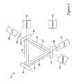
- FIG 2 is a perspective view of the illustrative multiple wavelength cavity ring down gas sensor 10 of Figure 1 .
- the optical cavity 12 is provided in a housing 40 defining optical segments 28, 30, and 32.
- the housing 40 may define a chamber 44 forming the optical cavity 12, while in other cases, it is contemplated that the housing 40 may include individual bores defining the individual segments 28, 30, and 32 of the optical cavity 12, if desired.
- the ends of optical segments 28, 30, and 32 may intersect mirrors 14, 16, and 18, which in the illustrative embodiment, are disposed about the side surfaces of the housing 40.
- mirror 18 may include an actuator 42 for actuating the position of mirror 18.
- mirror 18 may, in some cases, be an active mirror that may be mechanically and/or electrically deformable or otherwise actuatable so as to move the optical cavity in and out of resonance conditions for the electromagnetic radiation sources 20 and 22.
- the resonance condition for electromagnetic radiation source 22 may correspond to a wavelength for a high absorption line of the gas to be detected, while the resonance condition for electromagnetic radiation source 20 may correspond to a wavelength at which there is little or no absorption by the gas to be detected.
- the actuator 42 may be a piezoelectric actuator, but this is not required.
- piezoelectric actuator 42 may be configured to deform the mirror 18 when an electrical potential is applied across a piezoelectric actuator.
- an applied electrical potential may cause at least a portion of the mirror 18 to expand and/or contract.
- the center of the mirror 18 may move in and out in response to the applied electrical potential to the piezoelectric actuator, causing the position of the mirror 18 to change.
- the electrical potential may oscillate, causing the piezoelectric actuator to deform at a frequency of the applied oscillating electrical potential.
- the frequency that the mirror 18 oscillates may dictate a chopping frequency at which light pulses are periodically applied to the optical cavity 12, with cavity ring down decay times in between.
- the piezoelectric actuator may cause mirror 18 to deform around one or more node positions.
- the one or more node positions may be positions of the mirror 18 in which the optical cavity 12 may have a resonance condition.
- the mirror 18 may have a first node position corresponding to the resonance condition for electromagnetic radiation source 22, and a second node position corresponding to the resonance condition for electromagnetic radiation source 20.
- the oscillation of the mirror 18 may cause the optical cavity 12 to move in and out of the resonance conditions at the oscillating frequency of the piezoelectric actuator.
- actuator 42 may be any suitable actuator, as desired.
- FIG 3 is a schematic diagram of another illustrative multiple wavelength cavity ring down gas sensor 50.
- gas sensor 50 may be similar to gas sensor 10 shown in Figure 1 , except that light beams 26 and 27 enter the optical cavity 12 through a single entrance mirror, such as mirror 14, and, in some case cases, may include only a single detector, such as detector 24, for detecting the cavity ring down time decays of both light beams 26 and 27.
- a light coupling element 46 can be provided to direct both light beams 26 and 27 into the optical cavity 12.
- light beams 26 and 27 may be directed into the optical cavity 12 sequentially, alternatively, or at non-simultaneous times, if desired. This may be controlled by a control block 25.
- light beam 26 originating from laser 22 may pass through an AO modulator 36, light coupling element 46, and then the optical cavity 12 via mirror 14.
- Light beam 27 originating from laser 20 may, at a different time, pass through AO modulator 38 8 and be reflected or otherwise directed off of light coupling element 46 and enter optical cavity 12 via mirror 14.
- light coupling element 46 may be a beam splitter, a fiber optic switching network, or any other suitable optical coupler that can direct the laser beams 26 and 27 into the optical cavity 12, as desired.
- mirror 14 may be a passive mirror.
- mirrors 16 and/or 18 may be active mirrors.
- active mirrors 16 and/or 18 may be deformable or otherwise actuatable so as to move the optical cavity 12 in and out of the resonance conditions corresponding to the wavelengths of the electromagnetic radiation sources 20 and 22.
- mirror 14 may be the only entrance mirror, but this is not required.
- Detector 24 may be configured to detect the cavity ring down time decay of both light beams 26 and 27 in the optical cavity 12.
- the detector 24 may be an optical detector that is configured to detect optical light that leaks out one of the mirrors, such as mirror 14. However, it is contemplated that separate detectors may be provided for light beams 26 and 27, if desired.
- light beams 26 and 27 may be sequentially, alternatively, or otherwise coupled into optical cavity 12 at different times, as desired.
- the optical cavity 12 is in a resonance condition for light beam 26, such as according to the current state of the active mirror 16 or 18, the light beam 26 is amplified and interacts with the gas sample in the optical cavity 12.
- AO modulator 36 may shut off laser 22 when the intensity of the cavity reaches a desired level.
- Detector 24 may then detect a cavity ring down time decay of light beam 26 that is related to the absorption of the light beam 26 by the gas sample.
- AO modulator 38 may shut off laser 20 when the intensity of the cavity reaches a desired level.
- Detector 24 then may detect a cavity ring down time decay of light beam 27. As discussed above, the cavity ring down time decay of light beam 27 may be used as a baseline cavity ring down time decay of the optical cavity 12.
- the baseline cavity ring down time decay can be used with the cavity ring down time decay of beam 26 to more accurately determine the concentration of the gas of interest in the optical cavity 12 by, for example, helping to compensate for sensor variations such as sensor drift, which might be caused by, for example, sensor age, temperature or pressure changes, and/or other conditions.
- Control block 25 may be coupled to detector 24, and may use the baseline cavity ring down time decay to compensate a gas concentration value computed from the cavity ring down time decay of light beam 27.
- the cavity ring-down time of the optical cavity may be on the order of micro-seconds, such as, for example, 10 micro-seconds, depending on the concentration and/or degree of absorption by the gas.
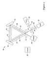
- FIG 4 is a perspective view of the illustrative multiple wavelength cavity ring down gas sensor 50 of Figure 3 .
- the optical cavity 12 is provided in housing 40 defining the optical segments 28, 30, and 32.
- the housing 40 may define a chamber 44, while in other cases, it is contemplated that the housing 40 may define individual optical segments 28, 30, and 32, if desired.
- the ends of optical segments 28, 30, and 32 may intersect mirrors 14, 16, and 18, which in the illustrative embodiment, are disposed about the side surfaces of the housing 40.
- mirror 18 may include actuator 42 for actuating the position of mirror 18, as further described above.
- optical cavity 12 is only illustrative, and that the optical cavity 12 can take on any form that permits incoming light beams 26 and 27 to be introduced into the cavity 12, travel around and be amplified by the cavity 12, and allow direct or indirect measurement of the cavity ring down time decays of light beams 26 and 27 in the optical cavity 12.
Abstract
Description
- The present disclosure relates generally to gas sensors, and more particularly, to cavity ring down gas sensors.
- Gas sensors are widely used across many diverse applications including commercial, industrial, military and other applications. The sensitivity of such gas sensors can vary, and the type of gas sensor used for a particular application is often selected depending on the required sensitivity and cost. In some applications, it may be desirable to detect gas concentrations as low as a few parts per billion, or even less. Many commercially available gas sensors do not have a high enough sensitivity or accuracy to detect these and other gas concentrations.
- The present disclosure relates generally to gas sensors, and more particularly, to cavity ring down gas sensors. In one illustrative embodiment, a gas sensor includes an optical cavity for receiving a gas to be detected, a first electromagnetic radiation source (e.g. laser), and a second electromagnetic radiation source (e.g. laser). The optical cavity is defined by one or more optical segments separating at least two mirrors. The first electromagnetic radiation source may be configured to emit a first beam of light having a first wavelength, wherein the first wavelength corresponds to an absorption line of a gas of interest. The second electromagnetic radiation source may be configured to emit a second beam of light having a second wavelength, where the second wavelength does not correspond to an absorption line of the gas of interest. The at least two mirrors can be configured to reflect the first beam of light and the second beam of light through the one or more optical segments, and thus the gas of interest. In some cases, the first beam of light and the second beam of light may be provided to the optical cavity simultaneously, while in other cases, the first beam of light and the second beam of light may be provided to the optical cavity sequentially, as desired.
- A detector may be used to detect a first cavity ring down time decay of the first beam of light, which may be related to the absorption of the first beam of light by the gas of interest in the optical cavity, and thus may provide a measure that is related to the concentration of the gas of interest in the optical cavity. In some cases, the same detector may be used to detect a second cavity ring down time decay of the second beam of light in the optical cavity, which may correspond to a baseline cavity ring down time. In some cases, rather than using the same detector, a second detector may be used to detect a cavity ring down time decay of the second beam of light in the optical cavity. In either case, the baseline cavity ring down time may be used to help increase the accuracy of the sensor by, for example, helping to compensate for sensor variations such as sensor drift, which might be caused by, for example, sensor age, temperature or pressure changes, and/or other conditions.
- The preceding summary is provided to facilitate an understanding of some of the innovative features unique to the present disclosure and is not intended to be a full description. A full appreciation of the disclosure can be gained by taking the entire specification, claims, drawings, and abstract as a whole.
- The disclosure may be more completely understood in consideration of the following description of various illustrative embodiments of the disclosure in connection with the accompanying drawings, in which:
-
Figure 1 is a schematic diagram of an illustrative multiple wavelength cavity ring down gas sensor; -
Figure 2 is a perspective view of the illustrative multiple wavelength cavity ring down gas sensor ofFigure 1 ; -
Figure 3 is a schematic diagram of another illustrative multiple wavelength cavity ring down gas sensor; and -
Figure 4 is a perspective view of the illustrative multiple wavelength cavity ring down gas sensor ofFigure 3 . - The following description should be read with reference to the drawings wherein like reference numerals indicate like elements throughout the several views. The description and drawings show several examples of the claimed invention, and are not meant to be limiting in any way.
-
Figure 1 is a schematic diagram of an illustrative multiple wavelength cavity ring downgas sensor 10. The illustrative multiple wavelength cavity ring downgas sensor 10 may provide a sensitive gas sensor that can be used to detect relatively low concentrations of gas in an environment. In some cases, thegas sensor 10 may be capable of accurately detecting gas concentrations as low as a few parts per billion, a few parts per trillion, or even a few parts per quadrillion, as desired. - In the illustrative embodiment of
Figure 1 , multiple wavelength cavity ring downgas sensor 10 may include two or moreelectromagnetic radiation sources optical cavity 12 configured to receive a gas sample, and two ormore detectors electromagnetic radiation sources beams beams lasers lasers light beam 26 oflaser 22 may be tuned to a high (or other) absorption line, or wavelength close thereto, of a gas to be detected andlight beam 27 oflaser 20 may be tuned off of the high absorption line of the gas to be detected. In some cases, thelasers - Alternatively,
lasers laser 22 may be selected to have a wavelength that is close to or at a high (or other) absorption line of a gas species to be detected, andlaser 20 may be selected to have a wavelength that is off of the high absorption line of the gas species to be detected. In some cases, quantum cascade lasers may be suitable. Some example lasers include, for example, lasers available from New Focus™, such as the Velocity Product line, Telecom, or Daylight Solutions, such as a 4.5 micron laser model number TLS-21045, or a Chiller Model 1001 having a model number TLS-21045. These are only illustrative. When thelasers - In the illustrative embodiment of
Figure 1 , theoptical cavity 12 has three linearoptical segments optical cavity 12. In this illustrative embodiment, theoptical cavity 12 includes threemirrors light beams optical cavity 12. As illustrated,mirrors optical cavity 12. As shown,mirror 14 intersects opticallinear segment 28 and opticallinear segment 30,mirror 16 intersects opticallinear segment 30 and opticallinear segment 32, andmirror 18 intersects opticallinear segment 32 and opticallinear segment 28 ofoptical cavity 12. While three mirrors are shown in the illustrative embodiment ofFigure 1 , it is contemplated that more or less mirrors may be used, as desired. For example, it is contemplated that two mirrors that causes light beams to travel back and forth between the two mirrors can be used, or more than three mirrors may be used, as desired. - In the illustrative embodiment of
Figure 1 ,mirrors mirror 18 may be an active mirror. In some cases,active mirror 18 may be deformable or otherwise actuatable, andpassive mirrors passive mirrors dielectric mirrors dielectric mirror optical cavity 12 to reduce loss. The at least partial transparency on the external surface of, for example,mirror 14, may helpincident light beam 26 pass throughmirror 14 to enter theoptical cavity 12. - In some cases,
active mirror 18 may be mechanically and/or electrically deformable or otherwise actuatable so as to move theoptical cavity 12 in and out of resonance conditions for theelectromagnetic radiation sources electromagnetic radiation source 22 may correspond to a wavelength for a high absorption line of the gas to be detected, while the resonance condition forelectromagnetic radiation source 20 may correspond to a wavelength at which there is little or no absorption by the gas to be detected. In some cases, theactive mirror 18 may be apiezoelectric mirror 18, but this is not required. When so provided,piezoelectric mirror 18 may be configured to deform when an electrical potential is applied across a piezoelectric element of themirror 18. For example, an applied electrical potential may cause at least a portion of the mirror to expand and/or contract. In one example, the center of thepiezoelectric mirror 18 may move in and out in response to the applied electrical potential, causing the position of themirror 18 to change. In some embodiments, the electrical potential may oscillate, causing thepiezoelectric mirror 18 to deform at a frequency of the applied oscillating electrical potential. The frequency that theactive mirror 18 oscillates may dictate a chopping frequency at which light pulses are periodically applied to theoptical cavity 12, with cavity ring down decay times in between. - In some cases, the
piezoelectric mirror 18 may be configured to deform around one or more node positions. The one or more node positions may be positions of thepiezoelectric mirror 18 in which theoptical cavity 12 may have a resonance condition. For example, in one case, the piezoelectric mirror may have a first node position corresponding to the resonance condition forelectromagnetic radiation source 22 and a second node position corresponding to the resonance condition forelectromagnetic radiation source 20. When so provided, the oscillation of thepiezoelectric mirror 18 may cause theoptical cavity 12 to move in and out of the resonance conditions at the oscillating frequency of thepiezoelectric mirror 18. In some cases, the resonance condition may occur twice for each oscillation cycle of themirror 18, but could be more or less depending on the resonance conditions of theoptical cavity 12. In one example, the oscillating frequency of thepiezoelectric mirror 18 may be such that the resonance conditions of theoptical cavity 12 occurs on the order of milliseconds, however, any suitable time period may be used. Similar tomirrors piezoelectric mirror 18 may be configured to have a relatively high reflectivity on the internal surface to reduce loss, and in some cases, be at least partially transparent on the external surface, when desired. - In the illustrative embodiment shown in
Figure 1 ,passive mirrors optical cavity 12, or more specifically,passive mirror 14 is the mirror in which thebeam 26 passes through to enter theoptical cavity 12, andpassive mirror 16 is the mirror in which thebeam 27 passes through to enter theoptical cavity 12. It is contemplated, however, that bothbeam optical cavity 12 is in a resonance condition, thebeam optical cavity 12 viapassive mirror optical cavity 12 and as new light is added by the correspondingelectromagnetic radiation sources optical cavity 12. In some cases, the amplification of thebeams electromagnetic radiation sources active mirror 18 causes theoptical cavity 12 to fall out of resonance, the light beam traveling around theoptical cavity 12 is stored for a period of time, typically on the order of microseconds, but decays with a cavity ring down time decay. The cavity ring down time decay will be dependent on the absorption of the light beams 26 or 27 by the gas that is present in theoptical cavity 12, if any. In some cases, theactive mirror 18 may cause theoptical cavity 12 to fall out of resonance for one of the electromagnetic radiation sources (such as light source 20) and fall into resonance for the other one of the electromagnetic radiation sources (such as light source 22), and visa-versa. - Rather than (or in addition to) having an
active mirror 18 that causes theoptical cavity 12 to fall out of/into resonance to selectively control the initiation of a cavity ring down time decay time, in some embodiments, an acousto-optic (AO) modulator, such asAO modulators electromagnetic radiations sources light optical cavity 12 and, in some cases, shut off the light that is input into theoptical cavity 12 when theoptical cavity 12 reaches a desired intensity. In some cases, theAO modulators e.g. detectors 24, 34) that receives light leaking out of theoptical cavity 12 through one of the mirrors. Rather than using AO modulators, it is contemplated that theelectromagnetic radiations sources -
Detectors light beams optical cavity 12. In some cases, thedetectors mirrors detectors optical cavity 12. - In operation, the
optical cavity 12 may couple inlight beam 26 viamirror 14 andlight beam 27 viamirror 16 at different times. In some cases, light beams 26 and 27 may be sequentially, alternatively, or otherwise coupled intooptical cavity 12 at different times, as desired. This may be controlled by acontrol block 23. When theoptical cavity 12 is in a resonance condition forlight beam 26, e.g. according to the current state of theactive mirror 18, thelight beam 26 may be amplified and may interact with the gas sample in theoptical cavity 12. In some cases,AO modulator 36 may shut offlaser 22 when the intensity of the cavity reaches a desired level, as detected byDetector 24.Detector 24 may then detect a cavity ring down time decay oflight beam 26, which is related to the absorption of thelight beam 26 by the gas sample in theoptical cavity 12. - When the
optical cavity 12 is in a resonance condition forlight beam 27, e.g. according to the current state of theactive mirror 18, thelight beam 27 is amplified, but sincelight beam 27 may not be at a high (or any other) absorption line of the gas to be detected, thelight beam 27 may not significantly interact with the gas sample in theoptical cavity 12. In some cases,AO modulator 38 may shut offlaser 20 when the intensity of the cavity reaches a desired level, as detected bydetector 34.Detector 34 may then detect a cavity ring down time decay oflight beam 27, which may be used as a baseline cavity ring down time decay for theoptical cavity 12. The baseline cavity ring down time decay can be used with the cavity ring down time decay ofbeam 26 to more accurately determine the concentration of the gas of interest in theoptical cavity 12 by, for example, helping to compensate for sensor variations such as sensor drift, which might be caused by, for example, sensor age, temperature or pressure changes, and/or other conditions.Control block 23 may be coupled todetectors light beam 27. In some cases, the cavity ring-down time of the optical cavity may be on the order of micro-seconds, such as, for example, 10 micro-seconds, depending on the concentration and/or degree of absorption by the gas. -
Figure 2 is a perspective view of the illustrative multiple wavelength cavity ring downgas sensor 10 ofFigure 1 . As illustrated, theoptical cavity 12 is provided in ahousing 40 definingoptical segments housing 40 may define achamber 44 forming theoptical cavity 12, while in other cases, it is contemplated that thehousing 40 may include individual bores defining theindividual segments optical cavity 12, if desired. The ends ofoptical segments mirrors housing 40. - As shown, and in some illustrative embodiments,
mirror 18 may include anactuator 42 for actuating the position ofmirror 18. As noted above with respect toFigure 1 ,mirror 18 may, in some cases, be an active mirror that may be mechanically and/or electrically deformable or otherwise actuatable so as to move the optical cavity in and out of resonance conditions for theelectromagnetic radiation sources electromagnetic radiation source 22 may correspond to a wavelength for a high absorption line of the gas to be detected, while the resonance condition forelectromagnetic radiation source 20 may correspond to a wavelength at which there is little or no absorption by the gas to be detected. In some cases, theactuator 42 may be a piezoelectric actuator, but this is not required. When so provided,piezoelectric actuator 42 may be configured to deform themirror 18 when an electrical potential is applied across a piezoelectric actuator. For example, an applied electrical potential may cause at least a portion of themirror 18 to expand and/or contract. In one example, the center of themirror 18 may move in and out in response to the applied electrical potential to the piezoelectric actuator, causing the position of themirror 18 to change. In some embodiments, the electrical potential may oscillate, causing the piezoelectric actuator to deform at a frequency of the applied oscillating electrical potential. The frequency that themirror 18 oscillates may dictate a chopping frequency at which light pulses are periodically applied to theoptical cavity 12, with cavity ring down decay times in between. - In some cases, the piezoelectric actuator may cause
mirror 18 to deform around one or more node positions. The one or more node positions may be positions of themirror 18 in which theoptical cavity 12 may have a resonance condition. For example, in one case, themirror 18 may have a first node position corresponding to the resonance condition forelectromagnetic radiation source 22, and a second node position corresponding to the resonance condition forelectromagnetic radiation source 20. When so provided, the oscillation of themirror 18 may cause theoptical cavity 12 to move in and out of the resonance conditions at the oscillating frequency of the piezoelectric actuator. While a piezoelectric actuator is used as an example, it is contemplated thatactuator 42 may be any suitable actuator, as desired. -
Figure 3 is a schematic diagram of another illustrative multiple wavelength cavity ring downgas sensor 50. In the illustrative embodiment,gas sensor 50 may be similar togas sensor 10 shown inFigure 1 , except that light beams 26 and 27 enter theoptical cavity 12 through a single entrance mirror, such asmirror 14, and, in some case cases, may include only a single detector, such asdetector 24, for detecting the cavity ring down time decays of bothlight beams - As shown in
Figure 3 , alight coupling element 46 can be provided to direct bothlight beams optical cavity 12. In some cases, light beams 26 and 27 may be directed into theoptical cavity 12 sequentially, alternatively, or at non-simultaneous times, if desired. This may be controlled by acontrol block 25. For example,light beam 26 originating fromlaser 22 may pass through anAO modulator 36,light coupling element 46, and then theoptical cavity 12 viamirror 14.Light beam 27 originating fromlaser 20 may, at a different time, pass throughAO modulator 38 8 and be reflected or otherwise directed off oflight coupling element 46 and enteroptical cavity 12 viamirror 14. It is contemplated thatlight coupling element 46 may be a beam splitter, a fiber optic switching network, or any other suitable optical coupler that can direct thelaser beams optical cavity 12, as desired. - In the illustrative embodiment of
Figure 3 ,mirror 14 may be a passive mirror. In some cases, mirrors 16 and/or 18 may be active mirrors. In some cases,active mirrors 16 and/or 18 may be deformable or otherwise actuatable so as to move theoptical cavity 12 in and out of the resonance conditions corresponding to the wavelengths of theelectromagnetic radiation sources mirror 14 may be the only entrance mirror, but this is not required. -
Detector 24 may be configured to detect the cavity ring down time decay of bothlight beams optical cavity 12. In some cases, thedetector 24 may be an optical detector that is configured to detect optical light that leaks out one of the mirrors, such asmirror 14. However, it is contemplated that separate detectors may be provided forlight beams - In operation, light beams 26 and 27 may be sequentially, alternatively, or otherwise coupled into
optical cavity 12 at different times, as desired. When theoptical cavity 12 is in a resonance condition forlight beam 26, such as according to the current state of theactive mirror light beam 26 is amplified and interacts with the gas sample in theoptical cavity 12. In some cases,AO modulator 36 may shut offlaser 22 when the intensity of the cavity reaches a desired level.Detector 24 may then detect a cavity ring down time decay oflight beam 26 that is related to the absorption of thelight beam 26 by the gas sample. - When the
optical cavity 12 is in a resonance condition forlight beam 27, such as according to the current state of theactive mirror light beam 27 is amplified, but since it is not at the high (or other) absorption line of the gas to be detected, it does not significantly interact with the gas sample in theoptical cavity 12. In some cases,AO modulator 38 may shut offlaser 20 when the intensity of the cavity reaches a desired level.Detector 24 then may detect a cavity ring down time decay oflight beam 27. As discussed above, the cavity ring down time decay oflight beam 27 may be used as a baseline cavity ring down time decay of theoptical cavity 12. The baseline cavity ring down time decay can be used with the cavity ring down time decay ofbeam 26 to more accurately determine the concentration of the gas of interest in theoptical cavity 12 by, for example, helping to compensate for sensor variations such as sensor drift, which might be caused by, for example, sensor age, temperature or pressure changes, and/or other conditions.Control block 25 may be coupled todetector 24, and may use the baseline cavity ring down time decay to compensate a gas concentration value computed from the cavity ring down time decay oflight beam 27. In some cases, the cavity ring-down time of the optical cavity may be on the order of micro-seconds, such as, for example, 10 micro-seconds, depending on the concentration and/or degree of absorption by the gas. -
Figure 4 is a perspective view of the illustrative multiple wavelength cavity ring downgas sensor 50 ofFigure 3 . As illustrated, theoptical cavity 12 is provided inhousing 40 defining theoptical segments housing 40 may define achamber 44, while in other cases, it is contemplated that thehousing 40 may define individualoptical segments optical segments mirrors housing 40. As shown, and in some cases,mirror 18 may includeactuator 42 for actuating the position ofmirror 18, as further described above. - It should be understood that the above-described
optical cavity 12 is only illustrative, and that theoptical cavity 12 can take on any form that permits incoming light beams 26 and 27 to be introduced into thecavity 12, travel around and be amplified by thecavity 12, and allow direct or indirect measurement of the cavity ring down time decays oflight beams optical cavity 12. - Having thus described some illustrative embodiments of the present disclosure, those of skill in the art will readily appreciate that yet other embodiments may be made and used within the scope of the claims hereto attached. It will be understood that this disclosure is, in many respect, only illustrative. Changes may be made in details, particularly in matters of shape, size, and arrangement of parts without exceeding the scope of the disclosure. The invention's scope is, of course, defined in the language in which the appended claims are expressed.
Claims (10)
- A gas sensor (10) for detecting a gas of interest, the gas of interest having one or more absorption lines, the gas sensor (10) comprising:an optical cavity (12) for receiving the gas of interest, the optical cavity (12) defined by one or more optical segments (28, 30, 32) separating at least two mirrors (14, 16, 18);a first electromagnetic radiation source (20) configured to emit a first beam of light having a first wavelength, wherein the first wavelength corresponds to one of the one or more absorption lines of the gas of interest;a second electromagnetic radiation source (22) configured to emit a second beam of light having a second wavelength, wherein the second wavelength does not correspond to any of the one or more absorption lines of the gas of interest;wherein the at least two mirrors (14, 16, 18) are configured to reflect the first beam of light and the second beam of light through the one or more optical segments (28, 30, 32) of the optical cavity (12) and the gas of interest; anda first detector (24) configured to detect a cavity ring down time decay of the first beam of light corresponding to an absorption of the first beam of light by the gas in the optical cavity (12).
- The gas sensor (10) of claim 1, wherein the first detector (24) is also configured to detect a cavity ring down time decay of the second beam of light in the optical cavity (12), indicating a baseline cavity ring down time.
- The gas sensor (10) of claim 1, further comprising a second detector (34) configured to detect a cavity ring down time decay of the second beam of light in the optical cavity (12), indicating a baseline cavity ring down time.
- The gas sensor (10) of claim 1, wherein at least one of the at least two mirrors (14, 16, 18) is actuatable to move the optical cavity (12) in and out of one or more node positions that provide one or more resonance conditions in the optical cavity (12).
- The gas sensor (10) of claim 1 further comprising an optical element that directs both the first beam of light and the second beam of light into the optical cavity (12).
- The gas sensor (10) of claim 1 wherein a first mirror (14) of the at least two mirrors (14, 16, 18) is an entrance mirror configured to couple both at least a portion of the first beam of light from the first electromagnetic radiation source (20) and at least a portion of the second beam of light from the second electromagnetic radiation source (22) into the optical cavity (12).
- The gas sensor (10) of claim 1 wherein a first mirror (14) of the at least two mirrors (14, 16, 18) is a first entrance mirror configured to couple at least a portion of the first beam of light from the first electromagnetic radiation source (20) into the optical cavity (12), and a second mirror (16) of the at least two mirrors (14, 16, 18) is a second entrance mirror configured to couple at least a portion of the second beam of light from the second electromagnetic radiation source (22) into the optical cavity (12).
- The gas sensor (10) of claim 1 wherein the first beam of light and the second beam of light are sequentially coupled into the optical cavity (12).
- A method of detecting a gas, the method comprising:providing an optical cavity (12) including at least two mirrors (14, 16, 18) separated by one or more optical segments (28, 30, 32), wherein the optical cavity (12) is configured to receive a gas;coupling a first light beam having a first wavelength from a first electromagnetic radiation source (20) into the optical cavity (12), wherein the first wavelength corresponds to an absorption wavelength of the gas in the optical cavity (12);detecting a first cavity ring down time decay of the first beam of light in the optical cavity (12);coupling a second light beam having a second wavelength from a second electromagnetic radiation source (22) into the optical cavity (12), wherein the second wavelength corresponds to a wavelength that has relatively little or no absorption by the gas in the optical cavity (12); anddetecting a second cavity ring down time decay of the second beam of light in the optical cavity (12), indicating a baseline cavity (12) ring down time.
- The method of claim 9 wherein the first beam of light and the second beam of light are sequentially coupled into the optical cavity (12).
Applications Claiming Priority (1)
| Application Number | Priority Date | Filing Date | Title |
|---|---|---|---|
| US12/825,985 US8437000B2 (en) | 2010-06-29 | 2010-06-29 | Multiple wavelength cavity ring down gas sensor |
Publications (2)
| Publication Number | Publication Date |
|---|---|
| EP2402736A2 true EP2402736A2 (en) | 2012-01-04 |
| EP2402736A3 EP2402736A3 (en) | 2015-01-21 |
Family
ID=44681512
Family Applications (1)
| Application Number | Title | Priority Date | Filing Date |
|---|---|---|---|
| EP11171105.7A Ceased EP2402736A3 (en) | 2010-06-29 | 2011-06-22 | Multiple wavelength cavity ring down gas sensor |
Country Status (2)
| Country | Link |
|---|---|
| US (1) | US8437000B2 (en) |
| EP (1) | EP2402736A3 (en) |
Families Citing this family (19)
| Publication number | Priority date | Publication date | Assignee | Title |
|---|---|---|---|---|
| CA2768946C (en) * | 2011-02-22 | 2019-01-08 | Queen's University At Kingston | Multiple wavelength cavity ring-down spectroscopy |
| US8785857B2 (en) * | 2011-09-23 | 2014-07-22 | Msa Technology, Llc | Infrared sensor with multiple sources for gas measurement |
| US9267844B2 (en) | 2012-05-23 | 2016-02-23 | Honeywell International Inc. | Method and apparatus for correcting bias error in ring-down spectroscopy |
| US8526000B1 (en) * | 2012-05-29 | 2013-09-03 | Honeywell International Inc. | Atomic sensor physics package with integrated transmissive and reflective portions along light paths |
| US9759610B2 (en) * | 2012-08-01 | 2017-09-12 | General Electric Company | Method and device for dissolved gas analysis |
| CN103487402B (en) * | 2013-10-14 | 2015-09-02 | 北京信息科技大学 | With the ring cavity internal chamber optical fiber laser gas detecting system of saturated absorption optical fiber |
| KR20160120336A (en) * | 2014-07-29 | 2016-10-17 | 토쿠시마 대학 | Inline concentration measurement device |
| FR3042866A1 (en) * | 2015-10-21 | 2017-04-28 | Aerovia | DEVICE FOR DETECTING GAS WITH VERY HIGH SENSITIVITY BASED ON A RESONATOR OF HELMHOLTZ |
| EP3427025B1 (en) | 2016-03-10 | 2022-05-04 | Li-Cor, Inc. | Multiple laser optical feedback assisted cavity enhanced absorption spectoscopy systems and methods |
| US10666012B2 (en) | 2017-03-13 | 2020-05-26 | Picomole Inc. | Apparatus and method of optimizing laser system |
| US10527492B2 (en) * | 2017-05-16 | 2020-01-07 | Li-Cor, Inc. | Mode matching method for absorption spectroscopy systems |
| CN108827913A (en) * | 2018-07-12 | 2018-11-16 | 河南师范大学 | A kind of multiple spot humidity sensor network based on fiber optic loop cavity-type BPM |
| US11035789B2 (en) | 2019-04-03 | 2021-06-15 | Picomole Inc. | Cavity ring-down spectroscopy system and method of modulating a light beam therein |
| JP7056627B2 (en) * | 2019-05-17 | 2022-04-19 | 横河電機株式会社 | Spectroscopic analyzer and spectroscopic analysis method |
| EP3985455A1 (en) * | 2020-10-16 | 2022-04-20 | The Swatch Group Research and Development Ltd | Device for measuring the degree of relative humidity inside a watch case |
| CN112903628B (en) * | 2021-01-25 | 2024-05-07 | 内蒙古光能科技有限公司 | Trace gas detection method under negative pressure state |
| CN113176220B (en) * | 2021-05-13 | 2023-06-16 | 北京环境特性研究所 | Gas detector and detection method thereof |
| CN113125368B (en) * | 2021-05-13 | 2023-06-16 | 北京环境特性研究所 | Aerosol extinction instrument and measuring method thereof |
| CN116448718B (en) * | 2023-04-19 | 2023-12-05 | 河北子曰机械设备有限公司 | Cavity ring-down tuning unit and cavity ring-down spectroscopy device |
Family Cites Families (154)
| Publication number | Priority date | Publication date | Assignee | Title |
|---|---|---|---|---|
| US4233568A (en) | 1975-02-24 | 1980-11-11 | Xerox Corporation | Laser tube mirror assembly |
| US4051372A (en) | 1975-12-22 | 1977-09-27 | Aine Harry E | Infrared optoacoustic gas analyzer having an improved gas inlet system |
| US4612647A (en) | 1982-12-27 | 1986-09-16 | Litton Systems, Inc. | High performance laser and method of making same |
| DE3311808C2 (en) | 1983-03-31 | 1985-09-26 | Fraunhofer-Gesellschaft zur Förderung der angewandten Forschung e.V., 8000 München | Semiconductor laser array with a Fabry-Perot interferometer |
| US5311280A (en) | 1983-07-21 | 1994-05-10 | Kearfott Guidance & Navigation Corporation | Laser light length control assembly for ring laser gyro |
| US4614961A (en) | 1984-10-09 | 1986-09-30 | Honeywell Inc. | Tunable cut-off UV detector based on the aluminum gallium nitride material system |
| FR2581190B1 (en) | 1985-04-25 | 1987-06-19 | Elf France | INTERFEROMETRIC GAS DETECTOR |
| US4672624A (en) | 1985-08-09 | 1987-06-09 | Honeywell Inc. | Cathode-block construction for long life lasers |
| US5450053A (en) | 1985-09-30 | 1995-09-12 | Honeywell Inc. | Use of vanadium oxide in microbolometer sensors |
| US4795258A (en) | 1987-04-06 | 1989-01-03 | Litton Systems, Inc. | Nonplanar three-axis ring laser gyro with shared mirror faces |
| US4870224A (en) | 1988-07-01 | 1989-09-26 | Intel Corporation | Integrated circuit package for surface mount technology |
| FR2639711B1 (en) | 1988-11-25 | 1992-12-31 | Elf Aquitaine | METHOD FOR THE SIMULTANEOUS DETECTION OF SEVERAL GASES IN A GAS MIXTURE, AND APPARATUS FOR CARRYING OUT SAID METHOD |
| US4973131A (en) | 1989-02-03 | 1990-11-27 | Mcdonnell Douglas Corporation | Modulator mirror |
| US5022745A (en) | 1989-09-07 | 1991-06-11 | Massachusetts Institute Of Technology | Electrostatically deformable single crystal dielectrically coated mirror |
| US5135304A (en) | 1990-05-11 | 1992-08-04 | Boc Health Care, Inc. | Gas analysis system having buffer gas inputs to protect associated optical elements |
| US5146465A (en) | 1991-02-01 | 1992-09-08 | Apa Optics, Inc. | Aluminum gallium nitride laser |
| US6147756A (en) | 1992-01-22 | 2000-11-14 | Northeastern University | Microspectrometer with sacrificial layer integrated with integrated circuit on the same substrate |
| US5909280A (en) | 1992-01-22 | 1999-06-01 | Maxam, Inc. | Method of monolithically fabricating a microspectrometer with integrated detector |
| US5278435A (en) | 1992-06-08 | 1994-01-11 | Apa Optics, Inc. | High responsivity ultraviolet gallium nitride detector |
| US5408319A (en) | 1992-09-01 | 1995-04-18 | International Business Machines Corporation | Optical wavelength demultiplexing filter for passing a selected one of a plurality of optical wavelengths |
| JPH0766331A (en) | 1993-08-02 | 1995-03-10 | Motorola Inc | Manufacture of semiconductor device package |
| US5418868A (en) | 1993-11-17 | 1995-05-23 | At&T Corp. | Thermally activated optical switch |
| DE4402054A1 (en) | 1994-01-25 | 1995-07-27 | Zeiss Carl Fa | Gas laser emitting at two wavelengths |
| US5500761A (en) | 1994-01-27 | 1996-03-19 | At&T Corp. | Micromechanical modulator |
| US5512750A (en) | 1994-06-03 | 1996-04-30 | Martin Marietta Corporation | A-dual band IR sensor having two monolithically integrated staring detector arrays for simultaneous, coincident image readout |
| US5528040A (en) | 1994-11-07 | 1996-06-18 | Trustees Of Princeton University | Ring-down cavity spectroscopy cell using continuous wave excitation for trace species detection |
| US5550373A (en) | 1994-12-30 | 1996-08-27 | Honeywell Inc. | Fabry-Perot micro filter-detector |
| US5679965A (en) | 1995-03-29 | 1997-10-21 | North Carolina State University | Integrated heterostructures of Group III-V nitride semiconductor materials including epitaxial ohmic contact, non-nitride buffer layer and methods of fabricating same |
| US5739554A (en) | 1995-05-08 | 1998-04-14 | Cree Research, Inc. | Double heterojunction light emitting diode with gallium nitride active layer |
| US5723706A (en) | 1995-06-23 | 1998-03-03 | Uop | Process for the treatment of halogenated organic feedstocks |
| US5677538A (en) | 1995-07-07 | 1997-10-14 | Trustees Of Boston University | Photodetectors using III-V nitrides |
| US5900650A (en) | 1995-08-31 | 1999-05-04 | Kabushiki Kaisha Toshiba | Semiconductor device and method of manufacturing the same |
| US6324192B1 (en) | 1995-09-29 | 2001-11-27 | Coretek, Inc. | Electrically tunable fabry-perot structure utilizing a deformable multi-layer mirror and method of making the same |
| US5629951A (en) | 1995-10-13 | 1997-05-13 | Chang-Hasnain; Constance J. | Electrostatically-controlled cantilever apparatus for continuous tuning of the resonance wavelength of a fabry-perot cavity |
| JP2723105B2 (en) | 1995-11-22 | 1998-03-09 | 株式会社ニッショー | Blood collection needle holder |
| US5763943A (en) | 1996-01-29 | 1998-06-09 | International Business Machines Corporation | Electronic modules with integral sensor arrays |
| US5832017A (en) | 1996-03-15 | 1998-11-03 | Motorola Inc | Reliable near IR VCSEL |
| JPH09286039A (en) | 1996-04-22 | 1997-11-04 | Komatsu Ltd | Plate-shaped composite and its production |
| KR100468342B1 (en) | 1996-05-15 | 2005-06-02 | 텍사스 인스트루먼츠 인코포레이티드 | LDMOS device with self-aligned RESURF region and method of manufacturing the same |
| US5758968A (en) | 1996-07-15 | 1998-06-02 | Digimelt Inc. | Optically based method and apparatus for detecting a phase transition temperature of a material of interest |
| DE19635421C1 (en) | 1996-08-23 | 1997-12-11 | Deutsche Forsch Luft Raumfahrt | Resonance absorption spectrometer for ion spectral analysis |
| US5834331A (en) | 1996-10-17 | 1998-11-10 | Northwestern University | Method for making III-Nitride laser and detection device |
| US5892582A (en) | 1996-10-18 | 1999-04-06 | Micron Optics, Inc. | Fabry Perot/fiber Bragg grating multi-wavelength reference |
| EP0938660B1 (en) | 1996-11-18 | 2000-04-12 | Fraunhofer-Gesellschaft Zur Förderung Der Angewandten Forschung E.V. | Micromechanical transmission measuring cell |
| US6080988A (en) | 1996-12-20 | 2000-06-27 | Nikon Corporation | Optically readable radiation-displacement-conversion devices and methods, and image-rendering apparatus and methods employing same |
| US5933245A (en) | 1996-12-31 | 1999-08-03 | Honeywell Inc. | Photoacoustic device and process for multi-gas sensing |
| US5915051A (en) | 1997-01-21 | 1999-06-22 | Massascusetts Institute Of Technology | Wavelength-selective optical add/drop switch |
| US5815277A (en) | 1997-06-20 | 1998-09-29 | The Board Of Trustees Of The Leland Stanford Junior Univesity | Deflecting light into resonant cavities for spectroscopy |
| US5912740A (en) | 1997-06-20 | 1999-06-15 | The Board Of Trustees Of The Leland Stanford Junior University | Ring resonant cavities for spectroscopy |
| US6545739B1 (en) | 1997-09-19 | 2003-04-08 | Nippon Telegraph And Telephone Corporation | Tunable wavelength filter using nano-sized droplets of liquid crystal dispersed in a polymer |
| EP0905546A3 (en) | 1997-09-26 | 2002-06-19 | Nippon Telegraph and Telephone Corporation | Stacked thermo-optic switch, switch matrix and add-drop multiplexer having the stacked thermo-optic switch |
| US5960025A (en) | 1997-10-06 | 1999-09-28 | Honeywell Inc. | Device and method for achieving beam path alignment of an optical cavity |
| US6040895A (en) | 1997-10-08 | 2000-03-21 | Siemens Aktiengesellschaft | Method and device for controlled illumination of an object for improving identification of an object feature in an image of the object |
| US5835231A (en) | 1997-10-31 | 1998-11-10 | The United States Of America As Represented By The Secretary Of Commerce | Broad band intra-cavity total reflection chemical sensor |
| US5982788A (en) | 1997-11-05 | 1999-11-09 | California Institute Of Technology | Semi-monolithic cavity for external resonant frequency doubling and method of performing the same |
| US6438149B1 (en) | 1998-06-26 | 2002-08-20 | Coretek, Inc. | Microelectromechanically tunable, confocal, vertical cavity surface emitting laser and fabry-perot filter |
| US6084682A (en) | 1998-04-15 | 2000-07-04 | The Board Of Trustees Of The Leland Stanford Junior University | Cavity-locked ring down spectroscopy |
| US6091504A (en) | 1998-05-21 | 2000-07-18 | Square One Technology, Inc. | Method and apparatus for measuring gas concentration using a semiconductor laser |
| US6584126B2 (en) | 1998-06-26 | 2003-06-24 | Coretek, Inc. | Tunable Fabry-Perot filter and tunable vertical cavity surface emitting laser |
| US6597713B2 (en) | 1998-07-22 | 2003-07-22 | Canon Kabushiki Kaisha | Apparatus with an optical functional device having a special wiring electrode and method for fabricating the same |
| EP0995969A3 (en) | 1998-10-19 | 2000-10-18 | Canon Kabushiki Kaisha | Semiconductor device, semiconductor laser and gyro |
| US6380531B1 (en) | 1998-12-04 | 2002-04-30 | The Board Of Trustees Of The Leland Stanford Junior University | Wavelength tunable narrow linewidth resonant cavity light detectors |
| JP3538045B2 (en) | 1998-12-09 | 2004-06-14 | 三菱電機株式会社 | RF circuit module |
| US6233052B1 (en) | 1999-03-19 | 2001-05-15 | The Board Of Trustees Of The Leland Stanford Junior University | Analog detection for cavity lifetime spectroscopy |
| US6483130B1 (en) | 1999-03-24 | 2002-11-19 | Honeywell International Inc. | Back-illuminated heterojunction photodiode |
| US6185233B1 (en) | 1999-06-08 | 2001-02-06 | Alcatel | Output power controlled wavelength stabilizing system |
| US6516010B1 (en) | 1999-07-13 | 2003-02-04 | Agere Systems, Inc. | Method and apparatus for active numeric temperature compensation of an etalon in a wavelength stabilized laser |
| US6421127B1 (en) | 1999-07-19 | 2002-07-16 | American Air Liquide, Inc. | Method and system for preventing deposition on an optical component in a spectroscopic sensor |
| US6393894B1 (en) | 1999-07-27 | 2002-05-28 | Honeywell International Inc. | Gas sensor with phased heaters for increased sensitivity |
| US6287940B1 (en) | 1999-08-02 | 2001-09-11 | Honeywell International Inc. | Dual wafer attachment process |
| DE19948542A1 (en) | 1999-10-08 | 2001-05-23 | Zeiss Carl Jena Gmbh | Arrangement in which light is directed onto a surface from a light source |
| US6406578B1 (en) | 1999-10-19 | 2002-06-18 | Honeywell Inc. | Seal and method of making same for gas laser |
| US6295130B1 (en) | 1999-12-22 | 2001-09-25 | Xerox Corporation | Structure and method for a microelectromechanically tunable fabry-perot cavity spectrophotometer |
| US6535327B1 (en) | 2000-02-02 | 2003-03-18 | Picarro, Inc. | CGA optical parametric oscillator |
| US6377350B1 (en) | 2000-02-03 | 2002-04-23 | Informal Diagnostics, Inc | Frequency sequencing using CRDS |
| US6452680B1 (en) | 2000-02-03 | 2002-09-17 | Informed Diagnostics, Inc. | Cavity ring down arrangement for non-cavity filling samples |
| US6590710B2 (en) | 2000-02-18 | 2003-07-08 | Yokogawa Electric Corporation | Fabry-Perot filter, wavelength-selective infrared detector and infrared gas analyzer using the filter and detector |
| US6208798B1 (en) | 2000-03-03 | 2001-03-27 | E-Tek Dynamics | Variable optical attenuator with thermo-optic control |
| US6608711B2 (en) | 2000-03-03 | 2003-08-19 | Axsun Technologies, Inc. | Silicon on insulator optical membrane structure for fabry-perot MOEMS filter |
| US6879014B2 (en) | 2000-03-20 | 2005-04-12 | Aegis Semiconductor, Inc. | Semitransparent optical detector including a polycrystalline layer and method of making |
| US6670599B2 (en) | 2000-03-27 | 2003-12-30 | Aegis Semiconductor, Inc. | Semitransparent optical detector on a flexible substrate and method of making |
| EP1148037A1 (en) | 2000-04-19 | 2001-10-24 | Blösch Holding AG | Process for the production of an anti-reflective coating on watchcover glasses |
| US6310904B1 (en) | 2000-05-31 | 2001-10-30 | Honeywell International, Inc. | Measurement method to facilitate production of self-aligning laser gyroscope block |
| US6384953B1 (en) | 2000-06-29 | 2002-05-07 | The United States Of America As Represented By The Secretary Of The Navy | Micro-dynamic optical device |
| US7012696B2 (en) | 2000-07-12 | 2006-03-14 | Macquarie Research Ltd. | Optical heterodyne detection in optical cavity ringdown spectroscopy |
| US6424419B1 (en) | 2000-07-28 | 2002-07-23 | Northrop Grumman Corporation | System and method for providing cavity length control of a ring laser gyroscope |
| US6658034B2 (en) | 2000-12-13 | 2003-12-02 | Picarro, Inc. | Surface-emitting semiconductor laser |
| US6492726B1 (en) | 2000-09-22 | 2002-12-10 | Chartered Semiconductor Manufacturing Ltd. | Chip scale packaging with multi-layer flip chip arrangement and ball grid array interconnection |
| US6670559B2 (en) | 2000-12-13 | 2003-12-30 | International Business Machines Corp. | Electromagnetic shield for printed circuit boards |
| US6583917B2 (en) | 2000-12-22 | 2003-06-24 | Pirelli Cavi E Sistemi S.P.A. | Optical intensity modulation device and method |
| US6836501B2 (en) | 2000-12-29 | 2004-12-28 | Finisar Corporation | Resonant reflector for increased wavelength and polarization control |
| US6627983B2 (en) | 2001-01-24 | 2003-09-30 | Hsiu Wen Tu | Stacked package structure of image sensor |
| SG95637A1 (en) | 2001-03-15 | 2003-04-23 | Micron Technology Inc | Semiconductor/printed circuit board assembly, and computer system |
| US6404648B1 (en) | 2001-03-30 | 2002-06-11 | Hewlett-Packard Co. | Assembly and method for constructing a multi-die integrated circuit |
| US20020191268A1 (en) | 2001-05-17 | 2002-12-19 | Optical Coating Laboratory, Inc, A Delaware Corporation | Variable multi-cavity optical device |
| US7049004B2 (en) | 2001-06-18 | 2006-05-23 | Aegis Semiconductor, Inc. | Index tunable thin film interference coatings |
| US6594059B2 (en) | 2001-07-16 | 2003-07-15 | Axsun Technologies, Inc. | Tilt mirror fabry-perot filter system, fabrication process therefor, and method of operation thereof |
| CN100354699C (en) | 2001-08-02 | 2007-12-12 | 伊吉斯半导体公司 | Tunable optical instruments |
| US6816636B2 (en) | 2001-09-12 | 2004-11-09 | Honeywell International Inc. | Tunable optical filter |
| US7145165B2 (en) | 2001-09-12 | 2006-12-05 | Honeywell International Inc. | Tunable laser fluid sensor |
| US20070133001A1 (en) | 2001-09-12 | 2007-06-14 | Honeywell International Inc. | Laser sensor having a block ring activity |
| US7015457B2 (en) | 2002-03-18 | 2006-03-21 | Honeywell International Inc. | Spectrally tunable detector |
| KR20040077666A (en) | 2001-11-28 | 2004-09-06 | 이지스 세미컨덕터 | Package for electro-optical components |
| US7046362B2 (en) | 2001-12-12 | 2006-05-16 | Trustees Of Princeton University | Fiber-optic based cavity ring-down spectroscopy apparatus |
| US6959024B2 (en) | 2002-02-28 | 2005-10-25 | Picarro, Inc. | Laser Tuning by spectrally dependent spatial filtering |
| US6728286B2 (en) | 2002-08-07 | 2004-04-27 | Honeywell International Inc. | Method of joining mirrors to ring laser gyro block assemblies |
| US6982999B1 (en) | 2003-01-21 | 2006-01-03 | Picarro,Inc. | Multipass second harmonic generation |
| US6967976B2 (en) | 2002-08-29 | 2005-11-22 | Picarro, Inc. | Laser with reflective etalon tuning element |
| US6959023B1 (en) | 2002-08-29 | 2005-10-25 | Picarro, Inc. | Laser with reflective etalon tuning element |
| US6865198B2 (en) | 2002-09-27 | 2005-03-08 | Battelle Memorial Institute | Cavity ringdown spectroscopy system and method |
| US6741381B1 (en) | 2002-11-08 | 2004-05-25 | Picarro, Inc. | Modified tunable acousto-optic filter |
| US6859284B2 (en) | 2002-12-02 | 2005-02-22 | Picarro, Inc. | Apparatus and method for determining wavelength from coarse and fine measurements |
| US6792010B2 (en) | 2002-12-20 | 2004-09-14 | Picarro, Inc. | Laser with reduced parasitic etalon effects |
| US7147695B2 (en) | 2002-12-13 | 2006-12-12 | New Jersey Institute Of Technology | Microfabricated microconcentrator for sensors and gas chromatography |
| US7035298B2 (en) | 2003-01-21 | 2006-04-25 | Picarro, Inc. | Frequency conversion efficiency |
| GB0302174D0 (en) | 2003-01-30 | 2003-03-05 | Shaw Andrew M | Sensing apparatus and methods |
| US20040234198A1 (en) | 2003-03-21 | 2004-11-25 | Aegis Semiconductor, Inc. | Tunable and switchable multiple-cavity thin film optical filters |
| US7064836B2 (en) | 2003-04-21 | 2006-06-20 | The Board Of Trustees Of The Leland Stanford Junior University | Brewster's angle flow cell for cavity ring-down spectroscopy |
| US20040255853A1 (en) | 2003-05-15 | 2004-12-23 | Aegis Semiconductor | PECVD reactor in-situ monitoring system |
| JP2007524828A (en) | 2003-06-20 | 2007-08-30 | アイギス セミコンダクター インコーポレイテッド | Thermo-optic filter and infrared sensor using the same |
| US7050170B2 (en) | 2003-07-22 | 2006-05-23 | Picarro, Inc. | Apparatus and method for maintaining uniform and stable temperature for cavity enhanced optical spectroscopy |
| US20050082480A1 (en) | 2003-08-26 | 2005-04-21 | Aegis Semiconductor, Inc. | Infrared camera system |
| US7221827B2 (en) | 2003-09-08 | 2007-05-22 | Aegis Semiconductor, Inc. | Tunable dispersion compensator |
| WO2005036239A2 (en) | 2003-10-07 | 2005-04-21 | Aegis Semiconductor, Inc. | Tunable filter membrane structures and methods of making |
| WO2005036240A1 (en) | 2003-10-07 | 2005-04-21 | Aegis Semiconductor, Inc. | Tunable optical filter with heater on a cte-matched transparent substrate |
| US7116423B2 (en) | 2003-10-31 | 2006-10-03 | Picarro, Inc. | Flow cell for optical detection having reduced sensitivity to refractive index variation |
| US7089781B2 (en) | 2003-11-04 | 2006-08-15 | Honeywell International, Inc. | Detector with condenser |
| FR2862409B1 (en) | 2003-11-17 | 2006-04-14 | Datacard Inc | ADAPTER ELEMENT FOR PROGRAMMABLE ELECTRONIC SUPPORTS |
| US7113286B2 (en) | 2003-12-03 | 2006-09-26 | Tiger Optics, Llc | Apparatus and method for improved analysis of liquids by continuous wave-cavity ring down spectroscopy |
| US7154595B2 (en) | 2003-12-17 | 2006-12-26 | Picarro, Inc. | Cavity enhanced optical detector |
| US7352464B2 (en) | 2004-01-05 | 2008-04-01 | Southwest Sciences Incorporated | Oxygen sensor for aircraft fuel inerting systems |
| US7113256B2 (en) | 2004-02-18 | 2006-09-26 | Asml Netherlands B.V. | Lithographic apparatus and device manufacturing method with feed-forward focus control |
| US7106763B2 (en) | 2004-03-18 | 2006-09-12 | Picarro, Inc. | Wavelength control for cavity ringdown spectrometer |
| US20050254056A1 (en) | 2004-05-13 | 2005-11-17 | Alexander Kachanov | System and method for controlling the light source of a cavity ringdown spectrometer |
| US20080204879A1 (en) | 2004-06-25 | 2008-08-28 | Omar Manzardo | Miniature Lamellar Grating Interferometer Based on Silicon Technology |
| US7586114B2 (en) | 2004-09-28 | 2009-09-08 | Honeywell International Inc. | Optical cavity system having an orthogonal input |
| US7902534B2 (en) | 2004-09-28 | 2011-03-08 | Honeywell International Inc. | Cavity ring down system having a common input/output port |
| US7265842B2 (en) | 2004-10-14 | 2007-09-04 | Picarro, Inc. | Method for detecting a gaseous analyte present as a minor constituent in an admixture |
| US7263871B2 (en) | 2004-12-08 | 2007-09-04 | Finesse Solutions Llc. | System and method for gas analysis using doubly resonant photoacoustic spectroscopy |
| US7259856B2 (en) | 2005-02-16 | 2007-08-21 | Picarro, Inc. | Method for the precise measurement of the wavelength of light |
| US20070146720A1 (en) | 2005-12-23 | 2007-06-28 | Honeywell International Inc. | Spectrometer method and apparatus for near infrared to terahertz wavelengths |
| US7777886B2 (en) | 2006-02-23 | 2010-08-17 | Picarro, Inc. | Optical system including a weak lens and a beam translation plate for selectively coupling to the lowest order mode of an optical resonator |
| US7535573B2 (en) | 2006-02-23 | 2009-05-19 | Picarro, Inc. | Cavity enhanced optical spectroscopy with a cavity having a predetermined deviation from a mode degeneracy condition |
| US7420686B2 (en) | 2006-02-23 | 2008-09-02 | Picarro, Inc. | Wavelength measurement method based on combination of two signals in quadrature |
| US7369242B2 (en) | 2006-03-17 | 2008-05-06 | Honeywell International Inc. | Cavity ring-down spectrometer for semiconductor processing |
| US7656532B2 (en) | 2006-04-18 | 2010-02-02 | Honeywell International Inc. | Cavity ring-down spectrometer having mirror isolation |
| US7649189B2 (en) | 2006-12-04 | 2010-01-19 | Honeywell International Inc. | CRDS mirror for normal incidence fiber optic coupling |
| US7813886B2 (en) | 2006-12-07 | 2010-10-12 | Picarro, Inc. | Calibration of frequency monitors having dual etalon signals in quadrature |
| US7612885B2 (en) * | 2006-12-22 | 2009-11-03 | Honeywell International Inc | Spectroscopy method and apparatus for detecting low concentration gases |
| US7810376B2 (en) | 2007-11-06 | 2010-10-12 | Picarro, Inc. | Mitigation of gas memory effects in gas analysis |
| US20090323055A1 (en) | 2008-06-25 | 2009-12-31 | Honeywell International Inc. | Crds brewster gas cell |
| US7663756B2 (en) | 2008-07-21 | 2010-02-16 | Honeywell International Inc | Cavity enhanced photo acoustic gas sensor |
| US7808640B2 (en) | 2008-07-30 | 2010-10-05 | Honeywell International Inc. | Photoacoustic spectroscopy system |
| US7884938B2 (en) * | 2009-01-29 | 2011-02-08 | Honeywell International Inc. | Multiple beam wide band CRDS cavity sensor and detector |
-
2010
- 2010-06-29 US US12/825,985 patent/US8437000B2/en not_active Expired - Fee Related
-
2011
- 2011-06-22 EP EP11171105.7A patent/EP2402736A3/en not_active Ceased
Non-Patent Citations (1)
| Title |
|---|
| None |
Also Published As
| Publication number | Publication date |
|---|---|
| US20110317164A1 (en) | 2011-12-29 |
| EP2402736A3 (en) | 2015-01-21 |
| US8437000B2 (en) | 2013-05-07 |
Similar Documents
| Publication | Publication Date | Title |
|---|---|---|
| US8437000B2 (en) | Multiple wavelength cavity ring down gas sensor | |
| US7663756B2 (en) | Cavity enhanced photo acoustic gas sensor | |
| US10739254B2 (en) | Optical absorption spectroscopy based gas analyzer systems and methods | |
| US20040202399A1 (en) | System and method for measuring physical, chemical and biological stimuli using vertical cavity surface emitting lasers with integrated tuner | |
| US20040061859A1 (en) | Cavity ringdown spectroscopy system and method | |
| US7884938B2 (en) | Multiple beam wide band CRDS cavity sensor and detector | |
| US10422740B2 (en) | Dual wavelength source gas detector | |
| JP2010539464A (en) | Spectral polarization hyperspectral imaging device | |
| EP2434274A1 (en) | Sensor, method for detecting the presence and / or concentration of an analyte using the sensor and use of the method | |
| WO2004093272A3 (en) | System and method for measuring physical, chemical and biological stimuli using vertical cavity surface emitting lasers with integrated tuner | |
| EP2654143A1 (en) | Frequency tunable laser system | |
| US8269972B2 (en) | Beam intensity detection in a cavity ring down sensor | |
| CN109580541A (en) | A kind of optical heterodyne cavity ring-down spectroscopy measuring device and method | |
| NO20151276A1 (en) | Noise canceling detector | |
| JP2005321244A (en) | Optical measuring instrument | |
| CN103884683A (en) | Optical sensor based on cascade connection of F-P (Fabry-Parot) semiconductor laser device and thin film F-P optical filter | |
| US9244002B1 (en) | Optical method and system for measuring an environmental parameter | |
| US11976963B2 (en) | Fibre-optic acoustic sensor and associated measurement system, vehicle and measurement method | |
| EP3201605B1 (en) | Laser beam stop elements and spectroscopy systems including the same | |
| WO2009064517A1 (en) | Micro-lidar velocity, temperature, density, concentration sensor | |
| US9945740B2 (en) | Two wavelength optical interferometric pressure switch and pressure transducers | |
| JPH08201278A (en) | Spectrum measuring device | |
| KR101861321B1 (en) | Monitoring system for emergency situation using dual pulse light | |
| CN111684335A (en) | Spectrometer, imaging device, scanning device, and position measurement device | |
| WO2017164033A1 (en) | Gas measuring device |
Legal Events
| Date | Code | Title | Description |
|---|---|---|---|
| 17P | Request for examination filed |
Effective date: 20110622 |
|
| AK | Designated contracting states |
Kind code of ref document: A2 Designated state(s): AL AT BE BG CH CY CZ DE DK EE ES FI FR GB GR HR HU IE IS IT LI LT LU LV MC MK MT NL NO PL PT RO RS SE SI SK SM TR |
|
| AX | Request for extension of the european patent |
Extension state: BA ME |
|
| PUAI | Public reference made under article 153(3) epc to a published international application that has entered the european phase |
Free format text: ORIGINAL CODE: 0009012 |
|
| PUAL | Search report despatched |
Free format text: ORIGINAL CODE: 0009013 |
|
| AK | Designated contracting states |
Kind code of ref document: A3 Designated state(s): AL AT BE BG CH CY CZ DE DK EE ES FI FR GB GR HR HU IE IS IT LI LT LU LV MC MK MT NL NO PL PT RO RS SE SI SK SM TR |
|
| AX | Request for extension of the european patent |
Extension state: BA ME |
|
| RIC1 | Information provided on ipc code assigned before grant |
Ipc: G01N 21/31 20060101ALI20141212BHEP Ipc: G01N 21/03 20060101AFI20141212BHEP Ipc: G01N 21/39 20060101ALI20141212BHEP |
|
| 17Q | First examination report despatched |
Effective date: 20150216 |
|
| RAP1 | Party data changed (applicant data changed or rights of an application transferred) |
Owner name: HONEYWELL INTERNATIONAL INC. |
|
| STAA | Information on the status of an ep patent application or granted ep patent |
Free format text: STATUS: THE APPLICATION HAS BEEN REFUSED |
|
| 18R | Application refused |
Effective date: 20180702 |