EP2396768B1 - Quality evaluation of sequences of images - Google Patents
Quality evaluation of sequences of images Download PDFInfo
- Publication number
- EP2396768B1 EP2396768B1 EP10713808.3A EP10713808A EP2396768B1 EP 2396768 B1 EP2396768 B1 EP 2396768B1 EP 10713808 A EP10713808 A EP 10713808A EP 2396768 B1 EP2396768 B1 EP 2396768B1
- Authority
- EP
- European Patent Office
- Prior art keywords
- image
- images
- test image
- metric
- sequence
- Prior art date
- Legal status (The legal status is an assumption and is not a legal conclusion. Google has not performed a legal analysis and makes no representation as to the accuracy of the status listed.)
- Not-in-force
Links
Images


Classifications
-
- G—PHYSICS
- G06—COMPUTING; CALCULATING OR COUNTING
- G06T—IMAGE DATA PROCESSING OR GENERATION, IN GENERAL
- G06T7/00—Image analysis
- G06T7/0002—Inspection of images, e.g. flaw detection
-
- G—PHYSICS
- G06—COMPUTING; CALCULATING OR COUNTING
- G06T—IMAGE DATA PROCESSING OR GENERATION, IN GENERAL
- G06T7/00—Image analysis
- G06T7/97—Determining parameters from multiple pictures
-
- G—PHYSICS
- G06—COMPUTING; CALCULATING OR COUNTING
- G06T—IMAGE DATA PROCESSING OR GENERATION, IN GENERAL
- G06T2207/00—Indexing scheme for image analysis or image enhancement
- G06T2207/10—Image acquisition modality
- G06T2207/10016—Video; Image sequence
-
- G—PHYSICS
- G06—COMPUTING; CALCULATING OR COUNTING
- G06T—IMAGE DATA PROCESSING OR GENERATION, IN GENERAL
- G06T2207/00—Indexing scheme for image analysis or image enhancement
- G06T2207/30—Subject of image; Context of image processing
- G06T2207/30168—Image quality inspection
Definitions
- the present disclosure relates to image quality evaluation. More in particular, embodiments of the present invention relate to quality evaluation of sequences of images.
- Quality evaluation is useful for improving the user experience in many multimedia applications.
- Generating objective quality metrics that can accurately estimate the perceived quality of image sequences may promote quality evaluation.
- Quality evaluation may be used with some multimedia applications. Such applications include video compression, pre-processing, post-processing, and watermarking among others.
- video compression encoding techniques may use video quality metrics to improve encoding parameters through rate distortion optimization, and pre-processing techniques rely on video quality metrics to optimize pre-processing filter parameters given a target application or environment.
- video post-processing content is adapted to be displayed on a variety of display types at various spatial and temporal resolutions, and the resulting video quality may be evaluated for each display type.
- video quality metrics can be used to minimize the perceivable distortion due to the watermark when embedding a watermark, or could be considered when detecting and/or deciphering the embedded watermark signal.
- the distortion introduced to video through compression, pre/post processing, etc. can be both spatial and temporal in nature.
- cross view/stereo distortion may also be introduced.
- Spatial distortions include such compression artifacts as quantization, blocking, blurring, and ringing artifacts among others.
- Spatial distortion metrics have been extensively investigated in the image quality evaluation community but the effects of temporal and multi-view distortion are much less well known. Such distortions lead to temporal or/and view inconsistencies in the resulting video.
- Embodiments of the present invention relate to quality evaluation of sequences of images.
- a quality evaluation method for evaluation of a sequence of images comprising: performing disparity estimation among images in one or more domains to generate disparity vectors; and computing a metric based on the disparity vectors to evaluate the quality.
- a system for computing consistency of a test image sequence comprising: a disparity estimator, to estimate disparities among images of the test image sequence or disparities between images of the test image sequence and images of a reference image sequence through generation of disparity vectors; a metric calculator, to compute the consistency of the test image sequence as a function of the disparity vectors generated by the disparity estimator.
- novel systems and methods for computing the temporal and/or multi-view consistency of an image sequence are disclosed.
- disparity estimation methods are used, such as a block based motion estimation algorithm like the Enhanced Predictive Zonal Search (EPZS) (see references [12], [13], [14] incorporated herein by reference in their entirety) to track the movement of pixel regions within the image and computes the consistency of the sequence after disparity, e.g. motion and illumination change, compensation.
- EZS Enhanced Predictive Zonal Search
- Stereo view disparity can consider similar methods for analysis.
- Temporal e.g. motion
- disparity compensated pixel information also including deblocking, for example
- the techniques and embodiments discussed in the present disclosure also apply to images in a bitstream mode.
- Any existing disparity estimation technique such as any block based motion estimation algorithm, with or without illumination compensation support, can be used for this purpose, and the accuracy of the metric will depend on the accuracy of the disparity estimation method used.
- Overlapped block motion estimation can also be used in order to avoid spurious results on block edges.
- example embodiments of metrics are described that can take into account different aspects of temporal and/or multi-view quality.
- a first embodiment is a full reference metric that can measure the consistency of the disparity vectors computed during the disparity estimation process for the reference and test sequences.
- Other two embodiments are non reference metrics that can measure the consistency of pixel values across successive disparity compensated images of the test sequence.
- the present disclosure describes a set of temporal and stereo/multi-view consistency metrics to help measure the extent of temporal and/or multi-view distortion artifacts in video sequences.
- the metrics according to the present disclosure perform disparity, e.g. motion, estimation in the input sequences, and measure the temporal consistency in the disparity compensated images of the sequence.
- the consistency in "cross-view" compensated images can be evaluated.
- global and local weighting parameters can be used to ensure that only the perceivable distortions will be measured by the metrics.
- a perceptual weighting scheme is also included to take into account global events such as scene transitions, such as cuts, fades, and cross-fades, in the sequence, as well as local properties, such as texture, object and image edges among others.
- temporal/multi-view features can be further combined with existing or new spatial distortion metrics for better characterization of the overall distortion of the video sequence.
- two image sequences, a reference sequence, and test sequence are taken as inputs.
- the terms “2D” and “3D” respectively refer to the phrases “two dimensional” and “three dimensional.”
- the sequences can undergo an initial registration step which ensures that the test sequence is properly aligned (temporally, 2D spatially, and for stereo images, 3D spatially) with the reference sequence.
- This step could also include other operations such as resolution/aspect ratio conversion, gamma correction, etc., that adapt the inputs to particular display conditions.
- registration can be performed by registering the test image sequence with the reference image sequence or, alternatively, by registering the reference image sequence with the test image sequence. Moreover, both types of registration can also be performed and their results combined.
- the sequences can then be low-pass filtered to reduce noise, and then for each image of each sequence, disparity estimation (e.g., motion estimation and/or illumination parameter estimation) is performed to find the prediction images from past and future neighboring images. Similar analysis can be performed across views in stereo image pairs. Temporal or/and stereo view consistency metrics can then be calculated using the disparity vectors and/or prediction images as input. Finally, the different consistency metrics can be combined together using different weighting parameters to generate a combined disparity metric that accounts for temporal and/or stereo view consistencies. This combined metric can then be further combined with other metrics such as other temporal, stereo view, frequency, or spatial metrics finally providing a combined spatio-temporal-stereo view distortion metric.
- disparity estimation e.g., motion estimation and/or illumination parameter estimation
- Similar analysis can be performed across views in stereo image pairs.
- Temporal or/and stereo view consistency metrics can then be calculated using the disparity vectors and/or prediction images as input.
- the different consistency metrics can be combined together using different weighting
- n denotes the image index in the sequence.
- the sequences 102 and 104 can comprise stereo video pairs if evaluation of the quality of stereo video is desired.
- a full-reference quality metric like metric 118 of FIG. 1 provides an estimate of the distortion of the test sequence 104 relative to the reference sequence 102 while non-reference metrics like metrics 120 of FIG. 1 provide a "blind" estimate of the distortion of the test sequence 104.
- the test sequence 104 is registered 106 with the reference sequence 102, and both sequences 102, 104 are spatially filtered 108, 110.
- spatial filtering 108, 110 can comprise a low-pass filter that reduces noise in the images and helps to improve the accuracy of disparity estimation.
- Disparity estimation of the reference sequence and test sequence is then performed in blocks 112, 114.
- disparity estimation 112, 114 can include, for example, motion estimation and/or illumination change estimation or, more generally, disparity estimation among images in one or more domains D1 . . . Dm.
- Registration 106 can be performed by registering the test image sequence with the reference image sequence or, alternatively, by registering the reference image sequence with the test image sequence. Moreover, both types of registration can also be performed and their results combined.
- Disparity estimated metrics 116 based on the operations performed in 112, 114 are then computed.
- metrics 116 can include, for example, a full reference metric 118 or one or more non reference metrics 120.
- metrics 118 and 120 can be combined 122.
- one or more spatial metrics (or, more generally, metrics in one or more additional domains also inclusive, if desired, of a frequency domain) can also be computed 124 (e.g., with methods known in the art) and then combined with the combined metrics 122.
- output metrics D SDE at the output of the system shown in FIG. 1 can include one or more of temporal, spatial, and/or multi-view quality metrics.
- FIG. 1 can be used, for example, in several processes or systems, such as a video compression process or system 128, a video pre-processing process or system 130, a video post-processing process or system 132, or a video watermarking process or system 134.
- a video compression process or system 128, a video pre-processing process or system 130, a video post-processing process or system 132, or a video watermarking process or system 134 can be used, for example, in several processes or systems, such as a video compression process or system 128, a video pre-processing process or system 130, a video post-processing process or system 132, or a video watermarking process or system 134.
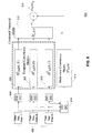
- FIG. 2 provides an embodiment of the disparity estimation blocks 112 and 114 of FIG. 1 , where an additional compensation process can also be taken into account, if desired.
- disparity can be estimated with reference to one or more domains, such as time (motion) or brightness (illumination change).
- motion estimation In the case of the disparity estimation involving a motion estimation (ME) process, temporally adjacent neighboring images, both past and future, of each input image of the test sequence or reference sequence can be considered, and the motion vectors that provide the best match to the input image be correspondingly estimated. Typically, the matches are found on a fixed or adaptive block basis (e.g., 8x8 blocks of pixels) but other sizes as well as shape based methods can also be used for this purpose.
- Motion estimation methods per se are known to the person skilled in the art and will not be described here in detail. Any kind of motion estimation could be used with the teaching of the present disclosure, also including, for example, overlapped and non-overlapped block motion estimation, affine motion estimation, parabolic and parametric among others.
- a possible disparity estimation method is the Enhanced Predictive Zonal Search (EPZS) and its Multidimensional Extensions (e.g. N-D EPZS).
- EZS Enhanced Predictive Zonal Search
- N-D EPZS Multidimensional Extensions
- Other methods such as methods based on optical flow, can also be considered.
- a motion compensation process forms a reconstructed image, where the reconstructed image is a prediction of the input image given the corresponding neighbor.
- Motion compensation processes per se are known to the person skilled in the art and will not be described here in detail. Similar characteristics can be considered for disparity estimation across multiple views.
- N past and N future spatially filtered neighbors of a filtered input image f n can be used, by way of example, in the disparity estimation process described above.
- the person skilled in the art will understand that alternative embodiments are also possible, where only past neighbors, only future neighbors, or a number of past neighbors different from the number of future neighbors can be used.
- the notations f ⁇ n-N ,...,f ⁇ n-1 ,...,f ⁇ n+N of FIG. 2 indicate reconstructed images corresponding to each neighbor, f n + 1 , such that the pixel value at each location, s , in f ⁇ n+i corresponds to the value at pixel location s-dv n+i (s) in f n + i , where s is a vector containing the horizontal and vertical co-ordinates of the pixel, and dv n+i (s) is the disparity vector estimated by the disparity estimation process. More in particular, as shown in FIG.
- disparity estimation is calculated in blocks 202( ⁇ i) and disparity compensation based on the disparity vectors 206( ⁇ i) at the output of blocks 202( ⁇ i) is calculated in blocks 204( ⁇ i).
- Each disparity estimation block 202( ⁇ i) receives as inputs the input image f n and the past or future neighbor image f n +i .
- the neighbor images can be stored in a first buffer 208.
- each disparity compensation block 204( ⁇ i) receives as inputs the disparity vector 206( ⁇ i) and the past or future neighbor image f n + i .
- the neighbor images can be stored in the first buffer 208 or in a second buffer 210, as shown in FIG. 2 .
- the second buffer 210 can also store the combined outputs of the disparity compensation blocks 204( ⁇ i) (see combiner 212), in order to allow future disparity compensations to also depend on the result of previous disparity compensations.
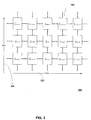
- FIG. 3 shows an adaptation of the embodiment of FIG. 2 to a multi-view case, where a plurality of estimation (or estimation and compensation) blocks 300 is illustrated.
- the same terminology of FIG. 2 can be applied to the multi-view case shown in FIG. 3 by assuming that one view is at position m, and the other views are at positions m ⁇ j where j represents a spatial or viewing angle distance from the first view.
- block 306 of FIG. 3 represents processing of the input sequence of view m+1 at time n+1.
- the disparity estimation process provides as output the set of reconstructed images and the corresponding disparity vectors used to create the reconstructed images.
- the quality metrics use the outputs of the disparity estimation process to determine the temporal or view feature consistency of the input sequences. Three different embodiments of consistency metrics will be discussed in the following paragraphs. Throughout the present disclosure, they will be called as follows:
- the disparity vector consistency metric is a full reference metric making use of both the reference and test sequences, while the other metrics are non-reference metrics.
- the results from the metrics can be combined into a final metric, and/or be combined with one or more other metrics of different type, similarly to what shown by reference numerals 122 and 126 in FIG. 1 .
- the metric is a temporal metric
- this can be combined with several other spatial quality metrics to determine the final objective quality of the sequence.
- the metric is a multi-view metric
- the metric could be combined with a temporal metric, possibly generated using the same principles, and other spatial metrics, resulting in a joint spatio-temporal-stereo view quality metric.
- a metric in a first domain can be combined with one or more additional metrics in other domains.
- the disparity vector consistency metric is a full reference metric. It relies on the assumption that if the disparity estimation is performed accurately on both the reference sequence and the test sequence (see, for example, sequences 102 and 104 of FIG. 1 ), the disparity vectors (see, for example, vectors 206 of FIG. 2 ) calculated for each pixel, block, or region in the reference and test sequences should be similar unless the test sequence contains temporal or view distortions.
- disparity vector similarity can also depend on a number of other factors such as the temporal distance (or viewing angle or spatial distance in the case of multi-view images) between the image and its neighbor for which disparity vectors are extracted, the occurrence of scene changes/transitions and other discontinuities in the underlying video content including illumination changes, occlusions caused by object and image edges, etc.
- the disparity vector consistency metric for each image at time, or view, n, of the test sequence given the corresponding image at time or view, n , of the reference sequence can be obtained as, D DV f n t
- the consistency function h ⁇ dv n + i t s , dv n + i r s between a test image disparity vector and a reference image disparity vector returns a value in the range [0, 1] such that a higher value represents lower feature consistency.
- the consistency function can be an indicator function that returns 0, if the two disparity vectors are deemed similar, and 1, if the two disparity vectors are different.
- the test of whether two disparity vectors are similar can be performed using a phase and magnitude difference threshold between the two disparity vectors such that if either is exceeded, then the disparity vectors are deemed different.
- Another possibility is to let the consistency function h ( ⁇ ) depend on the magnitude of the difference vector. For example, h ( ⁇ ) could be ⁇ dv n + i t s , dv n + i r s ⁇ MAX_DV , where MAX_DV is the maximum possible disparity vector magnitude.
- Equation (1) also depends on parameters w n + i and c n + i ( s ).
- the parameter w n + i is a "global" weighting parameter, meaning that there is one such parameter per image at a temporal location or view.
- the global parameter w n + i depends on the temporal distance, i , as well as on whether the underlying content is detected to contain an event, such as a scene change, which will affect the accuracy of the disparity estimation.
- the global parameter w n + i could also depend on the viewing angle or distance between the views, if that is known.
- w n + i is set to decrease as i increases in absolute value. If a scene change is detected between the current image and the neighboring image, then the global parameter w n + i is set to 0, and the weights given to the remaining images are adjusted accordingly.
- the parameter c n+i ( s ) is a "local" weighting parameter dependent on the spatial neighborhood of the reference image, meaning that there is one such parameter for each pixel s of an image or, more generally, for a region or set of regions of an image.
- the value of the local parameter c n + i ( s ) lies in the range [0, 1] and it represents the probability that the disparity vectors in the reference and test sequences will be consistent given the consistency of neighboring disparity vectors in the reference sequence.
- One possibility for calculating the value of the local parameter c n + i ( s ) is to define a function dependent on the number of disparity vectors in the neighborhood of s in the test sequence that are similar to the disparity vector at s in the reference sequence.
- the similarity of disparity vectors can be computed in the same manner as in the computation of the consistency function h ( ⁇ ) (e.g., using thresholds for differences in disparity vector phase and magnitude).
- the neighborhood of s for example, can be limited to the 4-connected neighborhood of the associated pixel block. Larger neighborhoods may also be considered with appropriate weightings to take into account the distance from s.
- Disparity vectors estimated near object and image boundaries generally tend to be less correlated with their spatial neighbors, and also less correlated between the test and reference sequences. Therefore, using such disparity vectors can adversely affect the accuracy of the distortion metric.
- the local weighting parameter attempts to resolve this issue by lowering the weights assigned to potentially spurious disparity vector differences.
- the above metric D DV can be calculated in the temporal domain, the multi-view domain, or in a combined temporal and multi-view domain.
- FIG. 4 shows an embodiment of a method or system 400 where the metric D DV is calculated in a combined temporal and multi-view domain.
- the metric can be calculated separately for each view to obtain a set of metrics, D DV T n m where n represents time, and m represents the view for which the temporal metric is calculated. See, in particular, blocks 402 and 406, which represent the test sequence and reference sequence inputs, respectively, for each view. Disparity estimation is calculated for each test sequence 406 and for each reference sequence 408. For each view at time n , the outputs of the disparity estimation blocks for the test sequence and reference sequence (see, e.g., the disparity vectors 206 of previously discussed FIG.
- the metric D DV can be calculated at each time n , to obtain a metric, D DV S n , that measures the disparity vector consistency between the views.
- disparity estimation is performed among the various views of the test sequence (see block 418 of FIG. 4 ) and among the various views of the reference sequence (see block 420 of FIG. 4 ).
- the outputs of the disparity estimation blocks 418 and 420 for the test sequence and the reference sequence in the multi-view domain are then used to calculate the D DV function of Equation (1) in the multi-view domain, D DV S n , as shown by block 422 in FIG. 4 .
- the temporal metrics over all the views can be combined at block 416 to obtain a value D ⁇ DV T n using, for example, the average of the values at each m .
- the variance, minimum value or maximum, value may also be used depending on the application and how the human visual system reacts to differences in temporal quality across views.
- the function F DV ST ⁇ can, for example, be a weighted combination, as indicated by reference numeral 424 in FIG. 4 , where the weights w 1 , and w 2 can be determined empirically based on subjective data.
- the above metric can also be defined for a specific region, or set of regions (also possibly including regions subsampled at different resolutions and/or regions selected as a result of an image partitioning process, such as image segmentation analysis), within an image, instead of the entire image.
- the metric may also be pooled over time (multiple images in the sequence) to determine statistics such as the average, minimum, maximum consistency within a sequence of images or pooled over a set of regions within the image.
- the specific region or set of regions can be user-selectable or can be detected and/or selected using an automatic region of interest detection scheme, such as, for example, a k-means segmentation method, watersheds, algorithms based on the Hausdorff distance, or algorithms targeting applications such as face detection (e.g., Gabor Feature Extraction, Viola-Jones face detector, etc).
- an automatic region of interest detection scheme such as, for example, a k-means segmentation method, watersheds, algorithms based on the Hausdorff distance, or algorithms targeting applications such as face detection (e.g., Gabor Feature Extraction, Viola-Jones face detector, etc).
- face detection e.g., Gabor Feature Extraction, Viola-Jones face detector, etc.
- FIG. 4 makes reference to a combined temporal / multi-view embodiment, the person skilled in the art will understand that, more generally, disparity estimations in a first domain and a second domain (or even more than two domains) can be used
- a second embodiment of a metric in accordance with the present disclosure comprises the disparity estimated feature difference metric, which is a non reference metric.
- the disparity estimated feature difference metric which is a non reference metric.
- this metric will also use the results of the disparity compensation blocks 204 of previously discussed FIG. 2 .
- the metric attempts to measure the temporal or multi-view consistency between images of a given sequence by comparing the image f n to predictions f ⁇ n-N ,...,f ⁇ n-1 ,...,f ⁇ n+N of the image obtained by disparity estimation from previous and future images in the sequence for temporal distortion, or multiple images of a scene for multi-view distortion.
- disparity estimation has already been discussed above with reference to FIG. 2 and FIG. 3 .
- the factors mentioned in the disparity vector consistency metric can affect the calculation of the feature difference metric.
- FIG. 5 shows an example of how the D FD function of Equation (3) can be obtained.
- Reference numeral 502 represents the input image f n .
- Reference numerals 504(-N), ..., 504(-1), 504(+1), ..., 504(+N), etc. represent the various reconstructed images f ⁇ n-N ,...,f ⁇ n-1 ,...,f ⁇ n+N obtained at the end of the estimation process previously discussed FIG. 2 .
- Blocks 506(-N), ..., 506(-1), 506(+1), ..., 506(+N), etc. represent the calculation of the expression inside the square brackets of Equation (3), where local weighting parameters c n+i ( s ) are taken into consideration. Once this is done, the output 508 is generated through a sum where also the global weighting parameters w n + i are taken into account.
- the region of interest may be the entire image, or a sub-image.
- a sub-image could be of arbitrary shape and/or size, or could be of a predefined shape or size, e.g. blocks of size 32x32.
- Sub-images could also be non-overlapping or overlapping and could span multiple images.
- a further extension of the metric can be to compute the D FD metric over multiple image regions and spatially pool the values.
- the spatial pooling can include using the maximum distortion among all the regions or an average of the values above an x% percentile (e.g., average of distortion values above 90% percentile), which takes into account the tendency for subjective quality to be heavily biased by regions with high distortion or an average distortion over all the regions of interest.
- the values can also he pooled temporary to obtain a combined metric over time. Distortion could also he weighted according to foreground/background, object analysis, texture etc.
- w n+i represents a global weighting parameter and c n+i represents a local weighting parameter.
- the function d ⁇ f ⁇ n + i l x y , f n l x y represents a pixel difference measure between the pixel ( x,y ) in image n , and the corresponding predicted pixel from image n + i .
- this can be the absolute difference of pixel values, in which case D FD will represent a weighted sum absolute difference (SAD), or the square of the difference of pixel values, in which case D FD will represent a weighted sum squared error (SSE).
- SAD weighted sum absolute difference
- SSE weighted sum squared error
- the global weighting parameter should take into account the temporal or multi-view distance between frames, as well as the possibility of global events such as scene changes in the sequence.
- both temporal and spatial view consistency may be important in determining the perceived quality of the output video. Therefore, the above metric can be extended to include both the temporal and the multi-view domain, as shown in the embodiment of method or system 600 of FIG. 6 , which is conceptually similar to the embodiment of FIG. 4 . Differently from such embodiment, disparity correction (DC) will also be performed, as indicated by the wording DE/DC on blocks 604 and 614.
- DC disparity correction
- D FD can be calculated temporally for each view (see blocks 606, 608 and 610), and then combined (see block 612) as an average, variance, maximum, or minimum of the values over all views.
- This will give a combined temporal distortion metric at a particular frame at time n, D ⁇ FD T n .
- the disparity estimated feature difference metric discussed above with reference to FIG. 5 and FIG. 6 calculates an average difference measure between pixel values in an image and its neighbors, it does not measure the variation in pixel values over time. Therefore, the present disclosure also proposes a disparity estimated feature variation metric to take into account temporal and muiti-view variations through inclusion of disparity compensated pixels. This metrics is also a non references metric.
- w n + i a global weight
- c n + i (x,y) a local spatial weight determined by the neighborhood of the pixel.
- H and V represent the number of horizontal and vertical pixels in the image region of interest.
- the metric can be calculated in multiple image regions and then combined to form a final image based metric using for example, the average, maximum, or average of the values above a threshold.
- the variation is computed at a pixel level
- another possibility is to compute the metric at multiple resolutions by successively downsampling the image prior to computing the metric.
- the multi-resolution technique can be implemented by averaging the pixel values over a block of pixels with varying block sizes and computing the variation at a block level. Overlapped blocks can also be used to smooth out spurious values at the block boundaries. Complexity in the calculation of Equations (5) and (6) can be reduced by subsampling the neighborhood of the pixel. In case of a combined spatial, temporal and multi-view metric, neighborhood is defined in the spatial, temporal and multi-view dimensions.
- FIG. 7 shows an example of how the D FV function of Equation (5) can be obtained.
- Reference numeral 702 represents a pixel value of the input image f n (x, y).
- Reference numerals 704(-N), ..., 704(-1), 704(+1), ..., 704(+N), etc. represent pixel values of the various reconstructed images f ⁇ n-N (x,y) ,...,f ⁇ n-1 (x,y) ,...,f ⁇ n+N (x,y) obtained at the end of the estimation process previously discussed FIG. 2 .
- Blocks 706(-N), ..., 706(-1), 706(+1), ..., 706(+N), etc. represent the calculation of the expression inside the square brackets of Equation (5), where local weighting parameters c n + i (s) are taken into consideration. Once this is done, the output 708 is generated through a sum where also the global weighting parameter w n + i are taken into account.
- D ⁇ FV T n can be the average of the temporal variation measurements obtained for each view.
- the combined temporal variation metric can be used to measure the differences among the temporal variation metrics calculated for each view.
- D ⁇ FV T n ⁇ m w m S V D FV T n m , D ⁇ FV T n ⁇ m w m S
- V( ⁇ ) represents a distance metric as in (5)
- D ⁇ FV T n ⁇ m w m S D FV T n m ⁇ m w m S
- w m S represents a weighting parameter applied to each view m .
- the individual temporal and multi-view, distortion metrics of the three embodiments discussed above can be combined to form various combined distortion metrics such that the effects of the individual distortions are weighted according to their perceptual significance, as also indicated by the combination symbol 122 discussed with reference to FIG. 1 .
- a combined temporal distortion metric which takes into account all of the above features can be computed as a weighted combination of each individual metric.
- a combined multi-view video distortion metric can be computed in a similar way.
- the value of D DE can represent any one of a distortion estimated multi-view consistency metric, temporal consistency metric, or a temporal and multi-view consistency metric.
- the metric values may be obtained on subsampled or reduced resolution images, or on specific regions of interest as mentioned in the previous sections. Temporal or view subsampling could also be considered.
- the spatial distortion metric D S can be any one or combination of the existing spatial quality metrics such as PSNR, MSE, SSIM (see reference [9]) etc., or a combination of spatial feature metrics.
- the above metrics can also be calculated over multiple image regions, instead of the entire image at once, or on subsampled images at various resolutions, etc.
- the combined metrics can then be pooled over the multiple image regions or resolutions, and then temporally over the entire sequence to obtain a combined quality metric for the sequence.
- the pooling can simply be that of averaging over the distortion values for each region.
- Another possibility is to compute the maximum distortion over all regions, and use a combination of the maximum and mean distortion.
- temporal pooling another possibility is to compute a maximum average distortion over a moving window.
- embodiments of the methods and systems according to the present disclosure can also be applied to still images, for example multi-view/stereo still representation.
Description
- The present disclosure relates to image quality evaluation. More in particular, embodiments of the present invention relate to quality evaluation of sequences of images.
- Quality evaluation is useful for improving the user experience in many multimedia applications. Generating objective quality metrics that can accurately estimate the perceived quality of image sequences may promote quality evaluation.
- Quality evaluation may be used with some multimedia applications. Such applications include video compression, pre-processing, post-processing, and watermarking among others. In video compression, encoding techniques may use video quality metrics to improve encoding parameters through rate distortion optimization, and pre-processing techniques rely on video quality metrics to optimize pre-processing filter parameters given a target application or environment. In video post-processing, content is adapted to be displayed on a variety of display types at various spatial and temporal resolutions, and the resulting video quality may be evaluated for each display type. In watermarking, video quality metrics can be used to minimize the perceivable distortion due to the watermark when embedding a watermark, or could be considered when detecting and/or deciphering the embedded watermark signal.
- One approach to quality measurement is to perform subjective tests. However, such tests may incur some difficulty and expense to setup. Developing objective image and quality metrics that can provide quality ratings to approach those obtained using subjective tests (see references [1], [2] incorporated herein by reference in their entirety). Currently, however, in spite of such difficulty or expense (see reference [3] incorporated herein by reference in its entirety), most in the video compression community continue to use MSE (Mean Squared Error) and PSNR (Peak Signal-to-Noise Ratio) as distortion metrics. Recently, the considerable interest in new applications, such as 3D/stereo video delivery, has renewed the interest in the creation of better and more accurate metrics that better model the human visual system.
- The distortion introduced to video through compression, pre/post processing, etc., can be both spatial and temporal in nature. In multi-view video, cross view/stereo distortion may also be introduced. Spatial distortions include such compression artifacts as quantization, blocking, blurring, and ringing artifacts among others. Spatial distortion metrics have been extensively investigated in the image quality evaluation community but the effects of temporal and multi-view distortion are much less well known. Such distortions lead to temporal or/and view inconsistencies in the resulting video.
- Early attempts at accounting for temporal distortion in objective perceptual quality metrics consider a temporal contrast sensitivity function to determine the perceivable differences in the temporal domain of the sequence (see references [4], [5], [6] incorporated herein by reference in their entirety). These methods, however, do not account for motion in the sequences, and as such, do not completely measure the perceived temporal consistency of the sequences. Similarly, for stereo images, stereo view disparity among views is not considered.
- Other objective quality metrics such as those shown in references [7], [8], incorporated herein by reference in their entirety, measure the temporal consistency of the sequence by measuring the pixel differences or correlation between successive images in the sequence. However, they do not perform motion estimation prior to the measurement, and again, may not adequately estimate the true temporal consistency of the sequence.
- In reference [11], incorporated herein by reference in its entirety, the well-known structural similarity image quality metric (see reference [9] incorporated herein by reference in its entirety), was extended to the video domain by introducing a global weighting scheme based on the amount of motion in each image of the sequence. However, the method ignores the relationship between temporal consistency and quality. A more sophisticated motion compensated structural similarity metric was proposed in reference [10], incorporated herein by reference in its entirety. However, the proposed technique relies on optical flow computation, which may be complex to implement and cannot be used in image regions containing significant motion.
- In "Objective Quality Metric based on Spatial-Temporal Distortion", 2008 International Conference on Multimedia and Information Technology, MMIT '08, IEEE, Piscataway, NJ, USA, 30 December 2008, pages 813-816, XP031477125, ISBN: 978-0-7695-3556-2, Chunting Yang et al. disclose video quality metrics capable of capturing spatial distortions in video sequences. In addition to temporal artifacts, the disclosed metrics can quantify the spatial distortions in video sequences and differentiate the type of distortions.
- The accompanying drawings, which are incorporated into and constitute a part of this specification, illustrate one or more embodiments of the present disclosure and, together with the detailed description and the examples, serve to explain the principles and implementations of the disclosure.
-
- FIGURE (
FIG.) 1 shows an embodiment of the quality evaluation systems and methods according to the present disclosure. -
FIG. 2 shows in more detail an embodiment of the disparity estimation block ofFIG. 1 . -
FIG. 3 shows an adaptation of the scheme ofFIG. 2 to a multi-view environment. -
FIG. 4 shows a first embodiment of metric in accordance with the present disclosure. -
FIG. 5 shows a second embodiment of metric in accordance with the present disclosure. -
FIG. 6 shows a combined temporal/multi-view example of the embodiment ofFIG. 5 . -
FIG. 7 shows a third embodiment of metric in accordance with the present disclosure. - Embodiments of the present invention relate to quality evaluation of sequences of images. A quality evaluation method for evaluation of a sequence of images is provided, comprising: performing disparity estimation among images in one or more domains to generate disparity vectors; and computing a metric based on the disparity vectors to evaluate the quality.
- In an embodiment, a system for computing consistency of a test image sequence is provided, comprising: a disparity estimator, to estimate disparities among images of the test image sequence or disparities between images of the test image sequence and images of a reference image sequence through generation of disparity vectors; a metric calculator, to compute the consistency of the test image sequence as a function of the disparity vectors generated by the disparity estimator.
- Further example features of example embodiments of the present disclosure are described in the specification, drawings, claims and abstract of the present application
- According to some embodiments of the present disclosure, novel systems and methods for computing the temporal and/or multi-view consistency of an image sequence are disclosed. Unlike existing schemes, disparity estimation methods are used, such as a block based motion estimation algorithm like the Enhanced Predictive Zonal Search (EPZS) (see references [12], [13], [14] incorporated herein by reference in their entirety) to track the movement of pixel regions within the image and computes the consistency of the sequence after disparity, e.g. motion and illumination change, compensation. Stereo view disparity can consider similar methods for analysis.
- In accordance with some of the embodiments of the present disclosure, Temporal (e.g. motion) or/and view disparity, and disparity compensated pixel information (also including deblocking, for example), are used to measure the consistency of temporal and multi-view features between images of a sequences, as well as the consistency of the features in a test sequence relative to a reference sequence. The techniques and embodiments discussed in the present disclosure also apply to images in a bitstream mode.
- Any existing disparity estimation technique, such as any block based motion estimation algorithm, with or without illumination compensation support, can be used for this purpose, and the accuracy of the metric will depend on the accuracy of the disparity estimation method used. Overlapped block motion estimation can also be used in order to avoid spurious results on block edges.
- In addition, example embodiments of metrics are described that can take into account different aspects of temporal and/or multi-view quality. A first embodiment is a full reference metric that can measure the consistency of the disparity vectors computed during the disparity estimation process for the reference and test sequences. Other two embodiments are non reference metrics that can measure the consistency of pixel values across successive disparity compensated images of the test sequence.
- Therefore, the present disclosure describes a set of temporal and stereo/multi-view consistency metrics to help measure the extent of temporal and/or multi-view distortion artifacts in video sequences. According to some embodiments, the metrics according to the present disclosure perform disparity, e.g. motion, estimation in the input sequences, and measure the temporal consistency in the disparity compensated images of the sequence. Similarly, for multi-view metrics, the consistency in "cross-view" compensated images can be evaluated. In some embodiments, global and local weighting parameters can be used to ensure that only the perceivable distortions will be measured by the metrics. In some embodiments, a perceptual weighting scheme is also included to take into account global events such as scene transitions, such as cuts, fades, and cross-fades, in the sequence, as well as local properties, such as texture, object and image edges among others.
- The temporal/multi-view features can be further combined with existing or new spatial distortion metrics for better characterization of the overall distortion of the video sequence.
- Among the likely distortion types that can occur in these domains are:
- 1) Flicker - In video compression, for example, flicker can be caused by encoding different pictures at different quality (e.g., varying quantization parameters due to rate control). Flicker is especially pronounced during all intra coding, or coding of only I and P coded pictures, especially in the presence of periodic intra refresh images. Flicker can also occur, for example, as a consequence of the capture process, frame rate conversion, etc;
- 2) Motion Inconsistency - Motion inconsistencies can occur due to incorrect motion estimation and the quantization of motion vectors during the encoding process. In stereo video, motion inconsistencies can be further aggravated due to the nature of the video content. Motion inconsistency can also occur, for example, due to camera instability;
- 3) Mosquito Noise - Mosquito noise is caused by temporally varying aliasing artifacts near sharp edges in the image. This, too, can be aggravated in stereo video, especially if the stereo views are multiplexed during the encoding process and demultiplexed prior to display;
- 4) Spatio-Temporal and Spatio-Temporal-Stereo view aliasing; and
- 5) Stereo view inconsistency - Similar to motion inconsistencies, stereo view inconsistencies can occur due to prediction inconsistencies/changes from one view to another. Stereo view inconsistencies may also occur due to camera misalignments or differences in the camera sensor.
- According to some embodiments, two image sequences, a reference sequence, and test sequence are taken as inputs. As used herein, the terms "2D" and "3D" respectively refer to the phrases "two dimensional" and "three dimensional." The sequences can undergo an initial registration step which ensures that the test sequence is properly aligned (temporally, 2D spatially, and for stereo images, 3D spatially) with the reference sequence. This step could also include other operations such as resolution/aspect ratio conversion, gamma correction, etc., that adapt the inputs to particular display conditions. As also mentioned below with reference to
FIG. 1 , registration can be performed by registering the test image sequence with the reference image sequence or, alternatively, by registering the reference image sequence with the test image sequence. Moreover, both types of registration can also be performed and their results combined. - The sequences can then be low-pass filtered to reduce noise, and then for each image of each sequence, disparity estimation (e.g., motion estimation and/or illumination parameter estimation) is performed to find the prediction images from past and future neighboring images. Similar analysis can be performed across views in stereo image pairs. Temporal or/and stereo view consistency metrics can then be calculated using the disparity vectors and/or prediction images as input. Finally, the different consistency metrics can be combined together using different weighting parameters to generate a combined disparity metric that accounts for temporal and/or stereo view consistencies. This combined metric can then be further combined with other metrics such as other temporal, stereo view, frequency, or spatial metrics finally providing a combined spatio-temporal-stereo view distortion metric.
- The above described embodiments can be better understood with reference to the example pictorial representation of
FIG. 1 . - As shown in block diagram 100 of
FIG. 1 , provided as inputs are two image sequences (areference image sequence 102,
test image sequence 104,
reference quality metric 118, or oneimage sequence 104,
non-reference quality metric 120, where n denotes the image index in the sequence. By way of example, thesequences - In accordance with the present disclosure, a full-reference quality metric like
metric 118 ofFIG. 1 provides an estimate of the distortion of thetest sequence 104 relative to thereference sequence 102 while non-reference metrics likemetrics 120 ofFIG. 1 provide a "blind" estimate of the distortion of thetest sequence 104. - With continued reference to
FIG. 1 , thetest sequence 104 is registered 106 with thereference sequence 102, and bothsequences spatial filtering blocks FIG. 2 ,disparity estimation -
Registration 106 can be performed by registering the test image sequence with the reference image sequence or, alternatively, by registering the reference image sequence with the test image sequence. Moreover, both types of registration can also be performed and their results combined. - Disparity estimated
metrics 116 based on the operations performed in 112, 114 are then computed. As mentioned above,metrics 116 can include, for example, a full reference metric 118 or one or morenon reference metrics 120. - If needed,
metrics metrics 122. For example, output metrics DSDE at the output of the system shown inFIG. 1 can include one or more of temporal, spatial, and/or multi-view quality metrics. - As mentioned above, the methods and systems shown in
FIG. 1 can be used, for example, in several processes or systems, such as a video compression process orsystem 128, a video pre-processing process orsystem 130, a video post-processing process orsystem 132, or a video watermarking process orsystem 134. -
FIG. 2 provides an embodiment of the disparity estimation blocks 112 and 114 ofFIG. 1 , where an additional compensation process can also be taken into account, if desired. As already mentioned above, disparity can be estimated with reference to one or more domains, such as time (motion) or brightness (illumination change). - In the case of the disparity estimation involving a motion estimation (ME) process, temporally adjacent neighboring images, both past and future, of each input image of the test sequence or reference sequence can be considered, and the motion vectors that provide the best match to the input image be correspondingly estimated. Typically, the matches are found on a fixed or adaptive block basis (e.g., 8x8 blocks of pixels) but other sizes as well as shape based methods can also be used for this purpose. Motion estimation methods per se are known to the person skilled in the art and will not be described here in detail. Any kind of motion estimation could be used with the teaching of the present disclosure, also including, for example, overlapped and non-overlapped block motion estimation, affine motion estimation, parabolic and parametric among others.
- In the case of illumination change characteristics, a possible disparity estimation method is the Enhanced Predictive Zonal Search (EPZS) and its Multidimensional Extensions (e.g. N-D EPZS). Other methods such as methods based on optical flow, can also be considered.
- Using the estimated disparity information, e.g. motion vectors, for each neighboring image, a motion compensation process (MC) forms a reconstructed image, where the reconstructed image is a prediction of the input image given the corresponding neighbor. Motion compensation processes per se are known to the person skilled in the art and will not be described here in detail. Similar characteristics can be considered for disparity estimation across multiple views.
- As shown in
FIG. 2 , where a disparity estimation andcompensation arrangement 200 is depicted, N past and N future spatially filtered neighbors of a filtered input image fn can be used, by way of example, in the disparity estimation process described above. The person skilled in the art will understand that alternative embodiments are also possible, where only past neighbors, only future neighbors, or a number of past neighbors different from the number of future neighbors can be used. - The notations f̂n-N,...,f̂n-1,...,f̂n+N of
FIG. 2 indicate reconstructed images corresponding to each neighbor, f n+1 , such that the pixel value at each location, s, in f̂n+i corresponds to the value at pixel location s-dvn+i (s) in f n+i , where s is a vector containing the horizontal and vertical co-ordinates of the pixel, and dvn+i (s) is the disparity vector estimated by the disparity estimation process. More in particular, as shown inFIG. 2 , for each neighbor n±i, disparity estimation is calculated in blocks 202(±i) and disparity compensation based on the disparity vectors 206(±i) at the output of blocks 202(±i) is calculated in blocks 204(±i). - Each disparity estimation block 202(±i) receives as inputs the input image fn and the past or future neighbor image f n+i. The neighbor images can be stored in a
first buffer 208. Similarly, each disparity compensation block 204(±i) receives as inputs the disparity vector 206(±i) and the past or future neighbor image f n+i . The neighbor images can be stored in thefirst buffer 208 or in asecond buffer 210, as shown inFIG. 2 . Moreover, thesecond buffer 210 can also store the combined outputs of the disparity compensation blocks 204(±i) (see combiner 212), in order to allow future disparity compensations to also depend on the result of previous disparity compensations. -
FIG. 3 shows an adaptation of the embodiment ofFIG. 2 to a multi-view case, where a plurality of estimation (or estimation and compensation) blocks 300 is illustrated. In particular, the same terminology ofFIG. 2 can be applied to the multi-view case shown inFIG. 3 by assuming that one view is at position m, and the other views are at positions m±j where j represents a spatial or viewing angle distance from the first view. For example, block 306 ofFIG. 3 represents processing of the input sequence of view m+1 attime n+ 1. - The disparity estimation process provides as output the set of reconstructed images and the corresponding disparity vectors used to create the reconstructed images. The quality metrics use the outputs of the disparity estimation process to determine the temporal or view feature consistency of the input sequences. Three different embodiments of consistency metrics will be discussed in the following paragraphs. Throughout the present disclosure, they will be called as follows:
- 1) Disparity vector consistency metric
- 2) Disparity estimated feature difference metric
- 3) Disparity estimated feature variation metric
- The disparity vector consistency metric is a full reference metric making use of both the reference and test sequences, while the other metrics are non-reference metrics. The results from the metrics can be combined into a final metric, and/or be combined with one or more other metrics of different type, similarly to what shown by
reference numerals FIG. 1 . For example, assuming that the metric is a temporal metric, this can be combined with several other spatial quality metrics to determine the final objective quality of the sequence. Similarly, assuming that the metric is a multi-view metric, the metric could be combined with a temporal metric, possibly generated using the same principles, and other spatial metrics, resulting in a joint spatio-temporal-stereo view quality metric. More generally, a metric in a first domain can be combined with one or more additional metrics in other domains. - As mentioned above, the disparity vector consistency metric is a full reference metric. It relies on the assumption that if the disparity estimation is performed accurately on both the reference sequence and the test sequence (see, for example,
sequences FIG. 1 ), the disparity vectors (see, for example,vectors 206 ofFIG. 2 ) calculated for each pixel, block, or region in the reference and test sequences should be similar unless the test sequence contains temporal or view distortions. - The expectation of disparity vector similarity, however, can also depend on a number of other factors such as the temporal distance (or viewing angle or spatial distance in the case of multi-view images) between the image and its neighbor for which disparity vectors are extracted, the occurrence of scene changes/transitions and other discontinuities in the underlying video content including illumination changes, occlusions caused by object and image edges, etc.
- According to an embodiment of the present disclosure, these factors are taken into account in the disparity vector consistency calculation. Therefore, in accordance with such embodiment, the disparity vector consistency metric for each image at time, or view, n, of the test sequence given the corresponding image at time or view, n, of the reference sequence can be obtained as,

- In Equation (1), the consistency function


- Equation (1) also depends on parameters w n+i and c n+i (s). The parameter w n+i is a "global" weighting parameter, meaning that there is one such parameter per image at a temporal location or view. The value of w n+i represents the probability that the image at the temporal location or view n+i will contain similar disparity vectors in both the reference and test sequences. Equation (1) assumes that

- Generally, the global parameter w n+i depends on the temporal distance, i, as well as on whether the underlying content is detected to contain an event, such as a scene change, which will affect the accuracy of the disparity estimation. For multi-view disparity analysis, the global parameter w n+i could also depend on the viewing angle or distance between the views, if that is known. Typically, in the temporal metrics, w n+i is set to decrease as i increases in absolute value. If a scene change is detected between the current image and the neighboring image, then the global parameter w n+i is set to 0, and the weights given to the remaining images are adjusted accordingly.
- The parameter cn+i(s) is a "local" weighting parameter dependent on the spatial neighborhood of the reference image, meaning that there is one such parameter for each pixel s of an image or, more generally, for a region or set of regions of an image. The value of the local parameter c n+i (s) lies in the range [0, 1] and it represents the probability that the disparity vectors in the reference and test sequences will be consistent given the consistency of neighboring disparity vectors in the reference sequence.
- One possibility for calculating the value of the local parameter c n+i (s) is to define a function dependent on the number of disparity vectors in the neighborhood of s in the test sequence that are similar to the disparity vector at s in the reference sequence. The similarity of disparity vectors can be computed in the same manner as in the computation of the consistency function h(·) (e.g., using thresholds for differences in disparity vector phase and magnitude). The neighborhood of s, for example, can be limited to the 4-connected neighborhood of the associated pixel block. Larger neighborhoods may also be considered with appropriate weightings to take into account the distance from s. Disparity vectors estimated near object and image boundaries, generally tend to be less correlated with their spatial neighbors, and also less correlated between the test and reference sequences. Therefore, using such disparity vectors can adversely affect the accuracy of the distortion metric. The local weighting parameter attempts to resolve this issue by lowering the weights assigned to potentially spurious disparity vector differences.
- In the multi-view case, the above metric DDV can be calculated in the temporal domain, the multi-view domain, or in a combined temporal and multi-view domain.
-
FIG. 4 shows an embodiment of a method orsystem 400 where the metric DDV is calculated in a combined temporal and multi-view domain. In the temporal domain, the metric can be calculated separately for each view to obtain a set of metrics,
test sequence 406 and for eachreference sequence 408. For each view at time n, the outputs of the disparity estimation blocks for the test sequence and reference sequence (see, e.g., thedisparity vectors 206 of previously discussedFIG. 2 ) are used to calculate the DDV, function of Equation (1) in the temporal domain as shown, for example, byblocks FIG. 4 . In particular, block 410 shows the calculation of DDV at each time n for view i =1, block 412 shows the calculation of DDV at each time n for view i = -1, and block 414 shows the calculation of DDV, at each time n for view i = 0. - In the multi-view domain, the metric DDV can be calculated at each time n, to obtain a metric,

block 418 ofFIG. 4 ) and among the various views of the reference sequence (seeblock 420 ofFIG. 4 ). The outputs of the disparity estimation blocks 418 and 420 for the test sequence and the reference sequence in the multi-view domain (see, e.g., thedisparity vectors 206 of previously discussedFIG. 2 when applied to the multi-view domain) are then used to calculate the DDV function of Equation (1) in the multi-view domain,
block 422 inFIG. 4 . - In order to combine the temporal domain results 410, 412, 414 and the multi-view domain results 422, first the temporal metrics over all the views can be combined at
block 416 to obtain a value

- The function

reference numeral 424 inFIG. 4 , where the weights w 1, and w 2 can be determined empirically based on subjective data. - The above metric can also be defined for a specific region, or set of regions (also possibly including regions subsampled at different resolutions and/or regions selected as a result of an image partitioning process, such as image segmentation analysis), within an image, instead of the entire image. The metric may also be pooled over time (multiple images in the sequence) to determine statistics such as the average, minimum, maximum consistency within a sequence of images or pooled over a set of regions within the image. The specific region or set of regions can be user-selectable or can be detected and/or selected using an automatic region of interest detection scheme, such as, for example, a k-means segmentation method, watersheds, algorithms based on the Hausdorff distance, or algorithms targeting applications such as face detection (e.g., Gabor Feature Extraction, Viola-Jones face detector, etc). Moreover, while the embodiment shown in
FIG. 4 makes reference to a combined temporal / multi-view embodiment, the person skilled in the art will understand that, more generally, disparity estimations in a first domain and a second domain (or even more than two domains) can be used to calculate the metrics expressed, for example, by the formula of Equation (1) and then combined, for example, through the formula of Equation (2). Disparity Estimated Feature Difference Metric - As described above, a second embodiment of a metric in accordance with the present disclosure, comprises the disparity estimated feature difference metric, which is a non reference metric. Reference can be made to the
representation 500 ofFIG. 5 , where calculation of an example of such metric is discussed in detail. - Alternatively (or additionally) in relation to the previous embodiment, this metric will also use the results of the disparity compensation blocks 204 of previously discussed
FIG. 2 . In particular, the metric attempts to measure the temporal or multi-view consistency between images of a given sequence by comparing the image fn to predictions f̂n-N,...,f̂n-1,...,f̂n+N of the image obtained by disparity estimation from previous and future images in the sequence for temporal distortion, or multiple images of a scene for multi-view distortion. Such disparity estimation has already been discussed above with reference toFIG. 2 andFIG. 3 . Again, the factors mentioned in the disparity vector consistency metric can affect the calculation of the feature difference metric. Therefore, the disparity estimated feature difference metric for each image, n, of the test sequence can be obtained as,
where, H and V are respectively the number of horizontal and vertical pixels in the image region of interest for which the metric is calculated. -
FIG. 5 shows an example of how the DFD function of Equation (3) can be obtained.Reference numeral 502 represents the input image fn . Reference numerals 504(-N), ..., 504(-1), 504(+1), ..., 504(+N), etc., represent the various reconstructed images f̂n-N,...,f̂n-1,...,f̂n+N obtained at the end of the estimation process previously discussedFIG. 2 . Blocks 506(-N), ..., 506(-1), 506(+1), ..., 506(+N), etc., represent the calculation of the expression inside the square brackets of Equation (3), where local weighting parameters cn+i (s) are taken into consideration. Once this is done, the output 508 is generated through a sum where also the global weighting parameters w n+i are taken into account. - The region of interest may be the entire image, or a sub-image. A sub-image could be of arbitrary shape and/or size, or could be of a predefined shape or size, e.g. blocks of size 32x32. Sub-images could also be non-overlapping or overlapping and could span multiple images. A further extension of the metric can be to compute the DFD metric over multiple image regions and spatially pool the values. The spatial pooling can include using the maximum distortion among all the regions or an average of the values above an x% percentile (e.g., average of distortion values above 90% percentile), which takes into account the tendency for subjective quality to be heavily biased by regions with high distortion or an average distortion over all the regions of interest. As in the previous metric, the values can also he pooled temporary to obtain a combined metric over time. Distortion could also he weighted according to foreground/background, object analysis, texture etc.
- As already mentioned above and similarly to the previous embodiment, wn+i represents a global weighting parameter and cn+i represents a local weighting parameter. The function

- As spurious differences in pixel values can occur along image and object boundaries, again, disparity vector consistency between neighboring pixel blocks can be used to guide the local weighting parameter, c n+i (x,y). As before, the global weighting parameter should take into account the temporal or multi-view distance between frames, as well as the possibility of global events such as scene changes in the sequence.
- In the stereo and multi-view cases, both temporal and spatial view consistency may be important in determining the perceived quality of the output video. Therefore, the above metric can be extended to include both the temporal and the multi-view domain, as shown in the embodiment of method or
system 600 ofFIG. 6 , which is conceptually similar to the embodiment ofFIG. 4 . Differently from such embodiment, disparity correction (DC) will also be performed, as indicated by the wording DE/DC onblocks - In the multi-view case, DFD can be calculated temporally for each view (see
blocks 


- While the disparity estimated feature difference metric discussed above with reference to
FIG. 5 andFIG. 6 calculates an average difference measure between pixel values in an image and its neighbors, it does not measure the variation in pixel values over time. Therefore, the present disclosure also proposes a disparity estimated feature variation metric to take into account temporal and muiti-view variations through inclusion of disparity compensated pixels. This metrics is also a non references metric. It is calculated as,
Where V(·) represents a distance metric such as, for example, a function of the form,


- Note that when i = 0,

-
FIG. 7 shows an example of how the DFV function of Equation (5) can be obtained.Reference numeral 702 represents a pixel value of the input image fn(x, y). Reference numerals 704(-N), ..., 704(-1), 704(+1), ..., 704(+N), etc., represent pixel values of the various reconstructed images f̂n-N (x,y),...,f̂n-1 (x,y),...,f̂n+N (x,y) obtained at the end of the estimation process previously discussedFIG. 2 . Blocks 706(-N), ..., 706(-1), 706(+1), ..., 706(+N), etc., represent the calculation of the expression inside the square brackets of Equation (5), where local weighting parameters c n+i (s) are taken into consideration. Once this is done, theoutput 708 is generated through a sum where also the global weighting parameter w n+i are taken into account. - As in Equation (4), the feature variation metric can also be extended to the combined temporal and multi-view domains using,

where


Where V(·) represents a distance metric as in (5),
and
- The individual temporal and multi-view, distortion metrics of the three embodiments discussed above can be combined to form various combined distortion metrics such that the effects of the individual distortions are weighted according to their perceptual significance, as also indicated by the
combination symbol 122 discussed with reference toFIG. 1 . For example, a combined temporal distortion metric which takes into account all of the above features can be computed as a weighted combination of each individual metric. A combined multi-view video distortion metric can be computed in a similar way. At each time n, the combined disparity estimated distortion can be calculated as,
where FDE can, for example, be a linear combination function such as,
where, κDV, κFD, and κFV are the perceptual weights applied to each metric. The weights can be obtained empirically using an appropriately designed subjective test. The values of DFD (n) and D FV (n) may already be combined temporal and multi-view metrics as well. Therefore, the value of DDE can represent any one of a distortion estimated multi-view consistency metric, temporal consistency metric, or a temporal and multi-view consistency metric. Also, the metric values may be obtained on subsampled or reduced resolution images, or on specific regions of interest as mentioned in the previous sections. Temporal or view subsampling could also be considered. - The combined temporal/multi-view distortion metrics can be further used as input to a spatio-temporal quality metric by using a weighted combination of the spatial and temporal features. Therefore, a final spatio-temporal-multi-view distortion can be calculated as,

where, as in (10), FSDE can be a linear combination,
where, κS , and κDE represent weights assigned to the spatial and disparity estimated metrics, respectively. In (13), the spatial distortion metric DS can be any one or combination of the existing spatial quality metrics such as PSNR, MSE, SSIM (see reference [9]) etc., or a combination of spatial feature metrics. - As described before, the above metrics can also be calculated over multiple image regions, instead of the entire image at once, or on subsampled images at various resolutions, etc. The combined metrics can then be pooled over the multiple image regions or resolutions, and then temporally over the entire sequence to obtain a combined quality metric for the sequence. The pooling can simply be that of averaging over the distortion values for each region. Another possibility is to compute the maximum distortion over all regions, and use a combination of the maximum and mean distortion. For temporal pooling, another possibility is to compute a maximum average distortion over a moving window.
- Moreover, embodiments of the methods and systems according to the present disclosure can also be applied to still images, for example multi-view/stereo still representation.
- The examples set forth above are provided to give those of ordinary skill in the art a complete disclosure and description of how to make and use the embodiments of the methods and systems for quality evaluation of the disclosure, and are not intended to limit the scope of what the inventors regard as their disclosure. Modifications of the above-described modes for carrying out the disclosure may be used by persons of skill in the video art, and are intended to be within the scope of the following claims. All patents and publications mentioned in the specification may be indicative of the levels of skill of those skilled in the art to which the disclosure pertains. All references cited in this disclosure are incorporated by reference to the same extent as if each reference had been incorporated by reference in its entirety individually.
- The entire disclosure of each document cited (including patents, patent applications, journal articles, abstracts, laboratory manuals, books, or other disclosures) in the Background, Summary, Detailed Description and List of References is hereby incorporated herein by reference.
- It is to be understood that the disclosure is not limited to particular methods or systems, which can, of course, vary. It is also to be understood that the terminology used herein is for the purpose of describing particular embodiments only, and is not intended to be limiting. As used in this specification and the appended claims, the singular forms "a," "an," and "the" include plural referents unless the content clearly dictates otherwise. The term "plurality" includes two or more referents unless the content clearly dictates otherwise. Unless defined otherwise, all technical and scientific terms used herein have the same meaning as commonly understood by one of ordinary skill in the art to which the disclosure pertains.
-
- [1] VQEG, "Final Report from the Video Quality Experts Group on the Validation of Objective Models of Video Quality Assessment. Phase I" (March 2000)
- [2] VQEG, "Final Report from the Video Quality Experts Group on the Validation of Objective Models of Video Quality Assessment. Phase II" (August 2003)
- [3] B. Girod, "What's Wrong with Mean-Squared Error," Digital Images and Human Vision, A. B. Watson, ed., pp.207-220, MITPress (1993 )
- [4] A.B. Watson, J. Hu, and J.F. McGowan III, "Digital Video Quality Metric Based on Human Vision," Journal of Electronic Imaging, vol. 10, no. 1, pp. 20-29 (2001)
- [5] C.J. van den Branden Lambrecht, and O.V. Verscheure, "Perceptual Quality Measure Using a Spatio-Temporal Model of the Human Visual System," Proc. of SPIE, vol. 2668, pp. 450-461 (1996)
- [6] J. Lubin, M.H. Brill, A. De Vries, and O. Finard, "Method and Apparatus for Assessing the Visibility of Differences Between Two Image Sequences,"
US Patent 5,974,159 (1999 ) - [7] ANSI T1.801.03-2003, "American National Standard for Telecommunications - Digital Transport of One-Way Video Signals - Parameters for Objective Performance Assessment" (2003)
- [8] A.P. Hekstra, et. al., "PVQM: A Perceptual Video Quality Measure," Signal Processing: Image Communication, vol. 17, no. 10, pp. 781-798 (2002)
- [9] Z. Wang, A.C. Bovik, and H.R. Sheikh, "Image Quality Assessment: From Error Visibility to Structural Similarity," IEEE Trans. on Image Processing, vol. 13, no. 4, pp. 600-612(2004)
- [10] K. Seshadrinathan, and A.C. Bovik, "A Structural Similarity Metric for Video Based on Motion Models," IEEE Int. Conf. on Acoustics Speech and Signal Processing (ICASSP), vol. 1, pp. I-869 - I-872 (2007)
- [11] Z. Wang, L. Lu, and A.C. Bovik, "Video Quality Assessment Based on Structural Distortion Measurement," Signal Processing: Image Communication, vol. 19, no. 2, pp. 121-132(2004)
- [12] A.M. Tourapis, O.C. Au, and M.L. Liou, "Highly Efficient Predictive Zonal Algorithms for Fast Block-Matching Motion Estimation," IEEE Trans. on Circuits and Systems, vol. 12, no. 10, pp. 934-947 (2002)
- [13] A.M. Tourapis, H.-Y. Cheong, and P. Topiwala, "Fast ME in the JM Reference Software," ISO/IEC JTC1/SC29/WG11 and ITU-T SG16 Q.6, Document JVT-P026 (2005)
- [14] H.-Y.C. Tourapis and A. M. Tourapis, "Fast Motion Estimation within the H.264 codec," Int, Conf. on Multimedia and Expo, vol. 3, pp. 517-520 (2003).
Claims (16)
- A method for evaluating the quality of a sequence of test images (104) in relation to a sequence of reference images (102),
wherein the sequence of test images (104) comprises a sequence of a number of neighbor images of a certain test image,
wherein the sequence of reference images (102) comprises a sequence of the same number of neighbor images of a certain reference image,
comprising the steps of:for each location of the certain test image and for each neighbor image of the certain test image, estimating a disparity (112, 114) between the certain test image and the neighbor images of the certain test image to generate a test image disparity vector (206), and for each location of the certain reference image and for each neighbor image of the certain reference image, estimating a disparity (112, 114) between the certain reference image and the neighbor images of the certain reference image to generate a reference image disparity vector (206), wherein the location is a pixel, or a block, or a region of the corresponding image;for each location of the certain test image and for each neighbor image of the certain test image, computing a consistency function that depends on the test image disparity vector (206) and the reference image disparity vector (206); andcomputing a metric based on a weighted combination (612) of the consistency function over the locations of the certain test image and over the neighbor images of the certain test image to evaluate the quality of the sequence of test images at the certain test image,wherein the metric is computedby weighting the consistency function at each location of each test image with a local weighting parameter, configurable for each location of each test image, wherein the local weighting parameter for a location of a test image represents the probability that the disparity vectors (206) in the reference and test sequences will be consistent given the consistency of neighboring disparity vectors in the reference sequence, andby weighting the consistency function of each test image with a global weighting parameter, configurable image by image, wherein the global weighting parameter for each test image depends on the temporal distance between the test image and its neighbor image, as well as on whether the content of the test image is detected to contain an event which will affect the accuracy of the disparity estimation. - The quality evaluation method as recited in Claim 1 wherein:the consistency function depends on the magnitude of the difference between the test image disparity vector and the reference image disparity vector.
- The quality evaluation method as recited in Claim 2 wherein:the consistency function is an indicator function that determines either a similarity or a difference between the test image disparity vector and the reference image disparity vector.
- The quality evaluation method as recited in Claim 3 wherein:the local parameter depends on the spatial neighborhood of the reference image, andthe global parameter depends on the temporal distance between the neighbor image and the certain image.
- A method for evaluating the quality of a sequence of test images,
wherein the sequence of test images (104, 406) comprises a sequence of a number of neighbor images of a certain test image,
comprising the steps of:estimating a disparity (112, 114) between the certain test image and the neighbor images of the certain test image to generate a prediction image of the certain test image for each neighbor image;for each pixel of the certain test image and for each prediction image of the certain test image, measuring a pixel difference between the certain test image and the prediction images of the certain test image;computing a metric based on a weighted combination (612) of the measured pixel differences over the pixels of the certain test image and over the prediction images of the certain test image to evaluate the quality of the sequence of test images at the certain test image,wherein the metric is computedby weighting the measured pixel differences at each pixel of each test image with a local weighting parameter, configurable for each pixel of each test image, wherein the value of the local weighting parameter for a pixel of a test image is guided by the disparity vector consistency between neighboring pixel blocks, andby weighting the consistency function of each test image with a global weighting parameter, configurable image by image, wherein the global weighting parameter for each test image depends on the temporal distance between the test image and its neighbor image, as well as on whether the content of the test image is detected to contain an event which will affect the accuracy of the disparity estimation. - A method for evaluating the quality of a sequence of test images,
wherein the sequence of test images (104, 406) comprises a sequence of a number of neighbor images of a certain test image,
comprising the steps of:estimating a disparity (112, 114) between the certain test image and the neighbor images of the certain test image to generate a prediction image of the certain test image for each neighbor image;for each pixel of the certain test image and for each prediction image of the certain test image, measuring a variation in pixel values between the current pixel and its corresponding neighbor pixels of the prediction images;computing a metric based on a weighted combination (612) of the measured variation in pixel values over the pixels of the certain test image and over the prediction images of the certain test image to evaluate the quality of the sequence of test images (104) at the certain test image,wherein the metric is computedby weighting the measured variation in pixel values at each pixel of each test image with a local weighting parameter, configurable for each pixel of each test image, wherein the value of the_local weighting parameter for a pixel of a test image is determined by the neighborhood of the pixel, andby weighting the consistency function of each test image with a global weighting parameter, configurable image by image, wherein the global weighting parameter for each test image depends on the temporal distance between the test image and its neighbor image, as well as on whether the content of the test image is detected to contain an event which will affect the accuracy of the disparity estimation. - The quality evaluation method as recited in any of Claims 1-6 wherein:the measured variation in pixel values is a distance metric that depends on the weighted mean of pixel values over the prediction images of the certain test image.
- The quality evaluation method as recited in any of Claims 1-7 wherein:the sequence is a temporal sequence, andthe neighbor images are past and future neighbor images of the corresponding certain image.
- The quality evaluation method as recited in Claim 8 wherein:the images are multi-view images,the metric, namely the temporal metric of a view, is computed separately for each view of the temporal sequence of test images.
- The quality evaluation method as recited in Claim 9 wherein:the sequence of images is a plurality ofviews of the corresponding image at the same time,the neighbor images are different views of the corresponding certain image, andthe metric, namely the multi-view metric, is computed between the views of the certain test image.
- The quality evaluation method as recited in Claim 10 further comprising the steps of:computing a combined temporal metric (122, 126) by combining the temporal metrics of all views of the temporal sequence, andcomputing a temporal multi-view metric by adding the combined temporal metric and the multi-view metric in a weighted combination.
- The quality evaluation method as recited in any of Claims 1-11 wherein the disparity estimation among the images comprises considering, for each image, one or more image neighbors of each of the images.
- The quality evaluation method as recited in any of Claims 1-12 wherein the metric is computed over at least one of:the entire image; ora subset of the entire image.
- The quality evaluation method as recited in any of Claims 1-13 wherein the metric is a metric pooled over a plurality of images.
- A system for evaluating a quality of a sequence of images configured to perform the method as recited in any of Claims 1-14.
- A computer readable storage medium that stores encoded instructions, which when executed with one or more processors, causes the one or more processors to execute the method as recited in any of Claims 1-14.
Applications Claiming Priority (2)
| Application Number | Priority Date | Filing Date | Title |
|---|---|---|---|
| US15214509P | 2009-02-12 | 2009-02-12 | |
| PCT/US2010/023823 WO2010093745A1 (en) | 2009-02-12 | 2010-02-11 | Quality evaluation of sequences of images |
Publications (2)
| Publication Number | Publication Date |
|---|---|
| EP2396768A1 EP2396768A1 (en) | 2011-12-21 |
| EP2396768B1 true EP2396768B1 (en) | 2013-04-17 |
Family
ID=42167441
Family Applications (1)
| Application Number | Title | Priority Date | Filing Date |
|---|---|---|---|
| EP10713808.3A Not-in-force EP2396768B1 (en) | 2009-02-12 | 2010-02-11 | Quality evaluation of sequences of images |
Country Status (4)
| Country | Link |
|---|---|
| US (1) | US8422795B2 (en) |
| EP (1) | EP2396768B1 (en) |
| CN (1) | CN102317974B (en) |
| WO (1) | WO2010093745A1 (en) |
Cited By (1)
| Publication number | Priority date | Publication date | Assignee | Title |
|---|---|---|---|---|
| CN104680541B (en) * | 2015-03-15 | 2018-03-13 | 西安电子科技大学 | Remote Sensing Image Quality evaluation method based on phase equalization |
Families Citing this family (54)
| Publication number | Priority date | Publication date | Assignee | Title |
|---|---|---|---|---|
| KR101092650B1 (en) * | 2010-01-12 | 2011-12-13 | 서강대학교산학협력단 | Method and apparatus of assessing of image quality using quantization encoding |
| US8963998B2 (en) * | 2011-04-15 | 2015-02-24 | Tektronix, Inc. | Full reference system for predicting subjective quality of three-dimensional video |
| WO2012167416A1 (en) * | 2011-06-07 | 2012-12-13 | Huawei Technologies Co., Ltd. | Monitoring device and method for monitoring a video session in a data network |
| US8525883B2 (en) * | 2011-09-02 | 2013-09-03 | Sharp Laboratories Of America, Inc. | Methods, systems and apparatus for automatic video quality assessment |
| GB2497915B (en) * | 2011-10-25 | 2015-09-09 | Skype | Estimating quality of a video signal |
| KR20130057764A (en) * | 2011-11-24 | 2013-06-03 | 삼성전자주식회사 | Digital photographing apparatus and control method thereof |
| KR20140096320A (en) | 2011-11-28 | 2014-08-05 | 톰슨 라이센싱 | Distortion/quality measurement |
| US9401001B2 (en) | 2014-01-02 | 2016-07-26 | Digimarc Corporation | Full-color visibility model using CSF which varies spatially with local luminance |
| US9449357B1 (en) | 2012-08-24 | 2016-09-20 | Digimarc Corporation | Geometric enumerated watermark embedding for spot colors |
| US11263829B2 (en) | 2012-01-02 | 2022-03-01 | Digimarc Corporation | Using a predicted color for both visibility evaluation and signal robustness evaluation |
| US8433143B1 (en) * | 2012-01-04 | 2013-04-30 | Doug Carson & Associates, Inc. | Automated detection of video artifacts in an information signal |
| US8989481B2 (en) * | 2012-02-13 | 2015-03-24 | Himax Technologies Limited | Stereo matching device and method for determining concave block and convex block |
| CN102637399B (en) * | 2012-04-27 | 2015-12-16 | 天马微电子股份有限公司 | Stereo-picture display proving installation and method |
| US20130301928A1 (en) * | 2012-05-11 | 2013-11-14 | Sony Corporation | Shift vector reliability determining apparatus and method |
| CN103428523B (en) * | 2012-05-22 | 2015-07-08 | 华为技术有限公司 | Method and device for estimating video quality |
| US9503645B2 (en) * | 2012-05-24 | 2016-11-22 | Mediatek Inc. | Preview system for concurrently displaying multiple preview images generated based on input image generated by image capture apparatus and related preview method thereof |
| US9165393B1 (en) * | 2012-07-31 | 2015-10-20 | Dreamworks Animation Llc | Measuring stereoscopic quality in a three-dimensional computer-generated scene |
| US11810378B2 (en) | 2012-08-24 | 2023-11-07 | Digimarc Corporation | Data hiding through optimization of color error and modulation error |
| JP6107037B2 (en) * | 2012-10-01 | 2017-04-05 | 富士通株式会社 | Image processing apparatus, method, and program |
| US9325591B1 (en) * | 2012-12-28 | 2016-04-26 | Google Inc. | Automatic analysis and quality detection of media |
| CA2899756A1 (en) | 2013-02-07 | 2014-08-14 | Thomson Licensing | Method and apparatus for context-based video quality assessment |
| KR20150115771A (en) | 2013-02-07 | 2015-10-14 | 톰슨 라이센싱 | Method and apparatus for context-based video quality assessment |
| CN104995914A (en) * | 2013-02-07 | 2015-10-21 | 汤姆逊许可公司 | Method and apparatus for context-based video quality assessment |
| WO2014130213A1 (en) | 2013-02-21 | 2014-08-28 | Dolby Laboratories Licensing Corporation | Systems and methods for appearance mapping for compositing overlay graphics |
| US10055866B2 (en) | 2013-02-21 | 2018-08-21 | Dolby Laboratories Licensing Corporation | Systems and methods for appearance mapping for compositing overlay graphics |
| US20140267916A1 (en) * | 2013-03-12 | 2014-09-18 | Tandent Vision Science, Inc. | Selective perceptual masking via scale separation in the spatial and temporal domains using intrinsic images for use in data compression |
| US20140269943A1 (en) * | 2013-03-12 | 2014-09-18 | Tandent Vision Science, Inc. | Selective perceptual masking via downsampling in the spatial and temporal domains using intrinsic images for use in data compression |
| US10469866B2 (en) | 2013-04-05 | 2019-11-05 | Samsung Electronics Co., Ltd. | Method and apparatus for encoding and decoding video with respect to position of integer pixel |
| US9350916B2 (en) | 2013-05-28 | 2016-05-24 | Apple Inc. | Interleaving image processing and image capture operations |
| US9384552B2 (en) | 2013-06-06 | 2016-07-05 | Apple Inc. | Image registration methods for still image stabilization |
| US9262684B2 (en) | 2013-06-06 | 2016-02-16 | Apple Inc. | Methods of image fusion for image stabilization |
| US9491360B2 (en) | 2013-06-06 | 2016-11-08 | Apple Inc. | Reference frame selection for still image stabilization |
| US20150071547A1 (en) | 2013-09-09 | 2015-03-12 | Apple Inc. | Automated Selection Of Keeper Images From A Burst Photo Captured Set |
| CN103533343B (en) * | 2013-09-29 | 2015-05-20 | 宁波大学 | Stereo image quality objective evaluation method based on digital watermarking |
| US9565335B2 (en) | 2014-01-02 | 2017-02-07 | Digimarc Corporation | Full color visibility model using CSF which varies spatially with local luminance |
| CN103839263B (en) * | 2014-02-26 | 2016-07-06 | 宁波大学 | A kind of stereo-picture depth perception method for objectively evaluating |
| US10055671B2 (en) * | 2014-06-26 | 2018-08-21 | Siemens Aktiengesellschaft | Automatic assessment of perceptual visual quality of different image sets |
| US9667829B2 (en) | 2014-08-12 | 2017-05-30 | Digimarc Corporation | System and methods for encoding information for printed articles |
| US20160205398A1 (en) * | 2015-01-08 | 2016-07-14 | Magnum Semiconductor, Inc. | Apparatuses and methods for efficient random noise encoding |
| US9922411B2 (en) * | 2015-11-30 | 2018-03-20 | Disney Enterprises, Inc. | Saliency-weighted video quality assessment |
| US10229481B2 (en) * | 2015-12-22 | 2019-03-12 | Mti Film, Llc | Automatic defective digital motion picture pixel detection |
| CN106507216B (en) * | 2016-09-23 | 2019-08-02 | 曙光信息产业(北京)有限公司 | The method that three-dimensional video-frequency is embedded in the method, apparatus of watermark and extracts watermark |
| DE102017216854B4 (en) * | 2017-09-22 | 2023-05-25 | Robert Bosch Gmbh | Method and device for evaluating correspondences of images, operation assistance method and operation device |
| CN110324660B (en) * | 2018-03-29 | 2021-01-19 | 北京字节跳动网络技术有限公司 | Method and device for judging repeated video |
| US11069074B2 (en) * | 2018-04-23 | 2021-07-20 | Cognex Corporation | Systems and methods for improved 3-D data reconstruction from stereo-temporal image sequences |
| KR102084469B1 (en) * | 2018-07-02 | 2020-03-04 | 라인플러스 주식회사 | Method and system for real time measuring quality of video call service |
| US11205257B2 (en) * | 2018-11-29 | 2021-12-21 | Electronics And Telecommunications Research Institute | Method and apparatus for measuring video quality based on detection of change in perceptually sensitive region |
| CN111179238B (en) * | 2019-12-24 | 2022-12-20 | 东华大学 | Subset confidence ratio dynamic selection method for underwater image set-oriented guidance consistency enhancement evaluation |
| CN111652854B (en) * | 2020-05-13 | 2022-08-26 | 中山大学 | No-reference image quality evaluation method based on image high-frequency information |
| KR20210158261A (en) | 2020-06-23 | 2021-12-30 | 삼성전자주식회사 | Method and apparatus for video quality assessment |
| CN112233065B (en) * | 2020-09-15 | 2023-02-24 | 西北大学 | Total-blind image quality evaluation method based on multi-dimensional visual feature cooperation under saliency modulation |
| CN114219774B (en) * | 2021-11-30 | 2023-03-28 | 浙江大华技术股份有限公司 | Image quality evaluation method, device, terminal and computer readable storage medium |
| CN116703755A (en) * | 2022-12-19 | 2023-09-05 | 济宁市健达医疗器械科技有限公司 | Omission risk monitoring system for medical waste refrigeration house |
| CN117041531B (en) * | 2023-09-04 | 2024-03-15 | 无锡维凯科技有限公司 | Mobile phone camera focusing detection method and system based on image quality evaluation |
Family Cites Families (41)
| Publication number | Priority date | Publication date | Assignee | Title |
|---|---|---|---|---|
| US5446492A (en) | 1993-01-19 | 1995-08-29 | Wolf; Stephen | Perception-based video quality measurement system |
| DE69431226T2 (en) * | 1993-09-28 | 2003-04-17 | Canon Kk | Image display device |
| US5592226A (en) | 1994-01-26 | 1997-01-07 | Btg Usa Inc. | Method and apparatus for video data compression using temporally adaptive motion interpolation |
| US5974159A (en) | 1996-03-29 | 1999-10-26 | Sarnoff Corporation | Method and apparatus for assessing the visibility of differences between two image sequences |
| US5940124A (en) | 1997-07-18 | 1999-08-17 | Tektronix, Inc. | Attentional maps in objective measurement of video quality degradation |
| ATE213378T1 (en) | 1998-03-02 | 2002-02-15 | Koninkl Kpn Nv | METHOD, DEVICE, ASIC AND THEIR USE FOR OBJECTIVE VIDEO QUALITY ASSESSMENT |
| ES2268753T3 (en) | 1998-11-17 | 2007-03-16 | Koninklijke Kpn N.V. | METHOD AND PROVISION TO ALIGN VIDEO INPUT AND OUTPUT SEQUENCES FOR MEASURING VIDEO QUALITY. |
| WO2000048407A1 (en) | 1999-02-11 | 2000-08-17 | British Telecommunications Public Limited Company | Analysis of video signal quality |
| US6285797B1 (en) | 1999-04-13 | 2001-09-04 | Sarnoff Corporation | Method and apparatus for estimating digital video quality without using a reference video |
| US6798919B2 (en) | 2000-12-12 | 2004-09-28 | Koninklijke Philips Electronics, N.V. | System and method for providing a scalable dynamic objective metric for automatic video quality evaluation |
| US7082222B2 (en) | 2001-01-10 | 2006-07-25 | Koninklije Philips Electronics N.V. | System and method for optimizing control parameter settings in a chain of video processing algorithms |
| JP2004527172A (en) | 2001-03-29 | 2004-09-02 | コーニンクレッカ フィリップス エレクトロニクス エヌ ヴィ | Scalable system and method for optimizing a random system of algorithms for image quality |
| JP4209201B2 (en) | 2001-05-01 | 2009-01-14 | フィリップス エレクトロニクス ノース アメリカ コーポレイション | Image processing apparatus and image processing method |
| US6822675B2 (en) | 2001-07-03 | 2004-11-23 | Koninklijke Philips Electronics N.V. | Method of measuring digital video quality |
| JP4026754B2 (en) | 2001-10-31 | 2007-12-26 | Kddi株式会社 | Image quality degradation detection device |
| CN1157059C (en) | 2002-01-29 | 2004-07-07 | 北京工业大学 | Movement character combined video quality evaluation method |
| US20030161399A1 (en) | 2002-02-22 | 2003-08-28 | Koninklijke Philips Electronics N.V. | Multi-layer composite objective image quality metric |
| US20030161406A1 (en) | 2002-02-26 | 2003-08-28 | Chulhee Lee | Methods for objective measurement of video quality |
| KR100434162B1 (en) | 2002-03-13 | 2004-06-04 | 학교법인연세대학교 | Apparatus and Method for Objective Measurement of Video Quality |
| EP1520431B1 (en) | 2002-07-01 | 2018-12-26 | E G Technology Inc. | Efficient compression and transport of video over a network |
| KR20050061556A (en) | 2002-10-22 | 2005-06-22 | 코닌클리케 필립스 일렉트로닉스 엔.브이. | Image processing unit with fall-back |
| GB0228556D0 (en) | 2002-12-06 | 2003-01-15 | British Telecomm | Video quality measurement |
| US20060098095A1 (en) | 2002-12-18 | 2006-05-11 | Karl Wittig | Method of compensating for the effect of undersirable attributes on the measurement of desirable attributes for objective image quality |
| KR100798834B1 (en) | 2003-08-22 | 2008-01-28 | 니뽄 덴신 덴와 가부시키가이샤 | Video quality evaluation device, video quality evaluation method, recording medium for recording video quality evaluation program |
| US20050105802A1 (en) | 2003-11-14 | 2005-05-19 | Hekstra Andries P. | Method and an arrangement for objective assessment of video quality |
| US7733372B2 (en) | 2003-12-02 | 2010-06-08 | Agency For Science, Technology And Research | Method and system for video quality measurements |
| WO2005060272A1 (en) | 2003-12-16 | 2005-06-30 | Agency For Science, Technology And Research | Image and video quality measurement |
| EP1804519A4 (en) | 2004-10-18 | 2010-01-06 | Nippon Telegraph & Telephone | Video quality objective evaluation device, evaluation method, and program |
| US8311113B2 (en) | 2004-11-12 | 2012-11-13 | Broadcom Corporation | Method and system for using motion prediction to equalize video quality across intra-coded frames |
| US7394940B2 (en) | 2004-11-19 | 2008-07-01 | International Business Machines Corporation | Digital video media duplication or transmission quality measurement |
| JP4225967B2 (en) | 2004-12-08 | 2009-02-18 | シナノケンシ株式会社 | Quality evaluation support apparatus and quality evaluation support program for compressed video information |
| WO2006099743A1 (en) | 2005-03-25 | 2006-09-28 | Algolith Inc. | Apparatus and method for objective assessment of dct-coded video quality with or without an original video sequence |
| DE102005040301A1 (en) | 2005-08-25 | 2007-03-01 | Deutsche Telekom Ag | A method for the automatic objective technical quality assessment of the content of audio and / or video material and for filtering quality-critical sequences from this material |
| KR100731358B1 (en) | 2005-11-09 | 2007-06-21 | 삼성전자주식회사 | Method and system for measuring the video quality |
| JP5043856B2 (en) | 2005-12-05 | 2012-10-10 | ブリティッシュ・テレコミュニケーションズ・パブリック・リミテッド・カンパニー | Video quality measurement |
| US9025673B2 (en) * | 2006-04-05 | 2015-05-05 | Qualcomm Incorporated | Temporal quality metric for video coding |
| WO2007130389A2 (en) | 2006-05-01 | 2007-11-15 | Georgia Tech Research Corporation | Automatic video quality measurement system and method based on spatial-temporal coherence metrics |
| JP4589291B2 (en) | 2006-11-09 | 2010-12-01 | 日本放送協会 | Video evaluation device |
| EP2119248B1 (en) | 2007-03-07 | 2011-01-12 | Fraunhofer-Gesellschaft zur Förderung der angewandten Forschung e.V. | Concept for determining a video quality measure for block coded images |
| US8036485B2 (en) | 2007-04-09 | 2011-10-11 | Tektronix, Inc. | Systems and methods for measuring loss of detail in a video codec block |
| CN100559880C (en) | 2007-08-10 | 2009-11-11 | 中国传媒大学 | A kind of highly-clear video image quality evaluation method and device based on self-adapted ST area |
-
2010
- 2010-02-11 US US13/148,867 patent/US8422795B2/en not_active Expired - Fee Related
- 2010-02-11 WO PCT/US2010/023823 patent/WO2010093745A1/en active Application Filing
- 2010-02-11 EP EP10713808.3A patent/EP2396768B1/en not_active Not-in-force
- 2010-02-11 CN CN201080007561.4A patent/CN102317974B/en not_active Expired - Fee Related
Cited By (1)
| Publication number | Priority date | Publication date | Assignee | Title |
|---|---|---|---|---|
| CN104680541B (en) * | 2015-03-15 | 2018-03-13 | 西安电子科技大学 | Remote Sensing Image Quality evaluation method based on phase equalization |
Also Published As
| Publication number | Publication date |
|---|---|
| US8422795B2 (en) | 2013-04-16 |
| WO2010093745A1 (en) | 2010-08-19 |
| EP2396768A1 (en) | 2011-12-21 |
| CN102317974B (en) | 2014-08-06 |
| CN102317974A (en) | 2012-01-11 |
| US20110311147A1 (en) | 2011-12-22 |
Similar Documents
| Publication | Publication Date | Title |
|---|---|---|
| EP2396768B1 (en) | Quality evaluation of sequences of images | |
| Tian et al. | NIQSV+: A no-reference synthesized view quality assessment metric | |
| Eden | No-reference estimation of the coding PSNR for H. 264-coded sequences | |
| US6625333B1 (en) | Method for temporal interpolation of an image sequence using object-based image analysis | |
| US8824830B2 (en) | Method for assessing the quality of a distorted version of a frame sequence | |
| Thaipanich et al. | Low complexity algorithm for robust video frame rate up-conversion (FRUC) technique | |
| JP5536112B2 (en) | Blur measurement in block-based compressed images | |
| US20100303150A1 (en) | System and method for cartoon compression | |
| WO2011046633A1 (en) | Method and apparatus for image stabilization | |
| JP2013513998A (en) | Object recognition video coding strategy | |
| US7197075B2 (en) | Method and system for video sequence real-time motion compensated temporal upsampling | |
| Tandon et al. | CAMBI: Contrast-aware multiscale banding index | |
| EP2232883B1 (en) | Method for measuring flicker | |
| JP2005524353A (en) | How to process digital images for small rate applications | |
| JP2004096752A (en) | Method of approximating motion vector, computer program for carrying out the same method, data storage medium for storing the same program, apparatus suitable to carry out the same method, and receiver equipped with the same apparatus | |
| Zhang et al. | An edge and color oriented optical flow estimation using block matching | |
| Lee et al. | New full-reference visual quality assessment based on human visual perception | |
| Pahalawatta et al. | Motion estimated temporal consistency metrics for objective video quality assessment | |
| KR100711196B1 (en) | Detector for predicting of movement | |
| JP4763241B2 (en) | Motion prediction information detection device | |
| Zhu et al. | Spatial quality index based rate perceptual-distortion optimization for video coding | |
| Yang et al. | A new objective quality metric for frame interpolation used in video compression | |
| Ben Amor et al. | A perceptual measure of blocking artifact for no-reference video quality evaluation of H. 264 codec | |
| Liu et al. | Quality assessment of synthesized 3D video with distorted depth map | |
| Cizmeci et al. | Occlusion aware motion compensation for video frame rate up-conversion |
Legal Events
| Date | Code | Title | Description |
|---|---|---|---|
| PUAI | Public reference made under article 153(3) epc to a published international application that has entered the european phase |
Free format text: ORIGINAL CODE: 0009012 |
|
| 17P | Request for examination filed |
Effective date: 20110912 |
|
| AK | Designated contracting states |
Kind code of ref document: A1 Designated state(s): AT BE BG CH CY CZ DE DK EE ES FI FR GB GR HR HU IE IS IT LI LT LU LV MC MK MT NL NO PL PT RO SE SI SK SM TR |
|
| DAX | Request for extension of the european patent (deleted) | ||
| 17Q | First examination report despatched |
Effective date: 20120710 |
|
| GRAP | Despatch of communication of intention to grant a patent |
Free format text: ORIGINAL CODE: EPIDOSNIGR1 |
|
| GRAS | Grant fee paid |
Free format text: ORIGINAL CODE: EPIDOSNIGR3 |
|
| GRAA | (expected) grant |
Free format text: ORIGINAL CODE: 0009210 |
|
| AK | Designated contracting states |
Kind code of ref document: B1 Designated state(s): AT BE BG CH CY CZ DE DK EE ES FI FR GB GR HR HU IE IS IT LI LT LU LV MC MK MT NL NO PL PT RO SE SI SK SM TR |
|
| REG | Reference to a national code |
Ref country code: GB Ref legal event code: FG4D |
|
| REG | Reference to a national code |
Ref country code: CH Ref legal event code: EP |
|
| REG | Reference to a national code |
Ref country code: IE Ref legal event code: FG4D |
|
| REG | Reference to a national code |
Ref country code: AT Ref legal event code: REF Ref document number: 607714 Country of ref document: AT Kind code of ref document: T Effective date: 20130515 |
|
| REG | Reference to a national code |
Ref country code: DE Ref legal event code: R096 Ref document number: 602010006353 Country of ref document: DE Effective date: 20130613 |
|
| REG | Reference to a national code |
Ref country code: AT Ref legal event code: MK05 Ref document number: 607714 Country of ref document: AT Kind code of ref document: T Effective date: 20130417 |
|
| REG | Reference to a national code |
Ref country code: LT Ref legal event code: MG4D |
|
| REG | Reference to a national code |
Ref country code: NL Ref legal event code: VDEP Effective date: 20130417 |
|
| PG25 | Lapsed in a contracting state [announced via postgrant information from national office to epo] |
Ref country code: LT Free format text: LAPSE BECAUSE OF FAILURE TO SUBMIT A TRANSLATION OF THE DESCRIPTION OR TO PAY THE FEE WITHIN THE PRESCRIBED TIME-LIMIT Effective date: 20130417 Ref country code: FI Free format text: LAPSE BECAUSE OF FAILURE TO SUBMIT A TRANSLATION OF THE DESCRIPTION OR TO PAY THE FEE WITHIN THE PRESCRIBED TIME-LIMIT Effective date: 20130417 Ref country code: SE Free format text: LAPSE BECAUSE OF FAILURE TO SUBMIT A TRANSLATION OF THE DESCRIPTION OR TO PAY THE FEE WITHIN THE PRESCRIBED TIME-LIMIT Effective date: 20130417 Ref country code: AT Free format text: LAPSE BECAUSE OF FAILURE TO SUBMIT A TRANSLATION OF THE DESCRIPTION OR TO PAY THE FEE WITHIN THE PRESCRIBED TIME-LIMIT Effective date: 20130417 Ref country code: IS Free format text: LAPSE BECAUSE OF FAILURE TO SUBMIT A TRANSLATION OF THE DESCRIPTION OR TO PAY THE FEE WITHIN THE PRESCRIBED TIME-LIMIT Effective date: 20130817 Ref country code: BE Free format text: LAPSE BECAUSE OF FAILURE TO SUBMIT A TRANSLATION OF THE DESCRIPTION OR TO PAY THE FEE WITHIN THE PRESCRIBED TIME-LIMIT Effective date: 20130417 Ref country code: NO Free format text: LAPSE BECAUSE OF FAILURE TO SUBMIT A TRANSLATION OF THE DESCRIPTION OR TO PAY THE FEE WITHIN THE PRESCRIBED TIME-LIMIT Effective date: 20130717 Ref country code: SI Free format text: LAPSE BECAUSE OF FAILURE TO SUBMIT A TRANSLATION OF THE DESCRIPTION OR TO PAY THE FEE WITHIN THE PRESCRIBED TIME-LIMIT Effective date: 20130417 Ref country code: PT Free format text: LAPSE BECAUSE OF FAILURE TO SUBMIT A TRANSLATION OF THE DESCRIPTION OR TO PAY THE FEE WITHIN THE PRESCRIBED TIME-LIMIT Effective date: 20130819 Ref country code: ES Free format text: LAPSE BECAUSE OF FAILURE TO SUBMIT A TRANSLATION OF THE DESCRIPTION OR TO PAY THE FEE WITHIN THE PRESCRIBED TIME-LIMIT Effective date: 20130728 Ref country code: GR Free format text: LAPSE BECAUSE OF FAILURE TO SUBMIT A TRANSLATION OF THE DESCRIPTION OR TO PAY THE FEE WITHIN THE PRESCRIBED TIME-LIMIT Effective date: 20130718 |
|
| PG25 | Lapsed in a contracting state [announced via postgrant information from national office to epo] |
Ref country code: PL Free format text: LAPSE BECAUSE OF FAILURE TO SUBMIT A TRANSLATION OF THE DESCRIPTION OR TO PAY THE FEE WITHIN THE PRESCRIBED TIME-LIMIT Effective date: 20130417 Ref country code: LV Free format text: LAPSE BECAUSE OF FAILURE TO SUBMIT A TRANSLATION OF THE DESCRIPTION OR TO PAY THE FEE WITHIN THE PRESCRIBED TIME-LIMIT Effective date: 20130417 Ref country code: CY Free format text: LAPSE BECAUSE OF FAILURE TO SUBMIT A TRANSLATION OF THE DESCRIPTION OR TO PAY THE FEE WITHIN THE PRESCRIBED TIME-LIMIT Effective date: 20130417 Ref country code: BG Free format text: LAPSE BECAUSE OF FAILURE TO SUBMIT A TRANSLATION OF THE DESCRIPTION OR TO PAY THE FEE WITHIN THE PRESCRIBED TIME-LIMIT Effective date: 20130717 Ref country code: HR Free format text: LAPSE BECAUSE OF FAILURE TO SUBMIT A TRANSLATION OF THE DESCRIPTION OR TO PAY THE FEE WITHIN THE PRESCRIBED TIME-LIMIT Effective date: 20130417 |
|
| PG25 | Lapsed in a contracting state [announced via postgrant information from national office to epo] |
Ref country code: DK Free format text: LAPSE BECAUSE OF FAILURE TO SUBMIT A TRANSLATION OF THE DESCRIPTION OR TO PAY THE FEE WITHIN THE PRESCRIBED TIME-LIMIT Effective date: 20130417 Ref country code: EE Free format text: LAPSE BECAUSE OF FAILURE TO SUBMIT A TRANSLATION OF THE DESCRIPTION OR TO PAY THE FEE WITHIN THE PRESCRIBED TIME-LIMIT Effective date: 20130417 Ref country code: CZ Free format text: LAPSE BECAUSE OF FAILURE TO SUBMIT A TRANSLATION OF THE DESCRIPTION OR TO PAY THE FEE WITHIN THE PRESCRIBED TIME-LIMIT Effective date: 20130417 Ref country code: SK Free format text: LAPSE BECAUSE OF FAILURE TO SUBMIT A TRANSLATION OF THE DESCRIPTION OR TO PAY THE FEE WITHIN THE PRESCRIBED TIME-LIMIT Effective date: 20130417 |
|
| PLBE | No opposition filed within time limit |
Free format text: ORIGINAL CODE: 0009261 |
|
| STAA | Information on the status of an ep patent application or granted ep patent |
Free format text: STATUS: NO OPPOSITION FILED WITHIN TIME LIMIT |
|
| PG25 | Lapsed in a contracting state [announced via postgrant information from national office to epo] |
Ref country code: IT Free format text: LAPSE BECAUSE OF FAILURE TO SUBMIT A TRANSLATION OF THE DESCRIPTION OR TO PAY THE FEE WITHIN THE PRESCRIBED TIME-LIMIT Effective date: 20130417 Ref country code: NL Free format text: LAPSE BECAUSE OF FAILURE TO SUBMIT A TRANSLATION OF THE DESCRIPTION OR TO PAY THE FEE WITHIN THE PRESCRIBED TIME-LIMIT Effective date: 20130417 Ref country code: RO Free format text: LAPSE BECAUSE OF FAILURE TO SUBMIT A TRANSLATION OF THE DESCRIPTION OR TO PAY THE FEE WITHIN THE PRESCRIBED TIME-LIMIT Effective date: 20130417 |
|
| 26N | No opposition filed |
Effective date: 20140120 |
|
| REG | Reference to a national code |
Ref country code: DE Ref legal event code: R097 Ref document number: 602010006353 Country of ref document: DE Effective date: 20140120 |
|
| PG25 | Lapsed in a contracting state [announced via postgrant information from national office to epo] |
Ref country code: MC Free format text: LAPSE BECAUSE OF FAILURE TO SUBMIT A TRANSLATION OF THE DESCRIPTION OR TO PAY THE FEE WITHIN THE PRESCRIBED TIME-LIMIT Effective date: 20130417 Ref country code: LU Free format text: LAPSE BECAUSE OF FAILURE TO SUBMIT A TRANSLATION OF THE DESCRIPTION OR TO PAY THE FEE WITHIN THE PRESCRIBED TIME-LIMIT Effective date: 20140211 |
|
| REG | Reference to a national code |
Ref country code: CH Ref legal event code: PL |
|
| PG25 | Lapsed in a contracting state [announced via postgrant information from national office to epo] |
Ref country code: LI Free format text: LAPSE BECAUSE OF NON-PAYMENT OF DUE FEES Effective date: 20140228 Ref country code: CH Free format text: LAPSE BECAUSE OF NON-PAYMENT OF DUE FEES Effective date: 20140228 |
|
| REG | Reference to a national code |
Ref country code: IE Ref legal event code: MM4A |
|
| PG25 | Lapsed in a contracting state [announced via postgrant information from national office to epo] |
Ref country code: IE Free format text: LAPSE BECAUSE OF NON-PAYMENT OF DUE FEES Effective date: 20140211 |
|
| REG | Reference to a national code |
Ref country code: FR Ref legal event code: PLFP Year of fee payment: 7 |
|
| PG25 | Lapsed in a contracting state [announced via postgrant information from national office to epo] |
Ref country code: MT Free format text: LAPSE BECAUSE OF FAILURE TO SUBMIT A TRANSLATION OF THE DESCRIPTION OR TO PAY THE FEE WITHIN THE PRESCRIBED TIME-LIMIT Effective date: 20130417 |
|
| PG25 | Lapsed in a contracting state [announced via postgrant information from national office to epo] |
Ref country code: SM Free format text: LAPSE BECAUSE OF FAILURE TO SUBMIT A TRANSLATION OF THE DESCRIPTION OR TO PAY THE FEE WITHIN THE PRESCRIBED TIME-LIMIT Effective date: 20130417 |
|
| PGFP | Annual fee paid to national office [announced via postgrant information from national office to epo] |
Ref country code: DE Payment date: 20160226 Year of fee payment: 7 |
|
| PGFP | Annual fee paid to national office [announced via postgrant information from national office to epo] |
Ref country code: FR Payment date: 20160217 Year of fee payment: 7 Ref country code: GB Payment date: 20160226 Year of fee payment: 7 |
|
| PG25 | Lapsed in a contracting state [announced via postgrant information from national office to epo] |
Ref country code: HU Free format text: LAPSE BECAUSE OF FAILURE TO SUBMIT A TRANSLATION OF THE DESCRIPTION OR TO PAY THE FEE WITHIN THE PRESCRIBED TIME-LIMIT; INVALID AB INITIO Effective date: 20100211 Ref country code: TR Free format text: LAPSE BECAUSE OF FAILURE TO SUBMIT A TRANSLATION OF THE DESCRIPTION OR TO PAY THE FEE WITHIN THE PRESCRIBED TIME-LIMIT Effective date: 20130417 |
|
| REG | Reference to a national code |
Ref country code: DE Ref legal event code: R119 Ref document number: 602010006353 Country of ref document: DE |
|
| GBPC | Gb: european patent ceased through non-payment of renewal fee |
Effective date: 20170211 |
|
| REG | Reference to a national code |
Ref country code: FR Ref legal event code: ST Effective date: 20171031 |
|
| PG25 | Lapsed in a contracting state [announced via postgrant information from national office to epo] |
Ref country code: DE Free format text: LAPSE BECAUSE OF NON-PAYMENT OF DUE FEES Effective date: 20170901 Ref country code: FR Free format text: LAPSE BECAUSE OF NON-PAYMENT OF DUE FEES Effective date: 20170228 |
|
| PG25 | Lapsed in a contracting state [announced via postgrant information from national office to epo] |
Ref country code: GB Free format text: LAPSE BECAUSE OF NON-PAYMENT OF DUE FEES Effective date: 20170211 |
|
| PG25 | Lapsed in a contracting state [announced via postgrant information from national office to epo] |
Ref country code: MK Free format text: LAPSE BECAUSE OF FAILURE TO SUBMIT A TRANSLATION OF THE DESCRIPTION OR TO PAY THE FEE WITHIN THE PRESCRIBED TIME-LIMIT Effective date: 20130417 |