EP2395410A2 - Computer system and docking station thereof - Google Patents
Computer system and docking station thereof Download PDFInfo
- Publication number
- EP2395410A2 EP2395410A2 EP10014598A EP10014598A EP2395410A2 EP 2395410 A2 EP2395410 A2 EP 2395410A2 EP 10014598 A EP10014598 A EP 10014598A EP 10014598 A EP10014598 A EP 10014598A EP 2395410 A2 EP2395410 A2 EP 2395410A2
- Authority
- EP
- European Patent Office
- Prior art keywords
- base
- electronic device
- portable electronic
- socket
- orientation
- Prior art date
- Legal status (The legal status is an assumption and is not a legal conclusion. Google has not performed a legal analysis and makes no representation as to the accuracy of the status listed.)
- Withdrawn
Links
Images


Classifications
-
- G—PHYSICS
- G06—COMPUTING; CALCULATING OR COUNTING
- G06F—ELECTRIC DIGITAL DATA PROCESSING
- G06F1/00—Details not covered by groups G06F3/00 - G06F13/00 and G06F21/00
- G06F1/16—Constructional details or arrangements
- G06F1/1613—Constructional details or arrangements for portable computers
- G06F1/1632—External expansion units, e.g. docking stations
Definitions
- the present invention relates to a computer system, and in particular relates to a computer system with a rotatable base.
- a conventional base of a computer system is utilized so that a computer box can stand upright, wherein the computer box is also prevented from toppling over.
- the base only provides the function of supporting the computer box.
- the base is not electrically connected to the computer box. Additionally, when the computer box and the base are arranged on a desk, location of the computer box and the base is permanent.
- the embodiment of the invention provides a base which allows a portable electronic device to be attached thereto.
- the base includes a first member, a second member and a pivot element.
- the first member includes an external connection port
- the second member includes a socket.
- the pivot element is connected to the first member and the second member, the second member is pivoted relative to the first member between a first orientation and a second orientation via the pivot element, and the portable electronic device is detachably attached into the socket to stand on the second member.
- the embodiment of the invention also provides a computer system including an externally connected display, a portable electronic device and a base.
- the portable electronic device includes a body and a screen, wherein the screen is connected to the body, and the portable electronic device is electrically connected to the externally connected display.
- the base includes a first member, a second member and a pivot element, wherein the pivot element is connected to the first member and the second member, the second member is pivoted relative to the first member between a first orientation and a second orientation via the pivot element, and the portable electronic device is detachably attached into the socket to stand on the second member.
- the second member When utilizing the computer system of the embodiment, the second member is in the second orientation, and the screen is therefore facing the user.
- the portable electronic device shows an image via the externally connected display and the screen. A user can select the externally connected display or the screen to show a window. Utilizing the embodiment of the invention, a user can modify orientation of the screen of the portable electronic device, and the base can sufficiently support the portable electronic device.
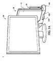
- Fig. 1A shows a computer system of a first embodiment of the invention, wherein a second member of a base is in a first orientation;
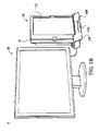
- Fig. 1B shows the computer system of the first embodiment of the invention, wherein the second member of the base is in a second orientation
- Fig 2A shows detailed structure of the base, wherein the second member of the base is in the second orientation
- Fig. 2B is an exploded view of the base
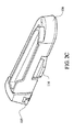
- Fig. 2C shows detailed structure of the base, wherein the second member of the base is in the first orientation
- Fig. 3 shows a base of a modified example of the invention
- Fig. 4 shows a base of a second embodiment of the invention.
- Fig. 5 shows a base of a third embodiment of the invention.
- Figs. 1A and 1B show a computer system 1 of a first embodiment of the invention.
- the computer system 1 includes a portable electronic device 10 (notebook, flat panel computer or other portable computers), an externally connected display 20 (desktop display or other type display) and a base 100.
- the portable electronic device 10 includes a body 11 and a screen 12.
- the screen 12 is connected to the body 11.
- the portable electronic device 10 is electrically connected to the externally connected display 20.
- the base 100 includes a first member 110 and a second member 120, wherein the first member 110 is connected to the second member 120, wherein the second member 120 is pivoted relative to the first member 110 between a first orientation (as shown in Fig. 1A ) and a second orientation (as shown in Fig. 1 B) , and the portable electronic device 10 is detachably disposed on the second member 120.
- the second member 120 when utilizing the computer system 1 of the embodiment, the second member 120 is in the second orientation, and the screen 12 is therefore facing a user.
- the portable electronic device 10 shows an image via the externally connected display 20 and the screen 12.
- a user can select the externally connected display 20 or the screen 12 to show a window.
- a user can modify orientation of the screen 12 of the portable electronic device 10, and the base 100 can sufficiently support the portable electronic device 10.
- Figs. 2A and 2B show detailed structures of the base 100.
- the base 100 further includes a pivot element 130.
- the pivot element 130 includes a first portion 131 and a second portion 132.
- the first portion 131 is connected to the first member 110, and the second portion 132 is connected to the second member 120.
- the first portion 131 is pivoted relative to the second portion 132.
- the pivot element 130 is connected to the first member 110 and the second member 120 by wedging, screw fixing or other means.
- the second member 120 is therefore pivoted relative to the first member 110.
- the second member 120 includes a socket 122, an expansion slot 123, a bottom surface 124 and at least one supporting element 125, The supporting element 125 protrudes from the bottom surface 124.
- the supporting member 125 contacts a supporting surface (for example, desk) to support the base 100.
- the portable electronic device 10 is attached into the socket 122.
- the socket 122 has a notch 1221.
- the screen 12 faces the notch 1221, so that the screen 12 can be fully watched by a user without obstruction by the edge of the socket 122.
- the socket 122 further has a positioning post 1222, a plurality of ribs 1223 and a main connector 1224.
- the ribs 1223 are formed on a side wall of the socket 122.
- the main connector 1224 is disposed in the socket 122.
- the first member 110 has an external connection port 115, and the external connection, port 115 is electrically connected to the externally connected display 20.
- the computer system 1 further comprises an expansion device 30.
- the expansion device 30 is attached into the expansion slot 123.
- the expansion device 30 is electrically connected to the portable electronic device 10 via the base 120.
- the expansion device 30 can be an optical storage device, a portable hard disc, other storage device or other transmission device.
- the second member 120 comprises a protrusion 126
- the second member 110 comprises a first recess 112 and a second recess 113
- the protrusion 126 wedges the first recess 112.
- the protrusion 126 wedges the second recess 113.
- an included angle is formed between the first orientation and the second orientation, and the included angle is between 80°-100°, for example, 90°.
- the number of the recess can be increased allowing the protrusion to position the second member in different orientations.
- Fig. 2C shows a detailed structure of the base 100, wherein the second member 120 of the base 100 is in the first orientation.
- Supporting portions 114 can be formed on the first member 110 to increase stability of the base 100.
- the second member 120 includes a positioning block 126'
- the first member 110 includes a positioning groove 112'
- the positioning block 126' slides in the positioning groove 112'.
- the positioning block 126' abuts an end of the positioning groove 112'.
- the first member 110 is longitudinal, and the second member 120 is connected to an end of the first member 110.
- Fig. 4 shows a base 100' of a second embodiment of the invention.
- the first member 110' is longitudinal, and the second member 120' is connected to a central section of the first member 110'. Similar to the first embodiment, the first member 110' has supporting portions 114' to increase stability of the base 100'.
- Fig. 5 shows a base 100" of a third embodiment of the invention, wherein the first member 110" comprises a first dish structure 119, the second member 120" comprises a second dish structure 129, the second dish structure 129 is correspondingly connected to the first dish structure 119, and the second dish structure 129 rotates relative to the first dish structure 119. Comparing the bases of the first and second embodiments, the base 100" of the third embodiment is more stable when rotated, and has increased dimensions.
Landscapes
- Engineering & Computer Science (AREA)
- Theoretical Computer Science (AREA)
- Computer Hardware Design (AREA)
- Human Computer Interaction (AREA)
- Physics & Mathematics (AREA)
- General Engineering & Computer Science (AREA)
- General Physics & Mathematics (AREA)
- Casings For Electric Apparatus (AREA)
Abstract
Description
- This Application claims priority of Taiwan Patent Application No.
099118873, filed on Jun 10, 2010 - The present invention relates to a computer system, and in particular relates to a computer system with a rotatable base.
- A conventional base of a computer system is utilized so that a computer box can stand upright, wherein the computer box is also prevented from toppling over. Conventionally, the base only provides the function of supporting the computer box. The base is not electrically connected to the computer box. Additionally, when the computer box and the base are arranged on a desk, location of the computer box and the base is permanent.
- The embodiment of the invention provides a base which allows a portable electronic device to be attached thereto. The base includes a first member, a second member and a pivot element. The first member includes an external connection port The second member includes a socket. The pivot element is connected to the first member and the second member, the second member is pivoted relative to the first member between a first orientation and a second orientation via the pivot element, and the portable electronic device is detachably attached into the socket to stand on the second member.
- The embodiment of the invention also provides a computer system including an externally connected display, a portable electronic device and a base. The portable electronic device includes a body and a screen, wherein the screen is connected to the body, and the portable electronic device is electrically connected to the externally connected display. The base includes a first member, a second member and a pivot element, wherein the pivot element is connected to the first member and the second member, the second member is pivoted relative to the first member between a first orientation and a second orientation via the pivot element, and the portable electronic device is detachably attached into the socket to stand on the second member.
- When utilizing the computer system of the embodiment, the second member is in the second orientation, and the screen is therefore facing the user. The portable electronic device shows an image via the externally connected display and the screen. A user can select the externally connected display or the screen to show a window. Utilizing the embodiment of the invention, a user can modify orientation of the screen of the portable electronic device, and the base can sufficiently support the portable electronic device.
- A detailed description is given in the following embodiments with reference to the accompanying drawings.
- The present invention can be more fully understood by reading the subsequent detailed description and examples with references made to the accompanying drawings, wherein:
-
Fig. 1A shows a computer system of a first embodiment of the invention, wherein a second member of a base is in a first orientation; -
Fig. 1B shows the computer system of the first embodiment of the invention, wherein the second member of the base is in a second orientation; -
Fig 2A shows detailed structure of the base, wherein the second member of the base is in the second orientation; -
Fig. 2B is an exploded view of the base; -
Fig. 2C shows detailed structure of the base, wherein the second member of the base is in the first orientation; -
Fig. 3 shows a base of a modified example of the invention; -
Fig. 4 shows a base of a second embodiment of the invention; and -
Fig. 5 shows a base of a third embodiment of the invention. - The following description is of the best-contemplated mode of carrying out the invention. This description is made for the purpose of illustrating the general principles of the invention and should not be taken in a limiting sense. The scope of the invention is best determined by reference to the appended claims.
-
Figs. 1A and1B show acomputer system 1 of a first embodiment of the invention. Thecomputer system 1 includes a portable electronic device 10 (notebook, flat panel computer or other portable computers), an externally connected display 20 (desktop display or other type display) and abase 100. The portableelectronic device 10 includes abody 11 and ascreen 12. Thescreen 12 is connected to thebody 11. The portableelectronic device 10 is electrically connected to the externally connecteddisplay 20. Thebase 100 includes afirst member 110 and asecond member 120, wherein thefirst member 110 is connected to thesecond member 120, wherein thesecond member 120 is pivoted relative to thefirst member 110 between a first orientation (as shown inFig. 1A ) and a second orientation (as shown inFig. 1 B) , and the portableelectronic device 10 is detachably disposed on thesecond member 120. - With reference to
Fig. 1B , when utilizing thecomputer system 1 of the embodiment, thesecond member 120 is in the second orientation, and thescreen 12 is therefore facing a user. The portableelectronic device 10 shows an image via the externally connecteddisplay 20 and thescreen 12. A user can select the externally connecteddisplay 20 or thescreen 12 to show a window. Utilizing the embodiment of the invention, a user can modify orientation of thescreen 12 of the portableelectronic device 10, and thebase 100 can sufficiently support the portableelectronic device 10. -
Figs. 2A and2B show detailed structures of thebase 100. With reference toFig. 2B , thebase 100 further includes apivot element 130. Thepivot element 130 includes afirst portion 131 and asecond portion 132. Thefirst portion 131 is connected to thefirst member 110, and thesecond portion 132 is connected to thesecond member 120. Thefirst portion 131 is pivoted relative to thesecond portion 132. Thepivot element 130 is connected to thefirst member 110 and thesecond member 120 by wedging, screw fixing or other means. Thesecond member 120 is therefore pivoted relative to thefirst member 110. - With reference to
Fig. 2A , thesecond member 120 includes asocket 122, anexpansion slot 123, abottom surface 124 and at least one supportingelement 125, The supportingelement 125 protrudes from thebottom surface 124. When thesecond member 120 is in the second orientation, the supportingmember 125 contacts a supporting surface (for example, desk) to support thebase 100. The portableelectronic device 10 is attached into thesocket 122. Thesocket 122 has anotch 1221. When the portableelectronic device 10 is disposed in thesocket 122, thescreen 12 faces thenotch 1221, so that thescreen 12 can be fully watched by a user without obstruction by the edge of thesocket 122. Thesocket 122 further has apositioning post 1222, a plurality ofribs 1223 and amain connector 1224. Theribs 1223 are formed on a side wall of thesocket 122. Themain connector 1224 is disposed in thesocket 122. When the portableelectronic device 10 is disposed in thesocket 122, thepositioning post 1222 is inserted into the portableelectronic device 10 to position the portableelectronic device 10, theribs 1223 contact the portableelectronic device 10, and themain connector 1224 is electrically connected to the portableelectronic device 10. - In this embodiment, the
first member 110 has anexternal connection port 115, and the external connection,port 115 is electrically connected to the externally connecteddisplay 20. - With reference to
Figs. 1B and2A , thecomputer system 1 further comprises anexpansion device 30. Theexpansion device 30 is attached into theexpansion slot 123. Theexpansion device 30 is electrically connected to the portableelectronic device 10 via thebase 120. Theexpansion device 30 can be an optical storage device, a portable hard disc, other storage device or other transmission device. - With reference to
Fig. 2B , in one embodiment, thesecond member 120 comprises aprotrusion 126, and thesecond member 110 comprises afirst recess 112 and asecond recess 113, When thesecond member 120 is in the first orientation, theprotrusion 126 wedges thefirst recess 112. When thesecond member 120 is in the second orientation, theprotrusion 126 wedges thesecond recess 113. In this embodiment, an included angle is formed between the first orientation and the second orientation, and the included angle is between 80°-100°, for example, 90°. In a modified example, the number of the recess can be increased allowing the protrusion to position the second member in different orientations.Fig. 2C shows a detailed structure of thebase 100, wherein thesecond member 120 of thebase 100 is in the first orientation. - Supporting
portions 114 can be formed on thefirst member 110 to increase stability of thebase 100. - With reference to
Fig. 3 , in a modified example, thesecond member 120 includes a positioning block 126', thefirst member 110 includes a positioning groove 112', and the positioning block 126' slides in the positioning groove 112'. When thesecond member 120 is in the first orientation, the positioning block 126' abuts an end of the positioning groove 112'. - In the first embodiment of the invention, the
first member 110 is longitudinal, and thesecond member 120 is connected to an end of thefirst member 110. -
Fig. 4 shows a base 100' of a second embodiment of the invention. The first member 110' is longitudinal, and the second member 120' is connected to a central section of the first member 110'. Similar to the first embodiment, the first member 110' has supporting portions 114' to increase stability of the base 100'. -
Fig. 5 shows a base 100" of a third embodiment of the invention, wherein thefirst member 110" comprises afirst dish structure 119, thesecond member 120" comprises asecond dish structure 129, thesecond dish structure 129 is correspondingly connected to thefirst dish structure 119, and thesecond dish structure 129 rotates relative to thefirst dish structure 119. Comparing the bases of the first and second embodiments, the base 100" of the third embodiment is more stable when rotated, and has increased dimensions. - While the invention has been described by way of example and in terms of the preferred embodiments, it is to be understood that the invention is not limited to the disclosed embodiments. To the contrary, it is intended to cover various modifications and similar arrangements (as would be apparent to those skilled in the art). Therefore, the scope of the appended claims should be accorded the broadest interpretation so as to encompass all such modifications and similar arrangements.
Claims (19)
- A base which allows a portable electronic device to be attached thereto, comprising:a first member, comprising an external connection port;a second member, comprising a socket; anda pivot element, wherein the pivot element is connected to the first member and the second member, the second member is pivoted relative to the first member between a first orientation and a second orientation via the pivot element, and the portable electronic device is detachably attached into the socket to stand on the second member.
- The base as claimed in claim 1, wherein the pivot element comprises a first portion and a second portion, the first portion is connected to the first member, the second portion is connected to the second member, the first portion is pivoted relative to the second portion, and the pivot element is connected to the first member and the second member by wedging or screw fixing.
- The base as claimed in claim 1, wherein the second member comprises a bottom surface and at least one supporting element, and the supporting element protrudes from the bottom surface.
- The base as claimed in claim 1, wherein the socket has a notch, and when the portable electronic device is attached into the socket, a screen of the portable electronic device faces the notch.
- The base as claimed in claim 1, wherein the socket comprises a positioning post, and when the portable electronic device is attached into the socket, the positioning post is inserted into the portable electronic device.
- The base as claimed in claim 1, wherein the socket comprises a plurality of ribs, the ribs are formed on a wall of the socket, and when the portable electronic device is attached into the socket, the ribs contact the portable electronic device.
- The base as claimed in claim 1, wherein the socket has a main connector disposed therein, and when the portable electronic device is attached into the socket, the main connector is connected to the portable electronic device.
- The base as claimed in claim 1, wherein second member further comprising an expansion slot, an expansion device is attached into the expansion slot, and the expansion device is electrically connected to the portable electronic device via the base.
- The base as claimed in claim 1, wherein the second member comprises a protrusion, the first member comprises a first recess and a second recess, the protrusion wedges the first recess when the second member is in the first orientation, and the protrusion wedges the second recess when the second member is in the second orientation.
- The base as claimed in claim 1, wherein the second member comprises a positioning block, the first member comprises a positioning groove, the positioning block slides in the positioning groove, and when the second member is in the first orientation, the positioning block abuts an end of the positioning groove.
- The base as claimed in claim 1, wherein an included angle between the first orientation and the second orientation is between 80° - 100°.
- The base as claimed in claim 1, wherein the first member is longitudinal, and the second member is connected to an end of the first member.
- The base as claimed in claim 1, wherein the first member is longitudinal, and the second member is connected to a central section of the first member.
- The base as claimed in claim 1, wherein the first member comprises a first dish structure, the second member comprises a second dish structure, the second dish structure is correspondingly connected to the first dish structure, and the second dish structure rotates relative to the first dish structure.
- A computer system, comprising:an externally connected display;a portable electronic device, comprising a body and a screen, wherein the screen is connected to the body, and the portable electronic device is electrically connected to the externally connected display; anda base, comprising a first member, a second member and a pivot element, wherein the pivot element is connected to the first member and the second member, the second member is pivoted relative to the first member between a first orientation and a second orientation via the pivot element, and the portable electronic device is detachably attached into the socket to stand on the second member.
- The computer system as claimed in claim 15, wherein the portable electronic device is electrically connected to the externally connected display via the base.
- The computer system as claimed in claim 15, further comprising an expansion device detachably disposed on the second member, wherein the expansion device is electrically connected to the portable electronic device via the base.
- The computer system as claimed in claim 17, wherein the expansion device is an optical storage device or a portable hard disc.
- The computer system as claimed in claim 15, wherein the portable electronic device is a notebook or a flat panel computer.
Applications Claiming Priority (1)
| Application Number | Priority Date | Filing Date | Title |
|---|---|---|---|
| TW099118873A TWI386582B (en) | 2010-06-10 | 2010-06-10 | Computer system and base structure thereof |
Publications (2)
| Publication Number | Publication Date |
|---|---|
| EP2395410A2 true EP2395410A2 (en) | 2011-12-14 |
| EP2395410A3 EP2395410A3 (en) | 2014-07-02 |
Family
ID=43608058
Family Applications (1)
| Application Number | Title | Priority Date | Filing Date |
|---|---|---|---|
| EP10014598.6A Withdrawn EP2395410A3 (en) | 2010-06-10 | 2010-11-14 | Computer system and docking station thereof |
Country Status (4)
| Country | Link |
|---|---|
| US (1) | US20110304967A1 (en) |
| EP (1) | EP2395410A3 (en) |
| JP (1) | JP2011258176A (en) |
| TW (1) | TWI386582B (en) |
Families Citing this family (7)
| Publication number | Priority date | Publication date | Assignee | Title |
|---|---|---|---|---|
| TWI537704B (en) * | 2010-06-10 | 2016-06-11 | 技嘉科技股份有限公司 | Computer system |
| CN102609055A (en) * | 2011-01-24 | 2012-07-25 | 鸿富锦精密工业(深圳)有限公司 | Notebook computer |
| KR101409465B1 (en) * | 2011-02-08 | 2014-08-13 | 스카이파워텔 주식회사 | stand for portable terminal |
| US20130182387A1 (en) * | 2012-01-16 | 2013-07-18 | Shadi Mere | Accessory system for portable electronic computing devices |
| TWM445327U (en) * | 2012-05-15 | 2013-01-11 | Atrust Comp Corp | Electronic apparatus of composite receive frame |
| US9715248B2 (en) * | 2015-04-27 | 2017-07-25 | Hong Fu Jin Precision Industry (Wuhan) Co., Ltd. | Base for electronic device and electronic device assembly |
| US20220341537A1 (en) * | 2019-11-06 | 2022-10-27 | Hewlett-Packard Development Company, L.P. | Computing device stands and display mount interface spacers |
Citations (3)
| Publication number | Priority date | Publication date | Assignee | Title |
|---|---|---|---|---|
| GB2319290A (en) * | 1996-11-15 | 1998-05-20 | Samsung Electronics Co Ltd | Swivelling device for a liquid crystal display monitor |
| US20060061958A1 (en) * | 2004-09-17 | 2006-03-23 | Mark Solomon | Portable computer docking station |
| US20080165492A1 (en) * | 2007-01-05 | 2008-07-10 | Oqo, Inc. | Docking assembly for a computer and method |
Family Cites Families (58)
| Publication number | Priority date | Publication date | Assignee | Title |
|---|---|---|---|---|
| US5408382A (en) * | 1992-01-10 | 1995-04-18 | Norand Corporation | Terminal and docking mechanism with open channel members and guide rollers |
| JPH0895669A (en) * | 1994-09-29 | 1996-04-12 | Toshiba Corp | Electronic equipment system |
| US5604663A (en) * | 1994-12-27 | 1997-02-18 | Daewoo Telecom Ltd. | Portable computer docking station having a rotatable member and audio speakers mounted on the rotatable member |
| US5769369A (en) * | 1995-04-28 | 1998-06-23 | Meinel; James | Mobile office stand for supporting a portable computer or electronic organizer in vehicles |
| US5687060A (en) * | 1996-06-17 | 1997-11-11 | Compaq Computer Corporation | Vertically oriented docking station apparatus for a portable computer |
| US5875094A (en) * | 1996-08-02 | 1999-02-23 | Compaq Computer Corporation | Portable computer docking station with adjustable insertion angle |
| US6091602A (en) * | 1996-10-03 | 2000-07-18 | Hewlett-Packard Company | Computer docking station for horizontal or vertical positioning |
| KR19980034367A (en) * | 1996-11-03 | 1998-08-05 | 김광호 | Liquid crystal display device having power supply and signal part in the stand part |
| US6282082B1 (en) * | 1998-07-31 | 2001-08-28 | Qubit, Llc | Case for a modular tablet computer system |
| US6493220B1 (en) * | 1998-09-18 | 2002-12-10 | Lxe, Inc. | Mobile clinical workstation |
| US6094347A (en) * | 1999-01-08 | 2000-07-25 | Intel Corporation | Airflow heat exchanger for a portable electronic device and port replicator, docking station, or mini-docking station |
| US6231371B1 (en) * | 1999-06-25 | 2001-05-15 | Hewlett-Packard Company | Docking station for multiple devices |
| JP3078767U (en) * | 1999-09-10 | 2001-07-19 | 株式会社センチュリー | Computer stand |
| USD454131S1 (en) * | 2000-05-19 | 2002-03-05 | Mobility Electronics, Inc. | Docking station |
| KR100428794B1 (en) * | 2000-09-14 | 2004-04-28 | 삼성전자주식회사 | Docking mechanism used for assembling/disassembling peripheral device of computer |
| JP4403218B2 (en) * | 2000-10-19 | 2010-01-27 | レノボ シンガポール プライヴェート リミテッド | Expansion connector device |
| US7038906B2 (en) * | 2001-03-01 | 2006-05-02 | Mds Advertising, Inc. | Portable computer stand with integral communication method and apparatus |
| US6608749B2 (en) * | 2001-03-01 | 2003-08-19 | Mds Advertising, Inc. | Portable computer pedestal method and apparatus |
| US6583984B2 (en) * | 2001-03-23 | 2003-06-24 | Hewlett-Packard Development Company, L.P. | Multi-position computing device docking station |
| DE20106114U1 (en) * | 2001-04-06 | 2001-12-06 | Chang Dean | Angle adjustable bracket for a Personal Digital Assistant for use in an automobile |
| US6926130B2 (en) * | 2001-05-08 | 2005-08-09 | Restech, Inc. | Portable docking station and cord reel assembly |
| US20030072133A1 (en) * | 2001-10-16 | 2003-04-17 | Compal Electronics, Inc. | Auxiliary apparatus for personal digital assistants |
| US6963487B2 (en) * | 2001-10-25 | 2005-11-08 | Hewlett-Packard Development Company, L.P. | Pedestal computer docking station |
| US6683786B2 (en) * | 2002-01-07 | 2004-01-27 | Hewlett-Packard Development Company, L.P. | Portable computer docking station with movable electrical interface |
| JP4360593B2 (en) * | 2002-02-15 | 2009-11-11 | ソニー・エリクソン・モバイルコミュニケーションズ株式会社 | Hinge structure and mobile information terminal device |
| US6643127B1 (en) * | 2002-02-19 | 2003-11-04 | Brian Edward Richardson | In-monitor docking station to integrate a laptop computer into a desktop computer system |
| AU2003228257A1 (en) * | 2002-05-28 | 2003-12-19 | Eric Thompson | Vertical docking station |
| US7542052B2 (en) * | 2002-05-31 | 2009-06-02 | Hewlett-Packard Development Company, L.P. | System and method of switching viewing orientations of a display |
| US6644611B1 (en) * | 2002-06-04 | 2003-11-11 | Mitac Technology Corp. | Adjustable inclined angle structure for computers |
| US7652876B2 (en) * | 2002-06-13 | 2010-01-26 | Gerald Moscovitch | Graphics and monitor controller assemblies in multi-screen display systems |
| US6856506B2 (en) * | 2002-06-19 | 2005-02-15 | Motion Computing | Tablet computing device with three-dimensional docking support |
| US6742221B2 (en) * | 2002-11-06 | 2004-06-01 | Shin Zu Shing Co., Ltd. | Hinge for a notebook computer |
| TWI248017B (en) * | 2003-03-27 | 2006-01-21 | Benq Corp | A display for electronic devices |
| US20060229502A1 (en) * | 2003-06-03 | 2006-10-12 | Bayer Healthcare Llc | Portable medical diagnostic apparatus |
| JP4380266B2 (en) * | 2003-08-29 | 2009-12-09 | ソニー株式会社 | Connection device for electronic equipment |
| TWM245523U (en) * | 2003-11-20 | 2004-10-01 | Tatung Co | Portable computer keyboard expanding base |
| US6937463B2 (en) * | 2004-01-21 | 2005-08-30 | D-Link Corporation | Support having adjustable width |
| CA2459835A1 (en) * | 2004-03-05 | 2005-09-05 | Jvl Corporation | Countertop video terminal |
| DE602004003671T2 (en) * | 2004-03-18 | 2007-10-04 | Bakker & Elkhuizen Holding B.V. | Desktop stand for docking station and portable computer |
| US7133280B2 (en) * | 2004-03-22 | 2006-11-07 | Gateway Inc. | Multiaxial hinge assembly with rotational direction indicator |
| US20050270731A1 (en) * | 2004-06-07 | 2005-12-08 | Memphis-Zhihong Yin | Computer docking system |
| US7708240B2 (en) * | 2004-07-29 | 2010-05-04 | Hewlett-Packard Development Company, L.P. | Computer docking system |
| USD512066S1 (en) * | 2004-08-03 | 2005-11-29 | Hewlett-Packard Development Company, L.P. | Portable computer docking station |
| US20060054751A1 (en) * | 2004-09-15 | 2006-03-16 | Johnson Brian B | Vertically-adjustable mobile computer workstation and method of using same |
| CA108820S (en) * | 2004-09-21 | 2006-01-12 | Toshiba A T A Toshiba Corp Kk | Docking unit for digital audio players |
| US20060221565A1 (en) * | 2005-04-04 | 2006-10-05 | Motion Computing, Inc. | Ultra thin tablet computer battery and docking system |
| US20060262497A1 (en) * | 2005-05-23 | 2006-11-23 | Victor Jahlokov | Apparatus to hold laptop or notebook computer vertically while connected to a full size keyboard, mouse and external monitor |
| US7352567B2 (en) * | 2005-08-09 | 2008-04-01 | Apple Inc. | Methods and apparatuses for docking a portable electronic device that has a planar like configuration and that operates in multiple orientations |
| US7215538B1 (en) * | 2005-10-18 | 2007-05-08 | Shaofen Chen | Portable computer with multi-sectioned arms to support display position adjustment and multiple configurations |
| JP4555241B2 (en) * | 2006-02-27 | 2010-09-29 | 京セラ株式会社 | Mobile terminal device |
| US7684185B2 (en) * | 2006-07-03 | 2010-03-23 | Apple Inc. | Integrated monitor and docking station |
| US7558898B2 (en) * | 2006-08-30 | 2009-07-07 | ACCO Brands Corporation | Port replicating apparatus |
| JP4022247B2 (en) * | 2007-06-20 | 2007-12-12 | 京セラ株式会社 | Mobile terminal device |
| CN101569537B (en) * | 2008-04-29 | 2014-07-09 | Ge医疗系统环球技术有限公司 | Docking station and ultrasonic diagnosis system |
| TWM357831U (en) * | 2008-10-22 | 2009-05-21 | Elitegroup Computer Sys Co Ltd | Swivel notebook |
| US20100213330A1 (en) * | 2009-02-24 | 2010-08-26 | Hewlett-Packard Development Company, L.P. | Computer Stand |
| TWM371250U (en) * | 2009-06-15 | 2009-12-21 | Giga Byte Tech Co Ltd | Notebook computer docking station and assembly of notebook computer and notebook computer docking station |
| TWI537704B (en) * | 2010-06-10 | 2016-06-11 | 技嘉科技股份有限公司 | Computer system |
-
2010
- 2010-06-10 TW TW099118873A patent/TWI386582B/en not_active IP Right Cessation
- 2010-10-06 US US12/899,266 patent/US20110304967A1/en not_active Abandoned
- 2010-10-19 JP JP2010234205A patent/JP2011258176A/en active Pending
- 2010-11-14 EP EP10014598.6A patent/EP2395410A3/en not_active Withdrawn
Patent Citations (3)
| Publication number | Priority date | Publication date | Assignee | Title |
|---|---|---|---|---|
| GB2319290A (en) * | 1996-11-15 | 1998-05-20 | Samsung Electronics Co Ltd | Swivelling device for a liquid crystal display monitor |
| US20060061958A1 (en) * | 2004-09-17 | 2006-03-23 | Mark Solomon | Portable computer docking station |
| US20080165492A1 (en) * | 2007-01-05 | 2008-07-10 | Oqo, Inc. | Docking assembly for a computer and method |
Also Published As
| Publication number | Publication date |
|---|---|
| US20110304967A1 (en) | 2011-12-15 |
| TWI386582B (en) | 2013-02-21 |
| JP2011258176A (en) | 2011-12-22 |
| EP2395410A3 (en) | 2014-07-02 |
| TW201144650A (en) | 2011-12-16 |
Similar Documents
| Publication | Publication Date | Title |
|---|---|---|
| EP2395410A2 (en) | Computer system and docking station thereof | |
| US9274556B2 (en) | Tablet computer stand | |
| US9645608B1 (en) | Portable electronic device | |
| US10402635B2 (en) | Electronic device having supporting component | |
| US9141137B2 (en) | Electronic device with keyboard | |
| US20050057893A1 (en) | Computer with adjustable display | |
| EP2001207A9 (en) | Desktop charger holder | |
| US10487977B2 (en) | Supporting assembly and electronic device using the same | |
| US9215818B2 (en) | Electronic device and hinge structure thereof | |
| US20120063079A1 (en) | Electronic device | |
| US7980737B2 (en) | Electronic device support | |
| US7054145B2 (en) | Mechanism for adjusting a display | |
| US8508933B2 (en) | Docking station and portable computer having the same and a method of connecting the docking station and portable computer | |
| EP2395411A2 (en) | Computer system and docking station thereof | |
| TW201308054A (en) | Electronic device and connecting port thereof | |
| US20050270731A1 (en) | Computer docking system | |
| US20060039122A1 (en) | Data storage system having adjustable display module | |
| US8391014B2 (en) | Expandable computer system and fastening device thereof | |
| US20080266401A1 (en) | Electronic device with variably positionable imaging device | |
| CN102339099B (en) | Computer system and base thereof | |
| CN110703853A (en) | Supporting device | |
| US8885846B2 (en) | Electronic device | |
| CN219392552U (en) | First electronic equipment | |
| CN107577276B (en) | Input device with support structure | |
| US20140096151A1 (en) | Optical disk drive with storage device |
Legal Events
| Date | Code | Title | Description |
|---|---|---|---|
| AK | Designated contracting states |
Kind code of ref document: A2 Designated state(s): AL AT BE BG CH CY CZ DE DK EE ES FI FR GB GR HR HU IE IS IT LI LT LU LV MC MK MT NL NO PL PT RO RS SE SI SK SM TR |
|
| AX | Request for extension of the european patent |
Extension state: BA ME |
|
| PUAI | Public reference made under article 153(3) epc to a published international application that has entered the european phase |
Free format text: ORIGINAL CODE: 0009012 |
|
| RAP1 | Party data changed (applicant data changed or rights of an application transferred) |
Owner name: GIGA-BYTE TECHNOLOGY CO., LTD. |
|
| PUAL | Search report despatched |
Free format text: ORIGINAL CODE: 0009013 |
|
| AK | Designated contracting states |
Kind code of ref document: A3 Designated state(s): AL AT BE BG CH CY CZ DE DK EE ES FI FR GB GR HR HU IE IS IT LI LT LU LV MC MK MT NL NO PL PT RO RS SE SI SK SM TR |
|
| AX | Request for extension of the european patent |
Extension state: BA ME |
|
| RIC1 | Information provided on ipc code assigned before grant |
Ipc: G06F 1/16 20060101AFI20140528BHEP |
|
| STAA | Information on the status of an ep patent application or granted ep patent |
Free format text: STATUS: THE APPLICATION IS DEEMED TO BE WITHDRAWN |
|
| 18D | Application deemed to be withdrawn |
Effective date: 20150106 |