EP2394028B1 - Sealing apparatus at the blade shaft of a rotor stage of an axial turbomachine and the use thereof - Google Patents
Sealing apparatus at the blade shaft of a rotor stage of an axial turbomachine and the use thereof Download PDFInfo
- Publication number
- EP2394028B1 EP2394028B1 EP10710168.5A EP10710168A EP2394028B1 EP 2394028 B1 EP2394028 B1 EP 2394028B1 EP 10710168 A EP10710168 A EP 10710168A EP 2394028 B1 EP2394028 B1 EP 2394028B1
- Authority
- EP
- European Patent Office
- Prior art keywords
- blade
- sealing apparatus
- rotor
- bulkheads
- sealing
- Prior art date
- Legal status (The legal status is an assumption and is not a legal conclusion. Google has not performed a legal analysis and makes no representation as to the accuracy of the status listed.)
- Not-in-force
Links
Images
Classifications
-
- F—MECHANICAL ENGINEERING; LIGHTING; HEATING; WEAPONS; BLASTING
- F01—MACHINES OR ENGINES IN GENERAL; ENGINE PLANTS IN GENERAL; STEAM ENGINES
- F01D—NON-POSITIVE DISPLACEMENT MACHINES OR ENGINES, e.g. STEAM TURBINES
- F01D5/00—Blades; Blade-carrying members; Heating, heat-insulating, cooling or antivibration means on the blades or the members
- F01D5/30—Fixing blades to rotors; Blade roots ; Blade spacers
- F01D5/3007—Fixing blades to rotors; Blade roots ; Blade spacers of axial insertion type
-
- F—MECHANICAL ENGINEERING; LIGHTING; HEATING; WEAPONS; BLASTING
- F05—INDEXING SCHEMES RELATING TO ENGINES OR PUMPS IN VARIOUS SUBCLASSES OF CLASSES F01-F04
- F05D—INDEXING SCHEME FOR ASPECTS RELATING TO NON-POSITIVE-DISPLACEMENT MACHINES OR ENGINES, GAS-TURBINES OR JET-PROPULSION PLANTS
- F05D2260/00—Function
- F05D2260/94—Functionality given by mechanical stress related aspects such as low cycle fatigue [LCF] of high cycle fatigue [HCF]
- F05D2260/941—Functionality given by mechanical stress related aspects such as low cycle fatigue [LCF] of high cycle fatigue [HCF] particularly aimed at mechanical or thermal stress reduction
Definitions
- the present invention relates to a sealing device according to the preamble of claim 1, as in the document DE 37 43 253 A1 described.
- a turbine stage in which the blade roots of the individual blades are equipped with a double-walled bulkhead. Furthermore, the individual blades are held in the axial direction by further sealing plates, which simultaneously seal the Schaufelfzißabites, wherein the further Abdichtplatten are used both at a designated edge of the inner rotor and at one edge of the blade root. Since the sealing plates are also provided as attachment of the blades, they experience high mechanical stresses in both the axial and in the radial direction, which can lead to failure of the sealing properties between the plates as the life progresses.
- the GB 1 295 003 discloses a rotor for a turbomachine having a plurality of blades with blade roots which are positioned at a regular distance by engagement of lateral bimetallic plates on the periphery of a rotor.
- the rotor and the blades to be mounted on a U-shaped edge, in which the bimetallic plates are latched.
- a turbine blade inner end fastener which is attached to the inner rotor.
- the blade inner ends have parts with a hook-like configuration in the region of the blade root, which are received in grooves formed by flanges and arranged at an axial distance along the inner rotor.
- the chopping parts are secured by a locking device by precisely fitting engagement with the grooves, so that radial and axial movements are prevented relative to the rotor housing.
- the blades are arranged one after the other on the rotor, so that open slots can be provided between the individual blades and their attachments.
- extremely small tolerances must be maintained both for the assembly and because of the consideration of the thermal expansion of the components. Pressure losses are therefore not completely ruled out and, moreover, high mechanical stresses on the fastening devices occur, which result in a reduced service life and in a loss of the sealing properties as the service life progresses.
- a seal assembly for the rotor of a turbomachine for sealing between a blade root and a laterally disposed heat shield is known.
- T-shaped sealing elements in designated slots of the blade root and the heat shield added.
- the seal assembly uses sealing elements, which do not serve as fasteners in contrast to the aforementioned prior art.
- the mechanical loads on the sealing elements are reduced, and the sealing properties are no longer so drastically dependent on the service life of the components.
- this method is very time consuming and expensive both in component manufacture and connected during assembly of the blades on the inner rotor. Furthermore, massive and thus heavy components are necessary because of the slots.
- the invention is therefore based on the object to avoid the disadvantages of the known solutions of the prior art and to provide an improved solution for sealing the flow cross-section of a rotor. Furthermore, a solution is to be provided which allows a simple and cost-effective production of the sealing devices for sealing the flow cross section of a rotor, whereby the assembly time of the individual blades is reduced on the rotor and the performance of the turbomachine is increased. At the same time, the mechanical stresses to which the ends of the bulkhead walls are exposed at the blade root should also be reduced and a secure, permanent sealing of the flow cross-section and of a rotor of a turbomachine should be made possible.
- the sealing device according to the invention for sealing the rotor of a turbomachine is located on the blade shank of the rotor blades of a Rotor stage of an axial flow machine, wherein a plurality of blades are arranged in the circumferential direction side by side on the rotor.
- the sealing device has on the blade shank in the axial direction to the front and rear protruding bottom plates and in the radial direction along the blade shank extending bulkheads, which form a double-walled seal in the axial direction.
- the transition cross section from the bottom plates to the bulkheads is preferably rounded, or parabolic.
- at least one of the two bulkhead walls is offset inwardly with respect to the blade root edge at the level of an identical radial distance from the rotor axis in the direction of the radial longitudinal axis of the blade shaft.
- the sealing device also consists of a single solid component.
- two bulkhead walls which are formed in the radial direction and extend from the protruding bottom plates in the direction of the rotor axis, have a total parabolic shape.
- the separately produced components can be connected to one another by welding, for example, and the sealing device can be coated with a friction-reducing coating.
- a sealing device which consists of two interconnected T-pieces and is connected to a blade shank of a blade, a force acts on the outwardly facing plates in a mechanical stress peak in the region of the two T-joints at the base of the blade out.
- the forces that are exerted, inter alia, on the axially protruding bottom plates of the blades result by their overall shape and by the position of the sealing device in a homogeneous distribution of mechanical stresses in the region of the blade airfoil.
- the wall thickness of the bottom plates is greater than the wall thickness of the radial bulkhead walls.
- At least one of the axially protruding bottom plates and the blade foot disc has different inclinations.
- the sealing device according to the invention is thus applicable in a variety of different types of engines. Different inclinations are further provided as adjustment parameters for predetermined expansion slots.
- the paddle table opens in at least one of the protruding bottom plates L-shaped. This achieves a particularly efficient distribution of the forces exerted on the axially protruding bottom plates and a further homogenization of the mechanical stresses in the region of the blade airfoil, in particular if the inclination of the blade shaft and the axially protruding bottom plates are different.
- the paddle table opens into the two protruding bottom plates U-shaped. This achieves a particularly efficient distribution of the forces exerted on the axially protruding bottom plates and a further homogenization of the mechanical stresses in the region of the blade airfoil, in particular if the inclination of the two axially protruding bottom plates is symmetrical.
- the Schaufelfußtisch is formed straight, inclined or curved.
- a straight configuration of the blade root table is particularly advantageous if the bottom plates protruding in the axial direction are likewise formed straight and in the same plane, and in particular if the turbomachine has a constant flow cross section.
- An inclined configuration of the blade root table is particularly advantageous if the bottom plates projecting in the axial direction have different inclinations and / or if the flow cross section of the Turbomachine changes.
- a domed configuration of the blade root table is particularly advantageous for optimally reinforcing the joints in particular configurations of the floor panels and / or the bulkhead walls.
- the blade and the sealing device are integrally formed. This has the advantage that no mounting slots, neither on the blade shank nor on the rotor stage with extremely small tolerances, for the engagement of lateral sealing plates, which would also have to be produced with extremely low tolerances, are necessary. Another advantage is that only a single component at the rotor stage must be arranged during assembly in order to provide a double-walled seal in the circumferential direction.
- the blade and the sealing device form two separate components, which are arranged against one another.
- the separately produced components can be connected to one another by welding, for example, and the sealing device can be coated with a friction-reducing coating.
- the device according to the invention for sealing the flow cross-section of a rotor is used both in turbines and in compressors of gas turbine plants and generally in turbomachines.
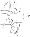
- Fig. 1 shows a part of a rotor, on which a blade is arranged, which contains a preferred embodiment of the invention
- the laterally indicated adjacent to the rotor shaft components 11 have rounded corners and define respective expansion slots 3 for receiving the axially protruding bottom plate 6 of the sealing element 1.
- Each sealing element has a Schaufelfußtisch 8 with two axially projecting bottom plates 6 and two to the center directed to the rotor 5 and connected to the axially projecting bottom plate 6 connected parabolic partition wall 7, 7 '.
- the sealing elements 1 can be regarded as segments of a ring in which the blade root tables 8 are arranged radially, and in which the bulkheads 7,7 'define a double-walled sealing ring disc.
- the sealing ring disc segments are strongly compressed so that no leakage flow can form between the adjacent ends of the individual segments. At the same time, enough space for the expansion caused by the operating temperature in the circumferential direction of the sealing members 1 is left.
- each axially projecting bottom plate 6 is housed in a radially and extending in the circumferential direction of expansion slot 3, which is formed by arranged on the rotor shaft 5 laterally arranged components 11. This already reduces the leakage flow due to the reduced open area.
- the device has a sealing device 2, which contains two parabolic trained bulkheads 7, 7 ', which are offset with respect to the blade root edge 14, 14' in the axial direction to each other.
- a sealing device 2 which contains two parabolic trained bulkheads 7, 7 ', which are offset with respect to the blade root edge 14, 14' in the axial direction to each other.
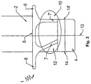
- Fig. 2 shows a longitudinal section through the sealing device 2, according to a first preferred embodiment of the invention.
- the axially protruding bottom plates 6 and the Schaufelfußtisch 8 have the same inclination and are in the same plane.
- the bulkheads 7, 7 ' extending downwardly and radially form with the protruding bottom plates 6 and with the blade root table 8 rounded connections and run in the direction of the rotor axis.
- the wall thickness of the blade root table 8, the bottom plates 6 and the bulkheads 7, 7 ' is the same.
- the sealing device 2 has two differently configured bulkheads 7, 7 '.
- the right in the plane of the bulkhead wall 7 ' is L-shaped and runs parallel to the longitudinal axis 13 of the blade shank 4, while the left in the drawing plane bulkhead 7 in the direction of the longitudinal axis 13 of the blade shank 4 straight and offset with respect to the Schaufelfußrandes 14 inside is.
- the offset 12 of the left in the plane of the bulkhead wall 7 with respect to the Schaufelfußrandes 14 in the direction of the radial longitudinal axis 13 of the blade shank 4 are significantly reduced.
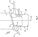
- Fig. 3 shows a longitudinal section through the sealing device 2, according to a second preferred embodiment of the invention.
- the bottom plates 6 protruding in the axial direction and the blade foot table 8 have different Inclinations and lie on different levels.
- the parabolic bulkheads 7, 7 'extending after the rotor center and in the radial direction form parabolic connections with the protruding bottom plates 6 and with the blade root table 8 and extend parabolically in the direction of the rotor axis and subsequently parallel to one another.
- the Schaufelfußtisch 8 also opens here L-shaped in the drawing plane right projecting bottom plate 6.
- the wall thickness of the blade root table 8 and the bottom plates 6 is also greater than the wall thickness of the bulkheads 7, 7 '.
- the right in the plane of the bulkhead wall 7 ' is also in the direction of the longitudinal axis 13 of the blade shank 4 first parabolic and then straight and offset with respect to the Schaufelfußrandes 14' to the inside. Due to the offset 12 of the right in the plane of the bulkhead wall 7 'with respect to the Schaufelfußrandes 14' in the direction of the radial longitudinal axis 13 of the blade shank 4, the voltage peaks at the ends of the bulkheads 7, 7 'on the blade shank 4 are significantly reduced, as a result, the power flow of the introduced Forces is optimized.
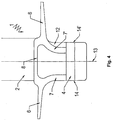
- Fig. 4 shows a longitudinal section through the sealing device 2, according to a third preferred embodiment of the invention.
- the bottom plates 6 projecting in the axial direction and the blade foot table 8 have the same inclination, they are located at different levels.
- the bulkheads 7, 7 ' which extend after the rotor center and in the radial direction and parabolically taper, form rounded connections with the protruding bottom plates 6 and with the blade root table 8 and run parabolically in the direction of the rotor axis.
- the wall thickness of the bulkheads 7, 7 ' greater than the wall thickness of the blade root table 8 and the bottom plates 6.
- the right in the drawing plane bulkhead 7' is also in the direction of the longitudinal axis 13 of the blade shaft 4, ie in the radial direction with respect on the axial flow machine, first parabolic and then rectilinear. In this case, approximately the last third is formed as a straight line in the present embodiment, while the first two thirds of the blade shank 4 form approximately a parabola. With respect to the Schaufelfußrandes 14 'is in the plane of the drawing right bulkhead 7 'offset inside.
Landscapes
- Engineering & Computer Science (AREA)
- Mechanical Engineering (AREA)
- General Engineering & Computer Science (AREA)
- Turbine Rotor Nozzle Sealing (AREA)
Description
Die vorliegende Erfindung betrifft eine Abdichtvorrichtung nach dem Oberbegriff des Anspruchs 1, wie in der Druckschrift
Derartige Abdichtvorrichtungen sind aus dem Stand der Technik bekannt.Such sealing devices are known from the prior art.
In der
Die
Aus der
Aus der
Der Erfindung liegt daher die Aufgabe zugrunde, die Nachteile der bekannten Lösungen des Standes der Technik zu vermeiden und eine verbesserte Lösung zum Abdichten des Strömungsquerschnitts eines Rotors zur Verfügung zu stellen. Ferner soll eine Lösung bereitgestellt werden, welche eine einfache und kostengünstige Herstellung der Abdichtvorrichtungen zum Abdichten des Strömungsquerschnitts eines Rotors ermöglicht, wodurch auch die Montagezeit der einzelnen Schaufeln am Rotor reduziert wird und die Leistung der Strömungsmaschine gesteigert wird. Gleichzeitig sollen die mechanischen Beanspruchungen, welchen die Enden der Schottwände am Schaufelfuß ausgesetzt sind, ebenfalls reduziert werden und eine sichere, dauerhafte Abdichtung des Strömungsquerschnitts sowie eines Rotors einer Strömungsmaschine ermöglicht werden.The invention is therefore based on the object to avoid the disadvantages of the known solutions of the prior art and to provide an improved solution for sealing the flow cross-section of a rotor. Furthermore, a solution is to be provided which allows a simple and cost-effective production of the sealing devices for sealing the flow cross section of a rotor, whereby the assembly time of the individual blades is reduced on the rotor and the performance of the turbomachine is increased. At the same time, the mechanical stresses to which the ends of the bulkhead walls are exposed at the blade root should also be reduced and a secure, permanent sealing of the flow cross-section and of a rotor of a turbomachine should be made possible.
Diese Aufgabe wird erfindungsgemäß durch eine Vorrichtung zum Abdichten des Strömungsquerschnitts eines Rotors einer Strömungsmaschine gemäß den Merkmalen des Anspruchs 1 gelöst. Vorteilhafte Ausführungen der Erfindung sind in den Unteransprüchen beschrieben.This object is achieved by a device for sealing the flow cross-section of a rotor of a turbomachine according to the features of
Die erfindungsgemäße Abdichtvorrichtung zum Abdichten des Rotors einer Strömungsmaschine befindet sich an dem Schaufelschaft der Laufschaufeln einer Rotorstufe einer axialen Strömungsmaschine, wobei mehrere Schaufeln in Umfangsrichtung nebeneinander auf dem Rotor angeordnet sind. Die Abdichtvorrichtung weist am Schaufelschaft in axialer Richtung nach vorne und hinten hervorstehende Bodenplatten und in radialer Richtung sich entlang des Schaufelschafts erstreckenden Schottwände auf, die dabei eine doppelwandige Dichtung in axialer Richtung ausbilden. Der Übergangsquerschnitt von den Bodenplatten zu den Schottwänden ist dabei vorzugsweise abgerundet, bzw. parabolisch ausgebildet. Ferner ist zumindest eine der beiden Schottwände bezüglich des Schaufelfußrandes auf Höhe eines identischen radialen Abstands zur Rotorachse in Richtung der radialen Längsachse des Schaufelschafts nach Innen versetzt.The sealing device according to the invention for sealing the rotor of a turbomachine is located on the blade shank of the rotor blades of a Rotor stage of an axial flow machine, wherein a plurality of blades are arranged in the circumferential direction side by side on the rotor. The sealing device has on the blade shank in the axial direction to the front and rear protruding bottom plates and in the radial direction along the blade shank extending bulkheads, which form a double-walled seal in the axial direction. The transition cross section from the bottom plates to the bulkheads is preferably rounded, or parabolic. Furthermore, at least one of the two bulkhead walls is offset inwardly with respect to the blade root edge at the level of an identical radial distance from the rotor axis in the direction of the radial longitudinal axis of the blade shaft.
Dadurch wird erreicht, dass die Spannungsspitzen, welche durch die Torsion der Schaufel ausgehend vom äußeren Deckband, oder durch Fliehkräfte eingeleitete Spannungen am inneren Deckband oder weitere durch Gaskräfte verursachten Torsionsspannungen, an den Enden der Schottwände am Schaufelfuß reduziert werden. Durch den Versatz von zumindest einer der Schottwände bezüglich des Schaufelfußrandes in Richtung der radialen Längsachse des Schaufelschafts wird außerdem erreicht, dass die Schaufelfußlänge in axialer Richtung verringert wird. Diese Verringerung der Schaufelfußlänge ermöglicht wiederum eine kostengünstigere Herstellung der Bauteile, da weniger Material für das Bauteil notwendig ist, sowie eine gesteigerte Leistung der Strömungsmaschine, da das gesamte Gewicht der Maschine dadurch verringert wird. Ferner wird ein vermindertes Bruch-Risiko im Fall einer vorhandenen Plattenscherung aufgrund des Einflusses hoher Temperaturen und Zentrifugalkräften beim Betrieb der Strömungsmaschine erzielt. Die homogene Verteilung der mechanischen Spannungen am Ansatz der Schaufel bewirkt außerdem eine geringere punktuell konzentrierte Materialbeanspruchung des Bauteils, welche schonend für die Bauteile ist und in einer verlängerten Lebensdauer resultiert. Durch diese Konstruktion besteht die Abdichtvorrichtung außerdem aus einem einzigen massiven Bauteil. Mit der Spannungsreduzierung und der Homogenisierung der mechanischen Spannungen am Schaufelschaftansatz wird es außerdem möglich, die Dicke der Schottwände zu reduzieren, was zu einer weiteren Gewichtsreduzierung und dementsprechend zu einer weiteren Leistungssteigerung der Strömungsmaschine führt. Ferner kann die Höhe des Schaufelschafts ebenfalls reduziert werden.This ensures that the voltage peaks, which are caused by the torsion of the blade, starting from the outer shroud, or by centrifugal forces induced stresses on the inner shroud or other caused by gas forces torsional stresses at the ends of the bulkhead walls on the blade root. By the offset of at least one of the bulkhead walls with respect to the blade root edge in the direction of the radial longitudinal axis of the blade shaft is also achieved that the Schaufelfußlänge is reduced in the axial direction. This reduction in blade root length, in turn, allows for less costly component fabrication because less material is required for the component, as well as increased turbomachine performance, as it reduces the overall weight of the machine. Furthermore, a reduced risk of breakage is achieved in the case of existing plate shear due to the influence of high temperatures and centrifugal forces in the operation of the turbomachine. The homogeneous distribution of the mechanical stresses at the base of the blade also causes a lower concentrated concentrated material stress of the component, which is gentle on the components and results in a prolonged life. By this construction, the sealing device also consists of a single solid component. With the reduction in stress and the homogenization of the mechanical stresses on the blade shank approach, it is also possible to reduce the thickness of the bulkheads, leading to further weight reduction and accordingly leads to a further increase in performance of the turbomachine. Furthermore, the height of the blade shank can also be reduced.
Erfindungsgemäß sind zwei in radialer Richtung ausgebildete Schottwände, die sich von den hervorstehenden Bodenplatten in Richtung der Rotorachse erstrecken, insgesamt parabelförmig ausgebildet.According to the invention, two bulkhead walls, which are formed in the radial direction and extend from the protruding bottom plates in the direction of the rotor axis, have a total parabolic shape.
Durch die Wahl der parabolischen Form des Übergangsquerschnitts an der Verbindung zwischen der Bodenplatte und der radialen Schottwand als auch durch die Wahl der von den hervorstehenden Bodenplatten in Richtung der Rotorachse sich parabolisch erstreckende Schottwand, wird eine optimierte Dichtung geschaffen, welche die mechanischen Spannungen am Ansatz des Schaufelblatts weiter reduziert als auch die homogene Spannungsverteilung der Spannungen am Ansatz unterstützt.By choosing the parabolic shape of the transitional cross section at the connection between the bottom plate and the radial bulkhead, as well as by the choice of the partition wall extending parabolically from the protruding bottom plates in the direction of the rotor axis, an optimized seal is provided, which the mechanical stresses at the neck of Blade further reduced as well as the homogeneous stress distribution of the stresses supported at the neck.
Die getrennt hergestellten Bauteile können beispielsweise durch Schweißen miteinander verbunden werden und die Abdichtvorrichtung mit einer reibungsmindernden Beschichtung beschichtet sein.The separately produced components can be connected to one another by welding, for example, and the sealing device can be coated with a friction-reducing coating.
Stellt man sich eine Abdichtvorrichtung vor, welche aus zwei miteinander verbundenen T-Stücken besteht und an einem Schaufelschaft einer Schaufel verbunden ist, wirkt sich eine Kraft auf den nach außen gerichteten Platten in einer mechanischen Spannungsspitze im Bereich der zwei T-Verbindungen am Ansatz des Schaufelblattes aus. Die Kräfte, welche unter anderem auf die in axialer Richtung hervorstehenden Bodenplatten der Laufschaufeln ausgeübt werden, resultieren dagegen durch ihre gesamte Form und durch die Lage der Abdichtvorrichtung in einer homogenen Verteilung der mechanischen Spannungen im Bereich des Schaufelblattansatzes. In einem weiteren Ausführungsbeispiel der Erfindung ist die Wandstärke der Bodenplatten größer als die Wandstärke der radialen Schottwände. Dadurch wird beispielsweise eine Verstärkung des abgerundeten oder parabolischen Übergangsquerschnittes der Verbindungsstelle mit dem Schaufelfußtisch und mit den radialen Schottwände erreicht und gleichzeitig die Möglichkeit der Anpassung an vorgegebene breitere Ausdehnungsschlitze geschaffen.If one imagines a sealing device which consists of two interconnected T-pieces and is connected to a blade shank of a blade, a force acts on the outwardly facing plates in a mechanical stress peak in the region of the two T-joints at the base of the blade out. The forces that are exerted, inter alia, on the axially protruding bottom plates of the blades, on the other hand result by their overall shape and by the position of the sealing device in a homogeneous distribution of mechanical stresses in the region of the blade airfoil. In a further embodiment of the invention, the wall thickness of the bottom plates is greater than the wall thickness of the radial bulkhead walls. As a result, for example, an amplification of the rounded or parabolic cross-section of the junction with the blade root table and with the achieved radial bulkheads and at the same time created the possibility of adaptation to predetermined wider expansion slots.
In einem weiteren Ausführungsbeispiel der Erfindung besitzt zumindest eine der axial hervorstehenden Bodenplatten und der Schaufelfußtiscb, unterschiedliche Neigungen. Die erfindungsgemäße Abdichtvorrichtung ist somit in einer Vielzahl von verschiedenen Triebwerksarten anwendbar. Unterschiedliche Neigungen sind ferner als Anpassungsparameter für vorgegebene Ausdehnungsschlitze vorgesehen.In another embodiment of the invention, at least one of the axially protruding bottom plates and the blade foot disc has different inclinations. The sealing device according to the invention is thus applicable in a variety of different types of engines. Different inclinations are further provided as adjustment parameters for predetermined expansion slots.
In einem weiteren Ausführungsbeispiel der Erfindung mündet der Schaufeltisch in zumindest einer der hervorstehenden Bodenplatten L-förmig ein. Dadurch wird eine besonders effiziente Verteilung der an den axial hervorstehenden Bodenplatten ausgeübten Kräfte und eine weitere Homogenisierung der mechanischen Spannungen im Bereich des Schaufelblattansatzes erzielt, insbesondere wenn die Neigung des Schaufelschafts und der axial hervorstehenden Bodenplatten unterschiedlich sind.In a further embodiment of the invention, the paddle table opens in at least one of the protruding bottom plates L-shaped. This achieves a particularly efficient distribution of the forces exerted on the axially protruding bottom plates and a further homogenization of the mechanical stresses in the region of the blade airfoil, in particular if the inclination of the blade shaft and the axially protruding bottom plates are different.
In einem weiteren Ausführungsbeispiel der Erfindung mündet der Schaufeltisch in die zwei hervorstehenden Bodenplatten U-formig ein. Dadurch wird eine besonders effiziente Verteilung der an den axial hervorstehenden Bodenplatten ausgeübten Kräfte und eine weitere Homogenisierung der mechanischen Spannungen im Bereich des Schaufelblattansatzes erzielt, insbesondere wenn die Neigung der zwei axial hervorstehenden Bodenplatten symmetrisch ist.In a further embodiment of the invention, the paddle table opens into the two protruding bottom plates U-shaped. This achieves a particularly efficient distribution of the forces exerted on the axially protruding bottom plates and a further homogenization of the mechanical stresses in the region of the blade airfoil, in particular if the inclination of the two axially protruding bottom plates is symmetrical.
In einem anderen vorteilhaften Ausführungsbeispiel der Erfindung wird der Schaufelfußtisch gerade, geneigt oder gewölbt ausgebildet. Eine gerade Konfiguration des Schaufelfußtisches ist besonders vorteilhaft, wenn die in axialer Richtung hervorstehenden Bodenplatten ebenfalls gerade und in der gleichen Ebene ausgebildet sind, und insbesondere dann wenn die Strömungsmaschine einen konstanten Strömungsquerschnitt aufweist. Eine geneigte Konfiguration des Schaufelfußtisches ist besonders vorteilhaft wenn die in axialer Richtung hervorstehenden Bodenplatten unterschiedliche Neigungen aufweisen und/oder wenn der Strömungsquerschnitt der Strömungsmaschine sich ändert. Eine gewölbte Konfiguration des Schaufelfußtisches ist besonders vorteilhaft, um in speziellen Konfigurationen der Bodenplatten und/oder der Schottwände die Verbindungsstellen optimal zu verstärken.In another advantageous embodiment of the invention, the Schaufelfußtisch is formed straight, inclined or curved. A straight configuration of the blade root table is particularly advantageous if the bottom plates protruding in the axial direction are likewise formed straight and in the same plane, and in particular if the turbomachine has a constant flow cross section. An inclined configuration of the blade root table is particularly advantageous if the bottom plates projecting in the axial direction have different inclinations and / or if the flow cross section of the Turbomachine changes. A domed configuration of the blade root table is particularly advantageous for optimally reinforcing the joints in particular configurations of the floor panels and / or the bulkhead walls.
In einem anderen vorteilhaften Ausführungsbeispiel der Erfindung sind die Schaufel und die Abdichtvorrichtung einstückig ausgebildet. Dies hat den Vorteil, dass keine Befestigungsschlitze, weder am Schaufelschaft noch an der Rotorstufe mit äußerst geringen Toleranzen, für das Einklinken von seitlichen Abdichtplatten, die ebenfalls mit äußerst geringen Toleranzen hergestellt werden müssten, notwendig sind. Ein weiterer Vorteil besteht darin, dass bei der Montage nur noch ein einziges Bauteil an der Rotorstufe angeordnet werden muss, um eine in Umfangsrichtung doppelwandige Dichtung bereitzustellen.In another advantageous embodiment of the invention, the blade and the sealing device are integrally formed. This has the advantage that no mounting slots, neither on the blade shank nor on the rotor stage with extremely small tolerances, for the engagement of lateral sealing plates, which would also have to be produced with extremely low tolerances, are necessary. Another advantage is that only a single component at the rotor stage must be arranged during assembly in order to provide a double-walled seal in the circumferential direction.
In einem anderen vorteilhaften Ausführungsbeispiel der Erfindung bilden die Schaufel und die Abdichtvorrichtung zwei getrennte Bauteile, welche aneinander angeordnet werden. Die getrennt hergestellten Bauteile können beispielsweise durch Schweißen miteinander verbunden werden und die Abdichtvorrichtung mit einer reibungsmindernden Beschichtung beschichtet sein.In another advantageous embodiment of the invention, the blade and the sealing device form two separate components, which are arranged against one another. The separately produced components can be connected to one another by welding, for example, and the sealing device can be coated with a friction-reducing coating.
Die erfindungsgemäße Vorrichtung zum Abdichten des Strömungsquerschnitts eines Rotors findet sowohl in Turbinen als auch in Verdichtern von Gasturbinenanlagen und im Allgemeinen in Strömungsmaschinen Verwendung.The device according to the invention for sealing the flow cross-section of a rotor is used both in turbines and in compressors of gas turbine plants and generally in turbomachines.
Vorteilhafte Ausführungsbeispiele der Erfindung werden zusammen mit den Zeichnungen dargestellt und im folgenden näher beschrieben.Advantageous embodiments of the invention will be illustrated together with the drawings and described in more detail below.
Es zeigt:
- Fig. 1
- einen schematischen Längsschnitt durch einen Abschnitt einer Rotorstufe 5, die
eine Abdichtvorrichtung 2 gemäß der vorliegenden Erfindung enthält; - Fig. 2
- einen schematischen Längsschnitt durch die
Abdichtvorrichtung 2 gemäß dem ersten vorteilhaften Ausführungsbeispiel der Erfindung; - Fig. 3
- einen schematischen Längsschnitt durch die
Abdichtvorrichtung 2 gemäß dem zweiten vorteilhaften Ausführungsbeispiel der Erfindung; - Fig. 4
- einen schematischen Längsschnitt durch die
Abdichtvorrichtung 2 gemäß dem dritten vorteilhaften Ausführungsbeispiel der Erfindung.
- Fig. 1
- a schematic longitudinal section through a portion of a
rotor stage 5, which includes asealing device 2 according to the present invention; - Fig. 2
- a schematic longitudinal section through the
sealing device 2 according to the first advantageous embodiment of the invention; - Fig. 3
- a schematic longitudinal section through the
sealing device 2 according to the second advantageous embodiment of the invention; - Fig. 4
- a schematic longitudinal section through the
sealing device 2 according to the third advantageous embodiment of the invention.
Claims (9)
- Sealing apparatus (2) at a blade shaft (4) of a rotor stage of an axial turbomachine, wherein a plurality of blades is arranged next to each other on a rotor (5) in the circumferential direction, and wherein the sealing apparatus (2) has base plates (6) protruding in the axial direction on the blade shaft (4) and bulkheads (7, 7') extending in the radial direction along the blade shaft (4), which bulkheads form a double-walled seal (10) in the axial direction, wherein from the bottom plate (6) to the bulkhead (7, 7'), a rounded or a parabolic transitional cross section is provided, wherein at least one of the bulkheads (7, 7') is offset in relation to a blade root edge (14, 14') in the direction of the radial longitudinal axis (13) of the blade shaft (4), characterised in that at least one of the bulkheads (7, 7') is formed to be parabolic in the direction of the rotor axis.
- The sealing apparatus (2) as claimed in claim 1, characterised in that the wall thickness of the bottom plate (6) is greater than the wall thickness of the radial bulkheads (7, 7').
- The sealing apparatus (2) as claimed in any one of patent claims 1 to 2, characterised in that a blade root table (8) and at least one of the two bottom plates (6) have different inclinations.
- The sealing apparatus (2) as claimed in patent claim 3, characterised in that the transition of the blade root table (8) into at least one of the protruding bottom plates (6) is formed by a rounded L-shaped connection.
- The sealing apparatus (2) as claimed in any one of patent claims 3 to 4, characterised in that the transition of the blade root table (8) into the protruding bottom plates (6) is formed by a rounded U-shaped connection.
- The sealing apparatus (2) as claimed in any one of patent claims 3 to 5, characterised in that the blade root table (8) is formed to be straight, inclined or curved.
- The sealing apparatus (2) as claimed in any one of patent claims 1 to 6, characterised in that the sealing apparatus (2) is formed to be integral with the blade.
- The sealing apparatus (2) as claimed in any one of patent claims 1 to 7, characterised in that the sealing apparatus (2) and the blade are formed as two separate components.
- The use of the sealing apparatus (2) as claimed in any one of the preceding claims in a gas turbine.
Applications Claiming Priority (2)
| Application Number | Priority Date | Filing Date | Title |
|---|---|---|---|
| DE102009007664A DE102009007664A1 (en) | 2009-02-05 | 2009-02-05 | Sealing device on the blade shank of a rotor stage of an axial flow machine |
| PCT/DE2010/000105 WO2010088881A1 (en) | 2009-02-05 | 2010-02-02 | Sealing apparatus at the blade shaft of a rotor stage of an axial turbomachine |
Publications (2)
| Publication Number | Publication Date |
|---|---|
| EP2394028A1 EP2394028A1 (en) | 2011-12-14 |
| EP2394028B1 true EP2394028B1 (en) | 2016-06-01 |
Family
ID=42126369
Family Applications (1)
| Application Number | Title | Priority Date | Filing Date |
|---|---|---|---|
| EP10710168.5A Not-in-force EP2394028B1 (en) | 2009-02-05 | 2010-02-02 | Sealing apparatus at the blade shaft of a rotor stage of an axial turbomachine and the use thereof |
Country Status (5)
| Country | Link |
|---|---|
| US (1) | US8870542B2 (en) |
| EP (1) | EP2394028B1 (en) |
| DE (1) | DE102009007664A1 (en) |
| ES (1) | ES2576125T3 (en) |
| WO (1) | WO2010088881A1 (en) |
Families Citing this family (5)
| Publication number | Priority date | Publication date | Assignee | Title |
|---|---|---|---|---|
| EP2597266B1 (en) | 2011-11-22 | 2014-08-27 | MTU Aero Engines GmbH | Rotor blade and flow machine |
| FR2997723B1 (en) * | 2012-11-06 | 2018-09-21 | Safran Aircraft Engines | AUBE AT FOOT WITH PORTIONS IN LOW |
| US9353629B2 (en) * | 2012-11-30 | 2016-05-31 | Solar Turbines Incorporated | Turbine blade apparatus |
| FR3004484B1 (en) * | 2013-04-11 | 2017-09-08 | Snecma | TURBOMACHINE DAWN COOPERATING WITH AUBES RETENTION DISC |
| ES2718127T3 (en) | 2013-06-27 | 2019-06-27 | MTU Aero Engines AG | Turbine blade of turbomachine and respective turbomachine |
Family Cites Families (21)
| Publication number | Priority date | Publication date | Assignee | Title |
|---|---|---|---|---|
| NL192865A (en) * | 1953-12-02 | |||
| GB1148339A (en) * | 1966-10-20 | 1969-04-10 | Rolls Royce | Compressors or turbines for gas turbine engines |
| GB1295003A (en) | 1971-06-15 | 1972-11-01 | ||
| FR2485632B1 (en) | 1980-06-30 | 1985-07-05 | Snecma | IMPROVEMENT IN VENTILATION SYSTEMS OF BLADES AND TURBINE DISCS |
| US4536129A (en) * | 1984-06-15 | 1985-08-20 | United Technologies Corporation | Turbine blade with disk rim shield |
| FR2586061B1 (en) * | 1985-08-08 | 1989-06-09 | Snecma | MULTIFUNCTIONAL LABYRINTH DISC FOR TURBOMACHINE ROTOR |
| DE3743253A1 (en) | 1987-12-19 | 1989-06-29 | Mtu Muenchen Gmbh | AXIAL FLOWED BLADE BLADES FOR COMPRESSORS OR TURBINES |
| US5131814A (en) | 1990-04-03 | 1992-07-21 | General Electric Company | Turbine blade inner end attachment structure |
| US5302085A (en) * | 1992-02-03 | 1994-04-12 | General Electric Company | Turbine blade damper |
| US5443365A (en) | 1993-12-02 | 1995-08-22 | General Electric Company | Fan blade for blade-out protection |
| JPH08121106A (en) * | 1994-10-26 | 1996-05-14 | Mitsubishi Heavy Ind Ltd | Turbine moving blade |
| GB2302711A (en) | 1995-06-26 | 1997-01-29 | Bmw Rolls Royce Gmbh | A turbine disc with blade seal plates |
| JP2002544430A (en) * | 1999-05-14 | 2002-12-24 | シーメンス アクチエンゲゼルシヤフト | Fluid machinery with leak-proof device for rotor, especially gas turbine |
| EP1371814A1 (en) | 2002-06-11 | 2003-12-17 | ALSTOM (Switzerland) Ltd | Sealing arrangement for a rotor of a turbomachine |
| US7244104B2 (en) * | 2005-05-31 | 2007-07-17 | Pratt & Whitney Canada Corp. | Deflectors for controlling entry of fluid leakage into the working fluid flowpath of a gas turbine engine |
| US7334983B2 (en) * | 2005-10-27 | 2008-02-26 | United Technologies Corporation | Integrated bladed fluid seal |
| DE102005059084A1 (en) * | 2005-12-10 | 2007-06-14 | Mtu Aero Engines Gmbh | Turbomachine, in particular gas turbine |
| US7575416B2 (en) * | 2006-05-18 | 2009-08-18 | United Technologies Corporation | Rotor assembly for a rotary machine |
| EP1898049B1 (en) | 2006-09-11 | 2012-05-23 | Siemens Aktiengesellschaft | Turbine blade |
| US20080101937A1 (en) | 2006-10-26 | 2008-05-01 | General Electric | Blade/disk dovetail backcut for blade/disk stress reduction (9FA, stage 1) |
| FR2918103B1 (en) * | 2007-06-27 | 2013-09-27 | Snecma | DEVICE FOR COOLING ALVEOLES OF A TURBOMACHINE ROTOR DISK. |
-
2009
- 2009-02-05 DE DE102009007664A patent/DE102009007664A1/en active Pending
-
2010
- 2010-02-02 WO PCT/DE2010/000105 patent/WO2010088881A1/en active Application Filing
- 2010-02-02 ES ES10710168.5T patent/ES2576125T3/en active Active
- 2010-02-02 EP EP10710168.5A patent/EP2394028B1/en not_active Not-in-force
- 2010-02-02 US US13/148,026 patent/US8870542B2/en active Active
Non-Patent Citations (1)
| Title |
|---|
| None * |
Also Published As
| Publication number | Publication date |
|---|---|
| ES2576125T3 (en) | 2016-07-05 |
| DE102009007664A1 (en) | 2010-08-12 |
| WO2010088881A1 (en) | 2010-08-12 |
| US20110293408A1 (en) | 2011-12-01 |
| US8870542B2 (en) | 2014-10-28 |
| EP2394028A1 (en) | 2011-12-14 |
Similar Documents
| Publication | Publication Date | Title |
|---|---|---|
| EP2399004B1 (en) | Rotor section for a rotor of a turbo machine, rotor blade for a turbo machine and blocking element | |
| EP2478186B1 (en) | Rotor of a turbomachine | |
| EP3409899B1 (en) | Sealing arrangement with a welded seal sheet, turbo-machine and production method | |
| EP2394028B1 (en) | Sealing apparatus at the blade shaft of a rotor stage of an axial turbomachine and the use thereof | |
| EP3999717B1 (en) | Intermediate element for a blade to-rotor disk connection for a rotor of a turbomachine, rotor for a turbomachine and turbomachine | |
| DE3148985C2 (en) | ROTOR ASSEMBLY | |
| EP1653049B1 (en) | Vane ring assembly for gas turbines and method to modify the same | |
| EP2268902B1 (en) | Strut for an intermediate turbine housing and intermediate turbine housing | |
| EP3287608B1 (en) | Internal ring for a guide- blade rim of a turbomachine | |
| EP2410131B1 (en) | Rotor of a turbomachine | |
| EP2787178B1 (en) | Guide vane assembly | |
| EP2762684B1 (en) | Seal mount made from titanium aluminide for a flow machine | |
| EP3309359B1 (en) | Blade assembly for a gas turbine engine | |
| EP2696039B1 (en) | Gas turbine stage | |
| EP2526263B1 (en) | Housing system for an axial turbomachine | |
| EP3401504A1 (en) | Blade grid | |
| EP3425170A2 (en) | Turbomachine seal element | |
| EP3109520B1 (en) | Seal carrier, guide blade assembly and fluid flow engine | |
| EP3704386B1 (en) | Intermediate duct to be placed between a low pressure compressor and a high pressure compressor, made by additive manufacturing, and corresponding manufacturing method | |
| EP3312388A1 (en) | Pultdach dichtfin | |
| EP2860352A1 (en) | Rotor, corresponding manufacturing method and blade | |
| WO2003100220A1 (en) | Axial securing means for impeller blades | |
| EP3536913A1 (en) | Inner ring for a turbomachine and method for producing said inner ring | |
| EP2873808B1 (en) | Rotor-blade group, method and flow engine | |
| EP2886799A1 (en) | Blade ring for a turbomachine and method for mounting blades of a blade ring of a turbomachine |
Legal Events
| Date | Code | Title | Description |
|---|---|---|---|
| PUAI | Public reference made under article 153(3) epc to a published international application that has entered the european phase |
Free format text: ORIGINAL CODE: 0009012 |
|
| 17P | Request for examination filed |
Effective date: 20110523 |
|
| AK | Designated contracting states |
Kind code of ref document: A1 Designated state(s): AT BE BG CH CY CZ DE DK EE ES FI FR GB GR HR HU IE IS IT LI LT LU LV MC MK MT NL NO PL PT RO SE SI SK SM TR |
|
| DAX | Request for extension of the european patent (deleted) | ||
| RAP1 | Party data changed (applicant data changed or rights of an application transferred) |
Owner name: MTU AERO ENGINES AG |
|
| 17Q | First examination report despatched |
Effective date: 20141217 |
|
| GRAP | Despatch of communication of intention to grant a patent |
Free format text: ORIGINAL CODE: EPIDOSNIGR1 |
|
| INTG | Intention to grant announced |
Effective date: 20160311 |
|
| GRAS | Grant fee paid |
Free format text: ORIGINAL CODE: EPIDOSNIGR3 |
|
| GRAA | (expected) grant |
Free format text: ORIGINAL CODE: 0009210 |
|
| AK | Designated contracting states |
Kind code of ref document: B1 Designated state(s): AT BE BG CH CY CZ DE DK EE ES FI FR GB GR HR HU IE IS IT LI LT LU LV MC MK MT NL NO PL PT RO SE SI SK SM TR |
|
| REG | Reference to a national code |
Ref country code: GB Ref legal event code: FG4D Free format text: NOT ENGLISH |
|
| REG | Reference to a national code |
Ref country code: CH Ref legal event code: EP Ref country code: AT Ref legal event code: REF Ref document number: 804002 Country of ref document: AT Kind code of ref document: T Effective date: 20160615 |
|
| REG | Reference to a national code |
Ref country code: IE Ref legal event code: FG4D Free format text: LANGUAGE OF EP DOCUMENT: GERMAN |
|
| REG | Reference to a national code |
Ref country code: ES Ref legal event code: FG2A Ref document number: 2576125 Country of ref document: ES Kind code of ref document: T3 Effective date: 20160705 |
|
| REG | Reference to a national code |
Ref country code: DE Ref legal event code: R096 Ref document number: 502010011771 Country of ref document: DE |
|
| REG | Reference to a national code |
Ref country code: LT Ref legal event code: MG4D |
|
| REG | Reference to a national code |
Ref country code: NL Ref legal event code: MP Effective date: 20160601 |
|
| PG25 | Lapsed in a contracting state [announced via postgrant information from national office to epo] |
Ref country code: NO Free format text: LAPSE BECAUSE OF FAILURE TO SUBMIT A TRANSLATION OF THE DESCRIPTION OR TO PAY THE FEE WITHIN THE PRESCRIBED TIME-LIMIT Effective date: 20160901 Ref country code: FI Free format text: LAPSE BECAUSE OF FAILURE TO SUBMIT A TRANSLATION OF THE DESCRIPTION OR TO PAY THE FEE WITHIN THE PRESCRIBED TIME-LIMIT Effective date: 20160601 Ref country code: LT Free format text: LAPSE BECAUSE OF FAILURE TO SUBMIT A TRANSLATION OF THE DESCRIPTION OR TO PAY THE FEE WITHIN THE PRESCRIBED TIME-LIMIT Effective date: 20160601 |
|
| PG25 | Lapsed in a contracting state [announced via postgrant information from national office to epo] |
Ref country code: LV Free format text: LAPSE BECAUSE OF FAILURE TO SUBMIT A TRANSLATION OF THE DESCRIPTION OR TO PAY THE FEE WITHIN THE PRESCRIBED TIME-LIMIT Effective date: 20160601 Ref country code: SE Free format text: LAPSE BECAUSE OF FAILURE TO SUBMIT A TRANSLATION OF THE DESCRIPTION OR TO PAY THE FEE WITHIN THE PRESCRIBED TIME-LIMIT Effective date: 20160601 Ref country code: GR Free format text: LAPSE BECAUSE OF FAILURE TO SUBMIT A TRANSLATION OF THE DESCRIPTION OR TO PAY THE FEE WITHIN THE PRESCRIBED TIME-LIMIT Effective date: 20160902 Ref country code: HR Free format text: LAPSE BECAUSE OF FAILURE TO SUBMIT A TRANSLATION OF THE DESCRIPTION OR TO PAY THE FEE WITHIN THE PRESCRIBED TIME-LIMIT Effective date: 20160601 Ref country code: NL Free format text: LAPSE BECAUSE OF FAILURE TO SUBMIT A TRANSLATION OF THE DESCRIPTION OR TO PAY THE FEE WITHIN THE PRESCRIBED TIME-LIMIT Effective date: 20160601 |
|
| PG25 | Lapsed in a contracting state [announced via postgrant information from national office to epo] |
Ref country code: SK Free format text: LAPSE BECAUSE OF FAILURE TO SUBMIT A TRANSLATION OF THE DESCRIPTION OR TO PAY THE FEE WITHIN THE PRESCRIBED TIME-LIMIT Effective date: 20160601 Ref country code: IT Free format text: LAPSE BECAUSE OF FAILURE TO SUBMIT A TRANSLATION OF THE DESCRIPTION OR TO PAY THE FEE WITHIN THE PRESCRIBED TIME-LIMIT Effective date: 20160601 Ref country code: IS Free format text: LAPSE BECAUSE OF FAILURE TO SUBMIT A TRANSLATION OF THE DESCRIPTION OR TO PAY THE FEE WITHIN THE PRESCRIBED TIME-LIMIT Effective date: 20161001 Ref country code: CZ Free format text: LAPSE BECAUSE OF FAILURE TO SUBMIT A TRANSLATION OF THE DESCRIPTION OR TO PAY THE FEE WITHIN THE PRESCRIBED TIME-LIMIT Effective date: 20160601 Ref country code: RO Free format text: LAPSE BECAUSE OF FAILURE TO SUBMIT A TRANSLATION OF THE DESCRIPTION OR TO PAY THE FEE WITHIN THE PRESCRIBED TIME-LIMIT Effective date: 20160601 Ref country code: EE Free format text: LAPSE BECAUSE OF FAILURE TO SUBMIT A TRANSLATION OF THE DESCRIPTION OR TO PAY THE FEE WITHIN THE PRESCRIBED TIME-LIMIT Effective date: 20160601 |
|
| REG | Reference to a national code |
Ref country code: FR Ref legal event code: PLFP Year of fee payment: 8 |
|
| PG25 | Lapsed in a contracting state [announced via postgrant information from national office to epo] |
Ref country code: SM Free format text: LAPSE BECAUSE OF FAILURE TO SUBMIT A TRANSLATION OF THE DESCRIPTION OR TO PAY THE FEE WITHIN THE PRESCRIBED TIME-LIMIT Effective date: 20160601 Ref country code: PL Free format text: LAPSE BECAUSE OF FAILURE TO SUBMIT A TRANSLATION OF THE DESCRIPTION OR TO PAY THE FEE WITHIN THE PRESCRIBED TIME-LIMIT Effective date: 20160601 Ref country code: PT Free format text: LAPSE BECAUSE OF FAILURE TO SUBMIT A TRANSLATION OF THE DESCRIPTION OR TO PAY THE FEE WITHIN THE PRESCRIBED TIME-LIMIT Effective date: 20161003 |
|
| REG | Reference to a national code |
Ref country code: DE Ref legal event code: R097 Ref document number: 502010011771 Country of ref document: DE |
|
| PLBE | No opposition filed within time limit |
Free format text: ORIGINAL CODE: 0009261 |
|
| STAA | Information on the status of an ep patent application or granted ep patent |
Free format text: STATUS: NO OPPOSITION FILED WITHIN TIME LIMIT |
|
| 26N | No opposition filed |
Effective date: 20170302 |
|
| PG25 | Lapsed in a contracting state [announced via postgrant information from national office to epo] |
Ref country code: BE Free format text: LAPSE BECAUSE OF NON-PAYMENT OF DUE FEES Effective date: 20170228 Ref country code: SI Free format text: LAPSE BECAUSE OF FAILURE TO SUBMIT A TRANSLATION OF THE DESCRIPTION OR TO PAY THE FEE WITHIN THE PRESCRIBED TIME-LIMIT Effective date: 20160601 Ref country code: DK Free format text: LAPSE BECAUSE OF FAILURE TO SUBMIT A TRANSLATION OF THE DESCRIPTION OR TO PAY THE FEE WITHIN THE PRESCRIBED TIME-LIMIT Effective date: 20160601 |
|
| PG25 | Lapsed in a contracting state [announced via postgrant information from national office to epo] |
Ref country code: MC Free format text: LAPSE BECAUSE OF FAILURE TO SUBMIT A TRANSLATION OF THE DESCRIPTION OR TO PAY THE FEE WITHIN THE PRESCRIBED TIME-LIMIT Effective date: 20160601 |
|
| REG | Reference to a national code |
Ref country code: CH Ref legal event code: PL |
|
| PG25 | Lapsed in a contracting state [announced via postgrant information from national office to epo] |
Ref country code: CH Free format text: LAPSE BECAUSE OF NON-PAYMENT OF DUE FEES Effective date: 20170228 Ref country code: LI Free format text: LAPSE BECAUSE OF NON-PAYMENT OF DUE FEES Effective date: 20170228 |
|
| REG | Reference to a national code |
Ref country code: IE Ref legal event code: MM4A |
|
| PG25 | Lapsed in a contracting state [announced via postgrant information from national office to epo] |
Ref country code: LU Free format text: LAPSE BECAUSE OF NON-PAYMENT OF DUE FEES Effective date: 20170202 |
|
| REG | Reference to a national code |
Ref country code: BE Ref legal event code: MM Effective date: 20170228 |
|
| REG | Reference to a national code |
Ref country code: FR Ref legal event code: PLFP Year of fee payment: 9 |
|
| PG25 | Lapsed in a contracting state [announced via postgrant information from national office to epo] |
Ref country code: IE Free format text: LAPSE BECAUSE OF NON-PAYMENT OF DUE FEES Effective date: 20170202 |
|
| REG | Reference to a national code |
Ref country code: AT Ref legal event code: MM01 Ref document number: 804002 Country of ref document: AT Kind code of ref document: T Effective date: 20170202 |
|
| PG25 | Lapsed in a contracting state [announced via postgrant information from national office to epo] |
Ref country code: AT Free format text: LAPSE BECAUSE OF NON-PAYMENT OF DUE FEES Effective date: 20170202 |
|
| PG25 | Lapsed in a contracting state [announced via postgrant information from national office to epo] |
Ref country code: MT Free format text: LAPSE BECAUSE OF FAILURE TO SUBMIT A TRANSLATION OF THE DESCRIPTION OR TO PAY THE FEE WITHIN THE PRESCRIBED TIME-LIMIT Effective date: 20160601 |
|
| PG25 | Lapsed in a contracting state [announced via postgrant information from national office to epo] |
Ref country code: HU Free format text: LAPSE BECAUSE OF FAILURE TO SUBMIT A TRANSLATION OF THE DESCRIPTION OR TO PAY THE FEE WITHIN THE PRESCRIBED TIME-LIMIT; INVALID AB INITIO Effective date: 20100202 |
|
| PG25 | Lapsed in a contracting state [announced via postgrant information from national office to epo] |
Ref country code: BG Free format text: LAPSE BECAUSE OF FAILURE TO SUBMIT A TRANSLATION OF THE DESCRIPTION OR TO PAY THE FEE WITHIN THE PRESCRIBED TIME-LIMIT Effective date: 20160601 |
|
| PG25 | Lapsed in a contracting state [announced via postgrant information from national office to epo] |
Ref country code: CY Free format text: LAPSE BECAUSE OF NON-PAYMENT OF DUE FEES Effective date: 20160601 |
|
| PG25 | Lapsed in a contracting state [announced via postgrant information from national office to epo] |
Ref country code: MK Free format text: LAPSE BECAUSE OF FAILURE TO SUBMIT A TRANSLATION OF THE DESCRIPTION OR TO PAY THE FEE WITHIN THE PRESCRIBED TIME-LIMIT Effective date: 20160601 |
|
| PG25 | Lapsed in a contracting state [announced via postgrant information from national office to epo] |
Ref country code: TR Free format text: LAPSE BECAUSE OF FAILURE TO SUBMIT A TRANSLATION OF THE DESCRIPTION OR TO PAY THE FEE WITHIN THE PRESCRIBED TIME-LIMIT Effective date: 20160601 |
|
| PGFP | Annual fee paid to national office [announced via postgrant information from national office to epo] |
Ref country code: DE Payment date: 20200220 Year of fee payment: 11 Ref country code: ES Payment date: 20200320 Year of fee payment: 11 Ref country code: GB Payment date: 20200225 Year of fee payment: 11 |
|
| PGFP | Annual fee paid to national office [announced via postgrant information from national office to epo] |
Ref country code: FR Payment date: 20200220 Year of fee payment: 11 |
|
| REG | Reference to a national code |
Ref country code: DE Ref legal event code: R119 Ref document number: 502010011771 Country of ref document: DE |
|
| GBPC | Gb: european patent ceased through non-payment of renewal fee |
Effective date: 20210202 |
|
| PG25 | Lapsed in a contracting state [announced via postgrant information from national office to epo] |
Ref country code: GB Free format text: LAPSE BECAUSE OF NON-PAYMENT OF DUE FEES Effective date: 20210202 Ref country code: FR Free format text: LAPSE BECAUSE OF NON-PAYMENT OF DUE FEES Effective date: 20210228 Ref country code: DE Free format text: LAPSE BECAUSE OF NON-PAYMENT OF DUE FEES Effective date: 20210901 |
|
| REG | Reference to a national code |
Ref country code: ES Ref legal event code: FD2A Effective date: 20220504 |
|
| PG25 | Lapsed in a contracting state [announced via postgrant information from national office to epo] |
Ref country code: ES Free format text: LAPSE BECAUSE OF NON-PAYMENT OF DUE FEES Effective date: 20210203 |