EP2392952B1 - Lighting system for an information display device including a light guide - Google Patents
Lighting system for an information display device including a light guide Download PDFInfo
- Publication number
- EP2392952B1 EP2392952B1 EP10164825A EP10164825A EP2392952B1 EP 2392952 B1 EP2392952 B1 EP 2392952B1 EP 10164825 A EP10164825 A EP 10164825A EP 10164825 A EP10164825 A EP 10164825A EP 2392952 B1 EP2392952 B1 EP 2392952B1
- Authority
- EP
- European Patent Office
- Prior art keywords
- light
- guide
- display device
- area
- data display
- Prior art date
- Legal status (The legal status is an assumption and is not a legal conclusion. Google has not performed a legal analysis and makes no representation as to the accuracy of the status listed.)
- Active
Links
Images

Classifications
-
- G—PHYSICS
- G02—OPTICS
- G02B—OPTICAL ELEMENTS, SYSTEMS OR APPARATUS
- G02B6/00—Light guides; Structural details of arrangements comprising light guides and other optical elements, e.g. couplings
- G02B6/0001—Light guides; Structural details of arrangements comprising light guides and other optical elements, e.g. couplings specially adapted for lighting devices or systems
- G02B6/0011—Light guides; Structural details of arrangements comprising light guides and other optical elements, e.g. couplings specially adapted for lighting devices or systems the light guides being planar or of plate-like form
- G02B6/0013—Means for improving the coupling-in of light from the light source into the light guide
- G02B6/0015—Means for improving the coupling-in of light from the light source into the light guide provided on the surface of the light guide or in the bulk of it
- G02B6/002—Means for improving the coupling-in of light from the light source into the light guide provided on the surface of the light guide or in the bulk of it by shaping at least a portion of the light guide, e.g. with collimating, focussing or diverging surfaces
-
- G—PHYSICS
- G02—OPTICS
- G02B—OPTICAL ELEMENTS, SYSTEMS OR APPARATUS
- G02B6/00—Light guides; Structural details of arrangements comprising light guides and other optical elements, e.g. couplings
- G02B6/0001—Light guides; Structural details of arrangements comprising light guides and other optical elements, e.g. couplings specially adapted for lighting devices or systems
- G02B6/0011—Light guides; Structural details of arrangements comprising light guides and other optical elements, e.g. couplings specially adapted for lighting devices or systems the light guides being planar or of plate-like form
- G02B6/0013—Means for improving the coupling-in of light from the light source into the light guide
- G02B6/0023—Means for improving the coupling-in of light from the light source into the light guide provided by one optical element, or plurality thereof, placed between the light guide and the light source, or around the light source
- G02B6/0028—Light guide, e.g. taper
-
- G—PHYSICS
- G02—OPTICS
- G02B—OPTICAL ELEMENTS, SYSTEMS OR APPARATUS
- G02B6/00—Light guides; Structural details of arrangements comprising light guides and other optical elements, e.g. couplings
- G02B6/0001—Light guides; Structural details of arrangements comprising light guides and other optical elements, e.g. couplings specially adapted for lighting devices or systems
- G02B6/0011—Light guides; Structural details of arrangements comprising light guides and other optical elements, e.g. couplings specially adapted for lighting devices or systems the light guides being planar or of plate-like form
- G02B6/0075—Arrangements of multiple light guides
- G02B6/0076—Stacked arrangements of multiple light guides of the same or different cross-sectional area
Definitions
- the present invention relates to a lighting system of an information display device comprising a light guide. More specifically, the present invention relates to a light extraction device with an unused light recovery system for illuminating an information display device.
- One known technique for providing front illumination of a reflective type of display device is to provide above the display device a transparent light guide within which is injected light.
- the light guide is structured so as to gradually allow the extraction of the light that propagates there in the direction of the underlying display device.
- the structures provided in the light guide to allow the extraction of light are called "light extractors". The number, geometry and distribution of these extractors within the light guide vary depending on the applications.
- the first problem in the case of front lighting or front-light illumination of a reflective display device by means of a light guide and which penalizes the uniformity of illumination is related the very principle of operation of such a light guide.
- Equation (1) above shows that if the extraction efficiency E of the light remains the same all along the light guide, the optical power P extr (z) extracted from the guide decreases exponentially with the distance to the light. point of injection of light into the guide. Therefore, the illumination of the display device will not be uniform over the entire surface thereof.
- a first solution would be to create a light guide having a variable light extraction efficiency with the distance to the injection point of the light in the guide.
- the light extraction efficiency of the guide should increase as one moves away from the injection point of the light in the guide.
- the efficiency of light extraction remains, by definition, always less than 1. Therefore, the extraction efficiency can not grow indefinitely depending on the distance to the injection point of the light in guide.
- the geometry or depth of the light extractors in the guide should be continuously changed, which would require considerable design effort. and manufacturing the light guide.
- Equation (2) above shows that with a constant and very low optical extraction efficiency, the optical power extracted from the light guide is substantially the same all along the guide and equal to the optical power injected into the beam. guide at the entrance of it.
- this solution is easier to achieve because it does not require having to vary the geometry of the extractors along the guide. Indeed, the extraction efficiency of the light must be the same all along the optical guide.
- equation (2) above implies that the efficiency of light extraction is very low. In other words, only a small portion of the light power initially injected into the light guide is actually used to illuminate the reflective display device. As for the rest of the light power injected into the light guide, it will be expelled or absorbed once at the output of the guide and thus permanently lost. As a result, the optical efficiency of such a system is poor.
- the present invention aims to overcome the aforementioned drawbacks as well as others by providing a light guide including improved optical performance.
- the present invention relates to a lighting system of an information display device according to claim 1 attached to the present patent application.
- the illumination system of an information display device comprises a light guide in which light which is not extracted at the extraction zone for illumination of the information display device continues on its way inside the light guide and returns to its starting point at the level of the injection zone of the light.
- the unused light at the extraction zone is recycled and reinjected into the light guide in the same direction of propagation as the initially injected light and thus optimally interacts with the light extractors, whereby the coupling light in the guide is improved and most of the light recovered at the extraction zone is reused.
- the illumination of the information display device is homogeneous over the entire surface thereof and much brighter than with the solutions of the prior art.
- Another advantage of the invention lies in the fact that in the case where the information display device is of reflective type, this information display device is illuminated from above, that is to say on the side where the information is displayed, while the light source is disposed under the display.
- a very compact lighting system is thus obtained in which the information display device is wrapped in the light guide.
- the light source being disposed under the lighting device, the halo produced by the light source, a phenomenon also known under the name "hot spot" in English terminology, is not perceptible by the user.
- this display device wrapped in the light guide, will be illuminated from below.
- the resulting lighting system is very compact.
- the great degree of versatility of the lighting system according to the invention is observed, which, with a few minor modifications, is capable of uniformly and intensively illuminating both a reflective display device and a display device. transmissive.
- the light guide described in the present patent application has a looped shape and allows in this way to bring back to the level of the light injection zone of the light guide light that has not been extracted from the guide at the level of the light.
- an extraction zone for this purpose, the light guide comprises a light injection zone extended by a light extraction zone which closes on the injection zone.
- the unused light at the extraction zone of the guide is reinjected into the injection zone itself prolonged by a transmission zone which brings the unused light to the level of the extraction zone.
- the light re-injected into the light guide therefore propagates in the same direction as the light initially injected, so that the efficiency of the extractors in the extraction zone vis-à-vis the reinjected light is identical to the efficiency of these same extractors vis-à-vis the light initially injected by the light source.
- the illumination of the information display device is homogeneous over the entire surface thereof and is more intense. Thanks to these characteristics, the information display device, wrapped in the light guide, can, with some minor modifications, be indifferently illuminated from above if it is of the reflective type or from below if it is from transmissive type.
- the invention provides a very compact lighting system.
- the present invention will be described in connection with a reflective type information display device, that is to say requiring an illumination from above also called “front lighting" in English terminology. More specifically, the present invention will be described in connection with a reflective type liquid crystal display device. It goes without saying, however, that the present invention applies similarly to a transmissive type information display device.
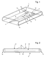
- the light guide according to the invention is shown in perspective at the figure 1 .
- this light guide is generally in the form of a closed loop on itself. It comprises a light injection zone 2 facing which a light source 4 is arranged. Any type of light source such as a filament bulb or a light-emitting diode may be used in the context of the present invention.
- the light is injected into the light guide 1 according to the invention in a substantially rectilinear direction XX.
- the zone 2 for injecting light is extended, via a first semi-cylindrical transmission zone 6, by a zone 8 for extracting light.
- This light extraction zone 8 is provided with a plurality of optical extractors 10 for extracting the light from the light guide 1 and directing it towards the surface of an information display device 12 of the type reflective such as a liquid crystal cell.
- the reflective display device 12 is slid and wrapped inside the loop formed by the light guide 1.
- the display face 14 of the information of the display device 12 is turned on the side of the zone 8 for extracting the light from the light guide 1.
- the light extraction zone 8 is itself extended by a second semi-cylindrical transmission zone 16 which is connected to the light injection zone 2.
- the light from the light source 4 which is not extracted from the light guide 1 at the extraction zone 8 for the illumination of the information display device 12 continues its way to the inside the light guide 1 and returns to its starting point at the area 2 of injection of light.
- the light which is not used at the level of the extraction zone 8 is reinjected into the light guide 1 in the same direction of propagation as the light initially injected by the light source 4 and thus optimally interacts with the light extractors 10, whereby the coupling of the light in the guide 1 is improved and most of the light recovered at the extraction zone 8 is reused.
- the lighting of the display device information 12 is homogeneous over the entire surface thereof and much brighter than with the solutions of the prior art.
- the semi-cylindrical transmission zone 16 is connected to the light injection zone 2 via two connecting sections A and B of substantially triangular shape.
- a triangular shape makes it possible to occupy a maximum surface area between the semi-cylindrical transmission zone 16 and the light injection zone 2 without modifying the parabolic profile of the injection zone 2.
- the triangular shape of the two sections connection A and B also makes it possible to maintain a certain collimation of the light so that the recycled light returns to the zone 8 for extracting the light along propagation directions that are mainly parallel to the longitudinal axis of symmetry of the guide 1.
- the optical behavior of the light guide 1 according to the invention has been studied by means of optical modeling and simulation tools. It was assumed that the light guide 1 was for example made of glass and had a constant thickness of 0.4 mm throughout its length. Of course, the light guide 1 may be made of another transparent dielectric material such as a plastic material or polymethyl methacrylate better known by its acronym PMMA. The radius of curvature of the first and second semi-cylindrical transmission zones 6 and 16 has been chosen equal to 0.95 mm.
- the simulated light source 4 corresponds to a light-emitting diode having a light emission lobe similar to that of light-emitting diodes, especially those marketed by Kingbright. It will be noted that the optical extractors 10 have not been taken into account in the present modeling insofar as the aim is to evaluate the behavior of the part of the light which precisely did not interact with these extractors.
- the above modeling has also found that the luminous flux inside the light guide 1 had good parallelism with propagation directions within a maximum angle of 20 °.
- the injection zone 2 is of parabolic shape, the light source 4 being placed opposite the top 18 of the dish.
- This configuration is such that a majority (about 80%) of the light injected by the light source 4 into the guide 1 undergoes a total reflection inside the guide 1 and can not escape from it. therefore, the reflection of the light is total at the interface between the guide 1 and the ambient air. It is therefore not necessary to resort to artifices such as a metallization of the periphery of the light guide 1 to ensure that the light does not escape the guide 1.
- the parabolic shape of the area of Injection 2 has the effect of collimating the beams of light emitted by the light source 4 in directions of propagation parallel to the axis of symmetry of the parabola which coincides with the direction of injection XX of the light in the guide 1 .
- figure 3 is a view of an alternative embodiment of the light guide 1 according to the invention.
- this is a transmissive type information display device 20.
- the light guide 22 has the same geometry as the light guide 1 illustrated in FIG. figure 2 .
- the zone 24 for extracting the light disposed in the extension of the light injection zone 26, is located beneath the surface of the display device 20, so as to illuminate it by the rear.
- the extraction zone 24 is then extended by a first semi-cylindrical transmission portion 26 itself extended by a second flat transmission portion 28 which closes on the light injection zone 26 via a third semi-transmission portion.
- the first, second and third transmission portions 26, 28 and 30 serve only to reduce the light that has not been used at the extraction zone 24 to the injection zone 26 so as to that it can be reinjected into the guide 22. It will be understood that the display surface 32 of the information display device 20 is oriented upwards, facing the flat transmission portion 28.
Landscapes
- Physics & Mathematics (AREA)
- General Physics & Mathematics (AREA)
- Optics & Photonics (AREA)
- Planar Illumination Modules (AREA)
- Devices For Indicating Variable Information By Combining Individual Elements (AREA)
- Light Guides In General And Applications Therefor (AREA)
Description
La présente invention concerne un système d'éclairage d'un dispositif d'affichage d'informations comprenant un guide de lumière. Plus précisément, la présente invention concerne un dispositif d'extraction de lumière avec système de récupération de la lumière non utilisée pour l'éclairage d'un dispositif d'affichage d'informations.The present invention relates to a lighting system of an information display device comprising a light guide. More specifically, the present invention relates to a light extraction device with an unused light recovery system for illuminating an information display device.
Un tel système est connu de
Dans ce qui suit, on s'intéresse en particulier à l'éclairage par l'avant d'un dispositif d'affichage tel qu'une cellule à cristal liquide de type réflectif. Cette technique est mieux connue sous sa dénomination anglo-saxonne d'illumination «front light».In what follows, we are particularly interested in the lighting from the front of a display device such as a reflective type liquid crystal cell. This technique is better known by its Anglo-Saxon name of illumination "front light".
Une technique connue pour assurer l'éclairage par l'avant d'un dispositif d'affichage de type réflectif consiste à disposer au-dessus du dispositif d'affichage un guide de lumière transparent à l'intérieur duquel est injectée de la lumière. Le guide de lumière est structuré de manière à permettre progressivement l'extraction de la lumière qui s'y propage en direction du dispositif d'affichage sous-jacent. Les structures prévues dans le guide de lumière pour permettre l'extraction de la lumière sont appelées «extracteurs de lumière». Le nombre, la géométrie et la distribution de ces extracteurs à l'intérieur du guide de lumière varient en fonction des applications.One known technique for providing front illumination of a reflective type of display device is to provide above the display device a transparent light guide within which is injected light. The light guide is structured so as to gradually allow the extraction of the light that propagates there in the direction of the underlying display device. The structures provided in the light guide to allow the extraction of light are called "light extractors". The number, geometry and distribution of these extractors within the light guide vary depending on the applications.
La sélection d'un type donné d'extracteur de lumière qui soit apte à fournir un bon niveau d'illumination sans toutefois dégrader le contraste d'affichage des informations fournies par le dispositif d'affichage est une tâche ardue. En effet, pour des raisons notamment esthétiques que l'on comprendra aisément, de tels extracteurs de lumière doivent en particulier être aussi peu visibles que possible au regard de l'utilisateur et pouvoir assurer un éclairage du dispositif d'affichage qui soit aussi uniforme que possible sur toute la surface du dispositif d'affichage. Cette dernière condition est tout particulièrement importante dans le cas de l'éclairage d'un dispositif d'affichage intégré dans une montre-bracelet.The selection of a given type of light extractor which is able to provide a good level of illumination without, however, degrading the display contrast of the information provided by the display device is a difficult task. Indeed, for reasons including aesthetic that we It will be readily understood that such light extractors must in particular be as little visible as possible to the user and be able to provide illumination of the display device which is as uniform as possible over the entire surface of the display device. This last condition is particularly important in the case of lighting a display device integrated in a wristwatch.
Le premier problème qui se pose dans le cas de l'éclairage par l'avant ou illumination front-light d'un dispositif d'affichage réflectif au moyen d'un guide de lumière et qui pénalise l'uniformité de l'éclairage est lié au principe même de fonctionnement d'un tel guide de lumière.The first problem in the case of front lighting or front-light illumination of a reflective display device by means of a light guide and which penalizes the uniformity of illumination is related the very principle of operation of such a light guide.
En effet, en appelant P0 la puissance optique injectée par une source lumineuse à l'entrée du guide de lumière et en supposant que ce guide possède une efficacité E d'extraction de la lumière par unité de longueur, la puissance optique interne subsistant à l'intérieur du guide de lumière en fonction de la distance z parcourue par la lumière dans le guide est donnée par la formule P0e-E.Z. Par suite, la puissance optique Pextr(z) que l'on peut extraire du guide en un point z donné de la longueur du guide est proportionnelle à la puissance optique interne selon la relation : ![]()
![]()
L'équation (1) ci-dessus montre que si l'efficacité d'extraction E de la lumière reste la même tout le long du guide de lumière, la puissance optique Pextr(z) extraite du guide décroît exponentiellement avec la distance au point d'injection de la lumière dans le guide. Par conséquent, l'éclairage du dispositif d'affichage ne sera pas uniforme sur toute la surface de celui-ci.Equation (1) above shows that if the extraction efficiency E of the light remains the same all along the light guide, the optical power P extr (z) extracted from the guide decreases exponentially with the distance to the light. point of injection of light into the guide. Therefore, the illumination of the display device will not be uniform over the entire surface thereof.
Pour remédier à ce problème, une première solution consisterait à créer un guide de lumière présentant une efficacité d'extraction de la lumière variable avec la distance au point d'injection de la lumière dans le guide. Plus précisément, l'efficacité d'extraction de la lumière du guide devrait croître au fur et à mesure que l'on s'éloigne du point d'injection de la lumière dans le guide. Une telle solution est cependant difficile à mettre en oeuvre. En effet, l'efficacité d'extraction de la lumière reste, par définition, toujours inférieure à 1. Par conséquent, l'efficacité d'extraction ne peut croître indéfiniment en fonction de l'éloignement au point d'injection de la lumière dans le guide. En outre, pour obtenir une variation continue de l'efficacité d'extraction de la lumière le long du guide, il faudrait modifier continûment la géométrie ou la profondeur des extracteurs de lumière dans le guide, ce qui requerrait des efforts considérables en termes de conception et de fabrication du guide de lumière.To remedy this problem, a first solution would be to create a light guide having a variable light extraction efficiency with the distance to the injection point of the light in the guide. Specifically, the light extraction efficiency of the guide should increase as one moves away from the injection point of the light in the guide. Such a solution is however difficult to implement. Indeed, the efficiency of light extraction remains, by definition, always less than 1. Therefore, the extraction efficiency can not grow indefinitely depending on the distance to the injection point of the light in guide. In addition, to obtain a continuous variation in light extraction efficiency along the guide, the geometry or depth of the light extractors in the guide should be continuously changed, which would require considerable design effort. and manufacturing the light guide.
Une autre solution pour compenser la décroissance exponentielle de la puissance optique extraite du guide de lumière consisterait à procurer un guide présentant une efficacité d'extraction optique constante tout le long du guide et très faible, c'est-à-dire très inférieure à 1. Dans ce cas, l'équation (1) indiquée ci-dessus pourrait s'approximer comme suit : ![]()
![]()
L'équation (2) ci-dessus montre qu'avec une efficacité d'extraction optique constante et très faible, la puissance optique extraite du guide de lumière est sensiblement la même tout le long du guide et égale à la puissance optique injectée dans le guide à l'entrée de celui-ci. En pratique, cette solution est plus facile à réaliser car elle ne nécessite pas de devoir faire varier la géométrie des extracteurs le long du guide. En effet, l'efficacité d'extraction de la lumière doit être la même tout le long du guide optique. Toutefois, cette seconde solution pose également un problème. Effectivement, pour être vérifiée, l'équation (2) ci-dessus implique que l'efficacité d'extraction de la lumière soit très faible. Autrement dit, seule une faible partie de la puissance lumineuse initialement injectée dans le guide de lumière est réellement utilisée pour éclairer le dispositif d'affichage réflectif. Quant au reste de la puissance lumineuse injectée dans le guide de lumière, il sera expulsé ou absorbé une fois parvenu au niveau de la sortie du guide et donc définitivement perdu. Par conséquent, le rendement optique d'un tel système est médiocre.Equation (2) above shows that with a constant and very low optical extraction efficiency, the optical power extracted from the light guide is substantially the same all along the guide and equal to the optical power injected into the beam. guide at the entrance of it. In practice, this solution is easier to achieve because it does not require having to vary the geometry of the extractors along the guide. Indeed, the extraction efficiency of the light must be the same all along the optical guide. However, this second solution is also a problem. Indeed, to be verified, equation (2) above implies that the efficiency of light extraction is very low. In other words, only a small portion of the light power initially injected into the light guide is actually used to illuminate the reflective display device. As for the rest of the light power injected into the light guide, it will be expelled or absorbed once at the output of the guide and thus permanently lost. As a result, the optical efficiency of such a system is poor.
Pour remédier à ce problème, on pourrait envisager de disposer un miroir à la sortie du guide de lumière de façon à réinjecter dans le guide la lumière qui s'échappe de celui-ci. Une telle solution n'est cependant pas très appropriée au genre de guide de lumière dont il est question ici. En effet, une fois réfléchie à l'intérieur du guide, la lumière se propage dans le guide selon une direction opposée à sa direction de propagation initiale et son interaction avec les extracteurs n'est plus la même car ces derniers présentent généralement une structure asymétrique qui est optimisée pour extraire la lumière provenant directement de la source disposée à l'entrée du guide. La lumière se propageant en sens opposé serait donc extraite ou diffusée de manière non optimisée et dégraderait le contraste d'affichage du dispositif d'affichage.To remedy this problem, one could consider having a mirror at the exit of the light guide so as to reinject into the guide light that escapes from it. Such a solution, however, is not very appropriate to the kind of light guide that is being discussed here. Indeed, once reflected inside the guide, the light propagates in the guide in a direction opposite to its direction of initial propagation and its interaction with the extractors is no longer the same because the latter generally have an asymmetrical structure which is optimized to extract the light coming directly from the source disposed at the entrance of the guide. Light propagating in the opposite direction would therefore be extracted or diffused in a non-optimized manner and would degrade the display contrast of the display device.
La présente invention a pour but de pallier les inconvénients susmentionnés ainsi que d'autres encore en procurant un guide de lumière présentant notamment un rendement optique amélioré.The present invention aims to overcome the aforementioned drawbacks as well as others by providing a light guide including improved optical performance.
A cet effet, la présente invention concerne un système d'éclairage d'un dispositif d'affichage d'informations selon la revendication 1 annexée à la présente demande de brevet.For this purpose, the present invention relates to a lighting system of an information display device according to claim 1 attached to the present patent application.
Le système d'éclairage d'un dispositif d'affichage d'informations comprend un guide de lumière dans lequel la lumière qui n'est pas extraite au niveau de la zone d'extraction pour l'éclairage du dispositif d'affichage d'informations poursuit son chemin à l'intérieur du guide de lumière et revient à son point de départ au niveau de la zone d'injection de la lumière. Ainsi, la lumière inutilisée au niveau de la zone d'extraction est recyclée et réinjectée dans le guide de lumière dans le même sens de propagation que la lumière initialement injectée et interagit donc de manière optimale avec les extracteurs de lumière, grâce à quoi le couplage de la lumière dans le guide est amélioré et la plus grande partie de la lumière récupérée au niveau de la zone d'extraction est réutilisée. L'éclairage du dispositif d'affichage d'informations est donc homogène sur toute la surface de celui-ci et beaucoup plus lumineux qu'avec les solutions de l'art antérieur.The illumination system of an information display device comprises a light guide in which light which is not extracted at the extraction zone for illumination of the information display device continues on its way inside the light guide and returns to its starting point at the level of the injection zone of the light. Thus, the unused light at the extraction zone is recycled and reinjected into the light guide in the same direction of propagation as the initially injected light and thus optimally interacts with the light extractors, whereby the coupling light in the guide is improved and most of the light recovered at the extraction zone is reused. The illumination of the information display device is homogeneous over the entire surface thereof and much brighter than with the solutions of the prior art.
Un autre avantage de l'invention réside dans le fait que dans le cas où le dispositif d'affichage d'informations est de type réflectif, ce dispositif d'affichage d'informations est éclairé par le dessus, c'est-à-dire du côté où sont affichées les informations, tandis que la source de lumière est disposée sous le dispositif d'affichage. On obtient ainsi un système d'éclairage très compact dans lequel le dispositif d'affichage d'informations est enveloppé dans le guide de lumière. Par ailleurs, la source lumineuse étant disposée sous le dispositif d'éclairage, le halo produit par la source lumineuse, phénomène encore connu sous sa dénomination "hot spot" en terminologie anglo-saxonne, n'est pas perceptible par l'utilisateur.Another advantage of the invention lies in the fact that in the case where the information display device is of reflective type, this information display device is illuminated from above, that is to say on the side where the information is displayed, while the light source is disposed under the display. A very compact lighting system is thus obtained in which the information display device is wrapped in the light guide. Moreover, the light source being disposed under the lighting device, the halo produced by the light source, a phenomenon also known under the name "hot spot" in English terminology, is not perceptible by the user.
Inversement, dans le cas où le dispositif d'affichage d'informations est de type transmissif, ce dispositif d'affichage, enveloppé dans le guide de lumière, sera éclairé par le dessous. Dans ce cas aussi, le système d'éclairage résultant est très compact. On observe par ailleurs le grand degré de polyvalence du système d'éclairage selon l'invention qui, moyennant quelques modifications mineures, est capable d'éclairer de manière homogène et intense aussi bien un dispositif d'affichage réflectif qu'un dispositif d'affichage transmissif.Conversely, in the case where the information display device is transmissive type, this display device, wrapped in the light guide, will be illuminated from below. In this case too, the resulting lighting system is very compact. Furthermore, the great degree of versatility of the lighting system according to the invention is observed, which, with a few minor modifications, is capable of uniformly and intensively illuminating both a reflective display device and a display device. transmissive.
D'autres caractéristiques et avantages de la présente invention ressortiront plus clairement à la lecture de la description détaillée qui suit d'un mode de réalisation du système d'éclairage selon l'invention, cet exemple étant donné à titre purement illustratif et non limitatif seulement en liaison avec le dessin annexé sur lequel :
- la
figure 1 est une vue en perspective d'un guide de lumière conforme à la présente invention ; - la
figure 2 est une vue en coupe du système d'éclairage complet selon l'invention avec introduction d'un dispositif d'affichage d'informations de type réflectif à l'intérieur de la boucle formée par le guide de lumière, et - la
figure 3 est une vue analogue à celle de lafigure 2 , le dispositif d'affichage d'informations étant de type transmissif.
- the
figure 1 is a perspective view of a light guide according to the present invention; - the
figure 2 is a sectional view of the complete lighting system according to the invention with introduction of a reflective type information display device inside the loop formed by the light guide, and - the
figure 3 is a view similar to that of thefigure 2 , the information display device being of transmissive type.
Le guide de lumière décrit dans la présente demande de brevet présente une forme en boucle et permet de la sorte de ramener au niveau de la zone d'injection lumineuse du guide de lumière la lumière qui n'a pas été extraite du guide au niveau d'une zone d'extraction. A cet effet, le guide de lumière comprend une zone d'injection de la lumière prolongée par une zone d'extraction de la lumière qui se referme sur la zone d'injection. Ainsi, la lumière non-utilisée au niveau de la zone d'extraction du guide est réinjectée dans la zone d'injection elle-même prolongée par une zone de transmission qui ramène la lumière non-utilisée au niveau de la zone d'extraction. La lumière réinjectée dans le guide de lumière se propage donc dans la même direction que la lumière injectée initialement, de sorte que l'efficacité des extracteurs dans la zone d'extraction vis-à-vis de la lumière réinjectée est identique à l'efficacité de ces mêmes extracteurs vis-à-vis de la lumière initialement injectée par la source lumineuse. L'illumination du dispositif d'affichage d'informations est homogène sur toute la surface de celui-ci et est plus intense. Grâce à ces caractéristiques, le dispositif d'affichage d'informations, enveloppé dans le guide de lumière, peut, moyennant quelques modifications mineures, être indifféremment éclairé par le dessus s'il est de type réflectif ou par le dessous s'il est de type transmissif. En outre, l'invention procure un système d'éclairage très compact.The light guide described in the present patent application has a looped shape and allows in this way to bring back to the level of the light injection zone of the light guide light that has not been extracted from the guide at the level of the light. an extraction zone. For this purpose, the light guide comprises a light injection zone extended by a light extraction zone which closes on the injection zone. Thus, the unused light at the extraction zone of the guide is reinjected into the injection zone itself prolonged by a transmission zone which brings the unused light to the level of the extraction zone. The light re-injected into the light guide therefore propagates in the same direction as the light initially injected, so that the efficiency of the extractors in the extraction zone vis-à-vis the reinjected light is identical to the efficiency of these same extractors vis-à-vis the light initially injected by the light source. The illumination of the information display device is homogeneous over the entire surface thereof and is more intense. Thanks to these characteristics, the information display device, wrapped in the light guide, can, with some minor modifications, be indifferently illuminated from above if it is of the reflective type or from below if it is from transmissive type. In addition, the invention provides a very compact lighting system.
La présente invention va être décrite en liaison avec un dispositif d'affichage d'informations de type réflectif, c'est-à-dire nécessitant une illumination par le dessus encore appelée «front lighting» en terminologie anglo-saxonne. Plus précisément, la présente invention va être décrite en liaison avec un dispositif d'affichage à cristal liquide de type réflectif. Il va néanmoins de soi que la présente invention s'applique de manière similaire à un dispositif d'affichage d'informations de type transmissif.The present invention will be described in connection with a reflective type information display device, that is to say requiring an illumination from above also called "front lighting" in English terminology. More specifically, the present invention will be described in connection with a reflective type liquid crystal display device. It goes without saying, however, that the present invention applies similarly to a transmissive type information display device.
Le guide de lumière selon l'invention est représenté en perspective à la
La zone 2 d'injection de la lumière est prolongée, via une première zone de transmission semi-cylindrique 6, par une zone 8 d'extraction de la lumière. Cette zone 8 d'extraction de la lumière est pourvue d'une pluralité d'extracteurs optiques 10 destinés à extraire la lumière du guide de lumière 1 et à la diriger vers la surface d'un dispositif d'affichage d'informations 12 de type réflectif tel qu'une cellule à cristal liquide. Comme on peut le voir sur la
La zone 8 d'extraction de la lumière est elle-même prolongée par une seconde zone de transmission semi-cylindrique 16 qui se raccorde à la zone 2 d'injection de la lumière. Ainsi, la lumière provenant de la source lumineuse 4 et qui n'est pas extraite du guide de lumière 1 au niveau de la zone d'extraction 8 pour l'éclairage du dispositif d'affichage d'informations 12 poursuit son chemin à l'intérieur du guide de lumière 1 et revient à son point de départ au niveau de la zone 2 d'injection de la lumière. On comprendra que la lumière qui n'est pas utilisée au niveau de la zone d'extraction 8 est réinjectée dans le guide de lumière 1 dans le même sens de propagation que la lumière initialement injectée par la source lumineuse 4 et interagit donc de manière optimale avec les extracteurs de lumière 10, grâce à quoi le couplage de la lumière dans le guide 1 est amélioré et la plus grande partie de la lumière récupérée au niveau de la zone d'extraction 8 est réutilisée. L'éclairage du dispositif d'affichage d'informations 12 est donc homogène sur toute la surface de celui-ci et beaucoup plus lumineux qu'avec les solutions de l'art antérieur.The
On remarquera que la zone de transmission semi-cylindrique 16 se raccorde à la zone 2 d'injection de la lumière via deux sections de raccordement A et B de forme sensiblement triangulaire. Une telle forme triangulaire permet d'occuper un maximum de surface entre la zone de transmission semi-cylindrique 16 et la zone 2 d'injection de la lumière sans modification du profil parabolique de la zone d'injection 2. La forme triangulaire des deux sections de raccordement A et B permet également de conserver une certaine collimation de la lumière afin que la lumière recyclée revienne dans la zone 8 d'extraction de la lumière suivant des directions de propagation majoritairement parallèles à l'axe de symétrie longitudinale du guide 1.It will be noted that the
Le comportement optique du guide de lumière 1 selon l'invention a été étudié au moyen d'outils de modélisation et de simulation optiques. On a supposé que le guide de lumière 1 était par exemple réalisé en verre et présentait une épaisseur constante de 0,4 mm sur toute sa longueur. Bien entendu, le guide de lumière 1 peut être réalisé en un autre matériau diélectrique transparent tel qu'un matériau plastique ou bien du polyméthyl méthacrylate mieux connu sous son acronyme PMMA. Le rayon de courbure des première et seconde zones de transmission semi-cylindriques 6 et 16 a été choisi égal à 0,95 mm. La source de lumière 4 simulée correspond à une diode électroluminescente présentant un lobe d'émission lumineuse semblable à celui des diodes électroluminescentes notamment commercialisées par la société Kingbright. On notera que les extracteurs optiques 10 n'ont pas été pris en compte dans la présente modélisation dans la mesure où le but recherché est d'évaluer le comportement de la partie de la lumière qui justement n'a pas interagi avec ces extracteurs.The optical behavior of the light guide 1 according to the invention has been studied by means of optical modeling and simulation tools. It was assumed that the light guide 1 was for example made of glass and had a constant thickness of 0.4 mm throughout its length. Of course, the light guide 1 may be made of another transparent dielectric material such as a plastic material or polymethyl methacrylate better known by its acronym PMMA. The radius of curvature of the first and second
La modélisation du guide de lumière 1 décrite ci-dessus conduit aux résultats suivants :
- couplage de la lumière dans le guide de lumière 1 supérieur à 70% de la puissance lumineuse initialement fournie par
la diode électroluminescente 4 ; - jusqu'à 76% de la lumière qui traverse
la zone d'extraction 8 sans être extraite du guide de lumière 1 est récupérée au niveau de lazone d'injection 2 et est réutilisée.
- coupling light in the light guide 1 greater than 70% of the light power initially supplied by the light-emitting
diode 4; - up to 76% of the light passing through the
extraction zone 8 without being extracted from the light guide 1 is recovered at theinjection zone 2 and is reused.
La modélisation ci-dessus a également permis de constater que le flux lumineux à l'intérieur du guide de lumière 1 présentait un bon parallélisme avec des directions de propagation comprises dans un angle maximal de 20°. En effet, comme cela est visible à la
Il va de soi que la présente invention n'est pas limitée aux modes de réalisation qui viennent d'être décrits et que diverses modifications et variantes simples peuvent être envisagées par l'homme du métier sans sortir du cadre de l'invention tel que défini par les revendications annexées à la présente demande de brevet. En particulier, la
Claims (5)
- Lighting system for a data display device (12, 20), wherein said lighting system includes a light guide (1; 22) including an area (2; 26) into which the light produced by at least one light source (4) is injected, the light guide further comprising an area (8; 24) for extracting the light propagating inside the guide (1; 22) to light the display device (12; 20), said extraction area (8; 24) coming in the extension of the injection area being provided with light extractors (10), wherein the light guide (1; 22) takes the form of a loop closed on itself at the light injection area (2; 26) to allow the light originating from the light source (4) and which was not extracted from the light guide (1; 22) in the extraction area (8; 24) to continue to travel inside the light guide (1; 22) and to return to the starting point thereof at the light injection area (2; 26), characterized in that the light guide (1; 22) is dimensioned so that data display device (12; 20) can be arranged inside the loop, and in that the light extractors (10) are arranged so as:(a) to direct the extracted light towards the data display surface (14) of the data display device (12) when the latter is of the reflective type and its data display surface (14) is turned towards the extraction zone (8), or(b) to direct the extracted light towards the rear surface of the data display device (20) opposed to its data display surface (32) when the latter is of the transmissive type and its rear surface is turned towards the extraction zone (24).
- Lighting system according to claim 1, characterized in that the light injection area (2) is extended, via a first semi-cylindrical transmission area (6), by the light extraction area (8), wherein said light extraction area (8) is extended in turn by a second semi-cylindrical transmission area (16), which is connected to the light injection area (2), the data display device (1) is of the reflective type with the data display surface (14) oriented towards the light extraction area (8) of the light guide (1).
- Lighting system according to claim 1, characterized in that the light extraction area (24), arranged in the extension of the light injection area (26), is extended by a first semi-cylindrical transmission portion (26), which is in turn extended by a second flat transmission portion (28), which is closed on the light injection area (26) via a third semi-cylindrical transmission portion (30), the first, second and third transmission portions (26, 28, 30) being used solely for returning the light that has not been used in the extraction area (24) to the injection area (26) for re-injection into the guide (22), and the data display device (20) being of the transmissive type with the data display surface (32) thereof oriented towards the flat transmission portion (28).
- Lighting system according to any of claims 2 or 3, characterized in that the second semi-cylindrical transmission portion (16) and the third semi-cylindrical transmission portion (30) are connected to the light injection area (2) by two, substantially triangular connector sections (A, B).
- Lighting system according to any of claims 1 to 4, characterized in that the light injection area (2; 26) has a parabolic profile.
Priority Applications (6)
| Application Number | Priority Date | Filing Date | Title |
|---|---|---|---|
| EP10164825A EP2392952B1 (en) | 2010-06-03 | 2010-06-03 | Lighting system for an information display device including a light guide |
| JP2011117732A JP5244215B2 (en) | 2010-06-03 | 2011-05-26 | Lighting systems for data display devices including light guides |
| US13/151,052 US8517589B2 (en) | 2010-06-03 | 2011-06-01 | Lighting system for a data display device including a light guide |
| CN201110147552.1A CN102313201B (en) | 2010-06-03 | 2011-06-02 | Lighting system for an information display device including a light guide |
| KR1020110053155A KR101190474B1 (en) | 2010-06-03 | 2011-06-02 | Lighting system for a data display device including a light guide |
| HK12105473.1A HK1164977A1 (en) | 2010-06-03 | 2012-06-05 | Lighting system for a data display device including a light guide |
Applications Claiming Priority (1)
| Application Number | Priority Date | Filing Date | Title |
|---|---|---|---|
| EP10164825A EP2392952B1 (en) | 2010-06-03 | 2010-06-03 | Lighting system for an information display device including a light guide |
Publications (2)
| Publication Number | Publication Date |
|---|---|
| EP2392952A1 EP2392952A1 (en) | 2011-12-07 |
| EP2392952B1 true EP2392952B1 (en) | 2012-12-12 |
Family
ID=42947393
Family Applications (1)
| Application Number | Title | Priority Date | Filing Date |
|---|---|---|---|
| EP10164825A Active EP2392952B1 (en) | 2010-06-03 | 2010-06-03 | Lighting system for an information display device including a light guide |
Country Status (6)
| Country | Link |
|---|---|
| US (1) | US8517589B2 (en) |
| EP (1) | EP2392952B1 (en) |
| JP (1) | JP5244215B2 (en) |
| KR (1) | KR101190474B1 (en) |
| CN (1) | CN102313201B (en) |
| HK (1) | HK1164977A1 (en) |
Families Citing this family (2)
| Publication number | Priority date | Publication date | Assignee | Title |
|---|---|---|---|---|
| TWI554866B (en) * | 2015-10-06 | 2016-10-21 | 宇帷國際股份有限公司 | Electronic device |
| TWI602049B (en) * | 2015-10-06 | 2017-10-11 | 英信科技有限公司 | Electronic Device |
Family Cites Families (8)
| Publication number | Priority date | Publication date | Assignee | Title |
|---|---|---|---|---|
| JPH09325336A (en) * | 1996-06-03 | 1997-12-16 | Keiji Iimura | Surface type light source device and passive type display device with same |
| GB2324599A (en) | 1997-04-22 | 1998-10-28 | Ford Motor Co | Looped light pipe illuminator for illuminating dials etc. |
| JP2001318235A (en) * | 2000-05-10 | 2001-11-16 | Bridgestone Corp | Liquid crystal illuminator |
| JP2003031016A (en) * | 2001-07-10 | 2003-01-31 | Minolta Co Ltd | Planar lighting device and image display device |
| US6874924B1 (en) * | 2002-03-14 | 2005-04-05 | Ilight Technologies, Inc. | Illumination device for simulation of neon lighting |
| JP2009503793A (en) * | 2005-07-28 | 2009-01-29 | ライト プレスクリプションズ イノベーターズ エルエルシー | Etendue-conserving illumination optics for backlights and frontlights |
| JP2009265960A (en) * | 2008-04-25 | 2009-11-12 | Panasonic Corp | Traffic signal |
| WO2009134573A1 (en) * | 2008-04-30 | 2009-11-05 | 3M Innovative Properties Company | Light injection coupler and lighting system including the same |
-
2010
- 2010-06-03 EP EP10164825A patent/EP2392952B1/en active Active
-
2011
- 2011-05-26 JP JP2011117732A patent/JP5244215B2/en active Active
- 2011-06-01 US US13/151,052 patent/US8517589B2/en active Active
- 2011-06-02 KR KR1020110053155A patent/KR101190474B1/en not_active IP Right Cessation
- 2011-06-02 CN CN201110147552.1A patent/CN102313201B/en active Active
-
2012
- 2012-06-05 HK HK12105473.1A patent/HK1164977A1/en unknown
Also Published As
| Publication number | Publication date |
|---|---|
| US8517589B2 (en) | 2013-08-27 |
| CN102313201B (en) | 2014-07-09 |
| HK1164977A1 (en) | 2012-09-28 |
| CN102313201A (en) | 2012-01-11 |
| US20110299300A1 (en) | 2011-12-08 |
| EP2392952A1 (en) | 2011-12-07 |
| JP2011253810A (en) | 2011-12-15 |
| KR101190474B1 (en) | 2012-10-12 |
| JP5244215B2 (en) | 2013-07-24 |
| KR20110132994A (en) | 2011-12-09 |
Similar Documents
| Publication | Publication Date | Title |
|---|---|---|
| EP2791717B1 (en) | Optical guide with superposed guidance elements and method of manufacture | |
| EP2341375B1 (en) | Device for collimation, homogenisation and extraction of light for lighting a display device | |
| EP2541291B1 (en) | Light guide with decoupling portion and cover collecting the decoupled rays | |
| EP2891007B1 (en) | Optical device comprising an optical waveguide and method for manufacturing such a device | |
| CH696516A5 (en) | Portable instrument for measuring a physiological quantity comprising a device for illuminating the surface of an organic tissue. | |
| EP1867913B1 (en) | Lighting or signalling device with an optical guide for an automobile vehicle | |
| EP0017922B1 (en) | Diffusing surface structure for a light guide in an information display device | |
| FR2970543A1 (en) | OPTICALLY GUIDED LIGHTING OR SIGNALING DEVICE FOR MOTOR VEHICLE | |
| FR3012624A1 (en) | OPTICAL GUIDE ADAPTED TO CREATE TWO LIGHT FINGERPRINTS | |
| FR2782829A1 (en) | LUMINOUS DISPLAY PANELS | |
| EP1801492A1 (en) | Lighting or signalling device with an optical guide for an automobile | |
| EP1826607A1 (en) | Liquid crystal display device displaying coloured segments and timepiece equipped with such a device | |
| EP2392952B1 (en) | Lighting system for an information display device including a light guide | |
| EP3428739B1 (en) | Display assembly | |
| EP1479338B1 (en) | Portable instrument for measuring a physiological variable comprising a device to illuminate the surface of organic tissue | |
| CH703287A2 (en) | Lighting system for transmissive type information display device used in wrist watch, has light guide in loop form that closes guide to allow light which is not extracted from guide to continue its path and to return to starting point | |
| FR3048067A1 (en) | SUPERIOR OPTICAL GUIDES PRODUCING DIFFERENT LUMINOUS PATTERNS | |
| EP0499536B1 (en) | Illuminated pointer | |
| EP3315857B1 (en) | Improved angled light guide | |
| WO2016030217A1 (en) | Light-emitting diode lighting device comprising a light compatible with the use of night vision binoculars and comprising a light guide | |
| EP2896878B1 (en) | Light guide for a lighting and/or signalling device | |
| CH702435A2 (en) | System for lighting reflective information display device of i.e. watch, has light extraction zone provided with light extractors, and light guide provided with plane light injection and collimation zone in form of parabola | |
| WO2013139721A1 (en) | System for injecting light into a waveguide, waveguide device and assembly for injecting light into a waveguide | |
| WO2013010689A1 (en) | Light guide for illuminating a display device | |
| CH713977B1 (en) | Display assembly, in particular for a timepiece. |
Legal Events
| Date | Code | Title | Description |
|---|---|---|---|
| AK | Designated contracting states |
Kind code of ref document: A1 Designated state(s): AL AT BE BG CH CY CZ DE DK EE ES FI FR GB GR HR HU IE IS IT LI LT LU LV MC MK MT NL NO PL PT RO SE SI SK SM TR |
|
| AX | Request for extension of the european patent |
Extension state: BA ME RS |
|
| PUAI | Public reference made under article 153(3) epc to a published international application that has entered the european phase |
Free format text: ORIGINAL CODE: 0009012 |
|
| 17P | Request for examination filed |
Effective date: 20120608 |
|
| 17Q | First examination report despatched |
Effective date: 20120711 |
|
| GRAP | Despatch of communication of intention to grant a patent |
Free format text: ORIGINAL CODE: EPIDOSNIGR1 |
|
| GRAS | Grant fee paid |
Free format text: ORIGINAL CODE: EPIDOSNIGR3 |
|
| GRAA | (expected) grant |
Free format text: ORIGINAL CODE: 0009210 |
|
| AK | Designated contracting states |
Kind code of ref document: B1 Designated state(s): AL AT BE BG CH CY CZ DE DK EE ES FI FR GB GR HR HU IE IS IT LI LT LU LV MC MK MT NL NO PL PT RO SE SI SK SM TR |
|
| REG | Reference to a national code |
Ref country code: GB Ref legal event code: FG4D Free format text: NOT ENGLISH |
|
| REG | Reference to a national code |
Ref country code: CH Ref legal event code: EP |
|
| REG | Reference to a national code |
Ref country code: AT Ref legal event code: REF Ref document number: 588565 Country of ref document: AT Kind code of ref document: T Effective date: 20121215 |
|
| REG | Reference to a national code |
Ref country code: CH Ref legal event code: NV Representative=s name: ICB INGENIEURS CONSEILS EN BREVETS SA, CH |
|
| REG | Reference to a national code |
Ref country code: IE Ref legal event code: FG4D Free format text: LANGUAGE OF EP DOCUMENT: FRENCH |
|
| REG | Reference to a national code |
Ref country code: DE Ref legal event code: R096 Ref document number: 602010004053 Country of ref document: DE Effective date: 20130207 |
|
| PG25 | Lapsed in a contracting state [announced via postgrant information from national office to epo] |
Ref country code: FI Free format text: LAPSE BECAUSE OF FAILURE TO SUBMIT A TRANSLATION OF THE DESCRIPTION OR TO PAY THE FEE WITHIN THE PRESCRIBED TIME-LIMIT Effective date: 20121212 Ref country code: LT Free format text: LAPSE BECAUSE OF FAILURE TO SUBMIT A TRANSLATION OF THE DESCRIPTION OR TO PAY THE FEE WITHIN THE PRESCRIBED TIME-LIMIT Effective date: 20121212 Ref country code: ES Free format text: LAPSE BECAUSE OF FAILURE TO SUBMIT A TRANSLATION OF THE DESCRIPTION OR TO PAY THE FEE WITHIN THE PRESCRIBED TIME-LIMIT Effective date: 20130323 Ref country code: SE Free format text: LAPSE BECAUSE OF FAILURE TO SUBMIT A TRANSLATION OF THE DESCRIPTION OR TO PAY THE FEE WITHIN THE PRESCRIBED TIME-LIMIT Effective date: 20121212 Ref country code: NO Free format text: LAPSE BECAUSE OF FAILURE TO SUBMIT A TRANSLATION OF THE DESCRIPTION OR TO PAY THE FEE WITHIN THE PRESCRIBED TIME-LIMIT Effective date: 20130312 Ref country code: HR Free format text: LAPSE BECAUSE OF FAILURE TO SUBMIT A TRANSLATION OF THE DESCRIPTION OR TO PAY THE FEE WITHIN THE PRESCRIBED TIME-LIMIT Effective date: 20121212 |
|
| REG | Reference to a national code |
Ref country code: NL Ref legal event code: VDEP Effective date: 20121212 |
|
| REG | Reference to a national code |
Ref country code: AT Ref legal event code: MK05 Ref document number: 588565 Country of ref document: AT Kind code of ref document: T Effective date: 20121212 |
|
| REG | Reference to a national code |
Ref country code: LT Ref legal event code: MG4D |
|
| PG25 | Lapsed in a contracting state [announced via postgrant information from national office to epo] |
Ref country code: GR Free format text: LAPSE BECAUSE OF FAILURE TO SUBMIT A TRANSLATION OF THE DESCRIPTION OR TO PAY THE FEE WITHIN THE PRESCRIBED TIME-LIMIT Effective date: 20130313 Ref country code: LV Free format text: LAPSE BECAUSE OF FAILURE TO SUBMIT A TRANSLATION OF THE DESCRIPTION OR TO PAY THE FEE WITHIN THE PRESCRIBED TIME-LIMIT Effective date: 20121212 Ref country code: SI Free format text: LAPSE BECAUSE OF FAILURE TO SUBMIT A TRANSLATION OF THE DESCRIPTION OR TO PAY THE FEE WITHIN THE PRESCRIBED TIME-LIMIT Effective date: 20121212 |
|
| PG25 | Lapsed in a contracting state [announced via postgrant information from national office to epo] |
Ref country code: AT Free format text: LAPSE BECAUSE OF FAILURE TO SUBMIT A TRANSLATION OF THE DESCRIPTION OR TO PAY THE FEE WITHIN THE PRESCRIBED TIME-LIMIT Effective date: 20121212 Ref country code: BG Free format text: LAPSE BECAUSE OF FAILURE TO SUBMIT A TRANSLATION OF THE DESCRIPTION OR TO PAY THE FEE WITHIN THE PRESCRIBED TIME-LIMIT Effective date: 20130312 Ref country code: EE Free format text: LAPSE BECAUSE OF FAILURE TO SUBMIT A TRANSLATION OF THE DESCRIPTION OR TO PAY THE FEE WITHIN THE PRESCRIBED TIME-LIMIT Effective date: 20121212 Ref country code: IS Free format text: LAPSE BECAUSE OF FAILURE TO SUBMIT A TRANSLATION OF THE DESCRIPTION OR TO PAY THE FEE WITHIN THE PRESCRIBED TIME-LIMIT Effective date: 20130412 Ref country code: SK Free format text: LAPSE BECAUSE OF FAILURE TO SUBMIT A TRANSLATION OF THE DESCRIPTION OR TO PAY THE FEE WITHIN THE PRESCRIBED TIME-LIMIT Effective date: 20121212 Ref country code: CZ Free format text: LAPSE BECAUSE OF FAILURE TO SUBMIT A TRANSLATION OF THE DESCRIPTION OR TO PAY THE FEE WITHIN THE PRESCRIBED TIME-LIMIT Effective date: 20121212 |
|
| PG25 | Lapsed in a contracting state [announced via postgrant information from national office to epo] |
Ref country code: PT Free format text: LAPSE BECAUSE OF FAILURE TO SUBMIT A TRANSLATION OF THE DESCRIPTION OR TO PAY THE FEE WITHIN THE PRESCRIBED TIME-LIMIT Effective date: 20130412 Ref country code: NL Free format text: LAPSE BECAUSE OF FAILURE TO SUBMIT A TRANSLATION OF THE DESCRIPTION OR TO PAY THE FEE WITHIN THE PRESCRIBED TIME-LIMIT Effective date: 20121212 Ref country code: PL Free format text: LAPSE BECAUSE OF FAILURE TO SUBMIT A TRANSLATION OF THE DESCRIPTION OR TO PAY THE FEE WITHIN THE PRESCRIBED TIME-LIMIT Effective date: 20121212 Ref country code: RO Free format text: LAPSE BECAUSE OF FAILURE TO SUBMIT A TRANSLATION OF THE DESCRIPTION OR TO PAY THE FEE WITHIN THE PRESCRIBED TIME-LIMIT Effective date: 20121212 |
|
| PLBE | No opposition filed within time limit |
Free format text: ORIGINAL CODE: 0009261 |
|
| STAA | Information on the status of an ep patent application or granted ep patent |
Free format text: STATUS: NO OPPOSITION FILED WITHIN TIME LIMIT |
|
| PG25 | Lapsed in a contracting state [announced via postgrant information from national office to epo] |
Ref country code: DK Free format text: LAPSE BECAUSE OF FAILURE TO SUBMIT A TRANSLATION OF THE DESCRIPTION OR TO PAY THE FEE WITHIN THE PRESCRIBED TIME-LIMIT Effective date: 20121212 |
|
| 26N | No opposition filed |
Effective date: 20130913 |
|
| PG25 | Lapsed in a contracting state [announced via postgrant information from national office to epo] |
Ref country code: CY Free format text: LAPSE BECAUSE OF FAILURE TO SUBMIT A TRANSLATION OF THE DESCRIPTION OR TO PAY THE FEE WITHIN THE PRESCRIBED TIME-LIMIT Effective date: 20121212 |
|
| BERE | Be: lapsed |
Owner name: THE SWATCH GROUP RESEARCH AND DEVELOPMENT LTD. Effective date: 20130630 |
|
| PG25 | Lapsed in a contracting state [announced via postgrant information from national office to epo] |
Ref country code: IT Free format text: LAPSE BECAUSE OF FAILURE TO SUBMIT A TRANSLATION OF THE DESCRIPTION OR TO PAY THE FEE WITHIN THE PRESCRIBED TIME-LIMIT Effective date: 20121212 |
|
| REG | Reference to a national code |
Ref country code: DE Ref legal event code: R097 Ref document number: 602010004053 Country of ref document: DE Effective date: 20130913 |
|
| PG25 | Lapsed in a contracting state [announced via postgrant information from national office to epo] |
Ref country code: MC Free format text: LAPSE BECAUSE OF FAILURE TO SUBMIT A TRANSLATION OF THE DESCRIPTION OR TO PAY THE FEE WITHIN THE PRESCRIBED TIME-LIMIT Effective date: 20121212 |
|
| REG | Reference to a national code |
Ref country code: IE Ref legal event code: MM4A |
|
| PG25 | Lapsed in a contracting state [announced via postgrant information from national office to epo] |
Ref country code: BE Free format text: LAPSE BECAUSE OF NON-PAYMENT OF DUE FEES Effective date: 20130630 |
|
| PG25 | Lapsed in a contracting state [announced via postgrant information from national office to epo] |
Ref country code: IE Free format text: LAPSE BECAUSE OF NON-PAYMENT OF DUE FEES Effective date: 20130603 |
|
| GBPC | Gb: european patent ceased through non-payment of renewal fee |
Effective date: 20140603 |
|
| PG25 | Lapsed in a contracting state [announced via postgrant information from national office to epo] |
Ref country code: MT Free format text: LAPSE BECAUSE OF FAILURE TO SUBMIT A TRANSLATION OF THE DESCRIPTION OR TO PAY THE FEE WITHIN THE PRESCRIBED TIME-LIMIT Effective date: 20121212 |
|
| PG25 | Lapsed in a contracting state [announced via postgrant information from national office to epo] |
Ref country code: SM Free format text: LAPSE BECAUSE OF FAILURE TO SUBMIT A TRANSLATION OF THE DESCRIPTION OR TO PAY THE FEE WITHIN THE PRESCRIBED TIME-LIMIT Effective date: 20121212 Ref country code: GB Free format text: LAPSE BECAUSE OF NON-PAYMENT OF DUE FEES Effective date: 20140603 |
|
| PG25 | Lapsed in a contracting state [announced via postgrant information from national office to epo] |
Ref country code: TR Free format text: LAPSE BECAUSE OF FAILURE TO SUBMIT A TRANSLATION OF THE DESCRIPTION OR TO PAY THE FEE WITHIN THE PRESCRIBED TIME-LIMIT Effective date: 20121212 |
|
| PG25 | Lapsed in a contracting state [announced via postgrant information from national office to epo] |
Ref country code: MK Free format text: LAPSE BECAUSE OF FAILURE TO SUBMIT A TRANSLATION OF THE DESCRIPTION OR TO PAY THE FEE WITHIN THE PRESCRIBED TIME-LIMIT Effective date: 20121212 Ref country code: LU Free format text: LAPSE BECAUSE OF NON-PAYMENT OF DUE FEES Effective date: 20130603 Ref country code: HU Free format text: LAPSE BECAUSE OF FAILURE TO SUBMIT A TRANSLATION OF THE DESCRIPTION OR TO PAY THE FEE WITHIN THE PRESCRIBED TIME-LIMIT; INVALID AB INITIO Effective date: 20100603 |
|
| REG | Reference to a national code |
Ref country code: FR Ref legal event code: PLFP Year of fee payment: 7 |
|
| REG | Reference to a national code |
Ref country code: FR Ref legal event code: PLFP Year of fee payment: 8 |
|
| REG | Reference to a national code |
Ref country code: FR Ref legal event code: PLFP Year of fee payment: 9 |
|
| PG25 | Lapsed in a contracting state [announced via postgrant information from national office to epo] |
Ref country code: AL Free format text: LAPSE BECAUSE OF FAILURE TO SUBMIT A TRANSLATION OF THE DESCRIPTION OR TO PAY THE FEE WITHIN THE PRESCRIBED TIME-LIMIT Effective date: 20121212 |
|
| P01 | Opt-out of the competence of the unified patent court (upc) registered |
Effective date: 20230615 |
|
| PGFP | Annual fee paid to national office [announced via postgrant information from national office to epo] |
Ref country code: FR Payment date: 20230523 Year of fee payment: 14 Ref country code: DE Payment date: 20230523 Year of fee payment: 14 |
|
| PGFP | Annual fee paid to national office [announced via postgrant information from national office to epo] |
Ref country code: CH Payment date: 20230702 Year of fee payment: 14 |