EP2390980A1 - Method and device for detecting an intermittent earth fault in a multiple feeder system - Google Patents
Method and device for detecting an intermittent earth fault in a multiple feeder system Download PDFInfo
- Publication number
- EP2390980A1 EP2390980A1 EP10164502A EP10164502A EP2390980A1 EP 2390980 A1 EP2390980 A1 EP 2390980A1 EP 10164502 A EP10164502 A EP 10164502A EP 10164502 A EP10164502 A EP 10164502A EP 2390980 A1 EP2390980 A1 EP 2390980A1
- Authority
- EP
- European Patent Office
- Prior art keywords
- earth
- feeding loop
- feeding
- earth fault
- correlation
- Prior art date
- Legal status (The legal status is an assumption and is not a legal conclusion. Google has not performed a legal analysis and makes no representation as to the accuracy of the status listed.)
- Granted
Links
Images


Classifications
-
- H—ELECTRICITY
- H02—GENERATION; CONVERSION OR DISTRIBUTION OF ELECTRIC POWER
- H02H—EMERGENCY PROTECTIVE CIRCUIT ARRANGEMENTS
- H02H1/00—Details of emergency protective circuit arrangements
- H02H1/0007—Details of emergency protective circuit arrangements concerning the detecting means
- H02H1/0015—Using arc detectors
-
- H—ELECTRICITY
- H02—GENERATION; CONVERSION OR DISTRIBUTION OF ELECTRIC POWER
- H02H—EMERGENCY PROTECTIVE CIRCUIT ARRANGEMENTS
- H02H7/00—Emergency protective circuit arrangements specially adapted for specific types of electric machines or apparatus or for sectionalised protection of cable or line systems, and effecting automatic switching in the event of an undesired change from normal working conditions
- H02H7/26—Sectionalised protection of cable or line systems, e.g. for disconnecting a section on which a short-circuit, earth fault, or arc discharge has occured
- H02H7/267—Sectionalised protection of cable or line systems, e.g. for disconnecting a section on which a short-circuit, earth fault, or arc discharge has occured for parallel lines and wires
-
- H—ELECTRICITY
- H02—GENERATION; CONVERSION OR DISTRIBUTION OF ELECTRIC POWER
- H02H—EMERGENCY PROTECTIVE CIRCUIT ARRANGEMENTS
- H02H9/00—Emergency protective circuit arrangements for limiting excess current or voltage without disconnection
- H02H9/08—Limitation or suppression of earth fault currents, e.g. Petersen coil
Definitions
- the present disclosure relates to a method and a corresponding monitoring device for detecting earth faults in a power distribution system, wherein a busbar feeds power to a plurality of feeding loops, wherein a distribution grid feeds power to the busbar via a transformer, the secondary side of which is connected to earth via a Petersen coil, and wherein the Petersen coil voltage and the feeding loop currents are measured to provide an earth fault indication.
- One object of the present disclosure is therefore to provide a more reliable detecting method and a monitoring device capable of carrying out that method. This object is achieved by means of a method as defined in claim 1 and a corresponding monitoring device as defined in claim 7.
- the initially mentioned method then involves providing the first order derivative of the Peterson coil voltage, correlating this first order derivative with each feeding loop current, and indicating the feeding loop with the highest correlation as having an earth fault.
- flank information may be such that an incorrect decision is made due to different impedances in the system. This does however not affect the presently disclosed method, which carries out a correlation over time. Despite this, a determination may be made based on one single intermittent fault.
- the indicating may include comparing the correlation results with a first, positive threshold, and indicating the feeding loop exceeding the first threshold as exhibiting an earth fault.
- the correlation results may be integrated for a period of time and the feeding loop with the highest integrated correlation is indicated as exhibiting an earth fault.
- the Petersen coil voltage signal may be high-pass filtered to remove the grid frequency, or the differentiated signal may be set to zero unless it exceeds a second threshold.
- the indication may be triggered by the differentiated signal exceeding a third threshold.
- the present disclosure further relates to a monitoring device devised to carry out the above-indicated method.
- the monitoring device includes functional blocks that are adapted to carry out the actions of the method.
- Fig 1 illustrates a power distribution system where the detecting method and the monitoring device of the present disclosure may be used.
- a high voltage grid 1 in the illustrated case e.g. 132kV, is connected via a power transformer 3, to a medium voltage distribution system 5, which in the illustrated case runs with a 20kV voltage.
- the medium voltage distribution system 5 has a busbar 7, with a number of, usually open, feeding loops 9, 11, 13, 15, 17, 19. Each feeding loop typically has a plurality of substation power transformers (not shown) connected thereto, providing for instance 400V power to resident buildings, offices, etc.
- the secondary side of the power transformer which has a Y configuration, is connected to earth via a Petersen coil 21, as is well known per se. There is thus provided a non-effectively grounded substation.
- the feeding loops may often comprise buried, insulated cables.
- the buried cables may include both three-phase cables, having a common enclosure, and sets of three individual single-phase cables.
- One problem associated with such buried cables is earth faults, which occur when the insulation becomes deteriorated due to ageing and/or damage. Often, the insulation may have imperfections which may cause a short-circuit between one phase of the cable and earth.
- a plurality of temporary earth faults with very short durations typically 0.5-2 ms
- intermittent or re-striking earth faults occur over a number of days or weeks before the short circuit becomes permanent and the feeding loop must be disconnected. Since the temporary earth faults are so short in duration, the breaker (not shown) of the feeding loop with the fault does not usually disconnect the feeding loop.
- the grid operator can undertake necessary measures before the cable breaks down permanently. Thereby the breakdown can be prevented or the damage caused by the breakdown can be minimized.
- the object of the method to be disclosed is to decide which feeding loop exhibits an intermittent earth fault among all the feeding loops fed by the transformer.
- the inventor of the present disclosure has found that there is a great correlation between, on the one hand, the first order derivatives of the voltage over the Petersen coil 21 and, on the other hand, the current of the feeder cable exhibiting an intermittent fault. Therefore a very basic method, which may be altered and expanded in different ways as will be described later, can be summarized as follows with regard to the flow chart illustrated in fig 2 .
- the method includes the following actions. Although those actions are shown in a particular order, it is evident that some of the actions can have a reversed order or may be carried out simultaneously.
- the method thus includes measuring 25 the Petersen coil voltage, i.e. the neutral point voltage of the busbar. Further, the feeding loop currents are measured 27. This implies the measuring of each cable's zero current, i.e. in a three phase system, the vector sum of the current of each phase.
- the first order derivative or differential of the neutral point voltage is provided 29, and is correlated 31 with each of the monitored feeding loop zero currents. Based on these correlations, it is indicated 33 which one of the feeding loops that exhibited an earth fault. In general, the faulty loop will over time exhibit a positive correlation with the neutral point voltage derivative, while the non-faulty loops will have a negative correlation.
- Fig 3 illustrates schematically the layout of a monitoring device 35.
- the monitoring device may be accomplished by means of a digital signal processor running a software, by means of a field programmable gate array, FPGA, or even as a truly analog arrangement, by means of operational amplifiers.
- FPGA field programmable gate array
- an FGPA is considered a preferred solution, but as mentioned other realizations are within the reach of the skilled person.
- the monitoring device will comprise a number of functional blocks carrying out the actions indicated in fig 2 .
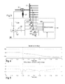
- Fig 4 shows a graph of a neutral voltage during a time frame of 1 ms where an intermittent earth fault occurs. It should be noted that an intermittent fault often occurs when the voltage of the damaged phase is close to its peak.
- the total time frame illustrated in fig 4 and the following graphs is one tenth of a 50 Hz half period.
- Fig 5 shows the first order derivative of the neutral voltage during the time frame in question.
- the information in the measured signal that is useful for finding the damaged feeder resides to a great extent in the transient caused by the intermittent earth fault that will mainly comprise high frequency components as compared to the grid frequency. It may therefore be preferred to exclude low frequencies, such as any influence from the 50 Hz grid frequency from the analysis. This may be done by means of an optional low pass filter 39, filtering the neutral voltage. Another option is to provide a threshold block 41, which sets all derivative readings with amplitudes smaller than a predetermined threshold to zero, i.e. effectively disregarding slow (non-transient) changes in the neutral voltage. This will also filter out any effects of the grid frequency components as well as its harmonic components (mainly odd multiples of the grid frequency).
- Fig 6 shows the currents of a set of feeder cables, denoted F2, F3, F12, and F15 during the time frame of figs 4 and 5 .
- the currents are the zero currents of each of those cables.
- correlation blocks 43-53 By means of a number of correlation blocks 43-53, the correlations between the Petersen coil voltage's first order derivative and each of the monitored cables' currents are determined.
- a correlation is here meant a sample-wise multiplication of the differentiated voltage with the current. The resulting product may in principle be standardized even if this is not necessary.
- Fig 7 illustrates the correlation of each of the cable currents of fig 6 with the first order derivative of the neutral voltage of fig 5 . Those correlations are fed to a determination block 55.
- the determination block 55 of fig 3 can thus determine which cable is about to break down by comparing the received correlation with a positive threshold at one or a few instants (consecutive or non-consecutive).
- FIG 8 shows the integrals of each of the signals depicted in fig 7 , integrated over the entire duration of an intermittent fault transient. There it is clearly shown that the feeder cable F2 has the greatest correlation over time and was the cable that caused the intermittent earth fault.
- the determination block 55 timing can be determined by the output from the differentiating unit 37, as illustrated in fig 3 . This means that the correlations can be compared with the threshold when the differentiated signal exceeds another threshold or that the same condition can cause an integrating operation to commence.
- the present disclosure relates to a method and a corresponding monitoring device for detecting earth faults in a power distribution system, where a busbar feeds power to a plurality of feeding loops, and a distribution grid feeds power to the busbar via a transformer.
- the secondary side of the transformer is connected to earth via a Petersen coil.
- the Petersen coil voltage and the feeding loop currents are measured, and the first order derivative of the Peterson coil voltage is determined.
- This derivative is correlated with each of the feeding loop currents, and the feeding loop with the highest correlation over a predetermined time is detected as having an earth fault.
Landscapes
- Testing Of Short-Circuits, Discontinuities, Leakage, Or Incorrect Line Connections (AREA)
Abstract
Description
- The present disclosure relates to a method and a corresponding monitoring device for detecting earth faults in a power distribution system, wherein a busbar feeds power to a plurality of feeding loops, wherein a distribution grid feeds power to the busbar via a transformer, the secondary side of which is connected to earth via a Petersen coil, and wherein the Petersen coil voltage and the feeding loop currents are measured to provide an earth fault indication.
- Such a method is described e.g. in
EP 1526621 , where the flanks of the feeding loop currents and the Peterson coil voltage are compared in the moment when the intermittent fault occurs. It is correctly assumed that the polarity of the flank in the faulty cable's current will differ from all the other currents, and that cable may be detected has exhibiting an earth fault accordingly. - One problem associated with such a scheme is that it is not always reliable.
- One object of the present disclosure is therefore to provide a more reliable detecting method and a monitoring device capable of carrying out that method. This object is achieved by means of a method as defined in
claim 1 and a corresponding monitoring device as defined in claim 7. - More specifically, the initially mentioned method then involves providing the first order derivative of the Peterson coil voltage, correlating this first order derivative with each feeding loop current, and indicating the feeding loop with the highest correlation as having an earth fault.
- This provides a more reliable detection, as the method is relieved from actually finding the flanks with information that is sufficient for making the correct determination. It is to be noted that, temporarily during a transient, the flank information may be such that an incorrect decision is made due to different impedances in the system. This does however not affect the presently disclosed method, which carries out a correlation over time. Despite this, a determination may be made based on one single intermittent fault.
- The indicating may include comparing the correlation results with a first, positive threshold, and indicating the feeding loop exceeding the first threshold as exhibiting an earth fault.
- Alternatively, the correlation results may be integrated for a period of time and the feeding loop with the highest integrated correlation is indicated as exhibiting an earth fault.
- The Petersen coil voltage signal may be high-pass filtered to remove the grid frequency, or the differentiated signal may be set to zero unless it exceeds a second threshold.
- The indication may be triggered by the differentiated signal exceeding a third threshold.
- The present disclosure further relates to a monitoring device devised to carry out the above-indicated method. In general, the monitoring device includes functional blocks that are adapted to carry out the actions of the method.
-
-
Fig 1 schematically illustrates a power distribution system. -
Fig 2 shows a flow chart for a method according to the present disclosure. -
Fig 3 illustrates schematically the layout of a monitoring device. -
Fig 4 shows a graph of a neutral voltage during a time frame of 1 ms where an intermittent earth fault occurs. -
Fig 5 shows the first order derivative of the neutral voltage during the time frame. -
Fig 6 shows the currents of a set of feeder cables during the time frame. -
Fig 7 shows the correlation of the each of the cable currents offig 6 with the first order derivative of the neutral voltage offig 5 . -
Fig 8 shows the integrals of each of the signals depicted infig 7 . -
Fig 1 illustrates a power distribution system where the detecting method and the monitoring device of the present disclosure may be used. Ahigh voltage grid 1, in the illustrated case e.g. 132kV, is connected via a power transformer 3, to a medium voltage distribution system 5, which in the illustrated case runs with a 20kV voltage. The medium voltage distribution system 5 has a busbar 7, with a number of, usually open,feeding loops - The secondary side of the power transformer, which has a Y configuration, is connected to earth via a Petersen
coil 21, as is well known per se. There is thus provided a non-effectively grounded substation. - The feeding loops may often comprise buried, insulated cables. In three-phase systems, the buried cables may include both three-phase cables, having a common enclosure, and sets of three individual single-phase cables. One problem associated with such buried cables is earth faults, which occur when the insulation becomes deteriorated due to ageing and/or damage. Often, the insulation may have imperfections which may cause a short-circuit between one phase of the cable and earth. Usually, in such cases, a plurality of temporary earth faults with very short durations (typically 0.5-2 ms), sometimes called intermittent or re-striking earth faults, occur over a number of days or weeks before the short circuit becomes permanent and the feeding loop must be disconnected. Since the temporary earth faults are so short in duration, the breaker (not shown) of the feeding loop with the fault does not usually disconnect the feeding loop.
- Thus, if the preceding earth faults with short duration can be detected, the grid operator can undertake necessary measures before the cable breaks down permanently. Thereby the breakdown can be prevented or the damage caused by the breakdown can be minimized.
- In the following there will be described a simple but yet reliable monitoring device that is able of detecting intermittent earth faults, such that a power system operator can undertake different actions so as to minimize the damage caused by the malfunctioning cable.
- The object of the method to be disclosed is to decide which feeding loop exhibits an intermittent earth fault among all the feeding loops fed by the transformer.
- The inventor of the present disclosure has found that there is a great correlation between, on the one hand, the first order derivatives of the voltage over the Petersen
coil 21 and, on the other hand, the current of the feeder cable exhibiting an intermittent fault. Therefore a very basic method, which may be altered and expanded in different ways as will be described later, can be summarized as follows with regard to the flow chart illustrated infig 2 . - Briefly, the method includes the following actions. Although those actions are shown in a particular order, it is evident that some of the actions can have a reversed order or may be carried out simultaneously.
- The method thus includes measuring 25 the Petersen coil voltage, i.e. the neutral point voltage of the busbar. Further, the feeding loop currents are measured 27. This implies the measuring of each cable's zero current, i.e. in a three phase system, the vector sum of the current of each phase.
- The first order derivative or differential of the neutral point voltage is provided 29, and is correlated 31 with each of the monitored feeding loop zero currents. Based on these correlations, it is indicated 33 which one of the feeding loops that exhibited an earth fault. In general, the faulty loop will over time exhibit a positive correlation with the neutral point voltage derivative, while the non-faulty loops will have a negative correlation.
-
Fig 3 illustrates schematically the layout of amonitoring device 35. In general the monitoring device may be accomplished by means of a digital signal processor running a software, by means of a field programmable gate array, FPGA, or even as a truly analog arrangement, by means of operational amplifiers. In general, an FGPA is considered a preferred solution, but as mentioned other realizations are within the reach of the skilled person. In any case, the monitoring device will comprise a number of functional blocks carrying out the actions indicated infig 2 . - The voltage over the Petersen coil is sampled and measured, as is well known per se, and its first order derivative is accomplished by a differentiating unit or
block 37.Fig 4 shows a graph of a neutral voltage during a time frame of 1 ms where an intermittent earth fault occurs. It should be noted that an intermittent fault often occurs when the voltage of the damaged phase is close to its peak. The total time frame illustrated infig 4 and the following graphs is one tenth of a 50 Hz half period.Fig 5 shows the first order derivative of the neutral voltage during the time frame in question. - The information in the measured signal that is useful for finding the damaged feeder resides to a great extent in the transient caused by the intermittent earth fault that will mainly comprise high frequency components as compared to the grid frequency. It may therefore be preferred to exclude low frequencies, such as any influence from the 50 Hz grid frequency from the analysis. This may be done by means of an optional low pass filter 39, filtering the neutral voltage. Another option is to provide a threshold block 41, which sets all derivative readings with amplitudes smaller than a predetermined threshold to zero, i.e. effectively disregarding slow (non-transient) changes in the neutral voltage. This will also filter out any effects of the grid frequency components as well as its harmonic components (mainly odd multiples of the grid frequency).
-
Fig 6 shows the currents of a set of feeder cables, denoted F2, F3, F12, and F15 during the time frame offigs 4 and 5 . The currents are the zero currents of each of those cables. - By means of a number of correlation blocks 43-53, the correlations between the Petersen coil voltage's first order derivative and each of the monitored cables' currents are determined. By a correlation is here meant a sample-wise multiplication of the differentiated voltage with the current. The resulting product may in principle be standardized even if this is not necessary.
-
Fig 7 illustrates the correlation of each of the cable currents offig 6 with the first order derivative of the neutral voltage offig 5 . Those correlations are fed to a determination block 55. - As can be seen in
fig 7 , which shows the correlations for the different feeder cables, the correlation of the faulty cable (F2) is highly positive, whereas the correlations for all the other cables are negative. This is due to the facts that all currents are to be considered capacitive for the short duration of the intermittent fault. - The determination block 55 of
fig 3 can thus determine which cable is about to break down by comparing the received correlation with a positive threshold at one or a few instants (consecutive or non-consecutive). - A further measure to increase the reliability of the monitoring device is to integrate the received correlation over a period of time. This makes the determination even clearer.
Fig 8 shows the integrals of each of the signals depicted infig 7 , integrated over the entire duration of an intermittent fault transient. There it is clearly shown that the feeder cable F2 has the greatest correlation over time and was the cable that caused the intermittent earth fault. - The determination block 55 timing can be determined by the output from the differentiating
unit 37, as illustrated infig 3 . This means that the correlations can be compared with the threshold when the differentiated signal exceeds another threshold or that the same condition can cause an integrating operation to commence. - In summary, the present disclosure relates to a method and a corresponding monitoring device for detecting earth faults in a power distribution system, where a busbar feeds power to a plurality of feeding loops, and a distribution grid feeds power to the busbar via a transformer. The secondary side of the transformer is connected to earth via a Petersen coil. The Petersen coil voltage and the feeding loop currents are measured, and the first order derivative of the Peterson coil voltage is determined. This derivative is correlated with each of the feeding loop currents, and the feeding loop with the highest correlation over a predetermined time is detected as having an earth fault. This provides a simple but yet reliable scheme for detecting an intermittent earth fault, such that measures can be taken to replace a damaged cable before it breaks down permanently.
- The invention is not restricted to the described embodiment. It may be varied and altered in different ways within the scope of the appended claims.
Claims (7)
- A method for detecting earth faults in a power distribution system, wherein a busbar feeds power to a plurality of feeding loops, wherein a distribution grid feeds power to the busbar via a transformer, the secondary side of which is connected to earth via a Petersen coil (21), and wherein the Petersen coil voltage and the feeding loop currents are measured (25, 27) to provide an earth fault indication, characterised by- providing (29) the first order derivative of the Peterson coil voltage as a differential signal,- correlating (31) the differential signal with the feeding loop currents to provide correlation results, and- indicating (33) the feeding loop with the highest positive correlation as having an earth fault.
- A method as claimed in claim 1, wherein the indicating includes comparing the correlation results with a first, positive threshold, and indicating the feeding loop exceeding the first threshold as exhibiting an earth fault.
- A method as claimed in claim 1 or 2, wherein the correlation results are integrated for a period of time and the feeding loop with the highest integrated correlation is indicated as exhibiting an earth fault.
- A method according to any of the preceding claims, wherein the Petersen coil voltage signal is high-pass filtered to remove the grid frequency.
- A method according to any of the preceding claims, wherein the differentiated signal is set to zero unless it exceeds a second threshold.
- A method according to any of the preceding claims, wherein the indication is triggered by the differentiated signal exceeding a third threshold.
- A monitoring device for detecting earth faults in a power distribution system, wherein a busbar feeds power to a plurality of feeding loops, wherein a distribution grid feeds power to the busbar via a transformer, the secondary side of which is connected to earth via a Petersen coil, and wherein the Petersen coil voltage and the feeding loop currents are measured to provide an earth fault indication, the device characterised by- a differential unit (37) for providing the first order derivative of the Peterson coil voltage,- correlation units (43-53) for correlating the first order derivative with the feeding loop currents, and- a determination unit (55) indicating the feeding loop with the highest positive correlation as having an earth fault.
Priority Applications (1)
| Application Number | Priority Date | Filing Date | Title |
|---|---|---|---|
| EP20100164502 EP2390980B1 (en) | 2010-05-31 | 2010-05-31 | Method and device for detecting an intermittent earth fault in a multiple feeder system |
Applications Claiming Priority (1)
| Application Number | Priority Date | Filing Date | Title |
|---|---|---|---|
| EP20100164502 EP2390980B1 (en) | 2010-05-31 | 2010-05-31 | Method and device for detecting an intermittent earth fault in a multiple feeder system |
Publications (2)
| Publication Number | Publication Date |
|---|---|
| EP2390980A1 true EP2390980A1 (en) | 2011-11-30 |
| EP2390980B1 EP2390980B1 (en) | 2013-01-02 |
Family
ID=42797551
Family Applications (1)
| Application Number | Title | Priority Date | Filing Date |
|---|---|---|---|
| EP20100164502 Active EP2390980B1 (en) | 2010-05-31 | 2010-05-31 | Method and device for detecting an intermittent earth fault in a multiple feeder system |
Country Status (1)
| Country | Link |
|---|---|
| EP (1) | EP2390980B1 (en) |
Cited By (2)
| Publication number | Priority date | Publication date | Assignee | Title |
|---|---|---|---|---|
| US9217775B2 (en) | 2010-06-07 | 2015-12-22 | Abb Research Ltd. | Systems and methods for characterizing fault clearing devices |
| US9692258B2 (en) | 2013-12-06 | 2017-06-27 | Abb Research Ltd. | Method and system for multi-IED event classification in an electrical grid |
Citations (4)
| Publication number | Priority date | Publication date | Assignee | Title |
|---|---|---|---|---|
| WO2002015358A1 (en) * | 2000-08-11 | 2002-02-21 | Adaptive Regelsysteme Gesellschaft M.B.H. | Method and device for localising single-pole earth faults |
| DE10302451B3 (en) * | 2003-01-22 | 2004-07-15 | Edc Gmbh | Earthing connection recognition method for 3-phase network using evaluation of charge curve obtained by integration of current from voltage zero transition and zero voltage limit value point |
| EP1526621A1 (en) | 2003-10-22 | 2005-04-27 | Trench Austria GmbH | Method for identifying intermittent ground faults |
| DE60120698T2 (en) * | 2000-06-13 | 2007-03-29 | Electricité de France Service National | METHOD FOR DETECTING RESISTANT ERRORS |
-
2010
- 2010-05-31 EP EP20100164502 patent/EP2390980B1/en active Active
Patent Citations (4)
| Publication number | Priority date | Publication date | Assignee | Title |
|---|---|---|---|---|
| DE60120698T2 (en) * | 2000-06-13 | 2007-03-29 | Electricité de France Service National | METHOD FOR DETECTING RESISTANT ERRORS |
| WO2002015358A1 (en) * | 2000-08-11 | 2002-02-21 | Adaptive Regelsysteme Gesellschaft M.B.H. | Method and device for localising single-pole earth faults |
| DE10302451B3 (en) * | 2003-01-22 | 2004-07-15 | Edc Gmbh | Earthing connection recognition method for 3-phase network using evaluation of charge curve obtained by integration of current from voltage zero transition and zero voltage limit value point |
| EP1526621A1 (en) | 2003-10-22 | 2005-04-27 | Trench Austria GmbH | Method for identifying intermittent ground faults |
Cited By (4)
| Publication number | Priority date | Publication date | Assignee | Title |
|---|---|---|---|---|
| US9217775B2 (en) | 2010-06-07 | 2015-12-22 | Abb Research Ltd. | Systems and methods for characterizing fault clearing devices |
| US10324132B2 (en) | 2010-06-07 | 2019-06-18 | Abb Inc. | Systems and methods for power line event zone identification |
| US10422833B2 (en) | 2010-06-07 | 2019-09-24 | Abb Research Ltd. | Systems and methods for classifying power line events |
| US9692258B2 (en) | 2013-12-06 | 2017-06-27 | Abb Research Ltd. | Method and system for multi-IED event classification in an electrical grid |
Also Published As
| Publication number | Publication date |
|---|---|
| EP2390980B1 (en) | 2013-01-02 |
Similar Documents
| Publication | Publication Date | Title |
|---|---|---|
| Bo et al. | Accurate fault location technique for distribution system using fault-generated high-frequency transient voltage signals | |
| CN101943737B (en) | Single-phase earth fault diagnosis method and device | |
| FI115488B (en) | Method and apparatus for detecting a breaking earth fault in a power distribution network | |
| EP2741389B1 (en) | Ground fault direction determination for medium or high voltage distribution networks | |
| US7865321B2 (en) | Arcing event detection | |
| RU2557017C2 (en) | Fault identification and directional detection in three-phase power system | |
| EP2506408A2 (en) | Ground scheme identification method | |
| KR20120036804A (en) | Method and system for transient and intermittent earth fault detection and direction determination in a three phase median voltage electric power distribution system | |
| JP2013539336A (en) | Detection system, detection method and self-test method | |
| EP3299828B1 (en) | Electrical fault detection | |
| CN102420420A (en) | Single-phase grounding protection method and system | |
| EP2887082A1 (en) | Improved noise propagation immunity of a multi-string arc fault detection device | |
| CN104515934A (en) | HHT (Hilbert-Huang transform)-based microcomputer small-current earth-fault line selection device | |
| KR20100049216A (en) | Method for detecting arc in power distribution system and system for alerting arc using the same method | |
| KR101490770B1 (en) | Ground fault detecting apparatus | |
| EP2390980B1 (en) | Method and device for detecting an intermittent earth fault in a multiple feeder system | |
| JP2019507344A (en) | Apparatus and associated method for determining a ground fault | |
| EP3499252B1 (en) | Single-phase-to-ground fault detection method and device based on monitoring of changes of electric field intensities | |
| CN112383030A (en) | Novel arc light protection method and device for switch cabinet | |
| JP5529300B1 (en) | High voltage insulation monitoring method and high voltage insulation monitoring device | |
| CN106199346B (en) | Device for monitoring partial discharges in an electrical network | |
| Chen et al. | Arcing current features extraction using wavelet transform | |
| US8228103B2 (en) | Circuit breaker | |
| Renforth et al. | A novel solution for the reliable online partial discharge monitoring (OLPD) of VSD-operated Ex/ATEX HV motors | |
| KR100206661B1 (en) | Thunder waveform automatic test method and apparatus for transmission line |
Legal Events
| Date | Code | Title | Description |
|---|---|---|---|
| AK | Designated contracting states |
Kind code of ref document: A1 Designated state(s): AL AT BE BG CH CY CZ DE DK EE ES FI FR GB GR HR HU IE IS IT LI LT LU LV MC MK MT NL NO PL PT RO SE SI SK SM TR |
|
| AX | Request for extension of the european patent |
Extension state: BA ME RS |
|
| PUAI | Public reference made under article 153(3) epc to a published international application that has entered the european phase |
Free format text: ORIGINAL CODE: 0009012 |
|
| 17P | Request for examination filed |
Effective date: 20120529 |
|
| GRAP | Despatch of communication of intention to grant a patent |
Free format text: ORIGINAL CODE: EPIDOSNIGR1 |
|
| RIC1 | Information provided on ipc code assigned before grant |
Ipc: H02H 7/26 20060101ALN20120628BHEP Ipc: H02H 9/08 20060101ALN20120628BHEP Ipc: H02H 1/00 20060101AFI20120628BHEP |
|
| RAP1 | Party data changed (applicant data changed or rights of an application transferred) |
Owner name: NETCONTROL OY |
|
| GRAS | Grant fee paid |
Free format text: ORIGINAL CODE: EPIDOSNIGR3 |
|
| GRAA | (expected) grant |
Free format text: ORIGINAL CODE: 0009210 |
|
| AK | Designated contracting states |
Kind code of ref document: B1 Designated state(s): AL AT BE BG CH CY CZ DE DK EE ES FI FR GB GR HR HU IE IS IT LI LT LU LV MC MK MT NL NO PL PT RO SE SI SK SM TR |
|
| REG | Reference to a national code |
Ref country code: GB Ref legal event code: FG4D Ref country code: SE Ref legal event code: TRGR |
|
| REG | Reference to a national code |
Ref country code: CH Ref legal event code: EP Ref country code: AT Ref legal event code: REF Ref document number: 592058 Country of ref document: AT Kind code of ref document: T Effective date: 20130115 |
|
| REG | Reference to a national code |
Ref country code: IE Ref legal event code: FG4D |
|
| REG | Reference to a national code |
Ref country code: DE Ref legal event code: R096 Ref document number: 602010004383 Country of ref document: DE Effective date: 20130307 |
|
| REG | Reference to a national code |
Ref country code: AT Ref legal event code: MK05 Ref document number: 592058 Country of ref document: AT Kind code of ref document: T Effective date: 20130102 |
|
| REG | Reference to a national code |
Ref country code: NL Ref legal event code: VDEP Effective date: 20130102 |
|
| PG25 | Lapsed in a contracting state [announced via postgrant information from national office to epo] |
Ref country code: SI Free format text: LAPSE BECAUSE OF FAILURE TO SUBMIT A TRANSLATION OF THE DESCRIPTION OR TO PAY THE FEE WITHIN THE PRESCRIBED TIME-LIMIT Effective date: 20130102 |
|
| REG | Reference to a national code |
Ref country code: LT Ref legal event code: MG4D |
|
| PG25 | Lapsed in a contracting state [announced via postgrant information from national office to epo] |
Ref country code: LT Free format text: LAPSE BECAUSE OF FAILURE TO SUBMIT A TRANSLATION OF THE DESCRIPTION OR TO PAY THE FEE WITHIN THE PRESCRIBED TIME-LIMIT Effective date: 20130102 Ref country code: ES Free format text: LAPSE BECAUSE OF FAILURE TO SUBMIT A TRANSLATION OF THE DESCRIPTION OR TO PAY THE FEE WITHIN THE PRESCRIBED TIME-LIMIT Effective date: 20130413 Ref country code: BG Free format text: LAPSE BECAUSE OF FAILURE TO SUBMIT A TRANSLATION OF THE DESCRIPTION OR TO PAY THE FEE WITHIN THE PRESCRIBED TIME-LIMIT Effective date: 20130402 Ref country code: CZ Free format text: LAPSE BECAUSE OF FAILURE TO SUBMIT A TRANSLATION OF THE DESCRIPTION OR TO PAY THE FEE WITHIN THE PRESCRIBED TIME-LIMIT Effective date: 20130102 Ref country code: AT Free format text: LAPSE BECAUSE OF FAILURE TO SUBMIT A TRANSLATION OF THE DESCRIPTION OR TO PAY THE FEE WITHIN THE PRESCRIBED TIME-LIMIT Effective date: 20130102 Ref country code: BE Free format text: LAPSE BECAUSE OF FAILURE TO SUBMIT A TRANSLATION OF THE DESCRIPTION OR TO PAY THE FEE WITHIN THE PRESCRIBED TIME-LIMIT Effective date: 20130102 Ref country code: NO Free format text: LAPSE BECAUSE OF FAILURE TO SUBMIT A TRANSLATION OF THE DESCRIPTION OR TO PAY THE FEE WITHIN THE PRESCRIBED TIME-LIMIT Effective date: 20130402 Ref country code: IS Free format text: LAPSE BECAUSE OF FAILURE TO SUBMIT A TRANSLATION OF THE DESCRIPTION OR TO PAY THE FEE WITHIN THE PRESCRIBED TIME-LIMIT Effective date: 20130502 |
|
| PG25 | Lapsed in a contracting state [announced via postgrant information from national office to epo] |
Ref country code: FI Free format text: LAPSE BECAUSE OF FAILURE TO SUBMIT A TRANSLATION OF THE DESCRIPTION OR TO PAY THE FEE WITHIN THE PRESCRIBED TIME-LIMIT Effective date: 20130102 Ref country code: NL Free format text: LAPSE BECAUSE OF FAILURE TO SUBMIT A TRANSLATION OF THE DESCRIPTION OR TO PAY THE FEE WITHIN THE PRESCRIBED TIME-LIMIT Effective date: 20130102 Ref country code: PL Free format text: LAPSE BECAUSE OF FAILURE TO SUBMIT A TRANSLATION OF THE DESCRIPTION OR TO PAY THE FEE WITHIN THE PRESCRIBED TIME-LIMIT Effective date: 20130102 Ref country code: GR Free format text: LAPSE BECAUSE OF FAILURE TO SUBMIT A TRANSLATION OF THE DESCRIPTION OR TO PAY THE FEE WITHIN THE PRESCRIBED TIME-LIMIT Effective date: 20130403 Ref country code: PT Free format text: LAPSE BECAUSE OF FAILURE TO SUBMIT A TRANSLATION OF THE DESCRIPTION OR TO PAY THE FEE WITHIN THE PRESCRIBED TIME-LIMIT Effective date: 20130502 Ref country code: LV Free format text: LAPSE BECAUSE OF FAILURE TO SUBMIT A TRANSLATION OF THE DESCRIPTION OR TO PAY THE FEE WITHIN THE PRESCRIBED TIME-LIMIT Effective date: 20130102 |
|
| PG25 | Lapsed in a contracting state [announced via postgrant information from national office to epo] |
Ref country code: HR Free format text: LAPSE BECAUSE OF FAILURE TO SUBMIT A TRANSLATION OF THE DESCRIPTION OR TO PAY THE FEE WITHIN THE PRESCRIBED TIME-LIMIT Effective date: 20130102 |
|
| PG25 | Lapsed in a contracting state [announced via postgrant information from national office to epo] |
Ref country code: SK Free format text: LAPSE BECAUSE OF FAILURE TO SUBMIT A TRANSLATION OF THE DESCRIPTION OR TO PAY THE FEE WITHIN THE PRESCRIBED TIME-LIMIT Effective date: 20130102 Ref country code: DK Free format text: LAPSE BECAUSE OF FAILURE TO SUBMIT A TRANSLATION OF THE DESCRIPTION OR TO PAY THE FEE WITHIN THE PRESCRIBED TIME-LIMIT Effective date: 20130102 Ref country code: RO Free format text: LAPSE BECAUSE OF FAILURE TO SUBMIT A TRANSLATION OF THE DESCRIPTION OR TO PAY THE FEE WITHIN THE PRESCRIBED TIME-LIMIT Effective date: 20130102 Ref country code: EE Free format text: LAPSE BECAUSE OF FAILURE TO SUBMIT A TRANSLATION OF THE DESCRIPTION OR TO PAY THE FEE WITHIN THE PRESCRIBED TIME-LIMIT Effective date: 20130102 |
|
| PLBE | No opposition filed within time limit |
Free format text: ORIGINAL CODE: 0009261 |
|
| STAA | Information on the status of an ep patent application or granted ep patent |
Free format text: STATUS: NO OPPOSITION FILED WITHIN TIME LIMIT |
|
| PG25 | Lapsed in a contracting state [announced via postgrant information from national office to epo] |
Ref country code: CY Free format text: LAPSE BECAUSE OF FAILURE TO SUBMIT A TRANSLATION OF THE DESCRIPTION OR TO PAY THE FEE WITHIN THE PRESCRIBED TIME-LIMIT Effective date: 20130102 |
|
| REG | Reference to a national code |
Ref country code: DE Ref legal event code: R119 Ref document number: 602010004383 Country of ref document: DE |
|
| 26N | No opposition filed |
Effective date: 20131003 |
|
| PG25 | Lapsed in a contracting state [announced via postgrant information from national office to epo] |
Ref country code: MC Free format text: LAPSE BECAUSE OF FAILURE TO SUBMIT A TRANSLATION OF THE DESCRIPTION OR TO PAY THE FEE WITHIN THE PRESCRIBED TIME-LIMIT Effective date: 20130102 Ref country code: IT Free format text: LAPSE BECAUSE OF FAILURE TO SUBMIT A TRANSLATION OF THE DESCRIPTION OR TO PAY THE FEE WITHIN THE PRESCRIBED TIME-LIMIT Effective date: 20130102 |
|
| REG | Reference to a national code |
Ref country code: DE Ref legal event code: R097 Ref document number: 602010004383 Country of ref document: DE Effective date: 20131003 |
|
| PG25 | Lapsed in a contracting state [announced via postgrant information from national office to epo] |
Ref country code: DE Free format text: LAPSE BECAUSE OF NON-PAYMENT OF DUE FEES Effective date: 20131203 |
|
| REG | Reference to a national code |
Ref country code: DE Ref legal event code: R119 Ref document number: 602010004383 Country of ref document: DE Effective date: 20131203 |
|
| REG | Reference to a national code |
Ref country code: IE Ref legal event code: MM4A |
|
| REG | Reference to a national code |
Ref country code: FR Ref legal event code: ST Effective date: 20140131 |
|
| PG25 | Lapsed in a contracting state [announced via postgrant information from national office to epo] |
Ref country code: IE Free format text: LAPSE BECAUSE OF NON-PAYMENT OF DUE FEES Effective date: 20130531 |
|
| PG25 | Lapsed in a contracting state [announced via postgrant information from national office to epo] |
Ref country code: FR Free format text: LAPSE BECAUSE OF NON-PAYMENT OF DUE FEES Effective date: 20130531 |
|
| REG | Reference to a national code |
Ref country code: CH Ref legal event code: PL |
|
| GBPC | Gb: european patent ceased through non-payment of renewal fee |
Effective date: 20140531 |
|
| PG25 | Lapsed in a contracting state [announced via postgrant information from national office to epo] |
Ref country code: CH Free format text: LAPSE BECAUSE OF NON-PAYMENT OF DUE FEES Effective date: 20140531 Ref country code: LI Free format text: LAPSE BECAUSE OF NON-PAYMENT OF DUE FEES Effective date: 20140531 |
|
| PG25 | Lapsed in a contracting state [announced via postgrant information from national office to epo] |
Ref country code: MT Free format text: LAPSE BECAUSE OF FAILURE TO SUBMIT A TRANSLATION OF THE DESCRIPTION OR TO PAY THE FEE WITHIN THE PRESCRIBED TIME-LIMIT Effective date: 20130102 |
|
| PG25 | Lapsed in a contracting state [announced via postgrant information from national office to epo] |
Ref country code: SM Free format text: LAPSE BECAUSE OF FAILURE TO SUBMIT A TRANSLATION OF THE DESCRIPTION OR TO PAY THE FEE WITHIN THE PRESCRIBED TIME-LIMIT Effective date: 20130102 Ref country code: GB Free format text: LAPSE BECAUSE OF NON-PAYMENT OF DUE FEES Effective date: 20140531 |
|
| PG25 | Lapsed in a contracting state [announced via postgrant information from national office to epo] |
Ref country code: TR Free format text: LAPSE BECAUSE OF FAILURE TO SUBMIT A TRANSLATION OF THE DESCRIPTION OR TO PAY THE FEE WITHIN THE PRESCRIBED TIME-LIMIT Effective date: 20130102 |
|
| PG25 | Lapsed in a contracting state [announced via postgrant information from national office to epo] |
Ref country code: MK Free format text: LAPSE BECAUSE OF FAILURE TO SUBMIT A TRANSLATION OF THE DESCRIPTION OR TO PAY THE FEE WITHIN THE PRESCRIBED TIME-LIMIT Effective date: 20130102 Ref country code: LU Free format text: LAPSE BECAUSE OF NON-PAYMENT OF DUE FEES Effective date: 20130531 Ref country code: HU Free format text: LAPSE BECAUSE OF FAILURE TO SUBMIT A TRANSLATION OF THE DESCRIPTION OR TO PAY THE FEE WITHIN THE PRESCRIBED TIME-LIMIT; INVALID AB INITIO Effective date: 20100531 |
|
| PG25 | Lapsed in a contracting state [announced via postgrant information from national office to epo] |
Ref country code: AL Free format text: LAPSE BECAUSE OF FAILURE TO SUBMIT A TRANSLATION OF THE DESCRIPTION OR TO PAY THE FEE WITHIN THE PRESCRIBED TIME-LIMIT Effective date: 20130102 |
|
| PGFP | Annual fee paid to national office [announced via postgrant information from national office to epo] |
Ref country code: SE Payment date: 20230413 Year of fee payment: 14 |