EP2386894B1 - An assembly comprising at least one duct and at least one distribution box, and a method of mounting a distribution box to a duct - Google Patents
An assembly comprising at least one duct and at least one distribution box, and a method of mounting a distribution box to a duct Download PDFInfo
- Publication number
- EP2386894B1 EP2386894B1 EP11165404.2A EP11165404A EP2386894B1 EP 2386894 B1 EP2386894 B1 EP 2386894B1 EP 11165404 A EP11165404 A EP 11165404A EP 2386894 B1 EP2386894 B1 EP 2386894B1
- Authority
- EP
- European Patent Office
- Prior art keywords
- duct
- box
- distribution box
- distribution
- section
- Prior art date
- Legal status (The legal status is an assumption and is not a legal conclusion. Google has not performed a legal analysis and makes no representation as to the accuracy of the status listed.)
- Active
Links
Images


Classifications
-
- G—PHYSICS
- G02—OPTICS
- G02B—OPTICAL ELEMENTS, SYSTEMS OR APPARATUS
- G02B6/00—Light guides; Structural details of arrangements comprising light guides and other optical elements, e.g. couplings
- G02B6/44—Mechanical structures for providing tensile strength and external protection for fibres, e.g. optical transmission cables
- G02B6/4439—Auxiliary devices
- G02B6/4471—Terminating devices ; Cable clamps
- G02B6/4472—Manifolds
- G02B6/4475—Manifolds with provision for lateral branching
-
- G—PHYSICS
- G02—OPTICS
- G02B—OPTICAL ELEMENTS, SYSTEMS OR APPARATUS
- G02B6/00—Light guides; Structural details of arrangements comprising light guides and other optical elements, e.g. couplings
- G02B6/44—Mechanical structures for providing tensile strength and external protection for fibres, e.g. optical transmission cables
- G02B6/4439—Auxiliary devices
- G02B6/444—Systems or boxes with surplus lengths
- G02B6/4441—Boxes
- G02B6/4446—Cable boxes, e.g. splicing boxes with two or more multi fibre cables
- G02B6/4447—Cable boxes, e.g. splicing boxes with two or more multi fibre cables with divided shells
-
- G—PHYSICS
- G02—OPTICS
- G02B—OPTICAL ELEMENTS, SYSTEMS OR APPARATUS
- G02B6/00—Light guides; Structural details of arrangements comprising light guides and other optical elements, e.g. couplings
- G02B6/44—Mechanical structures for providing tensile strength and external protection for fibres, e.g. optical transmission cables
- G02B6/4439—Auxiliary devices
- G02B6/4471—Terminating devices ; Cable clamps
- G02B6/44775—Cable seals e.g. feed-through
-
- G—PHYSICS
- G02—OPTICS
- G02B—OPTICAL ELEMENTS, SYSTEMS OR APPARATUS
- G02B6/00—Light guides; Structural details of arrangements comprising light guides and other optical elements, e.g. couplings
- G02B6/44—Mechanical structures for providing tensile strength and external protection for fibres, e.g. optical transmission cables
- G02B6/4439—Auxiliary devices
- G02B6/444—Systems or boxes with surplus lengths
- G02B6/4441—Boxes
- G02B6/4442—Cap coupling boxes
- G02B6/4444—Seals
-
- Y—GENERAL TAGGING OF NEW TECHNOLOGICAL DEVELOPMENTS; GENERAL TAGGING OF CROSS-SECTIONAL TECHNOLOGIES SPANNING OVER SEVERAL SECTIONS OF THE IPC; TECHNICAL SUBJECTS COVERED BY FORMER USPC CROSS-REFERENCE ART COLLECTIONS [XRACs] AND DIGESTS
- Y10—TECHNICAL SUBJECTS COVERED BY FORMER USPC
- Y10T—TECHNICAL SUBJECTS COVERED BY FORMER US CLASSIFICATION
- Y10T137/00—Fluid handling
- Y10T137/8593—Systems
-
- Y—GENERAL TAGGING OF NEW TECHNOLOGICAL DEVELOPMENTS; GENERAL TAGGING OF CROSS-SECTIONAL TECHNOLOGIES SPANNING OVER SEVERAL SECTIONS OF THE IPC; TECHNICAL SUBJECTS COVERED BY FORMER USPC CROSS-REFERENCE ART COLLECTIONS [XRACs] AND DIGESTS
- Y10—TECHNICAL SUBJECTS COVERED BY FORMER USPC
- Y10T—TECHNICAL SUBJECTS COVERED BY FORMER US CLASSIFICATION
- Y10T29/00—Metal working
- Y10T29/49—Method of mechanical manufacture
- Y10T29/49826—Assembling or joining
Definitions
- the invention relates to an assembly comprising at least one primary duct and at least one distribution box .
- Applicant's EP2108987A1 discloses an optical box comprising a first part suitable for fastening to an optical fibre distribution cable, and a second part having an opening intended for the passage of at least one optical fibre dropped from the distribution cable and comprising at least one optical component for connecting the dropped optical fibre to at least one optical fibre of a subscriber cable.
- the second part of the optical box is fastened detachably to the first part of the optical box.
- the known optical box also called a "distribution box” makes it possible to combine the dropping and splicing of optical fibres, which is discreet and compact whilst allowing easy and efficient handling by the installation operator.
- High-capacity telecommunication cables are used in optical fibre telecommunication systems all the way to the user, known under the English acronym FTTH for "Fiber To The Home” or FTTC for "Fiber To The Curb", and an Individual access to each micromodule and/or each fibre is realized for a distribution into a particular building or a particular floor.
- distributed cable is meant a telecommunication cable containing a plurality of fibres which are grouped in micromodules supplying an optical signal to a whole building or a group of buildings.
- the distribution cable can in particular be a vertical cable installed in the service shaft of a building or an external cable installed in urban conduits.
- the distribution cable can contain several tens of optical fibres.
- a known distribution cable is a duct, for example having one or more channels that are enclosed by a duct wall, one or more of the channels including one or more fibres.
- subscriber cable is meant a cable containing one or more optical fibres connected to a subscriber box.
- a subscriber cable generally contains less than 10 optical fibres.
- a distribution box can supply a whole building, a whole floor or a particular apartment.
- the distribution cable is generally installed in a service shaft and the subscriber box is installed in each subscriber's premises, at some distance from the distribution cable.
- a drop cable is used, from the distribution cable to a splicing box in which the bare fibres of the drop cable and of the subscriber cable are connected.
- a problem of a prior art assembly is a risk of transport of gasses (for example dangerous, toxic and/or flammable gasses, and/or smoke in case of a fire) from one floor in a multi dwelling unit other floors in the building.
- gasses for example dangerous, toxic and/or flammable gasses, and/or smoke in case of a fire
- a known distribution box is designed to be installed on one type of riser cable (having one predetermined cable diameter).
- riser cable having one predetermined cable diameter
- an existing distribution box requires different points of fixation to the riser cable, or it must be mounted to a wall. Therefore, installation of a known distribution box can be cumbersome.
- the present invention aims to solve or at least alleviate the above-mentioned problems.
- One aim of the invention is to reduce the risk of spreading of gasses, and/or to reduce spreading of a fire.
- an object of the invention is to provide an efficient way of installing a distribution box, utilizing relatively little installation time.
- US2008/0056661 discloses a duct closure for sealing the end of a duct.
- the duct is typically placed underground with pulling tape inside, wherein the pulling tape is used to pull lengths of cable into the duct.
- WO2009/029258 discloses an enclosure assembly, having an entry port and an exit port for receiving an optical fiber cable. Also, different sides are provided with ports for receiving drop cables.
- US2008/181570 discloses a multi-drop closure system for fiber optic cabling including an enclosure and a ganged drop plug.
- the enclosure defines a splice chamber therein and has a main cable access opening and a drop cable access opening into the splice chamber, the drop cable access opening being displaced from the main cable access opening.
- WO2009/113112 A1 discloses a method for connecting user devices to optical fiber units contained in an optical cable, solving the problem of how to provide a suitable protection of the optical fibers extracted from an optical cable, typically already installed in the field, using a protection tube of suitable characteristics.
- the assembly comprises at least one primary duct including one or more optical signal conductors, and at least one distribution box, the distribution box being mounted on the primary duct, in fluid-tight engagement there-with, for enclosing a distribution chamber therewith, particularly such that the distribution chamber is hermetically sealed from an environment of the distribution box, wherein the distribution box comprises two box parts, for example shells, that engage the primary duct from two sides, wherein the distribution box has two primary duct passages for feeding the primary duct through the box, wherein the assembly is characterised in that only one side of the distribution box has secondary duct receiving passages, configured for passing proximal end sections of secondary ducts there-through, towards the distribution chamber, wherein the distribution box has a first section and an opposite second section, the first distribution box section being a relatively narrow neck portion and the second distribution box section being a relatively wide portion having the number of secondary duct receiving passages, wherein both the first section of the
- the assembly includes a least one hollow microduct that is coupled to the distribution box for receiving at least one signal conductor from the distribution chamber.
- said signal conductor can be a signal conductor that extends via a main duct into the distribution chamber, with or without local splicing.
- a blocking structure can be provided for blocking passage of a proximal microduct edge, for example for locally positioning a proximal end of the microduct.
- the blocking structure is preferably provided with a through-hole for passing a signal conductor from the distribution chamber to a microduct (that engages the blocking structure).
- the blocking structure can be configured as a sealing means.
- the assembly comprises a resilient sealing material, the resilient sealing material sealing the distribution chamber from an environment of the distribution box.
- the sealing material can be compressed by the distribution box and the duct, to seal the distribution chamber from it's (local) environment.
- the sealing material can be used to accommodate ducts having different external duct diameters, so that the same distribution box can be mounted on different types of ducts.
- the method of mounting a distribution box to a duct, at a distribution point that is spaced-apart from duct ends comprises:
- Equal or corresponding features are denoted by equal or corresponding reference signs in this application.
- Figure l depicts an assembly comprising a primary duct 1 and a distribution box 2 (shown in part), the distribution box 2 being mounted on the duct 1.
- the primary duct 1 is a distribution duct (for example a "drop cable” or “riser cable”). After actual mounting, the duct 1 may extend between various floors of a building.
- the duct 1 can include one or more channels (in this case one) that are enclosed by a duct wall, one or more of the channels including one or more (elongated) signal conductors 16.
- the duct wall of the duct 1 has been provided with an opening 1a (a "tapping window", for example a longitudinal slit, locally cut out of the duct 1) for providing access to the duct's interior, the opening being located in the distribution box 2 after assembly. As follows from the drawing, the opening 1a does not interrupt the duct 1 (i.e., part of the duct wall bridges the opening la).
- each signal conductor 16 is not attached to the internal surface of the primary duct 1, such, that at least part of the signal conductor 16 can be moved in longitudinal directions through the duct 1 (for example during installation).
- the at least one signal conductor 16 and duct 1 are installed simultaneously, for example vertically, in a building.
- the signal conductor 16 are (simply) dropped into a mounted duct 1, particularly in a vertical or substantially vertical duct 1, or in a vertical or substantially vertical section thereof.
- the duct 1 is provided with another opening (not shown), spaced apart from the tapping window 1a, for gaining access to the at least one signal conductor 16 that extends through the duct 1, particularly for locally cutting that signal conductor 16.
- the further duct opening can be provided substantially at another floor level of a building with respect to a floor level location of a tapping window la. Then, after cutting, part of the cut signal conductor 16 can be retracted from the duct 1 via the tapping window 1a, towards and into a respective secondary duct 15 (see Fig. 1 ).
- the signal conductors are provided with external markings or indicators (for example by color coding) so that they can be (visually) differentiated from each other.
- Figure 1 also shows application of secondary ducts 15, for example tubes, called “microducts", for guiding signal conductors 16 from the duct 1 to remote locations (for example end-user locations).
- a diameter D of the primary duct 1 for example at least twice as small.
- an external diameter of a microduct can be about 5 mm, or smaller.
- An external diameter D of a primary duct 1 can be larger than 5 mm, for example in the range of 7-15 mm, or larger than 15 mm.
- each microduct 15 is configured to (axially) movably receive at least part of a respective signal conductor 16 (for example a conductor 16 that is guided through the primary duct 1 during installation).
- each microduct 15 encloses an internal receiving space, having a diameter that is larger than an external diameter of the respective optical signal conductor 16.
- signal conductors 16 are shown that are guided between the primary duct 1 and the microducts 15 without intermediate splicing (i.e. in a locally unbroken condition).
- an optical component for example a local mechanical splice, a fusion splice, an optical splitter
- Each of the signal conductors 16 as such can be configured in various ways.
- Each signal conductor 16 can be or include an optical fiber, or a plurality of optical fibers, or a cable comprising one or more optical fibers (providing one or more respective optical waveguides, for transmitting optical signals), for example enclosed within a buffer tube.
- said optical fiber may be deployed in either a single fiber loose buffer tube or a multi-fiber loose buffer tube.
- the buffer tube may tightly surround an outermost optical fiber coating (i.e., tight buffered fiber) or otherwise surround an outermost optical fiber coating or ink layer to provide an exemplary radial clearance of between about 50 and 100 microns (i.e., a semi-tight buffered fiber).
- the buffering may be formed by coating the optical fiber with a curable composition (e.g., a UV-curable material) or a thermoplastic material.
- a curable composition e.g., a UV-curable material
- a thermoplastic material e.g., ethylene glycol dimethacrylate
- a lubricant may be included between the optical fiber and the buffer tube (e.g., to provide a gliding layer).
- An exemplary buffer tube enclosing optical fibers as disclosed herein may be formed of polyolefins (e.g., polyethylene or polypropylene), including fluorinated polyolefins, polyesters (e.g., polybutylene terephthalate), polyamides (e.g., nylon), as well as other polymeric materials and blends.
- a buffer tube may be formed of one or more layers. The layers may be homogeneous or include mixtures or blends of various materials within each layer.
- the buffer tube may be extruded (e.g., an extruded polymeric material) or pultruded (e.g., a pultruded, fiber-reinforced plastic).
- the buffer tube may include a material to provide high temperature and chemical resistance (e.g., an aromatic material or polysulfone material).
- buffer tubes typically have a circular cross section
- buffer tubes alternatively may have an irregular or non-circular shape (e.g., an oval or a trapezoidal cross section).
- one or more of the present optical fibers may simply be surrounded by an outer protective sheath or encapsulated within a sealed metal tube. In either structure, no intermediate buffer tube is necessarily required.
- optical fibers as disclosed herein may be sandwiched, encapsulated, and/or edge bonded to form an optical fiber ribbon.
- Optical fiber ribbons can be divisible into subunits (e.g., a twelve-fiber ribbon that is splittable into six-fiber subunits).
- a plurality of such optical fiber ribbons may be aggregated to form a ribbon stack, which can have various sizes and shapes.
- each of the fibers includes a fiber core and a respective cladding of glass, and one or more optional coatings.
- the optical fiber may include an outermost ink layer.
- a signal conductor 16 can include a single fibre, for example having a respective external protective fibre coating.
- "bend-insensitive" fibers such as ITU-T G657 fibers
- may buckle for example due to thermal fluctuations
- bend over a small radius with relatively little or no optical attenuation.
- Each of the microducts 15 can be a hollow tube or duct, for example made of plastic (for example High Density Polyethylene, HDPE), configured for loosely receiving signal conductor 16.
- the external surface of the signal conductor 16 is not attached to the internal surface of the microduct 15, such, that the signal conductor 16 can be moved in longitudinal directions through the microduct.
- the external microduct 15 may have a circular cross-section; the microduct's cross-section can also have a different shape, for example oval, rectangular, hexagonal, or differently.
- Each microduct 15 is preferably flexible or bendable, allowing ease of installation. Also, the microduct is preferably constructed such that its bending radius is limited. Preferably, a radial and longitudinal freedom of the signal conductor 16 with respect to the microduct 15 is available, to make the signal conductor 16 relatively resistant to rough installation practices.
- the distribution box 2 is mounted on the primary duct 1, in fluid-tight (particularly gas-tight) engagement there-with, distribution box 2 being configured for enclosing a distribution chamber 4 with the primary duct 1.
- the distribution chamber 4 provides space for guiding (and bending) signal conductors 16 between the local duct opening 1a and the secondary ducts 15, for example using a local S-shaped bending of these conductors 16, as in Fig. 1 .
- the distribution chamber 4 is hollow (for example being filled with a gas or gas mixture, for example air).
- the volume of the distribution chamber 4 can remain relatively small in the case that it does not have to contain above-mentioned optical components (such as splices) for locally connecting conductor parts.
- the present distribution box 2 comprises two box parts, for example shells 2a, 2b, that engage the duct 1 (from two sides) after assembly.
- the engagement is provided via intermediate sealing means 3 (being shown in cross-section).
- These sealing means 3 provide a gas tight sealing of the box 2 onto the duct 1, as well as a gas tight closure for the box as such.
- Fig.1 the distribution box 2 is depicted with a front part 2a being removed, the front part 2a being shown in Fig. 2 . Also, Fig. 1 shows the sealing means in longitudinal cross-section.
- each box part 2a, 2b is provided with a main wall 2k, and side walls 2s protruding from an edge of the main wall 2k, the side walls 2s of the opposite box parts 2a, 2b extending towards each other after mounting.
- the distribution box 2 has two primary duct passages 5 (see Fig. 1 ), located in opposite sides of the box, so that a section of the primary duct 1 can pass through the box 2 (i.e. into and out of the chamber 4).
- the duct passages 5 are located in line with each other, in particular coaxially with a centre line of the box 2, so that the duct 1 can be fed centrally through the chamber 4 in straight line (as in Fig. 1 ).
- each primary duct passage 5 in this case having a circular cross-section
- the centre points of the primary duct passages 5 are both located in a virtual longitudinal plane that intersects opposite edges of the shells 2a, 2b when they are in an assembled, closed, condition (see Fig. 3 ).
- the distribution box 2 may have various configurations and shapes.
- the distribution box 2 when viewed in a front view, the distribution box 2 may have a polygonal, rectangular, rounded, oval, circular, or a combination of such shapes, or differently shaped external form (outline).
- the distribution box has a first section 2T and an opposite second section 2L.
- the first distribution box section 2T is a relatively narrow neck portion (having a first width W1) that includes a first primary duct passage 5.
- the second distribution box section 2L is a relatively wide portion (i.e.
- An intermediate box section 2M extending between the first and second box section 2T, 2L has a tapered shape (when viewed in front view), in this embodiment.
- the ports are provided by microduct receiving passages 6, configured for passing proximal end sections of distribution lines (i.e. the microducts 15) there-through, towards the chamber 4.
- the distribution box 1 can be provided with various numbers of such passages, for example any of the integer range ⁇ 1, 2, 3, 4, ...., 10 ⁇ or another number.
- the passages 6 are located on opposite lateral sides with respect to the primary duct passage 5 (see Fig. 3 ).
- the microduct receiving passages 6 are symmetrically arranged with respect to a (central) primary duct passage 5. Preferably, an even number of such receiving passages 6 is provided. According to the invention, only one side of the distribution box 2 (in this case a top side, which is faced upwardly after mounting) is provided with the microduct receiving passages 6, particularly in addition to a respective primary duct passage 5 (wherein an opposite, lower, side is only provided with a primary duct passage 5).
- each microduct receiving passages 6 extend in parallel with each other, and also in parallel with the primary duct passages 5.
- microduct receiving passages can extend in mutually different directions.
- microduct receiving passages 6 are all arranged such that they are directed towards the duct opening 1a after assembly (i.e. towards a central area of the chamber 5), so that bending of the signal conductors 16 can be reduced.
- the primary duct passages 5 may extend in a different direction than microduct receiving passages.
- each microduct receiving passage 6 (in this case having a circular cross-section) is defined by two opposite apertures (in this case semi-circular apertures) in respective side walls of the two distribution box parts 2a, 2b. Centre points of these passages 6 also located in the afore-mentioned virtual longitudinal plane that intersects opposite edges of the shells 2a, 2b (in this embodiment) when they are in an assembled, closed, condition (see Fig. 3 ). In the present example, the centre points of the passages 6 are arranged in-line with each other. It will be appreciated that the microduct receiving passages 6 can also have another mutual arrangement.
- a transversal width W2 (viewed in a front view) of the box 2 can be larger than a maximum duct diameter of the duct 1 that can be received.
- a maximum box width W2 i.e. the width of the second box section
- W2 can for example depend on a number of signal conductors 16 that is to be accommodated, in addition to the maximum duct diameter.
- a height H of the box 2 (indicated with arrow H in Fig., 3 , the height direction being orthogonal with respect to the box width and box length directions) can be larger than a diameter D of the duct 1 to be mounted to.
- the box height can be smaller than three times said duct diameter D, for example smaller than two times said duct diameter D (see Fig. 3 ).
- the box height H can be about the same as the width W1 of the a first box section 2T (for example in the range of the width W1 +/- 25% of that width Wl).
- the afore-mentioned sealing means 3 are configured for hermetically sealing the closed distribution box 2 (after assembly with the primary and secondary ducts 1, 15), to prevent gas exchange between the distribution chamber 4 and the local environment of the distribution box 2.
- the sealing means 3 can be configured for sealing an external surface of the primary duct 1 to the distribution box 2.
- the sealing means 3 can be configured in various ways.
- the sealing means can comprise one or more gaskets or inlays of a resilient sealing material 3, the resilient sealing material 3 being compressed between the two opposite box sections 2a, 2b, between the distribution box 2 and the external surface of the primary duct 1, and between the distribution box 2 and external surfaces of proximal sections of any microducts 15, after mounting, to hermetically seal the chamber 4 from a local environment of the distribution box 2.
- hazardous gasses for example toxic gasses, smoke during a fire
- the present sealing means 3 (such as a gasket or inlay) includes a first section 3T, that is received in the first distribution box section 2T after mounting (between the two box parts 2a, 2b), and an opposite second section 3L, which is received in the second distribution box section 3L between the two box parts 2a, 2b.
- the sealing means 3 includes an intermediate section 3M (received between the two box parts 2a, 2b at the intermediate box section 2M).
- the first section 3T may be arranged vertically above the second section 3L, as in Figure 1 .
- the first section 3T may be located vertically below the second section 3L.
- the sealing means sections 3T, 3L, 3M are dimensioned to be compressed between the opposite box shells 2a, 2b at respective box sections 2T, 2L, 2M during the closing of the distribution box 2, to seal these sections 2T, 2L, 2M from the environment.
- Each of the opposite box shells 2a, 2b can be provided with a profile or structure for holding the respective sealing means in place (along or close to the edges of the main walls 3k of the shells 2a, 2b), each profile or structure for example including one or more sealing means receiving grooves, retaining rims, or the-like.
- the first section 3T of the sealing means 3 includes a first passage 3a, arranged in-line with (in the example concentrically) with the primary duct passages 5 of the shell parts 2a, 2b after assembly.
- a similar first passage 3a is provided in the second section 3L of the sealing means 3.
- the first passages 3b of the sealing means 3 are configured to match the external shape of the primary duct 1, preferably for seamlessly enclosing that duct 1 before assembly.
- the first and second sealing means sections 3T, 3L are both configured to be pressed onto the duct 3a during the closing of the distribution box 2 (i.e. during assembly), to provide fluid-tight engagement therewith (and a respective fluid-tight closure of the distribution box).
- the second sealing means section 3L is provided with secondary passages 3b that arranged in-line with (in the embodiment concentrically) with the microduct receiving passages 6 of the shell parts 2a, 2b after assembly.
- the secondary passages 3b of the sealing means 3 are configured to match the external shapes of the microducts 15, preferably for seamlessly enclosing that duct 1 before assembly.
- the second sealing means section 3L is dimensioned to be pressed onto microducts 15 extending into these passages 6 during the closing of the distribution box 2, to provide fluid-tight engagement therewith (and a respective fluid-tight closure of the distribution box).
- the present embodiment includes a blocking structure for blocking axial passage of the proximal ends of the microducts 15.
- the secondary passages 3b lead towards distal microduct stop surfaces of the sealing means 3, for blocking passage of proximal microduct edges.
- the present stop surfaces are conical.
- Through-holes 3d are in the stop surfaces, for passing signal conductors 16 from the chamber 4 to respective microducts 15.
- one or more of the duct passages 3a, 3b that are provided in the sealing means (for receiving respective duct sections) are provided with narrow lateral slits 3c, extending to an outer side of the sealing means 3 (see Fig. 6 ).
- Such slits 3c can enhance local compressibility of the sealing means 3, particularly for reducing cross-sections of respective passages 3a, 3b during the closing of the box 2.
- the slits 3c are closed after assembly, when the sealing means 3 is in the compressed condition between the box parts 2a, 2b.
- closing means 3e are available, for closing the secondary passages 3b that are not in use (i.e., which remain empty, and do not receive a microduct end).
- Such closing means can be configured in various ways.
- the closing means can be removably applied, so that a passage 3b closed thereby can be made operational at a later stage.
- suitable closing means can include a sealing tape, a covering, sealing kit, insertable plug 3e (as in the present example), or another suitable closing means.
- the sealing means 3 as such can be provided with a set of (optionally resilient) closing plugs 3e.
- the sealing means 3 and closing plugs 3e are made in one piece, of the same material. The plugs 3e can be removed from a remainder of the sealing means 3 before assembly. Then, during assembly, selected secondary passages 3b can simply be hermetically closed using the readily available (matching) plugs 3e.
- a single sealing means 3 is provided, to be installed in the box 2 to achieve the sealing.
- the sealing means 3 is removable from the box 2, for example to be replaced.
- the sealing means can be composed of several sealing sections.
- each of the box parts 2a, 2b can be provided with a respective section of the sealing means 3, the sections being removed from each other when the box 2 is in the opened condition.
- connecting means 2c, 2d are provided, configured to connect the two box sections 2a, 2b to each other when the box 2 is mounted on the duct 1.
- the connecting means can be configured in various ways.
- the connecting means are configure to provide a connection that can be manually undone in simple manner, with relatively little force.
- the connecting means can include one or more of: clicking connections, snapping means, threaded connectors, connecting pins, Velcro® connecting devices, one or more bendable or flexible connecting wires, or different connecting means.
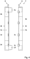
- the shell parts 2a, 2b are provided with integral connecting means 2c, 2d (made in one piece there-with), particularly snap fingers 2c of one shell 2a arranged to releasingly hold the opposite shell 2b via respective snap grooves 3d (see Fig. 4 ) when the box 2 is in the closed condition.
- the connecting means 2c, 3d can be configured such that the box 2 retains its closed condition, counteracting spring forces of the compressed sealing means 3.
- the box 2 is provided with a set of spaced-apart connecting means; in the example, each of the box sections 2T, 2M, 2L has respective connecting means 2c, 2d (and at opposite lateral side walls 2s).
- the two box parts 2a, 2b can be pivotally connected to each other (to be pivoted between an open and closed condition), using one or more suitable hinges, for example integral hinges (made in one piece with those parts).
- the assembly includes a dedicated mounting device 9, for example a clamping and/or locking device 9, for mounting (clamping and/or locking) the box 2 to the tube 1.
- a dedicated mounting device for example a clamping and/or locking device 9, for mounting (clamping and/or locking) the box 2 to the tube 1.
- the box 2 is provided with a mounting section 8 for receiving the mounting device 9.
- the mounting section 8 is integral part (made in one piece with) the neck portion 3T of the box 2.
- the mounting device is a flexible ty-rap clamping strip 9.
- the mounting section 8 can include a pair of opposite (in this case L-shaped) fingers 8 extending away from the chamber 4, from box side that includes an afore-mentioned duct passage 5.
- the width of each of the fingers 8 is preferably smaller that the external diameter D of the duct 1 to be held.
- each finger 8 is formed by two finger parts of opposite box parts 2a, 2b, joined together when the box is in the closed condition.
- the mounting device 9 acts as a locking device, for locking the box in the closed state.
- the mounting method preferably comprises positioning a duct section in the distribution box 2, when the box 2 is in the opened condition (i.e. when the two shells 2a, 2b are removed from each other, in an disassembled initial state).
- the sealing means 3 can be installed on the duct 1, after which the shells 2a, 2b are mounted.
- a distribution chamber 4, defined within the distribution box can be hermetically sealed from the environment of the distribution box, by closing the box (i.e. by adjusting the box from the initial state to a sealing state, the adjustment of the distribution box 2 leading to the sealing of the distribution chamber 4).
- the resilient sealing means material is being compressed by the adjustment of the distribution box, the compressed resilient material providing the sealing of the distribution chamber, along edges of the shells 2a, 2b, and with the primary duct 1 at respective duct passages 5.
- assembly includes the coupling of one or more microducts 15 to the distribution box 2 at the respective ports 6, for receiving one or more signal conductors 16 from the distribution chamber 4.
- a seal is the provided between an outer surface of each secondary duct 15 and the distribution box 2, by the sealing means 3.
- Ports 6 that are not used are closed as well with above-mentioned closing means, for example plugs 3e.
- signal conductor distribution is achieved, via a hermetically closed system (at least, hermetically closed at the distribution location of the distribution box).
- the mounting of the present distribution box 2 can be carried out swiftly, using only a few straightforward operator steps, utilizing clamping/locking of the box 2 to the primary duct 1 at only a single fixation point (using the mounting device 9).
- a fully dividable box 2 is provided, for example consisting of two shells 2a, 2b with one or more sealing means (for example inlay's 3 of soft material) provided at primary duct entry openings 5, as well as at the microduct ports 6 and along (between) contact area of the two shells 2a, 2b.Also, the box 2 is constructed to be installed on a through passing primary duct 1.
- the sealing means 3 can ensure gastight entries for the various ducts 1, 15.
- a second duct 1' a different external diameter D' (in this case a smaller diameter D') than the diameter D of the duct 1 shown in Figure 1 .
- the assembly comprises a first distribution box 2 that is configured to provide a fluid-tight engagement with the first duct 1, and a second distribution box 2' that is configured provide a fluid-tight engagement with the second duct 1'.
- at least some parts of the second distribution box 2' are the same as respective parts of the first distribution box 2.
- the second distribution box 2' includes the two box parts, for example the shells 2a, 2b, of the first distribution box 2, as well as a respective second sealing means 3' that is adapted to provide a sealing engagement with the second duct 1' (at respective sealing sections 3T', 3L').
- the primary duct passages 3a' of the second sealing means 3' have a different cross-section than the primary duct passages 3a of the first sealing means 3, for receiving the second duct 1' with no or almost no mismatch.
- a dedicated sealing means 3, 3' can be designed, enabling the distribution box 2 to be installed on a range of such ducts.
- secondary ducts 15 of different external diameters can be available.
- dedicated sealing means 3 can be designed (having dedicated duct receiving ports 6), enabling the distribution box 2 to be installed on a range of such ducts 15.
- primary ducts 1, 1' having circular cross-sections have been discussed.
- a primary duct can have another external shape (when viewed in cross-section), for example oval, polygonal, square, rectangular, or differently.
- a secondary ducts (for example a microduct 15) is preferably provided with a circular external cross-section, however, that shape can also be oval, polygonal, square, rectangular, or a different shape.
Landscapes
- Physics & Mathematics (AREA)
- General Physics & Mathematics (AREA)
- Optics & Photonics (AREA)
- Light Guides In General And Applications Therefor (AREA)
- Installation Of Indoor Wiring (AREA)
- Duct Arrangements (AREA)
Description
- The invention relates to an assembly comprising at least one primary duct and at least one distribution box.
- Applicant's
EP2108987A1 discloses an optical box comprising a first part suitable for fastening to an optical fibre distribution cable, and a second part having an opening intended for the passage of at least one optical fibre dropped from the distribution cable and comprising at least one optical component for connecting the dropped optical fibre to at least one optical fibre of a subscriber cable. The second part of the optical box is fastened detachably to the first part of the optical box. The known optical box (also called a "distribution box") makes it possible to combine the dropping and splicing of optical fibres, which is discreet and compact whilst allowing easy and efficient handling by the installation operator. - High-capacity telecommunication cables are used in optical fibre telecommunication systems all the way to the user, known under the English acronym FTTH for "Fiber To The Home" or FTTC for "Fiber To The Curb", and an Individual access to each micromodule and/or each fibre is realized for a distribution into a particular building or a particular floor. In this context, by "distribution cable" is meant a telecommunication cable containing a plurality of fibres which are grouped in micromodules supplying an optical signal to a whole building or a group of buildings. The distribution cable can in particular be a vertical cable installed in the service shaft of a building or an external cable installed in urban conduits. The distribution cable can contain several tens of optical fibres. A known distribution cable is a duct, for example having one or more channels that are enclosed by a duct wall, one or more of the channels including one or more fibres.
- By "subscriber cable" is meant a cable containing one or more optical fibres connected to a subscriber box. A subscriber cable generally contains less than 10 optical fibres. A distribution box can supply a whole building, a whole floor or a particular apartment. The distribution cable is generally installed in a service shaft and the subscriber box is installed in each subscriber's premises, at some distance from the distribution cable. In order to connect the fibres of a subscriber cable to the fibres of the distribution cable, typically, a drop cable is used, from the distribution cable to a splicing box in which the bare fibres of the drop cable and of the subscriber cable are connected.
- A problem of a prior art assembly is a risk of transport of gasses (for example dangerous, toxic and/or flammable gasses, and/or smoke in case of a fire) from one floor in a multi dwelling unit other floors in the building. Besides, a known distribution box is designed to be installed on one type of riser cable (having one predetermined cable diameter). Thus, different distribution boxes are required for application on different types of cables. Also, an existing distribution box requires different points of fixation to the riser cable, or it must be mounted to a wall. Therefore, installation of a known distribution box can be cumbersome.
- The present invention aims to solve or at least alleviate the above-mentioned problems. One aim of the invention is to reduce the risk of spreading of gasses, and/or to reduce spreading of a fire. Also, an object of the invention is to provide an efficient way of installing a distribution box, utilizing relatively little installation time.
-
US2008/0056661 discloses a duct closure for sealing the end of a duct. The duct is typically placed underground with pulling tape inside, wherein the pulling tape is used to pull lengths of cable into the duct. -
WO2009/029258 discloses an enclosure assembly, having an entry port and an exit port for receiving an optical fiber cable. Also, different sides are provided with ports for receiving drop cables. -
US2008/181570 discloses a multi-drop closure system for fiber optic cabling including an enclosure and a ganged drop plug. The enclosure defines a splice chamber therein and has a main cable access opening and a drop cable access opening into the splice chamber, the drop cable access opening being displaced from the main cable access opening. -
WO2009/113112 A1 discloses a method for connecting user devices to optical fiber units contained in an optical cable, solving the problem of how to provide a suitable protection of the optical fibers extracted from an optical cable, typically already installed in the field, using a protection tube of suitable characteristics. - According to the present invention, to this aim, there is provided an assembly, subject-matter of
claim 1. The assembly comprises at least one primary duct including one or more optical signal conductors, and at least one distribution box, the distribution box being mounted on the primary duct, in fluid-tight engagement there-with, for enclosing a distribution chamber therewith, particularly such that the distribution chamber is hermetically sealed from an environment of the distribution box, wherein the distribution box comprises two box parts, for example shells, that engage the primary duct from two sides, wherein the distribution box has two primary duct passages for feeding the primary duct through the box, wherein the assembly is characterised in that only one side of the distribution box has secondary duct receiving passages, configured for passing proximal end sections of secondary ducts there-through, towards the distribution chamber, wherein the distribution box has a first section and an opposite second section, the first distribution box section being a relatively narrow neck portion and the second distribution box section being a relatively wide portion having the number of secondary duct receiving passages, wherein both the first section of the distribution box and the opposite second section are provided one of the primary duct passages.
Thus, risk of spreading of certain gasses, for example between different levels of a building, can be significantly reduced. Thus, in case of a fire, undesired spreading of hot gasses and smoke between different levels of a building via a part of a fibre optic network that contains the (usually hollow) duct and the distribution box can be prevented very well. - Also, in a preferred embodiment the assembly includes a least one hollow microduct that is coupled to the distribution box for receiving at least one signal conductor from the distribution chamber. For example, said signal conductor can be a signal conductor that extends via a main duct into the distribution chamber, with or without local splicing. A blocking structure can be provided for blocking passage of a proximal microduct edge, for example for locally positioning a proximal end of the microduct. The blocking structure is preferably provided with a through-hole for passing a signal conductor from the distribution chamber to a microduct (that engages the blocking structure). Also, preferably, the blocking structure can be configured as a sealing means.
- According to a preferred embodiment the assembly comprises a resilient sealing material, the resilient sealing material sealing the distribution chamber from an environment of the distribution box.
- For example, the sealing material can be compressed by the distribution box and the duct, to seal the distribution chamber from it's (local) environment.
- Thus, a reliable seal can be achieved. Also, the sealing material can be used to accommodate ducts having different external duct diameters, so that the same distribution box can be mounted on different types of ducts.
- According to an aspect of the invention, there is provided a method, subject-matter of claim 13. The method of mounting a distribution box to a duct, at a distribution point that is spaced-apart from duct ends, comprises:
- positioning a distribution point duct section in the distribution box; and
- hermetically sealing a distribution chamber, defined within the distribution box, from an environment of the distribution box,
- With the assembly and the method according to the invention, the above-mentioned aim and objective can be advantageously achieved.
- Further advantageous embodiments of the invention are described in the dependent claims.
- The invention will now be described in more detail on the basis of exemplary embodiments shown in the accompanying drawing. Therein shows:
-
Fig. 1 a front view of part of a non-limiting embodiment of an assembly according to the invention; -
Fig. 2 a front view of the distribution box of the embodiment shown inFig 1 ; -
Fig. 3 a bottom view of the distribution box shown inFig. 2 , in an assembled condition; -
Fig. 4 a side view of the distribution box shown inFig. 2 , in a disassembled condition; -
Fig. 5 a longitudinal cross-section of a resilient sealing material of the assembly ofFig. 1 ; -
Fig. 6 a bottom view of the sealing material shown inFig. 5 , before installation; and -
Fig. 7 a view similar toFig. 1 , with another primary duct. - Equal or corresponding features are denoted by equal or corresponding reference signs in this application.
- Figure ldepicts an assembly comprising a
primary duct 1 and a distribution box 2 (shown in part), thedistribution box 2 being mounted on theduct 1. - The
primary duct 1 is a distribution duct (for example a "drop cable" or "riser cable"). After actual mounting, theduct 1 may extend between various floors of a building. Theduct 1 can include one or more channels (in this case one) that are enclosed by a duct wall, one or more of the channels including one or more (elongated)signal conductors 16. The duct wall of theduct 1 has been provided with an opening 1a (a "tapping window", for example a longitudinal slit, locally cut out of the duct 1) for providing access to the duct's interior, the opening being located in thedistribution box 2 after assembly. As follows from the drawing, the opening 1a does not interrupt the duct 1 (i.e., part of the duct wall bridges the opening la). Optionally, the external surface of eachsignal conductor 16 is not attached to the internal surface of theprimary duct 1, such, that at least part of thesignal conductor 16 can be moved in longitudinal directions through the duct 1 (for example during installation). In a further embodiment, the at least onesignal conductor 16 andduct 1 are installed simultaneously, for example vertically, in a building. In another embodiment, during installation, thesignal conductor 16 are (simply) dropped into a mountedduct 1, particularly in a vertical or substantiallyvertical duct 1, or in a vertical or substantially vertical section thereof. - In yet a further, preferred, embodiment, during installation the
duct 1 is provided with another opening (not shown), spaced apart from the tappingwindow 1a, for gaining access to the at least onesignal conductor 16 that extends through theduct 1, particularly for locally cutting thatsignal conductor 16. For example the further duct opening can be provided substantially at another floor level of a building with respect to a floor level location of a tapping window la. Then, after cutting, part of thecut signal conductor 16 can be retracted from theduct 1 via the tappingwindow 1a, towards and into a respective secondary duct 15 (seeFig. 1 ). - Preferably, in case of application of a plurality of
signal conductors 16, the signal conductors are provided with external markings or indicators (for example by color coding) so that they can be (visually) differentiated from each other. -
Figure 1 also shows application ofsecondary ducts 15, for example tubes, called "microducts", for guidingsignal conductors 16 from theduct 1 to remote locations (for example end-user locations). Generally, in case of application ofducts primary duct 1, for example at least twice as small. Typically, an external diameter of a microduct can be about 5 mm, or smaller. An external diameter D of aprimary duct 1 can be larger than 5 mm, for example in the range of 7-15 mm, or larger than 15 mm. - Preferably, each
microduct 15 is configured to (axially) movably receive at least part of a respective signal conductor 16 (for example aconductor 16 that is guided through theprimary duct 1 during installation). To this aim, eachmicroduct 15 encloses an internal receiving space, having a diameter that is larger than an external diameter of the respectiveoptical signal conductor 16. - In the present example, signal
conductors 16 are shown that are guided between theprimary duct 1 and themicroducts 15 without intermediate splicing (i.e. in a locally unbroken condition). Thus, relatively little installation space and relatively little installation time is required. In another embodiment, an optical component (for example a local mechanical splice, a fusion splice, an optical splitter) can be installed to connect a signal conductor emanating -via the opening la-from theprimary duct 1 to a signal conductor that extending into amicroduct 15. - Each of the
signal conductors 16 as such can be configured in various ways. Eachsignal conductor 16 can be or include an optical fiber, or a plurality of optical fibers, or a cable comprising one or more optical fibers (providing one or more respective optical waveguides, for transmitting optical signals), for example enclosed within a buffer tube. For instance, said optical fiber may be deployed in either a single fiber loose buffer tube or a multi-fiber loose buffer tube. In other embodiments, the buffer tube may tightly surround an outermost optical fiber coating (i.e., tight buffered fiber) or otherwise surround an outermost optical fiber coating or ink layer to provide an exemplary radial clearance of between about 50 and 100 microns (i.e., a semi-tight buffered fiber). With respect to the former tight buffered fiber, the buffering may be formed by coating the optical fiber with a curable composition (e.g., a UV-curable material) or a thermoplastic material. The outer diameter of tight buffer tubes, regardless of whether the buffer tube is formed from a curable or non-curable material, is typically less than about 1,000 microns (e.g., either about 500 microns or about 900 microns). With respect to the latter semi-tight buffered fiber, a lubricant may be included between the optical fiber and the buffer tube (e.g., to provide a gliding layer). - An exemplary buffer tube enclosing optical fibers as disclosed herein may be formed of polyolefins (e.g., polyethylene or polypropylene), including fluorinated polyolefins, polyesters (e.g., polybutylene terephthalate), polyamides (e.g., nylon), as well as other polymeric materials and blends. In general, a buffer tube may be formed of one or more layers. The layers may be homogeneous or include mixtures or blends of various materials within each layer.
- In this context, the buffer tube may be extruded (e.g., an extruded polymeric material) or pultruded (e.g., a pultruded, fiber-reinforced plastic). By way of example, the buffer tube may include a material to provide high temperature and chemical resistance (e.g., an aromatic material or polysulfone material).
- Although buffer tubes typically have a circular cross section, buffer tubes alternatively may have an irregular or non-circular shape (e.g., an oval or a trapezoidal cross section).
- Alternatively, one or more of the present optical fibers may simply be surrounded by an outer protective sheath or encapsulated within a sealed metal tube. In either structure, no intermediate buffer tube is necessarily required.
- Multiple optical fibers as disclosed herein may be sandwiched, encapsulated, and/or edge bonded to form an optical fiber ribbon. Optical fiber ribbons can be divisible into subunits (e.g., a twelve-fiber ribbon that is splittable into six-fiber subunits). Moreover, a plurality of such optical fiber ribbons may be aggregated to form a ribbon stack, which can have various sizes and shapes.
- Generally, each of the fibers includes a fiber core and a respective cladding of glass, and one or more optional coatings. Optionally, the optical fiber may include an outermost ink layer. Also, a
signal conductor 16 can include a single fibre, for example having a respective external protective fibre coating. - Preferably, "bend-insensitive" fibers (such as ITU-T G657 fibers) are applied, which may buckle (for example due to thermal fluctuations) or bend over a small radius with relatively little or no optical attenuation.
- Each of the
microducts 15 can be a hollow tube or duct, for example made of plastic (for example High Density Polyethylene, HDPE), configured for loosely receivingsignal conductor 16. Preferably, the external surface of thesignal conductor 16 is not attached to the internal surface of themicroduct 15, such, that thesignal conductor 16 can be moved in longitudinal directions through the microduct. In the present example, theexternal microduct 15 may have a circular cross-section; the microduct's cross-section can also have a different shape, for example oval, rectangular, hexagonal, or differently. - Each
microduct 15 is preferably flexible or bendable, allowing ease of installation. Also, the microduct is preferably constructed such that its bending radius is limited. Preferably, a radial and longitudinal freedom of thesignal conductor 16 with respect to themicroduct 15 is available, to make thesignal conductor 16 relatively resistant to rough installation practices. - Referring to the configuration of the
distribution box 2, particularly, thedistribution box 2 is mounted on theprimary duct 1, in fluid-tight (particularly gas-tight) engagement there-with,distribution box 2 being configured for enclosing adistribution chamber 4 with theprimary duct 1. Thedistribution chamber 4 provides space for guiding (and bending)signal conductors 16 between thelocal duct opening 1a and thesecondary ducts 15, for example using a local S-shaped bending of theseconductors 16, as inFig. 1 . - In the present example, the
distribution chamber 4 is hollow (for example being filled with a gas or gas mixture, for example air).The volume of thedistribution chamber 4 can remain relatively small in the case that it does not have to contain above-mentioned optical components (such as splices) for locally connecting conductor parts. - The
present distribution box 2 comprises two box parts, forexample shells box 2 onto theduct 1, as well as a gas tight closure for the box as such. - In
Fig.1 , thedistribution box 2 is depicted with afront part 2a being removed, thefront part 2a being shown inFig. 2 . Also,Fig. 1 shows the sealing means in longitudinal cross-section. - The
box parts box part main wall 2k, andside walls 2s protruding from an edge of themain wall 2k, theside walls 2s of theopposite box parts - The
distribution box 2 has two primary duct passages 5 (seeFig. 1 ), located in opposite sides of the box, so that a section of theprimary duct 1 can pass through the box 2 (i.e. into and out of the chamber 4). In the present example, theduct passages 5 are located in line with each other, in particular coaxially with a centre line of thebox 2, so that theduct 1 can be fed centrally through thechamber 4 in straight line (as inFig. 1 ). Also, in this example, each primary duct passage 5 (in this case having a circular cross-section) is defined by two opposite apertures (in this case semi-circular apertures) in respective side walls of the twodistribution box parts primary duct passages 5 are both located in a virtual longitudinal plane that intersects opposite edges of theshells Fig. 3 ). - The
distribution box 2 may have various configurations and shapes. For example, the when viewed in a front view, thedistribution box 2 may have a polygonal, rectangular, rounded, oval, circular, or a combination of such shapes, or differently shaped external form (outline). As follows from the drawing and according to the invention, the distribution box has afirst section 2T and an oppositesecond section 2L. The firstdistribution box section 2T is a relatively narrow neck portion (having a first width W1) that includes a firstprimary duct passage 5. The seconddistribution box section 2L is a relatively wide portion (i.e. having a second width W2 that is larger than the width W1 of thefirst box section 2T, for example at least twice as large), and (centrally) includes a secondprimary duct passage 5, as well as a number of ports for receiving saidmicroducts 15. Anintermediate box section 2M extending between the first andsecond box section - The ports are provided by
microduct receiving passages 6, configured for passing proximal end sections of distribution lines (i.e. the microducts 15) there-through, towards thechamber 4. Thedistribution box 1 can be provided with various numbers of such passages, for example any of the integer range {1, 2, 3, 4, ...., 10} or another number. In the example, thepassages 6 are located on opposite lateral sides with respect to the primary duct passage 5 (seeFig. 3 ). - Preferably, as in the present embodiment, the
microduct receiving passages 6 are symmetrically arranged with respect to a (central)primary duct passage 5. Preferably, an even number ofsuch receiving passages 6 is provided. According to the invention, only one side of the distribution box 2 (in this case a top side, which is faced upwardly after mounting) is provided with themicroduct receiving passages 6, particularly in addition to a respective primary duct passage 5 (wherein an opposite, lower, side is only provided with a primary duct passage 5). - In the present example, the each
microduct receiving passages 6 extend in parallel with each other, and also in parallel with theprimary duct passages 5. Alternatively, microduct receiving passages can extend in mutually different directions. In another, preferred, embodiment, for example,microduct receiving passages 6 are all arranged such that they are directed towards theduct opening 1a after assembly (i.e. towards a central area of the chamber 5), so that bending of thesignal conductors 16 can be reduced. Also alternatively, theprimary duct passages 5 may extend in a different direction than microduct receiving passages. - Similar to the
primary duct passage 5, in this example, each microduct receiving passage 6 (in this case having a circular cross-section) is defined by two opposite apertures (in this case semi-circular apertures) in respective side walls of the twodistribution box parts passages 6 also located in the afore-mentioned virtual longitudinal plane that intersects opposite edges of theshells Fig. 3 ). In the present example, the centre points of thepassages 6 are arranged in-line with each other. It will be appreciated that themicroduct receiving passages 6 can also have another mutual arrangement. - Also, as a non limiting example, a transversal width W2 (viewed in a front view) of the
box 2 can be larger than a maximum duct diameter of theduct 1 that can be received. In the present example, a maximum box width W2 (i.e. the width of the second box section) can for example depend on a number ofsignal conductors 16 that is to be accommodated, in addition to the maximum duct diameter. - A height H of the box 2 (indicated with arrow H in
Fig., 3 , the height direction being orthogonal with respect to the box width and box length directions) can be larger than a diameter D of theduct 1 to be mounted to. In the present example, the box height can be smaller than three times said duct diameter D, for example smaller than two times said duct diameter D (seeFig. 3 ). In a further embodiment, the box height H can be about the same as the width W1 of the afirst box section 2T (for example in the range of the width W1 +/- 25% of that width Wl). Thus, a relatively compact,flat distribution box 1 can be achieved, providing an efficient handling and assembly. - In the example, the afore-mentioned sealing means 3 are configured for hermetically sealing the closed distribution box 2 (after assembly with the primary and
secondary ducts 1, 15), to prevent gas exchange between thedistribution chamber 4 and the local environment of thedistribution box 2. - Particularly, the sealing means 3 can be configured for sealing an external surface of the
primary duct 1 to thedistribution box 2. The sealing means 3 can be configured in various ways. For example, the sealing means can comprise one or more gaskets or inlays of aresilient sealing material 3, theresilient sealing material 3 being compressed between the twoopposite box sections distribution box 2 and the external surface of theprimary duct 1, and between thedistribution box 2 and external surfaces of proximal sections of anymicroducts 15, after mounting, to hermetically seal thechamber 4 from a local environment of thedistribution box 2. As a result of the sealing, spread of hazardous gasses (for example toxic gasses, smoke during a fire) via the system -provided by the distribution box- and/or draught can be prevented. - As follows from
Figure 5 , the present sealing means 3 (such as a gasket or inlay) includes afirst section 3T, that is received in the firstdistribution box section 2T after mounting (between the twobox parts second section 3L, which is received in the seconddistribution box section 3L between the twobox parts intermediate section 3M (received between the twobox parts intermediate box section 2M). After assembly, thefirst section 3T may be arranged vertically above thesecond section 3L, as inFigure 1 . Alternatively, after assembly, thefirst section 3T may be located vertically below thesecond section 3L. - The sealing means
sections opposite box shells respective box sections distribution box 2, to seal thesesections opposite box shells shells - In the embodiment, the
first section 3T of the sealing means 3 includes afirst passage 3a, arranged in-line with (in the example concentrically) with theprimary duct passages 5 of theshell parts first passage 3a is provided in thesecond section 3L of the sealing means 3. Thefirst passages 3b of the sealing means 3 are configured to match the external shape of theprimary duct 1, preferably for seamlessly enclosing thatduct 1 before assembly. Preferably, the first and second sealing meanssections duct 3a during the closing of the distribution box 2 (i.e. during assembly), to provide fluid-tight engagement therewith (and a respective fluid-tight closure of the distribution box). - Also, the second sealing means
section 3L is provided withsecondary passages 3b that arranged in-line with (in the embodiment concentrically) with themicroduct receiving passages 6 of theshell parts secondary passages 3b of the sealing means 3 are configured to match the external shapes of themicroducts 15, preferably for seamlessly enclosing thatduct 1 before assembly. Preferably, the second sealing meanssection 3L is dimensioned to be pressed ontomicroducts 15 extending into thesepassages 6 during the closing of thedistribution box 2, to provide fluid-tight engagement therewith (and a respective fluid-tight closure of the distribution box). - The present embodiment includes a blocking structure for blocking axial passage of the proximal ends of the
microducts 15. In the present example, thesecondary passages 3b lead towards distal microduct stop surfaces of the sealing means 3, for blocking passage of proximal microduct edges. As follows fromFigures 1 ,5 , in the embodiment, the present stop surfaces are conical. Through-holes 3d are in the stop surfaces, for passingsignal conductors 16 from thechamber 4 torespective microducts 15. - Optionally, one or more of the
duct passages lateral slits 3c, extending to an outer side of the sealing means 3 (seeFig. 6 ).Such slits 3c can enhance local compressibility of the sealing means 3, particularly for reducing cross-sections ofrespective passages box 2. Theslits 3c are closed after assembly, when the sealing means 3 is in the compressed condition between thebox parts - Also, preferably, closing means 3e are available, for closing the
secondary passages 3b that are not in use (i.e., which remain empty, and do not receive a microduct end). Such closing means can be configured in various ways. Preferably, the closing means can be removably applied, so that apassage 3b closed thereby can be made operational at a later stage. For example, suitable closing means can include a sealing tape, a covering, sealing kit,insertable plug 3e (as in the present example), or another suitable closing means. In the present example, the sealing means 3 as such can be provided with a set of (optionally resilient) closing plugs 3e. In the example, the sealing means 3 andclosing plugs 3e are made in one piece, of the same material. Theplugs 3e can be removed from a remainder of the sealing means 3 before assembly. Then, during assembly, selectedsecondary passages 3b can simply be hermetically closed using the readily available (matching) plugs 3e. - In one embodiment, a single sealing means 3 is provided, to be installed in the
box 2 to achieve the sealing. In a further embodiment, the sealing means 3 is removable from thebox 2, for example to be replaced. - Also, in a further embodiment, the sealing means can be composed of several sealing sections. For example, each of the
box parts box 2 is in the opened condition. - In the present example, connecting means 2c, 2d are provided, configured to connect the two
box sections box 2 is mounted on theduct 1. The connecting means can be configured in various ways. Preferably, the connecting means are configure to provide a connection that can be manually undone in simple manner, with relatively little force. The connecting means can include one or more of: clicking connections, snapping means, threaded connectors, connecting pins, Velcro® connecting devices, one or more bendable or flexible connecting wires, or different connecting means. In the example, theshell parts means fingers 2c of oneshell 2a arranged to releasingly hold theopposite shell 2b viarespective snap grooves 3d (seeFig. 4 ) when thebox 2 is in the closed condition. The connecting means 2c, 3d can be configured such that thebox 2 retains its closed condition, counteracting spring forces of the compressed sealing means 3. Preferably, thebox 2 is provided with a set of spaced-apart connecting means; in the example, each of thebox sections means lateral side walls 2s). - Optionally, the two
box parts - Further, the assembly includes a
dedicated mounting device 9, for example a clamping and/or lockingdevice 9, for mounting (clamping and/or locking) thebox 2 to thetube 1. To this aim, thebox 2 is provided with a mountingsection 8 for receiving the mountingdevice 9. In the example, the mountingsection 8 is integral part (made in one piece with) theneck portion 3T of thebox 2. Particularly, the mounting device is a flexible ty-rap clamping strip 9. Thus, a swift clamping (and in this case locking of the box 2) can be achieved, using inexpensive means. - For receiving the
clamping strip 9, for example, the mountingsection 8 can include a pair of opposite (in this case L-shaped)fingers 8 extending away from thechamber 4, from box side that includes an afore-mentionedduct passage 5. The width of each of the fingers 8 (inFig. 1 measured normally with respect to the plane of the drawing) is preferably smaller that the external diameter D of theduct 1 to be held. - A relatively stable configuration is achieved in case the mounting
device 9 connects bothbox parts finger 8 is formed by two finger parts ofopposite box parts device 9 acts as a locking device, for locking the box in the closed state. - Mounting of the
distribution box 2 to aprimary duct 1 can be at a point that is spaced-apart from duct ends (not shown). The mounting method preferably comprises positioning a duct section in thedistribution box 2, when thebox 2 is in the opened condition (i.e. when the twoshells duct 1, after which theshells distribution chamber 4, defined within the distribution box, can be hermetically sealed from the environment of the distribution box, by closing the box (i.e. by adjusting the box from the initial state to a sealing state, the adjustment of thedistribution box 2 leading to the sealing of the distribution chamber 4). Herein, the resilient sealing means material is being compressed by the adjustment of the distribution box, the compressed resilient material providing the sealing of the distribution chamber, along edges of theshells primary duct 1 atrespective duct passages 5. - Moreover, assembly includes the coupling of one or more microducts 15 to the
distribution box 2 at therespective ports 6, for receiving one ormore signal conductors 16 from thedistribution chamber 4. A seal is the provided between an outer surface of eachsecondary duct 15 and thedistribution box 2, by the sealing means 3.Ports 6 that are not used are closed as well with above-mentioned closing means, forexample plugs 3e. As a result, signal conductor distribution is achieved, via a hermetically closed system (at least, hermetically closed at the distribution location of the distribution box). - As a result, risk of transporting gasses (dangerous/flammable) from one floor in a multi dwelling unit to other floors in the building (via the hollow distribution duct 1) can be significantly reduced. Moreover, the mounting of the
present distribution box 2 can be carried out swiftly, using only a few straightforward operator steps, utilizing clamping/locking of thebox 2 to theprimary duct 1 at only a single fixation point (using the mounting device 9). - As follows from the above, in an embodiment, a fully
dividable box 2 is provided, for example consisting of twoshells duct entry openings 5, as well as at themicroduct ports 6 and along (between) contact area of the twoshells 2a, 2b.Also, thebox 2 is constructed to be installed on a through passingprimary duct 1. The sealing means 3 can ensure gastight entries for thevarious ducts - In a further embodiment, following from
Fig. 7 , there can be provided asecond duct 1' a different external diameter D' (in this case a smaller diameter D') than the diameter D of theduct 1 shown inFigure 1 . In that case the assembly comprises afirst distribution box 2 that is configured to provide a fluid-tight engagement with thefirst duct 1, and a second distribution box 2' that is configured provide a fluid-tight engagement with thesecond duct 1'. In that case, preferably, at least some parts of the second distribution box 2' are the same as respective parts of thefirst distribution box 2. In the present example, the second distribution box 2' includes the two box parts, for example theshells first distribution box 2, as well as a respective second sealing means 3' that is adapted to provide a sealing engagement with thesecond duct 1' (atrespective sealing sections 3T', 3L'). Particularly, theprimary duct passages 3a' of the second sealing means 3' have a different cross-section than theprimary duct passages 3a of the first sealing means 3, for receiving thesecond duct 1' with no or almost no mismatch. - Thus, for the
primary duct distribution box 2 to be installed on a range of such ducts. - Similarly, in a further embodiment,
secondary ducts 15 of different external diameters can be available. Then, also for suchsecondary ducts 15, dedicated sealing means 3 can be designed (having dedicated duct receiving ports 6), enabling thedistribution box 2 to be installed on a range ofsuch ducts 15. - Although the illustrative embodiments of the present invention have been described in greater detail with reference to the accompanying drawings, it will be understood that the invention is not limited to those embodiments. Various changes or modifications may be effected by one skilled in the art
without departing from the scope of the invention as defined in the claims. - It is to be understood that in the present application, the term "comprising" does not exclude other elements or steps. Also, each of the terms "a" and "an" does not exclude a plurality. Any reference sign(s) in the claims shall not be construed as limiting the scope of the claims
- For example, in the present examples,
primary ducts - Similarly, a secondary ducts (for example a microduct 15) is preferably provided with a circular external cross-section, however, that shape can also be oval, polygonal, square, rectangular, or a different shape.
Claims (15)
- An assembly comprising at least one primary duct (1) including one or more optical signal conductors (16), and at least one distribution box (2), the distribution box (2) being mounted on the primary duct (1), in fluid-tight engagement there-with, for enclosing a distribution chamber (4) therewith, wherein the distribution box (2) comprises two box parts, for example shells, (2a, 2b) that engage the primary duct from two sides, wherein the distribution box (2) has two primary duct passages (5) for feeding the primary duct (1) through the box (2), characterised in that only one side of the distribution box (2) has secondary duct receiving passages (6), configured for passing proximal end sections of secondary ducts (15) there-through, towards the distribution chamber (4),
wherein the distribution box has a first section (2T) and an opposite second section (2L), the first distribution box section (2T) being a relatively narrow neck portion and the second distribution box section (2L) being a relatively wide portion having the number of secondary duct receiving passages (6),
wherein both the first section (2T) of the distribution box (2) and the opposite second section (2L) are provided with one of the primary duct passages (5). - The assembly according to claim 1, wherein the secondary duct receiving passages (6) are symmetrically arranged with respect to the primary duct passage (5).
- The assembly according to claim 1 or 2, having connecting means (2c, 2d) configured to connect the two box parts (2a, 2b) to each other when the box (2) is mounted on the primary duct (1).
- The assembly according to any of the preceding claims, wherein each secondary duct receiving passage (6) is defined by two opposite apertures in respective side walls of the two distribution box parts (2a, 2b).
- The assembly according to any of the preceding claims, having a dedicated clamping and/or locking device (9) for clamping and/or locking the box (2) to the primary duct (1), for example a ty-rap clamper.
- The assembly according to claim 5, wherein the dedicated clamping and/or locking device (9) is a mounting device (9) for connecting both box parts (2a, 2b) to each other.
- The assembly according to any of the preceding claims, the distribution box (2) comprising sealing means (3) for sealing an external surface of the primary duct (1) to the distribution box (2).
- The assembly according to any of the preceding claims, comprising a resilient sealing material (3), the resilient sealing material (3) sealing the distribution chamber (4) from an environment of the distribution box (2).
- The assembly according to any of the preceding claims, comprising at least a first primary duct (1) and a second primary duct (1') having mutually different external diameters (D, D'), the assembly comprising a first distribution box (2) that is configured to provide a fluid-tight engagement with the first primary duct (1), and a second distribution box (2') that is configured to provide a fluid-tight engagement with the second primary duct (1').
- The assembly according to any of the preceding claims, comprising sealing means (3) configured for hermetically sealing the closed distribution box (2) after assembly with the primary and secondary ducts (1, 15), in particular to prevent gas exchange between the distribution chamber (4) and the local environment of the distribution box (2), the sealing means (3) for example comprising one or more gaskets or inlays of a resilient sealing material (3), the resilient sealing material (3) being compressed between the two opposite box parts (2a, 2b), between the distribution box (2) and the external surface of the primary duct (1), and between the distribution box (2) and external surfaces of proximal sections of any secondary ducts (15), after mounting.
- The assembly according to claim 10, wherein the sealing means (3) includes a first section (3T), that is received in the first distribution box section (2T) between the two box parts (2a, 2b) after mounting, an opposite second section (3L), which is received in the second distribution box section (2L) between the two box parts (2a, 2b), and an intermediate section (3M), received between the two box parts (2a, 2b) at an intermediate box section (2M), wherein the sealing means sections (3T, 3L, 3M) are dimensioned to be compressed between the opposite box parts (2a, 2b) at respective box sections (2T, 2L, 2M) during the closing of the distribution box (2) to seal these sections (2T, 2L, 2M) from the environment.
- The assembly according to claim 11, wherein the first section (3T) and the second section (3L) of the sealing means (3) include a first passage (3a), arranged in-line with, for example concentrically with, the primary duct passages (5) of the box parts (2a, 2b) after assembly, configured to match the external shape of the primary duct (1), preferably for seamlessly enclosing that duct (1) before assembly, and wherein the second section (3L) of the sealing means (3) includes secondary passages 3b, arranged in-line with, for example concentrically with, the secondary duct receiving passages (6) of the box parts (2a, 2b) after assembly, configured to match the external shapes of the secondary ducts (15), preferably for seamlessly enclosing these ducts (15) before assembly.
- A method of mounting a distribution box to a distribution duct, at a distribution point that is spaced-apart from duct ends, including the use of an assembly according to any of the preceding claims, the method comprising:- positioning a duct section in the distribution box (2);the method being characterised by hermetically sealing a distribution chamber (4), defined within the distribution box, from an environment of the distribution box (2),
coupling at least one secondary duct (15) to the distribution box (2) for receiving an optical signal conductor (16) from the distribution chamber (4), and providing a seal between an outer surface of the secondary duct (15) and the distribution box (2). - The method according to claim 13, the distribution box having an opened or disassembled initial state for receiving the duct section, wherein the distribution box is adjusted from the initial state to a sealing state after the duct section has been positioned in the distribution box, the adjustment of the distribution box leading to the sealing of the distribution chamber.
- The method according to claim 14, wherein a resilient material is being compressed by the adjustment of the distribution box, the compressed resilient material providing the sealing of the distribution chamber.
Applications Claiming Priority (1)
| Application Number | Priority Date | Filing Date | Title |
|---|---|---|---|
| NL2004694A NL2004694C2 (en) | 2010-05-10 | 2010-05-10 | An assembly comprising at least one duct and at least one distribution box, and a method of mounting a distribution box to a duct. |
Publications (2)
| Publication Number | Publication Date |
|---|---|
| EP2386894A1 EP2386894A1 (en) | 2011-11-16 |
| EP2386894B1 true EP2386894B1 (en) | 2019-03-13 |
Family
ID=43466389
Family Applications (1)
| Application Number | Title | Priority Date | Filing Date |
|---|---|---|---|
| EP11165404.2A Active EP2386894B1 (en) | 2010-05-10 | 2011-05-10 | An assembly comprising at least one duct and at least one distribution box, and a method of mounting a distribution box to a duct |
Country Status (6)
| Country | Link |
|---|---|
| US (1) | US8848347B2 (en) |
| EP (1) | EP2386894B1 (en) |
| ES (1) | ES2726768T3 (en) |
| HU (1) | HUE044195T2 (en) |
| NL (1) | NL2004694C2 (en) |
| PT (1) | PT2386894T (en) |
Families Citing this family (30)
| Publication number | Priority date | Publication date | Assignee | Title |
|---|---|---|---|---|
| MY154099A (en) | 2008-06-09 | 2015-04-30 | Flexsteel Pipeline Technologies Inc | Flexible pipe joint |
| CN102331609B (en) * | 2010-07-13 | 2015-05-27 | 泰科电子(上海)有限公司 | Optical fiber terminal box |
| RU2537708C2 (en) * | 2013-03-21 | 2015-01-10 | Закрытое Акционерное Общество "Связьстройдеталь" | Cable input of optical socket and method of using cable input |
| AU2015324083B2 (en) | 2014-09-30 | 2019-10-03 | Trinity Bay Equipment Holdings, LLC | Connector for pipes |
| RU2608597C1 (en) * | 2015-10-12 | 2017-01-23 | Российская Федерация, от имени которой выступает Государственная корпорация по атомной энергии "Росатом" (Госкорпорация "Росатом") | Sealed connector |
| US10088644B2 (en) * | 2015-10-28 | 2018-10-02 | Communications Systems, Inc. | Microduct coupling and termination |
| CN108474521B (en) | 2015-11-02 | 2021-04-09 | 柔性钢管道技术公司 | Real-time integrity monitoring of onshore pipelines |
| US10981765B2 (en) | 2016-06-28 | 2021-04-20 | Trinity Bay Equipment Holdings, LLC | Half-moon lifting device |
| US11208257B2 (en) | 2016-06-29 | 2021-12-28 | Trinity Bay Equipment Holdings, LLC | Pipe coil skid with side rails and method of use |
| WO2018071336A1 (en) | 2016-10-10 | 2018-04-19 | Trinity Bay Equipment Holdings, LLC | Installation trailer for coiled flexible pipe and method of utilizing same |
| CA3040103A1 (en) | 2016-10-10 | 2018-04-19 | Trinity Bay Equipment Holdings, LLC | Expandable drum assembly for deploying coiled pipe and method of using same |
| USD960115S1 (en) | 2017-04-20 | 2022-08-09 | University Of Tennessee Research Foundation | Tampering detection enclosure |
| USD826875S1 (en) * | 2017-04-20 | 2018-08-28 | University Of Tennessee Research Foundation | Tampering detection clamping box for ingress and egress lines |
| USD960114S1 (en) | 2017-04-20 | 2022-08-09 | University Of Tennessee Research Foundation | Tampering detection enclosure |
| US10345538B2 (en) | 2017-06-28 | 2019-07-09 | Sumitomo Electric Lightwave Corp. | System and method for joining and distributing a single optical fiber cable to multiple rack shelves |
| US10526164B2 (en) | 2017-08-21 | 2020-01-07 | Trinity Bay Equipment Holdings, LLC | System and method for a flexible pipe containment sled |
| US10261279B1 (en) | 2017-10-12 | 2019-04-16 | Sumitomo Electric Lightwave Corp. | System and method for distributing high fiber count optical cable to network racks |
| EP3703975A4 (en) | 2017-11-01 | 2021-07-21 | Trinity Bay Equipment Holdings, LLC | System and method for handling reel of pipe |
| BR112020015719A2 (en) | 2018-02-01 | 2020-12-08 | Trinity Bay Equipment Holdings, LLC | TUBE COIL ROAD WITH SIDE RAILS AND METHOD OF USE |
| MX2020008797A (en) | 2018-02-22 | 2021-01-08 | Trinity Bay Equipment Holdings Llc | System and method for deploying coils of spoolable pipe. |
| WO2020077201A1 (en) | 2018-10-12 | 2020-04-16 | Trinity Bay Equipment Holdings, LLC | Installation trailer for coiled flexible pipe and method of utilizing same |
| AR118122A1 (en) | 2019-02-15 | 2021-09-22 | Trinity Bay Equipment Holdings Llc | FLEXIBLE TUBE HANDLING SYSTEM AND METHOD TO USE THE SAME |
| US10753512B1 (en) | 2019-03-28 | 2020-08-25 | Trinity Bay Equipment Holdings, LLC | System and method for securing fittings to flexible pipe |
| US10926972B1 (en) | 2019-11-01 | 2021-02-23 | Trinity Bay Equipment Holdings, LLC | Mobile cradle frame for pipe reel |
| CN114945768A (en) | 2019-11-22 | 2022-08-26 | 圣三一海湾设备控股有限公司 | Swaged pipe fitting system and method |
| US11204114B2 (en) | 2019-11-22 | 2021-12-21 | Trinity Bay Equipment Holdings, LLC | Reusable pipe fitting systems and methods |
| EP4058712A4 (en) | 2019-11-22 | 2024-03-27 | Trinity Bay Equipment Holdings Llc | Potted pipe fitting systems and methods |
| US10822194B1 (en) | 2019-12-19 | 2020-11-03 | Trinity Bay Equipment Holdings, LLC | Expandable coil deployment system for drum assembly and method of using same |
| US10844976B1 (en) | 2020-02-17 | 2020-11-24 | Trinity Bay Equipment Holdings, LLC | Methods and apparatus for pulling flexible pipe |
| US11287580B1 (en) | 2020-09-16 | 2022-03-29 | Berk-Tek Llc | Armored cable and connection for the same |
Citations (1)
| Publication number | Priority date | Publication date | Assignee | Title |
|---|---|---|---|---|
| WO2009113112A1 (en) * | 2008-03-14 | 2009-09-17 | Prysmian S.P.A. | Method of connecting user devices to optical fibre units contained in an optical cable |
Family Cites Families (14)
| Publication number | Priority date | Publication date | Assignee | Title |
|---|---|---|---|---|
| US5397859A (en) * | 1993-12-10 | 1995-03-14 | The Whitaker Corporation | Enclosure with sealant for spliced coaxial cables |
| GB9414038D0 (en) * | 1994-07-11 | 1994-08-31 | Raychem Ltd | Electrical interconnection |
| AR001330A1 (en) * | 1994-12-12 | 1997-10-22 | Raychem Sa Nv | A sealing member. |
| US6265665B1 (en) * | 1999-11-30 | 2001-07-24 | Homac Manufacturing Company | Gel-filled casing for an electrical connection and associated method |
| US6881901B2 (en) * | 2003-08-21 | 2005-04-19 | Fallon Egan | Connection cover |
| US7214735B2 (en) * | 2004-02-02 | 2007-05-08 | 3M Innovative Properties Company | Microsphere-filled sealant materials |
| GB0408268D0 (en) * | 2004-04-14 | 2004-05-19 | Emtelle Uk Ltd | Protective housing |
| US7440667B2 (en) * | 2006-08-31 | 2008-10-21 | Tyco Electronics Corporation | Duct closures and methods of sealing ducts using the same |
| CN101170247B (en) * | 2006-10-27 | 2010-05-19 | 3M新设资产公司 | Re-accessible connector enclosing cover |
| US7668432B2 (en) * | 2007-01-31 | 2010-02-23 | Tyco Electronics Corporation | Multi-drop closure systems and methods for fiber optic cabling |
| NZ584265A (en) * | 2007-08-27 | 2011-10-28 | Tyco Electronics Corp | Enclosure assembly with control clip for a fiber optic cable |
| US7744287B2 (en) * | 2007-09-05 | 2010-06-29 | Adc Telecommunications, Inc. | Connector enclosure |
| NL1034471C2 (en) * | 2007-10-04 | 2009-04-07 | Wavin Bv | Connection piece for cable protection pipes. |
| FR2929717B1 (en) | 2008-04-08 | 2010-09-10 | Draka Comteq France | OPTICAL HOUSING |
-
2010
- 2010-05-10 NL NL2004694A patent/NL2004694C2/en active
-
2011
- 2011-05-10 PT PT11165404T patent/PT2386894T/en unknown
- 2011-05-10 EP EP11165404.2A patent/EP2386894B1/en active Active
- 2011-05-10 US US13/104,206 patent/US8848347B2/en active Active
- 2011-05-10 HU HUE11165404 patent/HUE044195T2/en unknown
- 2011-05-10 ES ES11165404T patent/ES2726768T3/en active Active
Patent Citations (1)
| Publication number | Priority date | Publication date | Assignee | Title |
|---|---|---|---|---|
| WO2009113112A1 (en) * | 2008-03-14 | 2009-09-17 | Prysmian S.P.A. | Method of connecting user devices to optical fibre units contained in an optical cable |
Also Published As
| Publication number | Publication date |
|---|---|
| US8848347B2 (en) | 2014-09-30 |
| PT2386894T (en) | 2019-06-19 |
| ES2726768T3 (en) | 2019-10-09 |
| HUE044195T2 (en) | 2019-10-28 |
| NL2004694C2 (en) | 2011-11-14 |
| EP2386894A1 (en) | 2011-11-16 |
| US20120012205A1 (en) | 2012-01-19 |
Similar Documents
| Publication | Publication Date | Title |
|---|---|---|
| EP2386894B1 (en) | An assembly comprising at least one duct and at least one distribution box, and a method of mounting a distribution box to a duct | |
| US9494764B2 (en) | Fiber optic distribution cables and structures therefor | |
| US7277614B2 (en) | Tether assembly having individual connector ports | |
| US7088893B2 (en) | Pre-connectorized fiber optic distribution cable having multifiber connector | |
| US7403685B2 (en) | Overmold zip strip | |
| AU2009324815B2 (en) | Fiber optic multi dwelling unit deployment apparatus and methods for using the same | |
| US7693374B2 (en) | Tools and methods for manufacturing fiber optic distribution cables | |
| US7346243B2 (en) | Methods for manufacturing fiber optic distribution cables | |
| US10663683B2 (en) | Optical fiber bundle | |
| US8805140B2 (en) | Method of connecting user devices to optical fibre units contained in an optical cable | |
| JP2008501153A (en) | Adjustable tether assembly for fiber optic distribution cables | |
| US20190369332A1 (en) | Fiber optic cable extension sleeve for receiving a splice protector of fused fiber strands | |
| US11300749B2 (en) | Preparation of fiber optic cables for duct applications | |
| EP2016453B1 (en) | Fiber optic distribution cables and structures therefor | |
| US20220390702A1 (en) | System and deployment method for a fiber optic connector assembly having a blowable section and a non-blowable section | |
| US10371916B2 (en) | Optical fiber pathway duct | |
| IT202000016195A1 (en) | COMMUNICATION CABLE BOX |
Legal Events
| Date | Code | Title | Description |
|---|---|---|---|
| AK | Designated contracting states |
Kind code of ref document: A1 Designated state(s): AL AT BE BG CH CY CZ DE DK EE ES FI FR GB GR HR HU IE IS IT LI LT LU LV MC MK MT NL NO PL PT RO RS SE SI SK SM TR |
|
| AX | Request for extension of the european patent |
Extension state: BA ME |
|
| PUAI | Public reference made under article 153(3) epc to a published international application that has entered the european phase |
Free format text: ORIGINAL CODE: 0009012 |
|
| 17P | Request for examination filed |
Effective date: 20120424 |
|
| RAP1 | Party data changed (applicant data changed or rights of an application transferred) |
Owner name: DRAKA COMTEQ B.V. |
|
| 17Q | First examination report despatched |
Effective date: 20141103 |
|
| RAP1 | Party data changed (applicant data changed or rights of an application transferred) |
Owner name: DRAKA COMTEQ B.V. |
|
| RIN1 | Information on inventor provided before grant (corrected) |
Inventor name: VAN TRIGT, KEES Inventor name: ZENG, JIANMING Inventor name: DOORN, MIJNDERT |
|
| STAA | Information on the status of an ep patent application or granted ep patent |
Free format text: STATUS: EXAMINATION IS IN PROGRESS |
|
| GRAP | Despatch of communication of intention to grant a patent |
Free format text: ORIGINAL CODE: EPIDOSNIGR1 |
|
| STAA | Information on the status of an ep patent application or granted ep patent |
Free format text: STATUS: GRANT OF PATENT IS INTENDED |
|
| RIC1 | Information provided on ipc code assigned before grant |
Ipc: F16L 47/32 20060101ALN20180821BHEP Ipc: H02G 15/113 20060101ALI20180821BHEP Ipc: F16L 41/02 20060101ALN20180821BHEP Ipc: H02G 15/10 20060101ALI20180821BHEP Ipc: G02B 6/44 20060101AFI20180821BHEP |
|
| INTG | Intention to grant announced |
Effective date: 20180921 |
|
| RIN1 | Information on inventor provided before grant (corrected) |
Inventor name: DOORN, MIJNDERT Inventor name: VAN TRIGT, KEES Inventor name: ZENG, JIANMING |
|
| GRAS | Grant fee paid |
Free format text: ORIGINAL CODE: EPIDOSNIGR3 |
|
| GRAA | (expected) grant |
Free format text: ORIGINAL CODE: 0009210 |
|
| STAA | Information on the status of an ep patent application or granted ep patent |
Free format text: STATUS: THE PATENT HAS BEEN GRANTED |
|
| RAP1 | Party data changed (applicant data changed or rights of an application transferred) |
Owner name: PRYSMIAN S.P.A. |
|
| AK | Designated contracting states |
Kind code of ref document: B1 Designated state(s): AL AT BE BG CH CY CZ DE DK EE ES FI FR GB GR HR HU IE IS IT LI LT LU LV MC MK MT NL NO PL PT RO RS SE SI SK SM TR |
|
| REG | Reference to a national code |
Ref country code: GB Ref legal event code: FG4D |
|
| REG | Reference to a national code |
Ref country code: CH Ref legal event code: EP Ref country code: AT Ref legal event code: REF Ref document number: 1108481 Country of ref document: AT Kind code of ref document: T Effective date: 20190315 |
|
| REG | Reference to a national code |
Ref country code: IE Ref legal event code: FG4D |
|
| REG | Reference to a national code |
Ref country code: DE Ref legal event code: R096 Ref document number: 602011057046 Country of ref document: DE |
|
| REG | Reference to a national code |
Ref country code: RO Ref legal event code: EPE |
|
| REG | Reference to a national code |
Ref country code: NL Ref legal event code: FP |
|
| REG | Reference to a national code |
Ref country code: PT Ref legal event code: SC4A Ref document number: 2386894 Country of ref document: PT Date of ref document: 20190619 Kind code of ref document: T Free format text: AVAILABILITY OF NATIONAL TRANSLATION Effective date: 20190611 |
|
| REG | Reference to a national code |
Ref country code: LT Ref legal event code: MG4D |
|
| PG25 | Lapsed in a contracting state [announced via postgrant information from national office to epo] |
Ref country code: NO Free format text: LAPSE BECAUSE OF FAILURE TO SUBMIT A TRANSLATION OF THE DESCRIPTION OR TO PAY THE FEE WITHIN THE PRESCRIBED TIME-LIMIT Effective date: 20190613 Ref country code: FI Free format text: LAPSE BECAUSE OF FAILURE TO SUBMIT A TRANSLATION OF THE DESCRIPTION OR TO PAY THE FEE WITHIN THE PRESCRIBED TIME-LIMIT Effective date: 20190313 Ref country code: SE Free format text: LAPSE BECAUSE OF FAILURE TO SUBMIT A TRANSLATION OF THE DESCRIPTION OR TO PAY THE FEE WITHIN THE PRESCRIBED TIME-LIMIT Effective date: 20190313 Ref country code: LT Free format text: LAPSE BECAUSE OF FAILURE TO SUBMIT A TRANSLATION OF THE DESCRIPTION OR TO PAY THE FEE WITHIN THE PRESCRIBED TIME-LIMIT Effective date: 20190313 |
|
| PG25 | Lapsed in a contracting state [announced via postgrant information from national office to epo] |
Ref country code: RS Free format text: LAPSE BECAUSE OF FAILURE TO SUBMIT A TRANSLATION OF THE DESCRIPTION OR TO PAY THE FEE WITHIN THE PRESCRIBED TIME-LIMIT Effective date: 20190313 Ref country code: HR Free format text: LAPSE BECAUSE OF FAILURE TO SUBMIT A TRANSLATION OF THE DESCRIPTION OR TO PAY THE FEE WITHIN THE PRESCRIBED TIME-LIMIT Effective date: 20190313 Ref country code: GR Free format text: LAPSE BECAUSE OF FAILURE TO SUBMIT A TRANSLATION OF THE DESCRIPTION OR TO PAY THE FEE WITHIN THE PRESCRIBED TIME-LIMIT Effective date: 20190614 Ref country code: BG Free format text: LAPSE BECAUSE OF FAILURE TO SUBMIT A TRANSLATION OF THE DESCRIPTION OR TO PAY THE FEE WITHIN THE PRESCRIBED TIME-LIMIT Effective date: 20190613 Ref country code: LV Free format text: LAPSE BECAUSE OF FAILURE TO SUBMIT A TRANSLATION OF THE DESCRIPTION OR TO PAY THE FEE WITHIN THE PRESCRIBED TIME-LIMIT Effective date: 20190313 |
|
| REG | Reference to a national code |
Ref country code: ES Ref legal event code: FG2A Ref document number: 2726768 Country of ref document: ES Kind code of ref document: T3 Effective date: 20191009 |
|
| REG | Reference to a national code |
Ref country code: HU Ref legal event code: AG4A Ref document number: E044195 Country of ref document: HU |
|
| PG25 | Lapsed in a contracting state [announced via postgrant information from national office to epo] |
Ref country code: EE Free format text: LAPSE BECAUSE OF FAILURE TO SUBMIT A TRANSLATION OF THE DESCRIPTION OR TO PAY THE FEE WITHIN THE PRESCRIBED TIME-LIMIT Effective date: 20190313 Ref country code: CZ Free format text: LAPSE BECAUSE OF FAILURE TO SUBMIT A TRANSLATION OF THE DESCRIPTION OR TO PAY THE FEE WITHIN THE PRESCRIBED TIME-LIMIT Effective date: 20190313 Ref country code: AL Free format text: LAPSE BECAUSE OF FAILURE TO SUBMIT A TRANSLATION OF THE DESCRIPTION OR TO PAY THE FEE WITHIN THE PRESCRIBED TIME-LIMIT Effective date: 20190313 Ref country code: SK Free format text: LAPSE BECAUSE OF FAILURE TO SUBMIT A TRANSLATION OF THE DESCRIPTION OR TO PAY THE FEE WITHIN THE PRESCRIBED TIME-LIMIT Effective date: 20190313 |
|
| PG25 | Lapsed in a contracting state [announced via postgrant information from national office to epo] |
Ref country code: PL Free format text: LAPSE BECAUSE OF FAILURE TO SUBMIT A TRANSLATION OF THE DESCRIPTION OR TO PAY THE FEE WITHIN THE PRESCRIBED TIME-LIMIT Effective date: 20190313 Ref country code: SM Free format text: LAPSE BECAUSE OF FAILURE TO SUBMIT A TRANSLATION OF THE DESCRIPTION OR TO PAY THE FEE WITHIN THE PRESCRIBED TIME-LIMIT Effective date: 20190313 |
|
| REG | Reference to a national code |
Ref country code: DE Ref legal event code: R097 Ref document number: 602011057046 Country of ref document: DE |
|
| REG | Reference to a national code |
Ref country code: CH Ref legal event code: PL |
|
| PG25 | Lapsed in a contracting state [announced via postgrant information from national office to epo] |
Ref country code: IS Free format text: LAPSE BECAUSE OF FAILURE TO SUBMIT A TRANSLATION OF THE DESCRIPTION OR TO PAY THE FEE WITHIN THE PRESCRIBED TIME-LIMIT Effective date: 20190713 |
|
| PLBE | No opposition filed within time limit |
Free format text: ORIGINAL CODE: 0009261 |
|
| STAA | Information on the status of an ep patent application or granted ep patent |
Free format text: STATUS: NO OPPOSITION FILED WITHIN TIME LIMIT |
|
| PG25 | Lapsed in a contracting state [announced via postgrant information from national office to epo] |
Ref country code: CH Free format text: LAPSE BECAUSE OF NON-PAYMENT OF DUE FEES Effective date: 20190531 Ref country code: LI Free format text: LAPSE BECAUSE OF NON-PAYMENT OF DUE FEES Effective date: 20190531 Ref country code: DK Free format text: LAPSE BECAUSE OF FAILURE TO SUBMIT A TRANSLATION OF THE DESCRIPTION OR TO PAY THE FEE WITHIN THE PRESCRIBED TIME-LIMIT Effective date: 20190313 Ref country code: MC Free format text: LAPSE BECAUSE OF FAILURE TO SUBMIT A TRANSLATION OF THE DESCRIPTION OR TO PAY THE FEE WITHIN THE PRESCRIBED TIME-LIMIT Effective date: 20190313 |
|
| REG | Reference to a national code |
Ref country code: BE Ref legal event code: MM Effective date: 20190531 |
|
| 26N | No opposition filed |
Effective date: 20191216 |
|
| PG25 | Lapsed in a contracting state [announced via postgrant information from national office to epo] |
Ref country code: SI Free format text: LAPSE BECAUSE OF FAILURE TO SUBMIT A TRANSLATION OF THE DESCRIPTION OR TO PAY THE FEE WITHIN THE PRESCRIBED TIME-LIMIT Effective date: 20190313 Ref country code: LU Free format text: LAPSE BECAUSE OF NON-PAYMENT OF DUE FEES Effective date: 20190510 |
|
| PG25 | Lapsed in a contracting state [announced via postgrant information from national office to epo] |
Ref country code: TR Free format text: LAPSE BECAUSE OF FAILURE TO SUBMIT A TRANSLATION OF THE DESCRIPTION OR TO PAY THE FEE WITHIN THE PRESCRIBED TIME-LIMIT Effective date: 20190313 |
|
| PG25 | Lapsed in a contracting state [announced via postgrant information from national office to epo] |
Ref country code: IE Free format text: LAPSE BECAUSE OF NON-PAYMENT OF DUE FEES Effective date: 20190510 |
|
| PG25 | Lapsed in a contracting state [announced via postgrant information from national office to epo] |
Ref country code: BE Free format text: LAPSE BECAUSE OF NON-PAYMENT OF DUE FEES Effective date: 20190531 |
|
| PG25 | Lapsed in a contracting state [announced via postgrant information from national office to epo] |
Ref country code: CY Free format text: LAPSE BECAUSE OF FAILURE TO SUBMIT A TRANSLATION OF THE DESCRIPTION OR TO PAY THE FEE WITHIN THE PRESCRIBED TIME-LIMIT Effective date: 20190313 |
|
| PG25 | Lapsed in a contracting state [announced via postgrant information from national office to epo] |
Ref country code: MT Free format text: LAPSE BECAUSE OF FAILURE TO SUBMIT A TRANSLATION OF THE DESCRIPTION OR TO PAY THE FEE WITHIN THE PRESCRIBED TIME-LIMIT Effective date: 20190313 |
|
| REG | Reference to a national code |
Ref country code: AT Ref legal event code: UEP Ref document number: 1108481 Country of ref document: AT Kind code of ref document: T Effective date: 20190313 |
|
| PG25 | Lapsed in a contracting state [announced via postgrant information from national office to epo] |
Ref country code: MK Free format text: LAPSE BECAUSE OF FAILURE TO SUBMIT A TRANSLATION OF THE DESCRIPTION OR TO PAY THE FEE WITHIN THE PRESCRIBED TIME-LIMIT Effective date: 20190313 |
|
| PGFP | Annual fee paid to national office [announced via postgrant information from national office to epo] |
Ref country code: RO Payment date: 20230426 Year of fee payment: 13 Ref country code: PT Payment date: 20230418 Year of fee payment: 13 Ref country code: NL Payment date: 20230526 Year of fee payment: 13 Ref country code: IT Payment date: 20230519 Year of fee payment: 13 Ref country code: FR Payment date: 20230525 Year of fee payment: 13 Ref country code: ES Payment date: 20230601 Year of fee payment: 13 Ref country code: DE Payment date: 20230530 Year of fee payment: 13 |
|
| PGFP | Annual fee paid to national office [announced via postgrant information from national office to epo] |
Ref country code: HU Payment date: 20230502 Year of fee payment: 13 Ref country code: AT Payment date: 20230419 Year of fee payment: 13 |
|
| PGFP | Annual fee paid to national office [announced via postgrant information from national office to epo] |
Ref country code: GB Payment date: 20230529 Year of fee payment: 13 |