EP2384577B1 - System und verfahren für kombinierte heimnetzwerkkommunikation und rundfunkempfang in einer settop-box - Google Patents
System und verfahren für kombinierte heimnetzwerkkommunikation und rundfunkempfang in einer settop-box Download PDFInfo
- Publication number
- EP2384577B1 EP2384577B1 EP09839470.3A EP09839470A EP2384577B1 EP 2384577 B1 EP2384577 B1 EP 2384577B1 EP 09839470 A EP09839470 A EP 09839470A EP 2384577 B1 EP2384577 B1 EP 2384577B1
- Authority
- EP
- European Patent Office
- Prior art keywords
- signal
- received signal
- frequency range
- type
- signals
- Prior art date
- Legal status (The legal status is an assumption and is not a legal conclusion. Google has not performed a legal analysis and makes no representation as to the accuracy of the status listed.)
- Active
Links
- 238000000034 method Methods 0.000 title claims description 23
- 230000006854 communication Effects 0.000 title description 28
- 238000004891 communication Methods 0.000 title description 28
- 230000006855 networking Effects 0.000 claims description 86
- 230000004044 response Effects 0.000 claims description 17
- 230000003750 conditioning effect Effects 0.000 claims 2
- 239000011159 matrix material Substances 0.000 description 18
- 230000007246 mechanism Effects 0.000 description 15
- 230000005540 biological transmission Effects 0.000 description 14
- 238000001228 spectrum Methods 0.000 description 11
- 238000010586 diagram Methods 0.000 description 9
- 230000008569 process Effects 0.000 description 9
- 230000008054 signal transmission Effects 0.000 description 9
- 238000001514 detection method Methods 0.000 description 4
- 230000008901 benefit Effects 0.000 description 3
- 230000007175 bidirectional communication Effects 0.000 description 3
- 238000013461 design Methods 0.000 description 3
- 238000012545 processing Methods 0.000 description 3
- 230000002457 bidirectional effect Effects 0.000 description 2
- 238000011161 development Methods 0.000 description 2
- 238000001914 filtration Methods 0.000 description 2
- 238000009434 installation Methods 0.000 description 2
- 238000004519 manufacturing process Methods 0.000 description 2
- 230000011664 signaling Effects 0.000 description 2
- 230000003595 spectral effect Effects 0.000 description 2
- 238000012360 testing method Methods 0.000 description 2
- 230000003044 adaptive effect Effects 0.000 description 1
- 230000002411 adverse Effects 0.000 description 1
- 235000020289 caffè mocha Nutrition 0.000 description 1
- 230000001413 cellular effect Effects 0.000 description 1
- 230000001143 conditioned effect Effects 0.000 description 1
- 238000009826 distribution Methods 0.000 description 1
- 238000003780 insertion Methods 0.000 description 1
- 230000037431 insertion Effects 0.000 description 1
- 238000012986 modification Methods 0.000 description 1
- 230000004048 modification Effects 0.000 description 1
- 238000000926 separation method Methods 0.000 description 1
- 238000003860 storage Methods 0.000 description 1
- 230000000007 visual effect Effects 0.000 description 1
Images


Classifications
-
- H—ELECTRICITY
- H04—ELECTRIC COMMUNICATION TECHNIQUE
- H04N—PICTORIAL COMMUNICATION, e.g. TELEVISION
- H04N5/00—Details of television systems
- H04N5/44—Receiver circuitry for the reception of television signals according to analogue transmission standards
-
- H—ELECTRICITY
- H04—ELECTRIC COMMUNICATION TECHNIQUE
- H04L—TRANSMISSION OF DIGITAL INFORMATION, e.g. TELEGRAPHIC COMMUNICATION
- H04L12/00—Data switching networks
- H04L12/02—Details
- H04L12/16—Arrangements for providing special services to substations
-
- H—ELECTRICITY
- H04—ELECTRIC COMMUNICATION TECHNIQUE
- H04L—TRANSMISSION OF DIGITAL INFORMATION, e.g. TELEGRAPHIC COMMUNICATION
- H04L12/00—Data switching networks
- H04L12/28—Data switching networks characterised by path configuration, e.g. LAN [Local Area Networks] or WAN [Wide Area Networks]
- H04L12/2854—Wide area networks, e.g. public data networks
- H04L12/2856—Access arrangements, e.g. Internet access
- H04L12/2858—Access network architectures
- H04L12/2861—Point-to-multipoint connection from the data network to the subscribers
-
- H—ELECTRICITY
- H04—ELECTRIC COMMUNICATION TECHNIQUE
- H04H—BROADCAST COMMUNICATION
- H04H20/00—Arrangements for broadcast or for distribution combined with broadcast
- H04H20/53—Arrangements specially adapted for specific applications, e.g. for traffic information or for mobile receivers
- H04H20/61—Arrangements specially adapted for specific applications, e.g. for traffic information or for mobile receivers for local area broadcast, e.g. instore broadcast
- H04H20/63—Arrangements specially adapted for specific applications, e.g. for traffic information or for mobile receivers for local area broadcast, e.g. instore broadcast to plural spots in a confined site, e.g. MATV [Master Antenna Television]
-
- H—ELECTRICITY
- H04—ELECTRIC COMMUNICATION TECHNIQUE
- H04L—TRANSMISSION OF DIGITAL INFORMATION, e.g. TELEGRAPHIC COMMUNICATION
- H04L12/00—Data switching networks
- H04L12/28—Data switching networks characterised by path configuration, e.g. LAN [Local Area Networks] or WAN [Wide Area Networks]
- H04L12/2803—Home automation networks
- H04L12/2838—Distribution of signals within a home automation network, e.g. involving splitting/multiplexing signals to/from different paths
-
- H—ELECTRICITY
- H04—ELECTRIC COMMUNICATION TECHNIQUE
- H04N—PICTORIAL COMMUNICATION, e.g. TELEVISION
- H04N21/00—Selective content distribution, e.g. interactive television or video on demand [VOD]
- H04N21/40—Client devices specifically adapted for the reception of or interaction with content, e.g. set-top-box [STB]; Operations thereof
- H04N21/43—Processing of content or additional data, e.g. demultiplexing additional data from a digital video stream; Elementary client operations, e.g. monitoring of home network or synchronising decoder's clock; Client middleware
- H04N21/436—Interfacing a local distribution network, e.g. communicating with another STB or one or more peripheral devices inside the home
- H04N21/43615—Interfacing a Home Network, e.g. for connecting the client to a plurality of peripherals
-
- H—ELECTRICITY
- H04—ELECTRIC COMMUNICATION TECHNIQUE
- H04N—PICTORIAL COMMUNICATION, e.g. TELEVISION
- H04N21/00—Selective content distribution, e.g. interactive television or video on demand [VOD]
- H04N21/40—Client devices specifically adapted for the reception of or interaction with content, e.g. set-top-box [STB]; Operations thereof
- H04N21/43—Processing of content or additional data, e.g. demultiplexing additional data from a digital video stream; Elementary client operations, e.g. monitoring of home network or synchronising decoder's clock; Client middleware
- H04N21/436—Interfacing a local distribution network, e.g. communicating with another STB or one or more peripheral devices inside the home
- H04N21/4363—Adapting the video stream to a specific local network, e.g. a Bluetooth® network
- H04N21/43632—Adapting the video stream to a specific local network, e.g. a Bluetooth® network involving a wired protocol, e.g. IEEE 1394
-
- H—ELECTRICITY
- H04—ELECTRIC COMMUNICATION TECHNIQUE
- H04N—PICTORIAL COMMUNICATION, e.g. TELEVISION
- H04N21/00—Selective content distribution, e.g. interactive television or video on demand [VOD]
- H04N21/40—Client devices specifically adapted for the reception of or interaction with content, e.g. set-top-box [STB]; Operations thereof
- H04N21/43—Processing of content or additional data, e.g. demultiplexing additional data from a digital video stream; Elementary client operations, e.g. monitoring of home network or synchronising decoder's clock; Client middleware
- H04N21/438—Interfacing the downstream path of the transmission network originating from a server, e.g. retrieving encoded video stream packets from an IP network
- H04N21/4382—Demodulation or channel decoding, e.g. QPSK demodulation
-
- H—ELECTRICITY
- H04—ELECTRIC COMMUNICATION TECHNIQUE
- H04N—PICTORIAL COMMUNICATION, e.g. TELEVISION
- H04N21/00—Selective content distribution, e.g. interactive television or video on demand [VOD]
- H04N21/60—Network structure or processes for video distribution between server and client or between remote clients; Control signalling between clients, server and network components; Transmission of management data between server and client, e.g. sending from server to client commands for recording incoming content stream; Communication details between server and client
- H04N21/61—Network physical structure; Signal processing
- H04N21/6106—Network physical structure; Signal processing specially adapted to the downstream path of the transmission network
- H04N21/6118—Network physical structure; Signal processing specially adapted to the downstream path of the transmission network involving cable transmission, e.g. using a cable modem
-
- H—ELECTRICITY
- H04—ELECTRIC COMMUNICATION TECHNIQUE
- H04H—BROADCAST COMMUNICATION
- H04H20/00—Arrangements for broadcast or for distribution combined with broadcast
- H04H20/65—Arrangements characterised by transmission systems for broadcast
- H04H20/76—Wired systems
- H04H20/77—Wired systems using carrier waves
- H04H20/80—Wired systems using carrier waves having frequencies in two or more frequency bands, e.g. medium wave and VHF
-
- H—ELECTRICITY
- H04—ELECTRIC COMMUNICATION TECHNIQUE
- H04H—BROADCAST COMMUNICATION
- H04H60/00—Arrangements for broadcast applications with a direct linking to broadcast information or broadcast space-time; Broadcast-related systems
- H04H60/76—Arrangements characterised by transmission systems other than for broadcast, e.g. the Internet
- H04H60/81—Arrangements characterised by transmission systems other than for broadcast, e.g. the Internet characterised by the transmission system itself
- H04H60/93—Wired transmission systems
- H04H60/95—Wired transmission systems for local area
-
- H—ELECTRICITY
- H04—ELECTRIC COMMUNICATION TECHNIQUE
- H04N—PICTORIAL COMMUNICATION, e.g. TELEVISION
- H04N7/00—Television systems
- H04N7/10—Adaptations for transmission by electrical cable
- H04N7/106—Adaptations for transmission by electrical cable for domestic distribution
Definitions
- the present disclosure relates generally to a receiver for receiving broadcast data signals and, more specifically, to a settop box for receiving broadcast digital data and home networking signals on a common delivery medium.
- Receiving devices that operate with communication systems as well as other signals are well known.
- US 7,310,355 appears to disclose a system with first node coupled to a second node by a communications network that communicates digital and/or analog signals over the communications network.
- the first node includes a power output selector module to apply a specified voltage to the communications network to power one or more devices communicatively coupled to the communications network and the second node uses the voltage to provide power to one or more electrical components.
- WO 2007/047385 appears to disclose selectively stacking, separating, and selecting signals in a satellite delivery system including a first set of satellite signals broadcast in a first frequency band, wherein the first set of satellite signals is downconverted to a first intermediate frequency (IF) band of signals, a second set of satellite signals broadcast in a second frequency band, wherein the second set of satellite signals is downconverted to a second IF band of signals and a third IF band of signals, wherein the first IF band of signals, the second IF band of signals, and the third IF band of signals are present in a combined IF signal on a cable.
- IF intermediate frequency
- EP 1 143 733 appears to disclose a signal interface that supports bi-directional communication in a signal communication system preferably utilized within a cable television/communication system set top box.
- the signal interface includes a diplexer positioned between an input/output of the set top box and a signal splitter. By positioning the diplexer before the signal splitter, the attenuation of a return data channel (RDC) signal is reduced.
- RDC return data channel
- Advanced settop boxes such as those used for receiving terrestrial, cable or satellite signals, often include one or more of a variety of additional networking capabilities.
- Digital Home Networking (DHN) services are often included as a feature that allows multiple settop boxes, usually located in a single customer premise, to communicate with each other.
- One popular DHN protocol has been created by the Multimedia over Cable Alliance (MoCA) and involves transmitted content and control information between settop boxes using the same cabling system used to deliver the primary broadcast (i.e. cable or satellite broadcast) service.
- MoCA Multimedia over Cable Alliance
- Including MoCA with the delivery of satellite based services generally requires that the frequency spectrum used for the home networking system be outside the spectrum used for the various satellite delivery systems.
- constraints related to external operational interference or the cost and practicality of design may not permit use of spectrum outside the broadcast and distribution spectrum for the satellite signals at all times.
- a home networking system is currently being implemented for use with satellites signals that will operate in the range of 500 Megahertz (MHz) to 600 MHz.
- the settop boxes are designed to receive satellite signals in the frequency range of 250 MHz to 2150 MHz.
- a series of switches and filters may be included to separately process the home networking signal from the satellite broadcast signal.
- the additional circuitry adds significant cost and complexity to the system and, more importantly, unnecessarily impacts the performance of the broadcast reception of the settop box. The performance impact is primarily due to the inclusion of switches and other circuits that increase signal distortion and signal insertion loss to the broadcast signal.
- a system and method for receiving and transmitting home networking communications in a particular frequency spectrum in one mode of operation and receiving certain satellite signals in substantially the same frequency spectrum in another mode.
- the method includes receiving at least one of a broadcast signal and a home networking signal, wherein the frequency range of the broadcast signal overlaps the frequency range of the home networking signal and determining if the received signal is a broadcast signal or a home networking signal.
- the method may be implemented in a settop box apparatus.
- the apparatus includes a diplexer that receives a signal and filters the signal to produce a portion of the received signal in a first frequency range and a portion of the received signal in a second frequency range.
- a switching circuit is coupled to the diplexer and receives the portion of the signal in the second frequency range.
- a controller is coupled to the output of the switching circuit and determines whether the portion of the signal in the second frequency range is of a first type or a second type.
- the switching circuit provides the portion of the signal in the second frequency range signal for demodulation based on whether the portion of the signal in the second frequency range is of a first type or a second type.
- the following describes a system relating to broadcast signals, and more particularly to broadcast signals as defined for use in a satellite and/or cable signal transmission system and a home networking system.
- the embodiments described may be used in a settop box, television, or similar signal receiving device. Examples of similar devices include, but are not limited to, cellular phones, intelligent phones, personal digital assistants, and laptop computers. Other systems utilized to receive other types of signals may include similar structures and processes.
- Those of ordinary skill in the art will appreciate that the embodiments of the circuits and processes described herein are merely one set of potential embodiments. It is important to note that signals compliant with various broadcast and wireless standards in general, may be transmitted in a manner other than over a satellite or cable network, including transmission over the air, through a wireless network, or over telephone lines.
- the components of the system may be rearranged or omitted, or additional components may be added.
- the system described may be configured for use in other terrestrial broadcast services, wi-fi video and audio services, or phone data services, including services used elsewhere in the world.
- the embodiments described below are primarily related to reception of signals. Certain aspects of the embodiments including, but not limited to, certain control signals and power supply connections have not been described or shown in the figures but may easily be ascertained by a skilled artisan. It should be noted that the embodiments may be implemented using hardware, software, or any combination of both, including the use of a microprocessor and program code or custom integrated circuits. It should also be noted that many of the embodiments involve iterative operation and connection between the various elements of the embodiment. Alternative embodiments may be possible using pipelining architectures employing repeated identical elements, connected in series, in place of, or in addition to, the iteration operation embodiments described herein.
- a system and method for receiving and transmitting home networking communications in a particular frequency spectrum in one mode of operation and receiving certain satellite signals in substantially the same frequency spectrum in another mode.
- the architecture and process implemented by the system advantageously provides for significant cost savings and improves performance over conventional settop boxes.
- Content providers i.e. cable and satellite providers
- content providers are turning to other methods of distributing content to consumers beyond conventional broadcasting of audio-video data. More specifically, content providers are taking advantage of the settop boxes in a consumer's home to create a home network.
- An exemplary multi-mode content receiver system is described herein.
- the system advantageously enables receipt of two different types of data signals via the same input path wherein each data signal has its own respective frequency but the frequencies at least partially overlap one another.
- the settop box adaptively routes received cable/satellite input signals having a frequency ranging between 250 MHz and 2150 MHz and a home networking signal having a frequency ranging between 400 MHz and 600 MHz (for example in accordance with the MoCA standard).
- the above frequency ranges set forth for the particular type of input signals are described for purposes of example only and one skilled in the art will be able to readily extend the principles of demodulating signals received on the same cable in overlapping frequency ranges to any type of data signals having overlapping frequencies.
- the system enables two way home networking services between a plurality of settop boxes in conjunction with the delivery of broadcast services, such as cable or satellite broadcast services, to each of the settop boxes in a customer premises.
- broadcast services such as cable or satellite broadcast services
- the system advantageously eliminates the interfacing issues previously associated with combining a home networking communication system with the receiver system for the broadcast service when the two systems share a common delivery medium such as a co-axial cable.
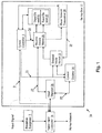
- Fig. 1 shows an embodiment of a combined home communications and broadcast signal receiving system 10.
- the system 10 includes a receiver 12, referred to hereinafter as a settop box.
- the settop box 12 includes a system controller 5 that receives user input in a known manner to selectively determine the type of data being output by the settop box 12 for display.
- the various control signals used in controlling settop box 12 operation are processed through the system controller 5.
- the settop box 12 includes a connector 14 for receiving at least two input signals via a single input, for example an F-connector coupled to coaxial cable.
- the system controller 5 communicates a mode determination signal 9 via the connector 14 which is used to selectively determine the type of signals processed by reception equipment 7 for receipt and display by settop box 12.
- Reception equipment 7 is able to receive at least one of (a) broadcast data signals, for example Digital Satellite Equipment Control (DiseqC) signals and (b) broadcast signals and digital home networking signals.
- Reception equipment 7 includes, for example, a satellite dish and other known associated electronic circuitry for receiving any of broadcast signals or digital home networking signals.
- the mode determination signal 9 reports back to the system controller 5 that reception equipment 7 receives broadcast data signals and in the second mode of operation, the mode determination signal 9 reports back to the system controller 5 that the reception equipment 7 to receive both broadcast data signals and digital home networking signals.
- the input signal at different times or in different modes, includes broadcast signals in the frequency range both above and below 950 MHz and the home networking signals in the frequency range below 950 MHz.
- the settop box 12 includes a band diplexer 16 which filters and separates the signal input into component signals that are above and below a threshold frequency, for example 950 MHz.
- the band diplexer 16 is coupled to a receive switch matrix 20 and a control diplexer 34.
- the receive switch matrix 20 in response to a receive control signal 24, selectively routes any signal passed via the diplexer 16 to a desired tuner (21, 22) for output.
- the control diplexer 34 is coupled to a transmit mode switch 32 and selectively filters the signal passed from the diplexer 16 according to signal type and frequency range.
- the transmit mode switch 32 is selectively configured to operate in a "transmit only" mode or a "transmit/receive" mode.
- the control diplexer 34 and transmit mode switch 32 advantageously enable transmission of a first type of signal (i.e. broadcast signal) and a second type of signal (home networking signal) wherein the frequency range associated with each of the first and second type at least partially overlaps.
- the transmit mode switch 32 is also coupled to the received matrix switch 20 for selective routing any signal passed via the transmit mode switch 32 to a desired tuner (21, 22) or a networking transceiver 28.
- the system 10 processes a first type of signal which is a broadcast signal (i.e. cable/satellite signal) and a second type of signal which is a home networking signal.
- a broadcast signal i.e. cable/satellite signal
- a second type of signal which is a home networking signal.
- the input signal received at connector 14 is separated by the band diplexer 16 into a first input signal 17 when the frequency is greater than 950 MHz.
- the first input signal 17 having a frequency greater than 950 MHz is provided to the receive switch matrix 20.
- the receive switch matrix 20 adaptively determines which of the one or more tuners 21, 22 that the first input signal 17 will be provided.
- the receive switch matrix 20 receives a receive control signal 24 from the system controller 5 that includes information for directing how the receive switch matrix 20 routes the first input signal 17 received from the diplexer 16.
- the receive control signal 24 causes the receive switch matrix 20 to selectively toggle between different outputs thus directing the received signal along the correct signal path.
- the signal path is determined in response to user-requested data, for example broadcast content type and channel.
- the portion of the input signal having a frequency below 950 MHz is separated and filtered by the diplexer 16 and provided as a second input signal 19 to the control diplexer 34.
- the mode determination signal 9 includes data identifying that the operational mode is the first mode (i.e. broadcast data signals only).
- the system controller 5 provides a control signal 31 to the control diplexer 34 to configure the control diplexer 34 to act as a pass-through for the second input signal 19 having a frequency below 950 MHz.
- the controls signal 31 is provided to the transmit mode switch 32 and configures the transmit mode switch 32 to operate in a transmit only mode.
- the second input signal 19 is a first type and is provided to the control diplexer 34.
- the control diplexer 34 filters and separates the second input signal 19 into a first type and a second type in response to the control signal 31 provided by the system controller 5 and based on the type of reception equipment 7 is provided.
- the first type of second input signal 19 is provided to the transmit mode switch 32.
- the transmit mode switch 32 in this first mode of operation, is directed to operate in a transmission mode in response to control signal 31 identifying the second input signal 19 is of a first type.
- the transmit mode switch 32 provides the first type of second input signal 19 to the receive switch matrix 20 which selectively determines the signal transmission path to a particular tuner/demodulator 21, 22.
- the operation of the receive switch matrix 20 is controlled by the receive control signal 24 which includes data that directs the receive switch matrix 20 to assign and provide a transmission path for the first type of second input signal 19.
- the receive switch matrix 20 in response to the receive control signal 24 selectively determines the path for signal transmission to the particular tuner/demodulator IC 21, 22.
- the switch matrix 20 is able to output broadcast signals having both low and high frequencies.
- the settop box 12 controls the reception equipment 7 to ensure it provides the type of signals the set top box wants to receive.
- the settop box 12 determines that it is not connected to a single wire mode (SWM Mode) enabled network (i.e. can only receive broadcast signals). This determination will be discussed hereinafter with respect to Figure 3 .
- the input signal received at connector 14 is a 22 KHz DiseqC signal, and the settop box configures itself to turn off (or initiate sleep mode) the networking transceiver 28.
- the system controller 5 When the system is operating in the first mode, the system controller 5 generates receive control signals 24 causing all received signals to be passed to one of the tuners 21, 22 based on channel selection information provided by the user.
- the set top box 12 will send out a control signal to tell the reception equipment 7 (satellite dish) to select the correct satellite and the correct polarity that allows 974 MHz to be present at the F connector input. That signal is provided to the diplexer 16, and because it is above 950 MHz, the diplexer filters the signal as the first input signal 17 which is provided to the receive switch matrix 20. Since the set top box 12 is looking for 974 MHz, the system controller 5 automatically sets the switch matrix 20 to connect the first input signal to the tuner requesting it (either 20 or 21).
- a user selects an HD channel and the set top box 12 determines that the desired channel is on the satellite at a location of 103 degrees and a downconverted frequency of 550 MHz, it sends a control signal out to the tell the reception equipment 7 to select the 103 satellite, and send down the correct polarity it needs.
- 250-750 MHz signals are provided to the F connector 14 and, because this portion of the input signal is below 950 MHz, the diplexer 16 filters the signal and provides the filtered signal as the second input signal 19.
- the system controller 5 determines that this second input signal is of a first type, the system controller 5, via control signals 31 configures the control diplexer 34 to act as a pass-through and transmit mode switch 32 to operate in a transmit only mode.
- the second input signal 19 having a frequency of 550 MHz is provided to the receive switch matrix 20 for connection to the appropriate tuner 20, 21.
- the system facilitates simultaneous transmission and output of a first input signal 17 having frequencies above the threshold frequency and a second input signal 19 of a second type having a frequency below the threshold frequency.
- the first input signal 17 may comprise a broadcast signal and the second input signal 19 may comprise a home networking signal.
- System controller 5 determines that the reception equipment 7 is able to operate in a SWM mode and is able to receive both broadcast and home networking signals.
- SWM mode the reception equipment receives all broadcast signals having frequencies between 250 MHz and 2150 MHz and automatically re-mixes any broadcast signals below the threshold frequency of 950 MHz to be over the 950 MHZ threshold.
- the band diplexer 16 separates the input signal received at connector 14 into the first input signal 17 of a first type and a second input signal 19 of a second type. Therefore, in this mode of operation, if one of the signals separated by the band diplexer 16 is below the threshold frequency (i.e. 950 MHz) the signal is a home networking signal having a frequency ranging between 400 MHz and 600 MHz.
- the system controller 5 determines that the reception equipment is able to operate in the second mode. In response to this determination, the system controller 5 generates the control signal 31 which may be a 2.3 MHz frequency shift keying (FSK) control signal associated with a home networking signal.
- the control signal 31 is provided to the control diplexer 34 which filters the second input signal 19 from the control signal 31 and identifies the second input signal as being of a second type (i.e. home networking signal).
- FSK frequency shift keying
- the system controller 5 directs the DUN transceiver 28 to generate a network control signal 29.
- the DHN transceiver 28 controls the transmit mode switch 32 depending on whether it is trying to receive (RX mode) or transmit (TX mode).
- the network control signal 29 is provided to the transmit mode switch 32 and configures the transmit mode switch 32 to operate in a bidirectional transmit/receive mode.
- transmit mode the DHN transceiver 28 sets the transmit mode switch 32 to TX mode and a home networking signal (MoCA signal) is transmitted from the DHN transceiver 28 through the transmit mode switch 32, control diplexer 34 and band diplexer 16 to an output via the connector 14.
- MoCA signal home networking signal
- the DHN transceiver 28 sets the transmit mode switch 32 to allow the second type of second input signals (home networking signals) separated by the control diplexer 34 to pass through the transmit mode switch 32.
- the transmit mode switch 32 provides the second type of second input signal 19 to the receive switch matrix 20.
- the switch matrix 20 in response to receive control signal 24, selectively connects the second type of input signal 19 (i.e., home networking signal having a frequency below 950 MHz) to a home network transceiver circuit 28.
- the settop box 12 after determining that the signal is a home networking signal, facilitates bidirectional communication between a plurality of settop boxes at a particular location, for example a user's home.
- the network transceiver 28 may provide the home networking signal to a further settop box based on routing data contained within the signal, for example.
- Other aspects of a settop box 12 for receiving broadcast signals as well as transmitting and receiving home networking communications, such as user interface and power supply are not shown but are easily understood as necessary for proper operation by one skilled in the art.
- the home networking communications system 10 used with settop box 12 shown in Fig. 1 is compliant with MoCA.
- the MoCA system utilizes a half duplex (i.e. only transmit or receive but not both simultaneously) protocol with variable multiple level symbol mapped orthogonal frequency division multiplexing (OFDM) modulation.
- MoCA may operate in any frequency range supported by transmission on a co-axial cable and the associated connected components such as amplifiers and signal splitters.
- the MoCA signal may be present in the spectral vicinity of the broadcast signal.
- potential adverse signal conditions created due to the presence of a high signal power level MoCA signal and a weaker signal power level broadcast signal typically require that a frequency spectrum guard band exist between the home networking service and the broadcast signals.
- the home networking signal being a MoCA-compliant signal is provided for purposes of example only and the system may demodulate any home networking protocol supported by a shared signal delivery medium.
- the system is able to adaptively distinguish between two different types of signals without additional costly circuitry even when the frequencies of the signals overlap one another by diplexing and switching during demodulation. It is important to note that the present disclosure may be used with other home networking protocols that operate on a shared signal delivery medium.
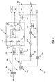
- Fig. 2 is a circuit diagram of a combined home communications and broadcast signal receiving system 200.
- System 200 includes a plurality of circuits used in conventional settop boxes and conditions these circuits to adaptively filter and route two different types of input signals that are transmitted simultaneously as part of a single signal delivery mechanism via an input 202.
- the circuitry shown herein enables the settop box to reduce the complexity of the receiver resulting in the settop box being produced at a lower cost but improving operational performance.
- the system 200 may be implemented as part of a satellite settop box capable of receiving signals having a wide range of frequencies whereby the signals contain audio/video content from one or more satellite services using a single coaxial cable input 202.
- the system 200 includes a diplexer 204 for separating and filtering the input signals according to their respective frequencies.
- the diplexer 204 is coupled via a first balanced to unbalanced coupler, often referred to as a balun, 208 to a routing circuit 212 for routing the separated signals to the proper output terminals, for example to a tuner or a networking transceiver.
- the routing circuit 212 includes a first input 210 and a second input 220.
- the first input 210 is coupled to a first input variable gain amplifier 214 which sets the front end gain and noise figures and which attenuates the signal in the presence of higher input powers.
- the second input 220 is coupled to a second input variable gain amplifier 214 which sets the front end gain and noise figures and which attenuates the signal in the presence of higher input powers.
- the first and second inputs 210, 220 are connected to a cross switch 216 that enables any input 210, 220 to independently access any output device which includes any of first tuner 246, second tuner 248 and networking transceiver 250.
- the routing circuit 212 further includes output buffer amplifiers 218, 224, and 226 which operate in a known manner and are coupled between the cross switch 216 and the respective outputs, 246, 248 and 250. Additionally, a balanced to unbalanced coupler 251 may be coupled between the output buffer amplifier 251 and the network transceiver 250.
- the system 200 is also able to engage in bidirectional communication with other similar settop boxes via a home networking protocol.
- the network transceiver 250 of system 200 includes a networking receiver 254 which receives a DHN signal 256, for example a MoCA home networking signal.
- the DHN signal 256 has a frequency associated therewith that overlaps at least partially, a frequency of one of the input signals received via input 202.
- the system includes additional circuitry that enables processing of the DHN signal 256 received via the networking receiver 254.
- the system 200 further includes a coupler 242 connected to a first MoCA transmit filter which filters out the harmonics from the networking receiver 254.
- a MoCA amplifier 238 is connected to the first MoCA transmit filter 240 and provides the final output gain for the transmitted DHN signal 256.
- a second MoCA transmit filter 236 is connected to the MOCHA amplifier 238 which filters out any remaining harmonics from the receiver 254 and any harmonics generated by the amplifier 238.
- the DHN signal 256 is provided to a transmission/receiving (TX/RX) switch 232 and to the routing circuit 212. Once received by the routing circuit 212, the DHN signal is provided to the networking transceiver 252 for communication to a further settop box on the network. Additionally, once received, DHN signal 256 may be provided to a system controller (not shown) for processing the DHN signal into audio and video data.
- the system controller can also package data from an incoming satellite signal or acquire data from a storage drive and send the data to the DHN transceiver 250 for transmission to other external DHN-equipped devices on the home network (i.e., connected via coaxial cable).
- the DHN data may be selectively transmitted to other set top boxes with integrated DHN, or non-DHN equipped boxes using a converter such as an Ethernet-coaxial cable-bridge (ECB) that allows a person to connect the DHN signal to a personal computer through Ethernet whereby the user can selectively view digital streaming audio-video data, for example a downloaded movie from a service provider using the settop box.
- EBC Ethernet-coaxial cable-bridge
- the settop box shown in Figure 2 is configured to operate in a first mode whereby the system receives broadcast signals and a second mode whereby the system receives broadcast signals and digital home networking signals.
- the determination of the mode of operation may be performed in accordance with the mechanisms described in Figures 3-5 .
- the input signal 202 from a single coaxial cable is provided to a diplexer 204.
- the diplexer 204 filters and separates the incoming signal into a portion of spectrum from 950 MHz to 2150 MHz, known as the L-band 206, and a portion of spectrum from 250 MHz to 750 MHz, known as the B band 228.
- the diplexer 204 operates with 950 to 2150 MHz (L-Band) satellite signals 206 being provided to a first input 210 of the routing circuit 212 and distributed to one or more of a first set of satellite tuner/demodulator circuits 246, 248 as needed.
- the system 200 further includes a control diplexer 230 coupled between the diplexer 204 and the transmit/receive switch 232.
- the control diplexer 230 filters control signals between 2.3 MHz, for example MoCA control signal generated via a SWM module and satellite B-band signals operating above 500 MHz.
- Satellite signals filtered by the diplexer 204 that are in the 250-750 MHz region (B-band) are routed to the second input 220 via the control diplexer 230 and the transmit/receive switch 232.
- the TX/RX switch 232 is defaulted to allow only B-Band signals 228 to pass through because this is the first mode of operation.
- the routing circuit 212 distributes the B-Band signal 228 to one or more a second set of the satellite tuner/demodulators 246, 248. It is important to note that the first set and second set of satellite tuner/demodulators may be the same.
- the first mode of operation is DiseqC mode or non-DHN mode. Non-DHN mode is present when the incoming signals are delivered from multiple sources over a common co-axial cable and no single wire multiplex signaling mode is present.
- the second mode of operation is DHN mode whereby the system is able to receive both broadcast signals across the entire spectral range (250 MHz - 2150 MHz) and a DHN signal having a frequency that partially overlaps a portion of the broadcast signal frequency range (500 MHz and 600 MHz).
- a SWM module (not shown) provides an FSK control signal which is filtered by a SWM filter 244.
- the SWM filter is a narrow bandpass filter and filters signals having a frequency below 2.3 MHz.
- DHN signal 256 is received by networking receiver 254.
- the networking transceiver 250 (or alternatively, the SWM module) configures the TX/RX switch 232 to toggle between a first position enabling passage of B-band satellite signals and a second position enabling passage of the DHN signal 256.
- the TX/RX switch 232 needed for DHN signal transmission is placed in front of the routing IC 212 to allow a tap-in point for the DHN transmission path. In the second position, the TX/RX switch passes the DHN signal 256 to the second input 220 of the routing circuit 212.
- the cross switch 216 Upon receipt of the DHN signal 256 by the routing circuit 212, the cross switch 216 automatically associates the second input 220 with the output associated with the DHN transceiver 250 and DHN signal 256 is provided to the transmitter 252 of the networking transceiver 250.
- the cross switch 216 selectively routes all of the input signals, whether they are broadcast signals or DHN signals, to the proper output devices.
- the L-Band signal 228 is routed by the switch to any of the tuners 246 and/or 248. Additionally, the B-Band signals routed via the second input 220 are also routed by the cross switch 216 to any of the tuners 246 or 248, as needed.
- the cross switch will prevent access to the networking transceiver 250 and the TX/RX switch 232 is locked in receive mode allowing B-Band signals to pass through to the second input 220.
- all broadcast signals are above the threshold frequency of 950 MHz and are provided to the first input 210.
- Cross switch 216 selectively toggles between the tuners 246 and 248, as needed and the satellite signals are provided thereto. Additionally, in the second mode of operation, the cross switch 216 automatically routes signals received at the second input 220 to the network transceiver 250 because there are no B-band signals filtered by diplexer 204.
- the TX/RX switch 232 is selectively toggled between the transmit mode and receive mode as needed enabling transmission and reception of home networking signals.
- the mode of operation is set prior to system operation in the manner discussed below with respect to Figures 3A-3C. Operational modes may be changed during a new installation or during upgrade of an existing installation.
- the system advantageously makes use of the second input on a routing circuit 212 for reception of either the B-band signal or the DHN signal 256 when present.
- the TX/RX switch 232 further provides a transmission for DHN signal 256 for output via the connector 202.
- This second mode of operation providing a transmission path for the DHN signal 256 is advantageously employed when the incoming signals are delivered from multiple sources over a common co-axial cable using DiseqC signaling mode, for example.
- the architecture of the system 200 advantageously reduces the complexity of the device by eliminating two switches, a received signal amplifier and a signal attenuator while also preserving the benefits of the diplexed arrangement for operation in non-DHN modes.
- the arrangement may also lower the additional filtering and signal separation necessary for proper operation of the satellite broadcast receiver circuits for both L- band and B-band.
- the system beneficially uses a diplexer 204 to split B-band and L-band signals and enables use of the inputs 210 and 220 to route desired signals to the tuners 246 and 248. Without this diplexer 204, to make use of the two inputs of 212, a system would need two switches for satellite signals. The first switch would take the place of the diplexer 204.
- Figures 3-5 represent exemplary mechanism for controlling the switch operation with the routing circuit.
- the control mechanism enables the system to maximize the availability of the inputs for use by a plurality of different types of digital data signals even when two of the signals routed through the switch have overlapping frequencies.
- a control processor parses configuration data in order to condition switch operation.
- the term processor is hardware that is conditioned to operate by a set of logical instructions encoded thereon directing the operation of other circuits within the system.
- the configuration data used by the system may include at least one of predetermined configuration data including information that conditions the system to provide a first signal type within a first frequency range to a first input of the routing circuit.
- Configuration data further includes information that conditions the system to provide a first signal type within a different frequency range to a second input and a second signal type within the second frequency range to the second input. This advantageously enables the system to use two existing inputs to provide two different signal types for demodulation even when there is an overlapping frequency range associated therewith.
- Figures 3-5 describe exemplary control mechanisms and the configuration data used to condition system operation.
- Figure 3 is a block diagram of a system that employs predetermined configuration data for use in controlling the switch in the routing circuit.
- an installer sets the configuration data to include information that the settop box is to operate in a SWM mode.
- the configuration data is provided by a system controller (not shown) as a control signal 320 to a TX/RX switch 315 and routing switch 310 which uses the information within the control signal 320 to direct the path of transmission to the desired demodulator (i.e. tuner or networking transceiver).
- the desired demodulator i.e. tuner or networking transceiver.
- the settop box is able to receive a plurality of input signals, including satellite and DHN signals, at a common input 302.
- the satellite signals received encompass signals having frequencies ranging between 250 MHz and 2150 MHz.
- the SWM module remixes the signals, as needed, such that all satellite signals are above the 950 MHz threshold frequency.
- This signal is filtered and separated by diplexer 305 into a first input signal of a first type (broadcast signal) having a frequency greater than a threshold frequency and a second input signal of either a first type or second type (DHN signal) having a frequency below the threshold frequency.
- the first input signal of the first type may be a cable/satellite signal in the L-Band frequency range that is provided, as discussed above with respect to Figs. 1 and 2 , to a first input 307 on the routing circuit 300.
- the control signal 320 is provided to the TX/RX switch 315. Based on the information in the control signal 320 identifying the second input signal being the second type (i.e. DHN signal), the TX/RX switch IC 315 is configured to operate in a TX/RX mode enabling transmission of MoCA DHN signal to a second input 309 of the routing circuit 300.
- the control signal 320 is also received by the routing switch 310 which enables the routing circuit 300 of the settop box to route the incoming second input signal to be provided to a DHN receiver 330 for demodulation.
- the control signal 320 may include information directing the settop box to operate in traditional DiseqC mode whereby the incoming signal is diplexed by diplexer 305 into L-Band and B-Band signals.
- the L-Band signal is received at the first input 307.
- the information in the control signal 320 provided to the TX/RX switch 315 configures the switch to operate in a RX mode and receives the B-Band from diplexer 305.
- the TX/RX switch 315 provides the B-Band signal at the second input 309.
- the control signal 320 further configures the routing switch 310 to provide the L-Band signal to a first tuner 332 and the B-Band signal to a second tuner 334.
- control signal 320 may direct the any of the L-Band and B-Band signals to at least one of any of the tuners 332 or 334, the same tuner, and a further demodulator circuit (not shown).
- Figure 4 illustrates another control mechanism that may be implemented by the system to selectively determine the signal transmission path for a plurality of different type of input signals.
- the control mechanism enables the adaptive switching between operation modes such that the settop box can switch modes of operation at a given time based on the content of the input signal received.
- a mode Controller 340 is provided and employs a "smart" algorithm for automatically detecting the composition of the signal.
- the mode controller 440 generates a detection signal 445 which polls the contents of the input signal being received at input connector 402. This may be performed, for example, by polling the coaxial cable for presence of a SWM-equipped outdoor unit present at a particular location.
- the mode controller 440 determines that the settop box should operate in DiseqC mode.
- the diplexer 405 filters and separates the input signal into a first input signal of a first type (L-Band satellite signal having a frequency ranging between 950 MHz and 2150 MHz) and a second input signal of a first type (B-Band satellite signal having a frequency ranging between 250 MHz and 950 MHz).
- the mode controller 440 configures the routing switch 410 for passing the L-Band and B-Band signals to respective tuners 432, 434 for demodulation.
- the L-Band signal is provided at the first input 407 of the routing circuit 400 and the B-Band signal is provided at the second input 409 of the routing circuit.
- the mode controller 440 configures the routing switch 410 to toggle between the first tuner 432 and the second tuner 434 to provide a signal transmission path to the desired tuner for demodulation. In this mode, the settop box would not implement the DHN mode which remains shut down.
- the mode controller 440 if the result of the test performed by the mode controller 440 returns a true value via detection signal 445, the mode controller 440 generates the control signal 420 which is provided to the TX/RX switch 415.
- Control signal 420 configures the TX/RX switch 415 to operate in a transmit/receive mode for receiving a second input signal of a second type (i.e. a DHN signal having a frequency below 950 MHz and between 500 MHz - 600 MHz).
- the DHN signal is provided to the routing circuit 400 via the second input 409.
- the mode controller 440 configures the routing switch 410 to route the DHN signal to the home network transceiver 430 for demodulation. Also, in this mode, the mode controller 440 configures the routing switch to route the L-Band signal received via the first input 407 of the routing circuit 400 to one of the tuners 432 or 434 for demodulation.
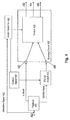
- FIG. 5 is yet another embodiment of a control mechanism that may be implemented by the system.
- This control mechanism utilizes a power controller 560 connected to the routing circuit 500 for detecting an amount of power of the second input signal in order to configure the operation of a TX/RX switch 515.
- the power controller 560 being shown as a separate and distinct circuit is provided for exemplary purposes only and one skilled in the art recognizes that the features and operation of the power controller 560 may be incorporated as part of a system controller circuit as discussed in Figure 1 .
- the switch 510 includes an AGC (automatic gain control) Detector 562 for detecting the amount of power present at signals within a first frequency range, i.e. 250 MHz and 950 MHz at the first input 507 and second input 509 of the routing circuit 500.
- AGC automatic gain control
- the switch 510 further includes a narrow band AGC detector 564 for detecting an amount of power present at signals within a narrower frequency range, i.e. 500 MHz and 600 MHz at the first input 507 and second input 509.
- the power controller 560 senses an amount of power present at the input connector 502.
- the input signal is filtered and separated by diplexer 505 into a first input signal having a frequency ranging between 950 MHz and 2150 MHz (L-Band signal) and a second input signal having a frequency ranging between 250 MHz and 950 MHz (i.e. B-Band or DHN signal).
- the narrow band AGC detector 564 Upon sensing that power is present at the second input 509, the narrow band AGC detector 564 senses the presence of power at frequencies outside of the DHN band (500-600 MHz). These detectors measure, or detect, all of the power present at their respective inputs, but because of the diplexer 505 filters and separates the original input signal, the detection by the detectors 562, 564 at the second input 509 determines if any power is present below 950 MHz.
- a second AGC detection estimate is available using AGC detectors inside the tuners 532, 534 (not shown). Each tuner has an AGC detector with a pickoff point that is downstream from the narrower band-limiting filters needed by the tuner to tune a particular frequency.
- the AGC detectors in the tuners sense the power available in that particular narrow bandwidth. For example, if a tuner is tuned receive a satellite signal at 1100 MHz, the AGC detector is going to see power within a frequency ranging between 1090 MHz and 1110 MHz, depending on how narrow the tuner filters are set.
- the settop box In response to a report, or indication, that power is present outside the DHN frequency range, the settop box will default to operate in DiseqC mode thus facilitating passage of L-Band signal to the first input 507 and B-Band signal to the second input 509 of the routing circuit 500.
- the power controller 560 directs the routing switch 510 to route the L-Band and B-Band signals, received via the first and second inputs 507, 509, to the desired tuner/demodulator 532, 534.
- power controller 560 In response to a report, or indication, that power is not present at signals outside of the DHN band, but the narrow-band AGC detector 564 senses power within the DHN band frequency range, then power controller 560 generates and transmits a SWM. polling signal which is sent out to verify the presence of a SWM so that DHN-mode can be enabled.
- the SWM polling signal is provided by the power controller 560 to the external reception equipment (not shown) via the connector 502.
- the power controller 560 generates and receives communication messages to and from the external SWM device (SWM's communication mode is a bidirectional FSK at 2.3 MHz).
- the controller transmits FSK polling messages that go out on the coaxial cable and if there is a SWM "master" on the coaxial cable (like a dish), it will respond and begin sending the set top “registration” information which is used to configure the operation of the switch 510 within the routing circuit.
- the satellite signals are remixed as necessary such that the signals have frequencies greater than the threshold frequency of 950 MHz.
- the satellite signals are separated by diplexer 505 and provided at the first input 507 of the routing circuit 500.
- the routing switch 510 passes these signals to at least one of the tuners 532, 534 for demodulation.
- the TX/RX switch 515 is configured, in response to a configuration signal provided by the power controller 560, to operate in a transmit/receive mode enabling DHN signal transmission and the DHN signal is provided at the second input 509 of the routing circuit.
- the power controller 560 configures the routing switch 510 to route the DHN signal to a networking transceiver 530.
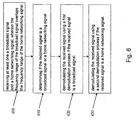
- the settop box receives at least one of a broadcast signal and a home networking signal at a common input wherein the frequency range of the broadcast signal overlaps the frequency range of the home networking signal.
- a broadcast signal is a digital data signal used for transmitting audio/visual or other data by a cable or satellite provider, for example.
- the system adaptively determines, in step 610, if the received signal is a broadcast signal or a home networking signal. This determination is made by diplexing the received signal into components that are above and below a threshold frequency, for example 950 MHz.
- any signal separated by the diplexer that is above the threshold frequency is determined to be a broadcast signal and is provided to a first input of a routing circuit of the settop box which assigns the broadcast signal to a particular signal transmission path.
- the broadcast signal is demodulated using a first demodulation process.
- the first demodulation process may include, for example, tuning to a frequency in response to user selection of a particular content channel.
- the broadcast signal is provided to a tuner for demodulation and output to a display device in a known manner.
- the home networking signal is provided for demodulation using a second demodulation process in step 630.
- the second demodulation process may include, for example, processing of a digital home networking signal in a known manner.
- the home networking signal is provided to a networking transceiver for demodulation and communication to further settop boxes on the network.
- This method makes use of the two inputs of the routing circuit for receiving three different types of input signals where only two were previously able to be received.
- the settop box operating in according with the above method is structurally less complex and costs less to produce.
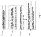
- the settop box receives a signal at common signal input.
- the received input signal spans a first frequency range and a second frequency range.
- the received signal is separated according to frequency in step 710.
- a portion of the received signal in the first frequency range is provided as a first input signal and a portion of the received signal in the second frequency range is provided as a second input signal.
- the first input signal in the first frequency range is a first signal type.
- a diplexer separates the signals based on a threshold frequency and assigns the signal having the frequency above the threshold value as the first input signal type (i.e. L-Band).
- step 720 it is determined if the received portion of signal in the second frequency range is of the first signal type or a second signal type. This determination may be made, as discussed in accordance with the description of Figure 6 whereby the system senses the power associated with the signal to determine the mode of operation. For example, the second input signal in the second frequency range is polled to determine if power is present outside a particular frequency range (i.e. below 500 MHz and above 600 MHz) and within a particular frequency range (i.e. between 500 MHz and 600 MHz). If power is sensed, or detected, in at least one of a frequency range above and below the particular frequency range, the second input signal is determined to be of the first type (i.e. a B-Band signal).
- a particular frequency range i.e. below 500 MHz and above 600 MHz
- a particular frequency range i.e. between 500 MHz and 600 MHz.
- the second input signal is determined to be of a second signal type, i.e. a DHN signal.
- the second portion of the frequency range is provided for demodulation by a demodulator capable of demodulating the first signal type if the received portion of the signal in the second frequency range is determined to be the first signal type.
- the routing circuit provides a second portion of the frequency range that is of a second type to a demodulator capable of demodulating the second signal type if the received portion of the signal in the second frequency range is determined to be the second signal type. While the operation discussed in Figure 7 describes using the mechanism set forth in Figure 5 , one skilled in the art can readily adapt the control mechanism to be in accordance with any of Figures 3 and/or 4.
- the system is capable of receiving broadcast type signals, such as signals delivered over a satellite network, as well as home network signals, such as those delivered over MoCA.
- the system may operate in one of two modes.
- the receiver first determines, through inputs from the user or through a determination made by a microprocessor in the settop box, if the current operation is not a single wire multiplex mode that will utilize the B-band frequency range. If the settop box determines that B-band is used, then home networking operations are disabled and the network switch shown in Figs. 1 and 2 is connected so that the input signal from the input diplexer is connected through to a satellite tuner/ demodulator circuit.
- the settop box determines that B band is not used, then home networking operations are enabled and the network switch shown in Figs. 1 and 2 is connected so that the input signal from the input diplexer is connected through to the home networking transceiver. It is important to note that the user may also control whether home networking operations are available even if B-band broadcast signals are not used. Further, the determination of operation for B-band use may be made at initial settop box configuration or may be continually updated. For instance, the availability of home networking operation may be determined each time a new program or channel is selected by a user. In this manner, home networking operation may be only interrupted rather than completely eliminated from use based on the presence of B band signals in some instances.
Landscapes
- Engineering & Computer Science (AREA)
- Signal Processing (AREA)
- Multimedia (AREA)
- Computer Networks & Wireless Communication (AREA)
- Automation & Control Theory (AREA)
- Circuits Of Receivers In General (AREA)
- Two-Way Televisions, Distribution Of Moving Picture Or The Like (AREA)
- Transceivers (AREA)
- Selective Calling Equipment (AREA)
- Small-Scale Networks (AREA)
Claims (8)
- Verfahren, das die folgenden Schritte umfasst:Empfangen (700) eines Signals (202), wobei das Signal von einem Rundfunktyp und/oder von einem Typ einer digitalen Heimvernetzung ist;Trennen (204, 710) des Empfangssignals (202) in einen ersten Anteil (206) des Empfangssignals in einem ersten Frequenzbereich und in einen zweiten Anteil (228) des Empfangssignals in einem zweiten Frequenzbereich, wobei der erste Anteil des Empfangssignals in dem ersten Frequenzbereich von dem Rundfunktyp ist;Bestimmen (610, 720), ob der zweite Anteil (228) des Empfangssignals von dem Rundfunktyp oder von dem Typ einer digitalen Heimvernetzung ist, wobei der Schritt des Bestimmens dadurch gekennzeichnet ist, dass er umfasst:- Detektieren einer Signalleistung (560) in dem zweiten Anteil des Empfangssignals,- Detektieren einer Signalleistung (560) außerhalb eines schmaleren Frequenzbereichs, das ein Band einer digitalen Heimvernetzung ist,- Bestimmen, dass der zweite Anteil des Empfangssignals von dem Rundfunktyp ist, falls Signalleistung außerhalb des schmaleren Frequenzbereichs detektiert wird, und- Bestimmen, dass der zweite Anteil des Empfangssignals von dem Typ eines digitalen Heimnetzes ist, falls Signalleistung in dem zweiten Anteil des Empfangssignals detektiert wird und keine Signalleistung außerhalb des schmaleren Frequenzbereichs detektiert wird; undDemodulieren (620) des zweiten Anteils des Empfangssignals unter Verwendung eines Tuners/Demodulators (246, 248), falls bestimmt wird, dass der zweite Anteil des Empfangssignals von dem Rundfunktyp ist.
- Verfahren nach Anspruch 1, das ferner die folgenden Schritte umfasst:- Aussenden eines Abfragesignals zum Ermitteln der Anwesenheit eines Eindrahtbetriebsart-Moduls, so dass eine Betriebsart eines digitalen Heimnetzes freigegeben werden kann, falls bestimmt wird, dass der zweite Anteil des Empfangssignals von dem Typ einer digitalen Heimvernetzung ist;- Freigeben der Betriebsart eines digitalen Heimnetzes, falls die Anwesenheit des Eindrahtbetriebsart-Moduls ermittelt wird,- Demodulieren (630) des zweiten Anteils des Empfangssignals unter Verwendung eines Heimvernetzungs-Transceivers (28, 250), falls die Betriebsart eines digitalen Heimnetzes freigegeben ist.
- Verfahren nach Anspruch 2, das ferner die folgenden Schritte umfasst:Konditionieren eines Schalters (32, 232) zum Übergeben des Signals von dem Rundfunktyp an einen Eingang einer Routing-Schaltung (20, 212) zur Demodulation unter Verwendung des Tuners/Demodulators (246, 248), falls bestimmt wird, dass der zweite Anteil des Empfangssignals von dem Rundfunktyp ist; undKonditionieren des Schalters (32, 232) zum Übergeben des Signals von dem Typ einer digitalen Heimvernetzung an den Eingang der Routing-Schaltung (20, 212) zur Demodulation unter Verwendung des Heimvernetzungs-Transceivers (28, 250), falls bestimmt wird, dass der zweite Anteil des Empfangssignals von dem Typ einer digitalen Heimvernetzung ist.
- Verfahren nach Anspruch 2, wobei der Schritt des Bestimmens ferner umfasst:- Empfangen von Registrierungsdaten (9) von dem Eindrahtbetriebsart-Modul in Ansprechen auf das Abfragesignal; und- Identifizieren einer Betriebsart zum Empfang des Signals von dem Rundfunktyp in Ansprechen auf die empfangenen Registrierungsdaten.
- Vorrichtung, die umfasst:einen Diplexer (16, 204, 305, 405, 505), der ein Signal empfängt, das von einem Rundfunktyp und/oder von einem Typ einer digitalen Heimvernetzung ist, und der das Empfangssignal filtert, um einen ersten Anteil (17) des Empfangssignals in einem ersten Frequenzbereich und einen zweiten Anteil (19) des Empfangssignals in einem zweiten Frequenzbereich zu erzeugen, wobei der erste Anteil (17) des Empfangssignals in dem ersten Frequenzbereich von dem Rundfunktyp ist;eine Schaltschaltung (20), die mit dem Diplexer (16) gekoppelt ist, die den zweiten Anteil des Empfangssignals in dem zweiten Frequenzbereich empfängt;einen Controller (5), der mit dem Ausgang der Schaltschaltung (20) gekoppelt ist, der bestimmt, ob der zweite Anteil des Empfangssignals in dem zweiten Frequenzbereich von dem Rundfunktyp oder von dem Typ einer digitalen Heimvernetzung ist, wobei der Controller dadurch gekennzeichnet ist, dass er dafür konfiguriert ist (560), eine Signalleistung in dem zweiten Anteil des Empfangssignals zu detektieren, zu detektieren, dass eine Signalleistung außerhalb eines schmaleren Frequenzbereichs ein Band einer digitalen Heimvernetzung ist, zu bestimmen, dass der zweite Anteil des Empfangssignals von dem Rundfunktyp ist, falls Signalleistung außerhalb des schmaleren Frequenzbereichs detektiert wird, und zu bestimmen, dass der zweite Anteil des Empfangssignals von dem Typ eines digitalen Heimnetzes ist, falls Signalleistung in dem zweiten Anteil des Empfangssignals detektiert wird und keine Signalleistung außerhalb des schmaleren Frequenzbereichs detektiert wird; undmindestens einen Tuner/Demodulator (21, 22), der mit der Schaltschaltung (20) gekoppelt ist, der den zweiten Anteil des Empfangssignals in dem zweiten Frequenzbereich zur Demodulation empfängt, falls bestimmt worden ist, dass der zweite Anteil des Empfangssignals in dem zweiten Frequenzbereich von dem Rundfunktyp ist.
- Vorrichtung nach Anspruch 5, die zusätzlich dafür konfiguriert ist, ein Abfragesignal bereitzustellen, um zu bestimmen, ob ein Eindrahtbetriebsart-Modul vorhanden ist, um das Signal von dem Typ einer digitalen Heimvernetzung zu empfangen, falls bestimmt worden ist, dass der zweite Anteil des Empfangssignals in dem zweiten Frequenzbereich von dem Typ eines digitalen Heimnetzes ist, wobei die Vorrichtung ferner umfasst:einen Heimvernetzungs-Transceiver (28, 250) zum Demodulieren des Signals von dem Typ einer digitalen Heimvernetzung.
- Vorrichtung nach Anspruch 6, wobei der Controller (5) ferner dafür konfiguriert ist, in Ansprechen auf das Abfragesignal Registrierungsdaten von dem Eindrahtbetriebsart-Modul zu empfangen und in Ansprechen auf die empfangenen Konfigurationsdaten eine Betriebsart zum Empfangen des Signals von dem Rundfunktyp zu identifizieren.
- Vorrichtung nach Anspruch 6, wobei der Controller (5) die Schaltschaltung (20) dafür konfiguriert, den zweiten Anteil des Empfangssignals für den Heimvernetzungs-Transceiver (28, 250) bereitzustellen.
Applications Claiming Priority (2)
| Application Number | Priority Date | Filing Date | Title |
|---|---|---|---|
| US20639209P | 2009-01-30 | 2009-01-30 | |
| PCT/US2009/068487 WO2010087913A2 (en) | 2009-01-30 | 2009-12-17 | System and method for combined home network communications and broadcast reception in a settop box |
Publications (3)
| Publication Number | Publication Date |
|---|---|
| EP2384577A2 EP2384577A2 (de) | 2011-11-09 |
| EP2384577A4 EP2384577A4 (de) | 2014-06-18 |
| EP2384577B1 true EP2384577B1 (de) | 2016-02-24 |
Family
ID=42396248
Family Applications (1)
| Application Number | Title | Priority Date | Filing Date |
|---|---|---|---|
| EP09839470.3A Active EP2384577B1 (de) | 2009-01-30 | 2009-12-17 | System und verfahren für kombinierte heimnetzwerkkommunikation und rundfunkempfang in einer settop-box |
Country Status (7)
| Country | Link |
|---|---|
| US (1) | US8463228B2 (de) |
| EP (1) | EP2384577B1 (de) |
| JP (2) | JP2012516634A (de) |
| KR (1) | KR101668852B1 (de) |
| CN (1) | CN102301731B (de) |
| BR (1) | BRPI0923944B1 (de) |
| WO (1) | WO2010087913A2 (de) |
Families Citing this family (19)
| Publication number | Priority date | Publication date | Assignee | Title |
|---|---|---|---|---|
| KR101557664B1 (ko) * | 2009-10-22 | 2015-10-06 | 삼성전자 주식회사 | 데이터통신장치 및 그 데이터통신방법 |
| CN102812720B (zh) * | 2010-01-15 | 2016-04-20 | 汤姆森特许公司 | 数字家庭联网设备中节能的系统和方法 |
| US9148295B2 (en) * | 2010-02-09 | 2015-09-29 | Broadcom Corporation | Cable set-top box with integrated cable tuner and MOCA support |
| US8625586B2 (en) * | 2010-12-31 | 2014-01-07 | Stmicroelectronics International N.V. | Generic bus de-multiplexer/port expander with inherent bus signals as selectors |
| BR112014003231A2 (pt) * | 2011-08-12 | 2017-03-14 | Entropic Communications Inc | método para selecionar bandas de frequência em dispositivo de rede para várias redes nativas |
| US8813135B2 (en) * | 2011-11-21 | 2014-08-19 | Maxlinear, Inc. | Method and system for providing a home cable network |
| US9213092B2 (en) * | 2012-06-12 | 2015-12-15 | Tyco Fire & Security Gmbh | Systems and methods for detecting a change in position of an object |
| JP2015528232A (ja) * | 2012-06-18 | 2015-09-24 | トムソン ライセンシングThomson Licensing | ダイプレクサ回路に電力または制御信号を挿入するための装置および方法 |
| BR112014031628A2 (pt) * | 2012-06-18 | 2017-08-01 | Thomson Licensing | aparelho e método para filtrar sinais em um receptor |
| JP5988863B2 (ja) * | 2012-12-27 | 2016-09-07 | パナソニック株式会社 | 受信装置及び復調方法 |
| US9635310B2 (en) * | 2013-05-05 | 2017-04-25 | Maxlinear, Inc. | Band translation with protection of in-home networks |
| CN105830396A (zh) * | 2013-12-18 | 2016-08-03 | 汤姆逊许可公司 | 用于机顶盒的前端多工器拓扑 |
| US9413327B2 (en) | 2014-04-21 | 2016-08-09 | Thomson Licensing | Apparatus and method for filtering a signal |
| CN104994322B (zh) * | 2015-06-30 | 2018-09-04 | 深圳市九洲电器有限公司 | 一种电视信号处理的装置和电视机顶盒 |
| US10182403B2 (en) | 2015-09-30 | 2019-01-15 | Skyworks Solutions, Inc. | Diplexed coupler for carrier aggregation |
| JP7173472B2 (ja) * | 2017-10-27 | 2022-11-16 | ソニーセミコンダクタソリューションズ株式会社 | チューナ装置 |
| KR20210087432A (ko) * | 2018-08-02 | 2021-07-12 | 베스텔 일렉트로닉 사나이 베 티카레트 에이에스 | 모니터링 장치, 전자 디바이스, 단일 케이블 위성 시스템, 및 모니터링 방법 |
| WO2022164433A1 (en) * | 2021-01-28 | 2022-08-04 | ARRIS Enterprises, LLC | System and method for improved determination of universal low noise block satellite interface type |
| KR20230151932A (ko) | 2022-04-26 | 2023-11-02 | 주식회사 케이티 | 통합 단말 장치 |
Family Cites Families (27)
| Publication number | Priority date | Publication date | Assignee | Title |
|---|---|---|---|---|
| JPH0787415A (ja) * | 1993-09-09 | 1995-03-31 | Funai Electric Co Ltd | 受信機の受信チャンネル自動設定方法 |
| KR100322050B1 (ko) * | 1999-07-12 | 2002-02-06 | 윤종용 | 쌍방향 멀티미디어 서비스를 위한 홈 네트워크 시스템 |
| JP3540242B2 (ja) * | 2000-03-30 | 2004-07-07 | 松下電器産業株式会社 | 多方式対応受信装置 |
| US20010037512A1 (en) | 2000-04-06 | 2001-11-01 | Flickner Andrew Kent | Signal interface for a bi-directional communication device |
| JP2002237903A (ja) * | 2001-02-08 | 2002-08-23 | My Tv Kk | Catv装置およびcatv網内線電話システム |
| US7310355B1 (en) | 2002-08-23 | 2007-12-18 | Digeo, Inc. | Apparatus and method for powering a network device |
| JP4181392B2 (ja) * | 2002-12-02 | 2008-11-12 | 日本放送協会 | 放送波受信と無線lanまたは無線アクセスによるインターネット接続サービスの送受信とを両立させたアンテナ装置 |
| EP1602208B1 (de) * | 2003-03-03 | 2006-09-06 | Matsushita Electric Industrial Co., Ltd. | Mobiles endgerät mit funktionen für rundfunk- und netzwerkprogrammempfang und verfahren zur steuerung des programmempfanges |
| US7343140B2 (en) * | 2003-04-10 | 2008-03-11 | Intel Corporation | Tuner |
| US7623580B2 (en) | 2003-06-30 | 2009-11-24 | Nxp B.V. | Simultaneous multiple channel receiver |
| KR100565942B1 (ko) * | 2003-08-13 | 2006-03-30 | 한국전자통신연구원 | 이더넷 기반의 방송 및 통신 융합 시스템 및 그 방법 |
| JP2005136905A (ja) * | 2003-10-31 | 2005-05-26 | Maspro Denkoh Corp | インターホンシステム及び信号中継装置 |
| US7231227B2 (en) * | 2004-08-30 | 2007-06-12 | Kyocera Corporation | Systems and methods for blind source separation of wireless communication signals |
| GB0504500D0 (en) * | 2005-03-04 | 2005-04-13 | Guided Ultrasonics Ltd | Signal processing arrangement |
| JP4712416B2 (ja) * | 2005-03-25 | 2011-06-29 | パナソニック株式会社 | セットトップボックスのフロントエンド装置及びその構築方法 |
| NO324318B1 (no) * | 2005-04-29 | 2007-09-24 | Tandberg Telecom As | Fremgangsmate og anordning for stoydeteksjon. |
| US8213895B2 (en) * | 2005-10-03 | 2012-07-03 | Broadcom Europe Limited | Multi-wideband communications over multiple mediums within a network |
| WO2007047385A1 (en) | 2005-10-12 | 2007-04-26 | The Directv Group, Inc. | Band upconverter approach to ka/ku signal distribution |
| US7860146B2 (en) * | 2006-07-06 | 2010-12-28 | Gigle Networks, Inc. | Adaptative multi-carrier code division multiple access |
| JP2008079241A (ja) * | 2006-09-25 | 2008-04-03 | Sharp Corp | 検波回路、変調方式判定回路、集積回路、チューナ装置、および多方式共用受信装置 |
| JP5199275B2 (ja) * | 2006-12-04 | 2013-05-15 | トムソン ライセンシング | ダイプレクサ入力を有するチューニング装置 |
| JP2008160451A (ja) * | 2006-12-22 | 2008-07-10 | Toshiba Corp | テレビ・lan信号分割装置、屋内lanシステムおよびテレビ・lan信号分割方法 |
| JP4435216B2 (ja) * | 2007-07-19 | 2010-03-17 | 株式会社東芝 | 無線通信端末 |
| CN101227745B (zh) * | 2008-02-02 | 2011-02-09 | 华为软件技术有限公司 | 移动多媒体业务的网络切换方法、装置和系统 |
| WO2009105115A2 (en) * | 2008-02-22 | 2009-08-27 | T-Mobile Usa, Inc. | Data exchange initiated by tapping devices |
| US8295877B2 (en) * | 2008-12-17 | 2012-10-23 | Airhop Communications, Inc. | Base station with coordinated multiple air-interface operations |
| JP4435257B1 (ja) * | 2008-12-24 | 2010-03-17 | 株式会社東芝 | 情報処理装置 |
-
2009
- 2009-12-17 EP EP09839470.3A patent/EP2384577B1/de active Active
- 2009-12-17 JP JP2011547935A patent/JP2012516634A/ja active Pending
- 2009-12-17 BR BRPI0923944-8A patent/BRPI0923944B1/pt active IP Right Grant
- 2009-12-17 WO PCT/US2009/068487 patent/WO2010087913A2/en active Application Filing
- 2009-12-17 CN CN200980155790.8A patent/CN102301731B/zh active Active
- 2009-12-17 US US13/145,582 patent/US8463228B2/en active Active
- 2009-12-17 KR KR1020117019938A patent/KR101668852B1/ko active IP Right Grant
-
2015
- 2015-05-26 JP JP2015106129A patent/JP5978346B2/ja active Active
Also Published As
| Publication number | Publication date |
|---|---|
| WO2010087913A3 (en) | 2010-09-30 |
| JP2012516634A (ja) | 2012-07-19 |
| JP2015156719A (ja) | 2015-08-27 |
| CN102301731B (zh) | 2014-05-07 |
| KR20110117201A (ko) | 2011-10-26 |
| US8463228B2 (en) | 2013-06-11 |
| CN102301731A (zh) | 2011-12-28 |
| WO2010087913A2 (en) | 2010-08-05 |
| JP5978346B2 (ja) | 2016-08-24 |
| EP2384577A2 (de) | 2011-11-09 |
| EP2384577A4 (de) | 2014-06-18 |
| KR101668852B1 (ko) | 2016-10-24 |
| BRPI0923944A2 (pt) | 2016-01-12 |
| US20110281543A1 (en) | 2011-11-17 |
| BRPI0923944B1 (pt) | 2020-12-01 |
Similar Documents
| Publication | Publication Date | Title |
|---|---|---|
| EP2384577B1 (de) | System und verfahren für kombinierte heimnetzwerkkommunikation und rundfunkempfang in einer settop-box | |
| US6481013B1 (en) | Entertainment and computer coaxial network and method of distributing signals therethrough | |
| US7505088B2 (en) | Signal selector selecting one of a ground wave digital signal and a digital cable television signal in accordance with program selection information and transmits the selected signal to a tuner | |
| EP2829021B1 (de) | Vorrichtung und verfahren zur bereitstellung eines betriebszustandes für mehrere kommunikationsnetze | |
| KR20010015909A (ko) | 탭 안테나 유닛 | |
| JP2012525764A (ja) | ハイブリッド・カプラとのインピーダンス整合が改善されたフィルタ | |
| WO2010117494A1 (en) | Upstream bandwidth conditioning device | |
| US20120225626A1 (en) | Reuse of a switch ic as a step attenuator | |
| US20170339368A1 (en) | Television receiving apparatus and television receiving method | |
| US9525920B2 (en) | Method and apparatus for tracking transmission level of a home network signal in a broadcast signal receiving device | |
| CN101015146A (zh) | 用于经由卫星接收至少使用两种极化的数据的装置 | |
| US7254828B2 (en) | Multiple input data receiver for cable television systems | |
| JP2009512336A (ja) | 周波数選択ケーブル反射器 | |
| JP2007104031A (ja) | 高周波信号処理装置およびこれを用いたテレビ受信機 | |
| EP1198066B1 (de) | Interferenzvermeidung zwischen elektrischen Geräten | |
| EP3490173A1 (de) | Satellitenempfängervorrichtung und verfahren zum empfangen eines satellitensignals | |
| JPH11234646A (ja) | 双方向catvシステムおよびこのシステムで用いられるリピータと、共聴同軸ケーブルシステムおよびこのシステムで用いられるアダプタ | |
| JP2010074799A (ja) | 複合通信装置とそのスイッチング方法 | |
| JP2010041319A (ja) | ケーブルモデム及びケーブルモデムを備えたcatv端末装置 |
Legal Events
| Date | Code | Title | Description |
|---|---|---|---|
| PUAI | Public reference made under article 153(3) epc to a published international application that has entered the european phase |
Free format text: ORIGINAL CODE: 0009012 |
|
| 17P | Request for examination filed |
Effective date: 20110705 |
|
| AK | Designated contracting states |
Kind code of ref document: A2 Designated state(s): AT BE BG CH CY CZ DE DK EE ES FI FR GB GR HR HU IE IS IT LI LT LU LV MC MK MT NL NO PL PT RO SE SI SK SM TR |
|
| DAX | Request for extension of the european patent (deleted) | ||
| A4 | Supplementary search report drawn up and despatched |
Effective date: 20140520 |
|
| RIC1 | Information provided on ipc code assigned before grant |
Ipc: H04N 21/4363 20110101ALI20140514BHEP Ipc: H04H 20/63 20080101ALI20140514BHEP Ipc: H04N 7/10 20060101ALI20140514BHEP Ipc: H04H 60/95 20080101ALI20140514BHEP Ipc: H04N 5/44 20110101AFI20140514BHEP Ipc: H04L 12/28 20060101ALI20140514BHEP Ipc: H04N 21/436 20110101ALI20140514BHEP Ipc: H04N 21/61 20110101ALI20140514BHEP Ipc: H04N 21/438 20110101ALI20140514BHEP Ipc: H04H 20/80 20080101ALI20140514BHEP Ipc: H04L 12/16 20060101ALI20140514BHEP Ipc: H04N 5/63 20060101ALI20140514BHEP |
|
| 17Q | First examination report despatched |
Effective date: 20150310 |
|
| GRAP | Despatch of communication of intention to grant a patent |
Free format text: ORIGINAL CODE: EPIDOSNIGR1 |
|
| INTG | Intention to grant announced |
Effective date: 20150907 |
|
| GRAS | Grant fee paid |
Free format text: ORIGINAL CODE: EPIDOSNIGR3 |
|
| GRAA | (expected) grant |
Free format text: ORIGINAL CODE: 0009210 |
|
| AK | Designated contracting states |
Kind code of ref document: B1 Designated state(s): AT BE BG CH CY CZ DE DK EE ES FI FR GB GR HR HU IE IS IT LI LT LU LV MC MK MT NL NO PL PT RO SE SI SK SM TR |
|
| REG | Reference to a national code |
Ref country code: GB Ref legal event code: FG4D Ref country code: NL Ref legal event code: FP |
|
| REG | Reference to a national code |
Ref country code: CH Ref legal event code: EP |
|
| REG | Reference to a national code |
Ref country code: AT Ref legal event code: REF Ref document number: 777261 Country of ref document: AT Kind code of ref document: T Effective date: 20160315 |
|
| REG | Reference to a national code |
Ref country code: IE Ref legal event code: FG4D |
|
| REG | Reference to a national code |
Ref country code: DE Ref legal event code: R096 Ref document number: 602009036542 Country of ref document: DE |
|
| REG | Reference to a national code |
Ref country code: LT Ref legal event code: MG4D |
|
| REG | Reference to a national code |
Ref country code: AT Ref legal event code: MK05 Ref document number: 777261 Country of ref document: AT Kind code of ref document: T Effective date: 20160224 |
|
| PG25 | Lapsed in a contracting state [announced via postgrant information from national office to epo] |
Ref country code: IT Free format text: LAPSE BECAUSE OF FAILURE TO SUBMIT A TRANSLATION OF THE DESCRIPTION OR TO PAY THE FEE WITHIN THE PRESCRIBED TIME-LIMIT Effective date: 20160224 Ref country code: GR Free format text: LAPSE BECAUSE OF FAILURE TO SUBMIT A TRANSLATION OF THE DESCRIPTION OR TO PAY THE FEE WITHIN THE PRESCRIBED TIME-LIMIT Effective date: 20160525 Ref country code: HR Free format text: LAPSE BECAUSE OF FAILURE TO SUBMIT A TRANSLATION OF THE DESCRIPTION OR TO PAY THE FEE WITHIN THE PRESCRIBED TIME-LIMIT Effective date: 20160224 Ref country code: NO Free format text: LAPSE BECAUSE OF FAILURE TO SUBMIT A TRANSLATION OF THE DESCRIPTION OR TO PAY THE FEE WITHIN THE PRESCRIBED TIME-LIMIT Effective date: 20160524 Ref country code: FI Free format text: LAPSE BECAUSE OF FAILURE TO SUBMIT A TRANSLATION OF THE DESCRIPTION OR TO PAY THE FEE WITHIN THE PRESCRIBED TIME-LIMIT Effective date: 20160224 Ref country code: ES Free format text: LAPSE BECAUSE OF FAILURE TO SUBMIT A TRANSLATION OF THE DESCRIPTION OR TO PAY THE FEE WITHIN THE PRESCRIBED TIME-LIMIT Effective date: 20160224 |
|
| PG25 | Lapsed in a contracting state [announced via postgrant information from national office to epo] |
Ref country code: LV Free format text: LAPSE BECAUSE OF FAILURE TO SUBMIT A TRANSLATION OF THE DESCRIPTION OR TO PAY THE FEE WITHIN THE PRESCRIBED TIME-LIMIT Effective date: 20160224 Ref country code: LT Free format text: LAPSE BECAUSE OF FAILURE TO SUBMIT A TRANSLATION OF THE DESCRIPTION OR TO PAY THE FEE WITHIN THE PRESCRIBED TIME-LIMIT Effective date: 20160224 Ref country code: AT Free format text: LAPSE BECAUSE OF FAILURE TO SUBMIT A TRANSLATION OF THE DESCRIPTION OR TO PAY THE FEE WITHIN THE PRESCRIBED TIME-LIMIT Effective date: 20160224 Ref country code: PL Free format text: LAPSE BECAUSE OF FAILURE TO SUBMIT A TRANSLATION OF THE DESCRIPTION OR TO PAY THE FEE WITHIN THE PRESCRIBED TIME-LIMIT Effective date: 20160224 Ref country code: SE Free format text: LAPSE BECAUSE OF FAILURE TO SUBMIT A TRANSLATION OF THE DESCRIPTION OR TO PAY THE FEE WITHIN THE PRESCRIBED TIME-LIMIT Effective date: 20160224 Ref country code: PT Free format text: LAPSE BECAUSE OF FAILURE TO SUBMIT A TRANSLATION OF THE DESCRIPTION OR TO PAY THE FEE WITHIN THE PRESCRIBED TIME-LIMIT Effective date: 20160624 |
|
| PG25 | Lapsed in a contracting state [announced via postgrant information from national office to epo] |
Ref country code: DK Free format text: LAPSE BECAUSE OF FAILURE TO SUBMIT A TRANSLATION OF THE DESCRIPTION OR TO PAY THE FEE WITHIN THE PRESCRIBED TIME-LIMIT Effective date: 20160224 Ref country code: EE Free format text: LAPSE BECAUSE OF FAILURE TO SUBMIT A TRANSLATION OF THE DESCRIPTION OR TO PAY THE FEE WITHIN THE PRESCRIBED TIME-LIMIT Effective date: 20160224 |
|
| REG | Reference to a national code |
Ref country code: DE Ref legal event code: R097 Ref document number: 602009036542 Country of ref document: DE |
|
| PG25 | Lapsed in a contracting state [announced via postgrant information from national office to epo] |
Ref country code: RO Free format text: LAPSE BECAUSE OF FAILURE TO SUBMIT A TRANSLATION OF THE DESCRIPTION OR TO PAY THE FEE WITHIN THE PRESCRIBED TIME-LIMIT Effective date: 20160224 Ref country code: SK Free format text: LAPSE BECAUSE OF FAILURE TO SUBMIT A TRANSLATION OF THE DESCRIPTION OR TO PAY THE FEE WITHIN THE PRESCRIBED TIME-LIMIT Effective date: 20160224 Ref country code: SM Free format text: LAPSE BECAUSE OF FAILURE TO SUBMIT A TRANSLATION OF THE DESCRIPTION OR TO PAY THE FEE WITHIN THE PRESCRIBED TIME-LIMIT Effective date: 20160224 Ref country code: CZ Free format text: LAPSE BECAUSE OF FAILURE TO SUBMIT A TRANSLATION OF THE DESCRIPTION OR TO PAY THE FEE WITHIN THE PRESCRIBED TIME-LIMIT Effective date: 20160224 |
|
| REG | Reference to a national code |
Ref country code: FR Ref legal event code: PLFP Year of fee payment: 8 |
|
| PG25 | Lapsed in a contracting state [announced via postgrant information from national office to epo] |
Ref country code: BE Free format text: LAPSE BECAUSE OF FAILURE TO SUBMIT A TRANSLATION OF THE DESCRIPTION OR TO PAY THE FEE WITHIN THE PRESCRIBED TIME-LIMIT Effective date: 20160224 |
|
| PLBE | No opposition filed within time limit |
Free format text: ORIGINAL CODE: 0009261 |
|
| STAA | Information on the status of an ep patent application or granted ep patent |
Free format text: STATUS: NO OPPOSITION FILED WITHIN TIME LIMIT |
|
| 26N | No opposition filed |
Effective date: 20161125 |
|
| PG25 | Lapsed in a contracting state [announced via postgrant information from national office to epo] |
Ref country code: SI Free format text: LAPSE BECAUSE OF FAILURE TO SUBMIT A TRANSLATION OF THE DESCRIPTION OR TO PAY THE FEE WITHIN THE PRESCRIBED TIME-LIMIT Effective date: 20160224 Ref country code: BG Free format text: LAPSE BECAUSE OF FAILURE TO SUBMIT A TRANSLATION OF THE DESCRIPTION OR TO PAY THE FEE WITHIN THE PRESCRIBED TIME-LIMIT Effective date: 20160524 |
|
| REG | Reference to a national code |
Ref country code: CH Ref legal event code: PL |
|
| REG | Reference to a national code |
Ref country code: DE Ref legal event code: R082 Ref document number: 602009036542 Country of ref document: DE Representative=s name: DEHNS, DE Ref country code: DE Ref legal event code: R082 Ref document number: 602009036542 Country of ref document: DE Representative=s name: DEHNS PATENT AND TRADEMARK ATTORNEYS, DE Ref country code: DE Ref legal event code: R082 Ref document number: 602009036542 Country of ref document: DE Representative=s name: HOFSTETTER, SCHURACK & PARTNER PATENT- UND REC, DE |
|
| PG25 | Lapsed in a contracting state [announced via postgrant information from national office to epo] |
Ref country code: MC Free format text: LAPSE BECAUSE OF FAILURE TO SUBMIT A TRANSLATION OF THE DESCRIPTION OR TO PAY THE FEE WITHIN THE PRESCRIBED TIME-LIMIT Effective date: 20160224 |
|
| REG | Reference to a national code |
Ref country code: IE Ref legal event code: MM4A |
|
| PG25 | Lapsed in a contracting state [announced via postgrant information from national office to epo] |
Ref country code: LU Free format text: LAPSE BECAUSE OF NON-PAYMENT OF DUE FEES Effective date: 20161217 Ref country code: LI Free format text: LAPSE BECAUSE OF NON-PAYMENT OF DUE FEES Effective date: 20161231 Ref country code: CH Free format text: LAPSE BECAUSE OF NON-PAYMENT OF DUE FEES Effective date: 20161231 |
|
| PG25 | Lapsed in a contracting state [announced via postgrant information from national office to epo] |
Ref country code: IE Free format text: LAPSE BECAUSE OF NON-PAYMENT OF DUE FEES Effective date: 20161217 |
|
| REG | Reference to a national code |
Ref country code: FR Ref legal event code: PLFP Year of fee payment: 9 |
|
| PG25 | Lapsed in a contracting state [announced via postgrant information from national office to epo] |
Ref country code: HU Free format text: LAPSE BECAUSE OF FAILURE TO SUBMIT A TRANSLATION OF THE DESCRIPTION OR TO PAY THE FEE WITHIN THE PRESCRIBED TIME-LIMIT; INVALID AB INITIO Effective date: 20091217 Ref country code: CY Free format text: LAPSE BECAUSE OF FAILURE TO SUBMIT A TRANSLATION OF THE DESCRIPTION OR TO PAY THE FEE WITHIN THE PRESCRIBED TIME-LIMIT Effective date: 20160224 |
|
| PG25 | Lapsed in a contracting state [announced via postgrant information from national office to epo] |
Ref country code: TR Free format text: LAPSE BECAUSE OF FAILURE TO SUBMIT A TRANSLATION OF THE DESCRIPTION OR TO PAY THE FEE WITHIN THE PRESCRIBED TIME-LIMIT Effective date: 20160224 Ref country code: IS Free format text: LAPSE BECAUSE OF FAILURE TO SUBMIT A TRANSLATION OF THE DESCRIPTION OR TO PAY THE FEE WITHIN THE PRESCRIBED TIME-LIMIT Effective date: 20160224 Ref country code: MK Free format text: LAPSE BECAUSE OF FAILURE TO SUBMIT A TRANSLATION OF THE DESCRIPTION OR TO PAY THE FEE WITHIN THE PRESCRIBED TIME-LIMIT Effective date: 20160224 |
|
| PG25 | Lapsed in a contracting state [announced via postgrant information from national office to epo] |
Ref country code: MT Free format text: LAPSE BECAUSE OF NON-PAYMENT OF DUE FEES Effective date: 20161217 |
|
| REG | Reference to a national code |
Ref country code: FR Ref legal event code: TP Owner name: THOMSON LICENSING DTV, FR Effective date: 20180830 |
|
| REG | Reference to a national code |
Ref country code: GB Ref legal event code: 732E Free format text: REGISTERED BETWEEN 20180927 AND 20181005 |
|
| REG | Reference to a national code |
Ref country code: DE Ref legal event code: R082 Ref document number: 602009036542 Country of ref document: DE Representative=s name: DEHNS, DE Ref country code: DE Ref legal event code: R081 Ref document number: 602009036542 Country of ref document: DE Owner name: INTERDIGITAL MADISON PATENT HOLDINGS, FR Free format text: FORMER OWNER: THOMSON LICENSING, ISSY-LES-MOULINEAUX, FR Ref country code: DE Ref legal event code: R082 Ref document number: 602009036542 Country of ref document: DE Representative=s name: DEHNS PATENT AND TRADEMARK ATTORNEYS, DE |
|
| REG | Reference to a national code |
Ref country code: NL Ref legal event code: PD Owner name: INTERDIGITAL MADISON PATENT HOLDINGS; FR Free format text: DETAILS ASSIGNMENT: CHANGE OF OWNER(S), ASSIGNMENT; FORMER OWNER NAME: THOMSON LICENSING Effective date: 20190222 |
|
| P01 | Opt-out of the competence of the unified patent court (upc) registered |
Effective date: 20230514 |
|
| PGFP | Annual fee paid to national office [announced via postgrant information from national office to epo] |
Ref country code: GB Payment date: 20231219 Year of fee payment: 15 |
|
| PGFP | Annual fee paid to national office [announced via postgrant information from national office to epo] |
Ref country code: NL Payment date: 20231226 Year of fee payment: 15 Ref country code: FR Payment date: 20231226 Year of fee payment: 15 |
|
| PGFP | Annual fee paid to national office [announced via postgrant information from national office to epo] |
Ref country code: DE Payment date: 20231227 Year of fee payment: 15 |