EP2380490B1 - Acoustic-wave measuring apparatus and method - Google Patents
Acoustic-wave measuring apparatus and method Download PDFInfo
- Publication number
- EP2380490B1 EP2380490B1 EP11161012.7A EP11161012A EP2380490B1 EP 2380490 B1 EP2380490 B1 EP 2380490B1 EP 11161012 A EP11161012 A EP 11161012A EP 2380490 B1 EP2380490 B1 EP 2380490B1
- Authority
- EP
- European Patent Office
- Prior art keywords
- acoustic
- subject
- coordinates
- image pickup
- image
- Prior art date
- Legal status (The legal status is an assumption and is not a legal conclusion. Google has not performed a legal analysis and makes no representation as to the accuracy of the status listed.)
- Active
Links
- 238000000034 method Methods 0.000 title claims description 19
- 238000005259 measurement Methods 0.000 claims description 62
- 230000001131 transforming effect Effects 0.000 claims description 22
- 230000009466 transformation Effects 0.000 claims description 16
- 239000000523 sample Substances 0.000 description 31
- 230000007246 mechanism Effects 0.000 description 19
- 238000010586 diagram Methods 0.000 description 15
- 230000008569 process Effects 0.000 description 6
- 238000006243 chemical reaction Methods 0.000 description 5
- 230000001678 irradiating effect Effects 0.000 description 5
- 230000031700 light absorption Effects 0.000 description 4
- 230000003287 optical effect Effects 0.000 description 4
- 210000000481 breast Anatomy 0.000 description 2
- 238000001514 detection method Methods 0.000 description 2
- 230000000694 effects Effects 0.000 description 2
- 238000003384 imaging method Methods 0.000 description 2
- 239000000463 material Substances 0.000 description 2
- 230000002093 peripheral effect Effects 0.000 description 2
- 239000004065 semiconductor Substances 0.000 description 2
- 239000000126 substance Substances 0.000 description 2
- 238000003325 tomography Methods 0.000 description 2
- 230000000007 visual effect Effects 0.000 description 2
- 206010006187 Breast cancer Diseases 0.000 description 1
- 208000026310 Breast neoplasm Diseases 0.000 description 1
- 102000001554 Hemoglobins Human genes 0.000 description 1
- 108010054147 Hemoglobins Proteins 0.000 description 1
- 206010028980 Neoplasm Diseases 0.000 description 1
- 230000001427 coherent effect Effects 0.000 description 1
- 230000000295 complement effect Effects 0.000 description 1
- 238000003745 diagnosis Methods 0.000 description 1
- 238000011503 in vivo imaging Methods 0.000 description 1
- 239000003550 marker Substances 0.000 description 1
- 229910044991 metal oxide Inorganic materials 0.000 description 1
- 150000004706 metal oxides Chemical class 0.000 description 1
- 238000012986 modification Methods 0.000 description 1
- 230000004048 modification Effects 0.000 description 1
- 239000013307 optical fiber Substances 0.000 description 1
- 238000010895 photoacoustic effect Methods 0.000 description 1
- 238000003825 pressing Methods 0.000 description 1
- 230000000644 propagated effect Effects 0.000 description 1
- 238000002834 transmittance Methods 0.000 description 1
- 238000002604 ultrasonography Methods 0.000 description 1
- 238000012285 ultrasound imaging Methods 0.000 description 1
Images


Classifications
-
- A—HUMAN NECESSITIES
- A61—MEDICAL OR VETERINARY SCIENCE; HYGIENE
- A61B—DIAGNOSIS; SURGERY; IDENTIFICATION
- A61B8/00—Diagnosis using ultrasonic, sonic or infrasonic waves
- A61B8/08—Detecting organic movements or changes, e.g. tumours, cysts, swellings
- A61B8/0825—Detecting organic movements or changes, e.g. tumours, cysts, swellings for diagnosis of the breast, e.g. mammography
-
- A—HUMAN NECESSITIES
- A61—MEDICAL OR VETERINARY SCIENCE; HYGIENE
- A61B—DIAGNOSIS; SURGERY; IDENTIFICATION
- A61B5/00—Measuring for diagnostic purposes; Identification of persons
- A61B5/0059—Measuring for diagnostic purposes; Identification of persons using light, e.g. diagnosis by transillumination, diascopy, fluorescence
- A61B5/0073—Measuring for diagnostic purposes; Identification of persons using light, e.g. diagnosis by transillumination, diascopy, fluorescence by tomography, i.e. reconstruction of 3D images from 2D projections
-
- A—HUMAN NECESSITIES
- A61—MEDICAL OR VETERINARY SCIENCE; HYGIENE
- A61B—DIAGNOSIS; SURGERY; IDENTIFICATION
- A61B5/00—Measuring for diagnostic purposes; Identification of persons
- A61B5/0059—Measuring for diagnostic purposes; Identification of persons using light, e.g. diagnosis by transillumination, diascopy, fluorescence
- A61B5/0082—Measuring for diagnostic purposes; Identification of persons using light, e.g. diagnosis by transillumination, diascopy, fluorescence adapted for particular medical purposes
- A61B5/0091—Measuring for diagnostic purposes; Identification of persons using light, e.g. diagnosis by transillumination, diascopy, fluorescence adapted for particular medical purposes for mammography
-
- A—HUMAN NECESSITIES
- A61—MEDICAL OR VETERINARY SCIENCE; HYGIENE
- A61B—DIAGNOSIS; SURGERY; IDENTIFICATION
- A61B5/00—Measuring for diagnostic purposes; Identification of persons
- A61B5/0093—Detecting, measuring or recording by applying one single type of energy and measuring its conversion into another type of energy
- A61B5/0095—Detecting, measuring or recording by applying one single type of energy and measuring its conversion into another type of energy by applying light and detecting acoustic waves, i.e. photoacoustic measurements
-
- A—HUMAN NECESSITIES
- A61—MEDICAL OR VETERINARY SCIENCE; HYGIENE
- A61B—DIAGNOSIS; SURGERY; IDENTIFICATION
- A61B5/00—Measuring for diagnostic purposes; Identification of persons
- A61B5/43—Detecting, measuring or recording for evaluating the reproductive systems
- A61B5/4306—Detecting, measuring or recording for evaluating the reproductive systems for evaluating the female reproductive systems, e.g. gynaecological evaluations
- A61B5/4312—Breast evaluation or disorder diagnosis
-
- A—HUMAN NECESSITIES
- A61—MEDICAL OR VETERINARY SCIENCE; HYGIENE
- A61B—DIAGNOSIS; SURGERY; IDENTIFICATION
- A61B5/00—Measuring for diagnostic purposes; Identification of persons
- A61B5/70—Means for positioning the patient in relation to the detecting, measuring or recording means
- A61B5/708—Breast positioning means
-
- A—HUMAN NECESSITIES
- A61—MEDICAL OR VETERINARY SCIENCE; HYGIENE
- A61B—DIAGNOSIS; SURGERY; IDENTIFICATION
- A61B8/00—Diagnosis using ultrasonic, sonic or infrasonic waves
- A61B8/13—Tomography
-
- A—HUMAN NECESSITIES
- A61—MEDICAL OR VETERINARY SCIENCE; HYGIENE
- A61B—DIAGNOSIS; SURGERY; IDENTIFICATION
- A61B8/00—Diagnosis using ultrasonic, sonic or infrasonic waves
- A61B8/40—Positioning of patients, e.g. means for holding or immobilising parts of the patient's body
- A61B8/406—Positioning of patients, e.g. means for holding or immobilising parts of the patient's body using means for diagnosing suspended breasts
-
- A—HUMAN NECESSITIES
- A61—MEDICAL OR VETERINARY SCIENCE; HYGIENE
- A61B—DIAGNOSIS; SURGERY; IDENTIFICATION
- A61B8/00—Diagnosis using ultrasonic, sonic or infrasonic waves
- A61B8/42—Details of probe positioning or probe attachment to the patient
-
- A—HUMAN NECESSITIES
- A61—MEDICAL OR VETERINARY SCIENCE; HYGIENE
- A61B—DIAGNOSIS; SURGERY; IDENTIFICATION
- A61B8/00—Diagnosis using ultrasonic, sonic or infrasonic waves
- A61B8/42—Details of probe positioning or probe attachment to the patient
- A61B8/4272—Details of probe positioning or probe attachment to the patient involving the acoustic interface between the transducer and the tissue
- A61B8/4281—Details of probe positioning or probe attachment to the patient involving the acoustic interface between the transducer and the tissue characterised by sound-transmitting media or devices for coupling the transducer to the tissue
-
- G—PHYSICS
- G01—MEASURING; TESTING
- G01N—INVESTIGATING OR ANALYSING MATERIALS BY DETERMINING THEIR CHEMICAL OR PHYSICAL PROPERTIES
- G01N21/00—Investigating or analysing materials by the use of optical means, i.e. using sub-millimetre waves, infrared, visible or ultraviolet light
- G01N21/17—Systems in which incident light is modified in accordance with the properties of the material investigated
- G01N21/1702—Systems in which incident light is modified in accordance with the properties of the material investigated with opto-acoustic detection, e.g. for gases or analysing solids
Definitions
- the present invention relates to an acoustic-wave measuring apparatus and an acoustic-wave measuring method.
- acoustic-wave measuring apparatus that receives acoustic waves generated from a subject irradiated with light, as well as a method for controlling the apparatus.
- Photoacoustic tomography is technique for in-vivo imaging using near-infrared light.
- a subject such as a living organism
- PAT Photoacoustic tomography
- a subject such as a living organism
- pulsed light generated from a light source
- a light absorbing substance to generate acoustic waves (typically, ultrasonic waves).
- the mechanism of the generation of acoustic waves is known as the photoacoustic-wave effect.
- Tumorous tissue reacts to near-infrared light differently than peripheral tissue, it absorbs light more than the peripheral tissue to expand instantly and generate acoustic waves corresponding to the region that has absorbed the near-infrared light.
- a photoacoustic imaging apparatus which is an acoustic-wave measuring apparatus, is an apparatus that receives the acoustic waves with an acoustic-wave detecting element and analyzes the received signal to thereby calculate information, such as spatial initial sound pressure distribution, on acoustic waves generated in the subject and forms an image based on the calculated information. Because the distribution of the generated sound pressure is related to a light absorption coefficient, diagnosis of a subject using the distribution related to the light absorption coefficient is currently being actively studied.
- the acoustic-wave measuring apparatus that obtains readings of a living organism using the photoacoustic-wave effect uses a high-output short-pulse (several tens of nanoseconds) light source having a near-infrared wavelength.
- the near-infrared wavelength band in which light absorption of living organisms is low, is known as a biological window. Near-infrared light in the biological window can reach deep into living organisms without causing damage. Nevertheless, in an acoustic-wave measuring apparatus using PAT technology it is necessary to prevent the light from irradiating the observer, in particular, the eyes.
- the acoustic-wave measuring apparatus in order to receive acoustic waves efficiently, it is desirable for the acoustic-wave measuring apparatus to move an acoustic-wave probe, which is an acoustic-wave detecting unit, to a precise predetermined measurement position of the subject and detect the acoustic waves. Furthermore, to generate acoustic waves effectively, it is desirable to move also an irradiation unit that irradiates the subject to the predetermined measurement position and irradiate the subject. For these purposes, the observer must check the measurement position on the subject and move the acoustic-wave probe and the irradiation unit to the desired measurement position.
- the document 2008/021317 A1 discloses a system for ultrasound imaging with robotic assistance.
- a robotic mechanism positions a volume scanning transducer at multiple acoustic windows on a patient. Ultrasound data is acquired from the windows and combined into a wide field-of-view.
- the robotic mechanism operates without user contact, such as for an automated full or partial torso scan of a patient.
- the present invention in its first aspect provides an acoustic-wave measuring apparatus as specified in claims 1 to 9.
- the present invention in its second aspect provides an acoustic-wave measuring method as specified in claims 10 to 13.
- acoustic waves include sound waves, ultrasonic waves, and photoacoustic waves and refers to elastic waves generated when a subject is irradiated with light (electromagnetic waves), such as near infrared light.
- An acoustic-wave measuring apparatus includes a holding apparatus which holds a subject to be examined (e.g., human tissue, such as a breast) and a camera, which is an image pickup unit that acquires an image of the subject.
- a measurement position is designated on an image acquired by the camera, and at least one of an irradiation unit and an acoustic-wave detecting unit is moved to a corresponding position on the subject.
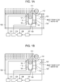
- Figs. 1A and 1B are side views showing in outline the acoustic-wave measuring apparatus according to the first embodiment of the present invention.
- Fig. 1A is a schematic diagram showing a state in which an irradiation unit 101 is out of the region imaged by a camera 103 (hereinafter the region imaged by camera 103 is referred to an image pickup region).
- Fig. 1B is a schematic diagram showing a state in which the irradiation unit 101 is moved to the image pickup region of the camera 103 and irradiates the measurement position with light.
- the acoustic-wave measuring apparatus generates light (pulsed light) from a light source (not shown) and irradiates a subject 111 using the irradiation unit 101.
- This embodiment prevents the light irradiating the subject 111 from leaking to the outside, by using a casing 100, such as a housing or outer covering made of a material that can block the irradiating light.
- a light absorbing substance (the subject to be examined, such as a tumor) in the subject 111 absorbs light energy and generates acoustic waves.
- the generated acoustic waves propagate in the subject 111 and traverse a fixed holding plate 105 to reach an acoustic-wave probe 102.
- the acoustic-wave probe 102 may also be referred to as an acoustic-wave detecting unit, and the fixed holding plate 105 may be referred to as fixed section of a holding unit.
- the acoustic-wave probe 102 receives the acoustic waves and converts them to an electrical signal and outputs the electric signal to a photoacoustic-wave processing unit 110, which is also referred to as a signal processing unit.
- the photoacoustic-wave processing unit 110 generates photoacoustic image data (reconfigures an image) using the input signal.
- the camera 103 which is an example of an image pickup unit, acquires an image of the subject 111 via a movable holding plate 104 to obtain image information.
- the movable holding plate 104 may be referred to as a movable section of the holding unit.
- a measurement-position designating unit 107 enables an observer to designate a measurement position on the basis of the image information obtained by the camera 103.
- the measurement position designated by the observer is output, as pixel coordinates, to a coordinate transforming unit 108.
- the coordinate transforming unit 108 may be implemented as a self-contained central processing unit (CPU) or a computer-implemented program.
- the coordinate transforming unit 108 transforms the pixel coordinates received from the measurement-position designating unit 107 to coordinates on the movable holding plate 104 (on-holding-plate coordinates).
- the coordinate transformation is performed using the distance between the fixed holding plate 105 and the movable holding plate 104, which is measured by a distance measuring unit 106.
- the transformed coordinates are output to a position control unit 109.
- the position control unit 109 may be either a computer-implemented program or hardware electronic circuit that can generate control signals based on the transformed coordinates.
- the position control unit 109 controls at least one of a probe driving mechanism 113 and an irradiation-unit driving mechanism 112, which are moving units, to respectively move at least one of the acoustic-wave probe 102 and the irradiation unit 101.
- the light source may include at least one coherent or incoherent pulsed light source capable of producing pulsed light of wavelengths in the biological window.
- pulsed light with a pulse width (FWHM) of several hundred nanoseconds or less and more preferably from 5 nanoseconds to 50 nanoseconds is preferable.
- the light source preferably generates light with a specified wavelength that is absorbed by a specified component (for example, hemoglobin) of components constituting a living organism.
- a preferably light source may be a laser that produces short pulses of light with a large output; but instead of the laser, a light-emitting diode may also be used.
- the laser include a solid-state laser, a gas laser, a dye laser, and a semiconductor laser, each of which may be a modulated continuous wave (CW) laser or a pulsed (e.g., mode locked) laser.
- the irradiation unit 101 irradiates the subject 111 by a method suitable for measuring the light from the light source.
- the irradiation unit 101 irradiates the subject 111 from the side opposite to the acoustic-wave probe 102
- the present invention is not limited thereto.
- the subject 111 may be irradiated either from the same side as the acoustic-wave probe 102 or from both sides of the subject 111.
- the subject 111 may be irradiated not only from one side of the subject 111 but also from a plurality of sides of the subject 111, so that the signal-to-noise ratio (S/N) of the signal can be increased.
- the irradiation unit 101 include optical components, such as a mirror or a lens that collects, magnifies, or changes the shape of light; a prism that disperses, refracts, and reflects light, one or more optical fibers, or a combination of the foregoing that can efficiently deliver light from the light source to the subject 111.
- Such optical components may be any components provided that they can irradiate the subject 111 with the light emitted from the light source by a desired method (irradiating direction, shape, and so on) in addition to the above.
- the irradiation region on the subject 111 may be movable on the subject 111, so that a wider irradiation region can be obtained.
- the irradiation unit 101 itself can be moved relative to the subject 111.
- the region of the subject 111 irradiated with light may be moved in synchronization with the acoustic-wave probe 102.
- the light source is small, the light source itself may be used as the irradiation unit 101, and the light source itself may be mechanically moved.
- the acoustic-wave probe 102 which is an acoustic-wave detecting unit, converts acoustic waves into an electrical signal.
- the acoustic-wave probe 102 may be any conversion element that can detect acoustic waves and convert the acoustic waves to an electrical signal.
- a conversion element that uses a piezoelectric phenomenon, a conversion element that uses resonance of light, and a conversion element that uses changes in capacitance may be used.
- an element array composed of a plurality of conversion elements may be used, so that acoustic waves can be received across a wide region.
- the acoustic waves are received by the acoustic-wave probe 102, and the electric signal proportional to the acoustic waves is input to the photoacoustic-wave processing unit 110.
- the acoustic-wave probe 102 in Figs. 1A and 1B is provided on the fixed holding plate 105, acoustic-wave probe 102 may be provided on the movable holding plate 104 as well.
- the photoacoustic-wave processing unit 110 which may be a signal processing section, may be either a computer-implemented program or an electronic circuit that can digitize the electric signal and generate image data corresponding to the acoustic waves received by the photoacoustic-wave probe 102.
- the photoacoustic-wave processing unit 110 generates acoustic image data (reconfigures an image) using back projection in a time domain or a Fourier domain, which is normally used in tomography technology.
- the acoustic image data in the present invention is data indicating information on the interior of the subject 111, irrespective of two-dimensional or three-dimensional data, (biological information, such as an initial sound pressure distribution and a light absorption coefficient distribution of the interior of the living organism).
- Two-dimensional photoacoustic image data is composed of a plurality of items of pixel data
- three -dimensional photoacoustic image data is composed of a plurality of items of voxel data.
- the fixed holding plate 105 and the movable holding plate 104 are holding units for holding the subject 111 and keeping the shape of at least part of the subject 111 constant. As shown in Figs. 1A and 1B , holding the subject 111 from opposing sides allows the subject 111 to be fixed in position during measurement. Advantageously, keeping the subject 111 fixed during measurement can reduce a position error due to a body motion and so on. Pressing the subject 111 allows light to efficiently reach the depths of the subject 111.
- a holding unit on which the irradiation unit 101 is provided may be a member having high light transmittance.
- a holding unit on which the acoustic-wave probe 102 is provided may be a member having a property of acoustic matching with the subject 111 and the acoustic-wave probe 102 (having similar acoustic impedance).
- an acoustic matching material such as gel, may be interposed between the holding units and the subject 111 and between the holding units and the acoustic-wave probe 102.
- the holding units are not restricted to having the above-described configuration. For example, instead of having a fixed section and a movable section, both holding plates may be movable. In addition, instead of the configuration in which the subject 111 is held by holding plates from both sides, a configuration in which the subject 111 is held from below with a bowl-shaped member may be provided.
- the casing 100 has the function of preventing the light irradiating the subject 111 from leaking to the outside by enclosing the peripheries of the irradiation unit 101, the acoustic-wave probe 102, and so on. This prevents the observer from being irradiated with light.
- the casing 100 of this embodiment also has the function of protecting the person being examined from irradiated light.
- the camera 103 which is an image pickup unit, is disposed in the casing 100 and acquires image information on the subject 111.
- Examples of the camera 103 include a charge coupled device (CCD) sensor-based camera and a complementary metal oxide semiconductor (CMOS) sensor-based camera.
- CMOS complementary metal oxide semiconductor
- the camera 103 of this embodiment is fixed to the casing 100.
- the irradiation unit 101 may be moved out of the image pickup region so as not to overlap with the subject 111.
- the camera 103 in Figs. 1A and 1B is shown near the movable holding plate 104, the camera 103 may be provided near the fixed holding plate 105.
- the irradiation-unit driving mechanism 112 which is a moving unit, can move the irradiation unit 101 to any position in or out of the image pickup region of the camera 103.
- Figs. 2A and 2B are schematic diagrams of the apparatus as viewed from the camera 103 side.
- Fig. 2A is a schematic diagram showing a state in which the irradiation unit 101 is moved out of the image pickup region of the camera 103.
- Fig. 2B is a schematic diagram showing a state in which the irradiation unit 101 is moved into the image pickup region of the camera 103.
- the irradiation-unit driving mechanism 112 has a mechanism for driving the irradiation unit 101 independently in the horizontal direction and the vertical direction. Examples of the driving mechanism include a motor and a rack-and-pinion, a motor and a belt, and a linear motor.
- the irradiation-unit driving mechanism 112 has an origin sensor 201.
- the position of the origin sensor 201 is designed so that the position of the irradiation unit 101 defined by the origin sensor 201 is out of the image pickup region of the camera 103.
- Examples of the origin sensor 201 include a contact sensor, an optical sensor, and an origin marker of an absolute encoder.
- the irradiation-unit driving mechanism 112 is controlled by the position control unit 109.
- To move the irradiation unit 101 out of the image pickup region of the camera 103 an instruction to move the irradiation unit 101 to the original position is sent from the position control unit 109 to the irradiation-unit driving mechanism 112.
- the state in Fig. 1A is achieved by moving the irradiation unit 101 out of the image pickup region of the camera 103, as shown in Fig.
- the probe driving mechanism 113 which is a moving unit, should move the acoustic-wave probe 102 to a position opposing the irradiation unit 101, with the subject 111 therebetween.
- the probe driving mechanism 113 is controlled by the position control unit 109.
- the irradiation unit 101 should be moved as described above so as to prevent the subject 111 from overlapping with the acoustic-wave probe 102 during image acquisition.
- the distance measuring unit 106 measures the distance between the fixed holding plate 105 and the movable holding plate 104.
- the distance here is a distance in the optical axis of the camera 103.
- One end of the distance measuring unit 106 is fixed to the fixed holding plate 105, and the other end is fixed to the movable holding plate 104.
- Distances that differ depending on the characteristics (sizes and so on) of the individual subjects 111 are output to the coordinate transforming unit 108.
- the measurement-position designating unit 107 is for the observer to designate a measurement position on an image acquired by the camera 103, such as mouse, keyboard or touch panel.
- An image is displayed on a display, such as a monitor, using image information from the camera 103.
- An observer designates a measurement position on the displayed image with a mouse or designates a measurement position on a screen having a contact position detection sensor with a finger.
- the measurement position may be designated by inputting the coordinates of a measurement position on the image using a keyboard or the like.
- the designated measurement position is output as pixel coordinates on the image to the coordinate transforming unit 108.
- the coordinate transforming unit 108 transforms the pixel coordinates output from the measurement-position designating unit 107 to the coordinates of a position corresponding to the pixel coordinates on the movable holding unit (on the movable holding plate 104 in this embodiment). At that time, the transformation is made using the distance between the fixed holding plate 105 and the movable holding plate 104 measured by the distance measuring unit 106. The transformed coordinates are output to the position control unit 109.
- the position control unit 109 controls the probe driving mechanism 113 and the irradiation-unit driving mechanism 112 to move at least one of the acoustic-wave probe 102 and the irradiation unit 101.
- the irradiation unit 101 can be moved to the coordinate position output from the coordinate transforming unit 108 or to an original position defined by the origin sensor 201.
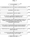
- the measurement flow of this embodiment is shown in Fig. 3 .
- the individual steps of the measurement flow will be described in detail with reference to Figs. 1A and 1B and Fig. 3 .
- the following description is made using a configuration example in which the holding units composed of the fixed holding unit and the movable holding unit is provided, and the acoustic-wave probe 102 is provided on the fixed holding unit side, and the irradiation unit 101 is provided nearer to the movable holding unit, as in Figs. 1A and 1B .
- the present invention is not limited to such a configuration, as described above.
- the measurement process is started at step 301 (abbreviated in the drawing as S301), the subject 111 is positioned between the fixed holding plate 105 and the movable holding plate 104, and the observer moves the movable holding plate 104 to hold the subject 111 in the desired position at step 302. At that time, the subject 111 may be pressed to be held as thin as possible, so as to optimize the S/N ratio of a received signal obtained and the depth of measurement. After completion of the holding, that is - once the subject 111 is positioned and held in the desired position - the distance between the fixed holding plate 105 and the movable holding plate 104 is measured by the distance measuring unit 106.
- step 303 the irradiation unit 101 is moved to the original position.
- the irradiation-unit driving mechanism 112 is driven by the position control unit 109, and the irradiation unit 101 is moved to the original position designated by the origin sensor 201.
- step 304 image pickup step
- an image of the subject 111 is acquired by the camera 103. Since the irradiation unit 101 has been moved to the original position outside the image pickup region of the camera 103 in step 303, an image of the entire subject 111 including the measurement position can be acquired.
- step 305 the observer designates the measurement position on the image using pixel coordinates on the basis of the image information on the subject 111 obtained in step 304, and thus, the pixel coordinates of the measurement position (measurement-position pixel coordinates) can be obtained.
- Fig. 4 is a graph showing pixel coordinates on the image and coordinates on the movable holding plate 104.
- the coordinate transforming unit 108 transforms the pixel coordinates (X m , Y m ) of the measurement position designated by the observer in step 305 to measurement position coordinates (x m , y m ) on the movable holding plate 104 (on-movable-holding-plate measurement position coordinates).
- the on-movable-holding-plate measurement position coordinates are expressed, for example, by values in millimeters or micrometers.
- Fig. 5 is a schematic diagram of the fixed holding plate 105, the movable holding plate 104, and the camera 103, as viewed from the top of the apparatus.
- the movable holding plate 104 can take any distance L.
- the image pickup width of the camera 103 at distance L is denoted by W(L).
- the image pickup width W changes depending on the position of the movable holding plate 104.
- Dis can be expressed as the following Exp. (1) from the relation of an isosceles triangle with the vertex at the angle of view in Fig. 5 .
- Dis L 2 ⁇ L 1 1 ⁇ W L 2 W L 1 ⁇ 1
- X denotes a horizontal pixel coordinate axis
- Y denotes a vertical pixel coordinate axis
- X m denotes a measurement-position horizontal pixel coordinate
- Y m denotes a measurement-position vertical pixel coordinate
- X w denotes an image-pickup-region-end horizontal pixel coordinate
- Y w denotes an image-pickup-region-end vertical pixel coordinate.
- x denotes an on-movable-holding-plate horizontal coordinate axis
- y denotes an on-movable-holding-plate vertical coordinate axis
- x m denotes a measurement-position horizontal coordinate
- y m denotes a measurement-position vertical coordinate
- x c denotes a horizontal coordinate at the center of image pickup region
- y c denotes a vertical coordinate at the center of image pickup region.
- Exp. (3) in Exp. (2) is a transformation coefficient determined from the distance between the camera 103 and a measurement position.
- Exp. (3) expresses an image pickup width W(L) at any distance L.
- W(L) expressed as Exp. (3) by the image-pickup-region-end horizontal pixel coordinate X w in Fig. 4 .
- the distance of an on-movable-holding-plate coordinates per pixel (Exp. (4)) can be given.
- L 1 , L 2 , W(L 1 ), and W(L 2 ) are known values measured in advance, and x c , x c , X w , and Y w are given in advance as specification values of the apparatus.
- step 307 position control step
- the irradiation unit 101 is moved by the position control unit 109 to the on-movable-holding-plate measurement position coordinates (x m , y m ) obtained in step 306. Since transformation with consideration of the distance between the fixed holding plate 105 and the movable holding plate 104 is performed in step 306, the irradiation unit 101 can be moved with high accuracy.
- the measurement position is a position on the subject 111 to be measured in more detail or a start position in the case where measurement is performed while the acoustic-wave probe 102 and the irradiation unit 101 are being moved.
- step 308 the irradiation unit 101 irradiates the subject 111 with light, and the acoustic-wave probe 102 detects generated acoustic waves to obtain a receiver signal.
- the photoacoustic-wave processing unit 110 generates photoacoustic image data using the receiver signal obtained in step 308.
- the photoacoustic image data is presented to the observer as, for example, numerical information or an image, on a display unit (not shown), and the measurement ends at step 310.
- an image pickup unit such as the camera 103
- Providing an image pickup unit, such as the camera 103 allows designation of a measurement position even in an acoustic-wave measuring apparatus in which visual designation of a measurement position is difficult. Furthermore, providing the irradiation-unit driving mechanism 112 that moves the irradiation unit 101 out of the image pickup region of the camera 103 and the distance measuring unit 106 allows high-accuracy designation of a measurement position.
- Fig. 6 is a schematic diagram showing the configuration of an acoustic-wave measuring apparatus according to a second embodiment of the present invention.
- the other components are the same as those of the first embodiment; therefore, descriptions of the same terms are omitted.
- a fixing member 801 which is a distance fixing unit, fixes the movable holding plate 104 and the camera 103 a predetermined distance.
- the fixing member 801 is designed to fix the distance between the movable holding plate 104 and the camera 103 to a certain value. Therefore, even if the movable holding plate 104 moves, the distance between the movable holding plate 104 and the camera 103 is kept constant.
- the fixing member 801 may be disposed out of the image pickup region of the camera 103.
- the coordinate transforming unit 108 transforms pixel coordinates output from the measurement-position designating unit 107 to coordinates on the movable holding plate 104. At that time, the transformation is performed using the distance determined depending on the fixing member 801. The transformed coordinates are output to the position control unit 109.
- step 906 of this embodiment differs from step 306 of the first embodiment, the other steps are the same as in Fig. 3 ; therefore, descriptions thereof will be omitted.
- Fig. 8 is a schematic diagram of the fixed holding plate 105, the movable holding plate 104, and the camera 103, as viewed from the top of the apparatus.
- Reference numerals 1001 and 1002 denote the positions of the camera 103 when the distance between the fixed holding plate 105 and the movable holding plate 104 is L 1 and L 2 , respectively. Since the distance Dis 0 between the movable holding plate 104 and the camera 103 is constant by means of the fixing member 801, the image pickup width W of the camera 103 depends on Dis 0 at either of the distances L 1 and L 2 . Referring to Figs.
- transformation equations for transforming measurement-position pixel coordinates to on-movable-holding-plate measurement position coordinates can be expressed as Exp. (7).
- ⁇ m ⁇ c + X m ⁇ X w 2 X w ⁇ W Dis 0
- y m y c ⁇ Y m ⁇ Y w 2 X w ⁇ W Dis 0
- W(Dis 0 ) in Exp. (7) is a transformation coefficient determined from the distance between the image pickup unit and a measurement position. Since Dis 0 is a specification value of the apparatus, determined depending on the fixing member 801, the transformation coefficient W(Dis 0 ) is given in advance.
- the measurement-position pixel coordinates obtained in step 305 for (X m , Y m ) in Exp. (2), the on-movable-holding-plate measurement position coordinates (x m , y m ) can be obtained.
- providing the camera 103 allows designation of a measurement position even in an acoustic-wave measuring apparatus in which visual designation of a measurement position is difficult. Furthermore, providing the fixing member 801 prevents the distance between the movable holding plate 104 and the camera 103 from changing even if the subject holding thickness changes, thereby facilitating the process of the coordinate transforming step.
- an acoustic-wave measuring apparatus enables, among other things, designation of a measurement position with high accuracy and accurate detection of acoustic waves at a desired position. While the present invention has been described with reference to exemplary embodiments, it is to be understood that the invention is not limited to the disclosed exemplary embodiments. The scope of the following claims is to be accorded the broadest interpretation so as to encompass all modifications and equivalent structures and functions.
Landscapes
- Health & Medical Sciences (AREA)
- Life Sciences & Earth Sciences (AREA)
- Physics & Mathematics (AREA)
- General Health & Medical Sciences (AREA)
- Pathology (AREA)
- Biophysics (AREA)
- Veterinary Medicine (AREA)
- Public Health (AREA)
- Animal Behavior & Ethology (AREA)
- Surgery (AREA)
- Molecular Biology (AREA)
- Medical Informatics (AREA)
- Heart & Thoracic Surgery (AREA)
- Engineering & Computer Science (AREA)
- Biomedical Technology (AREA)
- Nuclear Medicine, Radiotherapy & Molecular Imaging (AREA)
- Radiology & Medical Imaging (AREA)
- Acoustics & Sound (AREA)
- Chemical & Material Sciences (AREA)
- Reproductive Health (AREA)
- Gynecology & Obstetrics (AREA)
- Analytical Chemistry (AREA)
- Immunology (AREA)
- General Physics & Mathematics (AREA)
- Biochemistry (AREA)
- Ultra Sonic Daignosis Equipment (AREA)
- Investigating Or Analyzing Materials By The Use Of Ultrasonic Waves (AREA)
Description
- The present invention relates to an acoustic-wave measuring apparatus and an acoustic-wave measuring method.
- In particular, it relates to an acoustic-wave measuring apparatus that receives acoustic waves generated from a subject irradiated with light, as well as a method for controlling the apparatus.
- Photoacoustic tomography (PAT) is technique for in-vivo imaging using near-infrared light. In imaging with PAT, a subject, such as a living organism, is irradiated with pulsed light generated from a light source, and the light propagated and spread in the subject is absorbed by a light absorbing substance to generate acoustic waves (typically, ultrasonic waves). The mechanism of the generation of acoustic waves is known as the photoacoustic-wave effect. Tumorous tissue reacts to near-infrared light differently than peripheral tissue, it absorbs light more than the peripheral tissue to expand instantly and generate acoustic waves corresponding to the region that has absorbed the near-infrared light. A photoacoustic imaging apparatus, which is an acoustic-wave measuring apparatus, is an apparatus that receives the acoustic waves with an acoustic-wave detecting element and analyzes the received signal to thereby calculate information, such as spatial initial sound pressure distribution, on acoustic waves generated in the subject and forms an image based on the calculated information. Because the distribution of the generated sound pressure is related to a light absorption coefficient, diagnosis of a subject using the distribution related to the light absorption coefficient is currently being actively studied.
- The acoustic-wave measuring apparatus that obtains readings of a living organism using the photoacoustic-wave effect uses a high-output short-pulse (several tens of nanoseconds) light source having a near-infrared wavelength. The near-infrared wavelength band, in which light absorption of living organisms is low, is known as a biological window. Near-infrared light in the biological window can reach deep into living organisms without causing damage. Nevertheless, in an acoustic-wave measuring apparatus using PAT technology it is necessary to prevent the light from irradiating the observer, in particular, the eyes.
- To that end, for example, an apparatus described by Manohar, et al., entitled "Region-of-interest breast studies using the Twente Photoacoustic Mammoscope (PAM)", Proc. of SPIE Vol. 6437 643702, separates the subject and the observer from each other using a blackout curtain.
- On the other hand, in order to receive acoustic waves efficiently, it is desirable for the acoustic-wave measuring apparatus to move an acoustic-wave probe, which is an acoustic-wave detecting unit, to a precise predetermined measurement position of the subject and detect the acoustic waves. Furthermore, to generate acoustic waves effectively, it is desirable to move also an irradiation unit that irradiates the subject to the predetermined measurement position and irradiate the subject. For these purposes, the observer must check the measurement position on the subject and move the acoustic-wave probe and the irradiation unit to the desired measurement position. However, since the apparatus described by Manohar, et al., separates the subject and the observer from each other with the blackout curtain, it has a problem in that the observer cannot visually observe the subject and it is difficult to move the irradiation unit to the measurement position with high accuracy. Another measuring method moves the irradiation unit to the measurement position with the blackout curtain opened so as 5 to visually align the irradiation unit with the subject without irradiation of light. In this case, however, the operation of opening and closing the blackout curtain is performed for every measurement, which may often cause the observer to forget to close the blackout curtain or a gap to be generated due to incomplete closing of the blackout curtain.
- Furthermore, the document
2008/021317 A1 discloses a system for ultrasound imaging with robotic assistance. A robotic mechanism positions a volume scanning transducer at multiple acoustic windows on a patient. Ultrasound data is acquired from the windows and combined into a wide field-of-view. The robotic mechanism operates without user contact, such as for an automated full or partial torso scan of a patient. - Still further, the document Srirang Manohar: "The Twente Photoacoustic Mammoscope: system overview and performance"; (XP020084213) provides an overall overview of the Twente Photoacoustic Mammoscope, in particular, a schematic of a specific arrangement in a hospital bed.
- The present invention in its first aspect provides an acoustic-wave measuring apparatus as specified in claims 1 to 9.
- The present invention in its second aspect provides an acoustic-wave measuring method as specified in claims 10 to 13.
- Further features of the present invention will become apparent to persons having ordinary skill in the art from the following description of exemplary embodiments with reference to the attached drawings.
-
-
Fig. 1A is a schematic diagram showing in outline an acoustic-wave measuring apparatus according to a first embodiment. -
Fig. 1B is a schematic diagram of the acoustic-wave measuring apparatus. -
Fig. 2A is a schematic diagram of the apparatus as viewed from a camera. -
Fig. 2B is a schematic diagram of the apparatus as viewed from the camera. -
Fig. 3 is a flowchart of an exemplary process for measurement in the first embodiment. -
Fig. 4 is a graph showing the relationship between the pixel coordinates of a measurement position and coordinates on a movable holding plate. -
Fig. 5 is a schematic diagram of a fixed holding plate, the movable holding plate, and the camera, as viewed from the top of the apparatus. -
Fig. 6 is a schematic diagram showing in outline an acoustic-wave measuring apparatus according to a second embodiment. -
Fig. 7 is a flowchart of an exemplary process for measurement in the second embodiment. -
Fig. 8 is a schematic diagram of the fixed holding plate, the movable holding plate, and the camera, as viewed from the top of the apparatus. - In the present invention, acoustic waves include sound waves, ultrasonic waves, and photoacoustic waves and refers to elastic waves generated when a subject is irradiated with light (electromagnetic waves), such as near infrared light.
- An acoustic-wave measuring apparatus according to a first embodiment of the present invention includes a holding apparatus which holds a subject to be examined (e.g., human tissue, such as a breast) and a camera, which is an image pickup unit that acquires an image of the subject. A measurement position is designated on an image acquired by the camera, and at least one of an irradiation unit and an acoustic-wave detecting unit is moved to a corresponding position on the subject.
-
Figs. 1A and 1B are side views showing in outline the acoustic-wave measuring apparatus according to the first embodiment of the present invention.Fig. 1A is a schematic diagram showing a state in which anirradiation unit 101 is out of the region imaged by a camera 103 (hereinafter the region imaged bycamera 103 is referred to an image pickup region).Fig. 1B is a schematic diagram showing a state in which theirradiation unit 101 is moved to the image pickup region of thecamera 103 and irradiates the measurement position with light. - The acoustic-wave measuring apparatus according to the embodiment of the present invention generates light (pulsed light) from a light source (not shown) and irradiates a subject 111 using the
irradiation unit 101. This embodiment prevents the light irradiating the subject 111 from leaking to the outside, by using acasing 100, such as a housing or outer covering made of a material that can block the irradiating light. A light absorbing substance (the subject to be examined, such as a tumor) in the subject 111 absorbs light energy and generates acoustic waves. The generated acoustic waves propagate in the subject 111 and traverse a fixedholding plate 105 to reach an acoustic-wave probe 102. The acoustic-wave probe 102 may also be referred to as an acoustic-wave detecting unit, and the fixed holdingplate 105 may be referred to as fixed section of a holding unit. The acoustic-wave probe 102 receives the acoustic waves and converts them to an electrical signal and outputs the electric signal to a photoacoustic-wave processing unit 110, which is also referred to as a signal processing unit. The photoacoustic-wave processing unit 110 generates photoacoustic image data (reconfigures an image) using the input signal. Thecamera 103, which is an example of an image pickup unit, acquires an image of thesubject 111 via amovable holding plate 104 to obtain image information. Themovable holding plate 104 may be referred to as a movable section of the holding unit. A measurement-position designating unit 107 enables an observer to designate a measurement position on the basis of the image information obtained by thecamera 103. The measurement position designated by the observer is output, as pixel coordinates, to a coordinate transformingunit 108. The coordinate transformingunit 108 may be implemented as a self-contained central processing unit (CPU) or a computer-implemented program. The coordinate transformingunit 108 transforms the pixel coordinates received from the measurement-position designating unit 107 to coordinates on the movable holding plate 104 (on-holding-plate coordinates). At that time, the coordinate transformation is performed using the distance between the fixed holdingplate 105 and themovable holding plate 104, which is measured by adistance measuring unit 106. The transformed coordinates are output to aposition control unit 109. Theposition control unit 109 may be either a computer-implemented program or hardware electronic circuit that can generate control signals based on the transformed coordinates. Specifically, theposition control unit 109 controls at least one of aprobe driving mechanism 113 and an irradiation-unit driving mechanism 112, which are moving units, to respectively move at least one of the acoustic-wave probe 102 and theirradiation unit 101. - The light source, not illustrated in the present invention, may include at least one coherent or incoherent pulsed light source capable of producing pulsed light of wavelengths in the biological window. To produce a photoacoustic effect, pulsed light with a pulse width (FWHM) of several hundred nanoseconds or less and more preferably from 5 nanoseconds to 50 nanoseconds is preferable. In the case of measurement of suspect tumorous tissue, such as breast cancer or the like, the light source preferably generates light with a specified wavelength that is absorbed by a specified component (for example, hemoglobin) of components constituting a living organism. A preferably light source may be a laser that produces short pulses of light with a large output; but instead of the laser, a light-emitting diode may also be used. Examples of the laser include a solid-state laser, a gas laser, a dye laser, and a semiconductor laser, each of which may be a modulated continuous wave (CW) laser or a pulsed (e.g., mode locked) laser.
- The
irradiation unit 101 irradiates the subject 111 by a method suitable for measuring the light from the light source. Although in this embodiment theirradiation unit 101 irradiates the subject 111 from the side opposite to the acoustic-wave probe 102, the present invention is not limited thereto. For example, the subject 111 may be irradiated either from the same side as the acoustic-wave probe 102 or from both sides of the subject 111. Since the sound pressure of acoustic waves is proportional to the intensity of the light, the subject 111 may be irradiated not only from one side of the subject 111 but also from a plurality of sides of the subject 111, so that the signal-to-noise ratio (S/N) of the signal can be increased. Concrete examples of theirradiation unit 101 include optical components, such as a mirror or a lens that collects, magnifies, or changes the shape of light; a prism that disperses, refracts, and reflects light, one or more optical fibers, or a combination of the foregoing that can efficiently deliver light from the light source to the subject 111. Such optical components may be any components provided that they can irradiate the subject 111 with the light emitted from the light source by a desired method (irradiating direction, shape, and so on) in addition to the above. Furthermore, the irradiation region on the subject 111 may be movable on the subject 111, so that a wider irradiation region can be obtained. In addition, as illustrated inFigs. 1A and 1B , theirradiation unit 101 itself can be moved relative to the subject 111. Furthermore, the region of the subject 111 irradiated with light may be moved in synchronization with the acoustic-wave probe 102. In the case where the light source is small, the light source itself may be used as theirradiation unit 101, and the light source itself may be mechanically moved. - The acoustic-
wave probe 102, which is an acoustic-wave detecting unit, converts acoustic waves into an electrical signal. The acoustic-wave probe 102 may be any conversion element that can detect acoustic waves and convert the acoustic waves to an electrical signal. To that end, for example, a conversion element that uses a piezoelectric phenomenon, a conversion element that uses resonance of light, and a conversion element that uses changes in capacitance may be used. Furthermore, an element array composed of a plurality of conversion elements may be used, so that acoustic waves can be received across a wide region. The acoustic waves are received by the acoustic-wave probe 102, and the electric signal proportional to the acoustic waves is input to the photoacoustic-wave processing unit 110. Although the acoustic-wave probe 102 inFigs. 1A and 1B is provided on the fixed holdingplate 105, acoustic-wave probe 102 may be provided on themovable holding plate 104 as well. - The photoacoustic-
wave processing unit 110, which may be a signal processing section, may be either a computer-implemented program or an electronic circuit that can digitize the electric signal and generate image data corresponding to the acoustic waves received by the photoacoustic-wave probe 102. The photoacoustic-wave processing unit 110 generates acoustic image data (reconfigures an image) using back projection in a time domain or a Fourier domain, which is normally used in tomography technology. The acoustic image data in the present invention is data indicating information on the interior of the subject 111, irrespective of two-dimensional or three-dimensional data, (biological information, such as an initial sound pressure distribution and a light absorption coefficient distribution of the interior of the living organism). Two-dimensional photoacoustic image data is composed of a plurality of items of pixel data, and three -dimensional photoacoustic image data is composed of a plurality of items of voxel data. - The fixed
holding plate 105 and themovable holding plate 104 are holding units for holding the subject 111 and keeping the shape of at least part of the subject 111 constant. As shown inFigs. 1A and 1B , holding the subject 111 from opposing sides allows the subject 111 to be fixed in position during measurement. Advantageously, keeping the subject 111 fixed during measurement can reduce a position error due to a body motion and so on. Pressing the subject 111 allows light to efficiently reach the depths of the subject 111. A holding unit on which theirradiation unit 101 is provided (themovable holding plate 104 inFigs. 1A and 1B ) may be a member having high light transmittance. A holding unit on which the acoustic-wave probe 102 is provided (the fixed holdingplate 105 inFigs. 1A and 1B ) may be a member having a property of acoustic matching with the subject 111 and the acoustic-wave probe 102 (having similar acoustic impedance). To enhance the acoustic matching property, an acoustic matching material, such as gel, may be interposed between the holding units and the subject 111 and between the holding units and the acoustic-wave probe 102. The holding units are not restricted to having the above-described configuration. For example, instead of having a fixed section and a movable section, both holding plates may be movable. In addition, instead of the configuration in which the subject 111 is held by holding plates from both sides, a configuration in which the subject 111 is held from below with a bowl-shaped member may be provided. - The
casing 100 has the function of preventing the light irradiating the subject 111 from leaking to the outside by enclosing the peripheries of theirradiation unit 101, the acoustic-wave probe 102, and so on. This prevents the observer from being irradiated with light. Thecasing 100 of this embodiment also has the function of protecting the person being examined from irradiated light. - The
camera 103, which is an image pickup unit, is disposed in thecasing 100 and acquires image information on the subject 111. Examples of thecamera 103 include a charge coupled device (CCD) sensor-based camera and a complementary metal oxide semiconductor (CMOS) sensor-based camera. Thecamera 103 of this embodiment is fixed to thecasing 100. When thecamera 103 is to acquire an image of the subject 111, theirradiation unit 101 may be moved out of the image pickup region so as not to overlap with the subject 111. Although thecamera 103 inFigs. 1A and 1B is shown near themovable holding plate 104, thecamera 103 may be provided near the fixed holdingplate 105. - The irradiation-
unit driving mechanism 112, which is a moving unit, can move theirradiation unit 101 to any position in or out of the image pickup region of thecamera 103. -
Figs. 2A and 2B are schematic diagrams of the apparatus as viewed from thecamera 103 side.Fig. 2A is a schematic diagram showing a state in which theirradiation unit 101 is moved out of the image pickup region of thecamera 103.Fig. 2B is a schematic diagram showing a state in which theirradiation unit 101 is moved into the image pickup region of thecamera 103. The irradiation-unit driving mechanism 112 has a mechanism for driving theirradiation unit 101 independently in the horizontal direction and the vertical direction. Examples of the driving mechanism include a motor and a rack-and-pinion, a motor and a belt, and a linear motor. The irradiation-unit driving mechanism 112 has anorigin sensor 201. The position of theorigin sensor 201 is designed so that the position of theirradiation unit 101 defined by theorigin sensor 201 is out of the image pickup region of thecamera 103. Examples of theorigin sensor 201 include a contact sensor, an optical sensor, and an origin marker of an absolute encoder. The irradiation-unit driving mechanism 112 is controlled by theposition control unit 109. To move theirradiation unit 101 out of the image pickup region of thecamera 103, an instruction to move theirradiation unit 101 to the original position is sent from theposition control unit 109 to the irradiation-unit driving mechanism 112. Thus, the state inFig. 1A is achieved by moving theirradiation unit 101 out of the image pickup region of thecamera 103, as shown inFig. 2A . To move theirradiation unit 101 into the image pickup region of thecamera 103, an instruction to move theirradiation unit 101 to a position in the image pickup region is sent from theposition control unit 109 to the irradiation-unit driving mechanism 112. Thus, the state inFig. 1B is achieved by moving theirradiation unit 101 into the image pickup region of thecamera 103, as shown inFig. 2B . - The
probe driving mechanism 113, which is a moving unit, should move the acoustic-wave probe 102 to a position opposing theirradiation unit 101, with the subject 111 therebetween. Theprobe driving mechanism 113 is controlled by theposition control unit 109. In the case where thecamera 103 is disposed near the acoustic-wave probe 102, theirradiation unit 101 should be moved as described above so as to prevent the subject 111 from overlapping with the acoustic-wave probe 102 during image acquisition. - The
distance measuring unit 106 measures the distance between the fixed holdingplate 105 and themovable holding plate 104. The distance here is a distance in the optical axis of thecamera 103. One end of thedistance measuring unit 106 is fixed to the fixed holdingplate 105, and the other end is fixed to themovable holding plate 104. Distances that differ depending on the characteristics (sizes and so on) of theindividual subjects 111 are output to the coordinate transformingunit 108. - The measurement-
position designating unit 107 is for the observer to designate a measurement position on an image acquired by thecamera 103, such as mouse, keyboard or touch panel. An image is displayed on a display, such as a monitor, using image information from thecamera 103. An observer designates a measurement position on the displayed image with a mouse or designates a measurement position on a screen having a contact position detection sensor with a finger. The measurement position may be designated by inputting the coordinates of a measurement position on the image using a keyboard or the like. The designated measurement position is output as pixel coordinates on the image to the coordinate transformingunit 108. - The coordinate transforming
unit 108 transforms the pixel coordinates output from the measurement-position designating unit 107 to the coordinates of a position corresponding to the pixel coordinates on the movable holding unit (on themovable holding plate 104 in this embodiment). At that time, the transformation is made using the distance between the fixed holdingplate 105 and themovable holding plate 104 measured by thedistance measuring unit 106. The transformed coordinates are output to theposition control unit 109. - The
position control unit 109 controls theprobe driving mechanism 113 and the irradiation-unit driving mechanism 112 to move at least one of the acoustic-wave probe 102 and theirradiation unit 101. For example, theirradiation unit 101 can be moved to the coordinate position output from the coordinate transformingunit 108 or to an original position defined by theorigin sensor 201. Measurement Flow - The measurement flow of this embodiment is shown in
Fig. 3 . The individual steps of the measurement flow will be described in detail with reference toFigs. 1A and 1B andFig. 3 . The following description is made using a configuration example in which the holding units composed of the fixed holding unit and the movable holding unit is provided, and the acoustic-wave probe 102 is provided on the fixed holding unit side, and theirradiation unit 101 is provided nearer to the movable holding unit, as inFigs. 1A and 1B . However, the present invention is not limited to such a configuration, as described above. - First, the measurement process is started at step 301 (abbreviated in the drawing as S301), the subject 111 is positioned between the fixed holding
plate 105 and themovable holding plate 104, and the observer moves themovable holding plate 104 to hold the subject 111 in the desired position at step 302. At that time, the subject 111 may be pressed to be held as thin as possible, so as to optimize the S/N ratio of a received signal obtained and the depth of measurement. After completion of the holding, that is - once the subject 111 is positioned and held in the desired position - the distance between the fixed holdingplate 105 and themovable holding plate 104 is measured by thedistance measuring unit 106. - In step 303, the
irradiation unit 101 is moved to the original position. The irradiation-unit driving mechanism 112 is driven by theposition control unit 109, and theirradiation unit 101 is moved to the original position designated by theorigin sensor 201. - In step 304 (image pickup step), an image of the subject 111 is acquired by the
camera 103. Since theirradiation unit 101 has been moved to the original position outside the image pickup region of thecamera 103 in step 303, an image of theentire subject 111 including the measurement position can be acquired. - In step 305, the observer designates the measurement position on the image using pixel coordinates on the basis of the image information on the subject 111 obtained in step 304, and thus, the pixel coordinates of the measurement position (measurement-position pixel coordinates) can be obtained.
- A process in step 306 (coordinate transforming step) will be described with reference to
Figs. 4 and5 .Fig. 4 is a graph showing pixel coordinates on the image and coordinates on themovable holding plate 104. The coordinate transformingunit 108 transforms the pixel coordinates (Xm, Ym) of the measurement position designated by the observer in step 305 to measurement position coordinates (xm, ym) on the movable holding plate 104 (on-movable-holding-plate measurement position coordinates). The on-movable-holding-plate measurement position coordinates are expressed, for example, by values in millimeters or micrometers. - Next, transformation equations will be described.
Fig. 5 is a schematic diagram of the fixed holdingplate 105, themovable holding plate 104, and thecamera 103, as viewed from the top of the apparatus. Themovable holding plate 104 can take any distanceL. Reference numerals movable holding plate 104 when L = L1 and L = L2, respectively. The image pickup width of thecamera 103 at distance L is denoted by W(L). As shown inFig. 5 , the image pickup width W changes depending on the position of themovable holding plate 104. The distance between themovable holding plate 104 and thecamera 103 when L = L1 is denoted by Dis. Dis can be expressed as the following Exp. (1) from the relation of an isosceles triangle with the vertex at the angle of view inFig. 5 .
- From the coordinate relationship shown in
Fig. 4 , transformation equation for transforming measurement-position pixel coordinates to on-movable-holding-plate measurement position coordinates can be expressed using Dis in Exp. (1),
- Transformation of pixel coordinate Xm to position coordinate xm by Exp. (2) will be described below. Referring to
Fig. 4 , reference sign X denotes a horizontal pixel coordinate axis, Y denotes a vertical pixel coordinate axis, Xm denotes a measurement-position horizontal pixel coordinate, Ym denotes a measurement-position vertical pixel coordinate, Xw denotes an image-pickup-region-end horizontal pixel coordinate, and Yw denotes an image-pickup-region-end vertical pixel coordinate. Reference sign x denotes an on-movable-holding-plate horizontal coordinate axis, y denotes an on-movable-holding-plate vertical coordinate axis, xm denotes a measurement-position horizontal coordinate, ym denotes a measurement-position vertical coordinate, xc denotes a horizontal coordinate at the center of image pickup region, and yc denotes a vertical coordinate at the center of image pickup region.
- Exp. (3) in Exp. (2) is a transformation coefficient determined from the distance between the
camera 103 and a measurement position. Exp. (3) expresses an image pickup width W(L) at any distance L. By dividing the image pickup width W(L) expressed as Exp. (3) by the image-pickup-region-end horizontal pixel coordinate Xw inFig. 4 , the distance of an on-movable-holding-plate coordinates per pixel (Exp. (4)) can be given.
- By multiplying Exp. (5), which is the amount of pixels from the center of the image to the measurement-position horizontal pixel coordinate Xm in Exp. (2), by Exp. (4),


- By transposing xc in Exp. (6) to the left term, xm in Exp. (2) can be found. Although the above is for the horizontal direction, the same applies to the vertical direction, that is, transformation from Ym to ym.
- L1, L2, W(L1), and W(L2) are known values measured in advance, and xc, xc, Xw, and Yw are given in advance as specification values of the apparatus. By substituting the distance between the fixed holding
plate 105 and themovable holding plate 104 measured in step 302 for L in Exp. (2), and substituting the measurement-position pixel coordinates obtained in step 305 for (Xm, Ym) in Exp. (2), the on-movable-holding-plate measurement position coordinates (xm, ym) can be given. Even if the distance between themovable holding plate 104 and thecamera 103 changes, the relationship between the pixel coordinates (Xm, Ym) and the on-movable-holding-plate measurement position coordinates (xm, ym) can be corrected properly by performing step 306. - Referring back to
Fig. 3 , in step 307 (position control step), theirradiation unit 101 is moved by theposition control unit 109 to the on-movable-holding-plate measurement position coordinates (xm, ym) obtained in step 306. Since transformation with consideration of the distance between the fixed holdingplate 105 and themovable holding plate 104 is performed in step 306, theirradiation unit 101 can be moved with high accuracy. In this step, not only theirradiation unit 101 but also the acoustic-wave probe 102 should be moved to the coordinates (xm, ym) of the measurement position on the fixed holdingplate 105. Here, the measurement position is a position on the subject 111 to be measured in more detail or a start position in the case where measurement is performed while the acoustic-wave probe 102 and theirradiation unit 101 are being moved. - In step 308, the
irradiation unit 101 irradiates the subject 111 with light, and the acoustic-wave probe 102 detects generated acoustic waves to obtain a receiver signal. In step 309, the photoacoustic-wave processing unit 110 generates photoacoustic image data using the receiver signal obtained in step 308. The photoacoustic image data is presented to the observer as, for example, numerical information or an image, on a display unit (not shown), and the measurement ends at step 310. - Providing an image pickup unit, such as the
camera 103, allows designation of a measurement position even in an acoustic-wave measuring apparatus in which visual designation of a measurement position is difficult. Furthermore, providing the irradiation-unit driving mechanism 112 that moves theirradiation unit 101 out of the image pickup region of thecamera 103 and thedistance measuring unit 106 allows high-accuracy designation of a measurement position. - In a second embodiment, a case in which the distance between the image pickup unit that acquires an image of the subject and the movable holding unit is held constant will be particularly described. The other configurations are the same as those of the first embodiment.
-
Fig. 6 is a schematic diagram showing the configuration of an acoustic-wave measuring apparatus according to a second embodiment of the present invention. In this embodiment, although the details of processing in the coordinate transforming unit differ from those of the first embodiment, the other components are the same as those of the first embodiment; therefore, descriptions of the same terms are omitted. - A fixing
member 801, which is a distance fixing unit, fixes themovable holding plate 104 and the camera 103 a predetermined distance. The fixingmember 801 is designed to fix the distance between themovable holding plate 104 and thecamera 103 to a certain value. Therefore, even if themovable holding plate 104 moves, the distance between themovable holding plate 104 and thecamera 103 is kept constant. The fixingmember 801 may be disposed out of the image pickup region of thecamera 103. The coordinate transformingunit 108 transforms pixel coordinates output from the measurement-position designating unit 107 to coordinates on themovable holding plate 104. At that time, the transformation is performed using the distance determined depending on the fixingmember 801. The transformed coordinates are output to theposition control unit 109. - The measurement flow of the second embodiment is shown in
Fig. 7 . Although the coordinate transforming step (step 906) of this embodiment differs from step 306 of the first embodiment, the other steps are the same as inFig. 3 ; therefore, descriptions thereof will be omitted. - A process in
step 906 will be described with reference toFig. 8. Fig. 8 is a schematic diagram of the fixed holdingplate 105, themovable holding plate 104, and thecamera 103, as viewed from the top of the apparatus.Reference numerals camera 103 when the distance between the fixed holdingplate 105 and themovable holding plate 104 is L1 and L2, respectively. Since the distance Dis0 between themovable holding plate 104 and thecamera 103 is constant by means of the fixingmember 801, the image pickup width W of thecamera 103 depends on Dis0 at either of the distances L1 and L2. Referring toFigs. 4 and8 , transformation equations for transforming measurement-position pixel coordinates to on-movable-holding-plate measurement position coordinates can be expressed as Exp. (7).
- W(Dis0) in Exp. (7) is a transformation coefficient determined from the distance between the image pickup unit and a measurement position. Since Dis0 is a specification value of the apparatus, determined depending on the fixing
member 801, the transformation coefficient W(Dis0) is given in advance. By substituting the measurement-position pixel coordinates obtained in step 305 for (Xm, Ym) in Exp. (2), the on-movable-holding-plate measurement position coordinates (xm, ym) can be obtained. - Thus, providing the
camera 103 allows designation of a measurement position even in an acoustic-wave measuring apparatus in which visual designation of a measurement position is difficult. Furthermore, providing the fixingmember 801 prevents the distance between themovable holding plate 104 and thecamera 103 from changing even if the subject holding thickness changes, thereby facilitating the process of the coordinate transforming step. - In accordance with at least one embodiment of the present invention, an acoustic-wave measuring apparatus enables, among other things, designation of a measurement position with high accuracy and accurate detection of acoustic waves at a desired position. While the present invention has been described with reference to exemplary embodiments, it is to be understood that the invention is not limited to the disclosed exemplary embodiments. The scope of the following claims is to be accorded the broadest interpretation so as to encompass all modifications and equivalent structures and functions.
Claims (13)
- An acoustic-wave measuring apparatus comprising:holding means (104, 105) arranged to hold a subject;irradiation means (101) arranged to irradiate the subject with light;acoustic-wave detecting means (102) arranged to receive acoustic waves generated in the subject due to irradiation with the light via the holding means (104, 105);an image pickup unit (103) arranged to acquire an image of the subject;position designation means (107) configured to designate a measurement position on the image acquired by the image pickup unit (103);coordinate transforming means (108) arranged to transform coordinates of the measurement position on the image acquired by the image pickup unit (103) to coordinates of a corresponding position on the holding means (104, 105); andposition control means (109) arranged to move at least one of the irradiation means (101) and the acoustic-wave detecting means (102) to the corresponding position on the holding means (104, 105).
- The acoustic-wave measuring apparatus according to Claim 1, wherein the coordinate transforming means (108) transforms the coordinates of the measurement position on the image to the coordinates of the corresponding position on the holding means (104, 105) using a transformation coefficient determined based on a distance between the holding means (104, 105) and the image pickup unit (103).
- The acoustic-wave measuring apparatus according to Claim 1, wherein:the holding means (104, 105) includes a fixed holding section and a movable holding section arranged to hold the subject from opposite sides;the coordinate transforming means (108) transforms the coordinates of the measurement position on the image to the coordinates of the corresponding position on the movable holding section using a transformation coefficient determined based on a distance between the movable holding section and the image pickup unit (103).
- The acoustic-wave measuring apparatus according to Claim 3, further comprising distance measuring means (106) arranged to measure the distance between the movable holding section and the image pickup unit (103).
- The acoustic-wave measuring apparatus according to Claim 3, further comprising distance fixing means (801) arranged to keep a distance between a movable holding section and the image pickup unit (103) constant,
wherein the holding means (104, 105) includes a fixed holding section and the movable holding section arranged to hold the subject from opposite sides. - The acoustic-wave measuring apparatus according to any one of Claims 1 to 5, further comprising a casing, wherein the casing is configured to suppress a leakage of light with which the subject is irradiated by the irradiation means to the outside of the casing.
- The acoustic-wave measuring apparatus according to claim 6, wherein the image pickup unit is disposed inside the casing.
- The acoustic-wave measuring apparatus according to any one of claims 1 to 7, wherein the holding means holds the subject from below.
- The acoustic-wave measuring apparatus according to any one of claims 1 to 8, wherein the holding means is a bowl-shaped member.
- An acoustic-wave measuring method, carried out on an apparatus according to any of claims 1 - 9, wherein acoustic waves generated in a subject when irradiated with light by irradiation means (101) are received by an acoustic-wave detecting means (102) via holding means (104, 105), the method comprising:an image pickup step of acquiring an image of the subject;a coordinate transforming step of transforming coordinates of a measurement position, designated by an observer on the image acquired in the image pickup step to coordinates of a corresponding position on the holding means (104, 105); anda position control step of moving at least one of the irradiation means (101) and the acoustic-wave detecting means (102) to the corresponding position on the holding means (104, 105).
- The acoustic-wave measuring method according to claim 10, wherein in the coordinate transforming step, the coordinates of the measurement position on the image are transformed to the coordinates of the corresponding position on the holding means (104, 105) using a transformation coefficient determined based on a distance between the holding means (104, 105) and the image pickup unit (103).
- The acoustic-wave measuring method according to claim 10, wherein:the holding means (104, 105) include a fixed holding section and a movable holding section configured to hold the subject from opposite sides; andin the coordinate transforming step, the coordinates of the measurement position on the image are transformed to the coordinates of the corresponding position on the movable holding section using a transformation coefficient determined based on a distance between the movable holding section and the image pickup unit (103).
- The acoustic-wave measuring method according to claim 12, further comprising a distance measuring step of measuring the distance between the movable holding section and the image pickup unit (103).
Applications Claiming Priority (1)
| Application Number | Priority Date | Filing Date | Title |
|---|---|---|---|
| JP2010101300A JP5553672B2 (en) | 2010-04-26 | 2010-04-26 | Acoustic wave measuring apparatus and acoustic wave measuring method |
Publications (2)
| Publication Number | Publication Date |
|---|---|
| EP2380490A1 EP2380490A1 (en) | 2011-10-26 |
| EP2380490B1 true EP2380490B1 (en) | 2020-06-10 |
Family
ID=44117416
Family Applications (1)
| Application Number | Title | Priority Date | Filing Date |
|---|---|---|---|
| EP11161012.7A Active EP2380490B1 (en) | 2010-04-26 | 2011-04-04 | Acoustic-wave measuring apparatus and method |
Country Status (4)
| Country | Link |
|---|---|
| US (2) | US9125591B2 (en) |
| EP (1) | EP2380490B1 (en) |
| JP (1) | JP5553672B2 (en) |
| CN (1) | CN102258387B (en) |
Families Citing this family (24)
| Publication number | Priority date | Publication date | Assignee | Title |
|---|---|---|---|---|
| JP5836760B2 (en) * | 2011-11-04 | 2015-12-24 | キヤノン株式会社 | Acoustic wave acquisition apparatus and acoustic wave acquisition method |
| JP5936330B2 (en) * | 2011-11-04 | 2016-06-22 | キヤノン株式会社 | Acoustic wave measuring device and control method of acoustic wave measuring device |
| JP5871604B2 (en) | 2011-12-21 | 2016-03-01 | キヤノン株式会社 | Subject information acquisition device |
| JP2013128722A (en) * | 2011-12-22 | 2013-07-04 | Fujifilm Corp | Method and apparatus for photoacoustic imaging |
| JP6146956B2 (en) * | 2012-03-13 | 2017-06-14 | キヤノン株式会社 | Apparatus, display control method, and program |
| JP6146955B2 (en) * | 2012-03-13 | 2017-06-14 | キヤノン株式会社 | Apparatus, display control method, and program |
| JP5896812B2 (en) * | 2012-04-05 | 2016-03-30 | キヤノン株式会社 | Subject information acquisition device |
| JP6004714B2 (en) * | 2012-04-12 | 2016-10-12 | キヤノン株式会社 | Subject information acquisition apparatus and control method thereof |
| CN102824189B (en) * | 2012-08-20 | 2014-12-10 | 深圳市理邦精密仪器股份有限公司 | Ultrasonic probe timely transmitting and receiving method and device |
| JP6184146B2 (en) * | 2013-03-26 | 2017-08-23 | キヤノン株式会社 | Subject information acquisition apparatus and control method thereof |
| US10105061B2 (en) * | 2013-10-31 | 2018-10-23 | Canon Kabushiki Kaisha | Subject information obtaining apparatus |
| JP6456020B2 (en) * | 2013-11-11 | 2019-01-23 | キヤノン株式会社 | Photoacoustic measuring device |
| JP6278770B2 (en) * | 2014-03-19 | 2018-02-14 | キヤノン株式会社 | Subject information acquisition device |
| JP5774159B2 (en) * | 2014-05-19 | 2015-09-02 | キヤノン株式会社 | Acoustic wave measuring apparatus and acoustic wave measuring method |
| JP2016053482A (en) * | 2014-09-02 | 2016-04-14 | キヤノン株式会社 | Photoacoustic wave measuring apparatus and photoacoustic wave measuring method |
| CN104382558B (en) * | 2014-11-21 | 2016-06-15 | 南京星顿医疗科技有限公司 | A kind of double mode mammary gland three-dimensional image forming apparatus and method |
| CN105812969A (en) * | 2014-12-31 | 2016-07-27 | 展讯通信(上海)有限公司 | Method, system and device for picking up sound signal |
| US20170055844A1 (en) * | 2015-08-27 | 2017-03-02 | Canon Kabushiki Kaisha | Apparatus and method for acquiring object information |
| JP2017148230A (en) * | 2016-02-24 | 2017-08-31 | キヤノン株式会社 | Subject information acquisition device and information processing device |
| JP6929635B2 (en) | 2016-11-17 | 2021-09-01 | キヤノン株式会社 | Acoustic wave acquisition device and control method of acoustic wave acquisition device |
| JP2018126389A (en) * | 2017-02-09 | 2018-08-16 | キヤノン株式会社 | Information processing apparatus, information processing method, and program |
| JP6297184B2 (en) * | 2017-02-22 | 2018-03-20 | キヤノン株式会社 | Acoustic wave measuring apparatus and acoustic wave measuring method |
| KR20210034076A (en) * | 2018-07-24 | 2021-03-29 | 플루커 코포레이션 | System and method for projecting and displaying acoustic data |
| JP2019042560A (en) * | 2018-12-19 | 2019-03-22 | キヤノン株式会社 | Acoustic wave receiver |
Family Cites Families (62)
| Publication number | Priority date | Publication date | Assignee | Title |
|---|---|---|---|---|
| US4504727A (en) * | 1982-12-30 | 1985-03-12 | International Business Machines Corporation | Laser drilling system utilizing photoacoustic feedback |
| US4896673A (en) * | 1988-07-15 | 1990-01-30 | Medstone International, Inc. | Method and apparatus for stone localization using ultrasound imaging |
| EP0931516B1 (en) * | 1990-10-19 | 2008-08-20 | St. Louis University | Surgical probe locating system for head use |
| US6405072B1 (en) * | 1991-01-28 | 2002-06-11 | Sherwood Services Ag | Apparatus and method for determining a location of an anatomical target with reference to a medical apparatus |
| US6675040B1 (en) * | 1991-01-28 | 2004-01-06 | Sherwood Services Ag | Optical object tracking system |
| US5479259A (en) * | 1991-05-20 | 1995-12-26 | Hitachi, Ltd. | Method and apparatus for detecting photoacoustic signal |
| US5377006A (en) * | 1991-05-20 | 1994-12-27 | Hitachi, Ltd. | Method and apparatus for detecting photoacoustic signal |
| US5781294A (en) * | 1991-12-24 | 1998-07-14 | Hitachi, Ltd. | Method and apparatus for detecting photoacoustic signal to detect surface and subsurface information of the specimen |
| US5603318A (en) * | 1992-04-21 | 1997-02-18 | University Of Utah Research Foundation | Apparatus and method for photogrammetric surgical localization |
| DE69433588T2 (en) * | 1993-04-26 | 2005-02-03 | St. Louis University | DISPLAY OF THE POSITION OF A PROBE |
| AU3950595A (en) * | 1994-10-07 | 1996-05-06 | St. Louis University | Surgical navigation systems including reference and localization frames |
| US6167145A (en) * | 1996-03-29 | 2000-12-26 | Surgical Navigation Technologies, Inc. | Bone navigation system |
| GB9704737D0 (en) | 1997-03-07 | 1997-04-23 | Optel Instr Limited | Biological measurement system |
| US5967982A (en) * | 1997-12-09 | 1999-10-19 | The Cleveland Clinic Foundation | Non-invasive spine and bone registration for frameless stereotaxy |
| US5977538A (en) * | 1998-05-11 | 1999-11-02 | Imarx Pharmaceutical Corp. | Optoacoustic imaging system |
| WO2000063719A1 (en) * | 1999-04-20 | 2000-10-26 | Synthes Ag Chur | Device for the percutaneous obtainment of 3d-coordinates on the surface of a human or animal organ |
| ATE242865T1 (en) * | 1999-05-03 | 2003-06-15 | Synthes Ag | POSITION DETECTION DEVICE WITH AIDS FOR DETERMINING THE DIRECTION OF THE GRAVITY VECTOR |
| US6535756B1 (en) * | 2000-04-07 | 2003-03-18 | Surgical Navigation Technologies, Inc. | Trajectory storage apparatus and method for surgical navigation system |
| WO2003039370A1 (en) * | 2001-11-05 | 2003-05-15 | Computerized Medical Systems, Inc. | Apparatus and method for registration, guidance, and targeting of external beam radiation therapy |
| AU2003219843B2 (en) | 2002-02-20 | 2009-04-23 | Medicis Technologies Corporation | Ultrasonic treatment and imaging of adipose tissue |
| AU2003223072A1 (en) | 2002-04-03 | 2003-10-13 | Segami S.A.R.L. | Image registration process |
| US7068867B2 (en) * | 2003-01-02 | 2006-06-27 | Glucon Medical Ltd | Ultrasonic position indicator |
| JP3906186B2 (en) | 2003-06-27 | 2007-04-18 | 株式会社東芝 | Biological information measuring apparatus and method for measuring biological information from subject |
| JP4406226B2 (en) * | 2003-07-02 | 2010-01-27 | 株式会社東芝 | Biological information video device |
| JP4643153B2 (en) * | 2004-02-06 | 2011-03-02 | 株式会社東芝 | Non-invasive biological information imaging device |
| US7567834B2 (en) * | 2004-05-03 | 2009-07-28 | Medtronic Navigation, Inc. | Method and apparatus for implantation between two vertebral bodies |
| JP4531632B2 (en) | 2005-05-30 | 2010-08-25 | 日本電信電話株式会社 | Biological component concentration measuring apparatus and biological component concentration measuring apparatus control method |
| JP4837507B2 (en) * | 2005-10-06 | 2011-12-14 | 富士フイルム株式会社 | Breast imaging device |
| JP4490385B2 (en) | 2006-03-27 | 2010-06-23 | 日本電信電話株式会社 | Component concentration measuring device |
| JP2007282792A (en) * | 2006-04-14 | 2007-11-01 | Matsushita Electric Ind Co Ltd | Ultrasonic diagnostic system |
| WO2007148239A2 (en) * | 2006-06-23 | 2007-12-27 | Koninklijke Philips Electronics, N.V. | Timing controller for combined photoacoustic and ultrasound imager |
| US20080021317A1 (en) * | 2006-07-24 | 2008-01-24 | Siemens Medical Solutions Usa, Inc. | Ultrasound medical imaging with robotic assistance for volume imaging |
| JP2008086400A (en) | 2006-09-29 | 2008-04-17 | Gifu Univ | Mammographic image diagnostic system |
| US20080221647A1 (en) * | 2007-02-23 | 2008-09-11 | The Regents Of The University Of Michigan | System and method for monitoring photodynamic therapy |
| US7576334B2 (en) * | 2007-03-19 | 2009-08-18 | The Regents Of The University Of Michigan | Photoacoustic indicators |
| JP2009066110A (en) | 2007-09-12 | 2009-04-02 | Canon Inc | Measurement apparatus |
| WO2009073979A1 (en) * | 2007-12-12 | 2009-06-18 | Carson Jeffrey J L | Three-dimensional photoacoustic imager and methods for calibrating an imager |
| EP2281188A4 (en) * | 2008-05-30 | 2015-09-23 | Stc Unm | Photoacoustic imaging devices and methods of making and using the same |
| JP5496098B2 (en) | 2008-08-27 | 2014-05-21 | キヤノン株式会社 | Subject information acquisition apparatus and control method thereof |
| JP5451014B2 (en) * | 2008-09-10 | 2014-03-26 | キヤノン株式会社 | Photoacoustic device |
| JP2010088627A (en) * | 2008-10-07 | 2010-04-22 | Canon Inc | Apparatus and method for processing biological information |
| JP5555765B2 (en) * | 2009-04-20 | 2014-07-23 | ザ キュレイターズ オブ ザ ユニバーシティ オブ ミズーリ | Photoacoustic detection method and detection system for specimen in solid tissue |
| WO2010127199A2 (en) * | 2009-05-01 | 2010-11-04 | Visualsonics Inc. | System for photoacoustic imaging and related methods |
| JP5692988B2 (en) * | 2009-10-19 | 2015-04-01 | キヤノン株式会社 | Acoustic wave measuring device |
| JP5484024B2 (en) * | 2009-12-15 | 2014-05-07 | キヤノン株式会社 | Elastic wave receiving apparatus, elastic wave receiving method, photoacoustic apparatus, and program |
| JP5586977B2 (en) * | 2010-02-08 | 2014-09-10 | キヤノン株式会社 | Subject information acquisition apparatus and subject information acquisition method |
| JP2011183057A (en) * | 2010-03-10 | 2011-09-22 | Fujifilm Corp | Photoacoustic mammography apparatus |
| JP5917037B2 (en) * | 2011-07-29 | 2016-05-11 | キヤノン株式会社 | Subject information acquisition apparatus and subject information acquisition method |
| JP5984541B2 (en) * | 2011-08-08 | 2016-09-06 | キヤノン株式会社 | Subject information acquisition apparatus, subject information acquisition system, display control method, display method, and program |
| JP5984542B2 (en) * | 2011-08-08 | 2016-09-06 | キヤノン株式会社 | Subject information acquisition apparatus, subject information acquisition system, display control method, display method, and program |
| US9220415B2 (en) * | 2011-10-25 | 2015-12-29 | Andreas Mandelis | Systems and methods for frequency-domain photoacoustic phased array imaging |
| JP5950538B2 (en) * | 2011-10-26 | 2016-07-13 | キヤノン株式会社 | Subject information acquisition device |
| JP5843570B2 (en) * | 2011-10-31 | 2016-01-13 | キヤノン株式会社 | SUBJECT INFORMATION ACQUISITION DEVICE, CONTROL METHOD FOR THE DEVICE, AND PROGRAM |
| JP5950540B2 (en) * | 2011-10-31 | 2016-07-13 | キヤノン株式会社 | SUBJECT INFORMATION ACQUISITION DEVICE, CONTROL METHOD FOR THE DEVICE, AND PROGRAM |
| JP5936330B2 (en) * | 2011-11-04 | 2016-06-22 | キヤノン株式会社 | Acoustic wave measuring device and control method of acoustic wave measuring device |
| JP2013094539A (en) * | 2011-11-04 | 2013-05-20 | Canon Inc | Subject-information acquisition device and control method for the same |
| JP5943598B2 (en) * | 2011-12-26 | 2016-07-05 | キヤノン株式会社 | Subject information acquisition device |
| JP2013183915A (en) * | 2012-03-08 | 2013-09-19 | Canon Inc | Object information acquiring apparatus |
| JP6016387B2 (en) * | 2012-03-09 | 2016-10-26 | キヤノン株式会社 | Subject information acquisition apparatus and calibration apparatus |
| JP5896812B2 (en) * | 2012-04-05 | 2016-03-30 | キヤノン株式会社 | Subject information acquisition device |
| JP6004714B2 (en) * | 2012-04-12 | 2016-10-12 | キヤノン株式会社 | Subject information acquisition apparatus and control method thereof |
| JP6238550B2 (en) * | 2013-04-17 | 2017-11-29 | キヤノン株式会社 | SUBJECT INFORMATION ACQUISITION DEVICE AND METHOD FOR CONTROLLING SUBJECT INFORMATION ACQUISITION DEVICE |
-
2010
- 2010-04-26 JP JP2010101300A patent/JP5553672B2/en not_active Expired - Fee Related
-
2011
- 2011-04-04 EP EP11161012.7A patent/EP2380490B1/en active Active
- 2011-04-18 US US13/088,495 patent/US9125591B2/en not_active Expired - Fee Related
- 2011-04-26 CN CN201110104689.9A patent/CN102258387B/en not_active Expired - Fee Related
-
2015
- 2015-08-05 US US14/818,995 patent/US10722211B2/en active Active
Non-Patent Citations (1)
| Title |
|---|
| None * |
Also Published As
| Publication number | Publication date |
|---|---|
| US10722211B2 (en) | 2020-07-28 |
| US20150335253A1 (en) | 2015-11-26 |
| US9125591B2 (en) | 2015-09-08 |
| JP5553672B2 (en) | 2014-07-16 |
| US20110263963A1 (en) | 2011-10-27 |
| CN102258387B (en) | 2014-05-21 |
| JP2011229620A (en) | 2011-11-17 |
| CN102258387A (en) | 2011-11-30 |
| EP2380490A1 (en) | 2011-10-26 |
Similar Documents
| Publication | Publication Date | Title |
|---|---|---|
| EP2380490B1 (en) | Acoustic-wave measuring apparatus and method | |
| EP2533697B1 (en) | Photoacoustic imaging apparatus and photoacoustic imaging method | |
| US9116111B2 (en) | Acoustic signal receiving apparatus and imaging apparatus | |
| US9433355B2 (en) | Photoacoustic imaging apparatus and photoacoustic imaging method | |
| US10178956B2 (en) | Subject information acquisition apparatus | |
| EP2482713B1 (en) | Photoacoustic measuring apparatus | |
| JP2010088873A (en) | Biological information imaging apparatus | |
| JP5675390B2 (en) | measuring device | |
| US20150335251A1 (en) | Object information acquiring apparatus and object information acquiring method | |
| EP2740410A1 (en) | Subject information acquisition device, method for controlling subject information acquisition device, and program therefor | |
| JP6184146B2 (en) | Subject information acquisition apparatus and control method thereof | |
| US20200085345A1 (en) | Object information acquisition apparatus and method of controlling the same | |
| JP6100322B2 (en) | Acoustic wave measuring apparatus and acoustic wave measuring method | |
| JP5774159B2 (en) | Acoustic wave measuring apparatus and acoustic wave measuring method | |
| JP6297184B2 (en) | Acoustic wave measuring apparatus and acoustic wave measuring method | |
| JP2016002373A (en) | Object information acquisition apparatus | |
| JP6942556B2 (en) | Shading member and photoacoustic device | |
| US20150374239A1 (en) | Object information acquiring apparatus and control method of object information acquiring apparatus | |
| JP2019042560A (en) | Acoustic wave receiver |
Legal Events
| Date | Code | Title | Description |
|---|---|---|---|
| AK | Designated contracting states |
Kind code of ref document: A1 Designated state(s): AL AT BE BG CH CY CZ DE DK EE ES FI FR GB GR HR HU IE IS IT LI LT LU LV MC MK MT NL NO PL PT RO RS SE SI SK SM TR |
|
| AX | Request for extension of the european patent |
Extension state: BA ME |
|
| PUAI | Public reference made under article 153(3) epc to a published international application that has entered the european phase |
Free format text: ORIGINAL CODE: 0009012 |
|
| 17P | Request for examination filed |
Effective date: 20120426 |
|
| STAA | Information on the status of an ep patent application or granted ep patent |
Free format text: STATUS: EXAMINATION IS IN PROGRESS |
|
| 17Q | First examination report despatched |
Effective date: 20170323 |
|
| GRAP | Despatch of communication of intention to grant a patent |
Free format text: ORIGINAL CODE: EPIDOSNIGR1 |
|
| STAA | Information on the status of an ep patent application or granted ep patent |
Free format text: STATUS: GRANT OF PATENT IS INTENDED |
|
| INTG | Intention to grant announced |
Effective date: 20191121 |
|
| RAP1 | Party data changed (applicant data changed or rights of an application transferred) |
Owner name: CANON KABUSHIKI KAISHA |
|
| GRAS | Grant fee paid |
Free format text: ORIGINAL CODE: EPIDOSNIGR3 |
|
| GRAA | (expected) grant |
Free format text: ORIGINAL CODE: 0009210 |
|
| STAA | Information on the status of an ep patent application or granted ep patent |
Free format text: STATUS: THE PATENT HAS BEEN GRANTED |
|
| AK | Designated contracting states |
Kind code of ref document: B1 Designated state(s): AL AT BE BG CH CY CZ DE DK EE ES FI FR GB GR HR HU IE IS IT LI LT LU LV MC MK MT NL NO PL PT RO RS SE SI SK SM TR |
|
| REG | Reference to a national code |
Ref country code: GB Ref legal event code: FG4D |
|
| REG | Reference to a national code |
Ref country code: CH Ref legal event code: EP Ref country code: AT Ref legal event code: REF Ref document number: 1278559 Country of ref document: AT Kind code of ref document: T Effective date: 20200615 |
|
| REG | Reference to a national code |
Ref country code: DE Ref legal event code: R096 Ref document number: 602011067218 Country of ref document: DE |
|
| REG | Reference to a national code |
Ref country code: IE Ref legal event code: FG4D |
|
| REG | Reference to a national code |
Ref country code: LT Ref legal event code: MG4D |
|
| PG25 | Lapsed in a contracting state [announced via postgrant information from national office to epo] |
Ref country code: GR Free format text: LAPSE BECAUSE OF FAILURE TO SUBMIT A TRANSLATION OF THE DESCRIPTION OR TO PAY THE FEE WITHIN THE PRESCRIBED TIME-LIMIT Effective date: 20200911 Ref country code: NO Free format text: LAPSE BECAUSE OF FAILURE TO SUBMIT A TRANSLATION OF THE DESCRIPTION OR TO PAY THE FEE WITHIN THE PRESCRIBED TIME-LIMIT Effective date: 20200910 Ref country code: LT Free format text: LAPSE BECAUSE OF FAILURE TO SUBMIT A TRANSLATION OF THE DESCRIPTION OR TO PAY THE FEE WITHIN THE PRESCRIBED TIME-LIMIT Effective date: 20200610 Ref country code: SE Free format text: LAPSE BECAUSE OF FAILURE TO SUBMIT A TRANSLATION OF THE DESCRIPTION OR TO PAY THE FEE WITHIN THE PRESCRIBED TIME-LIMIT Effective date: 20200610 Ref country code: FI Free format text: LAPSE BECAUSE OF FAILURE TO SUBMIT A TRANSLATION OF THE DESCRIPTION OR TO PAY THE FEE WITHIN THE PRESCRIBED TIME-LIMIT Effective date: 20200610 |
|
| REG | Reference to a national code |
Ref country code: NL Ref legal event code: MP Effective date: 20200610 |
|
| PG25 | Lapsed in a contracting state [announced via postgrant information from national office to epo] |
Ref country code: HR Free format text: LAPSE BECAUSE OF FAILURE TO SUBMIT A TRANSLATION OF THE DESCRIPTION OR TO PAY THE FEE WITHIN THE PRESCRIBED TIME-LIMIT Effective date: 20200610 Ref country code: LV Free format text: LAPSE BECAUSE OF FAILURE TO SUBMIT A TRANSLATION OF THE DESCRIPTION OR TO PAY THE FEE WITHIN THE PRESCRIBED TIME-LIMIT Effective date: 20200610 Ref country code: RS Free format text: LAPSE BECAUSE OF FAILURE TO SUBMIT A TRANSLATION OF THE DESCRIPTION OR TO PAY THE FEE WITHIN THE PRESCRIBED TIME-LIMIT Effective date: 20200610 Ref country code: BG Free format text: LAPSE BECAUSE OF FAILURE TO SUBMIT A TRANSLATION OF THE DESCRIPTION OR TO PAY THE FEE WITHIN THE PRESCRIBED TIME-LIMIT Effective date: 20200910 |
|
| REG | Reference to a national code |
Ref country code: AT Ref legal event code: MK05 Ref document number: 1278559 Country of ref document: AT Kind code of ref document: T Effective date: 20200610 |
|
| PG25 | Lapsed in a contracting state [announced via postgrant information from national office to epo] |
Ref country code: NL Free format text: LAPSE BECAUSE OF FAILURE TO SUBMIT A TRANSLATION OF THE DESCRIPTION OR TO PAY THE FEE WITHIN THE PRESCRIBED TIME-LIMIT Effective date: 20200610 Ref country code: AL Free format text: LAPSE BECAUSE OF FAILURE TO SUBMIT A TRANSLATION OF THE DESCRIPTION OR TO PAY THE FEE WITHIN THE PRESCRIBED TIME-LIMIT Effective date: 20200610 |
|
| PG25 | Lapsed in a contracting state [announced via postgrant information from national office to epo] |
Ref country code: PT Free format text: LAPSE BECAUSE OF FAILURE TO SUBMIT A TRANSLATION OF THE DESCRIPTION OR TO PAY THE FEE WITHIN THE PRESCRIBED TIME-LIMIT Effective date: 20201012 Ref country code: ES Free format text: LAPSE BECAUSE OF FAILURE TO SUBMIT A TRANSLATION OF THE DESCRIPTION OR TO PAY THE FEE WITHIN THE PRESCRIBED TIME-LIMIT Effective date: 20200610 Ref country code: CZ Free format text: LAPSE BECAUSE OF FAILURE TO SUBMIT A TRANSLATION OF THE DESCRIPTION OR TO PAY THE FEE WITHIN THE PRESCRIBED TIME-LIMIT Effective date: 20200610 Ref country code: RO Free format text: LAPSE BECAUSE OF FAILURE TO SUBMIT A TRANSLATION OF THE DESCRIPTION OR TO PAY THE FEE WITHIN THE PRESCRIBED TIME-LIMIT Effective date: 20200610 Ref country code: AT Free format text: LAPSE BECAUSE OF FAILURE TO SUBMIT A TRANSLATION OF THE DESCRIPTION OR TO PAY THE FEE WITHIN THE PRESCRIBED TIME-LIMIT Effective date: 20200610 Ref country code: EE Free format text: LAPSE BECAUSE OF FAILURE TO SUBMIT A TRANSLATION OF THE DESCRIPTION OR TO PAY THE FEE WITHIN THE PRESCRIBED TIME-LIMIT Effective date: 20200610 Ref country code: SM Free format text: LAPSE BECAUSE OF FAILURE TO SUBMIT A TRANSLATION OF THE DESCRIPTION OR TO PAY THE FEE WITHIN THE PRESCRIBED TIME-LIMIT Effective date: 20200610 Ref country code: IT Free format text: LAPSE BECAUSE OF FAILURE TO SUBMIT A TRANSLATION OF THE DESCRIPTION OR TO PAY THE FEE WITHIN THE PRESCRIBED TIME-LIMIT Effective date: 20200610 |
|
| PG25 | Lapsed in a contracting state [announced via postgrant information from national office to epo] |
Ref country code: PL Free format text: LAPSE BECAUSE OF FAILURE TO SUBMIT A TRANSLATION OF THE DESCRIPTION OR TO PAY THE FEE WITHIN THE PRESCRIBED TIME-LIMIT Effective date: 20200610 Ref country code: SK Free format text: LAPSE BECAUSE OF FAILURE TO SUBMIT A TRANSLATION OF THE DESCRIPTION OR TO PAY THE FEE WITHIN THE PRESCRIBED TIME-LIMIT Effective date: 20200610 Ref country code: IS Free format text: LAPSE BECAUSE OF FAILURE TO SUBMIT A TRANSLATION OF THE DESCRIPTION OR TO PAY THE FEE WITHIN THE PRESCRIBED TIME-LIMIT Effective date: 20201010 |
|
| REG | Reference to a national code |
Ref country code: DE Ref legal event code: R097 Ref document number: 602011067218 Country of ref document: DE |
|
| PLBE | No opposition filed within time limit |
Free format text: ORIGINAL CODE: 0009261 |
|
| STAA | Information on the status of an ep patent application or granted ep patent |
Free format text: STATUS: NO OPPOSITION FILED WITHIN TIME LIMIT |
|
| PG25 | Lapsed in a contracting state [announced via postgrant information from national office to epo] |
Ref country code: DK Free format text: LAPSE BECAUSE OF FAILURE TO SUBMIT A TRANSLATION OF THE DESCRIPTION OR TO PAY THE FEE WITHIN THE PRESCRIBED TIME-LIMIT Effective date: 20200610 |
|
| 26N | No opposition filed |
Effective date: 20210311 |
|
| PG25 | Lapsed in a contracting state [announced via postgrant information from national office to epo] |
Ref country code: SI Free format text: LAPSE BECAUSE OF FAILURE TO SUBMIT A TRANSLATION OF THE DESCRIPTION OR TO PAY THE FEE WITHIN THE PRESCRIBED TIME-LIMIT Effective date: 20200610 |
|
| PGFP | Annual fee paid to national office [announced via postgrant information from national office to epo] |
Ref country code: DE Payment date: 20210323 Year of fee payment: 11 |
|
| PG25 | Lapsed in a contracting state [announced via postgrant information from national office to epo] |
Ref country code: MC Free format text: LAPSE BECAUSE OF FAILURE TO SUBMIT A TRANSLATION OF THE DESCRIPTION OR TO PAY THE FEE WITHIN THE PRESCRIBED TIME-LIMIT Effective date: 20200610 |
|
| GBPC | Gb: european patent ceased through non-payment of renewal fee |
Effective date: 20210404 |
|
| PG25 | Lapsed in a contracting state [announced via postgrant information from national office to epo] |
Ref country code: LU Free format text: LAPSE BECAUSE OF NON-PAYMENT OF DUE FEES Effective date: 20210404 |
|
| REG | Reference to a national code |
Ref country code: BE Ref legal event code: MM Effective date: 20210430 |
|
| PG25 | Lapsed in a contracting state [announced via postgrant information from national office to epo] |
Ref country code: LI Free format text: LAPSE BECAUSE OF NON-PAYMENT OF DUE FEES Effective date: 20210430 Ref country code: CH Free format text: LAPSE BECAUSE OF NON-PAYMENT OF DUE FEES Effective date: 20210430 Ref country code: FR Free format text: LAPSE BECAUSE OF NON-PAYMENT OF DUE FEES Effective date: 20210430 Ref country code: GB Free format text: LAPSE BECAUSE OF NON-PAYMENT OF DUE FEES Effective date: 20210404 |
|
| PG25 | Lapsed in a contracting state [announced via postgrant information from national office to epo] |
Ref country code: IE Free format text: LAPSE BECAUSE OF NON-PAYMENT OF DUE FEES Effective date: 20210404 |
|
| PG25 | Lapsed in a contracting state [announced via postgrant information from national office to epo] |
Ref country code: IS Free format text: LAPSE BECAUSE OF FAILURE TO SUBMIT A TRANSLATION OF THE DESCRIPTION OR TO PAY THE FEE WITHIN THE PRESCRIBED TIME-LIMIT Effective date: 20201010 |
|
| PG25 | Lapsed in a contracting state [announced via postgrant information from national office to epo] |
Ref country code: BE Free format text: LAPSE BECAUSE OF NON-PAYMENT OF DUE FEES Effective date: 20210430 |
|
| REG | Reference to a national code |
Ref country code: DE Ref legal event code: R119 Ref document number: 602011067218 Country of ref document: DE |
|
| PG25 | Lapsed in a contracting state [announced via postgrant information from national office to epo] |
Ref country code: DE Free format text: LAPSE BECAUSE OF NON-PAYMENT OF DUE FEES Effective date: 20221103 |
|
| PG25 | Lapsed in a contracting state [announced via postgrant information from national office to epo] |
Ref country code: HU Free format text: LAPSE BECAUSE OF FAILURE TO SUBMIT A TRANSLATION OF THE DESCRIPTION OR TO PAY THE FEE WITHIN THE PRESCRIBED TIME-LIMIT; INVALID AB INITIO Effective date: 20110404 Ref country code: CY Free format text: LAPSE BECAUSE OF FAILURE TO SUBMIT A TRANSLATION OF THE DESCRIPTION OR TO PAY THE FEE WITHIN THE PRESCRIBED TIME-LIMIT Effective date: 20200610 |
|
| PG25 | Lapsed in a contracting state [announced via postgrant information from national office to epo] |
Ref country code: MK Free format text: LAPSE BECAUSE OF FAILURE TO SUBMIT A TRANSLATION OF THE DESCRIPTION OR TO PAY THE FEE WITHIN THE PRESCRIBED TIME-LIMIT Effective date: 20200610 |