EP2376988B1 - Standardisation of data used for monitoring an aircraft engine - Google Patents
Standardisation of data used for monitoring an aircraft engine Download PDFInfo
- Publication number
- EP2376988B1 EP2376988B1 EP09803852.4A EP09803852A EP2376988B1 EP 2376988 B1 EP2376988 B1 EP 2376988B1 EP 09803852 A EP09803852 A EP 09803852A EP 2376988 B1 EP2376988 B1 EP 2376988B1
- Authority
- EP
- European Patent Office
- Prior art keywords
- indicators
- indicator
- estimator
- engine
- time
- Prior art date
- Legal status (The legal status is an assumption and is not a legal conclusion. Google has not performed a legal analysis and makes no representation as to the accuracy of the status listed.)
- Active
Links
- 238000012544 monitoring process Methods 0.000 title claims description 18
- 238000000034 method Methods 0.000 claims description 40
- 238000005259 measurement Methods 0.000 claims description 36
- 230000009466 transformation Effects 0.000 claims description 16
- 238000004458 analytical method Methods 0.000 claims description 14
- 238000000844 transformation Methods 0.000 claims description 14
- 230000006870 function Effects 0.000 claims description 12
- 238000013528 artificial neural network Methods 0.000 claims description 6
- 238000004590 computer program Methods 0.000 claims description 5
- 238000011156 evaluation Methods 0.000 claims description 5
- 238000011425 standardization method Methods 0.000 claims description 5
- 238000009472 formulation Methods 0.000 claims description 3
- 239000000203 mixture Substances 0.000 claims description 3
- 238000012417 linear regression Methods 0.000 claims description 2
- 238000012545 processing Methods 0.000 description 10
- 230000000694 effects Effects 0.000 description 4
- 239000000446 fuel Substances 0.000 description 4
- 230000001133 acceleration Effects 0.000 description 3
- 238000004364 calculation method Methods 0.000 description 3
- 238000012550 audit Methods 0.000 description 2
- 239000006185 dispersion Substances 0.000 description 2
- 230000010006 flight Effects 0.000 description 2
- 230000003287 optical effect Effects 0.000 description 2
- 238000000513 principal component analysis Methods 0.000 description 2
- 230000002123 temporal effect Effects 0.000 description 2
- 230000001594 aberrant effect Effects 0.000 description 1
- 230000002159 abnormal effect Effects 0.000 description 1
- 230000004075 alteration Effects 0.000 description 1
- 238000007906 compression Methods 0.000 description 1
- 230000006835 compression Effects 0.000 description 1
- 238000010276 construction Methods 0.000 description 1
- 230000006378 damage Effects 0.000 description 1
- 238000007405 data analysis Methods 0.000 description 1
- 230000001934 delay Effects 0.000 description 1
- 238000013461 design Methods 0.000 description 1
- 238000001514 detection method Methods 0.000 description 1
- 230000007613 environmental effect Effects 0.000 description 1
- 230000004907 flux Effects 0.000 description 1
- 230000014509 gene expression Effects 0.000 description 1
- 230000010365 information processing Effects 0.000 description 1
- 238000005461 lubrication Methods 0.000 description 1
- 238000012423 maintenance Methods 0.000 description 1
- 238000004377 microelectronic Methods 0.000 description 1
- 238000010606 normalization Methods 0.000 description 1
- 230000008569 process Effects 0.000 description 1
- 230000000717 retained effect Effects 0.000 description 1
- 238000013432 robust analysis Methods 0.000 description 1
- 238000012360 testing method Methods 0.000 description 1
Images

Classifications
-
- G—PHYSICS
- G05—CONTROLLING; REGULATING
- G05B—CONTROL OR REGULATING SYSTEMS IN GENERAL; FUNCTIONAL ELEMENTS OF SUCH SYSTEMS; MONITORING OR TESTING ARRANGEMENTS FOR SUCH SYSTEMS OR ELEMENTS
- G05B23/00—Testing or monitoring of control systems or parts thereof
- G05B23/02—Electric testing or monitoring
- G05B23/0205—Electric testing or monitoring by means of a monitoring system capable of detecting and responding to faults
- G05B23/0218—Electric testing or monitoring by means of a monitoring system capable of detecting and responding to faults characterised by the fault detection method dealing with either existing or incipient faults
- G05B23/0221—Preprocessing measurements, e.g. data collection rate adjustment; Standardization of measurements; Time series or signal analysis, e.g. frequency analysis or wavelets; Trustworthiness of measurements; Indexes therefor; Measurements using easily measured parameters to estimate parameters difficult to measure; Virtual sensor creation; De-noising; Sensor fusion; Unconventional preprocessing inherently present in specific fault detection methods like PCA-based methods
-
- G—PHYSICS
- G05—CONTROLLING; REGULATING
- G05B—CONTROL OR REGULATING SYSTEMS IN GENERAL; FUNCTIONAL ELEMENTS OF SUCH SYSTEMS; MONITORING OR TESTING ARRANGEMENTS FOR SUCH SYSTEMS OR ELEMENTS
- G05B23/00—Testing or monitoring of control systems or parts thereof
- G05B23/02—Electric testing or monitoring
- G05B23/0205—Electric testing or monitoring by means of a monitoring system capable of detecting and responding to faults
- G05B23/0218—Electric testing or monitoring by means of a monitoring system capable of detecting and responding to faults characterised by the fault detection method dealing with either existing or incipient faults
- G05B23/0224—Process history based detection method, e.g. whereby history implies the availability of large amounts of data
- G05B23/024—Quantitative history assessment, e.g. mathematical relationships between available data; Functions therefor; Principal component analysis [PCA]; Partial least square [PLS]; Statistical classifiers, e.g. Bayesian networks, linear regression or correlation analysis; Neural networks
Definitions
- the present invention relates to the field of surveillance of an aircraft engine.
- the invention relates to a standardization of data used for monitoring the aircraft engine.
- an effective anomaly detector must be able to detect a fault in any context.
- it is very expensive to maintain a monitoring application continuously and moreover, it is very difficult to perform specific calculations for each phase of flight and each external condition.
- a monitoring tool must function identically regardless of the external conditions of acquisition and data. So, it is necessary before any surveillance, to reduce to a standard environment.
- the standardization method is a conventional standardization method which merely calculates the average of each monitoring indicator defined from the measurements collected on the aircraft engine, calculating the difference between this average and the measurement read, and then divide the difference by a standard deviation. Mean and standard deviation are calculated a priori on a series of previously digitized data.
- PCA Principal Component Analysis
- This method makes it possible to standardize the indicators by removing dependencies on the external context while managing the stochastic interdependence relations between the indicators themselves.
- the surveillance of the aircraft engine can operate identically regardless of the external conditions of acquisition.
- the standardized values can be considered as observations acquired under strictly identical conditions for each engine monitoring or each flight of the aircraft.
- Analytical transformations can of course include an identity transformation.
- the space can be formed from the subset of indicators and the exogenous data set as well as by analytical applications on these same data. This makes it possible to provide information on the physics of data that is standardized and possibly allows to enter a knowledge that can improve the relevance of the model.
- the standardized values are not abstract quantities but well standardized signatures of the initial indicators, in the same dimensions, while being free of dependency relationships with the context of acquisition. This not only reduces aircraft engine monitoring to a standard environment, but also facilitates the interpretation of expert monitoring.
- said time measurements are collected during normal operation of said aircraft engine.
- the standardized values are easy to calculate and continue to have a clear meaning for the experts while being independent of the flight conditions.
- the method comprises an analysis of a robustness of each estimator according to a cross evaluation technique making it possible to choose an optimal projection space.
- the cross evaluation technique is very easy to implement because of the large amount of normal operational data.
- said projection space is constructed according to expert criteria using physical formulations of the relationships between the indicators as well as between the indicators and the exogenous data.
- the engine expert remains at all times able to interpret and interact with the model.
- said space is automatically constructed using a neural network.
- the model is able to look for it itself by analyzing the data. in normal operation.
- said neural network may be a kernel model.
- the indicators of said set of indicators Y (y 1 , ..., y j , ..., y m ) are specific to physical and / or logical elements of said engine.
- the indicators can indicate a particular element or a specific task of a whole set of elements of the engine thus making it possible to better analyze the performance and the state of the engine.
- the indicators of said set of indicators Y (y l , ..., y j , ..., y m ) can be calculated according to expertise criteria by constructing a FMEA.
- the indicators can be identified by identifying particular points or particular functions summarizing details or shapes of certain curves representative of said temporal measures.
- the exogenous data X (x l , ..., x n ) intervening on the indicators are identified according to expertise criteria by a dependency analysis allowing to list the contextual data related to the indicators.
- said regression may be a linear regression.
- the invention is also directed to a computer program comprising instructions for carrying out the standardization method according to the above steps when it is executed by processing means.
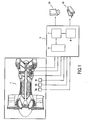
- the figure 1 illustrates hardware means implemented in the data standardization system or method used for monitoring an aircraft engine 1 according to the invention.
- This system comprises several sensors 3a-3f for measuring data reflecting the state of the engine 1 as well as external or internal context data which may affect the operation of the engine 1.
- the system also comprises information processing means 5 such as a computer or computer that can be used for executing a computer program designed to implement the method according to the invention.
- the processing means 5 comprise the hardware means usually found in a computer. More particularly, these processing means 5 comprise a central unit 7 which executes the instruction sequences of the program according to the method of the invention, a central memory 9 which stores the data and programs in progress, media or means 11 storage of digital data retaining the data, input devices (sensors 3a-3f, keyboard, mouse, ...) and output devices (screen 13, printer 15, ...) to perceive the result of standardization.
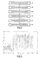
- the figure 2 illustrates the main steps implemented by the processing means 5 to standardize the data used for monitoring the aircraft engine.
- Step E1 relates to the identification of the raw measurements from which it will be possible in principle to extract useful information on the aircraft engine 1 to be monitored.
- the processing means 5 are configured to collect and digitize, over time, time measurements acquired by the 3d-3f sensors on the aircraft engine 1. operation as well as contextual measures acquired by the sensors 3a-3c representative of the external environmental conditions.
- the number of sensors 3a-3f is not very important, but acquired at different frequencies, the elements that can be retained can be very numerous.
- 9 to 12 sensors can be installed to measure pressures, fluxes and temperatures at a low frequency of 32Hz and 4 sensors to measure engine 1 shaft rotation speeds and engine vibration. 1 at a high frequency up to 20kHz or more.
- time measurements can be very easily collected during normal operation of the aircraft engine 1, given the wide availability of such measurements.
- Stage E2 concerns the definition of indicators.
- the indicators may be specific to physical elements indicating a particular element of the engine 1 or logical elements indicating a specific task of a whole set of elements of the engine 1. More particularly, a physical element is a real component of the engine. engine 1 such as, for example, the HP base reactor, the stator valves, etc.
- a system or logic element refers to a group of components of the engine 1 performing a specific task such as the starting system, the lubrication system, the performance, etc.
- the indicators Y (y l , ..., y j , ..., y m ) can be calculated according to expertise criteria.
- experts can formulate indicators in a document called FMEA (Failure Mode, Effects and Criticality Analysis) or FMECA (Failure Modes, Effects and Criticality Analysis).
- FMEA Feilure Mode, Effects and Criticality Analysis
- FMECA Feilure Modes, Effects and Criticality Analysis
- the indicators can be identified by "pointers", for example by locating particular points or particular functions summarizing details or shapes of certain curves representative of time measurements.
- the experts will, for example, focus on measurements of temperatures, pressures, and fuel flow. Then they can build wear indicators, for example, in terms of fuel consumption from one flight to another.
- the vibration specialists will isolate specific frequencies of the rotation times depending on the dimensions of the different elements of the shaft: radius of the rings, diameters of the balls, etc.
- each measurement collected during a flight is performed under particular external or internal conditions. These conditions, which can have an impact on the reading of the indicators, are recorded.
- External conditions may include external temperatures and pressures, the attitude and relative speed of the aircraft, but also the place of flight (above sea, desert, land, etc.), weather conditions ( rain, snow, frost, etc.), humidity, and so on.
- the internal conditions may concern the specific use of the engine (shaft speed, exhaust gas temperature, fuel type, etc.). All these measures can be considered as exogenous data.
- the figure 3 is a graphical representation showing the oil temperature just before starting the engine.
- oil temperature we notice immediately that there are two types of starts corresponding to cold starts and hot starts. This is typically a case where an internal data (oil temperature) is considered as context data that clearly differentiates two classes of starts that must be taken into account in the data analysis.
- the exogenous data X (x l , ..., x n ) intervening on the indicators can be identified according to expertise criteria.
- an automatic dependency analysis (by studying correlations or mutual information) also makes it possible to quickly list the contextual data related to the indicators.
- the figure 4 illustrates a graphical representation of the starting delay of the engine 1 using an auxiliary power unit APU, as a function of the time required for the engine 1 to reach its nominal speed on the ground.
- the dotted line curve c1 denotes a first dispersion level around the average and the dashed line curve c2 denotes a second dispersion level around the average.
- the distribution of the points of the figure 4 clearly shows that there is a relationship between the starting time of the engine 1 and the time required for the latter to reach its nominal speed on the ground.
- the relationship between these two indicators may depend on exogenous data such as the outdoor temperature or the outlet pressure of the APU.
- Steps E4 and E5 concern the construction of estimators associated with the indicators calculated in step E2.
- Analytical transformations express physical relationships between indicators and can be defined by experts. These analytical transformations may include, in addition to an identity transformation, linear or non-linear transformations or functions providing information on correlations between the different indicators.
- the regression can be of the neural network type using, for example, a kernel model and a least squares minimization. Alternatively, the regression may be of linear type.
- each indicator we build a regression of the observations on the space generated by the other indicators, the context data, expressions resulting from the analysis of the experts and other functions implemented for example, in the form of a kernel model.
- the constructed space on which the observations are projected is much larger than the number of initial indicators.
- the projection space can be constructed according to criteria of expertise using physical formulations of the relationships between the indicators as well as between the indicators and the exogenous data.
- the expertise of the expert can be exploited not only for the identification of variables but also in the definition of the projection space.
- Other classic examples may relate to state variables such as enthalpy or energy. For example, if the energy corresponds to a product of two indicators, then for a constant energy the inverse of an indicator makes it possible to predict the other indicator.
- the projection space can also be automatically constructed using a neural network, for example, of the core model type.
- a neural network for example, of the core model type.
- all options can be used simultaneously by default.
- non-linear transformations of the indicator that may be easier to predict. These transformations can be selected from a list of possibilities (logarithm, inverse, saturation, ). By default, all acceptable transformations are tested and a selection is made according to a robustness criterion.
- each estimator can be carried out according to a cross evaluation technique making it possible to choose the best projection space. This technique can be reapplied to invertible functions of each projected estimator, derived from expert analysis. The best regression will be preserved, for example, it can it is easier to model the logarithm of an indicator than its value itself.
- the residual of the model (the observation minus the estimate) can be added to a mean or reference value considered as a standard value of the indicator.
- the standardized indicators will oscillate around their respective average values according to the errors predicted by the model.
- a normal observation is naturally an observation for which all the residues are small (that is, less than a multiple of the standard deviation ⁇ of the distribution of the estimated error which is anyway known).
- the signals will be far from their average values.
- Figures 5A and 5B illustrate the graphical representations of an indicator representing the time to reach the maximum acceleration of the LP low pressure shaft (in ordinate) after each engine start (as abscissa).
- the dashed lines c11 denote levels +/- 3 ⁇ around the mean value and the dashed lines c12 denote levels +/- 6 ⁇ around the average value.
- FIG. 5A illustrates the signals of the initial indicator before standardization and Figure 5B illustrates the signals of the indicator after the standardization according to the invention.
- the Figure 5A shows that there are 6 signals s1-s6 (between start cycle number 50 and number 90) that are different from the average and are slower to start.
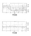
- Figures 6A and 6B Another example is given by Figures 6A and 6B .
- the Figure 6A is a graphical representation of the values of a non-standard initial indicator representing the gradient of the exhaust gas temperatures measured on an aircraft engine in normal operation during successive flights.
- Figure 6B illustrates the graphical representation after standardization of the inductor of the Figure 6A according to the present invention. This shows that the values of the standardized indicator can be considered observations acquired under strictly identical conditions for each engine monitoring during each flight of the aircraft. Indeed, the standardization of the indicators according to the present invention eliminates the dependencies vis-à-vis the external context and takes into account relationships of stochastic interdependencies between the indicators themselves.
- the Figure 6B shows that in normal engine operation, the probability of observing a signal deviating from the mean value by a value greater than 3 ⁇ is less than 3.10 -3 and that greater than 6 ⁇ is less than 2.10 -9 . This clearly shows that the monitoring of an element of the aircraft engine can function identically regardless of the external conditions of acquisition. Thus, the application to an anomaly detection tool is not only simplified but much easier to interpret by experts.
- the invention also relates to a computer program product, this program being capable of being implemented in the processing means or a computer system, this program comprising code instructions adapted to the implementation of a method according to the invention as described above.
- This program can use any programming language, and be in the form of source code, object code, or intermediate code between source code and object code, such as in a partially compiled form, or in any other form desirable shape.
- a computer-readable information carrier may be used with instructions from a computer program as mentioned above.
- the information carrier may be any entity or device capable of storing the program.
- the medium may include storage means, such as a ROM, for example a CD ROM or a microelectronic circuit ROM, or other recording means.
- the information medium may be a transmissible medium such as an electrical or optical signal, which may be conveyed via an electrical or optical cable, by radio or by other means.
- the information carrier may be an integrated circuit in which the program is incorporated, the circuit being adapted to execute or to be used in the execution of the method in question.
Description
La présente invention se rapporte au domaine de surveillance d'un moteur d'aéronef. En particulier, l'invention concerne une standardisation de données utilisées pour la surveillance du moteur d'aéronef.The present invention relates to the field of surveillance of an aircraft engine. In particular, the invention relates to a standardization of data used for monitoring the aircraft engine.
Dans de nombreuses industries, telles que l'aéronautique ou le spatial, il est fondamental de maîtriser le comportement du moteur pour améliorer l'efficacité de conception et de maintenance. Ceci dépend de la capacité d'acquérir et de traiter des données mesurées par des capteurs de surveillance.In many industries, such as aeronautics or space, it is essential to control engine behavior to improve design and maintenance efficiency. This depends on the ability to acquire and process data measured by surveillance sensors.
Un des problèmes rencontrés par les experts du moteur lors de l'interprétation ou l'analyse des mesures est le fait qu'un moteur donné ne fonctionne jamais sous exactement les mêmes conditions. En effet, pour un moteur d'aéronef lors de vols opérationnels, les conditions d'acquisition de mesures sont systématiquement différentes : elles dépendent du pilotage, de la météo, du trajet, de l'état du moteur, etc.One of the problems experienced by engine experts when interpreting or analyzing measurements is that a given engine never runs under exactly the same conditions. In fact, for an aircraft engine during operational flights, the measurement acquisition conditions are systematically different: they depend on the control, the weather, the route, the state of the engine, etc.
Cependant, un détecteur d'anomalie efficace doit être capable de détecter une faute en n'importe quel contexte. Toutefois, il est très coûteux de maintenir une application de monitoring en continu et de plus, il est très difficile de réaliser des calculs spécifiques pour chaque phase de vol et chaque condition extérieure.However, an effective anomaly detector must be able to detect a fault in any context. However, it is very expensive to maintain a monitoring application continuously and moreover, it is very difficult to perform specific calculations for each phase of flight and each external condition.
Ainsi, un outil de surveillance se doit de fonctionner identiquement quelles que soient les conditions extérieures d'acquisition et de données. Alors, il est nécessaire avant toute surveillance, de se ramener à un environnement standard.Thus, a monitoring tool must function identically regardless of the external conditions of acquisition and data. So, it is necessary before any surveillance, to reduce to a standard environment.
Actuellement, la méthode de standardisation est une méthode de normalisation classique qui se contente de calculer la moyenne de chaque indicateur de surveillance défini à partir des mesures recueillies sur le moteur d'aéronef, de calculer la différence entre cette moyenne et la mesure lue, et puis de diviser la différence par un écart-type. La moyenne et l'écart-type sont calculés a priori sur une série de données précédemment numérisées.Currently, the standardization method is a conventional standardization method which merely calculates the average of each monitoring indicator defined from the measurements collected on the aircraft engine, calculating the difference between this average and the measurement read, and then divide the difference by a standard deviation. Mean and standard deviation are calculated a priori on a series of previously digitized data.
L'inconvénient de cette méthode est qu'elle ne sait ni gérer les dépendances vis-à-vis de données exogènes ni gérer les relations de dépendances entre les indicateurs eux-mêmes.The disadvantage of this method is that it does not know how to manage dependencies on exogenous data or how to manage dependency relationships between the indicators themselves.
Il existe d'autres méthodes qui consistent à créer des modes de normalisations multivariés à partir d'algorithmes de compression comme l'ACP (Analyse en composantes principales). Cependant, celles-ci réclament un important temps de calcul et aboutissent à des indicateurs sans dimension qui ne peuvent pas être interprétés par les experts du moteur.There are other methods of creating multivariate normalization modes from compression algorithms such as PCA (Principal Component Analysis). However, these require significant computing time and result in dimensionless indicators that can not be interpreted by the engine experts.
La présente invention concerne un procédé de standardisation de données utilisées pour la surveillance d'un moteur d'aéronef, comportant les étapes suivantes :
- recueillir au cours du temps des mesures temporelles sur ledit moteur d'aéronef ;
- calculer à partir desdites mesures temporelles un ensemble d'indicateurs Y = (yl,..., y j ,..., y m ) spécifiques à des éléments dudit moteur ;
- identifier à partir desdites mesures temporelles un ensemble de données exogènes X = (xl,...,x) représentatives du contexte extérieur intervenant sur ledit ensemble d'indicateurs Y ;
- définir un modèle multidimensionnel conditionnel gérant simultanément les indicateurs dudit ensemble d'indicateurs Y en prenant en compte ledit ensemble de données exogènes X pour former un ensemble d'estimateurs Ŷ = (ŷl,...,ŷj,...,ŷm) correspondant audit ensemble d'indicateurs Y = (yl,...,yj,...,ym) ; et
- normaliser chaque estimateur ŷj en fonction d'une valeur de référence de l'indicateur correspondant yj et d'un écart entre ledit chaque estimateur ŷj et ledit indicateur correspondant yj pour former un ensemble de valeurs standardisées Ỹ = (ỹl,...,ỹj,...,ỹm).
- collecting temporal measurements over time on said aircraft engine;
- calculating from said time measurements a set of indicators Y = (y 1 , ..., y j , ..., y m ) specific to elements of said engine;
- identifying from said time measurements a set of exogenous data X = (x 1 , ..., x) representative of the external context intervening on said set of indicators Y;
- define a conditional multidimensional model simultaneously managing the indicators of said set of indicators Y taking into account said set of exogenous data X to form a set of estimators Ŷ = (ŷ l , ..., ŷ j , ..., ŷ m ) corresponding to said set of indicators Y = (y l , ..., y j , ..., y m ); and
- normalize each estimator ŷ j according to a reference value of the corresponding indicator y j and a difference between said each estimator ŷ j and said corresponding indicator y j to form a set of standardized values Ỹ = (ỹ l , ..., ỹ j , ..., ỹ m ).
Ce procédé permet de standardiser les indicateurs en supprimant des dépendances vis-à-vis du contexte extérieur tout en gérant les relations d'interdépendances stochastiques entre les indicateurs eux-mêmes. Ainsi, la surveillance du moteur d'aéronef peut fonctionner identiquement quelles que soient les conditions extérieures d'acquisition. En effet, les valeurs standardisées peuvent être considérées comme des observations acquises dans des conditions strictement identiques pour chaque surveillance du moteur ou chaque vol de l'aéronef.This method makes it possible to standardize the indicators by removing dependencies on the external context while managing the stochastic interdependence relations between the indicators themselves. Thus, the surveillance of the aircraft engine can operate identically regardless of the external conditions of acquisition. Indeed, the standardized values can be considered as observations acquired under strictly identical conditions for each engine monitoring or each flight of the aircraft.
Conformément à l'invention, la définition dudit modèle multidimensionnel conditionnel comporte les étapes suivantes :
- construire pour chaque indicateur yj dudit ensemble d'indicateurs Y, un espace de projection E (j) = σ(Y(j), X) engendré par des transformations analytiques d'un sous-ensemble d'indicateurs Y(j) = (yl,..., yj-1, yj+1,...ym) comprenant tous les indicateurs dudit ensemble d'indicateurs Y sauf ledit chaque indicateur yj et par ledit ensemble de données exogènes X ; et
- calculer pour ledit chaque indicateur yj dudit ensemble d'indicateurs Y un estimateur correspondant ŷj en projetant selon une technique de régression ledit chaque indicateur yj sur ledit espace de projection E(j) = σ(Y(j), X) formant ainsi ledit ensemble d'estimateurs Ŷ = (ŷl,..., ŷj,...,ŷm).
- construct for each indicator y j of said set of indicators Y , a projection space E (j) = σ (Y (j) , X) generated by analytic transformations of a subset of indicators Y (j) = (y l , ..., y j-1 , y j + 1 , ... y m ) including all the indicators of said set of indicators Y except said each indicator y j and by said set of exogenous data X; and
- calculating for said each indicator y j of said set of indicators Y an estimator corresponding to en j by projecting according to a regression technique said each indicator y j onto said projection space E (j) = σ (Y (j) , X) forming thus said set of estimators Ŷ = (ŷ l , ..., ŷ j , ..., ŷ m ).
Les transformations analytiques peuvent bien entendu comporter une transformation identité. Ainsi l'espace peut être formé à partir du sous-ensemble d'indicateurs et de l'ensemble de données exogènes ainsi que par des applications analytiques sur ces mêmes données. Ceci permet d'apporter des informations sur la physique des données que l'on standardise et permet éventuellement de rentrer une connaissance qui peut améliorer la pertinence du modèle. De plus, les valeurs standardisées ne sont pas des grandeurs abstraites mais bien des signatures standardisées des indicateurs initiaux, dans les mêmes dimensions, tout en étant débarrassées des relations de dépendance avec le contexte d'acquisition. Ceci permet non seulement de ramener la surveillance du moteur d'aéronef à un environnement standard mais permet aussi de faciliter l'interprétation de la surveillance par les experts.Analytical transformations can of course include an identity transformation. Thus the space can be formed from the subset of indicators and the exogenous data set as well as by analytical applications on these same data. This makes it possible to provide information on the physics of data that is standardized and possibly allows to enter a knowledge that can improve the relevance of the model. In addition, the standardized values are not abstract quantities but well standardized signatures of the initial indicators, in the same dimensions, while being free of dependency relationships with the context of acquisition. This not only reduces aircraft engine monitoring to a standard environment, but also facilitates the interpretation of expert monitoring.
Avantageusement, lesdites mesures temporelles sont recueillies en fonctionnement normal dudit moteur d'aéronef.Advantageously, said time measurements are collected during normal operation of said aircraft engine.
Ainsi, il est très facile d'acquérir ces mesures temporelles car le plus souvent le moteur fonctionne normalement. De plus, en exploitant uniquement des données opérationnelles normales pour se calibrer, le modèle multidimensionnel est facile à contrôler en terme de robustesse vu la grande disponibilité de telles mesures.Thus, it is very easy to acquire these time measurements because most often the engine operates normally. Moreover, by using only normal operational data to calibrate itself, the multidimensional model is easy to control in terms of robustness given the wide availability of such measurements.
Chaque valeur standardisée ỹj peut être calculée en ajoutant une valeur moyenne ou de référence de l'indicateur correspondant y̅j à un écart entre l'indicateur correspondant yj et l'estimateur correspondant ŷj selon l'équation suivante ỹj = y̅j + (yj - y̅j).Each standardized value ỹ j can be calculated by adding a mean or reference value of the corresponding indicator y̅ j to a difference between the corresponding indicator y j and the corresponding estimator ŷ j according to the following equation ỹ j = y̅ j + (y j - y̅ j ).
Ainsi, les valeurs standardisées sont faciles à calculer et continuent d'avoir une signification claire pour les experts tout en étant indépendantes des conditions de vol.Thus, the standardized values are easy to calculate and continue to have a clear meaning for the experts while being independent of the flight conditions.
Avantageusement, le procédé comporte une analyse d'une robustesse de chaque estimateur selon une technique d'évaluation croisée permettant de choisir un espace de projection optimal.Advantageously, the method comprises an analysis of a robustness of each estimator according to a cross evaluation technique making it possible to choose an optimal projection space.
La technique d'évaluation croisée est très facile à implémenter à cause de la grande quantité des données opérationnelles normales.The cross evaluation technique is very easy to implement because of the large amount of normal operational data.
Selon une particularité de la présente invention, ledit espace de projection est construit suivant des critères d'expertises à l'aide de formulations physiques des relations entre les indicateurs ainsi qu'entre les indicateurs et les données exogènes.According to a feature of the present invention, said projection space is constructed according to expert criteria using physical formulations of the relationships between the indicators as well as between the indicators and the exogenous data.
Ainsi, en identifiant la manière dont les données sont reliées entre elles à partir des connaissances physiques des mesures, l'expert moteur reste à tout moment capable d'interpréter et d'interagir avec le modèle.Thus, by identifying the way in which the data are linked together from the physical knowledge of the measurements, the engine expert remains at all times able to interpret and interact with the model.
Selon une autre particularité, ledit espace est construit de manière automatique en utilisant un réseau de neurones.In another feature, said space is automatically constructed using a neural network.
Ainsi, quand l'expert ne dispose pas de connaissances a priori sur les relations entre les indicateurs eux-mêmes et/ou les relations entre les indicateurs et les données exogènes, le modèle est capable d'en rechercher lui-même en analysant les données en fonctionnement normal.Thus, when the expert does not have knowledge a priori on the relations between the indicators themselves and / or the relations between the indicators and the exogenous data, the model is able to look for it itself by analyzing the data. in normal operation.
En particulier, ledit réseau de neurones peut être un modèle à noyaux.In particular, said neural network may be a kernel model.
Avantageusement, les indicateurs dudit ensemble d'indicateurs Y = (yl,...,yj,..., ym) sont spécifiques à des éléments physiques et/ou logiques dudit moteur.Advantageously, the indicators of said set of indicators Y = (y 1 , ..., y j , ..., y m ) are specific to physical and / or logical elements of said engine.
Ainsi, les indicateurs peuvent indiquer un élément particulier ou une tâche spécifique de tout un ensemble d'éléments du moteur permettant alors de mieux analyser la performance et l'état du moteur.Thus, the indicators can indicate a particular element or a specific task of a whole set of elements of the engine thus making it possible to better analyze the performance and the state of the engine.
Les indicateurs dudit ensemble d'indicateurs Y=(yl,...,yj,...,ym) peuvent être calculés suivant des critères d'expertise en construisant une AMDEC.The indicators of said set of indicators Y = (y l , ..., y j , ..., y m ) can be calculated according to expertise criteria by constructing a FMEA.
Ceci permet d'exploiter la connaissance des experts en motorisation pour recueillir les indicateurs utiles à l'analyse du moteur.This allows to exploit the knowledge of experts in motorization to collect the indicators useful for engine analysis.
Les indicateurs peuvent être identifiés par un repérage de points particuliers ou de fonctions particulières résumant des détails ou des formes de certaines courbes représentatives desdites mesures temporelles.The indicators can be identified by identifying particular points or particular functions summarizing details or shapes of certain curves representative of said temporal measures.
Avantageusement, les données exogènes X = (xl,..., xn) intervenant sur les indicateurs sont identifiées suivant des critères d'expertise par une analyse de dépendance permettant de lister les données contextuelles liées aux indicateurs.Advantageously, the exogenous data X = (x l , ..., x n ) intervening on the indicators are identified according to expertise criteria by a dependency analysis allowing to list the contextual data related to the indicators.
Selon une particularité de la présente invention, ladite régression peut être une régression linéaire.According to a feature of the present invention, said regression may be a linear regression.
L'invention vise également un système de standardisation de données utilisées pour la surveillance d'un moteur d'aéronef comportant :
- des moyens pour recueillir au cours du temps des mesures temporelles sur ledit moteur d'aéronef ;
- des moyens pour calculer à partir desdites mesures temporelles un ensemble d'indicateurs Y = (yl,..., yj,..., ym) spécifiques à des éléments dudit moteur ;
- des moyens pour identifier à partir desdites mesures temporelles un ensemble de données exogènes X = (xl,..., xn) représentatives du contexte extérieur intervenant sur ledit ensemble d'indicateurs Y ;
- des moyens pour définir un modèle multidimensionnel conditionnel gérant simultanément les indicateurs dudit ensemble d'indicateurs Y en prenant en compte ledit ensemble de données exogènes X pour former un ensemble d'estimateurs Ŷ = (ŷl,...,ŷj,...,ŷm) correspondant audit ensemble d'indicateurs Y = (yl,..., yj,..., ym), comprenant :
- des moyens pour construire pour chaque indicateur yj dudit ensemble d'indicateurs Y, un espace de projection E(j) = σ(Y(j), X) engendré par des transformations analytiques d'un sous-ensemble d'indicateurs Y(j) = (yl,..., yj-l, yj+l,...ym) comprenant tous les indicateurs dudit ensemble d'indicateurs Y sauf ledit chaque indicateur yj et par ledit ensemble de données exogènes X ; et
- des moyens pour calculer pour ledit chaque indicateur yj dudit ensemble d'indicateurs Y un estimateur correspondant ŷj en projetant selon une technique de régression ledit chaque indicateur yj sur ledit espace de projection E(j) = σ(Y(j), X) formant ainsi ledit ensemble d'estimateurs Ŷ = (ŷl,...,ŷj,...,ŷm); et
- des moyens pour normaliser chaque estimateur ŷj en fonction d'une valeur de référence de l'indicateur correspondant yj et d'un écart entre ledit chaque estimateur ŷj et ledit indicateur correspondant yj pour former un ensemble de valeurs standardisées Ỹ = (ỹl,...,ỹj,...,ỹm).
- means for collecting over time measurements on said aircraft engine;
- means for calculating from said time measurements a set of Y = (y l , ..., y j , ..., y m ) indicators specific to elements of said engine;
- means for identifying from said time measurements a set of exogenous data X = (x 1 , ..., x n ) representative of the external context occurring on said set of Y indicators;
- means for defining a conditional multidimensional model simultaneously managing the indicators of said set of Y indicators by taking into account said set of exogenous data X to form a set of estimators Ŷ = (ŷ 1 , ..., ŷ j , .. ., ŷ m ) corresponding to said set of indicators Y = (y 1 , ..., y j , ..., y m ), comprising:
- means for constructing for each indicator y j of said set of indicators Y, a projection space E (j) = σ (Y (j) , X) generated by analytic transformations of a subset of indicators Y ( j) = (y l , ..., y jl , y + 1 , ... y m ) including all the indicators of said set of indicators Y except said each indicator y j and said set of exogenous data X; and
- means for calculating for each said indicator y j of said set of indicators Y an estimator corresponding to en j by projecting according to a regression technique said each indicator y j onto said projection space E (j) = σ (Y (j) , X) thus forming said set of estimators Ŷ = (ŷ 1 , ..., ŷ j , ..., ŷ m ); and
- means for normalizing each estimator ŷ j according to a reference value of the corresponding indicator y j and a difference between said each estimator ŷ j and said corresponding indicator y j to form a set of standardized values Ỹ = (ỹ l , ..., ỹ j , ..., ỹ m ).
L'invention vise aussi un programme d'ordinateur comportant des instructions pour la mise en oeuvre du procédé de standardisation selon les étapes ci-dessus lorsqu'il est exécuté par des moyens de traitement.The invention is also directed to a computer program comprising instructions for carrying out the standardization method according to the above steps when it is executed by processing means.
D'autres particularités et avantages du dispositif et du procédé selon l'invention ressortiront mieux à la lecture de la description faite ci-après, à titre indicatif mais non limitatif, en référence aux dessins annexés sur lesquels :
- la
figure 1 illustre des moyens matériels mis en oeuvre dans le système ou procédé qui peuvent être employés pour la standardisation de données utilisées pour la surveillance d'un moteur d'aéronef selon l'invention ; - la
figure 2 est un organigramme illustrant les étapes principales pour standardiser les données utilisées pour la surveillance du moteur d'aéronef de lafigure 1 ; - la
figure 3 est une représentation graphique illustrant la température d'huile juste avant le démarrage du moteur d'aéronef de lafigure 1 ; - la
figure 4 est une représentation graphique illustrant des délais d'étapes de démarrage du moteur d'aéronef de lafigure 1 ; - les
figures 5A et 5B sont des représentations graphiques illustrant le délai d'atteindre une accélération maximale de l'arbre basse pression après chaque démarrage du moteur d'aéronef de lafigure 1 ; et - les
figures 6A et 6B sont des représentations graphiques illustrant le gradient des températures des gaz d'échappement mesurées sur le moteur d'aéronef de lafigure 1 .
- the
figure 1 illustrates hardware means implemented in the system or method that may be employed for the standardization of data used for monitoring an aircraft engine according to the invention; - the
figure 2 is a flowchart illustrating the main steps to standardize the data used for the aircraft engine monitoring of thefigure 1 ; - the
figure 3 is a graphical representation illustrating the oil temperature just before the start of the aircraft engine of thefigure 1 ; - the
figure 4 is a graphical representation illustrating delays in starting stages of the aircraft engine of thefigure 1 ; - the
Figures 5A and 5B are graphical representations illustrating the delay in achieving maximum acceleration of the low pressure shaft after each start of the aircraft engine of thefigure 1 ; and - the
Figures 6A and 6B are graphical representations illustrating the gradient of the exhaust gas temperatures measured on the aircraft engine of thefigure 1 .
La
Ce système comprend plusieurs capteurs 3a-3f pour mesurer des données reflétant l'état du moteur 1 ainsi que des données de contexte externes ou internes pouvant affecter le fonctionnement du moteur 1. Le système comprend aussi des moyens de traitement 5 de l'information tel un calculateur ou ordinateur pouvant être utilisé pour l'exécution d'un programme informatique conçu pour mettre en oeuvre le procédé selon l'invention. Les moyens de traitement 5 comprennent les moyens matériels que l'on trouve habituellement dans un ordinateur. Plus particulièrement, ces moyens de traitement 5 comprennent une unité centrale 7 qui exécute les séquences d'instructions du programme selon le procédé de l'invention, une mémoire centrale 9 qui stocke les données et programmes en cours d'exécution, des supports ou moyens de stockage 11 de données numériques conservant les données, des périphériques d'entrées (capteurs 3a-3f, clavier, souris, ...) ainsi que des périphériques de sorties (écran 13, imprimante 15,...) pour percevoir le résultat de la standardisation.This system comprises
Conformément à l'invention, la
L'étape E1 concerne l'identification des mesures brutes à partir desquelles il sera a priori possible d'extraire de l'information utile sur le moteur 1 d'aéronef à surveiller. En effet, les moyens de traitement 5 sont configurés pour recueillir et numériser au cours du temps des mesures temporelles acquises par les capteurs 3d-3f sur le moteur 1 d'aéronef en exploitation ainsi que des mesures contextuelles acquises par les capteurs 3a-3c représentatives des conditions environnementales extérieures.Step E1 relates to the identification of the raw measurements from which it will be possible in principle to extract useful information on the
Dans des conditions opérationnelles, le nombre de capteurs 3a-3f n'est pas très important, mais acquises à des fréquences différentes, les éléments que l'on peut en retenir peuvent être très nombreux. Par exemple, pour un moteur CFM, on peut installer 9 à 12 capteurs pour mesurer des pressions, des flux et des températures à une faible fréquence de 32Hz et 4 capteurs pour mesurer des vitesses de rotation des arbres du moteur 1 et des vibrations du moteur 1 à une haute fréquence allant jusqu'à 20kHz ou plus.In operational conditions, the number of
Par ailleurs, on notera que, les mesures temporelles peuvent être très facilement recueillies en fonctionnement normal du moteur 1 d'aéronef vu la grande disponibilité de telles mesures.Furthermore, it will be noted that the time measurements can be very easily collected during normal operation of the
L'étape E2 concerne la définition des indicateurs. Ainsi, les moyens de traitement 5 sont configurés pour calculer à partir des mesures temporelles un ensemble d'indicateurs Y = (yl,..., yj,..., ym) spécifiques à des éléments du moteur 1.Stage E2 concerns the definition of indicators. Thus, the processing means 5 are configured to calculate from the time measurements a set of indicators Y = (y 1 , ..., y j , ..., y m ) specific to elements of the
On notera que les indicateurs peuvent être spécifiques à des éléments physiques indiquant un élément particulier du moteur 1 ou à des éléments logiques indiquant une tâche spécifique de tout un ensemble d'éléments du moteur 1. Plus particulièrement, un élément physique est un composant réel du moteur 1 comme par exemple, le réacteur de base HP, les vannes stators, etc. Un système ou élément logique se réfère à un groupe de composants du moteur 1 réalisant une tâche spécifique comme le système de démarrage, le système de lubrification, la performance, etc.Note that the indicators may be specific to physical elements indicating a particular element of the
Par ailleurs, les indicateurs Y = (yl,..., yj,..., ym) peuvent être calculés suivant des critères d'expertise. Par exemple, les experts peuvent formuler les indicateurs dans un document appelé AMDEC (Analyse des modes de défaillance, de leurs effets et de leur criticité) ou FMECA (Failure Modes, Effects and Criticality Analysis, en anglais). Ce document liste les défaillances, les équipements concernés, les causes, les conséquences, mais aussi les indicateurs calculés à partir des mesures précédentes permettant de relever le phénomène avec pour chacun une description des effets observés. De plus, chaque faute peut être décrite par l'effet observé sur les résultats spécifiques calculés à partir des mesures temporelles.In addition, the indicators Y = (y l , ..., y j , ..., y m ) can be calculated according to expertise criteria. For example, experts can formulate indicators in a document called FMEA (Failure Mode, Effects and Criticality Analysis) or FMECA (Failure Modes, Effects and Criticality Analysis). This document lists the failures, the equipment concerned, the causes, the consequences, but also the indicators calculated from the previous measurements making it possible to identify the phenomenon with for each a description of the effects observed. In addition, each fault can be described by the effect observed on the specific results calculated from the time measurements.
Les indicateurs peuvent être identifiés par des « pointeurs » comme par exemple, par un repérage de points particuliers ou de fonctions particulières résumant des détails ou des formes de certaines courbes représentatives des mesures temporelles.The indicators can be identified by "pointers", for example by locating particular points or particular functions summarizing details or shapes of certain curves representative of time measurements.
Par exemple, pour analyser la capacité de démarrage du moteur 1, les experts vont extraire différentes durées et valeurs spécifiques ou des calculs qui ont une signification claire sur le démarrage. Parmi ces indicateurs, on peut définir un indicateur de délai indiquant le temps qu'il faut pour que l'arbre HP (Haute pression) du moteur atteigne une vitesse donnée après l'ouverture de la soupape de carburant. On peut aussi considérer un indicateur sur l'accélération maximale de l'arbre HP ainsi que beaucoup d'autres indicateurs similaires.For example, to analyze the starting capacity of
Pour l'analyse de performance, les experts vont par exemple, se focaliser sur les mesures de températures, de pressions, et de l'écoulement du carburant. Ensuite, ils peuvent construire des indicateurs d'usures s'exprimant par exemple, en termes de consommation de carburant d'un vol à un autre.For performance analysis, the experts will, for example, focus on measurements of temperatures, pressures, and fuel flow. Then they can build wear indicators, for example, in terms of fuel consumption from one flight to another.
Pour l'analyse de portée d'arbre du moteur 1, les spécialistes de vibration vont isoler des fréquences spécifiques des temps de rotation dépendant des dimensions des différents éléments de l'arbre : rayon des anneaux, diamètres des billes, etc.For the shaft range analysis of the
L'étape E3 concerne l'identification des conditions extérieures. Plus particulièrement, les moyens de traitement 5 sont configurés pour identifier à partir des mesures temporelles un ensemble de données exogènes X = (x1,...,xn) représentatives du contexte extérieur intervenant sur l'ensemble d'indicateurs Y.Step E3 relates to the identification of external conditions. More particularly, the processing means 5 are configured to identify from time measurements a set of data exogenous X = (x 1 , ..., x n ) representative of the external context intervening on the set of indicators Y.
En effet, chaque mesure recueillie lors d'un vol est réalisée dans des conditions externes ou internes particulières. Ces conditions qui peuvent avoir un impact sur la lecture des indicateurs sont enregistrées. Les conditions externes peuvent comprendre les températures et pressions extérieures, l'attitude et la vitesse relative de l'avion, mais aussi le lieu de vol (au dessus de la mer, le désert, la terre, etc.), les conditions météo (pluie, neige, gel, etc.), l'hygrométrie, et ainsi de suite. Les conditions internes peuvent concerner l'utilisation spécifique du moteur (vitesse de l'arbre, température des gaz d'échappement, type du carburant, etc.). Toutes ces mesures peuvent être considérées comme des données exogènes.Indeed, each measurement collected during a flight is performed under particular external or internal conditions. These conditions, which can have an impact on the reading of the indicators, are recorded. External conditions may include external temperatures and pressures, the attitude and relative speed of the aircraft, but also the place of flight (above sea, desert, land, etc.), weather conditions ( rain, snow, frost, etc.), humidity, and so on. The internal conditions may concern the specific use of the engine (shaft speed, exhaust gas temperature, fuel type, etc.). All these measures can be considered as exogenous data.
A titre d'exemple de données exogènes, la
Avantageusement, les données exogènes X=(xl,...,xn) intervenant sur les indicateurs peuvent être identifiées suivant des critères d'expertise. Par ailleurs, une analyse de dépendance automatique (par étude des corrélations ou de l'information mutuelle) permet aussi de rapidement lister les données contextuelles liées aux indicateurs.Advantageously, the exogenous data X = (x l , ..., x n ) intervening on the indicators can be identified according to expertise criteria. In addition, an automatic dependency analysis (by studying correlations or mutual information) also makes it possible to quickly list the contextual data related to the indicators.
On notera qu'en plus du fait que les indicateurs peuvent dépendre du contexte, il peut aussi exister des relations entre les indicateurs eux-mêmes. On ne peut pas directement supprimer la dépendance vis-à-vis du contexte indicateur par indicateur, car le résultat serait la destruction de toute information contenue dans les indicateurs. En général, les experts moteur ont conscience du contenu de l'information dans les relations d'interdépendance et connaissent aussi la difficulté de construire des indicateurs indépendants.It should be noted that in addition to the fact that the indicators may depend on the context, there may also be relations between the indicators themselves. We can not directly remove the dependence on the indicator context by indicator, because the result would be the destruction of any information contained in the indicators. In general, the motor experts are aware of the content of information in interdependent relationships and also know the difficulty of constructing independent indicators.
A titre d'exemple, la
Ainsi, la distribution des points de la
Les étapes E4 et E5 concernent la construction d'estimateurs associés aux indicateurs calculés à l'étape E2.Steps E4 and E5 concern the construction of estimators associated with the indicators calculated in step E2.
En effet, les moyens de traitement 5 sont configurés pour définir un modèle multidimensionnel conditionnel gérant simultanément les indicateurs de l'ensemble d'indicateurs Y en prenant en compte l'ensemble de données exogènes X pour former un ensemble d'estimateurs Ŷ = (ŷl ..., ŷj,..., ŷm) correspondant à l'ensemble d'indicateurs Y = (yl,...,yj,...,ym).Indeed, the processing means 5 are configured to define a conditional multidimensional model simultaneously managing the indicators of the set of indicators Y taking into account the set of exogenous data X to form a set of estimators Ŷ = (ŷ l ..., ŷ j , ..., ŷ m ) corresponding to the set of indicators Y = (y l , ..., y j , ..., y m ).
Plus particulièrement, l'étape E4 consiste à construire pour chaque indicateur donné yj de l'ensemble d'indicateurs Y, un espace de projection E(j) = σ(Y(j), X). Cet espace de projection est engendré par l'ensemble de données exogènes X et par des transformations analytiques d'un sous-ensemble d'indicateurs Y(j) =(yl,...,yj-1, yj-1,...ym) comprenant tous les indicateurs de l'ensemble d'indicateurs Y sauf l'indicateur donné yj. Les transformations analytiques expriment des relations physiques entre les indicateurs et peuvent être définies par les experts. Ces transformations analytiques peuvent comporter en plus d'une transformation identité, des transformations ou fonctions linéaires ou non linéaires apportant des informations sur des corrélations entre les différents indicateurs.More particularly, step E4 consists in constructing for each given indicator y j of the set of indicators Y, a projection space E (j) = σ (Y (j) , X). This projection space is generated by the set of exogenous data X and by transformations Analyzes of a subset of indicators Y (j) = (y l , ..., y j-1 , y j-1 , ... y m ) including all indicators in the set of indicators Y except the given indicator y j . Analytical transformations express physical relationships between indicators and can be defined by experts. These analytical transformations may include, in addition to an identity transformation, linear or non-linear transformations or functions providing information on correlations between the different indicators.
L'étape E5 consiste à calculer pour chaque indicateur donné yj de l'ensemble d'indicateurs Y, un estimateur correspondant ŷj en projetant selon une technique de régression l'indicateur donné yj sur l'espace de projection E(j) = σ(Y(j), X) formant ainsi l'ensemble d'estimateurs Ŷ = (ŷl,...,ŷj,...,ŷm). Step E5 consists in calculating for each given indicator y j of the set of indicators Y a corresponding estimator ŷ j by projecting according to a regression technique the given indicator y j on the projection space E (j) = σ (Y (j) , X) thus forming the set of estimators Ŷ = (ŷ l , ..., ŷ j , ..., ŷ m ).
Autrement dit, pour tout indicateur yj, soient : Y = (yl,..., yj,..., ym) le vecteur de m indicateurs, X le vecteur de données exogènes, et Y(i) = (y1,..., yj-1, yj+1,...ym) le vecteur de tous les indicateurs sauf yj. Alors, on projette par une méthode de régression, l'indicateur yj sur l'espace de projection E(j) = σ(Y(j), X) pour déterminer l'estimateur ŷj. La régression peut être de type réseau de neurones en utilisant par exemple, un modèle à noyaux et une minimisation par moindres carrés. En variante, la régression peut être de type linéaire.In other words, for any indicator y j , let: Y = (y l , ..., y j , ..., y m ) the vector of m indicators, X the vector of exogenous data, and Y (i) = (y 1 , ..., y j-1 , y j + 1 , ... y m ) the vector of all the indicators except y j . Then, by a regression method, the indicator y j is projected onto the projection space E (j) = σ (Y (j) , X) to determine the estimator ŷ j . The regression can be of the neural network type using, for example, a kernel model and a least squares minimization. Alternatively, the regression may be of linear type.
Ainsi, pour chaque indicateur, on construit une régression des observations sur l'espace engendré par les autres indicateurs, les données de contexte, des expressions issues de l'analyse des experts et d'autres fonctions implémentées par exemple, sous la forme d'un modèle de noyau. L'espace construit, sur lequel on projette les observations est de bien plus grande dimension que le nombre d'indicateurs initiaux.Thus, for each indicator, we build a regression of the observations on the space generated by the other indicators, the context data, expressions resulting from the analysis of the experts and other functions implemented for example, in the form of a kernel model. The constructed space on which the observations are projected is much larger than the number of initial indicators.
Avantageusement, l'espace de projection peut être construit suivant des critères d'expertises à l'aide de formulations physiques des relations entre les indicateurs ainsi qu'entre les indicateurs et les données exogènes. En effet, les connaissances métier de l'expert peuvent être exploitées non seulement pour l'identification des variables mais aussi dans la définition de l'espace de projection. Par exemple, il peut y avoir des mesures d'un paramètre qui dépendent de manière logarithmique des mesures d'un autre paramètre. D'autres exemples classiques peuvent concerner les variables d'état comme l'enthalpie ou l'énergie. A titre d'exemple, si l'énergie correspond à un produit de deux indicateurs, alors pour une énergie constante l'inverse d'un indicateur permet de prédire l'autre indicateur.Advantageously, the projection space can be constructed according to criteria of expertise using physical formulations of the relationships between the indicators as well as between the indicators and the exogenous data. Indeed, the expertise of the expert can be exploited not only for the identification of variables but also in the definition of the projection space. For example, there may be measurements of one parameter that log-dependently depend on the measurements of another parameter. Other classic examples may relate to state variables such as enthalpy or energy. For example, if the energy corresponds to a product of two indicators, then for a constant energy the inverse of an indicator makes it possible to predict the other indicator.
D'un autre côté, quand l'expert ne dispose pas de connaissance a priori sur des relations entre les variables, une analyse automatique en fonctionnement normal permet de trouver de telles relations.On the other hand, when the expert does not have knowledge a priori on relationships between variables, an automatic analysis in normal operation allows to find such relationships.
Ainsi, l'espace de projection peut aussi être construit de manière automatique en utilisant un réseau de neurones par exemple, du type modèle à noyaux. Dans ce cas, toutes les options peuvent être utilisées simultanément par défaut. De plus, on peut considérer des transformations non-linéaires de l'indicateur qui dès fois peuvent être plus facile à prédire. Ces transformations peuvent être sélectionnées parmi une liste de possibilités (logarithme, inverse, saturation,...). Par défaut, toutes les transformations acceptables sont testées et une sélection est réalisée selon un critère de robustesse.Thus, the projection space can also be automatically constructed using a neural network, for example, of the core model type. In this case, all options can be used simultaneously by default. In addition, one can consider non-linear transformations of the indicator that may be easier to predict. These transformations can be selected from a list of possibilities (logarithm, inverse, saturation, ...). By default, all acceptable transformations are tested and a selection is made according to a robustness criterion.
L'analyse de robustesse de chaque estimateur peut être effectuée selon une technique d'évaluation croisée permettant de choisir le meilleur espace de projection. Cette technique peut être réappliquée sur des fonctions inversibles de chaque estimateur projeté, issues de l'analyse d'experts. La meilleure régression sera conservée, par exemple, il peut être plus facile de modéliser le logarithme d'un indicateur que sa valeur elle-même.The robustness analysis of each estimator can be carried out according to a cross evaluation technique making it possible to choose the best projection space. This technique can be reapplied to invertible functions of each projected estimator, derived from expert analysis. The best regression will be preserved, for example, it can it is easier to model the logarithm of an indicator than its value itself.
A l'étape E6, les moyens de traitement 5 sont configurés pour normaliser chaque estimateur ŷj en fonction d'une valeur de référence de l'indicateur correspondant yj et d'un écart entre chaque estimateur donné ŷj et l'indicateur correspondant yj pour former un ensemble de valeurs standardisées Ỹ = (ỹl,... ỹj,..., ỹm). In step E6, the processing means 5 are configured to normalize each estimator ŷ j as a function of a reference value of the corresponding indicator y j and of a difference between each given estimator ŷ j and the corresponding indicator y j to form a set of standardized values Ỹ = (ỹ l , ... ỹ j , ..., ỹ m ).
En particulier, le résidu du modèle (l'observation moins l'estimation) peut être ajouté à une valeur moyenne ou de référence considérée comme une valeur standard de l'indicateur.In particular, the residual of the model (the observation minus the estimate) can be added to a mean or reference value considered as a standard value of the indicator.
Autrement dit, chaque valeur standardisée ỹj peut être calculée en ajoutant la valeur moyenne ou de référence de l'indicateur correspondant y̅j à l'écart entre l'indicateur correspondant yj et l'estimateur correspondant ŷj selon l'équation suivante ỹj = y̅j + (yj - ŷj ).In other words, each standardized value ỹ j can be calculated by adding the average or reference value of the corresponding indicator y̅ j to the difference between the corresponding indicator y j and the corresponding estimator ŷ j according to the following equation ỹ j = y̅ j + ( y j - ŷ j ).
Ce calcul donne une nouvelle observation dans les mêmes dimensions que les indicateurs initiaux et montre la différence entre ce qui est réellement observé et ce qui devrait être observé en prenant en compte les données exogènes et les relations entre les indicateurs eux mêmes.This calculation gives a new observation in the same dimensions as the initial indicators and shows the difference between what is actually observed and what should be observed taking into account the exogenous data and the relationships between the indicators themselves.
Les indicateurs standardisés vont osciller autour de leurs valeurs moyennes respectives en fonction des erreurs à la prédiction par le modèle. Une observation normale est naturellement une observation pour laquelle tous les résidus sont faibles (c'est-à-dire, inférieur à un multiple de l'écart type σ de la distribution de l'erreur estimée qui est de toute façon connue). En revanche, pour une observation anormale, les signaux vont être éloignés de leurs valeurs moyennes.The standardized indicators will oscillate around their respective average values according to the errors predicted by the model. A normal observation is naturally an observation for which all the residues are small (that is, less than a multiple of the standard deviation σ of the distribution of the estimated error which is anyway known). On the other hand, for an abnormal observation, the signals will be far from their average values.
Un premier exemple est donné par les
La
La
Cependant, la standardisation de la
Un autre exemple est donné par les
Etant donné que le moteur fonctionne normalement, les disparités des valeurs observées sur la
En revanche, la
La
Par ailleurs, selon une implémentation préférée, les différentes étapes du procédé selon l'invention sont exécutées au moyen d'instructions de code de programme.Moreover, according to a preferred implementation, the various steps of the method according to the invention are executed by means of program code instructions.
En conséquence, l'invention vise aussi un produit programme d'ordinateur, ce programme étant susceptible d'être mis en oeuvre dans les moyens de traitement ou un système informatique, ce programme comportant des instructions de code adaptées à la mise en oeuvre d'un procédé selon l'invention tel que décrit ci-dessus. Ce programme peut utiliser n'importe quel langage de programmation, et être sous la forme de code source, code objet, ou de code intermédiaire entre code source et code objet, tel que dans une forme partiellement compilée, ou dans n'importe quelle autre forme souhaitable.Consequently, the invention also relates to a computer program product, this program being capable of being implemented in the processing means or a computer system, this program comprising code instructions adapted to the implementation of a method according to the invention as described above. This program can use any programming language, and be in the form of source code, object code, or intermediate code between source code and object code, such as in a partially compiled form, or in any other form desirable shape.
On peut utiliser un support d'informations lisible par un ordinateur, et comportant des instructions d'un programme d'ordinateur tel que mentionné ci-dessus.A computer-readable information carrier may be used with instructions from a computer program as mentioned above.
Le support d'informations peut être n'importe quelle entité ou dispositif capable de stocker le programme. Par exemple, le support peut comporter un moyen de stockage, tel qu'une ROM, par exemple un CD ROM ou une ROM de circuit microélectronique, ou un autre moyen d'enregistrement.The information carrier may be any entity or device capable of storing the program. For example, the medium may include storage means, such as a ROM, for example a CD ROM or a microelectronic circuit ROM, or other recording means.
D'autre part, le support d'informations peut être un support transmissible tel qu'un signal électrique ou optique, qui peut être acheminé via un câble électrique ou optique, par radio ou par d'autres moyens.On the other hand, the information medium may be a transmissible medium such as an electrical or optical signal, which may be conveyed via an electrical or optical cable, by radio or by other means.
Alternativement, le support d'informations peut être un circuit intégré dans lequel le programme est incorporé, le circuit étant adapté pour exécuter ou pour être utilisé dans l'exécution du procédé en question.Alternatively, the information carrier may be an integrated circuit in which the program is incorporated, the circuit being adapted to execute or to be used in the execution of the method in question.
Claims (14)
- A method of standardizing data used for monitoring an aeroengine (1), the method being characterized in that it comprises the following steps:· collecting time-series measurements over time concerning said aeroengine (1);· from said time-series measurements, calculating a set of indicators Y = (y1,..., yj,..., ym) that are specific to elements of said engine;· from said time-series measurements, identifying an exogenous data set X = (x1,...,xn) , representative of the external context acting on said set of indicators Y;· for each indicator yj of said set of indicators Y, constructing a projection space E(j) = σ(Y(j), X) generated by analytic transformations of a subset of indicators y(j) = (Y1,..., yj-1,yj+1,...ym) comprising all of the indicators of said set of indicators Y except each said indicator yj and by said exogenous data set X;. for each said indicator yj of said set of indicators Y, calculating a corresponding estimator ŷj by projecting said indicator yj using a regression technique onto said projection space E(j) = σ(Y(j),X), thereby forming a set of estimators Ŷ = (ŷ1,...,ŷj,...,ŷm) corresponding to said set of indicators Y = (y1,..., yj,..., ym) ; and· normalizing each estimator ŷj as a function of a reference value for the corresponding indicator yj and of a difference between each said estimator ŷ j and said corresponding indicator yj to form a set of standardized values Ỹ = (ỹ1,...,ỹj...,ỹm).
- A method according to claim 1, characterized in that said time-series measurements are collected during normal operation of said aeroengine.
- A method according to claim 1 or claim 2, characterized in that each standardized value ỹj is calculated by adding a mean or reference value for the corresponding indicator y̅j to a difference between the corresponding indicator yj and the corresponding estimator ŷj, using the following equation: ỹj = y̅j + (yj-ŷ).
- A method according to any one of claims 1 to 3, characterized in that it includes analyzing robustness of each estimator using a cross evaluation technique serving to select an optimum projection space.
- A method according to any one of claims 1 to 4, characterized in that said projection space is constructed using expert criteria with the help of physical formulations of relationships between the indicators and between the indicators and the exogenous data.
- A method according to any one of claims 1 to 5, characterized in that said space is constructed automatically by using a neural network.
- A method according to claim 6, characterized in that said neural network is a kernel model.
- A method according to any one of claims 1 to 7, characterized in that the indicators of said set of indicators Y = (y1,...,yj,...,ym) are specific to physical and/or logical elements of said engine.
- A method according to any one of claims 1 to 8, characterized in that the indicators of said set of indicators Y = (y1,..., yj,..., ym) are calculated using expert criteria by constructing an FMECA.
- A method according to any one of claims 1 to 9, characterized in that the indicators are identified by referencing particular points or particular functions summarizing details or shapes of certain curves representative of said time-series measurements.
- A method according to any one of claims 1 to 10, characterized in that the exogenous data X = (x1,...,xn) acting on the indicators is identified using expert criteria by dependency analysis enabling the context data associated with the indicators to be listed.
- A method according to any one of claims 1 to 11, characterized in that said regression is a linear regression.
- A system for standardizing data used for monitoring an aeroengine (1), the system being characterized in that it comprises:· means (5) for operating over time to collect time-series measurements concerning said aeroengine (1);· means (5) for calculating from said time-series measurements a set of indicators Y=(y1,..., yj,..., ym) that are specific to elements of said engine;· means (5) for identifying from said time-series measurements an exogenous data set X = (x1,...,xn) representative of the external context acting on said set of indicators Y;· means (5) for constructing for each indicator yj of said set of indicators Y, a projection space E(j) = σ(Y(j),X) generated by analytic transformations of a subset of indicators Y(j) = (y1,...,yj-1, yj+1,...ym) comprising all of the indicators of said set of indicators Y except each said indicator yj, and by said exogenous data set X;· means (5) for calculating for each said indicator yj of said set of indicators Y a corresponding estimator ŷj by using a regression technique to project each said indicator yj onto said projection space E(j) = σ(Y(j), X), forming a set of estimators Ŷ = (ŷ1,..., ŷj,..., ŷm) corresponding to said set of indicators Y = (y1,..., yj,..., ym) ; and· means (5) for normalizing each estimator ŷj as a function of a reference value for the corresponding indicator yj and of a difference between each said estimator ŷj and said corresponding indicator yj so as to form a set of standardized values Ỹ =(ỹ1,..., ỹj,..., ỹm).
- A computer program including instructions for implementing the standardization method according to any one of claims 1 to 12 when it is executed by processor means.
Applications Claiming Priority (2)
| Application Number | Priority Date | Filing Date | Title |
|---|---|---|---|
| FR0858608A FR2939928B1 (en) | 2008-12-15 | 2008-12-15 | STANDARDIZATION OF DATA USED FOR MONITORING AN AIRCRAFT ENGINE |
| PCT/FR2009/052510 WO2010076468A1 (en) | 2008-12-15 | 2009-12-14 | Standardization of data used for monitoring an aircraft engine |
Publications (2)
| Publication Number | Publication Date |
|---|---|
| EP2376988A1 EP2376988A1 (en) | 2011-10-19 |
| EP2376988B1 true EP2376988B1 (en) | 2013-07-10 |
Family
ID=40810835
Family Applications (1)
| Application Number | Title | Priority Date | Filing Date |
|---|---|---|---|
| EP09803852.4A Active EP2376988B1 (en) | 2008-12-15 | 2009-12-14 | Standardisation of data used for monitoring an aircraft engine |
Country Status (9)
| Country | Link |
|---|---|
| US (1) | US8484145B2 (en) |
| EP (1) | EP2376988B1 (en) |
| JP (1) | JP5405587B2 (en) |
| CN (1) | CN102246110B (en) |
| BR (1) | BRPI0922665B1 (en) |
| CA (1) | CA2746537C (en) |
| FR (1) | FR2939928B1 (en) |
| RU (1) | RU2522308C2 (en) |
| WO (1) | WO2010076468A1 (en) |
Cited By (1)
| Publication number | Priority date | Publication date | Assignee | Title |
|---|---|---|---|---|
| FR3035232A1 (en) * | 2015-04-20 | 2016-10-21 | Snecma | SYSTEM FOR MONITORING THE HEALTH CONDITION OF AN ENGINE AND ASSOCIATED CONFIGURATION METHOD |
Families Citing this family (19)
| Publication number | Priority date | Publication date | Assignee | Title |
|---|---|---|---|---|
| US9323994B2 (en) | 2009-12-15 | 2016-04-26 | Micron Technology, Inc. | Multi-level hierarchical routing matrices for pattern-recognition processors |
| FR2963960B1 (en) | 2010-08-17 | 2012-09-28 | Snecma | PARTICLE MONITORING IN A LUBRICATION SYSTEM |
| FR2987443B1 (en) * | 2012-02-24 | 2014-03-07 | Snecma | DEVICE FOR DETECTING ANOMALIES BY ACOUSTIC ANALYSIS OF AN AIRCRAFT TURBOMACHINE |
| FR2993375B1 (en) * | 2012-07-10 | 2014-07-18 | Snecma | METHOD FOR DETECTING A DEGRADATION OF A TURBOMACHINE BY MONITORING THE PERFORMANCE OF THE TURBOMACHINE |
| FR2997451B1 (en) | 2012-10-26 | 2015-01-16 | Snecma | SYSTEM FOR MONITORING A SET OF ENGINE COMPONENTS |
| CN104252569B (en) * | 2013-06-27 | 2018-10-19 | 腾讯科技(深圳)有限公司 | A kind of method and device of graphical data comparison |
| FR3009021B1 (en) * | 2013-07-23 | 2015-08-21 | Snecma | METHOD OF ESTIMATING A CURVE OF A RELEVANT POINT FOR ANOMALY DETECTION OF AN ENGINE AND A DATA PROCESSING SYSTEM FOR ITS IMPLEMENTATION |
| FR3010200B1 (en) | 2013-09-05 | 2015-09-18 | Snecma | METHOD AND DEVICE FOR NORMALIZING VALUES OF OPERATING PARAMETERS OF AN AIRCRAFT ENGINE |
| GB2518893B (en) * | 2013-10-07 | 2018-11-21 | Ge Aviat Systems Ltd | Method for predicting an auxiliary power unit fault |
| FR3011946B1 (en) * | 2013-10-11 | 2016-07-08 | Snecma | MONITORING AN AIRCRAFT ENGINE TO ANTICIPATE MAINTENANCE OPERATIONS |
| FR3015757B1 (en) * | 2013-12-23 | 2019-05-31 | Electricite De France | METHOD FOR QUANTITATIVE ESTIMATING OF THE PLATE COATING OF A STEAM GENERATOR |
| FR3018546B1 (en) * | 2014-03-13 | 2022-01-21 | Snecma | METHOD FOR MONITORING THE CONDITION OF AN ENGINE BY MONITORING THE EXHAUST GAS |
| FR3019295B1 (en) | 2014-03-27 | 2016-03-18 | Snecma | METHOD FOR ESTIMATING THE NORMAL OR NON-MEASURED VALUE OF A PHYSICAL PARAMETER OF AN AIRCRAFT ENGINE |
| FR3028331B1 (en) | 2014-11-10 | 2016-12-30 | Snecma | METHOD FOR MONITORING AN AIRCRAFT ENGINE IN OPERATION IN A GIVEN ENVIRONMENT |
| FR3029570B1 (en) | 2014-12-05 | 2019-08-30 | Safran Aircraft Engines | DEVICE AND METHOD FOR CONTROLLING AN ENGINE OPERATING A PUSH MEASUREMENT |
| FR3034896B1 (en) | 2015-04-09 | 2022-08-12 | Snecma | AIRCRAFT ENGINE DATA SHARING SYSTEM |
| CN107871190B (en) * | 2016-09-23 | 2021-12-14 | 阿里巴巴集团控股有限公司 | Service index monitoring method and device |
| GB2577065A (en) * | 2018-09-11 | 2020-03-18 | Satavia Ltd | System and method for aircraft health and schedule maintenance |
| CN111047732B (en) * | 2019-12-16 | 2022-04-12 | 青岛海信网络科技股份有限公司 | Equipment abnormity diagnosis method and device based on energy consumption model and data interaction |
Family Cites Families (13)
| Publication number | Priority date | Publication date | Assignee | Title |
|---|---|---|---|---|
| US4215412A (en) * | 1978-07-13 | 1980-07-29 | The Boeing Company | Real time performance monitoring of gas turbine engines |
| US6453308B1 (en) * | 1997-10-01 | 2002-09-17 | Aspen Technology, Inc. | Non-linear dynamic predictive device |
| US6135966A (en) * | 1998-05-01 | 2000-10-24 | Ko; Gary Kam-Yuen | Method and apparatus for non-invasive diagnosis of cardiovascular and related disorders |
| FR2783620B1 (en) * | 1998-09-22 | 2002-03-29 | De Micheaux Daniel Lafaye | MULTIDIMENSIONAL PROCESS AND SYSTEM FOR STATISTICAL PROCESS CONTROL |
| US6449565B1 (en) * | 1999-04-05 | 2002-09-10 | United Technologies Corporation | Method and apparatus for determining in real-time the fatigue life of a structure |
| US7020595B1 (en) * | 1999-11-26 | 2006-03-28 | General Electric Company | Methods and apparatus for model based diagnostics |
| US6466858B1 (en) | 2000-11-02 | 2002-10-15 | General Electric Company | Methods and apparatus for monitoring gas turbine engine operation |
| US6999884B2 (en) * | 2003-01-10 | 2006-02-14 | Oxford Biosignals Limited | Bearing anomaly detection and location |
| US6892127B2 (en) * | 2003-02-28 | 2005-05-10 | General Electric Company | Methods and apparatus for assessing gas turbine engine damage |
| RU2249712C2 (en) * | 2003-04-04 | 2005-04-10 | Открытое акционерное общество "Техприбор" | Onboard monitoring system of engine at limited rotational speed, temperature and thrust |
| US20050193739A1 (en) * | 2004-03-02 | 2005-09-08 | General Electric Company | Model-based control systems and methods for gas turbine engines |
| US7062370B2 (en) * | 2004-03-30 | 2006-06-13 | Honeywell International Inc. | Model-based detection, diagnosis of turbine engine faults |
| US7577549B2 (en) * | 2005-07-18 | 2009-08-18 | General Electric Company | System and method for trending exhaust gas temperature in a turbine engine |
-
2008
- 2008-12-15 FR FR0858608A patent/FR2939928B1/en not_active Expired - Fee Related
-
2009
- 2009-12-14 WO PCT/FR2009/052510 patent/WO2010076468A1/en active Application Filing
- 2009-12-14 RU RU2011129339/08A patent/RU2522308C2/en active
- 2009-12-14 BR BRPI0922665-6A patent/BRPI0922665B1/en active IP Right Grant
- 2009-12-14 JP JP2011540181A patent/JP5405587B2/en active Active
- 2009-12-14 CA CA2746537A patent/CA2746537C/en active Active
- 2009-12-14 EP EP09803852.4A patent/EP2376988B1/en active Active
- 2009-12-14 CN CN200980150492.XA patent/CN102246110B/en active Active
- 2009-12-14 US US13/139,741 patent/US8484145B2/en active Active
Cited By (1)
| Publication number | Priority date | Publication date | Assignee | Title |
|---|---|---|---|---|
| FR3035232A1 (en) * | 2015-04-20 | 2016-10-21 | Snecma | SYSTEM FOR MONITORING THE HEALTH CONDITION OF AN ENGINE AND ASSOCIATED CONFIGURATION METHOD |
Also Published As
| Publication number | Publication date |
|---|---|
| WO2010076468A1 (en) | 2010-07-08 |
| EP2376988A1 (en) | 2011-10-19 |
| JP2012512350A (en) | 2012-05-31 |
| BRPI0922665B1 (en) | 2020-11-24 |
| RU2522308C2 (en) | 2014-07-10 |
| RU2011129339A (en) | 2013-01-20 |
| US20110307431A1 (en) | 2011-12-15 |
| FR2939928B1 (en) | 2012-08-03 |
| CN102246110A (en) | 2011-11-16 |
| CA2746537A1 (en) | 2010-07-08 |
| FR2939928A1 (en) | 2010-06-18 |
| JP5405587B2 (en) | 2014-02-05 |
| CN102246110B (en) | 2014-12-03 |
| BRPI0922665A2 (en) | 2016-01-05 |
| US8484145B2 (en) | 2013-07-09 |
| CA2746537C (en) | 2017-05-09 |
Similar Documents
| Publication | Publication Date | Title |
|---|---|---|
| EP2376988B1 (en) | Standardisation of data used for monitoring an aircraft engine | |
| EP2376989B1 (en) | Identification of defects in an aircraft engine | |
| EP2368161B1 (en) | Detection of anomalies in an aircraft engine | |
| EP3039497B1 (en) | Monitoring of an aircraft engine to anticipate maintenance operations | |
| EP3215903B1 (en) | Tool for validating a system for monitoring an aircraft engine | |
| EP2912526B1 (en) | System for monitoring a set of components of a device | |
| EP2676176A1 (en) | Monitoring of an aircraft engine for anticipating maintenance operations | |
| FR3035232A1 (en) | SYSTEM FOR MONITORING THE HEALTH CONDITION OF AN ENGINE AND ASSOCIATED CONFIGURATION METHOD | |
| FR3028331A1 (en) | METHOD FOR MONITORING AN AIRCRAFT ENGINE IN OPERATION IN A GIVEN ENVIRONMENT | |
| EP3941826A1 (en) | System and method for monitoring an aircraft engine | |
| FR2957170A1 (en) | Equipment monitoring system designing tool for engine of aircraft, involves processing unit evaluating quantification of monitoring system based on quality value of result corresponding to output quality value associated with output module | |
| WO2022096354A1 (en) | Method for determining an efficiency fault of an aircraft turboshaft engine module | |
| FR3120145A1 (en) | Method for evaluating the wear of a part of a turbomachine |
Legal Events
| Date | Code | Title | Description |
|---|---|---|---|
| PUAI | Public reference made under article 153(3) epc to a published international application that has entered the european phase |
Free format text: ORIGINAL CODE: 0009012 |
|
| 17P | Request for examination filed |
Effective date: 20110712 |
|
| AK | Designated contracting states |
Kind code of ref document: A1 Designated state(s): AT BE BG CH CY CZ DE DK EE ES FI FR GB GR HR HU IE IS IT LI LT LU LV MC MK MT NL NO PL PT RO SE SI SK SM TR |
|
| DAX | Request for extension of the european patent (deleted) | ||
| GRAP | Despatch of communication of intention to grant a patent |
Free format text: ORIGINAL CODE: EPIDOSNIGR1 |
|
| GRAS | Grant fee paid |
Free format text: ORIGINAL CODE: EPIDOSNIGR3 |
|
| GRAA | (expected) grant |
Free format text: ORIGINAL CODE: 0009210 |
|
| AK | Designated contracting states |
Kind code of ref document: B1 Designated state(s): AT BE BG CH CY CZ DE DK EE ES FI FR GB GR HR HU IE IS IT LI LT LU LV MC MK MT NL NO PL PT RO SE SI SK SM TR |
|
| REG | Reference to a national code |
Ref country code: GB Ref legal event code: FG4D Free format text: NOT ENGLISH |
|
| REG | Reference to a national code |
Ref country code: CH Ref legal event code: EP Ref country code: AT Ref legal event code: REF Ref document number: 621299 Country of ref document: AT Kind code of ref document: T Effective date: 20130715 |
|
| REG | Reference to a national code |
Ref country code: IE Ref legal event code: FG4D Free format text: LANGUAGE OF EP DOCUMENT: FRENCH |
|
| REG | Reference to a national code |
Ref country code: DE Ref legal event code: R096 Ref document number: 602009017115 Country of ref document: DE Effective date: 20130905 |
|
| REG | Reference to a national code |
Ref country code: SE Ref legal event code: TRGR |
|
| PG25 | Lapsed in a contracting state [announced via postgrant information from national office to epo] |
Ref country code: SI Free format text: LAPSE BECAUSE OF FAILURE TO SUBMIT A TRANSLATION OF THE DESCRIPTION OR TO PAY THE FEE WITHIN THE PRESCRIBED TIME-LIMIT Effective date: 20130710 |
|
| REG | Reference to a national code |
Ref country code: AT Ref legal event code: MK05 Ref document number: 621299 Country of ref document: AT Kind code of ref document: T Effective date: 20130710 |
|
| REG | Reference to a national code |
Ref country code: NL Ref legal event code: VDEP Effective date: 20130710 |
|
| REG | Reference to a national code |
Ref country code: LT Ref legal event code: MG4D |
|
| PG25 | Lapsed in a contracting state [announced via postgrant information from national office to epo] |
Ref country code: NO Free format text: LAPSE BECAUSE OF FAILURE TO SUBMIT A TRANSLATION OF THE DESCRIPTION OR TO PAY THE FEE WITHIN THE PRESCRIBED TIME-LIMIT Effective date: 20131010 Ref country code: CY Free format text: LAPSE BECAUSE OF FAILURE TO SUBMIT A TRANSLATION OF THE DESCRIPTION OR TO PAY THE FEE WITHIN THE PRESCRIBED TIME-LIMIT Effective date: 20130724 Ref country code: AT Free format text: LAPSE BECAUSE OF FAILURE TO SUBMIT A TRANSLATION OF THE DESCRIPTION OR TO PAY THE FEE WITHIN THE PRESCRIBED TIME-LIMIT Effective date: 20130710 Ref country code: IS Free format text: LAPSE BECAUSE OF FAILURE TO SUBMIT A TRANSLATION OF THE DESCRIPTION OR TO PAY THE FEE WITHIN THE PRESCRIBED TIME-LIMIT Effective date: 20131110 Ref country code: HR Free format text: LAPSE BECAUSE OF FAILURE TO SUBMIT A TRANSLATION OF THE DESCRIPTION OR TO PAY THE FEE WITHIN THE PRESCRIBED TIME-LIMIT Effective date: 20130710 Ref country code: PT Free format text: LAPSE BECAUSE OF FAILURE TO SUBMIT A TRANSLATION OF THE DESCRIPTION OR TO PAY THE FEE WITHIN THE PRESCRIBED TIME-LIMIT Effective date: 20131111 Ref country code: LT Free format text: LAPSE BECAUSE OF FAILURE TO SUBMIT A TRANSLATION OF THE DESCRIPTION OR TO PAY THE FEE WITHIN THE PRESCRIBED TIME-LIMIT Effective date: 20130710 |
|
| PG25 | Lapsed in a contracting state [announced via postgrant information from national office to epo] |
Ref country code: NL Free format text: LAPSE BECAUSE OF FAILURE TO SUBMIT A TRANSLATION OF THE DESCRIPTION OR TO PAY THE FEE WITHIN THE PRESCRIBED TIME-LIMIT Effective date: 20130710 Ref country code: PL Free format text: LAPSE BECAUSE OF FAILURE TO SUBMIT A TRANSLATION OF THE DESCRIPTION OR TO PAY THE FEE WITHIN THE PRESCRIBED TIME-LIMIT Effective date: 20130710 Ref country code: ES Free format text: LAPSE BECAUSE OF FAILURE TO SUBMIT A TRANSLATION OF THE DESCRIPTION OR TO PAY THE FEE WITHIN THE PRESCRIBED TIME-LIMIT Effective date: 20131021 Ref country code: LV Free format text: LAPSE BECAUSE OF FAILURE TO SUBMIT A TRANSLATION OF THE DESCRIPTION OR TO PAY THE FEE WITHIN THE PRESCRIBED TIME-LIMIT Effective date: 20130710 Ref country code: FI Free format text: LAPSE BECAUSE OF FAILURE TO SUBMIT A TRANSLATION OF THE DESCRIPTION OR TO PAY THE FEE WITHIN THE PRESCRIBED TIME-LIMIT Effective date: 20130710 Ref country code: GR Free format text: LAPSE BECAUSE OF FAILURE TO SUBMIT A TRANSLATION OF THE DESCRIPTION OR TO PAY THE FEE WITHIN THE PRESCRIBED TIME-LIMIT Effective date: 20131011 |
|
| PG25 | Lapsed in a contracting state [announced via postgrant information from national office to epo] |
Ref country code: CY Free format text: LAPSE BECAUSE OF FAILURE TO SUBMIT A TRANSLATION OF THE DESCRIPTION OR TO PAY THE FEE WITHIN THE PRESCRIBED TIME-LIMIT Effective date: 20130710 |
|
| PG25 | Lapsed in a contracting state [announced via postgrant information from national office to epo] |
Ref country code: CZ Free format text: LAPSE BECAUSE OF FAILURE TO SUBMIT A TRANSLATION OF THE DESCRIPTION OR TO PAY THE FEE WITHIN THE PRESCRIBED TIME-LIMIT Effective date: 20130710 Ref country code: SK Free format text: LAPSE BECAUSE OF FAILURE TO SUBMIT A TRANSLATION OF THE DESCRIPTION OR TO PAY THE FEE WITHIN THE PRESCRIBED TIME-LIMIT Effective date: 20130710 Ref country code: EE Free format text: LAPSE BECAUSE OF FAILURE TO SUBMIT A TRANSLATION OF THE DESCRIPTION OR TO PAY THE FEE WITHIN THE PRESCRIBED TIME-LIMIT Effective date: 20130710 Ref country code: RO Free format text: LAPSE BECAUSE OF FAILURE TO SUBMIT A TRANSLATION OF THE DESCRIPTION OR TO PAY THE FEE WITHIN THE PRESCRIBED TIME-LIMIT Effective date: 20130710 Ref country code: DK Free format text: LAPSE BECAUSE OF FAILURE TO SUBMIT A TRANSLATION OF THE DESCRIPTION OR TO PAY THE FEE WITHIN THE PRESCRIBED TIME-LIMIT Effective date: 20130710 |
|
| PLBE | No opposition filed within time limit |
Free format text: ORIGINAL CODE: 0009261 |
|
| STAA | Information on the status of an ep patent application or granted ep patent |
Free format text: STATUS: NO OPPOSITION FILED WITHIN TIME LIMIT |
|
| 26N | No opposition filed |
Effective date: 20140411 |
|
| BERE | Be: lapsed |
Owner name: SNECMA Effective date: 20131231 |
|
| REG | Reference to a national code |
Ref country code: DE Ref legal event code: R097 Ref document number: 602009017115 Country of ref document: DE Effective date: 20140411 |
|
| REG | Reference to a national code |
Ref country code: CH Ref legal event code: PL |
|
| PG25 | Lapsed in a contracting state [announced via postgrant information from national office to epo] |
Ref country code: LU Free format text: LAPSE BECAUSE OF FAILURE TO SUBMIT A TRANSLATION OF THE DESCRIPTION OR TO PAY THE FEE WITHIN THE PRESCRIBED TIME-LIMIT Effective date: 20131214 |
|
| REG | Reference to a national code |
Ref country code: IE Ref legal event code: MM4A |
|
| PG25 | Lapsed in a contracting state [announced via postgrant information from national office to epo] |
Ref country code: BE Free format text: LAPSE BECAUSE OF NON-PAYMENT OF DUE FEES Effective date: 20131231 Ref country code: IE Free format text: LAPSE BECAUSE OF NON-PAYMENT OF DUE FEES Effective date: 20131214 Ref country code: CH Free format text: LAPSE BECAUSE OF NON-PAYMENT OF DUE FEES Effective date: 20131231 Ref country code: LI Free format text: LAPSE BECAUSE OF NON-PAYMENT OF DUE FEES Effective date: 20131231 |
|
| PG25 | Lapsed in a contracting state [announced via postgrant information from national office to epo] |
Ref country code: MC Free format text: LAPSE BECAUSE OF FAILURE TO SUBMIT A TRANSLATION OF THE DESCRIPTION OR TO PAY THE FEE WITHIN THE PRESCRIBED TIME-LIMIT Effective date: 20130710 |
|
| PG25 | Lapsed in a contracting state [announced via postgrant information from national office to epo] |
Ref country code: SM Free format text: LAPSE BECAUSE OF FAILURE TO SUBMIT A TRANSLATION OF THE DESCRIPTION OR TO PAY THE FEE WITHIN THE PRESCRIBED TIME-LIMIT Effective date: 20130710 |
|
| PG25 | Lapsed in a contracting state [announced via postgrant information from national office to epo] |
Ref country code: TR Free format text: LAPSE BECAUSE OF FAILURE TO SUBMIT A TRANSLATION OF THE DESCRIPTION OR TO PAY THE FEE WITHIN THE PRESCRIBED TIME-LIMIT Effective date: 20130710 |
|
| PG25 | Lapsed in a contracting state [announced via postgrant information from national office to epo] |
Ref country code: MK Free format text: LAPSE BECAUSE OF FAILURE TO SUBMIT A TRANSLATION OF THE DESCRIPTION OR TO PAY THE FEE WITHIN THE PRESCRIBED TIME-LIMIT Effective date: 20130710 Ref country code: BG Free format text: LAPSE BECAUSE OF FAILURE TO SUBMIT A TRANSLATION OF THE DESCRIPTION OR TO PAY THE FEE WITHIN THE PRESCRIBED TIME-LIMIT Effective date: 20130710 Ref country code: HU Free format text: LAPSE BECAUSE OF FAILURE TO SUBMIT A TRANSLATION OF THE DESCRIPTION OR TO PAY THE FEE WITHIN THE PRESCRIBED TIME-LIMIT; INVALID AB INITIO Effective date: 20091214 |
|
| PG25 | Lapsed in a contracting state [announced via postgrant information from national office to epo] |
Ref country code: MT Free format text: LAPSE BECAUSE OF FAILURE TO SUBMIT A TRANSLATION OF THE DESCRIPTION OR TO PAY THE FEE WITHIN THE PRESCRIBED TIME-LIMIT Effective date: 20130710 |
|
| REG | Reference to a national code |
Ref country code: FR Ref legal event code: PLFP Year of fee payment: 7 |
|
| REG | Reference to a national code |
Ref country code: FR Ref legal event code: PLFP Year of fee payment: 8 |
|
| REG | Reference to a national code |
Ref country code: FR Ref legal event code: PLFP Year of fee payment: 9 |
|
| REG | Reference to a national code |
Ref country code: FR Ref legal event code: CD Owner name: SAFRAN AIRCRAFT ENGINES, FR Effective date: 20170717 |
|
| PGFP | Annual fee paid to national office [announced via postgrant information from national office to epo] |
Ref country code: IT Payment date: 20221122 Year of fee payment: 14 |
|
| PGFP | Annual fee paid to national office [announced via postgrant information from national office to epo] |
Ref country code: GB Payment date: 20231124 Year of fee payment: 15 |
|
| PGFP | Annual fee paid to national office [announced via postgrant information from national office to epo] |
Ref country code: SE Payment date: 20231121 Year of fee payment: 15 Ref country code: FR Payment date: 20231122 Year of fee payment: 15 Ref country code: DE Payment date: 20231121 Year of fee payment: 15 |