EP2376027B1 - Expandable vertebral body replacement device - Google Patents
Expandable vertebral body replacement device Download PDFInfo
- Publication number
- EP2376027B1 EP2376027B1 EP09775378.4A EP09775378A EP2376027B1 EP 2376027 B1 EP2376027 B1 EP 2376027B1 EP 09775378 A EP09775378 A EP 09775378A EP 2376027 B1 EP2376027 B1 EP 2376027B1
- Authority
- EP
- European Patent Office
- Prior art keywords
- chamber
- chambers
- endplate
- vertebral body
- implantable device
- Prior art date
- Legal status (The legal status is an assumption and is not a legal conclusion. Google has not performed a legal analysis and makes no representation as to the accuracy of the status listed.)
- Active
Links
- 239000000463 material Substances 0.000 claims description 72
- 239000012530 fluid Substances 0.000 claims description 61
- 238000002347 injection Methods 0.000 claims description 50
- 239000007924 injection Substances 0.000 claims description 50
- 238000004891 communication Methods 0.000 claims description 24
- 238000003780 insertion Methods 0.000 claims description 16
- 230000037431 insertion Effects 0.000 claims description 16
- 229920003229 poly(methyl methacrylate) Polymers 0.000 claims description 14
- 239000004926 polymethyl methacrylate Substances 0.000 claims description 14
- FAPWRFPIFSIZLT-UHFFFAOYSA-M Sodium chloride Chemical compound [Na+].[Cl-] FAPWRFPIFSIZLT-UHFFFAOYSA-M 0.000 claims description 7
- 239000011780 sodium chloride Substances 0.000 claims description 7
- 239000007943 implant Substances 0.000 description 78
- 238000000034 method Methods 0.000 description 15
- 239000000126 substance Substances 0.000 description 13
- 210000000988 bone and bone Anatomy 0.000 description 9
- 238000002725 brachytherapy Methods 0.000 description 6
- 210000003484 anatomy Anatomy 0.000 description 5
- 230000003115 biocidal effect Effects 0.000 description 5
- 230000000973 chemotherapeutic effect Effects 0.000 description 5
- 230000008878 coupling Effects 0.000 description 5
- 238000010168 coupling process Methods 0.000 description 5
- 238000005859 coupling reaction Methods 0.000 description 5
- 230000003439 radiotherapeutic effect Effects 0.000 description 5
- 208000027418 Wounds and injury Diseases 0.000 description 4
- 239000004568 cement Substances 0.000 description 4
- 230000004927 fusion Effects 0.000 description 4
- 239000007787 solid Substances 0.000 description 4
- 206010028980 Neoplasm Diseases 0.000 description 3
- RTAQQCXQSZGOHL-UHFFFAOYSA-N Titanium Chemical compound [Ti] RTAQQCXQSZGOHL-UHFFFAOYSA-N 0.000 description 3
- 238000013459 approach Methods 0.000 description 3
- 238000013016 damping Methods 0.000 description 3
- 230000007547 defect Effects 0.000 description 3
- 229920000642 polymer Polymers 0.000 description 3
- 230000000712 assembly Effects 0.000 description 2
- 238000000429 assembly Methods 0.000 description 2
- 230000009286 beneficial effect Effects 0.000 description 2
- 239000002775 capsule Substances 0.000 description 2
- 238000006243 chemical reaction Methods 0.000 description 2
- 239000000945 filler Substances 0.000 description 2
- 230000007246 mechanism Effects 0.000 description 2
- 230000001225 therapeutic effect Effects 0.000 description 2
- 210000001519 tissue Anatomy 0.000 description 2
- 229910052719 titanium Inorganic materials 0.000 description 2
- 239000010936 titanium Substances 0.000 description 2
- 239000004696 Poly ether ether ketone Substances 0.000 description 1
- 206010058907 Spinal deformity Diseases 0.000 description 1
- JUPQTSLXMOCDHR-UHFFFAOYSA-N benzene-1,4-diol;bis(4-fluorophenyl)methanone Chemical compound OC1=CC=C(O)C=C1.C1=CC(F)=CC=C1C(=O)C1=CC=C(F)C=C1 JUPQTSLXMOCDHR-UHFFFAOYSA-N 0.000 description 1
- 239000000560 biocompatible material Substances 0.000 description 1
- 210000003164 cauda equina Anatomy 0.000 description 1
- 239000003795 chemical substances by application Substances 0.000 description 1
- 230000006378 damage Effects 0.000 description 1
- 238000013461 design Methods 0.000 description 1
- 239000013013 elastic material Substances 0.000 description 1
- 239000013536 elastomeric material Substances 0.000 description 1
- 230000008676 import Effects 0.000 description 1
- 208000014674 injury Diseases 0.000 description 1
- 239000012212 insulator Substances 0.000 description 1
- 210000003734 kidney Anatomy 0.000 description 1
- 238000012986 modification Methods 0.000 description 1
- 230000004048 modification Effects 0.000 description 1
- 210000005036 nerve Anatomy 0.000 description 1
- 230000000926 neurological effect Effects 0.000 description 1
- 230000000399 orthopedic effect Effects 0.000 description 1
- 230000007170 pathology Effects 0.000 description 1
- 230000035699 permeability Effects 0.000 description 1
- 229920002530 polyetherether ketone Polymers 0.000 description 1
- 230000008569 process Effects 0.000 description 1
- 238000007789 sealing Methods 0.000 description 1
- 125000006850 spacer group Chemical group 0.000 description 1
- 210000000278 spinal cord Anatomy 0.000 description 1
- 229910001220 stainless steel Inorganic materials 0.000 description 1
- 239000010935 stainless steel Substances 0.000 description 1
- 238000001356 surgical procedure Methods 0.000 description 1
- 230000008733 trauma Effects 0.000 description 1
Images


Classifications
-
- A—HUMAN NECESSITIES
- A61—MEDICAL OR VETERINARY SCIENCE; HYGIENE
- A61F—FILTERS IMPLANTABLE INTO BLOOD VESSELS; PROSTHESES; DEVICES PROVIDING PATENCY TO, OR PREVENTING COLLAPSING OF, TUBULAR STRUCTURES OF THE BODY, e.g. STENTS; ORTHOPAEDIC, NURSING OR CONTRACEPTIVE DEVICES; FOMENTATION; TREATMENT OR PROTECTION OF EYES OR EARS; BANDAGES, DRESSINGS OR ABSORBENT PADS; FIRST-AID KITS
- A61F2/00—Filters implantable into blood vessels; Prostheses, i.e. artificial substitutes or replacements for parts of the body; Appliances for connecting them with the body; Devices providing patency to, or preventing collapsing of, tubular structures of the body, e.g. stents
- A61F2/02—Prostheses implantable into the body
- A61F2/30—Joints
- A61F2/44—Joints for the spine, e.g. vertebrae, spinal discs
- A61F2/442—Intervertebral or spinal discs, e.g. resilient
-
- A—HUMAN NECESSITIES
- A61—MEDICAL OR VETERINARY SCIENCE; HYGIENE
- A61F—FILTERS IMPLANTABLE INTO BLOOD VESSELS; PROSTHESES; DEVICES PROVIDING PATENCY TO, OR PREVENTING COLLAPSING OF, TUBULAR STRUCTURES OF THE BODY, e.g. STENTS; ORTHOPAEDIC, NURSING OR CONTRACEPTIVE DEVICES; FOMENTATION; TREATMENT OR PROTECTION OF EYES OR EARS; BANDAGES, DRESSINGS OR ABSORBENT PADS; FIRST-AID KITS
- A61F2/00—Filters implantable into blood vessels; Prostheses, i.e. artificial substitutes or replacements for parts of the body; Appliances for connecting them with the body; Devices providing patency to, or preventing collapsing of, tubular structures of the body, e.g. stents
- A61F2/02—Prostheses implantable into the body
- A61F2/30—Joints
- A61F2/44—Joints for the spine, e.g. vertebrae, spinal discs
-
- A—HUMAN NECESSITIES
- A61—MEDICAL OR VETERINARY SCIENCE; HYGIENE
- A61B—DIAGNOSIS; SURGERY; IDENTIFICATION
- A61B17/00—Surgical instruments, devices or methods, e.g. tourniquets
- A61B17/56—Surgical instruments or methods for treatment of bones or joints; Devices specially adapted therefor
- A61B17/58—Surgical instruments or methods for treatment of bones or joints; Devices specially adapted therefor for osteosynthesis, e.g. bone plates, screws, setting implements or the like
- A61B17/68—Internal fixation devices, including fasteners and spinal fixators, even if a part thereof projects from the skin
- A61B17/70—Spinal positioners or stabilisers ; Bone stabilisers comprising fluid filler in an implant
-
- A—HUMAN NECESSITIES
- A61—MEDICAL OR VETERINARY SCIENCE; HYGIENE
- A61F—FILTERS IMPLANTABLE INTO BLOOD VESSELS; PROSTHESES; DEVICES PROVIDING PATENCY TO, OR PREVENTING COLLAPSING OF, TUBULAR STRUCTURES OF THE BODY, e.g. STENTS; ORTHOPAEDIC, NURSING OR CONTRACEPTIVE DEVICES; FOMENTATION; TREATMENT OR PROTECTION OF EYES OR EARS; BANDAGES, DRESSINGS OR ABSORBENT PADS; FIRST-AID KITS
- A61F2/00—Filters implantable into blood vessels; Prostheses, i.e. artificial substitutes or replacements for parts of the body; Appliances for connecting them with the body; Devices providing patency to, or preventing collapsing of, tubular structures of the body, e.g. stents
- A61F2/02—Prostheses implantable into the body
- A61F2/48—Operating or control means, e.g. from outside the body, control of sphincters
- A61F2/484—Fluid means, i.e. hydraulic or pneumatic
-
- A—HUMAN NECESSITIES
- A61—MEDICAL OR VETERINARY SCIENCE; HYGIENE
- A61L—METHODS OR APPARATUS FOR STERILISING MATERIALS OR OBJECTS IN GENERAL; DISINFECTION, STERILISATION OR DEODORISATION OF AIR; CHEMICAL ASPECTS OF BANDAGES, DRESSINGS, ABSORBENT PADS OR SURGICAL ARTICLES; MATERIALS FOR BANDAGES, DRESSINGS, ABSORBENT PADS OR SURGICAL ARTICLES
- A61L27/00—Materials for grafts or prostheses or for coating grafts or prostheses
- A61L27/14—Macromolecular materials
-
- A—HUMAN NECESSITIES
- A61—MEDICAL OR VETERINARY SCIENCE; HYGIENE
- A61M—DEVICES FOR INTRODUCING MEDIA INTO, OR ONTO, THE BODY; DEVICES FOR TRANSDUCING BODY MEDIA OR FOR TAKING MEDIA FROM THE BODY; DEVICES FOR PRODUCING OR ENDING SLEEP OR STUPOR
- A61M29/00—Dilators with or without means for introducing media, e.g. remedies
- A61M29/02—Dilators made of swellable material
-
- A—HUMAN NECESSITIES
- A61—MEDICAL OR VETERINARY SCIENCE; HYGIENE
- A61F—FILTERS IMPLANTABLE INTO BLOOD VESSELS; PROSTHESES; DEVICES PROVIDING PATENCY TO, OR PREVENTING COLLAPSING OF, TUBULAR STRUCTURES OF THE BODY, e.g. STENTS; ORTHOPAEDIC, NURSING OR CONTRACEPTIVE DEVICES; FOMENTATION; TREATMENT OR PROTECTION OF EYES OR EARS; BANDAGES, DRESSINGS OR ABSORBENT PADS; FIRST-AID KITS
- A61F2/00—Filters implantable into blood vessels; Prostheses, i.e. artificial substitutes or replacements for parts of the body; Appliances for connecting them with the body; Devices providing patency to, or preventing collapsing of, tubular structures of the body, e.g. stents
- A61F2/02—Prostheses implantable into the body
- A61F2/30—Joints
- A61F2/30721—Accessories
- A61F2/30742—Bellows or hose-like seals; Sealing membranes
-
- A—HUMAN NECESSITIES
- A61—MEDICAL OR VETERINARY SCIENCE; HYGIENE
- A61F—FILTERS IMPLANTABLE INTO BLOOD VESSELS; PROSTHESES; DEVICES PROVIDING PATENCY TO, OR PREVENTING COLLAPSING OF, TUBULAR STRUCTURES OF THE BODY, e.g. STENTS; ORTHOPAEDIC, NURSING OR CONTRACEPTIVE DEVICES; FOMENTATION; TREATMENT OR PROTECTION OF EYES OR EARS; BANDAGES, DRESSINGS OR ABSORBENT PADS; FIRST-AID KITS
- A61F2/00—Filters implantable into blood vessels; Prostheses, i.e. artificial substitutes or replacements for parts of the body; Appliances for connecting them with the body; Devices providing patency to, or preventing collapsing of, tubular structures of the body, e.g. stents
- A61F2/02—Prostheses implantable into the body
- A61F2/30—Joints
- A61F2/44—Joints for the spine, e.g. vertebrae, spinal discs
- A61F2/441—Joints for the spine, e.g. vertebrae, spinal discs made of inflatable pockets or chambers filled with fluid, e.g. with hydrogel
-
- A—HUMAN NECESSITIES
- A61—MEDICAL OR VETERINARY SCIENCE; HYGIENE
- A61F—FILTERS IMPLANTABLE INTO BLOOD VESSELS; PROSTHESES; DEVICES PROVIDING PATENCY TO, OR PREVENTING COLLAPSING OF, TUBULAR STRUCTURES OF THE BODY, e.g. STENTS; ORTHOPAEDIC, NURSING OR CONTRACEPTIVE DEVICES; FOMENTATION; TREATMENT OR PROTECTION OF EYES OR EARS; BANDAGES, DRESSINGS OR ABSORBENT PADS; FIRST-AID KITS
- A61F2/00—Filters implantable into blood vessels; Prostheses, i.e. artificial substitutes or replacements for parts of the body; Appliances for connecting them with the body; Devices providing patency to, or preventing collapsing of, tubular structures of the body, e.g. stents
- A61F2/02—Prostheses implantable into the body
- A61F2/30—Joints
- A61F2002/30001—Additional features of subject-matter classified in A61F2/28, A61F2/30 and subgroups thereof
- A61F2002/30108—Shapes
- A61F2002/3011—Cross-sections or two-dimensional shapes
- A61F2002/30112—Rounded shapes, e.g. with rounded corners
- A61F2002/30113—Rounded shapes, e.g. with rounded corners circular
- A61F2002/30115—Rounded shapes, e.g. with rounded corners circular circular-O-shaped
-
- A—HUMAN NECESSITIES
- A61—MEDICAL OR VETERINARY SCIENCE; HYGIENE
- A61F—FILTERS IMPLANTABLE INTO BLOOD VESSELS; PROSTHESES; DEVICES PROVIDING PATENCY TO, OR PREVENTING COLLAPSING OF, TUBULAR STRUCTURES OF THE BODY, e.g. STENTS; ORTHOPAEDIC, NURSING OR CONTRACEPTIVE DEVICES; FOMENTATION; TREATMENT OR PROTECTION OF EYES OR EARS; BANDAGES, DRESSINGS OR ABSORBENT PADS; FIRST-AID KITS
- A61F2/00—Filters implantable into blood vessels; Prostheses, i.e. artificial substitutes or replacements for parts of the body; Appliances for connecting them with the body; Devices providing patency to, or preventing collapsing of, tubular structures of the body, e.g. stents
- A61F2/02—Prostheses implantable into the body
- A61F2/30—Joints
- A61F2002/30001—Additional features of subject-matter classified in A61F2/28, A61F2/30 and subgroups thereof
- A61F2002/30108—Shapes
- A61F2002/3011—Cross-sections or two-dimensional shapes
- A61F2002/30112—Rounded shapes, e.g. with rounded corners
- A61F2002/30133—Rounded shapes, e.g. with rounded corners kidney-shaped or bean-shaped
-
- A—HUMAN NECESSITIES
- A61—MEDICAL OR VETERINARY SCIENCE; HYGIENE
- A61F—FILTERS IMPLANTABLE INTO BLOOD VESSELS; PROSTHESES; DEVICES PROVIDING PATENCY TO, OR PREVENTING COLLAPSING OF, TUBULAR STRUCTURES OF THE BODY, e.g. STENTS; ORTHOPAEDIC, NURSING OR CONTRACEPTIVE DEVICES; FOMENTATION; TREATMENT OR PROTECTION OF EYES OR EARS; BANDAGES, DRESSINGS OR ABSORBENT PADS; FIRST-AID KITS
- A61F2/00—Filters implantable into blood vessels; Prostheses, i.e. artificial substitutes or replacements for parts of the body; Appliances for connecting them with the body; Devices providing patency to, or preventing collapsing of, tubular structures of the body, e.g. stents
- A61F2/02—Prostheses implantable into the body
- A61F2/30—Joints
- A61F2002/30001—Additional features of subject-matter classified in A61F2/28, A61F2/30 and subgroups thereof
- A61F2002/30108—Shapes
- A61F2002/30199—Three-dimensional shapes
- A61F2002/302—Three-dimensional shapes toroidal, e.g. rings
-
- A—HUMAN NECESSITIES
- A61—MEDICAL OR VETERINARY SCIENCE; HYGIENE
- A61F—FILTERS IMPLANTABLE INTO BLOOD VESSELS; PROSTHESES; DEVICES PROVIDING PATENCY TO, OR PREVENTING COLLAPSING OF, TUBULAR STRUCTURES OF THE BODY, e.g. STENTS; ORTHOPAEDIC, NURSING OR CONTRACEPTIVE DEVICES; FOMENTATION; TREATMENT OR PROTECTION OF EYES OR EARS; BANDAGES, DRESSINGS OR ABSORBENT PADS; FIRST-AID KITS
- A61F2/00—Filters implantable into blood vessels; Prostheses, i.e. artificial substitutes or replacements for parts of the body; Appliances for connecting them with the body; Devices providing patency to, or preventing collapsing of, tubular structures of the body, e.g. stents
- A61F2/02—Prostheses implantable into the body
- A61F2/30—Joints
- A61F2002/30001—Additional features of subject-matter classified in A61F2/28, A61F2/30 and subgroups thereof
- A61F2002/30316—The prosthesis having different structural features at different locations within the same prosthesis; Connections between prosthetic parts; Special structural features of bone or joint prostheses not otherwise provided for
- A61F2002/30535—Special structural features of bone or joint prostheses not otherwise provided for
- A61F2002/30537—Special structural features of bone or joint prostheses not otherwise provided for adjustable
- A61F2002/3055—Special structural features of bone or joint prostheses not otherwise provided for adjustable for adjusting length
-
- A—HUMAN NECESSITIES
- A61—MEDICAL OR VETERINARY SCIENCE; HYGIENE
- A61F—FILTERS IMPLANTABLE INTO BLOOD VESSELS; PROSTHESES; DEVICES PROVIDING PATENCY TO, OR PREVENTING COLLAPSING OF, TUBULAR STRUCTURES OF THE BODY, e.g. STENTS; ORTHOPAEDIC, NURSING OR CONTRACEPTIVE DEVICES; FOMENTATION; TREATMENT OR PROTECTION OF EYES OR EARS; BANDAGES, DRESSINGS OR ABSORBENT PADS; FIRST-AID KITS
- A61F2/00—Filters implantable into blood vessels; Prostheses, i.e. artificial substitutes or replacements for parts of the body; Appliances for connecting them with the body; Devices providing patency to, or preventing collapsing of, tubular structures of the body, e.g. stents
- A61F2/02—Prostheses implantable into the body
- A61F2/30—Joints
- A61F2002/30001—Additional features of subject-matter classified in A61F2/28, A61F2/30 and subgroups thereof
- A61F2002/30316—The prosthesis having different structural features at different locations within the same prosthesis; Connections between prosthetic parts; Special structural features of bone or joint prostheses not otherwise provided for
- A61F2002/30535—Special structural features of bone or joint prostheses not otherwise provided for
- A61F2002/30537—Special structural features of bone or joint prostheses not otherwise provided for adjustable
- A61F2002/30556—Special structural features of bone or joint prostheses not otherwise provided for adjustable for adjusting thickness
-
- A—HUMAN NECESSITIES
- A61—MEDICAL OR VETERINARY SCIENCE; HYGIENE
- A61F—FILTERS IMPLANTABLE INTO BLOOD VESSELS; PROSTHESES; DEVICES PROVIDING PATENCY TO, OR PREVENTING COLLAPSING OF, TUBULAR STRUCTURES OF THE BODY, e.g. STENTS; ORTHOPAEDIC, NURSING OR CONTRACEPTIVE DEVICES; FOMENTATION; TREATMENT OR PROTECTION OF EYES OR EARS; BANDAGES, DRESSINGS OR ABSORBENT PADS; FIRST-AID KITS
- A61F2/00—Filters implantable into blood vessels; Prostheses, i.e. artificial substitutes or replacements for parts of the body; Appliances for connecting them with the body; Devices providing patency to, or preventing collapsing of, tubular structures of the body, e.g. stents
- A61F2/02—Prostheses implantable into the body
- A61F2/30—Joints
- A61F2002/30001—Additional features of subject-matter classified in A61F2/28, A61F2/30 and subgroups thereof
- A61F2002/30316—The prosthesis having different structural features at different locations within the same prosthesis; Connections between prosthetic parts; Special structural features of bone or joint prostheses not otherwise provided for
- A61F2002/30535—Special structural features of bone or joint prostheses not otherwise provided for
- A61F2002/30563—Special structural features of bone or joint prostheses not otherwise provided for having elastic means or damping means, different from springs, e.g. including an elastomeric core or shock absorbers
-
- A—HUMAN NECESSITIES
- A61—MEDICAL OR VETERINARY SCIENCE; HYGIENE
- A61F—FILTERS IMPLANTABLE INTO BLOOD VESSELS; PROSTHESES; DEVICES PROVIDING PATENCY TO, OR PREVENTING COLLAPSING OF, TUBULAR STRUCTURES OF THE BODY, e.g. STENTS; ORTHOPAEDIC, NURSING OR CONTRACEPTIVE DEVICES; FOMENTATION; TREATMENT OR PROTECTION OF EYES OR EARS; BANDAGES, DRESSINGS OR ABSORBENT PADS; FIRST-AID KITS
- A61F2/00—Filters implantable into blood vessels; Prostheses, i.e. artificial substitutes or replacements for parts of the body; Appliances for connecting them with the body; Devices providing patency to, or preventing collapsing of, tubular structures of the body, e.g. stents
- A61F2/02—Prostheses implantable into the body
- A61F2/30—Joints
- A61F2002/30001—Additional features of subject-matter classified in A61F2/28, A61F2/30 and subgroups thereof
- A61F2002/30316—The prosthesis having different structural features at different locations within the same prosthesis; Connections between prosthetic parts; Special structural features of bone or joint prostheses not otherwise provided for
- A61F2002/30535—Special structural features of bone or joint prostheses not otherwise provided for
- A61F2002/30579—Special structural features of bone or joint prostheses not otherwise provided for with mechanically expandable devices, e.g. fixation devices
-
- A—HUMAN NECESSITIES
- A61—MEDICAL OR VETERINARY SCIENCE; HYGIENE
- A61F—FILTERS IMPLANTABLE INTO BLOOD VESSELS; PROSTHESES; DEVICES PROVIDING PATENCY TO, OR PREVENTING COLLAPSING OF, TUBULAR STRUCTURES OF THE BODY, e.g. STENTS; ORTHOPAEDIC, NURSING OR CONTRACEPTIVE DEVICES; FOMENTATION; TREATMENT OR PROTECTION OF EYES OR EARS; BANDAGES, DRESSINGS OR ABSORBENT PADS; FIRST-AID KITS
- A61F2/00—Filters implantable into blood vessels; Prostheses, i.e. artificial substitutes or replacements for parts of the body; Appliances for connecting them with the body; Devices providing patency to, or preventing collapsing of, tubular structures of the body, e.g. stents
- A61F2/02—Prostheses implantable into the body
- A61F2/30—Joints
- A61F2002/30001—Additional features of subject-matter classified in A61F2/28, A61F2/30 and subgroups thereof
- A61F2002/30316—The prosthesis having different structural features at different locations within the same prosthesis; Connections between prosthetic parts; Special structural features of bone or joint prostheses not otherwise provided for
- A61F2002/30535—Special structural features of bone or joint prostheses not otherwise provided for
- A61F2002/30581—Special structural features of bone or joint prostheses not otherwise provided for having a pocket filled with fluid, e.g. liquid
- A61F2002/30583—Special structural features of bone or joint prostheses not otherwise provided for having a pocket filled with fluid, e.g. liquid filled with hardenable fluid, e.g. curable in-situ
-
- A—HUMAN NECESSITIES
- A61—MEDICAL OR VETERINARY SCIENCE; HYGIENE
- A61F—FILTERS IMPLANTABLE INTO BLOOD VESSELS; PROSTHESES; DEVICES PROVIDING PATENCY TO, OR PREVENTING COLLAPSING OF, TUBULAR STRUCTURES OF THE BODY, e.g. STENTS; ORTHOPAEDIC, NURSING OR CONTRACEPTIVE DEVICES; FOMENTATION; TREATMENT OR PROTECTION OF EYES OR EARS; BANDAGES, DRESSINGS OR ABSORBENT PADS; FIRST-AID KITS
- A61F2/00—Filters implantable into blood vessels; Prostheses, i.e. artificial substitutes or replacements for parts of the body; Appliances for connecting them with the body; Devices providing patency to, or preventing collapsing of, tubular structures of the body, e.g. stents
- A61F2/02—Prostheses implantable into the body
- A61F2/30—Joints
- A61F2002/30001—Additional features of subject-matter classified in A61F2/28, A61F2/30 and subgroups thereof
- A61F2002/30316—The prosthesis having different structural features at different locations within the same prosthesis; Connections between prosthetic parts; Special structural features of bone or joint prostheses not otherwise provided for
- A61F2002/30535—Special structural features of bone or joint prostheses not otherwise provided for
- A61F2002/30581—Special structural features of bone or joint prostheses not otherwise provided for having a pocket filled with fluid, e.g. liquid
- A61F2002/30584—Special structural features of bone or joint prostheses not otherwise provided for having a pocket filled with fluid, e.g. liquid filled with gas
-
- A—HUMAN NECESSITIES
- A61—MEDICAL OR VETERINARY SCIENCE; HYGIENE
- A61F—FILTERS IMPLANTABLE INTO BLOOD VESSELS; PROSTHESES; DEVICES PROVIDING PATENCY TO, OR PREVENTING COLLAPSING OF, TUBULAR STRUCTURES OF THE BODY, e.g. STENTS; ORTHOPAEDIC, NURSING OR CONTRACEPTIVE DEVICES; FOMENTATION; TREATMENT OR PROTECTION OF EYES OR EARS; BANDAGES, DRESSINGS OR ABSORBENT PADS; FIRST-AID KITS
- A61F2/00—Filters implantable into blood vessels; Prostheses, i.e. artificial substitutes or replacements for parts of the body; Appliances for connecting them with the body; Devices providing patency to, or preventing collapsing of, tubular structures of the body, e.g. stents
- A61F2/02—Prostheses implantable into the body
- A61F2/30—Joints
- A61F2002/30001—Additional features of subject-matter classified in A61F2/28, A61F2/30 and subgroups thereof
- A61F2002/30316—The prosthesis having different structural features at different locations within the same prosthesis; Connections between prosthetic parts; Special structural features of bone or joint prostheses not otherwise provided for
- A61F2002/30535—Special structural features of bone or joint prostheses not otherwise provided for
- A61F2002/30581—Special structural features of bone or joint prostheses not otherwise provided for having a pocket filled with fluid, e.g. liquid
- A61F2002/30586—Special structural features of bone or joint prostheses not otherwise provided for having a pocket filled with fluid, e.g. liquid having two or more inflatable pockets or chambers
-
- A—HUMAN NECESSITIES
- A61—MEDICAL OR VETERINARY SCIENCE; HYGIENE
- A61F—FILTERS IMPLANTABLE INTO BLOOD VESSELS; PROSTHESES; DEVICES PROVIDING PATENCY TO, OR PREVENTING COLLAPSING OF, TUBULAR STRUCTURES OF THE BODY, e.g. STENTS; ORTHOPAEDIC, NURSING OR CONTRACEPTIVE DEVICES; FOMENTATION; TREATMENT OR PROTECTION OF EYES OR EARS; BANDAGES, DRESSINGS OR ABSORBENT PADS; FIRST-AID KITS
- A61F2/00—Filters implantable into blood vessels; Prostheses, i.e. artificial substitutes or replacements for parts of the body; Appliances for connecting them with the body; Devices providing patency to, or preventing collapsing of, tubular structures of the body, e.g. stents
- A61F2/02—Prostheses implantable into the body
- A61F2/30—Joints
- A61F2002/30001—Additional features of subject-matter classified in A61F2/28, A61F2/30 and subgroups thereof
- A61F2002/30316—The prosthesis having different structural features at different locations within the same prosthesis; Connections between prosthetic parts; Special structural features of bone or joint prostheses not otherwise provided for
- A61F2002/30535—Special structural features of bone or joint prostheses not otherwise provided for
- A61F2002/30593—Special structural features of bone or joint prostheses not otherwise provided for hollow
-
- A—HUMAN NECESSITIES
- A61—MEDICAL OR VETERINARY SCIENCE; HYGIENE
- A61F—FILTERS IMPLANTABLE INTO BLOOD VESSELS; PROSTHESES; DEVICES PROVIDING PATENCY TO, OR PREVENTING COLLAPSING OF, TUBULAR STRUCTURES OF THE BODY, e.g. STENTS; ORTHOPAEDIC, NURSING OR CONTRACEPTIVE DEVICES; FOMENTATION; TREATMENT OR PROTECTION OF EYES OR EARS; BANDAGES, DRESSINGS OR ABSORBENT PADS; FIRST-AID KITS
- A61F2/00—Filters implantable into blood vessels; Prostheses, i.e. artificial substitutes or replacements for parts of the body; Appliances for connecting them with the body; Devices providing patency to, or preventing collapsing of, tubular structures of the body, e.g. stents
- A61F2/02—Prostheses implantable into the body
- A61F2/30—Joints
- A61F2/30721—Accessories
- A61F2/30734—Modular inserts, sleeves or augments, e.g. placed on proximal part of stem for fixation purposes or wedges for bridging a bone defect
- A61F2002/30738—Sleeves
-
- A—HUMAN NECESSITIES
- A61—MEDICAL OR VETERINARY SCIENCE; HYGIENE
- A61F—FILTERS IMPLANTABLE INTO BLOOD VESSELS; PROSTHESES; DEVICES PROVIDING PATENCY TO, OR PREVENTING COLLAPSING OF, TUBULAR STRUCTURES OF THE BODY, e.g. STENTS; ORTHOPAEDIC, NURSING OR CONTRACEPTIVE DEVICES; FOMENTATION; TREATMENT OR PROTECTION OF EYES OR EARS; BANDAGES, DRESSINGS OR ABSORBENT PADS; FIRST-AID KITS
- A61F2/00—Filters implantable into blood vessels; Prostheses, i.e. artificial substitutes or replacements for parts of the body; Appliances for connecting them with the body; Devices providing patency to, or preventing collapsing of, tubular structures of the body, e.g. stents
- A61F2/02—Prostheses implantable into the body
- A61F2/30—Joints
- A61F2/30767—Special external or bone-contacting surface, e.g. coating for improving bone ingrowth
- A61F2/30771—Special external or bone-contacting surface, e.g. coating for improving bone ingrowth applied in original prostheses, e.g. holes or grooves
- A61F2002/30772—Apertures or holes, e.g. of circular cross section
- A61F2002/30784—Plurality of holes
- A61F2002/30787—Plurality of holes inclined obliquely with respect to each other
-
- A—HUMAN NECESSITIES
- A61—MEDICAL OR VETERINARY SCIENCE; HYGIENE
- A61F—FILTERS IMPLANTABLE INTO BLOOD VESSELS; PROSTHESES; DEVICES PROVIDING PATENCY TO, OR PREVENTING COLLAPSING OF, TUBULAR STRUCTURES OF THE BODY, e.g. STENTS; ORTHOPAEDIC, NURSING OR CONTRACEPTIVE DEVICES; FOMENTATION; TREATMENT OR PROTECTION OF EYES OR EARS; BANDAGES, DRESSINGS OR ABSORBENT PADS; FIRST-AID KITS
- A61F2/00—Filters implantable into blood vessels; Prostheses, i.e. artificial substitutes or replacements for parts of the body; Appliances for connecting them with the body; Devices providing patency to, or preventing collapsing of, tubular structures of the body, e.g. stents
- A61F2/02—Prostheses implantable into the body
- A61F2/30—Joints
- A61F2/30767—Special external or bone-contacting surface, e.g. coating for improving bone ingrowth
- A61F2/30771—Special external or bone-contacting surface, e.g. coating for improving bone ingrowth applied in original prostheses, e.g. holes or grooves
- A61F2002/30841—Sharp anchoring protrusions for impaction into the bone, e.g. sharp pins, spikes
- A61F2002/30843—Pyramidally-shaped
-
- A—HUMAN NECESSITIES
- A61—MEDICAL OR VETERINARY SCIENCE; HYGIENE
- A61F—FILTERS IMPLANTABLE INTO BLOOD VESSELS; PROSTHESES; DEVICES PROVIDING PATENCY TO, OR PREVENTING COLLAPSING OF, TUBULAR STRUCTURES OF THE BODY, e.g. STENTS; ORTHOPAEDIC, NURSING OR CONTRACEPTIVE DEVICES; FOMENTATION; TREATMENT OR PROTECTION OF EYES OR EARS; BANDAGES, DRESSINGS OR ABSORBENT PADS; FIRST-AID KITS
- A61F2/00—Filters implantable into blood vessels; Prostheses, i.e. artificial substitutes or replacements for parts of the body; Appliances for connecting them with the body; Devices providing patency to, or preventing collapsing of, tubular structures of the body, e.g. stents
- A61F2/02—Prostheses implantable into the body
- A61F2/30—Joints
- A61F2/30767—Special external or bone-contacting surface, e.g. coating for improving bone ingrowth
- A61F2/30771—Special external or bone-contacting surface, e.g. coating for improving bone ingrowth applied in original prostheses, e.g. holes or grooves
- A61F2002/30904—Special external or bone-contacting surface, e.g. coating for improving bone ingrowth applied in original prostheses, e.g. holes or grooves serrated profile, i.e. saw-toothed
-
- A—HUMAN NECESSITIES
- A61—MEDICAL OR VETERINARY SCIENCE; HYGIENE
- A61F—FILTERS IMPLANTABLE INTO BLOOD VESSELS; PROSTHESES; DEVICES PROVIDING PATENCY TO, OR PREVENTING COLLAPSING OF, TUBULAR STRUCTURES OF THE BODY, e.g. STENTS; ORTHOPAEDIC, NURSING OR CONTRACEPTIVE DEVICES; FOMENTATION; TREATMENT OR PROTECTION OF EYES OR EARS; BANDAGES, DRESSINGS OR ABSORBENT PADS; FIRST-AID KITS
- A61F2/00—Filters implantable into blood vessels; Prostheses, i.e. artificial substitutes or replacements for parts of the body; Appliances for connecting them with the body; Devices providing patency to, or preventing collapsing of, tubular structures of the body, e.g. stents
- A61F2/02—Prostheses implantable into the body
- A61F2/30—Joints
- A61F2/44—Joints for the spine, e.g. vertebrae, spinal discs
- A61F2/442—Intervertebral or spinal discs, e.g. resilient
- A61F2/4425—Intervertebral or spinal discs, e.g. resilient made of articulated components
- A61F2002/443—Intervertebral or spinal discs, e.g. resilient made of articulated components having two transversal endplates and at least one intermediate component
-
- A—HUMAN NECESSITIES
- A61—MEDICAL OR VETERINARY SCIENCE; HYGIENE
- A61F—FILTERS IMPLANTABLE INTO BLOOD VESSELS; PROSTHESES; DEVICES PROVIDING PATENCY TO, OR PREVENTING COLLAPSING OF, TUBULAR STRUCTURES OF THE BODY, e.g. STENTS; ORTHOPAEDIC, NURSING OR CONTRACEPTIVE DEVICES; FOMENTATION; TREATMENT OR PROTECTION OF EYES OR EARS; BANDAGES, DRESSINGS OR ABSORBENT PADS; FIRST-AID KITS
- A61F2/00—Filters implantable into blood vessels; Prostheses, i.e. artificial substitutes or replacements for parts of the body; Appliances for connecting them with the body; Devices providing patency to, or preventing collapsing of, tubular structures of the body, e.g. stents
- A61F2/02—Prostheses implantable into the body
- A61F2/30—Joints
- A61F2/46—Special tools or methods for implanting or extracting artificial joints, accessories, bone grafts or substitutes, or particular adaptations therefor
- A61F2002/4688—Special tools or methods for implanting or extracting artificial joints, accessories, bone grafts or substitutes, or particular adaptations therefor having operating or control means
- A61F2002/4692—Special tools or methods for implanting or extracting artificial joints, accessories, bone grafts or substitutes, or particular adaptations therefor having operating or control means fluid
- A61F2002/4693—Special tools or methods for implanting or extracting artificial joints, accessories, bone grafts or substitutes, or particular adaptations therefor having operating or control means fluid hydraulic
-
- A—HUMAN NECESSITIES
- A61—MEDICAL OR VETERINARY SCIENCE; HYGIENE
- A61F—FILTERS IMPLANTABLE INTO BLOOD VESSELS; PROSTHESES; DEVICES PROVIDING PATENCY TO, OR PREVENTING COLLAPSING OF, TUBULAR STRUCTURES OF THE BODY, e.g. STENTS; ORTHOPAEDIC, NURSING OR CONTRACEPTIVE DEVICES; FOMENTATION; TREATMENT OR PROTECTION OF EYES OR EARS; BANDAGES, DRESSINGS OR ABSORBENT PADS; FIRST-AID KITS
- A61F2/00—Filters implantable into blood vessels; Prostheses, i.e. artificial substitutes or replacements for parts of the body; Appliances for connecting them with the body; Devices providing patency to, or preventing collapsing of, tubular structures of the body, e.g. stents
- A61F2/02—Prostheses implantable into the body
- A61F2/30—Joints
- A61F2/46—Special tools or methods for implanting or extracting artificial joints, accessories, bone grafts or substitutes, or particular adaptations therefor
- A61F2002/4688—Special tools or methods for implanting or extracting artificial joints, accessories, bone grafts or substitutes, or particular adaptations therefor having operating or control means
- A61F2002/4692—Special tools or methods for implanting or extracting artificial joints, accessories, bone grafts or substitutes, or particular adaptations therefor having operating or control means fluid
- A61F2002/4694—Special tools or methods for implanting or extracting artificial joints, accessories, bone grafts or substitutes, or particular adaptations therefor having operating or control means fluid pneumatic
-
- A—HUMAN NECESSITIES
- A61—MEDICAL OR VETERINARY SCIENCE; HYGIENE
- A61F—FILTERS IMPLANTABLE INTO BLOOD VESSELS; PROSTHESES; DEVICES PROVIDING PATENCY TO, OR PREVENTING COLLAPSING OF, TUBULAR STRUCTURES OF THE BODY, e.g. STENTS; ORTHOPAEDIC, NURSING OR CONTRACEPTIVE DEVICES; FOMENTATION; TREATMENT OR PROTECTION OF EYES OR EARS; BANDAGES, DRESSINGS OR ABSORBENT PADS; FIRST-AID KITS
- A61F2210/00—Particular material properties of prostheses classified in groups A61F2/00 - A61F2/26 or A61F2/82 or A61F9/00 or A61F11/00 or subgroups thereof
- A61F2210/0085—Particular material properties of prostheses classified in groups A61F2/00 - A61F2/26 or A61F2/82 or A61F9/00 or A61F11/00 or subgroups thereof hardenable in situ, e.g. epoxy resins
-
- A—HUMAN NECESSITIES
- A61—MEDICAL OR VETERINARY SCIENCE; HYGIENE
- A61F—FILTERS IMPLANTABLE INTO BLOOD VESSELS; PROSTHESES; DEVICES PROVIDING PATENCY TO, OR PREVENTING COLLAPSING OF, TUBULAR STRUCTURES OF THE BODY, e.g. STENTS; ORTHOPAEDIC, NURSING OR CONTRACEPTIVE DEVICES; FOMENTATION; TREATMENT OR PROTECTION OF EYES OR EARS; BANDAGES, DRESSINGS OR ABSORBENT PADS; FIRST-AID KITS
- A61F2230/00—Geometry of prostheses classified in groups A61F2/00 - A61F2/26 or A61F2/82 or A61F9/00 or A61F11/00 or subgroups thereof
- A61F2230/0002—Two-dimensional shapes, e.g. cross-sections
- A61F2230/0004—Rounded shapes, e.g. with rounded corners
- A61F2230/0006—Rounded shapes, e.g. with rounded corners circular
-
- A—HUMAN NECESSITIES
- A61—MEDICAL OR VETERINARY SCIENCE; HYGIENE
- A61F—FILTERS IMPLANTABLE INTO BLOOD VESSELS; PROSTHESES; DEVICES PROVIDING PATENCY TO, OR PREVENTING COLLAPSING OF, TUBULAR STRUCTURES OF THE BODY, e.g. STENTS; ORTHOPAEDIC, NURSING OR CONTRACEPTIVE DEVICES; FOMENTATION; TREATMENT OR PROTECTION OF EYES OR EARS; BANDAGES, DRESSINGS OR ABSORBENT PADS; FIRST-AID KITS
- A61F2230/00—Geometry of prostheses classified in groups A61F2/00 - A61F2/26 or A61F2/82 or A61F9/00 or A61F11/00 or subgroups thereof
- A61F2230/0002—Two-dimensional shapes, e.g. cross-sections
- A61F2230/0004—Rounded shapes, e.g. with rounded corners
- A61F2230/0015—Kidney-shaped, e.g. bean-shaped
-
- A—HUMAN NECESSITIES
- A61—MEDICAL OR VETERINARY SCIENCE; HYGIENE
- A61F—FILTERS IMPLANTABLE INTO BLOOD VESSELS; PROSTHESES; DEVICES PROVIDING PATENCY TO, OR PREVENTING COLLAPSING OF, TUBULAR STRUCTURES OF THE BODY, e.g. STENTS; ORTHOPAEDIC, NURSING OR CONTRACEPTIVE DEVICES; FOMENTATION; TREATMENT OR PROTECTION OF EYES OR EARS; BANDAGES, DRESSINGS OR ABSORBENT PADS; FIRST-AID KITS
- A61F2230/00—Geometry of prostheses classified in groups A61F2/00 - A61F2/26 or A61F2/82 or A61F9/00 or A61F11/00 or subgroups thereof
- A61F2230/0063—Three-dimensional shapes
- A61F2230/0065—Three-dimensional shapes toroidal, e.g. ring-shaped, doughnut-shaped
-
- A—HUMAN NECESSITIES
- A61—MEDICAL OR VETERINARY SCIENCE; HYGIENE
- A61F—FILTERS IMPLANTABLE INTO BLOOD VESSELS; PROSTHESES; DEVICES PROVIDING PATENCY TO, OR PREVENTING COLLAPSING OF, TUBULAR STRUCTURES OF THE BODY, e.g. STENTS; ORTHOPAEDIC, NURSING OR CONTRACEPTIVE DEVICES; FOMENTATION; TREATMENT OR PROTECTION OF EYES OR EARS; BANDAGES, DRESSINGS OR ABSORBENT PADS; FIRST-AID KITS
- A61F2250/00—Special features of prostheses classified in groups A61F2/00 - A61F2/26 or A61F2/82 or A61F9/00 or A61F11/00 or subgroups thereof
- A61F2250/0004—Special features of prostheses classified in groups A61F2/00 - A61F2/26 or A61F2/82 or A61F9/00 or A61F11/00 or subgroups thereof adjustable
- A61F2250/0007—Special features of prostheses classified in groups A61F2/00 - A61F2/26 or A61F2/82 or A61F9/00 or A61F11/00 or subgroups thereof adjustable for adjusting length
-
- A—HUMAN NECESSITIES
- A61—MEDICAL OR VETERINARY SCIENCE; HYGIENE
- A61F—FILTERS IMPLANTABLE INTO BLOOD VESSELS; PROSTHESES; DEVICES PROVIDING PATENCY TO, OR PREVENTING COLLAPSING OF, TUBULAR STRUCTURES OF THE BODY, e.g. STENTS; ORTHOPAEDIC, NURSING OR CONTRACEPTIVE DEVICES; FOMENTATION; TREATMENT OR PROTECTION OF EYES OR EARS; BANDAGES, DRESSINGS OR ABSORBENT PADS; FIRST-AID KITS
- A61F2250/00—Special features of prostheses classified in groups A61F2/00 - A61F2/26 or A61F2/82 or A61F9/00 or A61F11/00 or subgroups thereof
- A61F2250/0004—Special features of prostheses classified in groups A61F2/00 - A61F2/26 or A61F2/82 or A61F9/00 or A61F11/00 or subgroups thereof adjustable
- A61F2250/0009—Special features of prostheses classified in groups A61F2/00 - A61F2/26 or A61F2/82 or A61F9/00 or A61F11/00 or subgroups thereof adjustable for adjusting thickness
-
- A—HUMAN NECESSITIES
- A61—MEDICAL OR VETERINARY SCIENCE; HYGIENE
- A61F—FILTERS IMPLANTABLE INTO BLOOD VESSELS; PROSTHESES; DEVICES PROVIDING PATENCY TO, OR PREVENTING COLLAPSING OF, TUBULAR STRUCTURES OF THE BODY, e.g. STENTS; ORTHOPAEDIC, NURSING OR CONTRACEPTIVE DEVICES; FOMENTATION; TREATMENT OR PROTECTION OF EYES OR EARS; BANDAGES, DRESSINGS OR ABSORBENT PADS; FIRST-AID KITS
- A61F2310/00—Prostheses classified in A61F2/28 or A61F2/30 - A61F2/44 being constructed from or coated with a particular material
- A61F2310/00005—The prosthesis being constructed from a particular material
- A61F2310/00011—Metals or alloys
- A61F2310/00017—Iron- or Fe-based alloys, e.g. stainless steel
-
- A—HUMAN NECESSITIES
- A61—MEDICAL OR VETERINARY SCIENCE; HYGIENE
- A61F—FILTERS IMPLANTABLE INTO BLOOD VESSELS; PROSTHESES; DEVICES PROVIDING PATENCY TO, OR PREVENTING COLLAPSING OF, TUBULAR STRUCTURES OF THE BODY, e.g. STENTS; ORTHOPAEDIC, NURSING OR CONTRACEPTIVE DEVICES; FOMENTATION; TREATMENT OR PROTECTION OF EYES OR EARS; BANDAGES, DRESSINGS OR ABSORBENT PADS; FIRST-AID KITS
- A61F2310/00—Prostheses classified in A61F2/28 or A61F2/30 - A61F2/44 being constructed from or coated with a particular material
- A61F2310/00005—The prosthesis being constructed from a particular material
- A61F2310/00011—Metals or alloys
- A61F2310/00023—Titanium or titanium-based alloys, e.g. Ti-Ni alloys
-
- A—HUMAN NECESSITIES
- A61—MEDICAL OR VETERINARY SCIENCE; HYGIENE
- A61F—FILTERS IMPLANTABLE INTO BLOOD VESSELS; PROSTHESES; DEVICES PROVIDING PATENCY TO, OR PREVENTING COLLAPSING OF, TUBULAR STRUCTURES OF THE BODY, e.g. STENTS; ORTHOPAEDIC, NURSING OR CONTRACEPTIVE DEVICES; FOMENTATION; TREATMENT OR PROTECTION OF EYES OR EARS; BANDAGES, DRESSINGS OR ABSORBENT PADS; FIRST-AID KITS
- A61F2310/00—Prostheses classified in A61F2/28 or A61F2/30 - A61F2/44 being constructed from or coated with a particular material
- A61F2310/00005—The prosthesis being constructed from a particular material
- A61F2310/00353—Bone cement, e.g. polymethylmethacrylate or PMMA
Definitions
- This patent document pertains generally to orthopedics. More particularly, but not by way of limitation, this patent document pertains to a system, apparatus, and method for vertebral body replacement for the spine.
- Vertebral body replacement devices are indicated to provide anterior column support following a corpectomy, vertebrectomy, or spondylectomy as a result of trauma to the spine, removal of tumor material from the spinal column, or to correct spinal deformity. Surgeons typically utilize a number of different devices to provide this anterior column support, including structural bone struts made from auto- or allograft tissue, structural titanium mesh cages, expandable titanium devices, and makeshift constructs using polymethylmethacrylate (PMMA) cement and other common surgical devices, such as chest tubes, Steinmann pins, bone screws, etc., to reinforce and/or contain the cement.
- PMMA polymethylmethacrylate
- the patient's neurological structures such as the spinal cord, cauda equina, and exiting nerve roots, limit access to the corpectomy defect, limiting the use of many of the currently available devices or forcing the surgeon to use an implant size or configuration that is less than optimal.
- surgeons often opt to use PMMA to fill the defect size since it can be injected through a narrow channel and can easily conform to the individual patient's anatomy.
- the PMMA is supplemented with another device to reinforce and/or contain the cement.
- cement constructs are difficult to revise, the PMMA allows a limited working time window, and the PMMA undergoes an exothermic curing reaction that can damage surrounding tissues. Further, there is little or no fusion potential when using these constructs and their application is typically limited to patients with a low life expectancy, e.g., tumor patients.
- US 2007/0173940 A1 discloses a device for facilitating bone fusion of two vertebrae.
- the device comprises two expandable chambers, wherein one the chambers surrounds the other chamber.
- the chambers can be filled with material via injection ports that extends from the outer wall of the implant.
- the inner chamber is closed and is filled e.g. with PMMA to distract the two vertebrae.
- the outer chamber is preferably open to the top and bottom surfaces and is filled with a material that promotes bone fusion of the adjacent vertebrae.
- US 2007/0233254 A1 discloses an implantable device for insertion between first and second vertebrae.
- Two endplates of the device are expanded by means of cylinder piston assemblies, which can be independently controlled by a hydraulic control device.
- the cylinder piston assemblies fluidly communicate with the hydraulic control device via hydraulic lines which are connected to the implant by means of an injection port in one of the endplates.
- the cylinders may be filled with a curable polymer, such as MMA.
- An artificial intervertebral disc is disclosed in US 6,984,246 B2 .
- a nucleus member is flexibly resiliently formed between two endplates.
- the nucleus is formed of outer and inner bellows forming two chambers, wherein a relatively hard outer cushioning filler is injected into the outer chamber, whereas a relatively soft cushioning filler is injected into the inner chamber of the nucleus.
- US 2005/0216084 A1 discloses a modular hydraulic spinal intervertebral prosthetic device for insertion between two vertebrae. Between two endplates a bellows assembly is disposed, which may be filled with a fluid via fluid conduits in one of the endplates, such that the bellows provides damping properties.
- the implantable device disclosed in FR 2723841 provides two endplates, between which two damping capsules may be disposed.
- Each of the damping capsules has a double outer wall, which has an undulated inner wall so that it can be compressed.
- the chamber formed by the inner wall is filled with a fluid via fluid conduits in one of the endplates,
- US 2008/0058931 A1 discloses an implant for insertion between two vertebral bodies. Two end portions are slidably connected to one another, wherein an inflatable balloon-like member is disposed between the end portions. The implant is expanded upon filling the balloon with a fluid.
- the balloon may be filled with a curable polymer, such as PMMA.
- the present inventor has recognized, among other things, that limited access to a corpectomy defect from a posterior or posterolateral approach presents problems during vertebral body replacement surgical procedures.
- the present inventor has further recognized that there exists an unmet need for a corpectomy implant configured for posterior or posterolateral approach that can be introduced in a minimally invasive, tissue-sparing manner, and provide stable structural support.
- an implantable device is configured to be inserted between a first vertebral body and a second vertebral body.
- the implantable device includes a first endplate configured to contact the first vertebral body.
- a second endplate is configured to contact the second vertebral body.
- An expansion bladder is disposed between and coupled to the first endplate and the second endplate.
- the expansion bladder includes a first chamber and a second chamber. The first chamber and the second chamber are sealed from fluid communication with one another.
- An injection port is disposed through one of the first endplate or second endplate.
- the injection port includes a first channel in fluid communication with the first chamber and a second channel in fluid communication with the second chamber.
- the second chamber surrounds the first chamber.
- an implantable device is configured for insertion between a first vertebral body and a second vertebral body.
- the implantable device comprises a first endplate configured to contact the first vertebral body.
- a second endplate is configured to contact the second vertebral body.
- An expansion bladder is disposed between and coupled to the first endplate and the second endplate.
- the expansion bladder includes a first chamber and a second chamber. The first chamber and the second chamber are sealed from fluid communication with one another.
- An injection port is disposed through one of the first endplate or second endplate.
- the injection port includes a first channel in fluid communication with the first chamber and a second channel in fluid communication with the second chamber.
- Example 2 the implantable device of Example 1 is configured such that the second chamber surrounds the first chamber.
- Example 3 the implantable device of one or more of Examples 1-2 optionally is configured such that the second chamber is substantially concentrically disposed around the first chamber.
- Example 4 the implantable device of one or more of Examples 1-3 optionally is configured such that the expansion bladder is configured to expand with filling of at least one of the first and second chambers with a material. Expansion of the expansion bladder causes the first and second endplates to move apart from each other.
- Example 5 the implantable device of Example 4 optionally is configured such that at least one of the first and second chambers is configured to be at least partially filled with saline.
- Example 6 the implantable device of one or more of Examples 4-5 optionally is configured such that at least one of the first and second chambers is configured to be at least partially filled with air.
- Example 7 the implantable device of one or more of Examples 4-6 optionally is configured such that at least one of the first and second chambers is configured to be at least partially filled with a structural support material.
- the implantable device of Example 7 optionally is configured such that the structural support material includes polymethylmethacrylate.
- Example 9 the implantable device of one or more of Examples 1-8 optionally is configured such that at least one of the first and second endplates is annular.
- the implantable device of Example 9 optionally is configured such that both of the first and second endplates are annular.
- Example 11 the implantable device of Example 10 optionally is configured such that the first chamber of the expansion bladder is disposed at open areas of the annular first and second endplates.
- Example 12 the implantable device of one or more of Examples 1-11 optionally is configured such that the expansion bladder includes two or more first chambers.
- Example 13 the implantable device of one or more of Examples 1-12 optionally is configured such that the expansion bladder includes two or more second chambers.
- a vertebral body replacement system comprises an implantable device for insertion between a first vertebral body and a second vertebral body.
- the implantable device comprises a first endplate configured to contact the first vertebral body.
- a second endplate is configured to contact the second vertebral body.
- An expansion bladder is disposed between and coupled to the first endplate and the second endplate.
- the expansion bladder includes a first chamber and a second chamber. The first chamber and the second chamber are sealed from fluid communication with one another.
- An injection port is disposed through one of the first endplate or second endplate.
- the injection port includes a first channel in fluid communication with the first chamber and a second channel in fluid communication with the second chamber.
- a fill material introducer is configured to fluidly communicate with at least one of the first and second channels to at least partially fill at least one of the first and second chambers with a material.
- the vertebral body replacement system of Example 14 optionally is configured such that the fill material introducer includes a first fill material introducer configured to fluidly communicate with the first channel to at least partially fill the first chamber with a first material and a second fill material introducer configured to fluidly communicate with the second channel to at least partially fill the second chamber with a second material.
- the fill material introducer includes a first fill material introducer configured to fluidly communicate with the first channel to at least partially fill the first chamber with a first material and a second fill material introducer configured to fluidly communicate with the second channel to at least partially fill the second chamber with a second material.
- Example 16 the vertebral body replacement system of Example 15 optionally is configured such that the first material includes an expansion fluid and the second material includes a structural support material.
- Example 17 the vertebral body replacement system of one or more of Examples 14-16 is configured such that the second chamber surrounds the first chamber.
- Example 18 the vertebral body replacement system of one or more of Examples 14-17 optionally is configured such that the second chamber is substantially concentrically disposed around the first chamber.
- Example 19 the vertebral body replacement system of one or more of Examples 14-18 optionally is configured such that the expansion bladder is configured to expand with filling of at least one of the first and second chambers with the material. Expansion of the expansion bladder causes the first and second endplates to move apart from each other.
- a method of vertebral body replacement comprises inserting an implantable device between a first vertebral body and a second vertebral body.
- the implantable device includes a first endplate configured to contact the first vertebral body, a second endplate configured to contact the second vertebral body, and an expansion bladder disposed between and coupled to the first endplate and the second endplate.
- the expansion bladder includes a first chamber and a second chamber. The first chamber and the second chamber are sealed from fluid communication with one another.
- An expansion fluid is introduced into the first chamber of the expansion bladder to separate the first and second endplates of the implantable device to achieve a final height of the implantable device.
- a structural support material is introduced into the second chamber of the expansion bladder to maintain the final height of the implantable device.
- Example 21 the method of Example 20 optionally comprises evacuating the expansion fluid from the first chamber after introducing the structural support material into the second chamber of the expansion bladder.
- Example 22 the method of Example 21 optionally comprises introducing a substance into the first chamber after evacuation of the expansion fluid.
- Example 23 the method of Example 22 optionally is configured such that introducing the substance into the first chamber includes introducing a therapeutic substance into the first chamber.
- Example 24 the method of one or more of Examples 20-23 optionally is configured such that introducing the expansion fluid includes separating the first and second endplates of the implantable device to cause the first endplate to contact the first vertebral body and to cause the second endplate to contact the second vertebral body.
- a method is configured for treatment of a spine including a damaged or diseased vertebral body disposed between first and second vertebral bodies.
- the method comprises providing an access channel to the spine.
- the damaged or diseased vertebral body is removed.
- An implantable device is inserted, through the access channel, between the first vertebral body and the second vertebral body.
- the implantable device includes a first endplate configured to contact the first vertebral body.
- a second endplate is configured to contact the second vertebral body.
- An expansion bladder is disposed between and coupled to the first endplate and the second endplate.
- the expansion bladder includes a first chamber and a second chamber. The first chamber and the second chamber are sealed from fluid communication with one another.
- An expansion fluid is introduced into the first chamber of the expansion bladder to separate the first and second endplates of the implantable device to achieve a final height of the implantable device.
- the first endplate is in contact with the first vertebral body and the second endplate is in contact with the second vertebral body.
- a structural support material is introduced into the second chamber of the expansion bladder to maintain the final height of the implantable device.
- Example 26 the method of Example 25 optionally comprises evacuating the expansion fluid from the first chamber after introducing the structural support material into the second chamber of the expansion bladder.
- Example 27 the method of Example 26 optionally comprises introducing a substance into the first chamber after evacuation of the expansion fluid.
- Example 28 the method of Example 27 optionally is configured such that introducing the substance into the first chamber includes introducing a therapeutic substance into the first chamber.
- Example 29 the method of one or more of Examples 25-28 optionally comprises sealing the access channel following insertion of the implantable device.
- Example 30 the method of one or more of Examples 25-29 optionally is configured such that inserting the implantable device includes inserting the implantable device with an initial height of the implantable device that is less than the final height.
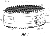
- an expandable corpectomy implant 100 includes a superior endplate 110 configured to contact the inferior endplate of a superior vertebral body and an inferior endplate 120 configured to contact the superior endplate of an inferior vertebral body.
- the superior and inferior endplates 110, 120 include teeth, serrations, ridges, or other anti-repulsion features to secure the endplates 110, 120 to the superior and inferior vertebral bodies.
- the superior and inferior endplates 110, 120 are detachable from the expandable corpectomy device 100 and can include a variety of modular geometries, including circular, ovular, kidney bean-shaped, etc., to conform to the adjacent vertebral bodies.
- the superior and inferior endplates 110, 120 can be flat, tapered, concave, or convex to further accommodate the anatomy of the adjacent vertebral endplates.
- the superior and inferior endplates 110, 120 can include brachytherapy seeds for treating tumors or may be coated or surface treated with beneficial agents.
- the superior and inferior endplates 110, 120 can be formed from rigid biocompatible material, such as titanium, stainless steel, or polymers such as PEEK.
- the superior and inferior endplates 110, 120 can be formed from conformable material to enable the superior and inferior endplates 110, 120 to conform to the anatomical shape of the adjacent vertebral endplates.
- an expansion bladder 130 that, in a further example, is divided into an inner chamber 140 and an outer chamber 150 is coupled to the superior and inferior endplates 110, 120 and extends therebetween.
- the outer chamber 150 in an example, is concentrically disposed about the inner chamber 140.
- the expansion bladder 130 can be divided into the isolated inner and outer chambers 140, 150 or a pair of expansion bladders can be used to form the inner and outer chambers 140, 150.
- the expansion bladder 130 can be coupled to the endplates 110, 120 using a mechanical or chemical bond or a combination of both that is capable of withstanding the expansion pressures required and the normal operating conditions of the implant 100.
- the endplates 110, 120 include annular undercut grooves corresponding to the interface between the walls of the bladder 130 and the endplates 110, 120 such that the bladder 130 can be injection molded in a way that the walls of the bladder 130 fill into the grooves inherent on the endplates 110, 120.
- the expansion bladder 130 can be formed from a variety of biocompatible elastomeric or non-elastic materials such as medical grade balloon material.
- the expansion bladder 130 is formed from a material having an expansion bias, such that the bladder expands more readily in a first direction than in other directions.
- the walls of the expansion bladder 130 that form the inner chamber 140 and/or the outer chamber 150 can be reinforced with one or more annular rings or coils to provide enhanced hoop strength.
- An injection port 160 in an example, is disposed through the inferior endplate 120, as shown best in FIGS. 4A, 4B , and 5A-5C , and is in fluid communication with both the inner chamber 140 and the outer chamber 150.
- the injection port 160 is divided into two channels 160A, 160B for fluid introduction, a first channel 160A configured for introducing expansion medium into the outer chamber 150 and a second channel 160B for introducing expansion medium into the inner chamber 140.
- the injection port 160 is disposed through the superior endplate 110.
- an access channel is provided to the spine and a portion of a damaged or diseased vertebral body in need of replacement is removed.
- the implant 100 in a collapsed configuration, is coupled to an insertion instrument and implanted in the space left by the removed portion of the diseased or damaged vertebral body.
- a pressured fluid such as saline, or air is temporarily injected or pumped into the outer chamber 150 by coupling a fill material introducer to the injection port 160.
- a second fill material introducer is coupled to the injection port 160 and the inner chamber 140 is filled with a permanent structural support material, such as PMMA, for instance, that is capable of being introduced in a fluid state and curing to a solid state to create a permanent, structural load bearing form.
- a permanent structural support material such as PMMA, for instance, that is capable of being introduced in a fluid state and curing to a solid state to create a permanent, structural load bearing form.
- the permanent structural support material cures within the inner chamber 140, the temporary pressurized fluid or air housed within the outer chamber 150 is evacuated and a rigid, expanded implant 100 remains.
- the permanent structural support material can incorporate bone graft, brachytherapy seeds, antibiotic, radiotherapeutic, or chemotherapeutic substances. The access channel is then sealed and the wound closed.
- the outer chamber 150 can be provisionally expanded and collapsed numerous times before committing to a final configuration or height for the implant 100, allowing a surgeon to optimize the size or expanded height of the implant 100 before introducing the permanent structural support material to the inner chamber 140.
- the containment of the permanent structural support material within the inner chamber 140 isolates the permanent structural support material from the surrounding anatomy.
- the temporary fluid contained within the outer chamber 150 can serve as a thermal insulator, protecting the nearby sensitive anatomical structures from the increased temperatures associated with any exothermic reactions that may occur during the curing of the permanent structural support material within the inner chamber 140.
- the temporary expansion fluid can be introduced to the inner chamber 140 and the permanent structural support material can be introduced to the outer chamber 150.
- an empty inner chamber 140 is left that, in various examples, can be filled with bone graft, brachytherapy seeds, or antibiotic, radiotherapeutic, or chemotherapeutic substances.
- the implant 100 is not limited to inclusion of the inner and outer chambers 140, 150 and, in some examples, the implant 100 can include a plurality of outer chambers and/or a plurality of inner chambers.
- the walls of the inner chamber 140 and/or the outer chamber 150 can be formed from materials of varying permeability to enable various beneficial substances to leach out of the implant 100 and into the surrounding anatomy postoperatively.
- the walls of the expansion bladder 130 can feature mechanical expansion mechanism(s), such as a telescopic, accordion-like, extension spring-like, etc., mechanism, as opposed to or in addition to the elastomeric material.
- mechanical expansion mechanism(s) such as a telescopic, accordion-like, extension spring-like, etc., mechanism, as opposed to or in addition to the elastomeric material.
- the implant 100 includes two separate injection ports 160 to communicate with the inner chamber 140 and the outer chamber 150 separately.
- the superior and inferior endplates 110, 120 each include one injection port 160, with the injection port 160 of one of the superior and inferior endplates 110, 120 in communication with one of the inner and outer chambers 140, 150, and the injection port 160 of the other of the superior and inferior endplates 110, 120 in communication with the other of the inner and outer chambers 140, 150.
- one of the superior and inferior endplates 110, 120 includes two injection ports 160, with one injection port 160 in communication with the inner chamber 140, and the other injection port 160 in communication with the outer chamber 150.
- both injection ports can be disposed adjacent one another on either the superior endplate 110 or the inferior endplate 120.
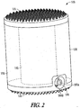
- an expandable corpectomy device 200 that includes an annular superior endplate 210 and an annular inferior endplate 220 that are similar in design and function to the example superior and inferior endplates 110, 120, with the exception that an axial bore 240 is provided through one or both of the superior and inferior endplates 210, 220.
- the expandable corpectomy device 200 includes an expansion bladder 230 that includes a single outer chamber 250.
- the expansion bladder 230 forms the outer chamber, which includes an annular geometry, such that the axial bore 240 is provided through the height of the implant 200.
- the expandable corpectomy device 200 in a further example, includes an injection port 260 that is in communication with the interior of the outer chamber 250 as well as the axial bore 240.
- the expandable corpectomy device 200 is inserted in a collapsed configuration into the space left by the removed portion of the diseased or damaged vertebral body, as described above.
- Pressured fluid such as saline or air is temporarily injected or pumped into the outer chamber 250 by coupling a fill material introducer to the injection port 260 and the superior and inferior endplates 210, 220 are distracted until a desired amount of height characterizes the implant 200.
- permanent structural support material is then introduced via the injection port to the axial bore 240, the permanent structural support material coming into direct contact with the inferior endplate of the superior remaining vertebral body and the superior endplate of the inferior remaining vertebral body.
- the temporary expansion fluid is evacuated from the outer chamber 250.
- the implant 200 can include more than one outer chamber.
- the inner chamber is replaced with an axial bore for permitting fusion through the assembly, such that temporary fluid can be injected into some of the outer chambers and structural support material can be injected into the remaining outer chamber(s).
- two separate expansion bladders can be used to form the inner chamber 140 and the outer chamber 150.
- the implant 100 or the implant 200 can be modified slightly to provide an expandable interbody spacer implant.
- implants can include various combinations and/or configurations of chambers.
- FIG. 6 shows an example of an expandable corpectomy device 600.
- the implant 600 can include one or more features and/or one or more properties similar to those included with the implant examples discussed above.
- the implant 600 includes a first endplate (broken away in FIG. 6 ) configured to contact a first vertebral body and a second endplate 620 configured to contact a second vertebral body.
- the first endplate and the second endplate 620 include teeth, serrations, ridges, or other anti-repulsion features to secure the first endplate and the second endplate 620 to the respective vertebral bodies.
- the implant 600 includes an expansion bladder 630.
- the expansion bladder 630 includes two first chambers 640 and a second chamber 650.
- the first chambers 640 are disposed within or otherwise surrounded by the second chamber 650.
- the expansion bladder 630 of the implant 600 includes more or fewer than two first chambers and/or more than one second bladder depending upon the application of the implant 600, the patient, the insertion location of the implant 600, or other relevant factors.
- the first chambers 640 are shown as substantially circular in cross section and the second chamber 650 is shown as substantially kidney-shaped in cross section, it is noted that the first and second chambers 640, 650 can include shapes other than those that are shown in FIG. 6 , again depending upon the application of the implant 600, the patient, the insertion location of the implant 600, or other relevant factors.
- An injection port 660 in an example, is disposed through the second endplate 620 and is in fluid communication with both the first chambers 640 and the second chamber 650.
- the injection port 660 is divided into two channels 660A, 660B for fluid introduction, with a first channel 660A configured for introducing expansion medium into the second chamber 650 and a second channel 660B for introducing expansion medium into the first chambers 640.
- the second channel 660B branches off to each of the first chambers 640 to allow for introduction of expansion medium into each of the first chambers 640.
- the injection port 660 is disposed through the first endplate.
- a pressured fluid such as saline, or air is temporarily injected or pumped into the second chamber 650 by coupling a fill material introducer to the injection port 660.
- Introduction of the temporary pressurized fluid or air to the second chamber 650 via the injection port 660 forces the height of the implant 600 to expand and the first endplate and the second endplate 620 to be distracted from one another until they bear against and impart a desired amount of distraction between the remaining vertebral bodies, thereby providing provisional anterior column support, distraction, and/or restoration of proper spinal alignment.
- a second fill material introducer is coupled to the injection port 660, and the first chambers 640 are filled with a permanent structural support material, such as PMMA, for instance, that is capable of being introduced in a fluid state and curing to a solid state to create a permanent, structural load bearing form.
- a permanent structural support material such as PMMA, for instance
- the temporary pressurized fluid or air housed within the second chamber 650 is evacuated and a rigid, expanded implant 600 remains.
- the permanent structural support material can incorporate bone graft, brachytherapy seeds, antibiotic, radiotherapeutic, or chemotherapeutic substances.
- the access channel is then sealed and the wound closed.
- the first chambers 640 can be filled with the temporary pressurized fluid or air and the second chamber 650 can be filled with the permanent structural support material.
- FIG. 7 shows an expandable corpectomy device 700.
- the implant 700 can include one or more features and/or one or more properties similar to those included with the implant examples discussed above.
- the implant 700 includes a first endplate (broken away in FIG. 7 ) configured to contact a first vertebral body and a second endplate 720 configured to contact a second vertebral body.
- the first endplate and the second endplate 720 include teeth, serrations, ridges, or other anti-repulsion features to secure the first endplate and the second endplate 720 to the respective vertebral bodies.
- the implant 700 includes expansion bladders 730. As shown in FIG. 7 , the implant 700 includes two expansion bladders 730, each including a first chamber 740 and a second chamber 750. In an example, each first chamber 740 is disposed within or otherwise surrounded by each second chamber 750. It is contemplated that, in other examples, the implant 700 includes more than two expansion bladders 730 depending upon the application of the implant 700, the patient, the insertion location of the implant 700, or other relevant factors. Although the first chambers 740 are shown as substantially circular in cross section and the second chambers 750 are shown as substantially annular in cross section, it is noted that the first and second chambers 740, 750 can include shapes other than those that are shown in FIG. 7 , again depending upon the application of the implant 700, the patient, the insertion location of the implant 700, or other relevant factors.
- An injection port 760 in an example, is disposed through the second endplate 720 and is in fluid communication with both the first chambers 740 and the second chambers 750.
- the injection port 760 is divided into two channels 760A, 760B for fluid introduction, with a first channel 760A configured for introducing expansion medium into the second chambers 750 and a second channel 760B for introducing expansion medium into the first chambers 740.
- the second channel 760B branches off to each of the first chambers 740 to allow for introduction of expansion medium into each of the first chambers 740
- the first channel 760A branches off to each of the second chambers 750 to allow for introduction of expansion medium into each of the second chambers 750.
- the injection port 760 is disposed through the first endplate.
- a pressured fluid such as saline, or air is temporarily injected or pumped into the second chambers 750 by coupling a fill material introducer to the injection port 760.
- Introduction of the temporary pressurized fluid or air to the second chambers 750 via the injection port 760 forces the height of the implant 700 to expand and the first endplate and the second endplate 720 to be distracted from one another until they bear against and impart a desired amount of distraction between the remaining vertebral bodies, thereby providing provisional anterior column support, distraction, and/or restoration of proper spinal alignment.
- a second fill material introducer is coupled to the injection port 760, and the first chambers 740 are filled with a permanent structural support material, such as PMMA, for instance, that is capable of being introduced in a fluid state and curing to a solid state to create a permanent, structural load bearing form.
- a permanent structural support material such as PMMA, for instance
- the temporary pressurized fluid or air housed within the second chambers 750 is evacuated and a rigid, expanded implant 700 remains.
- the permanent structural support material can incorporate bone graft, brachytherapy seeds, antibiotic, radiotherapeutic, or chemotherapeutic substances.
- the access channel is then sealed and the wound closed.
- the first chambers 740 can be filled with the temporary pressurized fluid or air and the second chambers 750 can be filled with the permanent structural support material.
- FIG. 8 shows an expandable corpectomy device 800.
- the implant 800 can include one or more features and/or one or more properties similar to those included with the implant examples discussed above.
- the implant 800 includes a first endplate (broken away in FIG. 8 ) configured to contact a first vertebral body and a second endplate 820 configured to contact a second vertebral body.
- the first endplate and the second endplate 820 include teeth, serrations, ridges, or other anti-repulsion features to secure the first endplate and the second endplate 820 to the respective vertebral bodies.
- the implant 800 includes an expansion bladder group 830. As shown in FIG. 8 , the expansion bladder group 830 includes two first chambers 840 and two second chambers 850. In an example, the first and second chambers 840, 850 are arranged in a two-by-two array with each first chamber 840 disposed at diagonally opposite corners of the array and each second chamber 850 disposed at the other corners of the array. In other examples, other arrangements of the first and second chambers 840, 850 are contemplated. It is further contemplated that, in other examples, the implant 800 includes more or less than two first chambers 840 and more or less than two second chambers 850 depending upon the application of the implant 800, the patient, the insertion location of the implant 800, or other relevant factors.
- first and second chambers 840, 850 are shown as substantially circular in cross section, it is noted that the first and second chambers 840, 850 can include shapes other than those that are shown in FIG. 8 , again depending upon the application of the implant 800, the patient, the insertion location of the implant 800, or other relevant factors.
- a first injection port 860A in an example, is disposed through the second endplate 820 and is in fluid communication with the second chambers 850, and a second injection port 860B is disposed through the second endplate 820 and is in fluid communication with the first chambers 840.
- the first injection port 860A is configured for introducing expansion medium into the second chambers 850
- the second injection port 860B is configured for introducing expansion medium into the first chambers 840.
- the second injection port 860B branches off to each of the first chambers 840 to allow for introduction of expansion medium into each of the first chambers 840
- the first injection port 860A branches off to each of the second chambers 850 to allow for introduction of expansion medium into each of the second chambers 850.
- the first and second injection ports 860A, 860B are disposed through the first endplate.
- a pressured fluid such as saline, or air is temporarily injected or pumped into the second chambers 850 by coupling a fill material introducer to the first injection port 860A.
- Introduction of the temporary pressurized fluid or air to the second chambers 850 via the first injection port 860A forces the height of the implant 800 to expand and the first endplate and the second endplate 820 to be distracted from one another until they bear against and impart a desired amount of distraction between the remaining vertebral bodies, thereby providing provisional anterior column support, distraction, and/or restoration of proper spinal alignment.
- a second fill material introducer is coupled to the second injection port 860B, and the first chambers 840 are filled with a permanent structural support material, such as PMMA, for instance, that is capable of being introduced in a fluid state and curing to a solid state to create a permanent, structural load bearing form.
- a permanent structural support material such as PMMA, for instance
- the temporary pressurized fluid or air housed within the second chambers 850 is evacuated and a rigid, expanded implant 800 remains.
- the permanent structural support material can incorporate bone graft, brachytherapy seeds, antibiotic, radiotherapeutic, or chemotherapeutic substances.
- the access channel is then sealed and the wound closed.
- the first chambers 840 can be filled with the temporary pressurized fluid or air and the second chambers 850 can be filled with the permanent structural support material.
Landscapes
- Health & Medical Sciences (AREA)
- Engineering & Computer Science (AREA)
- Biomedical Technology (AREA)
- Orthopedic Medicine & Surgery (AREA)
- Life Sciences & Earth Sciences (AREA)
- Animal Behavior & Ethology (AREA)
- Neurology (AREA)
- Veterinary Medicine (AREA)
- Public Health (AREA)
- General Health & Medical Sciences (AREA)
- Heart & Thoracic Surgery (AREA)
- Oral & Maxillofacial Surgery (AREA)
- Vascular Medicine (AREA)
- Transplantation (AREA)
- Cardiology (AREA)
- Surgery (AREA)
- Dermatology (AREA)
- Chemical & Material Sciences (AREA)
- Hematology (AREA)
- Medicinal Chemistry (AREA)
- Epidemiology (AREA)
- Nuclear Medicine, Radiotherapy & Molecular Imaging (AREA)
- Anesthesiology (AREA)
- Medical Informatics (AREA)
- Molecular Biology (AREA)
- Prostheses (AREA)
- Surgical Instruments (AREA)
Description
- This patent document pertains generally to orthopedics. More particularly, but not by way of limitation, this patent document pertains to a system, apparatus, and method for vertebral body replacement for the spine.
- Vertebral body replacement devices are indicated to provide anterior column support following a corpectomy, vertebrectomy, or spondylectomy as a result of trauma to the spine, removal of tumor material from the spinal column, or to correct spinal deformity. Surgeons typically utilize a number of different devices to provide this anterior column support, including structural bone struts made from auto- or allograft tissue, structural titanium mesh cages, expandable titanium devices, and makeshift constructs using polymethylmethacrylate (PMMA) cement and other common surgical devices, such as chest tubes, Steinmann pins, bone screws, etc., to reinforce and/or contain the cement.
- In cases in which it is desirable to address the patient's pathology from a posterior or posterolateral approach, the patient's neurological structures, such as the spinal cord, cauda equina, and exiting nerve roots, limit access to the corpectomy defect, limiting the use of many of the currently available devices or forcing the surgeon to use an implant size or configuration that is less than optimal. In such cases, surgeons often opt to use PMMA to fill the defect size since it can be injected through a narrow channel and can easily conform to the individual patient's anatomy. Often, the PMMA is supplemented with another device to reinforce and/or contain the cement. However, cement constructs are difficult to revise, the PMMA allows a limited working time window, and the PMMA undergoes an exothermic curing reaction that can damage surrounding tissues. Further, there is little or no fusion potential when using these constructs and their application is typically limited to patients with a low life expectancy, e.g., tumor patients.
-
US 2007/0173940 A1 discloses a device for facilitating bone fusion of two vertebrae. The device comprises two expandable chambers, wherein one the chambers surrounds the other chamber. The chambers can be filled with material via injection ports that extends from the outer wall of the implant. The inner chamber is closed and is filled e.g. with PMMA to distract the two vertebrae. The outer chamber is preferably open to the top and bottom surfaces and is filled with a material that promotes bone fusion of the adjacent vertebrae. -
US 2007/0233254 A1 discloses an implantable device for insertion between first and second vertebrae. Two endplates of the device are expanded by means of cylinder piston assemblies, which can be independently controlled by a hydraulic control device. The cylinder piston assemblies fluidly communicate with the hydraulic control device via hydraulic lines which are connected to the implant by means of an injection port in one of the endplates. The cylinders may be filled with a curable polymer, such as MMA. - An artificial intervertebral disc is disclosed in
US 6,984,246 B2 . A nucleus member is flexibly resiliently formed between two endplates. The nucleus is formed of outer and inner bellows forming two chambers, wherein a relatively hard outer cushioning filler is injected into the outer chamber, whereas a relatively soft cushioning filler is injected into the inner chamber of the nucleus. -
US 2005/0216084 A1 discloses a modular hydraulic spinal intervertebral prosthetic device for insertion between two vertebrae. Between two endplates a bellows assembly is disposed, which may be filled with a fluid via fluid conduits in one of the endplates, such that the bellows provides damping properties. - The implantable device disclosed in
FR 2723841 -
US 2008/0058931 A1 discloses an implant for insertion between two vertebral bodies. Two end portions are slidably connected to one another, wherein an inflatable balloon-like member is disposed between the end portions. The implant is expanded upon filling the balloon with a fluid. The balloon may be filled with a curable polymer, such as PMMA. - In the drawings, like numerals describe similar components throughout the several views. Like numerals having different letter suffixes represent different instances of similar components. The drawings illustrate generally, by way of example, but not by way of limitation, various embodiments discussed in the present document.
-
FIG. 1 illustrates a front perspective view of an expandable corpectomy implant in accordance with an example of the present invention in a collapsed configuration; -
FIG. 2 illustrates a front perspective view of the expandable corpectomy implant ofFIG. 1 in an expanded configuration; -
FIG. 3 illustrates a top perspective view of an expandable corpectomy implant in accordance with an example of the present invention; -
FIGS. 4A and 4B illustrate a front elevational view and a side cross-sectional view, respectively, of an inferior endplate of the expandable corpectomy implant ofFIG. 1 ; -
FIGS. 5A-5C illustrate a top perspective view, a bottom plan view, and a side cross-sectional view, respectively, of the inferior endplate of the expandable corpectomy implant ofFIG. 1 ; -
FIG. 6 illustrates a top view of an expandable corpectomy implant in accordance with an example of the present invention, the implant shown with an endplate broken away for purposes of illustration; -
FIG. 7 illustrates a top view of an expandable corpectomy implant in accordance with an example of the present invention, the implant shown with an endplate broken away for purposes of illustration; and -
FIG. 8 illustrates a top view of an expandable corpectomy implant in accordance with an example of the present invention, the implant shown with an endplate broken away for purposes of illustration. - Certain terminology is used in the following description for convenience only and is not limiting. The words "right", "left", "lower", and "upper" designate directions in the drawings to which reference is made. The words "inwardly" or "distally" and "outwardly" or "proximally" refer to directions toward and away from, respectively, the geometric center of the low insertion profile vertebral body replacement implant, related instruments and related parts thereof. The words, "anterior", "posterior", "superior," "inferior" and related words and/or phrases designate preferred positions and orientations in the human body to which reference is made and are not meant to be limiting. The terminology includes the above-listed words, derivatives thereof and words of similar import.
- The present inventor has recognized, among other things, that limited access to a corpectomy defect from a posterior or posterolateral approach presents problems during vertebral body replacement surgical procedures. The present inventor has further recognized that there exists an unmet need for a corpectomy implant configured for posterior or posterolateral approach that can be introduced in a minimally invasive, tissue-sparing manner, and provide stable structural support.
- This patent document describes, among other things, apparatuses, systems, and methods for vertebral body replacement for the spine. In various examples, an implantable device is configured to be inserted between a first vertebral body and a second vertebral body. The implantable device includes a first endplate configured to contact the first vertebral body. A second endplate is configured to contact the second vertebral body. An expansion bladder is disposed between and coupled to the first endplate and the second endplate. The expansion bladder includes a first chamber and a second chamber. The first chamber and the second chamber are sealed from fluid communication with one another. An injection port is disposed through one of the first endplate or second endplate. The injection port includes a first channel in fluid communication with the first chamber and a second channel in fluid communication with the second chamber. The second chamber surrounds the first chamber.
- In Example 1, an implantable device is configured for insertion between a first vertebral body and a second vertebral body. The implantable device comprises a first endplate configured to contact the first vertebral body. A second endplate is configured to contact the second vertebral body. An expansion bladder is disposed between and coupled to the first endplate and the second endplate. The expansion bladder includes a first chamber and a second chamber. The first chamber and the second chamber are sealed from fluid communication with one another. An injection port is disposed through one of the first endplate or second endplate. The injection port includes a first channel in fluid communication with the first chamber and a second channel in fluid communication with the second chamber.
- In Example 2, the implantable device of Example 1 is configured such that the second chamber surrounds the first chamber.
- In Example 3, the implantable device of one or more of Examples 1-2 optionally is configured such that the second chamber is substantially concentrically disposed around the first chamber.
- In Example 4, the implantable device of one or more of Examples 1-3 optionally is configured such that the expansion bladder is configured to expand with filling of at least one of the first and second chambers with a material. Expansion of the expansion bladder causes the first and second endplates to move apart from each other.
- In Example 5, the implantable device of Example 4 optionally is configured such that at least one of the first and second chambers is configured to be at least partially filled with saline.
- In Example 6, the implantable device of one or more of Examples 4-5 optionally is configured such that at least one of the first and second chambers is configured to be at least partially filled with air.
- In Example 7, the implantable device of one or more of Examples 4-6 optionally is configured such that at least one of the first and second chambers is configured to be at least partially filled with a structural support material.
- In Example 8, the implantable device of Example 7 optionally is configured such that the structural support material includes polymethylmethacrylate.
- In Example 9, the implantable device of one or more of Examples 1-8 optionally is configured such that at least one of the first and second endplates is annular.
- In Example 10, the implantable device of Example 9 optionally is configured such that both of the first and second endplates are annular.
- In Example 11, the implantable device of Example 10 optionally is configured such that the first chamber of the expansion bladder is disposed at open areas of the annular first and second endplates.
- In Example 12, the implantable device of one or more of Examples 1-11 optionally is configured such that the expansion bladder includes two or more first chambers.
- In Example 13, the implantable device of one or more of Examples 1-12 optionally is configured such that the expansion bladder includes two or more second chambers.
- In Example 14, a vertebral body replacement system comprises an implantable device for insertion between a first vertebral body and a second vertebral body. The implantable device comprises a first endplate configured to contact the first vertebral body. A second endplate is configured to contact the second vertebral body. An expansion bladder is disposed between and coupled to the first endplate and the second endplate. The expansion bladder includes a first chamber and a second chamber. The first chamber and the second chamber are sealed from fluid communication with one another. An injection port is disposed through one of the first endplate or second endplate. The injection port includes a first channel in fluid communication with the first chamber and a second channel in fluid communication with the second chamber. A fill material introducer is configured to fluidly communicate with at least one of the first and second channels to at least partially fill at least one of the first and second chambers with a material.
- In Example 15, the vertebral body replacement system of Example 14 optionally is configured such that the fill material introducer includes a first fill material introducer configured to fluidly communicate with the first channel to at least partially fill the first chamber with a first material and a second fill material introducer configured to fluidly communicate with the second channel to at least partially fill the second chamber with a second material.
- In Example 16, the vertebral body replacement system of Example 15 optionally is configured such that the first material includes an expansion fluid and the second material includes a structural support material.
- In Example 17, the vertebral body replacement system of one or more of Examples 14-16 is configured such that the second chamber surrounds the first chamber.
- In Example 18, the vertebral body replacement system of one or more of Examples 14-17 optionally is configured such that the second chamber is substantially concentrically disposed around the first chamber.
- In Example 19, the vertebral body replacement system of one or more of Examples 14-18 optionally is configured such that the expansion bladder is configured to expand with filling of at least one of the first and second chambers with the material. Expansion of the expansion bladder causes the first and second endplates to move apart from each other.
- In Example 20, a method of vertebral body replacement comprises inserting an implantable device between a first vertebral body and a second vertebral body. The implantable device includes a first endplate configured to contact the first vertebral body, a second endplate configured to contact the second vertebral body, and an expansion bladder disposed between and coupled to the first endplate and the second endplate. The expansion bladder includes a first chamber and a second chamber. The first chamber and the second chamber are sealed from fluid communication with one another. An expansion fluid is introduced into the first chamber of the expansion bladder to separate the first and second endplates of the implantable device to achieve a final height of the implantable device. A structural support material is introduced into the second chamber of the expansion bladder to maintain the final height of the implantable device.
- In Example 21, the method of Example 20 optionally comprises evacuating the expansion fluid from the first chamber after introducing the structural support material into the second chamber of the expansion bladder.
- In Example 22, the method of Example 21 optionally comprises introducing a substance into the first chamber after evacuation of the expansion fluid.
- In Example 23, the method of Example 22 optionally is configured such that introducing the substance into the first chamber includes introducing a therapeutic substance into the first chamber.
- In Example 24, the method of one or more of Examples 20-23 optionally is configured such that introducing the expansion fluid includes separating the first and second endplates of the implantable device to cause the first endplate to contact the first vertebral body and to cause the second endplate to contact the second vertebral body.
- In Example 25, a method is configured for treatment of a spine including a damaged or diseased vertebral body disposed between first and second vertebral bodies. The method comprises providing an access channel to the spine. The damaged or diseased vertebral body is removed. An implantable device is inserted, through the access channel, between the first vertebral body and the second vertebral body. The implantable device includes a first endplate configured to contact the first vertebral body. A second endplate is configured to contact the second vertebral body. An expansion bladder is disposed between and coupled to the first endplate and the second endplate. The expansion bladder includes a first chamber and a second chamber. The first chamber and the second chamber are sealed from fluid communication with one another. An expansion fluid is introduced into the first chamber of the expansion bladder to separate the first and second endplates of the implantable device to achieve a final height of the implantable device. The first endplate is in contact with the first vertebral body and the second endplate is in contact with the second vertebral body. A structural support material is introduced into the second chamber of the expansion bladder to maintain the final height of the implantable device.
- In Example 26, the method of Example 25 optionally comprises evacuating the expansion fluid from the first chamber after introducing the structural support material into the second chamber of the expansion bladder.
- In Example 27, the method of Example 26 optionally comprises introducing a substance into the first chamber after evacuation of the expansion fluid.
- In Example 28, the method of Example 27 optionally is configured such that introducing the substance into the first chamber includes introducing a therapeutic substance into the first chamber.
- In Example 29, the method of one or more of Examples 25-28 optionally comprises sealing the access channel following insertion of the implantable device.
- In Example 30, the method of one or more of Examples 25-29 optionally is configured such that inserting the implantable device includes inserting the implantable device with an initial height of the implantable device that is less than the final height.
- Referring to
FIGS. 1 and2 , in an example, anexpandable corpectomy implant 100 includes asuperior endplate 110 configured to contact the inferior endplate of a superior vertebral body and aninferior endplate 120 configured to contact the superior endplate of an inferior vertebral body. In various examples, the superior andinferior endplates endplates inferior endplates expandable corpectomy device 100 and can include a variety of modular geometries, including circular, ovular, kidney bean-shaped, etc., to conform to the adjacent vertebral bodies. The superior andinferior endplates inferior endplates inferior endplates inferior endplates inferior endplates - In an example, an
expansion bladder 130 that, in a further example, is divided into aninner chamber 140 and anouter chamber 150 is coupled to the superior andinferior endplates outer chamber 150, in an example, is concentrically disposed about theinner chamber 140. Theexpansion bladder 130 can be divided into the isolated inner andouter chambers outer chambers expansion bladder 130 can be coupled to theendplates implant 100. Theendplates bladder 130 and theendplates bladder 130 can be injection molded in a way that the walls of thebladder 130 fill into the grooves inherent on theendplates expansion bladder 130 can be formed from a variety of biocompatible elastomeric or non-elastic materials such as medical grade balloon material. In an example, theexpansion bladder 130 is formed from a material having an expansion bias, such that the bladder expands more readily in a first direction than in other directions. The walls of theexpansion bladder 130 that form theinner chamber 140 and/or theouter chamber 150 can be reinforced with one or more annular rings or coils to provide enhanced hoop strength. - An
injection port 160, in an example, is disposed through theinferior endplate 120, as shown best inFIGS. 4A, 4B , and5A-5C , and is in fluid communication with both theinner chamber 140 and theouter chamber 150. In a further example, theinjection port 160 is divided into twochannels first channel 160A configured for introducing expansion medium into theouter chamber 150 and asecond channel 160B for introducing expansion medium into theinner chamber 140. In another example, theinjection port 160 is disposed through thesuperior endplate 110. - In operation and in continuing reference to
FIGS. 1 and2 , in an example, an access channel is provided to the spine and a portion of a damaged or diseased vertebral body in need of replacement is removed. Theimplant 100, in a collapsed configuration, is coupled to an insertion instrument and implanted in the space left by the removed portion of the diseased or damaged vertebral body. Once theimplant 100 is determined to be optimally positioned with respect to the vertebral bodies, a pressured fluid, such as saline, or air is temporarily injected or pumped into theouter chamber 150 by coupling a fill material introducer to theinjection port 160. Introduction of the temporary pressurized fluid or air to theouter chamber 150 via theinjection port 160 forces the height of theimplant 100 to expand and the superior andinferior endplates outer chamber 150, in an example, a second fill material introducer is coupled to theinjection port 160 and theinner chamber 140 is filled with a permanent structural support material, such as PMMA, for instance, that is capable of being introduced in a fluid state and curing to a solid state to create a permanent, structural load bearing form. Once the permanent structural support material cures within theinner chamber 140, the temporary pressurized fluid or air housed within theouter chamber 150 is evacuated and a rigid, expandedimplant 100 remains. In various examples, the permanent structural support material can incorporate bone graft, brachytherapy seeds, antibiotic, radiotherapeutic, or chemotherapeutic substances. The access channel is then sealed and the wound closed. - In an example, the
outer chamber 150 can be provisionally expanded and collapsed numerous times before committing to a final configuration or height for theimplant 100, allowing a surgeon to optimize the size or expanded height of theimplant 100 before introducing the permanent structural support material to theinner chamber 140. In a further example, the containment of the permanent structural support material within theinner chamber 140 isolates the permanent structural support material from the surrounding anatomy. In a further example, the temporary fluid contained within theouter chamber 150 can serve as a thermal insulator, protecting the nearby sensitive anatomical structures from the increased temperatures associated with any exothermic reactions that may occur during the curing of the permanent structural support material within theinner chamber 140. - In an example, the temporary expansion fluid can be introduced to the
inner chamber 140 and the permanent structural support material can be introduced to theouter chamber 150. Upon curing of the permanent structural material within theouter chamber 150 and the evacuation of the temporary expansion fluid within theinner chamber 140, an emptyinner chamber 140 is left that, in various examples, can be filled with bone graft, brachytherapy seeds, or antibiotic, radiotherapeutic, or chemotherapeutic substances. Theimplant 100 is not limited to inclusion of the inner andouter chambers implant 100 can include a plurality of outer chambers and/or a plurality of inner chambers. - In various examples, the walls of the
inner chamber 140 and/or theouter chamber 150 can be formed from materials of varying permeability to enable various beneficial substances to leach out of theimplant 100 and into the surrounding anatomy postoperatively. - In further examples, the walls of the
expansion bladder 130 can feature mechanical expansion mechanism(s), such as a telescopic, accordion-like, extension spring-like, etc., mechanism, as opposed to or in addition to the elastomeric material. - In an example, the
implant 100 includes twoseparate injection ports 160 to communicate with theinner chamber 140 and theouter chamber 150 separately. In an example, the superior andinferior endplates injection port 160, with theinjection port 160 of one of the superior andinferior endplates outer chambers injection port 160 of the other of the superior andinferior endplates outer chambers inferior endplates injection ports 160, with oneinjection port 160 in communication with theinner chamber 140, and theother injection port 160 in communication with theouter chamber 150. In a further example, both injection ports can be disposed adjacent one another on either thesuperior endplate 110 or theinferior endplate 120. - In another example, and in reference to
FIG. 3 , anexpandable corpectomy device 200 is provided that includes an annularsuperior endplate 210 and an annularinferior endplate 220 that are similar in design and function to the example superior andinferior endplates axial bore 240 is provided through one or both of the superior andinferior endplates expandable corpectomy device 200 includes anexpansion bladder 230 that includes a singleouter chamber 250. In an example, theexpansion bladder 230 forms the outer chamber, which includes an annular geometry, such that theaxial bore 240 is provided through the height of theimplant 200. Theexpandable corpectomy device 200, in a further example, includes aninjection port 260 that is in communication with the interior of theouter chamber 250 as well as theaxial bore 240. - In operation and in continuing reference to
FIG. 3 , in an example, theexpandable corpectomy device 200 is inserted in a collapsed configuration into the space left by the removed portion of the diseased or damaged vertebral body, as described above. Pressured fluid, such as saline or air is temporarily injected or pumped into theouter chamber 250 by coupling a fill material introducer to theinjection port 260 and the superior andinferior endplates implant 200. In an example, permanent structural support material is then introduced via the injection port to theaxial bore 240, the permanent structural support material coming into direct contact with the inferior endplate of the superior remaining vertebral body and the superior endplate of the inferior remaining vertebral body. Upon curing of the permanent structural support material within theaxial bore 240, the temporary expansion fluid is evacuated from theouter chamber 250. - In various examples, the
implant 200 can include more than one outer chamber. In a further example, the inner chamber is replaced with an axial bore for permitting fusion through the assembly, such that temporary fluid can be injected into some of the outer chambers and structural support material can be injected into the remaining outer chamber(s). - In an example, two separate expansion bladders can be used to form the
inner chamber 140 and theouter chamber 150. In an example, theimplant 100 or theimplant 200 can be modified slightly to provide an expandable interbody spacer implant. - Referring to
FIGS. 6-8 , in various examples, implants can include various combinations and/or configurations of chambers. For instance,FIG. 6 shows an example of anexpandable corpectomy device 600. It is noted that, in various examples, in addition to the features and properties described below, theimplant 600 can include one or more features and/or one or more properties similar to those included with the implant examples discussed above. In an example, theimplant 600 includes a first endplate (broken away inFIG. 6 ) configured to contact a first vertebral body and asecond endplate 620 configured to contact a second vertebral body. In various examples, the first endplate and thesecond endplate 620 include teeth, serrations, ridges, or other anti-repulsion features to secure the first endplate and thesecond endplate 620 to the respective vertebral bodies. - In an example, the
implant 600 includes anexpansion bladder 630. As shown inFIG. 6 , theexpansion bladder 630 includes twofirst chambers 640 and asecond chamber 650. In an example, thefirst chambers 640 are disposed within or otherwise surrounded by thesecond chamber 650. It is contemplated that, in other examples, theexpansion bladder 630 of theimplant 600 includes more or fewer than two first chambers and/or more than one second bladder depending upon the application of theimplant 600, the patient, the insertion location of theimplant 600, or other relevant factors. Although thefirst chambers 640 are shown as substantially circular in cross section and thesecond chamber 650 is shown as substantially kidney-shaped in cross section, it is noted that the first andsecond chambers FIG. 6 , again depending upon the application of theimplant 600, the patient, the insertion location of theimplant 600, or other relevant factors. - An
injection port 660, in an example, is disposed through thesecond endplate 620 and is in fluid communication with both thefirst chambers 640 and thesecond chamber 650. In a further example, theinjection port 660 is divided into twochannels first channel 660A configured for introducing expansion medium into thesecond chamber 650 and asecond channel 660B for introducing expansion medium into thefirst chambers 640. In the example ofFIG. 6 , thesecond channel 660B branches off to each of thefirst chambers 640 to allow for introduction of expansion medium into each of thefirst chambers 640. In another example, theinjection port 660 is disposed through the first endplate. - In an example, once the
implant 600 is determined to be optimally positioned with respect to the vertebral bodies, a pressured fluid, such as saline, or air is temporarily injected or pumped into thesecond chamber 650 by coupling a fill material introducer to theinjection port 660. Introduction of the temporary pressurized fluid or air to thesecond chamber 650 via theinjection port 660 forces the height of theimplant 600 to expand and the first endplate and thesecond endplate 620 to be distracted from one another until they bear against and impart a desired amount of distraction between the remaining vertebral bodies, thereby providing provisional anterior column support, distraction, and/or restoration of proper spinal alignment. Once the desired implant height is achieved via the filling of thesecond chamber 650, in an example, a second fill material introducer is coupled to theinjection port 660, and thefirst chambers 640 are filled with a permanent structural support material, such as PMMA, for instance, that is capable of being introduced in a fluid state and curing to a solid state to create a permanent, structural load bearing form. Once the permanent structural support material cures within thefirst chambers 640, the temporary pressurized fluid or air housed within thesecond chamber 650 is evacuated and a rigid, expandedimplant 600 remains. In various examples, the permanent structural support material can incorporate bone graft, brachytherapy seeds, antibiotic, radiotherapeutic, or chemotherapeutic substances. The access channel is then sealed and the wound closed. In another example, thefirst chambers 640 can be filled with the temporary pressurized fluid or air and thesecond chamber 650 can be filled with the permanent structural support material. - In another example,
FIG. 7 shows anexpandable corpectomy device 700. It is noted that, in various examples, in addition to the features and properties described below, theimplant 700 can include one or more features and/or one or more properties similar to those included with the implant examples discussed above. In an example, theimplant 700 includes a first endplate (broken away inFIG. 7 ) configured to contact a first vertebral body and asecond endplate 720 configured to contact a second vertebral body. In various examples, the first endplate and thesecond endplate 720 include teeth, serrations, ridges, or other anti-repulsion features to secure the first endplate and thesecond endplate 720 to the respective vertebral bodies. - In an example, the
implant 700 includesexpansion bladders 730. As shown inFIG. 7 , theimplant 700 includes twoexpansion bladders 730, each including afirst chamber 740 and asecond chamber 750. In an example, eachfirst chamber 740 is disposed within or otherwise surrounded by eachsecond chamber 750. It is contemplated that, in other examples, theimplant 700 includes more than twoexpansion bladders 730 depending upon the application of theimplant 700, the patient, the insertion location of theimplant 700, or other relevant factors. Although thefirst chambers 740 are shown as substantially circular in cross section and thesecond chambers 750 are shown as substantially annular in cross section, it is noted that the first andsecond chambers FIG. 7 , again depending upon the application of theimplant 700, the patient, the insertion location of theimplant 700, or other relevant factors. - An
injection port 760, in an example, is disposed through thesecond endplate 720 and is in fluid communication with both thefirst chambers 740 and thesecond chambers 750. In a further example, theinjection port 760 is divided into twochannels first channel 760A configured for introducing expansion medium into thesecond chambers 750 and asecond channel 760B for introducing expansion medium into thefirst chambers 740. In the example ofFIG. 7 , thesecond channel 760B branches off to each of thefirst chambers 740 to allow for introduction of expansion medium into each of thefirst chambers 740, and thefirst channel 760A branches off to each of thesecond chambers 750 to allow for introduction of expansion medium into each of thesecond chambers 750. In another example, theinjection port 760 is disposed through the first endplate. - In an example, once the
implant 700 is determined to be optimally positioned with respect to the vertebral bodies, a pressured fluid, such as saline, or air is temporarily injected or pumped into thesecond chambers 750 by coupling a fill material introducer to theinjection port 760. Introduction of the temporary pressurized fluid or air to thesecond chambers 750 via theinjection port 760 forces the height of theimplant 700 to expand and the first endplate and thesecond endplate 720 to be distracted from one another until they bear against and impart a desired amount of distraction between the remaining vertebral bodies, thereby providing provisional anterior column support, distraction, and/or restoration of proper spinal alignment. Once the desired implant height is achieved via the filling of thesecond chambers 750, in an example, a second fill material introducer is coupled to theinjection port 760, and thefirst chambers 740 are filled with a permanent structural support material, such as PMMA, for instance, that is capable of being introduced in a fluid state and curing to a solid state to create a permanent, structural load bearing form. Once the permanent structural support material cures within thefirst chambers 740, the temporary pressurized fluid or air housed within thesecond chambers 750 is evacuated and a rigid, expandedimplant 700 remains. In various examples, the permanent structural support material can incorporate bone graft, brachytherapy seeds, antibiotic, radiotherapeutic, or chemotherapeutic substances. The access channel is then sealed and the wound closed. In another example, thefirst chambers 740 can be filled with the temporary pressurized fluid or air and thesecond chambers 750 can be filled with the permanent structural support material. - In another example,
FIG. 8 shows anexpandable corpectomy device 800. It is noted that, in various examples, in addition to the features and properties described below, theimplant 800 can include one or more features and/or one or more properties similar to those included with the implant examples discussed above. In an example, theimplant 800 includes a first endplate (broken away inFIG. 8 ) configured to contact a first vertebral body and asecond endplate 820 configured to contact a second vertebral body. In various examples, the first endplate and thesecond endplate 820 include teeth, serrations, ridges, or other anti-repulsion features to secure the first endplate and thesecond endplate 820 to the respective vertebral bodies. - In an example, the
implant 800 includes anexpansion bladder group 830. As shown inFIG. 8 , theexpansion bladder group 830 includes twofirst chambers 840 and twosecond chambers 850. In an example, the first andsecond chambers first chamber 840 disposed at diagonally opposite corners of the array and eachsecond chamber 850 disposed at the other corners of the array. In other examples, other arrangements of the first andsecond chambers implant 800 includes more or less than twofirst chambers 840 and more or less than twosecond chambers 850 depending upon the application of theimplant 800, the patient, the insertion location of theimplant 800, or other relevant factors. Although the first andsecond chambers second chambers FIG. 8 , again depending upon the application of theimplant 800, the patient, the insertion location of theimplant 800, or other relevant factors. - A
first injection port 860A, in an example, is disposed through thesecond endplate 820 and is in fluid communication with thesecond chambers 850, and asecond injection port 860B is disposed through thesecond endplate 820 and is in fluid communication with thefirst chambers 840. In a further example, thefirst injection port 860A is configured for introducing expansion medium into thesecond chambers 850, and thesecond injection port 860B is configured for introducing expansion medium into thefirst chambers 840. In the example ofFIG. 8 , thesecond injection port 860B branches off to each of thefirst chambers 840 to allow for introduction of expansion medium into each of thefirst chambers 840, and thefirst injection port 860A branches off to each of thesecond chambers 850 to allow for introduction of expansion medium into each of thesecond chambers 850. In another example, the first andsecond injection ports - In an example, once the
implant 800 is determined to be optimally positioned with respect to the vertebral bodies, a pressured fluid, such as saline, or air is temporarily injected or pumped into thesecond chambers 850 by coupling a fill material introducer to thefirst injection port 860A. Introduction of the temporary pressurized fluid or air to thesecond chambers 850 via thefirst injection port 860A forces the height of theimplant 800 to expand and the first endplate and thesecond endplate 820 to be distracted from one another until they bear against and impart a desired amount of distraction between the remaining vertebral bodies, thereby providing provisional anterior column support, distraction, and/or restoration of proper spinal alignment. Once the desired implant height is achieved via the filling of thesecond chambers 850, in an example, a second fill material introducer is coupled to thesecond injection port 860B, and thefirst chambers 840 are filled with a permanent structural support material, such as PMMA, for instance, that is capable of being introduced in a fluid state and curing to a solid state to create a permanent, structural load bearing form. Once the permanent structural support material cures within thefirst chambers 840, the temporary pressurized fluid or air housed within thesecond chambers 850 is evacuated and a rigid, expandedimplant 800 remains. In various examples, the permanent structural support material can incorporate bone graft, brachytherapy seeds, antibiotic, radiotherapeutic, or chemotherapeutic substances. The access channel is then sealed and the wound closed. In another example, thefirst chambers 840 can be filled with the temporary pressurized fluid or air and thesecond chambers 850 can be filled with the permanent structural support material. - It will be appreciated by those skilled in the art that changes could be made to the examples described above without departing from the broad inventive concept thereof. It is understood, therefore, that this invention is not limited to the particular examples disclosed, but it is intended to cover modifications within the scope of the present invention as defined by the appended claims.
- The above Detailed Description includes references to the accompanying drawings, which form a part of the Detailed Description. The drawings show, by way of illustration, specific embodiments in which the invention can be practiced. These embodiments are also referred to herein as "examples."
- In this document, the terms "a" or "an" are used, as is common in patent documents, to include one or more than one, independent of any other instances or usages of "at least one" or "one or more." In this document, the term "or" is used to refer to a nonexclusive or, such that "A or B" includes "A but not B," "B but not A," and "A and B," unless otherwise indicated. In the appended claims, the terms "including" and "in which" are used as the plain-English equivalents of the respective terms "comprising" and "wherein." Also, in the following claims, the terms "including" and "comprising" are open-ended, that is, a system, device, article, or process that includes elements in addition to those listed after such a term in a claim are still deemed to fall within the scope of that claim. Moreover, in the following claims, the terms "first," "second," and "third," etc. are used merely as labels, and are not intended to impose numerical requirements on their objects.
- The above description is intended to be illustrative, and not restrictive. For example, the above-described examples (or one or more features thereof) may be used in combination with each other. Other embodiments can be used, such as by one of ordinary skill in the art upon reviewing the above description. Also, in the above Detailed Description, various features may be grouped together to streamline the disclosure. This should not be interpreted as intending that an unclaimed disclosed feature is essential to any claim. Rather, inventive subject matter may lie in less than all features of a particular disclosed embodiment.
- The scope of the invention should be determined with reference to the appended claims, along with the full scope of equivalents to which such claims are entitled.
- The Abstract is provided to allow the reader to quickly ascertain the nature of the technical disclosure. It is submitted with the understanding that it will not be used to interpret or limit the scope or meaning of the claims.
Claims (15)
- An implantable device (100; 200; 600; 700) for insertion between a first vertebral body and a second vertebral body, the implantable device comprising:a first endplate (110; 210) configured to contact the first vertebral body;a second endplate (120; 220; 620; 720) configured to contact the second vertebral body;an expansion bladder (130; 230; 630; 730) disposed between and coupled to the first endplate (110; 210) and the second endplate (120; 220; 620; 720), the expansion bladder (130; 230; 630; 730) including a first chamber (140; 240; 640; 740) and a second chamber (150; 250; 650; 750), the first chamber (140; 240; 640; 740) and the second chamber (150; 250; 650; 750) being sealed from fluid communication with one another, wherein the second chamber (150; 250; 650; 750) surrounds the first chamber (140; 240; 640; 740); andan injection port (160; 260; 660; 760) including a first channel (160B; 660B, 760B) in fluid communication with the first chamber (140; 240; 640; 740) and a second channel (160A; 660A; 760A) in fluid communication with the second chamber (150; 250; 650; 750),characterized in that the injection port (160; 260; 660; 760) is disposed through one of the first endplate (110; 210) or second endplate (120; 220; 620; 720).
- The implantable device of claim 1, wherein the second chamber (150; 250; 750) is substantially concentrically disposed around the first chamber (140; 240; 740).
- The implantable device of claim 1 or 2, wherein the expansion bladder (130; 230; 630; 730) is configured to expand with filling of at least one of the first (140; 240; 640; 740) and second chambers (150; 250; 650; 750) with a material, wherein expansion of the expansion bladder (130; 230; 630; 730) causes the first (110; 210) and second endplates (120; 220; 620; 720) to move apart from each other.
- The implantable device of claim 3, wherein at least one of the first (140; 240; 640; 740) and second chambers (150; 250; 650; 750) is configured to be at least partially filled with saline.
- The implantable device of claim 3 or 4, wherein at least one of the first (140; 240; 640; 740) and second chambers (150; 250; 650; 750) is configured to be at least partially filled with air.
- The implantable device of any one of claims 3 to 5, wherein at least one of the first (140; 240; 640; 740) and second chambers (150; 250; 650; 750) is configured to be at least partially filled with a structural support material.
- The implantable device of claim 6, wherein the structural support material includes polymethylmethacrylate.
- The implantable device of any one of claims 1 to 7, wherein at least one of the first and second endplates (210, 220) is annular.
- The implantable device of claim 8, wherein both of the first and second endplates (210; 220) are annular.
- The implantable device of claim 8 or 9, wherein the first chamber (240) of the expansion bladder (230) is disposed at open areas of the annular first and second endplates (210; 220).
- The implantable device of any one of claims 1 to 10, wherein the expansion bladder (630; 730) includes two or more first chambers.
- The implantable device of any one of claims 1 to 11, wherein the expansion bladder (630; 730) includes two or more second chambers.
- A vertebral body replacement system comprising:an implantable device (100; 200; 600; 700) for insertion between a first vertebral body and a second vertebral body according to any one of claims 1 to 12; anda fill material introducer configured to fluidly communicate with at least one of the first (160B; 660B, 760B) and second channels (160A; 660A; 760A) to at least partially fill at least one of the first (140; 240; 640; 740) and second chambers (150; 250; 650; 750) with a material.
- The vertebral body replacement system of claim 13, wherein the fill material introducer includes a first fill material introducer configured to fluidly communicate with the first channel (160B; 660B, 760B) to at least partially fill the first chamber (140; 240; 640; 740) with a first material and a second fill material introducer configured to fluidly communicate with the second channel (160A; 660A; 760A) to at least partially fill the second chamber (150; 250; 650; 750) with a second material.
- The vertebral body replacement system of claim 14, wherein the first material includes an expansion fluid and the second material includes a structural support material.
Applications Claiming Priority (2)
| Application Number | Priority Date | Filing Date | Title |
|---|---|---|---|
| US14003808P | 2008-12-22 | 2008-12-22 | |
| PCT/US2009/006378 WO2010074704A1 (en) | 2008-12-22 | 2009-12-04 | Expandable vertebral body replacement device and method |
Publications (2)
| Publication Number | Publication Date |
|---|---|
| EP2376027A1 EP2376027A1 (en) | 2011-10-19 |
| EP2376027B1 true EP2376027B1 (en) | 2017-02-22 |
Family
ID=42041759
Family Applications (1)
| Application Number | Title | Priority Date | Filing Date |
|---|---|---|---|
| EP09775378.4A Active EP2376027B1 (en) | 2008-12-22 | 2009-12-04 | Expandable vertebral body replacement device |
Country Status (8)
| Country | Link |
|---|---|
| US (1) | US8632592B2 (en) |
| EP (1) | EP2376027B1 (en) |
| JP (1) | JP2012513243A (en) |
| KR (1) | KR20110107338A (en) |
| CN (1) | CN102264318B (en) |
| BR (1) | BRPI0923322A2 (en) |
| CA (1) | CA2747621A1 (en) |
| WO (1) | WO2010074704A1 (en) |
Families Citing this family (31)
| Publication number | Priority date | Publication date | Assignee | Title |
|---|---|---|---|---|
| US9028550B2 (en) | 2005-09-26 | 2015-05-12 | Coalign Innovations, Inc. | Selectively expanding spine cage with enhanced bone graft infusion |
| US7976578B2 (en) * | 2008-06-04 | 2011-07-12 | James Marvel | Buffer for a human joint and method of arthroscopically inserting |
| US8632592B2 (en) | 2008-12-22 | 2014-01-21 | DePuy Synthes Products, LLC | Expandable vertebral body replacement device and method |
| WO2010145036A1 (en) * | 2009-06-18 | 2010-12-23 | The Royal Institution For The Advancement Of Learning/Mcgill University | Hollow highly-expandable prosthetic vertebral body |
| US8591512B2 (en) | 2010-10-18 | 2013-11-26 | DePuy Synthes Products, LLC | Implant |
| KR101334300B1 (en) * | 2012-07-31 | 2013-11-27 | (주)메디쎄이 | Vertebral body replacement |
| JP6662560B2 (en) * | 2013-03-13 | 2020-03-11 | ハウメディカ オステオニクス コーポレイションHowmedica Osteonics Corp. | Selective expandable spinal cage with enhanced bone graft injection |
| US20140277467A1 (en) | 2013-03-14 | 2014-09-18 | Spinal Stabilization Technologies, Llc | Prosthetic Spinal Disk Nucleus |
| US9968460B2 (en) | 2013-03-15 | 2018-05-15 | Medsmart Innovation Inc. | Dynamic spinal segment replacement |
| EP3488824B1 (en) * | 2013-10-15 | 2020-09-30 | Xpandortho, Inc. | Actuated positioning device for arthroplasty |
| CA2966748C (en) | 2014-11-04 | 2023-03-21 | Spinal Stabilization Technologies Llc | Percutaneous implantable nuclear prosthesis |
| US10786360B2 (en) | 2014-11-04 | 2020-09-29 | Spinal Stabilization Technologies Llc | Percutaneous implantable nuclear prosthesis |
| ES2784884T3 (en) | 2015-03-24 | 2020-10-01 | Xpandortho Inc | Balancing device for arthroplasty |
| JP6891176B2 (en) | 2015-09-01 | 2021-06-18 | スパイナル スタビライゼーション テクノロジーズ リミテッド ライアビリティ カンパニー | Implantable nucleus pulposus prosthesis |
| US10617531B2 (en) | 2015-10-26 | 2020-04-14 | K2M, Inc. | Cervical disc and instrumentation |
| CN105380735B (en) * | 2015-12-07 | 2018-03-30 | 苏州博习医疗科技有限公司 | Intervertebral fills fusing device |
| TWI587847B (en) | 2015-12-07 | 2017-06-21 | 財團法人工業技術研究院 | Implant device for osseous integration |
| WO2017189517A1 (en) | 2016-04-26 | 2017-11-02 | Alethea Spine, Llc | Orthopedic implant with integrated core |
| EP3245982B1 (en) | 2016-05-20 | 2023-11-01 | Howmedica Osteonics Corp. | Expandable interbody implant with lordosis correction |
| AU2017228529B2 (en) | 2016-09-12 | 2022-03-10 | Howmedica Osteonics Corp. | Interbody implant with independent control of expansion at multiple locations |
| US10314718B2 (en) * | 2016-09-22 | 2019-06-11 | Loubert S. Suddaby | Expandable intervertebral fusion implant |
| AU2017251734B2 (en) | 2016-10-26 | 2022-10-20 | Howmedica Osteonics Corp. | Expandable interbody implant with lateral articulation |
| US11213402B2 (en) | 2017-01-11 | 2022-01-04 | Loubert S. Suddaby | Endoscopically implantable inflatable interbody fusion device |
| CN107049565B (en) * | 2017-04-28 | 2020-04-21 | 宁波华科润生物科技有限公司 | Centrum fusion mechanism for entering way through minimally invasive access |
| CN106983586B (en) * | 2017-04-28 | 2019-01-18 | 宁波华科润生物科技有限公司 | A kind of vertebral fusion system through minimally invasive access approach |
| US10758365B2 (en) | 2017-05-08 | 2020-09-01 | Zavation Medical Products, Llc | Expandable spinal cage assemblies for supporting bone structures |
| EP3456294A1 (en) | 2017-09-15 | 2019-03-20 | Stryker European Holdings I, LLC | Intervertebral body fusion device expanded with hardening material |
| EP3829468A4 (en) | 2018-09-04 | 2022-08-10 | Spinal Stabilization Technologies LLC | Implantable nuclear prosthesis, kits, and related methods |
| CN109171850B (en) * | 2018-10-18 | 2021-01-15 | 吉林大学 | Intervertebral spreader for lumbar vertebra treatment |
| US11259933B2 (en) * | 2019-09-06 | 2022-03-01 | Globus Medical Inc. | Expandable motion preservation spacer |
| US11197766B1 (en) | 2021-02-19 | 2021-12-14 | Loubert S. Suddaby | Intervertebral disc replacement fusion prosthesis |
Citations (1)
| Publication number | Priority date | Publication date | Assignee | Title |
|---|---|---|---|---|
| US20070173940A1 (en) * | 2006-01-18 | 2007-07-26 | Zimmer Spine, Inc. | Vertebral fusion device and method |
Family Cites Families (35)
| Publication number | Priority date | Publication date | Assignee | Title |
|---|---|---|---|---|
| US4932975A (en) * | 1989-10-16 | 1990-06-12 | Vanderbilt University | Vertebral prosthesis |
| FR2709949B1 (en) * | 1993-09-14 | 1995-10-13 | Commissariat Energie Atomique | Intervertebral disc prosthesis. |
| ES2287635T3 (en) * | 1994-01-26 | 2007-12-16 | Kyphon Inc. | IMPROVED FLAMMABLE DEVICE FOR USE IN SURGICAL METHODS RELATED TO BONE FIXATION. |
| US20060100635A1 (en) * | 1994-01-26 | 2006-05-11 | Kyphon, Inc. | Inflatable device for use in surgical protocol relating to fixation of bone |
| FR2723841B1 (en) | 1994-08-23 | 1998-11-06 | Fabien Gauchet | INTERVERTEBRAL DISK PROSTHESIS. |
| US7066957B2 (en) * | 1999-12-29 | 2006-06-27 | Sdgi Holdings, Inc. | Device and assembly for intervertebral stabilization |
| US6332894B1 (en) * | 2000-03-07 | 2001-12-25 | Zimmer, Inc. | Polymer filled spinal fusion cage |
| CN1192750C (en) * | 2000-08-28 | 2005-03-16 | 迪斯科动力学公司 | Prosthesis of vertebral disc |
| WO2003047472A1 (en) * | 2001-12-05 | 2003-06-12 | Mathys Medizinaltechnik Ag | Intervertebral disk prosthesis or nucleus replacement prosthesis |
| DE60322066D1 (en) * | 2002-08-15 | 2008-08-21 | Hfsc Co | BAND DISC IMPLANT |
| US6733533B1 (en) * | 2002-11-19 | 2004-05-11 | Zimmer Technology, Inc. | Artificial spinal disc |
| US6981989B1 (en) * | 2003-04-22 | 2006-01-03 | X-Pantu-Flex Drd Limited Liability Company | Rotatable and reversibly expandable spinal hydraulic prosthetic device |
| US7419505B2 (en) | 2003-04-22 | 2008-09-02 | Fleischmann Lewis W | Collapsible, rotatable, and tiltable hydraulic spinal disc prosthesis system with selectable modular components |
| US6984246B2 (en) * | 2003-06-06 | 2006-01-10 | Tain-Yew Shi | Artificial intervertebral disc flexibly oriented by spring-reinforced bellows |
| US6958077B2 (en) * | 2003-07-29 | 2005-10-25 | Loubert Suddaby | Inflatable nuclear prosthesis |
| US20050119752A1 (en) * | 2003-11-19 | 2005-06-02 | Synecor Llc | Artificial intervertebral disc |
| US20060149380A1 (en) * | 2004-12-01 | 2006-07-06 | Lotz Jeffrey C | Systems, devices and methods for treatment of intervertebral disorders |
| US20060247780A1 (en) * | 2005-04-27 | 2006-11-02 | Bert Jeffrey K | Expandable artificial disc and associated methods and instrumentation |
| DE202005009478U1 (en) * | 2005-06-08 | 2005-09-01 | Aesculap Ag & Co. Kg | Surgical device especially for binding a flexible lead to a fillable implant is of a flexible plastic material, especially a polyetheretherketone |
| US8070813B2 (en) * | 2005-09-26 | 2011-12-06 | Coalign Innovations, Inc. | Selectively expanding spine cage, hydraulically controllable in three dimensions for vertebral body replacement |
| US7699894B2 (en) * | 2005-12-22 | 2010-04-20 | Depuy Spine, Inc. | Nucleus pulposus trial device and technique |
| US7645301B2 (en) * | 2006-01-13 | 2010-01-12 | Zimmer Spine, Inc. | Devices and methods for disc replacement |
| US20070270952A1 (en) | 2006-04-19 | 2007-11-22 | Spinal Kinetics, Inc. | Prosthetic intervertebral discs implantable by minimally invasive surgical techniques |
| US8236057B2 (en) * | 2006-06-12 | 2012-08-07 | Globus Medical, Inc. | Inflatable multi-chambered devices and methods of treatment using the same |
| US20080058931A1 (en) | 2006-07-21 | 2008-03-06 | John White | Expandable vertebral implant and methods of use |
| US7731752B2 (en) * | 2006-07-21 | 2010-06-08 | Warsaw Orthopedic, Inc. | Implant with nested members and methods of use |
| WO2008086276A2 (en) * | 2007-01-05 | 2008-07-17 | Universtiy Of Virginia Patent Foundation | Expandable intervertebral prosthesis device for posterior implantation and related method thereof |
| US8273124B2 (en) * | 2007-05-17 | 2012-09-25 | Depuy Spine, Inc. | Self-distracting cage |
| WO2008148210A1 (en) * | 2007-06-06 | 2008-12-11 | The Royal Institution For The Advancement Of Learning/Mcgill University | Prostethic vertebral body |
| US8043381B2 (en) * | 2007-10-29 | 2011-10-25 | Zimmer Spine, Inc. | Minimally invasive interbody device and method |
| US20100145455A1 (en) * | 2008-12-10 | 2010-06-10 | Innvotec Surgical, Inc. | Lockable spinal implant |
| US20090222093A1 (en) * | 2008-02-28 | 2009-09-03 | Warsaw Orthopedic, Inc. | Nucleus Implant and Method of Installing Same |
| US8062368B2 (en) * | 2008-04-24 | 2011-11-22 | Warsaw Orthopedic, Inc. | Expandable vertebral implants and methods of use |
| US8632592B2 (en) | 2008-12-22 | 2014-01-21 | DePuy Synthes Products, LLC | Expandable vertebral body replacement device and method |
| US20100268340A1 (en) * | 2009-04-16 | 2010-10-21 | Warsaw Orthopedic, Inc. | Minimally Invasive Expandable Contained Vertebral Implant and Method |
-
2009
- 2009-12-04 US US13/141,239 patent/US8632592B2/en active Active
- 2009-12-04 BR BRPI0923322A patent/BRPI0923322A2/en not_active IP Right Cessation
- 2009-12-04 JP JP2011542110A patent/JP2012513243A/en active Pending
- 2009-12-04 WO PCT/US2009/006378 patent/WO2010074704A1/en active Application Filing
- 2009-12-04 KR KR1020117016471A patent/KR20110107338A/en not_active Application Discontinuation
- 2009-12-04 EP EP09775378.4A patent/EP2376027B1/en active Active
- 2009-12-04 CA CA2747621A patent/CA2747621A1/en not_active Abandoned
- 2009-12-04 CN CN200980151758.2A patent/CN102264318B/en active Active
Patent Citations (1)
| Publication number | Priority date | Publication date | Assignee | Title |
|---|---|---|---|---|
| US20070173940A1 (en) * | 2006-01-18 | 2007-07-26 | Zimmer Spine, Inc. | Vertebral fusion device and method |
Also Published As
| Publication number | Publication date |
|---|---|
| EP2376027A1 (en) | 2011-10-19 |
| WO2010074704A1 (en) | 2010-07-01 |
| JP2012513243A (en) | 2012-06-14 |
| BRPI0923322A2 (en) | 2016-01-12 |
| US20110319996A1 (en) | 2011-12-29 |
| CN102264318B (en) | 2014-02-26 |
| CA2747621A1 (en) | 2010-07-01 |
| US8632592B2 (en) | 2014-01-21 |
| CN102264318A (en) | 2011-11-30 |
| KR20110107338A (en) | 2011-09-30 |
Similar Documents
| Publication | Publication Date | Title |
|---|---|---|
| EP2376027B1 (en) | Expandable vertebral body replacement device | |
| US11633287B2 (en) | Percutaneous implantable nuclear prosthesis | |
| US20230218409A1 (en) | Implantable nuclear prosthesis | |
| US7591853B2 (en) | Rail-based modular disc nucleus prosthesis | |
| AU2010236479B2 (en) | Minimally invasive expandable contained vertebral implant and method | |
| EP2967695B1 (en) | Adjustable multi-volume balloon for spinal interventions | |
| EP1883378B1 (en) | Rail-based modular disc nucleus prosthesis | |
| JP7457712B2 (en) | Implantable nucleus pulposus prostheses, kits, and related methods | |
| WO2018132355A1 (en) | Endoscopically implantable inflatable interbody fusion device | |
| AU2009200502B2 (en) | Artifical spinal disc |
Legal Events
| Date | Code | Title | Description |
|---|---|---|---|
| PUAI | Public reference made under article 153(3) epc to a published international application that has entered the european phase |
Free format text: ORIGINAL CODE: 0009012 |
|
| 17P | Request for examination filed |
Effective date: 20110714 |
|
| AK | Designated contracting states |
Kind code of ref document: A1 Designated state(s): AT BE BG CH CY CZ DE DK EE ES FI FR GB GR HR HU IE IS IT LI LT LU LV MC MK MT NL NO PL PT RO SE SI SK SM TR |
|
| DAX | Request for extension of the european patent (deleted) | ||
| 17Q | First examination report despatched |
Effective date: 20160509 |
|
| REG | Reference to a national code |
Ref country code: DE Ref legal event code: R079 Ref document number: 602009044349 Country of ref document: DE Free format text: PREVIOUS MAIN CLASS: A61F0002440000 Ipc: A61F0002300000 |
|
| GRAP | Despatch of communication of intention to grant a patent |
Free format text: ORIGINAL CODE: EPIDOSNIGR1 |
|
| RIC1 | Information provided on ipc code assigned before grant |
Ipc: A61F 2/46 20060101ALI20160824BHEP Ipc: A61F 2/48 20060101ALI20160824BHEP Ipc: A61F 2/44 20060101ALI20160824BHEP Ipc: A61F 2/30 20060101AFI20160824BHEP |
|
| INTG | Intention to grant announced |
Effective date: 20160915 |
|
| GRAS | Grant fee paid |
Free format text: ORIGINAL CODE: EPIDOSNIGR3 |
|
| GRAA | (expected) grant |
Free format text: ORIGINAL CODE: 0009210 |
|
| AK | Designated contracting states |
Kind code of ref document: B1 Designated state(s): AT BE BG CH CY CZ DE DK EE ES FI FR GB GR HR HU IE IS IT LI LT LU LV MC MK MT NL NO PL PT RO SE SI SK SM TR |
|
| REG | Reference to a national code |
Ref country code: GB Ref legal event code: FG4D |
|
| REG | Reference to a national code |
Ref country code: CH Ref legal event code: EP |
|
| REG | Reference to a national code |
Ref country code: CH Ref legal event code: NV Representative=s name: E. BLUM AND CO. AG PATENT- UND MARKENANWAELTE , CH Ref country code: AT Ref legal event code: REF Ref document number: 868685 Country of ref document: AT Kind code of ref document: T Effective date: 20170315 |
|
| REG | Reference to a national code |
Ref country code: IE Ref legal event code: FG4D |
|
| REG | Reference to a national code |
Ref country code: DE Ref legal event code: R096 Ref document number: 602009044349 Country of ref document: DE |
|
| REG | Reference to a national code |
Ref country code: LT Ref legal event code: MG4D |
|
| REG | Reference to a national code |
Ref country code: NL Ref legal event code: MP Effective date: 20170222 |
|
| REG | Reference to a national code |
Ref country code: AT Ref legal event code: MK05 Ref document number: 868685 Country of ref document: AT Kind code of ref document: T Effective date: 20170222 |
|
| PG25 | Lapsed in a contracting state [announced via postgrant information from national office to epo] |
Ref country code: LT Free format text: LAPSE BECAUSE OF FAILURE TO SUBMIT A TRANSLATION OF THE DESCRIPTION OR TO PAY THE FEE WITHIN THE PRESCRIBED TIME-LIMIT Effective date: 20170222 Ref country code: FI Free format text: LAPSE BECAUSE OF FAILURE TO SUBMIT A TRANSLATION OF THE DESCRIPTION OR TO PAY THE FEE WITHIN THE PRESCRIBED TIME-LIMIT Effective date: 20170222 Ref country code: GR Free format text: LAPSE BECAUSE OF FAILURE TO SUBMIT A TRANSLATION OF THE DESCRIPTION OR TO PAY THE FEE WITHIN THE PRESCRIBED TIME-LIMIT Effective date: 20170523 Ref country code: HR Free format text: LAPSE BECAUSE OF FAILURE TO SUBMIT A TRANSLATION OF THE DESCRIPTION OR TO PAY THE FEE WITHIN THE PRESCRIBED TIME-LIMIT Effective date: 20170222 Ref country code: NO Free format text: LAPSE BECAUSE OF FAILURE TO SUBMIT A TRANSLATION OF THE DESCRIPTION OR TO PAY THE FEE WITHIN THE PRESCRIBED TIME-LIMIT Effective date: 20170522 |
|
| REG | Reference to a national code |
Ref country code: DE Ref legal event code: R082 Ref document number: 602009044349 Country of ref document: DE Representative=s name: KLUNKER IP PATENTANWAELTE PARTG MBB, DE |
|
| PG25 | Lapsed in a contracting state [announced via postgrant information from national office to epo] |
Ref country code: PT Free format text: LAPSE BECAUSE OF FAILURE TO SUBMIT A TRANSLATION OF THE DESCRIPTION OR TO PAY THE FEE WITHIN THE PRESCRIBED TIME-LIMIT Effective date: 20170622 Ref country code: LV Free format text: LAPSE BECAUSE OF FAILURE TO SUBMIT A TRANSLATION OF THE DESCRIPTION OR TO PAY THE FEE WITHIN THE PRESCRIBED TIME-LIMIT Effective date: 20170222 Ref country code: AT Free format text: LAPSE BECAUSE OF FAILURE TO SUBMIT A TRANSLATION OF THE DESCRIPTION OR TO PAY THE FEE WITHIN THE PRESCRIBED TIME-LIMIT Effective date: 20170222 Ref country code: NL Free format text: LAPSE BECAUSE OF FAILURE TO SUBMIT A TRANSLATION OF THE DESCRIPTION OR TO PAY THE FEE WITHIN THE PRESCRIBED TIME-LIMIT Effective date: 20170222 Ref country code: BG Free format text: LAPSE BECAUSE OF FAILURE TO SUBMIT A TRANSLATION OF THE DESCRIPTION OR TO PAY THE FEE WITHIN THE PRESCRIBED TIME-LIMIT Effective date: 20170522 Ref country code: ES Free format text: LAPSE BECAUSE OF FAILURE TO SUBMIT A TRANSLATION OF THE DESCRIPTION OR TO PAY THE FEE WITHIN THE PRESCRIBED TIME-LIMIT Effective date: 20170222 Ref country code: SE Free format text: LAPSE BECAUSE OF FAILURE TO SUBMIT A TRANSLATION OF THE DESCRIPTION OR TO PAY THE FEE WITHIN THE PRESCRIBED TIME-LIMIT Effective date: 20170222 |
|
| PG25 | Lapsed in a contracting state [announced via postgrant information from national office to epo] |
Ref country code: EE Free format text: LAPSE BECAUSE OF FAILURE TO SUBMIT A TRANSLATION OF THE DESCRIPTION OR TO PAY THE FEE WITHIN THE PRESCRIBED TIME-LIMIT Effective date: 20170222 Ref country code: IT Free format text: LAPSE BECAUSE OF FAILURE TO SUBMIT A TRANSLATION OF THE DESCRIPTION OR TO PAY THE FEE WITHIN THE PRESCRIBED TIME-LIMIT Effective date: 20170222 Ref country code: RO Free format text: LAPSE BECAUSE OF FAILURE TO SUBMIT A TRANSLATION OF THE DESCRIPTION OR TO PAY THE FEE WITHIN THE PRESCRIBED TIME-LIMIT Effective date: 20170222 Ref country code: CZ Free format text: LAPSE BECAUSE OF FAILURE TO SUBMIT A TRANSLATION OF THE DESCRIPTION OR TO PAY THE FEE WITHIN THE PRESCRIBED TIME-LIMIT Effective date: 20170222 Ref country code: SK Free format text: LAPSE BECAUSE OF FAILURE TO SUBMIT A TRANSLATION OF THE DESCRIPTION OR TO PAY THE FEE WITHIN THE PRESCRIBED TIME-LIMIT Effective date: 20170222 |
|
| REG | Reference to a national code |
Ref country code: DE Ref legal event code: R097 Ref document number: 602009044349 Country of ref document: DE |
|
| PG25 | Lapsed in a contracting state [announced via postgrant information from national office to epo] |
Ref country code: PL Free format text: LAPSE BECAUSE OF FAILURE TO SUBMIT A TRANSLATION OF THE DESCRIPTION OR TO PAY THE FEE WITHIN THE PRESCRIBED TIME-LIMIT Effective date: 20170222 Ref country code: SM Free format text: LAPSE BECAUSE OF FAILURE TO SUBMIT A TRANSLATION OF THE DESCRIPTION OR TO PAY THE FEE WITHIN THE PRESCRIBED TIME-LIMIT Effective date: 20170222 Ref country code: DK Free format text: LAPSE BECAUSE OF FAILURE TO SUBMIT A TRANSLATION OF THE DESCRIPTION OR TO PAY THE FEE WITHIN THE PRESCRIBED TIME-LIMIT Effective date: 20170222 |
|
| PLBE | No opposition filed within time limit |
Free format text: ORIGINAL CODE: 0009261 |
|
| STAA | Information on the status of an ep patent application or granted ep patent |
Free format text: STATUS: NO OPPOSITION FILED WITHIN TIME LIMIT |
|
| 26N | No opposition filed |
Effective date: 20171123 |
|
| PG25 | Lapsed in a contracting state [announced via postgrant information from national office to epo] |
Ref country code: SI Free format text: LAPSE BECAUSE OF FAILURE TO SUBMIT A TRANSLATION OF THE DESCRIPTION OR TO PAY THE FEE WITHIN THE PRESCRIBED TIME-LIMIT Effective date: 20170222 |
|
| REG | Reference to a national code |
Ref country code: IE Ref legal event code: MM4A |
|
| PG25 | Lapsed in a contracting state [announced via postgrant information from national office to epo] |
Ref country code: MT Free format text: LAPSE BECAUSE OF NON-PAYMENT OF DUE FEES Effective date: 20171204 Ref country code: LU Free format text: LAPSE BECAUSE OF NON-PAYMENT OF DUE FEES Effective date: 20171204 |
|
| REG | Reference to a national code |
Ref country code: FR Ref legal event code: ST Effective date: 20180831 |
|
| REG | Reference to a national code |
Ref country code: BE Ref legal event code: MM Effective date: 20171231 |
|
| PG25 | Lapsed in a contracting state [announced via postgrant information from national office to epo] |
Ref country code: FR Free format text: LAPSE BECAUSE OF NON-PAYMENT OF DUE FEES Effective date: 20180102 Ref country code: IE Free format text: LAPSE BECAUSE OF NON-PAYMENT OF DUE FEES Effective date: 20171204 |
|
| PG25 | Lapsed in a contracting state [announced via postgrant information from national office to epo] |
Ref country code: BE Free format text: LAPSE BECAUSE OF NON-PAYMENT OF DUE FEES Effective date: 20171231 |
|
| PG25 | Lapsed in a contracting state [announced via postgrant information from national office to epo] |
Ref country code: MC Free format text: LAPSE BECAUSE OF FAILURE TO SUBMIT A TRANSLATION OF THE DESCRIPTION OR TO PAY THE FEE WITHIN THE PRESCRIBED TIME-LIMIT Effective date: 20170222 Ref country code: HU Free format text: LAPSE BECAUSE OF FAILURE TO SUBMIT A TRANSLATION OF THE DESCRIPTION OR TO PAY THE FEE WITHIN THE PRESCRIBED TIME-LIMIT; INVALID AB INITIO Effective date: 20091204 |
|
| PG25 | Lapsed in a contracting state [announced via postgrant information from national office to epo] |
Ref country code: CY Free format text: LAPSE BECAUSE OF NON-PAYMENT OF DUE FEES Effective date: 20170222 |
|
| PG25 | Lapsed in a contracting state [announced via postgrant information from national office to epo] |
Ref country code: MK Free format text: LAPSE BECAUSE OF FAILURE TO SUBMIT A TRANSLATION OF THE DESCRIPTION OR TO PAY THE FEE WITHIN THE PRESCRIBED TIME-LIMIT Effective date: 20170222 |
|
| PG25 | Lapsed in a contracting state [announced via postgrant information from national office to epo] |
Ref country code: TR Free format text: LAPSE BECAUSE OF FAILURE TO SUBMIT A TRANSLATION OF THE DESCRIPTION OR TO PAY THE FEE WITHIN THE PRESCRIBED TIME-LIMIT Effective date: 20170222 |
|
| PG25 | Lapsed in a contracting state [announced via postgrant information from national office to epo] |
Ref country code: IS Free format text: LAPSE BECAUSE OF FAILURE TO SUBMIT A TRANSLATION OF THE DESCRIPTION OR TO PAY THE FEE WITHIN THE PRESCRIBED TIME-LIMIT Effective date: 20170622 |
|
| PGFP | Annual fee paid to national office [announced via postgrant information from national office to epo] |
Ref country code: GB Payment date: 20231102 Year of fee payment: 15 |
|
| PGFP | Annual fee paid to national office [announced via postgrant information from national office to epo] |
Ref country code: DE Payment date: 20231031 Year of fee payment: 15 |
|
| PGFP | Annual fee paid to national office [announced via postgrant information from national office to epo] |
Ref country code: CH Payment date: 20240101 Year of fee payment: 15 |