EP2375960B1 - Apparatus for containing and delivering therapeutic agents - Google Patents
Apparatus for containing and delivering therapeutic agents Download PDFInfo
- Publication number
- EP2375960B1 EP2375960B1 EP09768301.5A EP09768301A EP2375960B1 EP 2375960 B1 EP2375960 B1 EP 2375960B1 EP 09768301 A EP09768301 A EP 09768301A EP 2375960 B1 EP2375960 B1 EP 2375960B1
- Authority
- EP
- European Patent Office
- Prior art keywords
- container
- therapeutic agent
- fluid
- catheter
- pressure source
- Prior art date
- Legal status (The legal status is an assumption and is not a legal conclusion. Google has not performed a legal analysis and makes no representation as to the accuracy of the status listed.)
- Active
Links
- 239000003814 drug Substances 0.000 title claims description 115
- 229940124597 therapeutic agent Drugs 0.000 title claims description 108
- 239000012530 fluid Substances 0.000 claims description 83
- 238000004891 communication Methods 0.000 claims description 18
- 238000007789 sealing Methods 0.000 claims description 11
- 239000000203 mixture Substances 0.000 claims description 4
- 239000006185 dispersion Substances 0.000 claims description 2
- 238000000034 method Methods 0.000 description 16
- 238000002156 mixing Methods 0.000 description 13
- 230000007246 mechanism Effects 0.000 description 7
- 239000007789 gas Substances 0.000 description 6
- 239000003146 anticoagulant agent Substances 0.000 description 5
- 239000012867 bioactive agent Substances 0.000 description 5
- 229940079593 drug Drugs 0.000 description 5
- 230000023597 hemostasis Effects 0.000 description 5
- 239000007788 liquid Substances 0.000 description 5
- CURLTUGMZLYLDI-UHFFFAOYSA-N Carbon dioxide Chemical compound O=C=O CURLTUGMZLYLDI-UHFFFAOYSA-N 0.000 description 4
- 206010028980 Neoplasm Diseases 0.000 description 4
- 208000007536 Thrombosis Diseases 0.000 description 4
- 108090000435 Urokinase-type plasminogen activator Proteins 0.000 description 4
- 102000003990 Urokinase-type plasminogen activator Human genes 0.000 description 4
- 239000003795 chemical substances by application Substances 0.000 description 4
- 239000003527 fibrinolytic agent Substances 0.000 description 4
- 230000003480 fibrinolytic effect Effects 0.000 description 4
- 239000000463 material Substances 0.000 description 4
- -1 polyethylene, tetrafluoroethylene Polymers 0.000 description 4
- 108010058207 Anistreplase Proteins 0.000 description 3
- 108010073385 Fibrin Proteins 0.000 description 3
- 102000009123 Fibrin Human genes 0.000 description 3
- BWGVNKXGVNDBDI-UHFFFAOYSA-N Fibrin monomer Chemical compound CNC(=O)CNC(=O)CN BWGVNKXGVNDBDI-UHFFFAOYSA-N 0.000 description 3
- 108090000373 Tissue Plasminogen Activator Proteins 0.000 description 3
- 102000003978 Tissue Plasminogen Activator Human genes 0.000 description 3
- 230000000702 anti-platelet effect Effects 0.000 description 3
- 229940127219 anticoagulant drug Drugs 0.000 description 3
- 238000010276 construction Methods 0.000 description 3
- 230000000694 effects Effects 0.000 description 3
- 229950003499 fibrin Drugs 0.000 description 3
- 238000001990 intravenous administration Methods 0.000 description 3
- 239000000843 powder Substances 0.000 description 3
- 229960000103 thrombolytic agent Drugs 0.000 description 3
- IJGRMHOSHXDMSA-UHFFFAOYSA-N Atomic nitrogen Chemical compound N#N IJGRMHOSHXDMSA-UHFFFAOYSA-N 0.000 description 2
- 102000003886 Glycoproteins Human genes 0.000 description 2
- 108090000288 Glycoproteins Proteins 0.000 description 2
- 208000031481 Pathologic Constriction Diseases 0.000 description 2
- 108010023197 Streptokinase Proteins 0.000 description 2
- 108090000190 Thrombin Proteins 0.000 description 2
- 230000002785 anti-thrombosis Effects 0.000 description 2
- 230000000975 bioactive effect Effects 0.000 description 2
- 230000004071 biological effect Effects 0.000 description 2
- 230000015572 biosynthetic process Effects 0.000 description 2
- 229910002092 carbon dioxide Inorganic materials 0.000 description 2
- 239000001569 carbon dioxide Substances 0.000 description 2
- 239000003153 chemical reaction reagent Substances 0.000 description 2
- 230000000994 depressogenic effect Effects 0.000 description 2
- 238000000502 dialysis Methods 0.000 description 2
- 238000012377 drug delivery Methods 0.000 description 2
- 238000005370 electroosmosis Methods 0.000 description 2
- 229920000840 ethylene tetrafluoroethylene copolymer Polymers 0.000 description 2
- 230000002496 gastric effect Effects 0.000 description 2
- 238000003384 imaging method Methods 0.000 description 2
- 239000003112 inhibitor Substances 0.000 description 2
- 210000000056 organ Anatomy 0.000 description 2
- 229920000642 polymer Polymers 0.000 description 2
- 208000037803 restenosis Diseases 0.000 description 2
- 108010051412 reteplase Proteins 0.000 description 2
- 239000012781 shape memory material Substances 0.000 description 2
- 230000036262 stenosis Effects 0.000 description 2
- 208000037804 stenosis Diseases 0.000 description 2
- 239000000758 substrate Substances 0.000 description 2
- 238000012360 testing method Methods 0.000 description 2
- 229960004072 thrombin Drugs 0.000 description 2
- 229960005356 urokinase Drugs 0.000 description 2
- UCTWMZQNUQWSLP-VIFPVBQESA-N (R)-adrenaline Chemical compound CNC[C@H](O)C1=CC=C(O)C(O)=C1 UCTWMZQNUQWSLP-VIFPVBQESA-N 0.000 description 1
- 229930182837 (R)-adrenaline Natural products 0.000 description 1
- 102000003847 Carboxypeptidase B2 Human genes 0.000 description 1
- 108090000201 Carboxypeptidase B2 Proteins 0.000 description 1
- 102000004190 Enzymes Human genes 0.000 description 1
- 108090000790 Enzymes Proteins 0.000 description 1
- 108010054265 Factor VIIa Proteins 0.000 description 1
- 108010074860 Factor Xa Proteins 0.000 description 1
- 108010080379 Fibrin Tissue Adhesive Proteins 0.000 description 1
- 239000004812 Fluorinated ethylene propylene Substances 0.000 description 1
- 208000034693 Laceration Diseases 0.000 description 1
- 241001465754 Metazoa Species 0.000 description 1
- 239000004677 Nylon Substances 0.000 description 1
- 108010001014 Plasminogen Activators Proteins 0.000 description 1
- 102000001938 Plasminogen Activators Human genes 0.000 description 1
- 229920002614 Polyether block amide Polymers 0.000 description 1
- 108010000499 Thromboplastin Proteins 0.000 description 1
- 102000002262 Thromboplastin Human genes 0.000 description 1
- 102100033571 Tissue-type plasminogen activator Human genes 0.000 description 1
- 108050006955 Tissue-type plasminogen activator Proteins 0.000 description 1
- GYDJEQRTZSCIOI-UHFFFAOYSA-N Tranexamic acid Chemical compound NCC1CCC(C(O)=O)CC1 GYDJEQRTZSCIOI-UHFFFAOYSA-N 0.000 description 1
- 238000009825 accumulation Methods 0.000 description 1
- 229940099983 activase Drugs 0.000 description 1
- 230000004913 activation Effects 0.000 description 1
- 239000013543 active substance Substances 0.000 description 1
- 239000000853 adhesive Substances 0.000 description 1
- 230000001070 adhesive effect Effects 0.000 description 1
- 230000002411 adverse Effects 0.000 description 1
- 239000000443 aerosol Substances 0.000 description 1
- 230000002776 aggregation Effects 0.000 description 1
- 238000004220 aggregation Methods 0.000 description 1
- 229960003318 alteplase Drugs 0.000 description 1
- 210000003484 anatomy Anatomy 0.000 description 1
- 238000002399 angioplasty Methods 0.000 description 1
- 230000002965 anti-thrombogenic effect Effects 0.000 description 1
- 229960004676 antithrombotic agent Drugs 0.000 description 1
- 230000008827 biological function Effects 0.000 description 1
- 230000000740 bleeding effect Effects 0.000 description 1
- 230000017531 blood circulation Effects 0.000 description 1
- 229940082638 cardiac stimulant phosphodiesterase inhibitors Drugs 0.000 description 1
- 210000001715 carotid artery Anatomy 0.000 description 1
- 210000001072 colon Anatomy 0.000 description 1
- 239000004020 conductor Substances 0.000 description 1
- 230000001276 controlling effect Effects 0.000 description 1
- 210000004351 coronary vessel Anatomy 0.000 description 1
- 230000008878 coupling Effects 0.000 description 1
- 238000010168 coupling process Methods 0.000 description 1
- 238000005859 coupling reaction Methods 0.000 description 1
- 230000001419 dependent effect Effects 0.000 description 1
- 201000010099 disease Diseases 0.000 description 1
- 208000037265 diseases, disorders, signs and symptoms Diseases 0.000 description 1
- 238000004090 dissolution Methods 0.000 description 1
- 230000002526 effect on cardiovascular system Effects 0.000 description 1
- 230000005684 electric field Effects 0.000 description 1
- 238000009558 endoscopic ultrasound Methods 0.000 description 1
- 229940088598 enzyme Drugs 0.000 description 1
- 229960005139 epinephrine Drugs 0.000 description 1
- QHSJIZLJUFMIFP-UHFFFAOYSA-N ethene;1,1,2,2-tetrafluoroethene Chemical group C=C.FC(F)=C(F)F QHSJIZLJUFMIFP-UHFFFAOYSA-N 0.000 description 1
- HQQADJVZYDDRJT-UHFFFAOYSA-N ethene;prop-1-ene Chemical group C=C.CC=C HQQADJVZYDDRJT-UHFFFAOYSA-N 0.000 description 1
- 239000004744 fabric Substances 0.000 description 1
- 229940012414 factor viia Drugs 0.000 description 1
- 239000000835 fiber Substances 0.000 description 1
- 238000002594 fluoroscopy Methods 0.000 description 1
- 230000006870 function Effects 0.000 description 1
- 239000000499 gel Substances 0.000 description 1
- 230000002439 hemostatic effect Effects 0.000 description 1
- 230000001939 inductive effect Effects 0.000 description 1
- 230000003902 lesion Effects 0.000 description 1
- 210000004072 lung Anatomy 0.000 description 1
- 238000005259 measurement Methods 0.000 description 1
- HLXZNVUGXRDIFK-UHFFFAOYSA-N nickel titanium Chemical compound [Ti].[Ti].[Ti].[Ti].[Ti].[Ti].[Ti].[Ti].[Ti].[Ti].[Ti].[Ni].[Ni].[Ni].[Ni].[Ni].[Ni].[Ni].[Ni].[Ni].[Ni].[Ni].[Ni].[Ni].[Ni] HLXZNVUGXRDIFK-UHFFFAOYSA-N 0.000 description 1
- 229910001000 nickel titanium Inorganic materials 0.000 description 1
- 229910052757 nitrogen Inorganic materials 0.000 description 1
- 229920001778 nylon Polymers 0.000 description 1
- 239000002245 particle Substances 0.000 description 1
- 230000000149 penetrating effect Effects 0.000 description 1
- 229920009441 perflouroethylene propylene Polymers 0.000 description 1
- 230000000737 periodic effect Effects 0.000 description 1
- 239000002571 phosphodiesterase inhibitor Substances 0.000 description 1
- 229940127126 plasminogen activator Drugs 0.000 description 1
- 229920001343 polytetrafluoroethylene Polymers 0.000 description 1
- 239000004810 polytetrafluoroethylene Substances 0.000 description 1
- 229920002635 polyurethane Polymers 0.000 description 1
- 239000004814 polyurethane Substances 0.000 description 1
- 230000001737 promoting effect Effects 0.000 description 1
- 230000001105 regulatory effect Effects 0.000 description 1
- 238000007890 renal artery angioplasty Methods 0.000 description 1
- 230000000241 respiratory effect Effects 0.000 description 1
- 229940116243 retavase Drugs 0.000 description 1
- 229960002917 reteplase Drugs 0.000 description 1
- 239000003229 sclerosing agent Substances 0.000 description 1
- 230000019491 signal transduction Effects 0.000 description 1
- 239000007787 solid Substances 0.000 description 1
- 230000003068 static effect Effects 0.000 description 1
- 229960005202 streptokinase Drugs 0.000 description 1
- 239000000126 substance Substances 0.000 description 1
- 238000001356 surgical procedure Methods 0.000 description 1
- 238000003786 synthesis reaction Methods 0.000 description 1
- 229940126585 therapeutic drug Drugs 0.000 description 1
- 230000001225 therapeutic effect Effects 0.000 description 1
- 230000002537 thrombolytic effect Effects 0.000 description 1
- DSNBHJFQCNUKMA-SCKDECHMSA-N thromboxane A2 Chemical compound OC(=O)CCC\C=C/C[C@@H]1[C@@H](/C=C/[C@@H](O)CCCCC)O[C@@H]2O[C@H]1C2 DSNBHJFQCNUKMA-SCKDECHMSA-N 0.000 description 1
- 230000002792 vascular Effects 0.000 description 1
Images


Classifications
-
- A—HUMAN NECESSITIES
- A61—MEDICAL OR VETERINARY SCIENCE; HYGIENE
- A61M—DEVICES FOR INTRODUCING MEDIA INTO, OR ONTO, THE BODY; DEVICES FOR TRANSDUCING BODY MEDIA OR FOR TAKING MEDIA FROM THE BODY; DEVICES FOR PRODUCING OR ENDING SLEEP OR STUPOR
- A61M13/00—Insufflators for therapeutic or disinfectant purposes, i.e. devices for blowing a gas, powder or vapour into the body
- A61M13/003—Blowing gases other than for carrying powders, e.g. for inflating, dilating or rinsing
-
- A—HUMAN NECESSITIES
- A61—MEDICAL OR VETERINARY SCIENCE; HYGIENE
- A61B—DIAGNOSIS; SURGERY; IDENTIFICATION
- A61B1/00—Instruments for performing medical examinations of the interior of cavities or tubes of the body by visual or photographical inspection, e.g. endoscopes; Illuminating arrangements therefor
- A61B1/012—Instruments for performing medical examinations of the interior of cavities or tubes of the body by visual or photographical inspection, e.g. endoscopes; Illuminating arrangements therefor characterised by internal passages or accessories therefor
- A61B1/018—Instruments for performing medical examinations of the interior of cavities or tubes of the body by visual or photographical inspection, e.g. endoscopes; Illuminating arrangements therefor characterised by internal passages or accessories therefor for receiving instruments
-
- A—HUMAN NECESSITIES
- A61—MEDICAL OR VETERINARY SCIENCE; HYGIENE
- A61M—DEVICES FOR INTRODUCING MEDIA INTO, OR ONTO, THE BODY; DEVICES FOR TRANSDUCING BODY MEDIA OR FOR TAKING MEDIA FROM THE BODY; DEVICES FOR PRODUCING OR ENDING SLEEP OR STUPOR
- A61M16/00—Devices for influencing the respiratory system of patients by gas treatment, e.g. mouth-to-mouth respiration; Tracheal tubes
- A61M16/04—Tracheal tubes
- A61M16/0475—Tracheal tubes having openings in the tube
- A61M16/0477—Tracheal tubes having openings in the tube with incorporated means for delivering or removing fluids
-
- A—HUMAN NECESSITIES
- A61—MEDICAL OR VETERINARY SCIENCE; HYGIENE
- A61M—DEVICES FOR INTRODUCING MEDIA INTO, OR ONTO, THE BODY; DEVICES FOR TRANSDUCING BODY MEDIA OR FOR TAKING MEDIA FROM THE BODY; DEVICES FOR PRODUCING OR ENDING SLEEP OR STUPOR
- A61M5/00—Devices for bringing media into the body in a subcutaneous, intra-vascular or intramuscular way; Accessories therefor, e.g. filling or cleaning devices, arm-rests
- A61M5/14—Infusion devices, e.g. infusing by gravity; Blood infusion; Accessories therefor
- A61M5/1407—Infusion of two or more substances
- A61M5/1409—Infusion of two or more substances in series, e.g. first substance passing through container holding second substance, e.g. reconstitution systems
-
- A—HUMAN NECESSITIES
- A61—MEDICAL OR VETERINARY SCIENCE; HYGIENE
- A61M—DEVICES FOR INTRODUCING MEDIA INTO, OR ONTO, THE BODY; DEVICES FOR TRANSDUCING BODY MEDIA OR FOR TAKING MEDIA FROM THE BODY; DEVICES FOR PRODUCING OR ENDING SLEEP OR STUPOR
- A61M5/00—Devices for bringing media into the body in a subcutaneous, intra-vascular or intramuscular way; Accessories therefor, e.g. filling or cleaning devices, arm-rests
- A61M5/14—Infusion devices, e.g. infusing by gravity; Blood infusion; Accessories therefor
- A61M5/142—Pressure infusion, e.g. using pumps
- A61M5/145—Pressure infusion, e.g. using pumps using pressurised reservoirs, e.g. pressurised by means of pistons
- A61M5/155—Pressure infusion, e.g. using pumps using pressurised reservoirs, e.g. pressurised by means of pistons pressurised by gas introduced into the reservoir
-
- B—PERFORMING OPERATIONS; TRANSPORTING
- B01—PHYSICAL OR CHEMICAL PROCESSES OR APPARATUS IN GENERAL
- B01F—MIXING, e.g. DISSOLVING, EMULSIFYING OR DISPERSING
- B01F33/00—Other mixers; Mixing plants; Combinations of mixers
- B01F33/50—Movable or transportable mixing devices or plants
- B01F33/501—Movable mixing devices, i.e. readily shifted or displaced from one place to another, e.g. portable during use
- B01F33/5011—Movable mixing devices, i.e. readily shifted or displaced from one place to another, e.g. portable during use portable during use, e.g. hand-held
-
- A—HUMAN NECESSITIES
- A61—MEDICAL OR VETERINARY SCIENCE; HYGIENE
- A61B—DIAGNOSIS; SURGERY; IDENTIFICATION
- A61B5/00—Measuring for diagnostic purposes; Identification of persons
- A61B5/48—Other medical applications
- A61B5/4836—Diagnosis combined with treatment in closed-loop systems or methods
- A61B5/4839—Diagnosis combined with treatment in closed-loop systems or methods combined with drug delivery
-
- A—HUMAN NECESSITIES
- A61—MEDICAL OR VETERINARY SCIENCE; HYGIENE
- A61B—DIAGNOSIS; SURGERY; IDENTIFICATION
- A61B8/00—Diagnosis using ultrasonic, sonic or infrasonic waves
- A61B8/12—Diagnosis using ultrasonic, sonic or infrasonic waves in body cavities or body tracts, e.g. by using catheters
-
- A—HUMAN NECESSITIES
- A61—MEDICAL OR VETERINARY SCIENCE; HYGIENE
- A61M—DEVICES FOR INTRODUCING MEDIA INTO, OR ONTO, THE BODY; DEVICES FOR TRANSDUCING BODY MEDIA OR FOR TAKING MEDIA FROM THE BODY; DEVICES FOR PRODUCING OR ENDING SLEEP OR STUPOR
- A61M5/00—Devices for bringing media into the body in a subcutaneous, intra-vascular or intramuscular way; Accessories therefor, e.g. filling or cleaning devices, arm-rests
- A61M2005/006—Devices for bringing media into the body in a subcutaneous, intra-vascular or intramuscular way; Accessories therefor, e.g. filling or cleaning devices, arm-rests for gases, e.g. CO2
-
- A—HUMAN NECESSITIES
- A61—MEDICAL OR VETERINARY SCIENCE; HYGIENE
- A61M—DEVICES FOR INTRODUCING MEDIA INTO, OR ONTO, THE BODY; DEVICES FOR TRANSDUCING BODY MEDIA OR FOR TAKING MEDIA FROM THE BODY; DEVICES FOR PRODUCING OR ENDING SLEEP OR STUPOR
- A61M25/00—Catheters; Hollow probes
- A61M25/0067—Catheters; Hollow probes characterised by the distal end, e.g. tips
- A61M25/0082—Catheter tip comprising a tool
- A61M25/0084—Catheter tip comprising a tool being one or more injection needles
- A61M2025/0089—Single injection needle protruding axially, i.e. along the longitudinal axis of the catheter, from the distal tip
-
- A—HUMAN NECESSITIES
- A61—MEDICAL OR VETERINARY SCIENCE; HYGIENE
- A61M—DEVICES FOR INTRODUCING MEDIA INTO, OR ONTO, THE BODY; DEVICES FOR TRANSDUCING BODY MEDIA OR FOR TAKING MEDIA FROM THE BODY; DEVICES FOR PRODUCING OR ENDING SLEEP OR STUPOR
- A61M2202/00—Special media to be introduced, removed or treated
- A61M2202/06—Solids
- A61M2202/064—Powder
-
- A—HUMAN NECESSITIES
- A61—MEDICAL OR VETERINARY SCIENCE; HYGIENE
- A61M—DEVICES FOR INTRODUCING MEDIA INTO, OR ONTO, THE BODY; DEVICES FOR TRANSDUCING BODY MEDIA OR FOR TAKING MEDIA FROM THE BODY; DEVICES FOR PRODUCING OR ENDING SLEEP OR STUPOR
- A61M2205/00—General characteristics of the apparatus
- A61M2205/82—Internal energy supply devices
- A61M2205/8218—Gas operated
- A61M2205/8225—Gas operated using incorporated gas cartridges for the driving gas
-
- A—HUMAN NECESSITIES
- A61—MEDICAL OR VETERINARY SCIENCE; HYGIENE
- A61M—DEVICES FOR INTRODUCING MEDIA INTO, OR ONTO, THE BODY; DEVICES FOR TRANSDUCING BODY MEDIA OR FOR TAKING MEDIA FROM THE BODY; DEVICES FOR PRODUCING OR ENDING SLEEP OR STUPOR
- A61M2206/00—Characteristics of a physical parameter; associated device therefor
- A61M2206/10—Flow characteristics
- A61M2206/11—Laminar flow
-
- A—HUMAN NECESSITIES
- A61—MEDICAL OR VETERINARY SCIENCE; HYGIENE
- A61M—DEVICES FOR INTRODUCING MEDIA INTO, OR ONTO, THE BODY; DEVICES FOR TRANSDUCING BODY MEDIA OR FOR TAKING MEDIA FROM THE BODY; DEVICES FOR PRODUCING OR ENDING SLEEP OR STUPOR
- A61M2206/00—Characteristics of a physical parameter; associated device therefor
- A61M2206/10—Flow characteristics
- A61M2206/14—Static flow deviators in tubes disturbing laminar flow in tubes, e.g. archimedes screws
Definitions
- the present embodiments relate generally to medical devices, and more particularly to apparatus for delivering therapeutic agents to a target site.
- therapeutic drugs or bioactive materials may be introduced to achieve a biological effect.
- the biological effect may include an array of targeted results, such as inducing hemostasis, sealing perforations, reducing restenosis likelihood, or treating cancerous tumors or other diseases.
- IV intravenous
- Many of such therapeutic agents are injected using an intravenous (IV) technique and via oral medicine. While such techniques permit the general introduction of medicine, in many instances it may be desirable to provide localized or targeted delivery of therapeutic agents, which may allow for the guided and precise delivery of agents to selected target sites. For example, localized delivery of therapeutic agents to a tumor may reduce the exposure of the therapeutic agents to normal, healthy tissues, which may reduce potentially harmful side effects.
- a catheter may be advanced towards a target site within the patient, and then the therapeutic agent may be injected through a lumen of the catheter to the target site.
- a syringe or similar device may be used to inject the therapeutic agent into the lumen of the catheter.
- a delivery technique may result in a relatively weak stream of the injected therapeutic agent.
- a therapeutic powder may not be easily delivered through a catheter to a target site in a localized manner that may also reduce potentially harmful side effects.
- WO2008/008845 discloses various multi-reservoir pump devices for different medical applications, including drug delivery, biosensing, and dialysis.
- the document discloses a pump and reservoir device, which includes a remote pump that is in fluid communication with a reservoir and mixing component through a flexible conduit.
- the reservoir and mixing component includes a substrate with drug-containing reservoirs arrayed therein. Each reservoir has two openings on opposed sides of the substrate. Reservoirs caps are provided over these openings and can be actively disintegrated to allow pumped carrier fluid to flow into and through the reservoirs and then into a mixing space. The fluidized drug then can flow out of the device through a discharge tube.
- the pump may produce sufficient turbulence to mix drug molecules from the reservoir and the carrier fluid sufficient to form a solution or ordered mixture. It further notes that sufficient turbulence can also be created by incorporating baffles within a flow channel (though it should be noted that it is unclear whether the specific pump and reservoir device discussed above includes such a flow channel) and/or by adding a static or dynamic mixer/agitator.
- the device is in the form of a single disposable unit that includes a measuring component or volume chamber, reagents located in a mixing chamber or area, and an analysis portion (test chamber).
- the document teaches that the sample and reagent are mixed in the mixing chamber. It is disclosed that a mixing pin may be provided in the mixing chamber to assist mixing. The document asserts the two areas around the pin induce a reversed mixing pattern, disrupting the laminar flow completely, resulting in more effective mixing.
- a tear-drop asymmetric shaped conductor is used to produce a directed induced-charge electro-osmotic flow under the influence of an AC electric field.
- the present embodiments provide apparatus suitable for containing a therapeutic agent and delivering it to a target side as stated in the independent claim 1 and its dependent claims.
- the apparatus generally comprises at least one container for holding a therapeutic agent, and a pressure source for facilitating delivery of the therapeutic agent.
- the pressure source may be placed in selective fluid communication with a proximal end of the container. Fluid from the pressure source may flow through at least a portion of the container to urge the therapeutic agent through a distal end of the container and towards the target site.
- the pressure source may comprise a compressed gas dispenser.
- At least one tube member such as a catheter, may be used to facilitate delivery of the therapeutic agent from the container to the target site.
- the catheter may be placed in fluid communication with the distal region of the container. In use, fluid from the pressure source urges the therapeutic agent through the container, through the catheter, and then distally towards the target site.
- the container has a proximal end and a distal end that may be closed by pregnable sealing members.
- the container is designed to control the flow of therapeutic agent through the tube member in order to provide a consistent, uniform amount with each use.
- the container comprises a tube member held preferably at about the radial center of the container near the distal end.
- a plug holds the tube member in place and has an outer diameter that is approximately equal to the interior of the container, so that it prevents any therapeutic agent that does not pass through the tube member from exiting the distal end of the container.
- a flow obstruction member is placed preferably at about the radial center of the container and proximally adjacent to the tube member.
- a support member comprised of a wire or other suitable material, is coupled to the flow obstruction member and is held in place by a support structure. The support structure and support member, in combination, maintain the flow obstruction member in place.
- the container does not contain a tube member, but instead comprises flow obstruction members placed along the interior of the container that are designed to promote the delivery of a consistent, uniform amount of therapeutic agent with each use.
- switches may be placed at the proximal and distal ends of the container in order to control when fluid from the pressure source may enter the container and push the therapeutic agent into the catheter. If pregnable seals are used, the switches may also be used to perforate the seals surrounding the container. Additionally, a valve may be placed in fluid communication between the pressure source and the container so that the fluid from the pressure source bypasses the container entirely and then enters the catheter in order to clear the catheter of any excess therapeutic agent.
- proximal refers to a direction that is generally towards a physician during a medical procedure
- distal refers to a direction that is generally towards a target site within a patient's anatomy during a medical procedure.
- the apparatus comprises a pressure source 70 and a container 18 and a catheter 46.
- the pressure source 70 comprises a pressurized fluid cartridge 72, and a housing 71 that at least partially encapsulates or covers the pressurized fluid cartridge 72.
- the pressure source 70 may comprise one or more components capable of producing or furnishing a fluid having a desired pressure.
- the pressure source 70 may comprise a pressurized fluid cartridge 72 comprised of a selected gas or liquid - or a combination of gas and liquid - such as carbon dioxide, nitrogen, or any other suitable gas or liquid that may be compatible with the human body.
- the pressurized fluid cartridge 72 may contain the gas or liquid at a relatively high, first predetermined pressure, for example, around 12 MPa (1,800 psi) inside of the cartridge.
- the fluid may flow from the pressurized fluid cartridge 72 through a pressure regulator, such as regulator valve 73 having a pressure outlet, which may reduce the pressure to a lower, second predetermined pressure or to achieve a set flow rate.
- the second predetermined pressure may be in the range of about 0.21 MPa (30 psi) to about 0.55MPa (80 psi), although any suitable pressure may be provided for the purposes described below.
- Therapeutic agent is disposed within the container 18.
- the pressure source 70 propels fluid from the pressurized fluid cartridge 72 distally through the container 18 and through the catheter 46.
- the pressure source 70 may comprise a compressible ball or a syringe.
- An inner diameter dl of the catheter 46 may vary, but a preferred inner diameter ranges from about 2.16mm (.085 inches) to about 2.54mm (.100 inches).
- the apparatus comprises a container 18 that that has an outer surface area 21 that is generally cylindrical, and has a preferred outer diameter ranging from about 23mm (.90 inches) to about 28mm (1.10 inches).
- the container 18 further comprises an interior surface 19 and a thickness 23, wherein a preferred thickness is about 2.5mm (.10 inches) to about 7.6mm (.30 inches).
- the container 18 is configured to hold a therapeutic agent 33.
- the container 18 further comprises a support structure 24 that is preferably near a proximal end 32 of the container 18, but that could be disposed at almost any position in the container 18.
- the support structure 24 is connected to a flow obstruction member 26 via a support member 28.
- the flow obstruction member 26 is preferably positioned at about the radial center of the container 18.
- the support structure 24 preferably projects inwardly towards the radial center of the container 18.
- the flow obstruction member 26 is generally spherical and the support structure 24 is generally cylindrical, preferably the support structure 24 is a ring or short-cylinder sized to fit inside the interior surface 19 of container 18.
- a diameter of the flow obstruction member 26 may vary, but a preferred range is about 6.4mm (.25 inches) to about 8.9mm (.35 inches).
- the support member 28 may comprise a wire, rod, or other suitable materials for holding the flow obstruction member 26 in place.
- the support structure 24, flow obstruction member 26, and support member 28 also may be composed of one solid piece.
- the container 18 further comprises a tube member 22 that has a distal end 37 that is located near a distal end 30 of the container 18.
- a diameter of the tube member 22 may vary, but a preferred range in outer diameter is about 5.8mm (.23 inches) to about 6.9mm (.27 inches) and a preferred inner diameter d2 ranges from about 4.8mm (.19 inches) to about 5.6mm (.22 inches).
- the tube member 22 extends to a position proximate to the flow obstruction member 26. While a distance rl from the tube member 22 to the flow obstruction member 26 may vary, a preferred range of distance rl is about .25 mm to about .35 mm.
- the distal end 37 of the tube member 22 may extend distally up to or beyond the distal end of the container 18.
- the tube member 22 preferably does not directly abut or touch the flow obstruction member 26, and is held preferably at about the radial center of the container 18 by a plug 20.
- the plug 20 is disc-shaped.
- An outer diameter of the plug 20 is equal to or slightly less than a diameter of an interior surface 19 of the container 18 so as to form a seal between the plug 20 and the interior surface 19 to prevent any therapeutic agent from reaching the distal end 30 of the container 18 without passing through the tube member 22.
- the container 18 may also be sealed by sealing members 25, with one at the distal end 30 as depicted in FIG. 2 and another sealing member 25 located at the proximal end 32 (not shown). In alternative embodiments where the distal end 37 of the tube member 22 extends distally past the distal end 30 of the container 18, the sealing member 25 would encapsulate the distal end 37 of the tube member 22.
- the container 18 may comprise any suitable size and shape for holding a therapeutic agent 33.
- the support structure 24 and the plug 20 will be made out of shapes necessary to prevent therapeutic agent from reaching the distal end 30 through routes other than through the tube member 22.
- the flow obstruction member 26 may comprise any suitable shape for controlling the rate of flow of the therapeutic agent into the tube member 22.
- fluid from the pressure source 70 enters the container 18 through an inlet port 35, the fluid travels around the flow obstruction member 26 and tends to travel along the surface of the flow obstruction member 26.
- the fluid creates a pressure differential wherein the resulting lower pressure within the tube member 22 draws therapeutic agent 33 into the tube member 22.
- the therapeutic agent 33 would flow in a haphazard, turbulent manner toward the distal end of the container 18, and a non-uniform amount of therapeutic agent 33 would pass through the tube member 22. As depicted in FIGS.
- the flow obstruction members produce a more laminar flow of therapeutic agent 33, and therefore, a uniform amount of therapeutic agent 33 passes through the tube member 22.
- Arrows labeled 1 indicate the flow of the fluid around the flow obstruction member 26, and arrows labeled 2 represent the therapeutic agent 33 being drawn into the tube member 22.
- the more laminar flow caused by the flow obstruction member 26 may result in a generally uniform dispersion of the therapeutic agent 33 and the fluid within the tube member 22.
- a preferred ratio of fluid to therapeutic agent 33 may range from about 1:5 to about 1:1, but is most preferably about 1:1.
- the more laminar flow caused by the flow obstruction member 26 may also result in a consistent volumetric flow rate, which is a range of about +/- 10% of a predetermined flow rate.
- the uniformity and consistency of the mixture and its flow may vary depending on the fluid and agent used (e.g., based on particle size, density, viscosity, etc.) as will readily be appreciated by those skilled in the art.
- FIGS. 8 and 9 Depicted in FIGS. 8 and 9 are a sphere-shaped flow obstruction member 26 and a tear drop-shaped flow obstruction member 26', respectively.
- the tip of the "tear” extends longitudinally toward the tube member 22.
- the flow obstruction member 26 may comprise a dimpled sphere shape, similar to a golf ball.
- the tear drop-shaped flow obstruction member 26' of FIG. 9 may result in a more laminar flow than the sphere-shaped flow obstruction member 26 of FIG. 8 and is preferred.
- the container 18 also may comprise measurement indicia, which allow a user to determine a quantity of the therapeutic agent 33 that is held within the container 18, as explained in commonly assigned pending U.S. Application Number 12/435,574 ("the '574 application"), filed May 5, 2009.
- a valve member may be disposed between the reservoir of the container 18 and the catheter 46 to selectively permit and inhibit fluid communication between the container 18 and the catheter 46, as further described in the '574 application.
- an actuator such as a button, may be used to selectively actuate the pressure source 70.
- the pressurized fluid may flow from the pressurized fluid cartridge 72, and subsequently through the regulator valve 73 using an adapter, as explained in the '574 application.
- the adapter may be configured to be sealingly coupled to the pressurized fluid cartridge 72, as further explained in the'574 application. Further, the adapter may be coupled to tubing, which allows the pressurized fluid to flow into the regulator valve.
- a proximal end of a different tubing may be adapted to be coupled to the regulator valve 73, as shown in the '574 application, thereby enabling the pressurized fluid to flow through the regulator valve 73 and into the tubing at the lower, second predetermined pressure.
- the pressure source 70 optionally may comprise one or more commercially available components.
- the pressurized fluid cartridge 72 may comprise a disposable carbon dioxide cartridge, such as the Visage® commercial dispenser manufactured by Helen of Troy®, El Paso, Texas.
- the pressure source 70 therefore may comprise original or retrofitted components capable of providing a fluid or gas into the tubing at a desired regulated pressure.
- the catheter 46 comprises a proximal end that may be placed in fluid communication with the distal end 30 of the container 18 using a suitable coupling mechanism or arrangement.
- the catheter 46 further comprises a distal end that may facilitate delivery of the therapeutic agent 33 to a target site, as set forth below.
- the catheter 46 may comprise a flexible, tubular member that may be formed from one or more semi-rigid polymers.
- the catheter may be manufactured from polyurethane, polyethylene, tetrafluoroethylene, polytetrafluoroethylene, fluorinated ethylene propylene, nylon, PEBAX or the like.
- the apparatus for delivering the therapeutic agent may further comprise an endoscope 150 and a needle 95 suitable for penetrating tissue, or just a needle without the endoscope (not shown).
- the needle 95 may be coupled to a distal end 94 of the catheter 46 to form a sharp, distal region configured to pierce through a portion of a patient's tissue, or through a lumen wall to perform a translumenal procedure.
- the needle 95 may be formed as an integral component with the catheter 46, i.e., such that distal movement of the catheter 46 causes distal advancement of the needle 95.
- a relatively sharp needle tip may be affixed to the distal tip of the catheter 90, e.g., using an adhesive, to form a needle-shaped element at the distal end of the catheter.
- a separate needle configured to be inserted through a lumen of the catheter 90 may be employed.
- end-viewing and side-viewing endoscopes may be used, as described in the '574 application.
- the endoscopes may be advanced through a bodily lumen such as the alimentary canal to a position proximate the target location.
- the catheter 46 then may be advanced through the working lumen of the endoscope.
- a sharpened tip 96 of the needle 95 may extend distal to the endoscope, and may be used to puncture through an organ or a gastrointestinal wall or tissue.
- the therapeutic agent 33 may be delivered through the catheter 46, then through a bore 97 in the needle 95, in the manner described above and in the '574 application.
- the apparatus of FIGS. 1 and 10-13 may be used to deliver the therapeutic agent 33 to a target site within a patient's body.
- the distal end of the catheter 46 may be positioned in relatively close proximity to the target site.
- the catheter 46 may be advanced to the target site using an open technique, a laparoscopic technique, an intraluminal technique, using a gastroenterology technique through the mouth, colon, or using any other suitable technique.
- the catheter 46 may comprise one or more markers (not shown), which may be disposed near the distal end of the catheter 46.
- the markers may be configured to be visualized under fluoroscopy or other imaging techniques to facilitate location of the distal end of the catheter 46.
- the needle 95 is integral to the catheter 46, the needle 95 also may be visualized using the imaging techniques, thereby allowing placement of the distal end of the catheter 46 in close proximity to the target site.
- the catheter 46 may be advanced through a working lumen of an endoscope, as explained in further detail in the '574 application.
- the pressure source 70 may be actuated.
- a button or other actuator may be coupled to the pressurized fluid cartridge 72 to release a relatively high pressure fluid.
- the pressurized fluid may flow through a regulator valve 73 and through the container 18 at a desired pressure and rate.
- the regulator valve may automatically set the pressure for fluid flow, or alternatively, a control mechanism coupled to the pressurized fluid cartridge and/or the regulator valve may be activated by a user to set the desired pressure for fluid flow into the container 18.
- Such a control mechanism also may be used to variably permit fluid flow into the container 18, e.g., fluid from the pressurized fluid cartridge 72 may flow into the container 18 at a desired time interval, for example, a predetermined quantity of fluid per second.
- the control mechanism may be pre-programmed to deliver a predetermined amount of the therapeutic agent, depending on the type, viscosity, and other properties of the agent.
- Empirical information such as a table of pressure, time and delivered quantity, may be stored and used for the different agents or procedures.
- Fluid from the pressure source 70 flows through the proximal end 32 of the container 18, around the obstruction flow member 26 and into the tube member 22, through the distal end 30 and then through a lumen of the catheter 46. Fluid may exit the distal end of the catheter 46, for example, through a bore formed in the needle 95.
- the orientation of container 18 in regards to the pressure source 70 may vary.
- the container 18 may be aligned parallel to the pressure source 70 as described in U.S. Application Number 61/182,463 filed May 29, 2009 .
- a valve member optionally may be disposed between the reservoir of the container 18 and a connecting member, as shown in the '574 application.
- a user may selectively actuate the valve member to periodically permit and inhibit fluid communication between the container and the connecting member.
- the valve member also may serve as a "shut-off' safety mechanism to inhibit withdrawal of the therapeutic agent from the reservoir, even when pressurized fluid is flowing through the connecting member.
- a control mechanism coupled to the pressure source 70 may variably permit fluid flow into the tubing from the pressurized fluid cartridge 72 at a desired time interval, for example, a predetermined quantity of fluid per second. In this manner, pressurized fluid may flow through the catheter periodically, and the therapeutic agent 33 may be delivered to a target site at a predetermined interval or otherwise periodic basis.
- the apparatus may be used to deliver the therapeutic agent 33 in a wide range of procedures and the therapeutic agent 33 may be chosen to perform a desired function upon ejection from the distal end of the catheter 46.
- the provision of the therapeutic agent 33 may be used for providing hemostasis; closing perforations; performing lithotripsy; delivering drugs; treating tumors and cancers; and treating renal dialysis fistulae stenosis, vascular graft stenosis, and the like.
- the size of the catheter 46 used to deliver the therapeutic agent 33 may vary depending upon the procedure for which it is being used; for example, a short catheter may be used for external use on irregularly shaped lacerations.
- the size of the therapeutic agent 33 may also vary, although a preferred embodiment of a therapeutic agent 33 for hemostasis has a 325 mesh size.
- the therapeutic agent 33 can be delivered during procedures such as coronary artery angioplasty, renal artery angioplasty and carotid artery surgery, or may be used generally for treating various other cardiovascular, respiratory, gastroenterology or other conditions.
- the above-mentioned systems also may be used in transvaginal, umbilical, nasal, and bronchial/lung related applications.
- thrombin, epinephrine, or a sclerosant may be provided to reduce localized bleeding.
- a fibrin sealant may be delivered to a localized lesion.
- the relatively high pressure of the fluid and therapeutic agent by itself, may act as a mechanical tamponade by providing a compressive force, thereby reducing the time needed to achieve hemostasis.
- the therapeutic agent 33 may be selected to perform one or more desired biological functions, for example, promoting the ingrowth of tissue from the interior wall of a body vessel, or alternatively, to mitigate or prevent undesired conditions in the vessel wall, such as restenosis. Many other types of therapeutic agents 33 may be used in conjunction with the apparatus.
- the therapeutic agent 33 may be delivered in any suitable form.
- the therapeutic agent 33 may comprise a powder, liquid, gel, aerosol, or other substance.
- the pressure source 70 may facilitate delivery of the therapeutic agent 33 in any one of these forms.
- the therapeutic agent 33 employed also may comprise an antithrombogenic bioactive agent, e.g., any bioactive agent that inhibits or prevents thrombus formation within a body vessel.
- antithrombotic bioactive agents include anticoagulants, antiplatelets, and fibrinolytics.
- Anticoagulants are bioactive materials which act on any of the factors, cofactors, activated factors, or activated cofactors in the biochemical cascade and inhibit the synthesis of fibrin.
- Antiplatelet bioactive agents inhibit the adhesion, activation, and aggregation of platelets, which are key components of thrombi and play an important role in thrombosis.
- Fibrinolytic bioactive agents enhance the fibrinolytic cascade or otherwise aid in dissolution of a thrombus.
- antithrombotics include but are not limited to anticoagulants such as thrombin, Factor Xa, Factor VIIa and tissue factor inhibitors; antiplatelets such as glycoprotein IIb/IIIa, thromboxane A2, ADP-induced glycoprotein IIb/IIIa, and phosphodiesterase inhibitors; and fibrinolytics such as plasminogen activators, thrombin activatable fibrinolysis inhibitor (TAFI) inhibitors, and other enzymes which cleave fibrin.
- anticoagulants such as thrombin, Factor Xa, Factor VIIa and tissue factor inhibitors
- antiplatelets such as glycoprotein IIb/IIIa, thromboxane A2, ADP-induced glycoprotein IIb/IIIa, and phosphodiesterase inhibitors
- fibrinolytics such as plasminogen activators, thrombin activatable fibrinolysis inhibitor (TAFI) inhibitors, and other enzymes which cleave fibrin.
- TAFI thrombin activatable fibr
- the therapeutic agent 33 may include thrombolytic agents used to dissolve blood clots that may adversely affect blood flow in body vessels.
- a thrombolytic agent is any therapeutic agent that either digests fibrin fibers directly or activates the natural mechanisms for doing so. Examples of commercial thrombolytics, with the corresponding active agent in parenthesis, include, but are not limited to, Abbokinase (urokinase), Abbokinase Open-Cath (urokinase), Activase (alteplase, recombinant), Eminase (anitstreplase), Retavase (reteplase, recombinant), and Streptase (streptokinase).
- Abbokinase urokinase
- Abbokinase Open-Cath urokinase
- Activase alteplase, recombinant
- Eminase anitstreplase
- the apparatus permits localized delivery of a desired quantity of the therapeutic agent 33 at a desired pressure via the pressure source 70. Since the distal end of the catheter 46 may be placed in relatively close proximity to a target site, the apparatus provides significant advantages over therapeutic agents delivered orally or through an IV system and may reduce accumulation of the therapeutic agent 33 in healthy tissues, thereby reducing side effects. Moreover, the delivery of the therapeutic agent 33 to the target site is performed in a relatively fast manner due to the relatively high pressure of the fluid, thereby providing a prompt delivery to the target site compared to previous devices.
- the apparatus advantageously may be used both to perforate tissue at or near a target site, and then deliver the therapeutic agent 33 at a desired pressure in the manner described above.
- the needle 95 may comprise an endoscopic ultrasound (EUS) needle.
- EUS endoscopic ultrasound
- a sharpened tip of the needle 95 may be capable of puncturing through an organ or a gastrointestinal wall or tissue, so that the therapeutic agent 33 may be delivered at a predetermined pressure in various bodily locations that may be otherwise difficult to access.
- One or more delivery vehicles such as an endoscope or sheath, may be employed to deliver the catheter 46 to a target site, particularly if the distal end of the catheter 46 comprises the optional needle 95.
- a switch 40 may be used to selectively open and close the proximal end 32 of the container 18, and a switch 42 may be used to selectively open and close the distal end 37 of the tube member 22.
- Each of the switches 40 and 42 contain an opening 44 therein.
- the switches 40 and 42 may be used with or without the sealing members 25.
- the switches 40 and 42 When the switches 40 and 42 are used in conjunction with the sealing members 25, they perforate the sealing members 25 when depressed into the open position for the first time, thereby allowing at least some therapeutic agent 33 to travel through the distal end 37 of the tube member 22 and into the catheter 46 to be delivered to a target site.
- the switches 40 and 42 When returned to the closed position depicted in FIG. 6 , the switches 40 and 42 prevent therapeutic agent from entering the catheter 46 even after the sealing members 25 have been perforated.
- stopcocks or valves that are typically used with catheters could substitute for the switches 40 and 42.
- threaded luers with male and female ends could be used wherein the distal end 37 of the tube member 22 is the male end of a threaded luer.
- a clearing valve 60 may be used.
- a piston 61 having an opening 64 formed therein is located in the valve 60 so that the opening 64 is in fluid communication with a proximal end of a first hollow tube 62, such as a catheter.
- a distal end of the hollow tube 62 is in fluid communication with a container holding therapeutic agent 33.
- fluid from the pressure source 70 travels through the valve 60 and the hollow tube 62 and into the container 18, where it can propel therapeutic agent 33 through the distal end 30 of the container 18 and deliver the therapeutic agent 33 through the catheter 46 to a target site within a patient.
- the piston 61 is located so that the opening 64 is aligned with a second hollow tube 63 that is not in fluid communication with the container 18.
- fluid from the pressure source 70 passes through the catheter 46 and forces any therapeutic agent 33 that may have accumulated in the catheter 46 to exit the catheter 46.
- a check valve 65 or a one-way valve-located at a position distal to the container and proximal to the catheter 46-prevents any therapeutic agent 33 from traveling into the catheter 46. This ensures that when the valve 60 is in the "on" position, a uniform amount of therapeutic agent 33 is delivered to a target site within a patient.
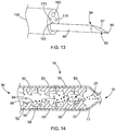
- FIG. 14 an alternative embodiment for containing therapeutic agent 33 and delivering a uniform amount of therapeutic agent 33 is shown.
- the embodiment of FIG. 14 comprises multiple flow obstruction members 50 aligned along an interior surface 17 of a container 16.
- Each flow obstruction member 50 has a preferred annular shape comprising a base 52 secured to the interior surface 17 of the container 16, a peak 54, a convex proximal side 56, and a concave distal side 58, although the proximal side 56 and the distal side 58 may also be concave and convex, respectively.
- the flow obstruction members 50 are depicted as being peak-shaped, but they may comprise any shape suitable for obstructing or halting the flow of some of the therapeutic agent 33 in order to assure that a relatively uniform amount of therapeutic agent 33 is allowed out of the container 16 per blast from the pressure source 70.
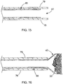
- the catheter 46 is comprised of a shape-memory material and is enclosed within an outer sheath 79. When covered by the sheath 79, the catheter 46 remains in the delivery state as depicted in FIG 15 . When the outer sheath 79 is retracted, a distal end 47 of the catheter 46 expands in a radial direction in the deployed state as depicted in FIG. 16 .
- the distal end 47 of the catheter 46 may comprise nitinol or any other suitable shape-memory material such as those described in U.S.
- the distal end 47 may be coated with a fabric or lubricious polymer such as ethylene tetrafluoroethylene) ("ETFE").
- ETFE ethylene tetrafluoroethylene
- the sheath 79 and the catheter 46 within may pass through the lumen 161 of the endoscope 150.
- the catheter 46 of this embodiment may allow for the therapeutic agent to be delivered in a more precise manner to the target site.
- other items may be passed through the endoscope 150 or lumen 161 simultaneously with the catheter 46.
Landscapes
- Health & Medical Sciences (AREA)
- Life Sciences & Earth Sciences (AREA)
- Heart & Thoracic Surgery (AREA)
- Animal Behavior & Ethology (AREA)
- General Health & Medical Sciences (AREA)
- Veterinary Medicine (AREA)
- Public Health (AREA)
- Engineering & Computer Science (AREA)
- Biomedical Technology (AREA)
- Hematology (AREA)
- Anesthesiology (AREA)
- Pulmonology (AREA)
- Surgery (AREA)
- Vascular Medicine (AREA)
- Pathology (AREA)
- Molecular Biology (AREA)
- Medical Informatics (AREA)
- Radiology & Medical Imaging (AREA)
- Physics & Mathematics (AREA)
- Optics & Photonics (AREA)
- Nuclear Medicine, Radiotherapy & Molecular Imaging (AREA)
- Biophysics (AREA)
- Emergency Medicine (AREA)
- Chemical & Material Sciences (AREA)
- Chemical Kinetics & Catalysis (AREA)
- Infusion, Injection, And Reservoir Apparatuses (AREA)
- Endoscopes (AREA)
Description
- The present embodiments relate generally to medical devices, and more particularly to apparatus for delivering therapeutic agents to a target site.
- There are several instances in which it may become desirable to introduce therapeutic agents into the human or animal body. For example, therapeutic drugs or bioactive materials may be introduced to achieve a biological effect. The biological effect may include an array of targeted results, such as inducing hemostasis, sealing perforations, reducing restenosis likelihood, or treating cancerous tumors or other diseases.
- Many of such therapeutic agents are injected using an intravenous (IV) technique and via oral medicine. While such techniques permit the general introduction of medicine, in many instances it may be desirable to provide localized or targeted delivery of therapeutic agents, which may allow for the guided and precise delivery of agents to selected target sites. For example, localized delivery of therapeutic agents to a tumor may reduce the exposure of the therapeutic agents to normal, healthy tissues, which may reduce potentially harmful side effects.
- Localized delivery of therapeutic agents has been performed using catheters and similar introducer devices. By way of example, a catheter may be advanced towards a target site within the patient, and then the therapeutic agent may be injected through a lumen of the catheter to the target site. Typically, a syringe or similar device may be used to inject the therapeutic agent into the lumen of the catheter. However, such a delivery technique may result in a relatively weak stream of the injected therapeutic agent.
- Moreover, it may be difficult or impossible to deliver therapeutic agents in a targeted manner in certain forms, such as a powder form, to a desired site. For example, if a therapeutic powder is held within a syringe or other container, it may not be easily delivered through a catheter to a target site in a localized manner that may also reduce potentially harmful side effects.
- Reference is directed to
WO2008/008845 , which discloses various multi-reservoir pump devices for different medical applications, including drug delivery, biosensing, and dialysis. The document discloses a pump and reservoir device, which includes a remote pump that is in fluid communication with a reservoir and mixing component through a flexible conduit. The reservoir and mixing component includes a substrate with drug-containing reservoirs arrayed therein. Each reservoir has two openings on opposed sides of the substrate. Reservoirs caps are provided over these openings and can be actively disintegrated to allow pumped carrier fluid to flow into and through the reservoirs and then into a mixing space. The fluidized drug then can flow out of the device through a discharge tube. - It may be noted that, although an end of the discharge tube is connected to the reservoir and mixing component, there is no suggestion that an end of the discharge tube be positioned within the reservoir and mixing component
The document notes generally that, in some of the disclosed constructions, the pump may produce sufficient turbulence to mix drug molecules from the reservoir and the carrier fluid sufficient to form a solution or ordered mixture. It further notes that sufficient turbulence can also be created by incorporating baffles within a flow channel (though it should be noted that it is unclear whether the specific pump and reservoir device discussed above includes such a flow channel) and/or by adding a static or dynamic mixer/agitator. - Reference is further directed to
WO2005/100980 , which discloses disposable sample testing devices. In one disclosed construction, the device is in the form of a single disposable unit that includes a measuring component or volume chamber, reagents located in a mixing chamber or area, and an analysis portion (test chamber). - The document teaches that the sample and reagent are mixed in the mixing chamber. It is disclosed that a mixing pin may be provided in the mixing chamber to assist mixing. The document asserts the two areas around the pin induce a reversed mixing pattern, disrupting the laminar flow completely, resulting in more effective mixing.
- Reference is still further directed to
US2007/240989 , which discloses microfluidic pumps and mixers driven by induced-charge electro-osmosis. - It may be noted that, in one disclosed construction, a tear-drop asymmetric shaped conductor is used to produce a directed induced-charge electro-osmotic flow under the influence of an AC electric field.
- It is proposed that the general teaching of the document may be applied to drug delivery devices which convey fluid from a reservoir to an outlet port. In one example, it is suggested that mixing of drug concentrations may take place in the device.
- The present embodiments provide apparatus suitable for containing a therapeutic agent and delivering it to a target side as stated in the
independent claim 1 and its dependent claims. The apparatus generally comprises at least one container for holding a therapeutic agent, and a pressure source for facilitating delivery of the therapeutic agent. - In one embodiment, the pressure source may be placed in selective fluid communication with a proximal end of the container. Fluid from the pressure source may flow through at least a portion of the container to urge the therapeutic agent through a distal end of the container and towards the target site. The pressure source may comprise a compressed gas dispenser.
- At least one tube member, such as a catheter, may be used to facilitate delivery of the therapeutic agent from the container to the target site. The catheter may be placed in fluid communication with the distal region of the container. In use, fluid from the pressure source urges the therapeutic agent through the container, through the catheter, and then distally towards the target site.
- The container has a proximal end and a distal end that may be closed by pregnable sealing members. The container is designed to control the flow of therapeutic agent through the tube member in order to provide a consistent, uniform amount with each use. In one embodiment, the container comprises a tube member held preferably at about the radial center of the container near the distal end. A plug holds the tube member in place and has an outer diameter that is approximately equal to the interior of the container, so that it prevents any therapeutic agent that does not pass through the tube member from exiting the distal end of the container.
- In one embodiment, a flow obstruction member is placed preferably at about the radial center of the container and proximally adjacent to the tube member. A support member, comprised of a wire or other suitable material, is coupled to the flow obstruction member and is held in place by a support structure. The support structure and support member, in combination, maintain the flow obstruction member in place. When fluid from the pressure source enters the container, it forces therapeutic agent to travel around the flow obstruction member so that a certain amount of therapeutic agent is directed through the tube member to be delivered to the target site.
- In another embodiment, the container does not contain a tube member, but instead comprises flow obstruction members placed along the interior of the container that are designed to promote the delivery of a consistent, uniform amount of therapeutic agent with each use.
- In any of the embodiments, switches may be placed at the proximal and distal ends of the container in order to control when fluid from the pressure source may enter the container and push the therapeutic agent into the catheter. If pregnable seals are used, the switches may also be used to perforate the seals surrounding the container. Additionally, a valve may be placed in fluid communication between the pressure source and the container so that the fluid from the pressure source bypasses the container entirely and then enters the catheter in order to clear the catheter of any excess therapeutic agent.
- Other features and advantages of the invention will be, or will become, apparent to one with skill in the art upon examination of the following figures and detailed description. It is intended that all such additional features and advantages be within the scope of the invention, and be encompassed by the following claims.
- The invention can be better understood with reference to the following drawings and description. The components in the figures are not necessarily to scale, emphasis instead being placed upon illustrating the principles of the invention. Moreover, in the figures, like referenced numerals designate corresponding parts throughout the different views.
-
FIG. 1 is a side sectional view of an apparatus for containing and delivering therapeutic agent to a target site in a patient. -
FIG. 2 is a schematic view of a first embodiment of a container. -
FIG. 3 is a side sectional view illustrating the first embodiment ofFIG. 2 with a therapeutic agent present inside the container. -
FIG. 4 is an end view of a flow obstruction member, and a support structure and support member of the embodiment ofFIG. 2 . -
FIG. 5 is a side view of the tube member and the plug of the embodiment ofFIG. 2 . -
FIG. 6 is a side sectional view of the embodiment ofFIG. 2 with switches depicted in a closed state. -
FIG. 7 is a side sectional view of the embodiment ofFIG. 2 with switches depicted in an open state. -
FIG. 8 is a schematic view of a therapeutic agent being forced past a flow obstruction member and into a tube member. -
FIG. 9 is a schematic view of therapeutic agent being forced past an alternative flow obstruction member and into the tube member. -
FIG. 10 is a flow chart view depicting components of an exemplary system for containing and delivering a therapeutic agent to a target site in a patient. -
FIG. 11 is a schematic view of an apparatus for containing and delivering a therapeutic agent to a target site in a patient in accordance with one embodiment. -
FIG. 12 is a schematic view of an apparatus for clearing a therapeutic agent out of a catheter. -
FIG. 13 is a perspective view of a distal end of an exemplary end-viewing endoscope and a needle that may be used in conjunction with the apparatus ofFIG. 1 . -
FIG. 14 is a side sectional view of an alternative embodiment of a container. -
FIG. 15 is a side sectional view of one embodiment of a catheter in a delivery state. -
FIG. 16 is a side sectional view of one embodiment of a catheter in a deployed state. - In the present application, the term "proximal" refers to a direction that is generally towards a physician during a medical procedure, while the term "distal" refers to a direction that is generally towards a target site within a patient's anatomy during a medical procedure.
- Referring now to
FIG. 1 , a first embodiment of an apparatus suitable for containing and delivering a therapeutic agent to a target site within a patient is shown. The apparatus comprises apressure source 70 and acontainer 18 and acatheter 46. For example, as shown inFIG. 1 , thepressure source 70 comprises apressurized fluid cartridge 72, and ahousing 71 that at least partially encapsulates or covers thepressurized fluid cartridge 72. - The
pressure source 70 may comprise one or more components capable of producing or furnishing a fluid having a desired pressure. In one embodiment, thepressure source 70 may comprise apressurized fluid cartridge 72 comprised of a selected gas or liquid - or a combination of gas and liquid - such as carbon dioxide, nitrogen, or any other suitable gas or liquid that may be compatible with the human body. Thepressurized fluid cartridge 72 may contain the gas or liquid at a relatively high, first predetermined pressure, for example, around 12 MPa (1,800 psi) inside of the cartridge. The fluid may flow from thepressurized fluid cartridge 72 through a pressure regulator, such asregulator valve 73 having a pressure outlet, which may reduce the pressure to a lower, second predetermined pressure or to achieve a set flow rate. Solely by way of example, the second predetermined pressure may be in the range of about 0.21 MPa (30 psi) to about 0.55MPa (80 psi), although any suitable pressure may be provided for the purposes described below. Therapeutic agent is disposed within thecontainer 18. Thepressure source 70 propels fluid from thepressurized fluid cartridge 72 distally through thecontainer 18 and through thecatheter 46. In other embodiments, thepressure source 70 may comprise a compressible ball or a syringe. An inner diameter dl of thecatheter 46 may vary, but a preferred inner diameter ranges from about 2.16mm (.085 inches) to about 2.54mm (.100 inches). - Referring now to
FIGS. 1-5 , further features of thecontainer 18 are described in greater detail. In this embodiment, the apparatus comprises acontainer 18 that that has anouter surface area 21 that is generally cylindrical, and has a preferred outer diameter ranging from about 23mm (.90 inches) to about 28mm (1.10 inches). Thecontainer 18 further comprises aninterior surface 19 and athickness 23, wherein a preferred thickness is about 2.5mm (.10 inches) to about 7.6mm (.30 inches). Thecontainer 18 is configured to hold atherapeutic agent 33. Thecontainer 18 further comprises asupport structure 24 that is preferably near aproximal end 32 of thecontainer 18, but that could be disposed at almost any position in thecontainer 18. Thesupport structure 24 is connected to aflow obstruction member 26 via asupport member 28. Theflow obstruction member 26 is preferably positioned at about the radial center of thecontainer 18. Thesupport structure 24 preferably projects inwardly towards the radial center of thecontainer 18. In this embodiment, theflow obstruction member 26 is generally spherical and thesupport structure 24 is generally cylindrical, preferably thesupport structure 24 is a ring or short-cylinder sized to fit inside theinterior surface 19 ofcontainer 18. A diameter of theflow obstruction member 26 may vary, but a preferred range is about 6.4mm (.25 inches) to about 8.9mm (.35 inches). Thesupport member 28 may comprise a wire, rod, or other suitable materials for holding theflow obstruction member 26 in place. Thesupport structure 24, flowobstruction member 26, andsupport member 28 also may be composed of one solid piece. - The
container 18 further comprises atube member 22 that has adistal end 37 that is located near adistal end 30 of thecontainer 18. A diameter of thetube member 22 may vary, but a preferred range in outer diameter is about 5.8mm (.23 inches) to about 6.9mm (.27 inches) and a preferred inner diameter d2 ranges from about 4.8mm (.19 inches) to about 5.6mm (.22 inches). Thetube member 22 extends to a position proximate to theflow obstruction member 26. While a distance rl from thetube member 22 to theflow obstruction member 26 may vary, a preferred range of distance rl is about .25 mm to about .35 mm. Thedistal end 37 of thetube member 22 may extend distally up to or beyond the distal end of thecontainer 18. Thetube member 22 preferably does not directly abut or touch theflow obstruction member 26, and is held preferably at about the radial center of thecontainer 18 by aplug 20. In this embodiment, theplug 20 is disc-shaped. An outer diameter of theplug 20 is equal to or slightly less than a diameter of aninterior surface 19 of thecontainer 18 so as to form a seal between theplug 20 and theinterior surface 19 to prevent any therapeutic agent from reaching thedistal end 30 of thecontainer 18 without passing through thetube member 22. Thecontainer 18 may also be sealed by sealingmembers 25, with one at thedistal end 30 as depicted inFIG. 2 and another sealingmember 25 located at the proximal end 32 (not shown). In alternative embodiments where thedistal end 37 of thetube member 22 extends distally past thedistal end 30 of thecontainer 18, the sealingmember 25 would encapsulate thedistal end 37 of thetube member 22. - The
container 18 may comprise any suitable size and shape for holding atherapeutic agent 33. In alternative embodiments wherein the container is not cylindrical in shape, thesupport structure 24 and theplug 20 will be made out of shapes necessary to prevent therapeutic agent from reaching thedistal end 30 through routes other than through thetube member 22. - The
flow obstruction member 26 may comprise any suitable shape for controlling the rate of flow of the therapeutic agent into thetube member 22. When fluid from thepressure source 70 enters thecontainer 18 through aninlet port 35, the fluid travels around theflow obstruction member 26 and tends to travel along the surface of theflow obstruction member 26. As the fluid continues past thetube member 22, the fluid creates a pressure differential wherein the resulting lower pressure within thetube member 22 drawstherapeutic agent 33 into thetube member 22. Without theflow obstruction member 26, thetherapeutic agent 33 would flow in a haphazard, turbulent manner toward the distal end of thecontainer 18, and a non-uniform amount oftherapeutic agent 33 would pass through thetube member 22. As depicted inFIGS. 8 and 9 , the flow obstruction members produce a more laminar flow oftherapeutic agent 33, and therefore, a uniform amount oftherapeutic agent 33 passes through thetube member 22. Arrows labeled 1 indicate the flow of the fluid around theflow obstruction member 26, and arrows labeled 2 represent thetherapeutic agent 33 being drawn into thetube member 22. The more laminar flow caused by theflow obstruction member 26 may result in a generally uniform dispersion of thetherapeutic agent 33 and the fluid within thetube member 22. A preferred ratio of fluid totherapeutic agent 33 may range from about 1:5 to about 1:1, but is most preferably about 1:1. The more laminar flow caused by theflow obstruction member 26 may also result in a consistent volumetric flow rate, which is a range of about +/- 10% of a predetermined flow rate. The uniformity and consistency of the mixture and its flow may vary depending on the fluid and agent used (e.g., based on particle size, density, viscosity, etc.) as will readily be appreciated by those skilled in the art. - Depicted in
FIGS. 8 and 9 are a sphere-shapedflow obstruction member 26 and a tear drop-shaped flow obstruction member 26', respectively. Referring toFIG. 9 , the tip of the "tear" extends longitudinally toward thetube member 22. In another embodiment, theflow obstruction member 26 may comprise a dimpled sphere shape, similar to a golf ball. The tear drop-shaped flow obstruction member 26' ofFIG. 9 may result in a more laminar flow than the sphere-shapedflow obstruction member 26 ofFIG. 8 and is preferred. - The
container 18 also may comprise measurement indicia, which allow a user to determine a quantity of thetherapeutic agent 33 that is held within thecontainer 18, as explained in commonly assigned pendingU.S. Application Number 12/435,574 container 18 and thecatheter 46 to selectively permit and inhibit fluid communication between thecontainer 18 and thecatheter 46, as further described in the '574 application. - Referring now to
FIGS. 1 and10-12 , an actuator, such as a button, may be used to selectively actuate thepressure source 70. The pressurized fluid may flow from thepressurized fluid cartridge 72, and subsequently through theregulator valve 73 using an adapter, as explained in the '574 application. The adapter may be configured to be sealingly coupled to thepressurized fluid cartridge 72, as further explained in the'574 application. Further, the adapter may be coupled to tubing, which allows the pressurized fluid to flow into the regulator valve. A proximal end of a different tubing may be adapted to be coupled to theregulator valve 73, as shown in the '574 application, thereby enabling the pressurized fluid to flow through theregulator valve 73 and into the tubing at the lower, second predetermined pressure. - The
pressure source 70 optionally may comprise one or more commercially available components. Solely by way of example, thepressurized fluid cartridge 72 may comprise a disposable carbon dioxide cartridge, such as the Visage® commercial dispenser manufactured by Helen of Troy®, El Paso, Texas. Thepressure source 70 therefore may comprise original or retrofitted components capable of providing a fluid or gas into the tubing at a desired regulated pressure. - One or more catheters may be used to deliver the
therapeutic agent 33 to a target site. Referring toFIGS. 1 ,11, and 12 , thecatheter 46 comprises a proximal end that may be placed in fluid communication with thedistal end 30 of thecontainer 18 using a suitable coupling mechanism or arrangement. Thecatheter 46 further comprises a distal end that may facilitate delivery of thetherapeutic agent 33 to a target site, as set forth below. Thecatheter 46 may comprise a flexible, tubular member that may be formed from one or more semi-rigid polymers. For example, the catheter may be manufactured from polyurethane, polyethylene, tetrafluoroethylene, polytetrafluoroethylene, fluorinated ethylene propylene, nylon, PEBAX or the like. - Referring to
FIG. 13 , the apparatus for delivering the therapeutic agent may further comprise anendoscope 150 and aneedle 95 suitable for penetrating tissue, or just a needle without the endoscope (not shown). Theneedle 95 may be coupled to adistal end 94 of thecatheter 46 to form a sharp, distal region configured to pierce through a portion of a patient's tissue, or through a lumen wall to perform a translumenal procedure. InFIG. 13 , theneedle 95 may be formed as an integral component with thecatheter 46, i.e., such that distal movement of thecatheter 46 causes distal advancement of theneedle 95. In this embodiment, a relatively sharp needle tip may be affixed to the distal tip of the catheter 90, e.g., using an adhesive, to form a needle-shaped element at the distal end of the catheter. Alternatively, a separate needle configured to be inserted through a lumen of the catheter 90 may be employed. - In addition, end-viewing and side-viewing endoscopes may be used, as described in the '574 application. The endoscopes may be advanced through a bodily lumen such as the alimentary canal to a position proximate the target location. The
catheter 46 then may be advanced through the working lumen of the endoscope. If theneedle 95 is employed, a sharpenedtip 96 of theneedle 95 may extend distal to the endoscope, and may be used to puncture through an organ or a gastrointestinal wall or tissue. At this time, thetherapeutic agent 33 may be delivered through thecatheter 46, then through abore 97 in theneedle 95, in the manner described above and in the '574 application. - In operation, the apparatus of
FIGS. 1 and10-13 may be used to deliver thetherapeutic agent 33 to a target site within a patient's body. In a first step, the distal end of thecatheter 46 may be positioned in relatively close proximity to the target site. Thecatheter 46 may be advanced to the target site using an open technique, a laparoscopic technique, an intraluminal technique, using a gastroenterology technique through the mouth, colon, or using any other suitable technique. - The
catheter 46 may comprise one or more markers (not shown), which may be disposed near the distal end of thecatheter 46. The markers may be configured to be visualized under fluoroscopy or other imaging techniques to facilitate location of the distal end of thecatheter 46. If theneedle 95 is integral to thecatheter 46, theneedle 95 also may be visualized using the imaging techniques, thereby allowing placement of the distal end of thecatheter 46 in close proximity to the target site. If desired, thecatheter 46 may be advanced through a working lumen of an endoscope, as explained in further detail in the '574 application. - When the
catheter 46 is positioned at the desired location, thepressure source 70 may be actuated. As noted above, a button or other actuator may be coupled to thepressurized fluid cartridge 72 to release a relatively high pressure fluid. As noted above, the pressurized fluid may flow through aregulator valve 73 and through thecontainer 18 at a desired pressure and rate. For example, the regulator valve may automatically set the pressure for fluid flow, or alternatively, a control mechanism coupled to the pressurized fluid cartridge and/or the regulator valve may be activated by a user to set the desired pressure for fluid flow into thecontainer 18. Such a control mechanism also may be used to variably permit fluid flow into thecontainer 18, e.g., fluid from thepressurized fluid cartridge 72 may flow into thecontainer 18 at a desired time interval, for example, a predetermined quantity of fluid per second. Moreover, the control mechanism may be pre-programmed to deliver a predetermined amount of the therapeutic agent, depending on the type, viscosity, and other properties of the agent. Empirical information, such as a table of pressure, time and delivered quantity, may be stored and used for the different agents or procedures. - Fluid from the
pressure source 70 flows through theproximal end 32 of thecontainer 18, around theobstruction flow member 26 and into thetube member 22, through thedistal end 30 and then through a lumen of thecatheter 46. Fluid may exit the distal end of thecatheter 46, for example, through a bore formed in theneedle 95. In addition, the orientation ofcontainer 18 in regards to thepressure source 70 may vary. For example, thecontainer 18 may be aligned parallel to thepressure source 70 as described inU.S. Application Number 61/182,463 filed May 29, 2009 - As noted above, a valve member optionally may be disposed between the reservoir of the
container 18 and a connecting member, as shown in the '574 application. A user may selectively actuate the valve member to periodically permit and inhibit fluid communication between the container and the connecting member. The valve member also may serve as a "shut-off' safety mechanism to inhibit withdrawal of the therapeutic agent from the reservoir, even when pressurized fluid is flowing through the connecting member. - As noted above and depicted in the '574 application, a control mechanism coupled to the
pressure source 70 may variably permit fluid flow into the tubing from thepressurized fluid cartridge 72 at a desired time interval, for example, a predetermined quantity of fluid per second. In this manner, pressurized fluid may flow through the catheter periodically, and thetherapeutic agent 33 may be delivered to a target site at a predetermined interval or otherwise periodic basis. - The apparatus may be used to deliver the
therapeutic agent 33 in a wide range of procedures and thetherapeutic agent 33 may be chosen to perform a desired function upon ejection from the distal end of thecatheter 46. Solely by way of example, and without limitation, the provision of thetherapeutic agent 33 may be used for providing hemostasis; closing perforations; performing lithotripsy; delivering drugs; treating tumors and cancers; and treating renal dialysis fistulae stenosis, vascular graft stenosis, and the like. The size of thecatheter 46 used to deliver thetherapeutic agent 33 may vary depending upon the procedure for which it is being used; for example, a short catheter may be used for external use on irregularly shaped lacerations. The size of thetherapeutic agent 33 may also vary, although a preferred embodiment of atherapeutic agent 33 for hemostasis has a 325 mesh size. - The
therapeutic agent 33 can be delivered during procedures such as coronary artery angioplasty, renal artery angioplasty and carotid artery surgery, or may be used generally for treating various other cardiovascular, respiratory, gastroenterology or other conditions. The above-mentioned systems also may be used in transvaginal, umbilical, nasal, and bronchial/lung related applications. - For example, if used for purposes of hemostasis, thrombin, epinephrine, or a sclerosant may be provided to reduce localized bleeding. Similarly, if used for closing a perforation, a fibrin sealant may be delivered to a localized lesion. In addition to the hemostatic properties of the
therapeutic agent 33, it should be noted that the relatively high pressure of the fluid and therapeutic agent, by itself, may act as a mechanical tamponade by providing a compressive force, thereby reducing the time needed to achieve hemostasis. - The
therapeutic agent 33 may be selected to perform one or more desired biological functions, for example, promoting the ingrowth of tissue from the interior wall of a body vessel, or alternatively, to mitigate or prevent undesired conditions in the vessel wall, such as restenosis. Many other types oftherapeutic agents 33 may be used in conjunction with the apparatus. - The
therapeutic agent 33 may be delivered in any suitable form. For example, thetherapeutic agent 33 may comprise a powder, liquid, gel, aerosol, or other substance. Advantageously, thepressure source 70 may facilitate delivery of thetherapeutic agent 33 in any one of these forms. - The
therapeutic agent 33 employed also may comprise an antithrombogenic bioactive agent, e.g., any bioactive agent that inhibits or prevents thrombus formation within a body vessel. Types of antithrombotic bioactive agents include anticoagulants, antiplatelets, and fibrinolytics. Anticoagulants are bioactive materials which act on any of the factors, cofactors, activated factors, or activated cofactors in the biochemical cascade and inhibit the synthesis of fibrin. Antiplatelet bioactive agents inhibit the adhesion, activation, and aggregation of platelets, which are key components of thrombi and play an important role in thrombosis. Fibrinolytic bioactive agents enhance the fibrinolytic cascade or otherwise aid in dissolution of a thrombus. Examples of antithrombotics include but are not limited to anticoagulants such as thrombin, Factor Xa, Factor VIIa and tissue factor inhibitors; antiplatelets such as glycoprotein IIb/IIIa, thromboxane A2, ADP-induced glycoprotein IIb/IIIa, and phosphodiesterase inhibitors; and fibrinolytics such as plasminogen activators, thrombin activatable fibrinolysis inhibitor (TAFI) inhibitors, and other enzymes which cleave fibrin. - Additionally, or alternatively, the
therapeutic agent 33 may include thrombolytic agents used to dissolve blood clots that may adversely affect blood flow in body vessels. A thrombolytic agent is any therapeutic agent that either digests fibrin fibers directly or activates the natural mechanisms for doing so. Examples of commercial thrombolytics, with the corresponding active agent in parenthesis, include, but are not limited to, Abbokinase (urokinase), Abbokinase Open-Cath (urokinase), Activase (alteplase, recombinant), Eminase (anitstreplase), Retavase (reteplase, recombinant), and Streptase (streptokinase). Other commonly used names are anisoylated plasminogen-streptokinase activator complex; APSAC; tissue-type plasminogen activator (recombinant); t-PA; rt-PA. While a few exemplarytherapeutic agents 33 have been listed, it will be apparent that numerous other suitable therapeutic agents may be used in conjunction with the apparatus and delivered through thecatheter 46. - Advantageously, the apparatus permits localized delivery of a desired quantity of the
therapeutic agent 33 at a desired pressure via thepressure source 70. Since the distal end of thecatheter 46 may be placed in relatively close proximity to a target site, the apparatus provides significant advantages over therapeutic agents delivered orally or through an IV system and may reduce accumulation of thetherapeutic agent 33 in healthy tissues, thereby reducing side effects. Moreover, the delivery of thetherapeutic agent 33 to the target site is performed in a relatively fast manner due to the relatively high pressure of the fluid, thereby providing a prompt delivery to the target site compared to previous devices. - Further, if the
optional needle 95 is employed, the apparatus advantageously may be used both to perforate tissue at or near a target site, and then deliver thetherapeutic agent 33 at a desired pressure in the manner described above. For example, theneedle 95 may comprise an endoscopic ultrasound (EUS) needle. Accordingly, in one exemplary technique, a sharpened tip of theneedle 95 may be capable of puncturing through an organ or a gastrointestinal wall or tissue, so that thetherapeutic agent 33 may be delivered at a predetermined pressure in various bodily locations that may be otherwise difficult to access. One or more delivery vehicles, such as an endoscope or sheath, may be employed to deliver thecatheter 46 to a target site, particularly if the distal end of thecatheter 46 comprises theoptional needle 95. - Referring now to
FIGS. 6 and 7 , in this embodiment, aswitch 40 may be used to selectively open and close theproximal end 32 of thecontainer 18, and aswitch 42 may be used to selectively open and close thedistal end 37 of thetube member 22. Each of theswitches opening 44 therein. When theswitches FIG. 7 , fluid from thepressure source 70 will enter theproximal end 32 of thecontainer 18 and will propel at least sometherapeutic agent 33 within thecontainer 18 through thetube member 46 to be delivered to a target site. In the closed position depicted inFIG. 6 , no fluid from thepressure source 70 will be able to enter thecontainer 18, and therefore no therapeutic agent will be delivered to the target site. - In the embodiment depicted in
FIGS. 6 and 7 , theswitches members 25. When theswitches members 25, they perforate the sealingmembers 25 when depressed into the open position for the first time, thereby allowing at least sometherapeutic agent 33 to travel through thedistal end 37 of thetube member 22 and into thecatheter 46 to be delivered to a target site. When returned to the closed position depicted inFIG. 6 , theswitches catheter 46 even after the sealingmembers 25 have been perforated. In an alternative embodiment, stopcocks or valves that are typically used with catheters could substitute for theswitches distal end 37 of thetube member 22 is the male end of a threaded luer. - Referring again to
FIGS. 11 and 12 , aclearing valve 60 may be used. In the "on" position, apiston 61 having anopening 64 formed therein is located in thevalve 60 so that theopening 64 is in fluid communication with a proximal end of a firsthollow tube 62, such as a catheter. A distal end of thehollow tube 62 is in fluid communication with a container holdingtherapeutic agent 33. In this embodiment, fluid from thepressure source 70 travels through thevalve 60 and thehollow tube 62 and into thecontainer 18, where it can propeltherapeutic agent 33 through thedistal end 30 of thecontainer 18 and deliver thetherapeutic agent 33 through thecatheter 46 to a target site within a patient. In the "off" position depicted inFIG. 12 , thepiston 61 is located so that theopening 64 is aligned with a secondhollow tube 63 that is not in fluid communication with thecontainer 18. In this embodiment, fluid from thepressure source 70 passes through thecatheter 46 and forces anytherapeutic agent 33 that may have accumulated in thecatheter 46 to exit thecatheter 46. Acheck valve 65, or a one-way valve-located at a position distal to the container and proximal to the catheter 46-prevents anytherapeutic agent 33 from traveling into thecatheter 46. This ensures that when thevalve 60 is in the "on" position, a uniform amount oftherapeutic agent 33 is delivered to a target site within a patient. - Referring now to
FIG. 14 , an alternative embodiment for containingtherapeutic agent 33 and delivering a uniform amount oftherapeutic agent 33 is shown. Instead of one flow obstruction member and a tube member of the embodiment shown inFIG. 1 , the embodiment ofFIG. 14 comprises multipleflow obstruction members 50 aligned along aninterior surface 17 of acontainer 16. Each flowobstruction member 50 has a preferred annular shape comprising a base 52 secured to theinterior surface 17 of thecontainer 16, apeak 54, a convexproximal side 56, and a concavedistal side 58, although theproximal side 56 and thedistal side 58 may also be concave and convex, respectively. - In the embodiment of
FIG. 14 , when the fluid from a single blast of thepressure source 70 enters thecontainer 16 through theproximal end 36, a relatively uniform amount of thetherapeutic agent 33 contained within thecontainer 16 is propelled longitudinally through thecontainer 16 and out through thedistal end 34. The relatively uniform amount is obtained, because sometherapeutic agent 33 becomes obstructed by and accumulates behind and around theflow obstruction members 50 after the fluid from the pressure source enters and moves toward thedistal end 34 of thecontainer 16. During each blast, a certain amount oftherapeutic agent 33 that has accumulated behind each flowobstruction member 50 is picked up by the longitudinally advancing fluid and is circulated towards thedistal end 34 of thecontainer 16. InFIG. 14 , theflow obstruction members 50 are depicted as being peak-shaped, but they may comprise any shape suitable for obstructing or halting the flow of some of thetherapeutic agent 33 in order to assure that a relatively uniform amount oftherapeutic agent 33 is allowed out of thecontainer 16 per blast from thepressure source 70. - Referring now to
FIGS. 15 and 16 , an alternative embodiment of thecatheter 46 is shown, which may be substituted for any embodiments of thecatheter 46 previously described herein. In this embodiment, thecatheter 46 is comprised of a shape-memory material and is enclosed within anouter sheath 79. When covered by thesheath 79, thecatheter 46 remains in the delivery state as depicted inFIG 15 . When theouter sheath 79 is retracted, adistal end 47 of thecatheter 46 expands in a radial direction in the deployed state as depicted inFIG. 16 . Thedistal end 47 of thecatheter 46 may comprise nitinol or any other suitable shape-memory material such as those described inU.S. Application Number 12/428,226 filed April 22, 2009 distal end 47 may be coated with a fabric or lubricious polymer such as ethylene tetrafluoroethylene) ("ETFE"). When used in conjunction with anendoscope 150, thesheath 79 and thecatheter 46 within may pass through thelumen 161 of theendoscope 150. Thecatheter 46 of this embodiment may allow for the therapeutic agent to be delivered in a more precise manner to the target site. By using thesheath 79 to maintain thecatheter 46 and thedistal end 47 in the delivery state, other items may be passed through theendoscope 150 orlumen 161 simultaneously with thecatheter 46. - While various embodiments of the invention have been described, the invention is not to be restricted except in light of the attached claims and their equivalents. Moreover, the advantages described herein are not necessarily the only advantages of the invention and it is not necessarily expected that every embodiment of the invention will achieve all of the advantages described.
Claims (12)
- Apparatus suitable for facilitating delivery of a therapeutic agent, the apparatus comprising:a pressure source (70);a container (18) having proximal (32) and distal (30) ends with an inlet port (35) at the proximal end for receiving a fluid from the pressure source (70);a therapeutic agent (33) disposed within the container (18); anda tube member (22) having proximal and distal (37) ends,characterized in that:the proximal end of the tube member is positioned within the container (18); andthe apparatus further comprises a flow obstruction member (26) positioned within the container (18) between the inlet port (35) and the proximal end of the tube member (22), the flow obstruction member structured to direct fluid around the flow obstruction member (26) and towards the proximal end of the tube member (22), the flow obstruction member (26) and the tube member (22) being spaced relative to each other to cause the fluid to flow around the obstruction member (26) and draw the therapeutic agent (33) into the tube member (22) and direct the therapeutic agent distally therethrough.
- The apparatus of claim 1 further comprising at least one sealing member (25) located at the proximal end of the container (32) and at least one sealing member (25) located at the distal end of the container.
- The apparatus of claim 1 further comprising:a switch (40) located at the proximal end (32) of the container (18) and a switch (42) located at the distal end (30) of the container (18);an opening (44) located in the interior of each switch;the switches (40, 42) having a first position wherein the openings (44) are not in fluid communication with the proximal (32) and distal (30) ends of the container (18); andthe switches (40, 42) having a second position wherein the switches are in fluid communication the proximal (32) and distal (30) ends of the container (18).
- The apparatus of claim 1 wherein the flow obstruction member (26) comprises a sphere shape.
- The apparatus of claim 1 wherein the flow obstruction member (26) comprises a tear drop shape oriented with a rounded end facing the inlet port (35).
- The apparatus of claim 1 further comprising a support structure (24) connected to the container (18) and having a support member (28) projecting radially inwardly, the support structure (24) being connected to the flow obstruction member (26) via said support member (28), preferably wherein a plug (20) maintains the tube member (22) in about the radial center of the container (18).
- The apparatus of claim 1 wherein the flow obstruction member (26) is sized according to the container (18) in order to create a pressure differential whereby the resulting lower pressure within the tube member draws therapeutic agent (33) into the tube member.
- The apparatus of claim 1 wherein the flow obstruction member (26) is configured so as in use to result in a laminar flow of the therapeutic agent (33).
- The apparatus of claim 1 wherein the container (18) has an outer diameter ranging from about 23mm to about 28mm, the flow obstruction member (26) has a diameter ranging from about 6.4mm to about 8.9mm, the tube member (22) has an inner diameter ranging from about 4.8mm to about 5.6mm, and a distance between the flow obstruction member (26) and the tube member (22) ranging from about .25 mm to about .35 mm.
- The apparatus of claim 1 so configured that in use the fluid and the therapeutic agent (33) are mixed together within the tube member to form a mixture, the mixture having a generally uniform dispersion of the therapeutic agent (33) within the fluid.
- The apparatus of claim 1 further comprising:a first hollow tube (62) having proximal and distal ends, wherein the distal end of the first hollow tube is in fluid communication with the proximal end of the container;a second hollow tube (63) having proximal and distal ends, wherein the distal end of the second hollow tube is in fluid communication with the proximal end of a catheter (46); andthe apparatus operable in at least two states including,a first state wherein the pressure source (70) is in fluid communication with the proximal end of the first hollow tube (62) and the container (18), wherein the provision of a fluid from the pressure source (70) through at least a portion of the container (18) is adapted to urge the therapeutic agent (33) towards the distal end of the container and through the catheter (46) in a distal direction towards a target site;a second state wherein the pressure source (70) is in fluid communication with the proximal end of the second hollow tube (63) and communicates with the proximal end of the catheter (46), wherein the provision of a fluid from the pressure source (70) bypasses the container (18) and flows through the catheter (46).
- The apparatus of claim 11 further comprising:a valve (60) placed between the pressure source (70) and the first (62) and second (63) hollow tubes;the valve (60) maintaining fluid communication between the pressure source (70) andthe first (62) and second (63) hollow tubes; andthe valve (60) comprising a piston (61) with an opening (64) located in the interior of the piston that controls whether the pressure source is in fluid communication with the first hollow tube (62) or the second hollow tube (63).
Applications Claiming Priority (2)
| Application Number | Priority Date | Filing Date | Title |
|---|---|---|---|
| US14037908P | 2008-12-23 | 2008-12-23 | |
| PCT/US2009/067076 WO2010074949A1 (en) | 2008-12-23 | 2009-12-08 | Apparatus and methods for containing and delivering therapeutic agents |
Publications (2)
| Publication Number | Publication Date |
|---|---|
| EP2375960A1 EP2375960A1 (en) | 2011-10-19 |
| EP2375960B1 true EP2375960B1 (en) | 2018-10-31 |
Family
ID=41647257
Family Applications (1)
| Application Number | Title | Priority Date | Filing Date |
|---|---|---|---|
| EP09768301.5A Active EP2375960B1 (en) | 2008-12-23 | 2009-12-08 | Apparatus for containing and delivering therapeutic agents |
Country Status (6)
| Country | Link |
|---|---|
| US (1) | US8361054B2 (en) |
| EP (1) | EP2375960B1 (en) |
| JP (1) | JP5631332B2 (en) |
| AU (1) | AU2009330505A1 (en) |
| CA (1) | CA2747390C (en) |
| WO (1) | WO2010074949A1 (en) |
Cited By (1)
| Publication number | Priority date | Publication date | Assignee | Title |
|---|---|---|---|---|
| WO2023076076A1 (en) * | 2021-10-25 | 2023-05-04 | Cook Medical Technologies Llc | Systems for delivering pressurized fluid to a target site alone or in conjunction with therapeutic agents |
Families Citing this family (66)
| Publication number | Priority date | Publication date | Assignee | Title |
|---|---|---|---|---|
| US7909851B2 (en) | 2006-02-03 | 2011-03-22 | Biomet Sports Medicine, Llc | Soft tissue repair device and associated methods |
| US8137382B2 (en) | 2004-11-05 | 2012-03-20 | Biomet Sports Medicine, Llc | Method and apparatus for coupling anatomical features |
| US8298262B2 (en) | 2006-02-03 | 2012-10-30 | Biomet Sports Medicine, Llc | Method for tissue fixation |
| US7905904B2 (en) | 2006-02-03 | 2011-03-15 | Biomet Sports Medicine, Llc | Soft tissue repair device and associated methods |
| US7749250B2 (en) | 2006-02-03 | 2010-07-06 | Biomet Sports Medicine, Llc | Soft tissue repair assembly and associated method |
| US8303604B2 (en) | 2004-11-05 | 2012-11-06 | Biomet Sports Medicine, Llc | Soft tissue repair device and method |
| US8128658B2 (en) | 2004-11-05 | 2012-03-06 | Biomet Sports Medicine, Llc | Method and apparatus for coupling soft tissue to bone |
| US8361113B2 (en) | 2006-02-03 | 2013-01-29 | Biomet Sports Medicine, Llc | Method and apparatus for coupling soft tissue to a bone |
| US8088130B2 (en) | 2006-02-03 | 2012-01-03 | Biomet Sports Medicine, Llc | Method and apparatus for coupling soft tissue to a bone |
| US9801708B2 (en) | 2004-11-05 | 2017-10-31 | Biomet Sports Medicine, Llc | Method and apparatus for coupling soft tissue to a bone |
| US8118836B2 (en) | 2004-11-05 | 2012-02-21 | Biomet Sports Medicine, Llc | Method and apparatus for coupling soft tissue to a bone |
| US9017381B2 (en) | 2007-04-10 | 2015-04-28 | Biomet Sports Medicine, Llc | Adjustable knotless loops |
| US7658751B2 (en) | 2006-09-29 | 2010-02-09 | Biomet Sports Medicine, Llc | Method for implanting soft tissue |
| US7833189B2 (en) | 2005-02-11 | 2010-11-16 | Massachusetts Institute Of Technology | Controlled needle-free transport |
| CA2597940A1 (en) | 2005-02-15 | 2006-08-24 | Virginia Commonwealth University | Mineral technologies (mt) for acute hemostasis and for the treatment of acute wounds and chronic ulcers |
| US8562645B2 (en) | 2006-09-29 | 2013-10-22 | Biomet Sports Medicine, Llc | Method and apparatus for forming a self-locking adjustable loop |
| US10517587B2 (en) | 2006-02-03 | 2019-12-31 | Biomet Sports Medicine, Llc | Method and apparatus for forming a self-locking adjustable loop |
| US9149267B2 (en) | 2006-02-03 | 2015-10-06 | Biomet Sports Medicine, Llc | Method and apparatus for coupling soft tissue to a bone |
| US9468433B2 (en) | 2006-02-03 | 2016-10-18 | Biomet Sports Medicine, Llc | Method and apparatus for forming a self-locking adjustable loop |
| US8801783B2 (en) | 2006-09-29 | 2014-08-12 | Biomet Sports Medicine, Llc | Prosthetic ligament system for knee joint |
| US8597327B2 (en) | 2006-02-03 | 2013-12-03 | Biomet Manufacturing, Llc | Method and apparatus for sternal closure |
| US8652171B2 (en) | 2006-02-03 | 2014-02-18 | Biomet Sports Medicine, Llc | Method and apparatus for soft tissue fixation |
| US11259792B2 (en) | 2006-02-03 | 2022-03-01 | Biomet Sports Medicine, Llc | Method and apparatus for coupling anatomical features |
| US8968364B2 (en) | 2006-02-03 | 2015-03-03 | Biomet Sports Medicine, Llc | Method and apparatus for fixation of an ACL graft |
| US9078644B2 (en) | 2006-09-29 | 2015-07-14 | Biomet Sports Medicine, Llc | Fracture fixation device |
| US9538998B2 (en) | 2006-02-03 | 2017-01-10 | Biomet Sports Medicine, Llc | Method and apparatus for fracture fixation |
| US8562647B2 (en) | 2006-09-29 | 2013-10-22 | Biomet Sports Medicine, Llc | Method and apparatus for securing soft tissue to bone |
| US11311287B2 (en) | 2006-02-03 | 2022-04-26 | Biomet Sports Medicine, Llc | Method for tissue fixation |
| US7604819B2 (en) | 2006-05-26 | 2009-10-20 | Z-Medica Corporation | Clay-based hemostatic agents and devices for the delivery thereof |
| US8672969B2 (en) | 2006-09-29 | 2014-03-18 | Biomet Sports Medicine, Llc | Fracture fixation device |
| US11259794B2 (en) | 2006-09-29 | 2022-03-01 | Biomet Sports Medicine, Llc | Method for implanting soft tissue |
| US8500818B2 (en) | 2006-09-29 | 2013-08-06 | Biomet Manufacturing, Llc | Knee prosthesis assembly with ligament link |
| US8137354B2 (en) * | 2007-04-25 | 2012-03-20 | Biomet Sports Medicine, Llc | Localized cartilage defect therapy |
| WO2011028719A2 (en) | 2009-09-01 | 2011-03-10 | Massachusetts Institute Of Technology | Nonlinear system identification techniques and devices for discovering dynamic and static tissue properties |
| US9205207B2 (en) * | 2010-01-15 | 2015-12-08 | Xin Ji | Internal dry powder delivery system and method thereof |
| JP5516967B2 (en) * | 2010-05-31 | 2014-06-11 | ソニー株式会社 | Phase synchronization apparatus, phase synchronization method, and program |
| US8858969B2 (en) | 2010-09-22 | 2014-10-14 | Z-Medica, Llc | Hemostatic compositions, devices, and methods |
| CN103269737B (en) * | 2010-10-07 | 2017-06-06 | 麻省理工学院 | Use the injecting method of servo-controlled needleless injector |
| US9211376B2 (en) | 2010-11-29 | 2015-12-15 | Sanofi-Aventis Deutschland Gmbh | Infusion pump drug delivery system for delivering at least two medicaments |
| US9357991B2 (en) | 2011-11-03 | 2016-06-07 | Biomet Sports Medicine, Llc | Method and apparatus for stitching tendons |
| US9314241B2 (en) | 2011-11-10 | 2016-04-19 | Biomet Sports Medicine, Llc | Apparatus for coupling soft tissue to a bone |
| US9381013B2 (en) | 2011-11-10 | 2016-07-05 | Biomet Sports Medicine, Llc | Method for coupling soft tissue to a bone |
| US20140308625A1 (en) * | 2011-12-23 | 2014-10-16 | Koninklijke Philips N.V. | Device for delivery of a tooth whitening agent |
| ES2690826T3 (en) | 2012-06-22 | 2018-11-22 | Z-Medica, Llc | Hemostatic devices |
| US9757119B2 (en) | 2013-03-08 | 2017-09-12 | Biomet Sports Medicine, Llc | Visual aid for identifying suture limbs arthroscopically |
| US9918827B2 (en) | 2013-03-14 | 2018-03-20 | Biomet Sports Medicine, Llc | Scaffold for spring ligament repair |
| US11931227B2 (en) | 2013-03-15 | 2024-03-19 | Cook Medical Technologies Llc | Bimodal treatment methods and compositions for gastrointestinal lesions with active bleeding |
| US9867931B2 (en) * | 2013-10-02 | 2018-01-16 | Cook Medical Technologies Llc | Therapeutic agents for delivery using a catheter and pressure source |
| PL3040036T3 (en) * | 2014-12-29 | 2018-03-30 | Erbe Elektromedizin Gmbh | Instrument head, application instrument with corresponding instrument head and application system |
| EP3040101B1 (en) | 2014-12-29 | 2017-02-22 | Erbe Elektromedizin GmbH | Supply device for generating a pulsed fluid jet, application system with a supply device and computer readable memory |
| JP7066411B2 (en) | 2015-02-20 | 2022-05-13 | リジェネロン・ファーマシューティカルズ・インコーポレイテッド | Syringe system, piston seal system, stopper system, and how to use and assemble |
| US10441761B2 (en) | 2016-07-01 | 2019-10-15 | Boston Scientific Scimed, Inc. | Delivery devices and methods |
| CN106178204B (en) * | 2016-07-11 | 2019-05-10 | 赵彧 | A kind of sprinkling pulvis haemostatic medicament colonoscopy conduit |
| WO2018045284A1 (en) * | 2016-09-02 | 2018-03-08 | The General Hospital Corporation | Methods and systems for non-contact construction of an internal structure |
| EP3568179B1 (en) | 2017-01-10 | 2021-10-27 | Boston Scientific Scimed, Inc. | Apparatuses for delivering powdered agents |
| AU2017413982B2 (en) | 2017-05-12 | 2020-09-03 | Medtronic, Inc. | Infusate containers |
| WO2018230135A1 (en) * | 2017-06-13 | 2018-12-20 | オリンパス株式会社 | Endoscope |
| CN111587129A (en) | 2018-01-12 | 2020-08-25 | 波士顿科学国际有限公司 | Powder for achieving hemostasis |
| US11766546B2 (en) | 2018-01-31 | 2023-09-26 | Boston Scientific Scimed, Inc. | Apparatuses and methods for delivering powdered agents |
| WO2020046769A1 (en) * | 2018-08-28 | 2020-03-05 | Institute For Cancer Research D/B/A The Research Institute Of Fox Chase Cancer Center | Hematostick/hematodart |
| AU2019355852A1 (en) | 2018-10-02 | 2021-04-01 | Boston Scientific Scimed, Inc. | Devices for fluidization and delivering a powdered agent |
| WO2020072439A1 (en) | 2018-10-02 | 2020-04-09 | Boston Scientific Scimed, Inc. | Devices for fluidization and delivering a powdered agent |
| WO2021113234A1 (en) | 2019-12-03 | 2021-06-10 | Boston Scientific Scimed, Inc. | Agent administering medical device |
| US20210161515A1 (en) * | 2019-12-03 | 2021-06-03 | Boston Scientific Scimed, Inc. | Devices and methods for delivering powdered agents |
| EP4017338B1 (en) | 2019-12-03 | 2024-01-31 | Boston Scientific Scimed, Inc. | Medical devices for agent delivery |
| CN111643797B (en) * | 2020-05-08 | 2022-06-17 | 南京汉尔斯生物科技有限公司 | Bingpeng powder medicine feeder for oral ulcer |
Family Cites Families (236)
| Publication number | Priority date | Publication date | Assignee | Title |
|---|---|---|---|---|
| US460458A (en) | 1891-09-29 | Edward t | ||
| US471865A (en) | 1892-03-29 | Vaginal instrument | ||
| US1521396A (en) | 1924-12-30 | By mary v | ||
| US442785A (en) | 1890-12-16 | Atomizer | ||
| US170182A (en) | 1875-11-23 | Improvement in syringes | ||
| US533489A (en) | 1895-02-05 | Thomas edwin ogram | ||
| US566411A (en) | 1896-08-25 | Josef schoene | ||
| US39678A (en) | 1863-08-25 | Improvement in powder-injectors | ||
| US576437A (en) | 1897-02-02 | Insufflator | ||
| CH15244A (en) | 1897-09-24 | 1898-04-30 | August Lauer | Powder blower |
| US693587A (en) | 1901-11-11 | 1902-02-18 | Eugenia C Campbell | Insufflator. |
| US881238A (en) | 1902-12-08 | 1908-03-10 | Sayer Hasbrouck | Insufflator. |
| US775985A (en) | 1904-03-18 | 1904-11-29 | Harry L Mckain | Machine for manufacturing artificial flowers, vines, &c. |
| US904149A (en) | 1907-05-31 | 1908-11-17 | Henry Rachmann | Atomizer for scent and other sprays. |
| US938648A (en) | 1909-05-21 | 1909-11-02 | De Vilbiss Mfg Co | Atomizer. |
| US1022601A (en) | 1911-06-16 | 1912-04-09 | Sven S Rumberg | Vaginal syringe. |
| US1145520A (en) | 1913-04-24 | 1915-07-06 | John W Smith | Vaginal powder-sprayer. |
| US1114114A (en) | 1914-04-30 | 1914-10-20 | William E Cochenour | Powder-applicator. |
| US1261503A (en) | 1917-05-02 | 1918-04-02 | Whitall Tatum Co | Atomizer. |
| US1357452A (en) | 1919-05-03 | 1920-11-02 | Burton P Hall | Atomizer or sprayer |
| US1466119A (en) | 1922-09-08 | 1923-08-28 | Charles A Claflin | Conduit member for conducting fluid under pressure |
| US1685280A (en) | 1927-07-16 | 1928-09-25 | Lester L Findley | Powder-placing syringe |
| US1934793A (en) | 1932-03-02 | 1933-11-14 | Crain | Insufflator |
| US2004402A (en) | 1934-04-07 | 1935-06-11 | Conklin John Edward | Atomizer |
| US2151418A (en) | 1937-05-12 | 1939-03-21 | Scott & Bowne | Powder applicator |
| US2223611A (en) | 1939-05-22 | 1940-12-03 | Richard E Gross | Syringe |
| US2390313A (en) | 1939-07-21 | 1945-12-04 | Barr & Stroud Ltd | Gas and liquid mixer |
| US2307986A (en) | 1940-02-15 | 1943-01-12 | Bolte | Insufflator |
| US2519555A (en) | 1945-08-31 | 1950-08-22 | Abbott Lab | Sterile medicament insufflator cartridge and insufflator |
| BE471028A (en) | 1946-02-08 | |||
| US2507702A (en) | 1949-03-04 | 1950-05-16 | Abbott Lab | Insufflator |
| US2609155A (en) | 1950-06-15 | 1952-09-02 | Adolph Spreckles | Fishing rod wrapping device |
| US2632444A (en) | 1951-06-14 | 1953-03-24 | Kas John Leo | Pellet injector |
| US2850013A (en) | 1956-03-20 | 1958-09-02 | Cordis Nat | Animal pellet injector gun |
| US2956579A (en) | 1956-08-02 | 1960-10-18 | Electro Way Corp | Dishwashing apparatus |
| US2934314A (en) | 1957-01-18 | 1960-04-26 | Electro Way Corp | Valve |
| US3016895A (en) | 1958-08-01 | 1962-01-16 | Pan American Lab Inc | Injector for subcutaneous implantation of solids |
| US3050261A (en) | 1961-04-24 | 1962-08-21 | Robert Clayton Littlefield | Spray pattern control mechanism for insecticide sprayer |
| NL145136C (en) | 1967-07-25 | 1900-01-01 | ||
| US3540444A (en) | 1968-01-15 | 1970-11-17 | Scherer Corp R P | Plastic ampoule for use with hypodermic injector |
| GB1254534A (en) | 1968-03-13 | 1971-11-24 | Wallace Cameron & Company Ltd | Improvements in or relating to treating means for wounds |
| US3506008A (en) | 1968-03-25 | 1970-04-14 | Ortho Pharma Corp | Medical applicator |
| US3632046A (en) | 1968-04-23 | 1972-01-04 | Robert W Hengesbach | Spray nozzle |
| US3599866A (en) | 1968-08-21 | 1971-08-17 | Soilserv Inc | Atomizing spray process and apparatus |
| US3572335A (en) | 1969-01-10 | 1971-03-23 | Ralph R Robinson | Cervical implant method and device |
| US3667465A (en) | 1969-12-08 | 1972-06-06 | Kimberly Clark Co | Applicator tubes for suppositories and the like |
| US3649299A (en) | 1970-03-17 | 1972-03-14 | Jeffrey John Sholl | Method of limiting the depth of penetration of tenderizing and/or flavoring liquids into meat |
| US3647143A (en) | 1970-04-06 | 1972-03-07 | Champion Spark Plug Co | Atomizer |
| US3742955A (en) | 1970-09-29 | 1973-07-03 | Fmc Corp | Fibrous collagen derived product having hemostatic and wound binding properties |
| US3788315A (en) | 1971-04-20 | 1974-01-29 | S Laurens | Disposable cutaneous transjector |
| US3710400A (en) | 1971-08-30 | 1973-01-16 | C Sparks | Graft member grown in a living body |
| DE2144861C2 (en) | 1971-09-08 | 1973-06-20 | Deutsche Nemectron GmbH, 7500 Karlsruhe | Cosmetic device for dermatological treatment with a water vapor-ozone mixture |
| US3744493A (en) | 1972-01-10 | 1973-07-10 | Syntex Corp | Implanter having an improved cartridge ejector |
| US3762410A (en) | 1972-07-12 | 1973-10-02 | P Bindel | Undulating rectal flushing apparatus |
| US3900022A (en) | 1973-12-10 | 1975-08-19 | Jerrold Widran | Endoscope with uninterrupted flow purging system |
| US4017007A (en) | 1973-12-26 | 1977-04-12 | Ciba-Geigy Corporation | Single dose air pressure operated dispenser |
| US3916896A (en) | 1974-08-05 | 1975-11-04 | Alexander K S Ballard | Portable douche and sitz bath |
| US4040420A (en) | 1976-04-22 | 1977-08-09 | General Dynamics | Packaging and dispensing kit |
| GB1598081A (en) | 1977-02-10 | 1981-09-16 | Allen & Hanburys Ltd | Inhaler device for dispensing medicaments |
| US4174811A (en) | 1977-02-15 | 1979-11-20 | Firma Airotechnik Siegfried Binder Gmbh | Fluid substance sprayer having propellant gas and substance refill |
| US4184258A (en) | 1978-01-30 | 1980-01-22 | The United States Of America As Represented By The Department Of Health, Education And Welfare | Powder blower device |
| US4900303A (en) | 1978-03-10 | 1990-02-13 | Lemelson Jerome H | Dispensing catheter and method |
| US4204645A (en) | 1978-05-17 | 1980-05-27 | Column Corporation | General purpose compression-type sprayer |
| US4204539A (en) | 1979-04-23 | 1980-05-27 | Mathews Van Brugge | Pumps and syringes |
| AT366916B (en) | 1980-04-02 | 1982-05-25 | Immuno Ag | DEVICE FOR APPLICATING A TISSUE ADHESIVE BASED ON HUMAN OR ANIMAL PROTEINS |
| DE3024749A1 (en) | 1980-06-30 | 1982-02-04 | Elmont AG, Kreuzlingen | Gas-fluid spray generation method - regulates proportions by varying passage cross=sections in mixer |
| SU978999A2 (en) | 1981-03-04 | 1982-12-07 | Филиал Ростовского-На-Дону Научно-Исследовательского Института Технологии Машиностроения В Г.Ровно | Apparatus for lubricating die working surfaces |
| DE3108918A1 (en) | 1981-03-09 | 1982-09-16 | Beiersdorf Ag, 2000 Hamburg | Rinsing, cooling and spraying device, and use thereof |
| US4539716A (en) | 1981-03-19 | 1985-09-10 | Massachusetts Institute Of Technology | Fabrication of living blood vessels and glandular tissues |
| US4423727A (en) | 1981-04-10 | 1984-01-03 | Jerrold Widran | Continuous flow urological endoscopic apparatus and method of using same |
| ATE20824T1 (en) | 1981-06-25 | 1986-08-15 | Serapharm Gmbh & Co Kg | ENRICHED PLASMA DERIVES TO SUPPORT WOUND CLOSURE AND HEALING. |
| SE438261B (en) | 1981-07-08 | 1985-04-15 | Draco Ab | USE IN A DOSHALATOR OF A PERFORED MEMBRANE |
| USRE34365E (en) * | 1981-07-13 | 1993-08-31 | Intravenous system for delivering a beneficial agent | |
| US4552556A (en) * | 1981-11-27 | 1985-11-12 | Alza Corporation | Parenteral controlled therapy |
| US4516442A (en) | 1982-01-06 | 1985-05-14 | Davis Duane L | Ratchet device |
| US4803977A (en) | 1982-03-25 | 1989-02-14 | Mallinckrodt, Inc. | Method and apparatus for the diagnosis of respiratory diseases and allergies |
| US4578067A (en) | 1982-04-12 | 1986-03-25 | Alcon (Puerto Rico) Inc. | Hemostatic-adhesive, collagen dressing for severed biological surfaces |
| GB8311345D0 (en) | 1983-04-26 | 1983-06-02 | Dobson Park Ind | Oral administration of capsules to animals |
| GB8324265D0 (en) | 1983-09-09 | 1983-10-12 | Devilbiss Co | Miniature spray guns |
| US4620670A (en) | 1983-11-28 | 1986-11-04 | Vortran Corporation | Gas-powered nebulizer |
| AT379311B (en) | 1984-03-29 | 1985-12-27 | Immuno Ag | DEVICE FOR APPLICATING A TISSUE ADHESIVE |
| US4620847A (en) | 1984-06-01 | 1986-11-04 | Vsesojuzny Nauchno-Issledovatelsky Institut Meditsinskikh Polimerov | Device for administering powdered substances |
| JPS60261466A (en) * | 1984-06-08 | 1985-12-24 | ヴセソジユツニイ ナウチノ−イスレドヴアテルスキ− インステイツ−ト メデイツインスキ−ク ポリメロフ | Apparatus for introducing powdery substance |
| JPS6144825A (en) | 1984-08-09 | 1986-03-04 | Unitika Ltd | Hemostatic agent |
| US4872450A (en) | 1984-08-17 | 1989-10-10 | Austad Eric D | Wound dressing and method of forming same |
| US4945050A (en) | 1984-11-13 | 1990-07-31 | Cornell Research Foundation, Inc. | Method for transporting substances into living cells and tissues and apparatus therefor |
| US4798606A (en) | 1985-02-26 | 1989-01-17 | Corvita Corporation | Reinforcing structure for cardiovascular graft |
| AT382783B (en) | 1985-06-20 | 1987-04-10 | Immuno Ag | DEVICE FOR APPLICATING A TISSUE ADHESIVE |
| US5053000A (en) | 1985-11-13 | 1991-10-01 | Imperial Chemical Industries Plc | Ocular treatment |
| US4738740A (en) | 1985-11-21 | 1988-04-19 | Corvita Corporation | Method of forming implantable vascular grafts |
| DE3613762A1 (en) | 1986-04-23 | 1987-11-05 | Simmet Ludwig Dr Med Vet | Administration device for injectables, especially for instrumental insemination or transfer of embryos |
| US4946870A (en) | 1986-06-06 | 1990-08-07 | Union Carbide Chemicals And Plastics Company Inc. | Delivery systems for pharmaceutical or therapeutic actives |
| USH257H (en) | 1986-08-01 | 1987-04-07 | The United States Of America As Represented By The Secretary Of The Army | Dry powder aerosolizer |
| USD303139S (en) | 1986-08-25 | 1989-08-29 | DeVilbiss Corporation | Power washer gun |
| US4738658A (en) | 1986-09-19 | 1988-04-19 | Aries Medical Incorporated | Tapered hemostatic device for use in conjunction with a catheter for alleviating blood leakage and method for using same |
| US5120657A (en) | 1986-12-05 | 1992-06-09 | Agracetus, Inc. | Apparatus for genetic transformation |
| US5015580A (en) | 1987-07-29 | 1991-05-14 | Agracetus | Particle-mediated transformation of soybean plants and lines |
| US4890612A (en) | 1987-02-17 | 1990-01-02 | Kensey Nash Corporation | Device for sealing percutaneous puncture in a vessel |
| US4902278A (en) | 1987-02-18 | 1990-02-20 | Ivac Corporation | Fluid delivery micropump |
| US4994028A (en) | 1987-03-18 | 1991-02-19 | Endocon, Inc. | Injector for inplanting multiple pellet medicaments |
| ATE91239T1 (en) | 1987-05-18 | 1993-07-15 | Disetronic Ag | INFUSION DEVICE. |
| ATE134887T1 (en) | 1987-05-26 | 1996-03-15 | Sumitomo Pharma | DEVICE FOR ADMINISTRATION OF SOLID PREPARATIONS |
| US4941880A (en) | 1987-06-19 | 1990-07-17 | Bioject, Inc. | Pre-filled ampule and non-invasive hypodermic injection device assembly |
| DE3725552A1 (en) | 1987-08-01 | 1989-02-09 | Hoechst Ag | SPRAY HEAD TO APPLY A MULTI-COMPONENT MATERIAL BY GAS |
| DE3802158A1 (en) | 1987-08-11 | 1989-02-23 | Hoechst Ag | DEVICE FOR APPLICATION OF IMPLANTS |
| US4790819A (en) | 1987-08-24 | 1988-12-13 | American Cyanamid Company | Fibrin clot delivery device and method |
| US4752466A (en) | 1987-08-31 | 1988-06-21 | Johnson & Johnson Products, Inc. | Thrombin aerosol |
| DE3876912T2 (en) | 1987-09-18 | 1993-05-19 | Hoechst Veterinaer Gmbh | CARTRIDGE-BASED CARRIER ELEMENT FOR PELLETS. |
| US4978336A (en) | 1987-09-29 | 1990-12-18 | Hemaedics, Inc. | Biological syringe system |
| CA1310870C (en) | 1987-11-16 | 1992-12-01 | Medhi-Tek International Limited | Apparatus for hypodermic injection of liquids |
| US5129825A (en) | 1987-12-21 | 1992-07-14 | Discko John Jr | Dental syringe and capsule for use therewith |
| US5179022A (en) | 1988-02-29 | 1993-01-12 | E. I. Du Pont De Nemours & Co. | Biolistic apparatus for delivering substances into cells and tissues in a non-lethal manner |
| US4874368A (en) | 1988-07-25 | 1989-10-17 | Micromedics, Inc. | Fibrin glue delivery system |
| US4902281A (en) | 1988-08-16 | 1990-02-20 | Corus Medical Corporation | Fibrinogen dispensing kit |
| US4929246A (en) | 1988-10-27 | 1990-05-29 | C. R. Bard, Inc. | Method for closing and sealing an artery after removing a catheter |
| US4927410A (en) | 1988-11-18 | 1990-05-22 | University Of South Florida | Method for fabricating prosthesis material |
| US5059187A (en) | 1988-11-30 | 1991-10-22 | Dey Laboratories, Inc. | Method for the cleansing of wounds using an aerosol container having liquid wound cleansing solution |
| CA2013636A1 (en) | 1989-04-06 | 1990-10-06 | Sang I. Han | Disposable pressure wound irrigation device |
| US5061180A (en) | 1989-05-01 | 1991-10-29 | Wiele Gary B | Dental instrument |
| US5226877A (en) | 1989-06-23 | 1993-07-13 | Epstein Gordon H | Method and apparatus for preparing fibrinogen adhesive from whole blood |
| JP2881605B2 (en) * | 1989-08-04 | 1999-04-12 | 株式会社石川製作所 | Intranasal fine powder sprayer |
| US5116315A (en) | 1989-10-03 | 1992-05-26 | Hemaedics, Inc. | Biological syringe system |
| US5064413A (en) * | 1989-11-09 | 1991-11-12 | Bioject, Inc. | Needleless hypodermic injection device |
| US5219328A (en) | 1990-01-03 | 1993-06-15 | Cryolife, Inc. | Fibrin sealant delivery method |
| EP0443227A1 (en) | 1990-02-19 | 1991-08-28 | Ito Corporation | Analytical microsyringe |
| AU7558991A (en) | 1990-03-15 | 1991-10-10 | United States Of America, As Represented By The Secretary Of The Army, The | Chemotherapeutic treatment of bacterial infections with an antibiotic encapsulated within a biodegradable polymeric matrix |
| US5021059A (en) | 1990-05-07 | 1991-06-04 | Kensey Nash Corporation | Plug device with pulley for sealing punctures in tissue and methods of use |
| US5204253A (en) | 1990-05-29 | 1993-04-20 | E. I. Du Pont De Nemours And Company | Method and apparatus for introducing biological substances into living cells |
| US5149655A (en) | 1990-06-21 | 1992-09-22 | Agracetus, Inc. | Apparatus for genetic transformation |
| US5391183A (en) | 1990-09-21 | 1995-02-21 | Datascope Investment Corp | Device and method sealing puncture wounds |
| GB9021433D0 (en) * | 1990-10-02 | 1990-11-14 | Atomic Energy Authority Uk | Power inhaler |
| US5141515A (en) | 1990-10-11 | 1992-08-25 | Eberbach Mark A | Apparatus and methods for repairing hernias |
| USD333000S (en) | 1990-11-06 | 1993-02-02 | Devilbiss Health Care, Inc. | Disposable medical atomizer for wound irrigation |
| US5129882A (en) | 1990-12-27 | 1992-07-14 | Novoste Corporation | Wound clotting device and method of using same |
| US5147295A (en) | 1991-01-23 | 1992-09-15 | Ideal Instruments, Inc. | Retractable implanter |
| US5147292A (en) | 1991-02-05 | 1992-09-15 | C. R. Bard, Inc. | Control handle with locking means for surgical irrigation |
| US5176642A (en) | 1991-03-11 | 1993-01-05 | Mectra Labs, Inc. | Vacuum powdered syringe |
| US5310407A (en) | 1991-06-17 | 1994-05-10 | Datascope Investment Corp. | Laparoscopic hemostat delivery system and method for using said system |
| US5538162A (en) | 1991-09-09 | 1996-07-23 | Buhler Ag | Apparatus and method for dosing |
| ES2079755T3 (en) | 1991-09-09 | 1996-01-16 | Buehler Ag | DEVICE AND PROCEDURE FOR THE DOSAGE OF SOLID PRESENT IN A SOLID / GAS FLOW FROM A FLUIDIZED BED. |
| NZ244439A (en) | 1991-09-25 | 1994-01-26 | Fisons Plc | Pressurised aerosol compositions comprising hydrofluoroalkane, dispersed |
| DK166691D0 (en) | 1991-09-30 | 1991-09-30 | Unes As | MULTI-COMPONENT PROJECT |
| US5226567A (en) | 1991-10-03 | 1993-07-13 | Dominic A. Sansalone | Garden powder duster |
| US5165604A (en) | 1991-10-03 | 1992-11-24 | Copp Jr William H | Air supply and control assembly for an automatic spray gun |
| US5312333A (en) | 1992-04-03 | 1994-05-17 | United States Surgical Corporation | Endoscopic material delivery device |
| FR2693924B1 (en) | 1992-07-21 | 1994-09-23 | Sicmo | Spray gun, low pressure with improved spray head. |
| US5330426A (en) * | 1992-08-13 | 1994-07-19 | Science Incorporated | Mixing and delivery syringe assembly |
| US5273531A (en) | 1992-09-21 | 1993-12-28 | Knoepfler Dennis J | Method of applying thrombic powder in laparoscopic procedures |
| JP2555549B2 (en) | 1992-09-26 | 1996-11-20 | 財団法人化学及血清療法研究所 | Biological tissue adhesive application tool |
| ZA938595B (en) | 1992-12-23 | 1994-08-05 | Ndm Acquisition Corp | Wound dressing having a cylindrical shape for deep wounds. |
| US5292309A (en) | 1993-01-22 | 1994-03-08 | Schneider (Usa) Inc. | Surgical depth measuring instrument and method |
| US5749968A (en) | 1993-03-01 | 1998-05-12 | Focal, Inc. | Device for priming for improved adherence of gels to substrates |
| WO1994021324A1 (en) | 1993-03-23 | 1994-09-29 | Focal, Inc. | Apparatus and method for local application of polymeric material to tissue |
| US5584815A (en) | 1993-04-02 | 1996-12-17 | Eli Lilly And Company | Multi-cartridge medication injection device |
| WO1994023788A1 (en) * | 1993-04-20 | 1994-10-27 | Medchem Products, Inc. | Apparatus and method for applying a particulate hemostatic agent to living tissue |
| US5328459A (en) | 1993-05-06 | 1994-07-12 | Laghi Aldo A | Apparatus and method for dispensing and aspirating high viscosity materials |
| CA2142335C (en) | 1993-06-16 | 2005-06-21 | Oskar E. Illi | Use of and process for the introduction of fibrin sealant into a puncture channel |
| US5398851A (en) | 1993-08-06 | 1995-03-21 | River Medical, Inc. | Liquid delivery device |
| WO1995007053A1 (en) | 1993-09-07 | 1995-03-16 | Invamed, Inc. | Safety shielded, reusable trocar |
| JP2809976B2 (en) | 1993-10-04 | 1998-10-15 | 株式会社カイゲン | Duster and dusting nozzle connected to duster |
| US5395326A (en) | 1993-10-20 | 1995-03-07 | Habley Medical Technology Corporation | Pharmaceutical storage and mixing syringe having high pressure assisted discharge |
| WO1995019799A1 (en) * | 1994-01-21 | 1995-07-27 | Agracetus, Inc. | Gas driven gene delivery instrument |
| AT400304B (en) | 1994-02-28 | 1995-12-27 | Immuno Ag | DEVICE FOR APPLICATING A MULTI-COMPONENT TISSUE ADHESIVE |
| US5484403A (en) | 1994-04-05 | 1996-01-16 | Avid Marketing, Inc. | Hypodermic syringe for implanting solid objects |
| US5429278A (en) | 1994-05-09 | 1995-07-04 | Sansalone; Dominic A. | Portable garden powder duster |
| IL114154A0 (en) * | 1994-06-17 | 1995-10-31 | Trudell Medical Ltd | Nebulizing catheter system and methods of use and manufacture |
| US5520667A (en) | 1994-06-29 | 1996-05-28 | Innovative Surgical Devices Corporation | Methods for bone and other tissue preparation |
| US5605541A (en) | 1994-12-07 | 1997-02-25 | E. R. Squibb And Sons, Inc. | Fibrin sealant applicatoor |
| JPH10512470A (en) | 1995-01-18 | 1998-12-02 | メドケム プロダクツ,インコーポレーテッド | Apparatus and method for applying a hemostatic agent to tissue |
| JPH08206229A (en) * | 1995-02-02 | 1996-08-13 | Teruo Hoshino | Medicine dosing device |
| US5919184A (en) | 1995-03-17 | 1999-07-06 | Tilton, Jr.; Eugene B. | Instrumentation for laparoscopic insertion and application of surgical sheet material |
| US5503623A (en) | 1995-03-17 | 1996-04-02 | Tilton, Jr.; Eugene B. | Instrumentation for laparoscopic insertion and application of sheet like surgical material |
| EP0738498A1 (en) | 1995-04-18 | 1996-10-23 | Machida Endoscope Co., Ltd | Surgical adhesive sprayer |
| US5554172A (en) | 1995-05-09 | 1996-09-10 | The Larren Corporation | Directed energy surgical method and assembly |
| US6013050A (en) | 1995-10-20 | 2000-01-11 | Powderject Research Limited | Particle delivery |
| CA2239996C (en) | 1995-12-07 | 2005-10-04 | Bristol-Myers Squibb Company | A method of applying a mixture of two liquid components |
| US5759169A (en) | 1996-03-13 | 1998-06-02 | New York Blood Center Inc. | Fibrin sealant glue-gun |
| US5788625A (en) | 1996-04-05 | 1998-08-04 | Depuy Orthopaedics, Inc. | Method of making reconstructive SIS structure for cartilaginous elements in situ |
| AR013829A1 (en) | 1996-07-12 | 2001-01-31 | Baxter Int | A MEDICAL DEVICE FOR SUPPLYING VOLUMETRIC AMOUNTS OF A FIRST AND A SECOND FLUID, BIOCHEMICALLY REAGENT, AND METHOD FOR SUPPLYING FIBRINE TO A SURFACE WITH SUCH DEVICE |
| JPH1033677A (en) * | 1996-07-24 | 1998-02-10 | Unisia Jecs Corp | Dosing device for nasal cavity |
| US5759171A (en) | 1996-09-27 | 1998-06-02 | Thermogenesis Corp. | Sprayer for fibrin glue |
| US5902228A (en) | 1996-10-11 | 1999-05-11 | Cornell Research Foundation, Inc. | Method and apparatus for support and tubularization of surgical grafts |
| ATE357946T1 (en) | 1996-11-15 | 2007-04-15 | Bristol Myers Squibb Co | DEVICE FOR APPLYING A MIXTURE OF TWO OR MORE LIQUID COMPONENTS TO FORM A BIOMATERIAL |
| US6537246B1 (en) * | 1997-06-18 | 2003-03-25 | Imarx Therapeutics, Inc. | Oxygen delivery agents and uses for the same |
| US6331172B1 (en) | 1997-04-14 | 2001-12-18 | Baxter International Inc. | Applicator for dispensing measured quantities with use of controlled suction |
| DE19723648C1 (en) | 1997-06-05 | 1998-08-27 | Disetronic Licensing Ag | Controlled infusion equipment with leak and reverse flow prevention used e.g. in insulin therapy |
| US6077217A (en) | 1997-06-25 | 2000-06-20 | Ramus Medical Technologies, Inc. | System and method for assembling graft structures |
| EP0888791A1 (en) * | 1997-07-04 | 1999-01-07 | PowderJect Research Limited | Syringe and drug capsule therefor |
| DE69824728T2 (en) | 1997-07-14 | 2005-08-04 | Applied Medical Resources Corp., Rancho Santa Margarita | PNEUMATIC TISSUE SECTOR WITH PRESSURE RELIEF SYSTEM |
| US6021776A (en) | 1997-09-09 | 2000-02-08 | Intertex Research, Inc. | Disposable atomizer device with trigger valve system |
| US5873530A (en) | 1997-09-26 | 1999-02-23 | Chizinsky; George | Liquid atomizing spray gun |
| US20030170250A1 (en) | 1998-03-23 | 2003-09-11 | Ezrin Alan M. | Local delivery of long lasting therapeutic agents |
| US6610026B2 (en) | 1998-05-01 | 2003-08-26 | Sub-Q, Inc. | Method of hydrating a sponge material for delivery to a body |
| US6461361B1 (en) | 1998-05-01 | 2002-10-08 | Baxter International Inc. | Gas-driven spraying of mixed sealant agents |
| WO2000009199A1 (en) | 1998-08-14 | 2000-02-24 | Incept Llc | Methods and apparatus for in situ formation of hydrogels |
| US7347850B2 (en) | 1998-08-14 | 2008-03-25 | Incept Llc | Adhesion barriers applicable by minimally invasive surgery and methods of use thereof |
| US6689108B2 (en) | 1998-11-13 | 2004-02-10 | Elan Pharma International Limited | Device for measuring a volume of drug |
| US6432102B2 (en) | 1999-03-15 | 2002-08-13 | Cryovascular Systems, Inc. | Cryosurgical fluid supply |
| DE60022494T2 (en) * | 1999-05-21 | 2006-01-26 | Mallinckrodt, Inc. | DEVICE FOR RESUSPENSION OF CONTRASTING AGENTS |
| US6554792B2 (en) * | 1999-05-21 | 2003-04-29 | Mallinckrodt Inc. | Suspension device and method |
| US20040214783A1 (en) | 2002-05-08 | 2004-10-28 | Terman David S. | Compositions and methods for treatment of neoplastic disease |
| JP4272770B2 (en) * | 1999-09-22 | 2009-06-03 | Hoya株式会社 | Endoscope spreader |
| US6428505B1 (en) * | 1999-11-19 | 2002-08-06 | Prismedical Corporation | In-line IV drug delivery pack with controllable dilution |
| US6503273B1 (en) | 1999-11-22 | 2003-01-07 | Cyograft Tissue Engineering, Inc. | Tissue engineered blood vessels and methods and apparatus for their manufacture |
| US6716190B1 (en) | 2000-04-19 | 2004-04-06 | Scimed Life Systems, Inc. | Device and methods for the delivery and injection of therapeutic and diagnostic agents to a target site within a body |
| US20020165483A1 (en) * | 2000-11-10 | 2002-11-07 | Curtis Miller | Gas assisted spray applicator |
| EP2578252B1 (en) | 2000-11-30 | 2019-01-09 | Valeritas, Inc. | Device with substantially freely movable micro-probe over the housing |
| AU2002230952A1 (en) | 2001-01-02 | 2002-07-16 | Friedman, Mark, M. | Apparatus and method for cutting and removal of biological tissue by pressurized propulsion of ice particles |
| US6478754B1 (en) | 2001-04-23 | 2002-11-12 | Advanced Medical Applications, Inc. | Ultrasonic method and device for wound treatment |
| US6723067B2 (en) * | 2001-07-26 | 2004-04-20 | David H. Nielson | Apparatus for delivering aerosolized fibrin endoscopically to a wound |
| WO2003030756A2 (en) * | 2001-10-12 | 2003-04-17 | Ams Research Corporation | Surgical instrument and method |
| US7691244B2 (en) | 2001-12-18 | 2010-04-06 | Massachusetts Institute Of Technology | Microfluidic pumps and mixers driven by induced-charge electro-osmosis |
| AU2002361902A1 (en) | 2001-12-31 | 2003-07-24 | Ares Medical, Inc. | Hemostatic compositions and methods for controlling bleeding |
| US7544177B2 (en) * | 2002-01-24 | 2009-06-09 | The Regents Of The University Of California | Aerosol device to deliver bioactive agent |
| US6863660B2 (en) | 2002-03-27 | 2005-03-08 | Hapio Biotech, Inc. | Fibrin applicator pistol |
| US20030216695A1 (en) | 2002-05-17 | 2003-11-20 | Chang-Ming Yang | Needle syringe |
| US7166133B2 (en) | 2002-06-13 | 2007-01-23 | Kensey Nash Corporation | Devices and methods for treating defects in the tissue of a living being |
| US7131963B1 (en) * | 2002-06-27 | 2006-11-07 | Advanced Cardiovascular Systems, Inc. | Catheters and methods of using catheters |
| US6843388B1 (en) | 2002-07-22 | 2005-01-18 | Anthony Scott Hollars | Compressed gas cartridge dispensing system allowing interchangeable use of different capacity compressed gas cartridges and novel storage feature |
| US7217254B2 (en) * | 2002-09-20 | 2007-05-15 | Genzyme Corporation | Multi-pressure biocompatible agent delivery device and method |
| GB0304033D0 (en) | 2003-02-21 | 2003-03-26 | Imp College Innovations Ltd | Apparatus |
| US7641668B2 (en) | 2003-05-16 | 2010-01-05 | Scimed Life Systems, Inc. | Fluid delivery system and related methods of use |
| US7824373B2 (en) | 2003-05-28 | 2010-11-02 | Ducksoo Kim | Self-contained power-assisted syringe |
| US7632245B1 (en) | 2003-08-18 | 2009-12-15 | Medrad, Inc. | Devices, systems and methods for delivery of a fluid into a patient during a magnetic resonance procedure |
| WO2005100980A2 (en) | 2004-04-06 | 2005-10-27 | Bio/Data Corporation | Disposable test device with sample volume measurement and mixing methods |
| US7334598B1 (en) | 2004-06-16 | 2008-02-26 | Anthony Scott Hollars | Pressure regulator adaptable to compressed gas cartridge |
| US7534448B2 (en) | 2004-07-01 | 2009-05-19 | Yale University | Methods of treatment with drug loaded polymeric materials |
| US7857167B1 (en) | 2005-08-29 | 2010-12-28 | Anthony Scott Hollars | Compressed gas cartridge permeation dispenser having a predictable permeation rate |
| US7673783B2 (en) | 2005-11-04 | 2010-03-09 | Ethicon Endo-Surgery, Inc. | Surgical stapling instruments structured for delivery of medical agents |
| US20070241119A1 (en) | 2006-04-07 | 2007-10-18 | Anthony Durkin | Fluid flow indicator |
| EP2043728A2 (en) | 2006-07-11 | 2009-04-08 | Microchips, Inc. | Multi-reservoir pump device for dialysis, biosensing, or delivery of substances |
| US20080027272A1 (en) | 2006-07-26 | 2008-01-31 | Terumo Cardiovascular Systems Corporation | Device for processing blood vessel harvested for bypass graft surgery |
| US7758577B2 (en) | 2006-12-05 | 2010-07-20 | Ethicon Endo-Surgery, Inc. | Monopolar resection device and method of use |
| US8641666B2 (en) * | 2007-05-16 | 2014-02-04 | Abbott Cardiovascular Systems Inc. | Catheter with laminar flow drug delivery properties |
| US8372092B2 (en) | 2008-03-17 | 2013-02-12 | Ethicon, Inc. | Applicator instruments having protective carriers for hemostats and methods therefor |
| US8366733B2 (en) | 2008-03-28 | 2013-02-05 | Ethicon, Inc. | Applicator instruments for controlling bleeding at surgical sites and methods therefor |
-
2009
- 2009-12-08 JP JP2011543549A patent/JP5631332B2/en active Active
- 2009-12-08 CA CA2747390A patent/CA2747390C/en active Active
- 2009-12-08 EP EP09768301.5A patent/EP2375960B1/en active Active
- 2009-12-08 WO PCT/US2009/067076 patent/WO2010074949A1/en active Application Filing
- 2009-12-08 AU AU2009330505A patent/AU2009330505A1/en not_active Abandoned
- 2009-12-08 US US12/633,027 patent/US8361054B2/en active Active
Non-Patent Citations (1)
| Title |
|---|
| None * |
Cited By (1)
| Publication number | Priority date | Publication date | Assignee | Title |
|---|---|---|---|---|
| WO2023076076A1 (en) * | 2021-10-25 | 2023-05-04 | Cook Medical Technologies Llc | Systems for delivering pressurized fluid to a target site alone or in conjunction with therapeutic agents |
Also Published As
| Publication number | Publication date |
|---|---|
| US20100160897A1 (en) | 2010-06-24 |
| JP2012513284A (en) | 2012-06-14 |
| JP5631332B2 (en) | 2014-11-26 |
| AU2009330505A1 (en) | 2011-06-30 |
| US8361054B2 (en) | 2013-01-29 |
| EP2375960A1 (en) | 2011-10-19 |
| WO2010074949A1 (en) | 2010-07-01 |
| CA2747390A1 (en) | 2010-07-01 |
| CA2747390C (en) | 2016-10-04 |
Similar Documents
| Publication | Publication Date | Title |
|---|---|---|
| EP2375960B1 (en) | Apparatus for containing and delivering therapeutic agents | |
| US20230277824A1 (en) | Apparatus and methods for delivering therapeutic agents | |
| AU2010253997B2 (en) | Systems and methods for delivering therapeutic agents | |
| AU2014329827B2 (en) | Therapeutic agents for delivery using a catheter and pressure source | |
| US9375533B2 (en) | Systems and methods for delivering therapeutic agents | |
| EP2934629A1 (en) | Systems and methods for delivering therapeutic agents |
Legal Events
| Date | Code | Title | Description |
|---|---|---|---|
| PUAI | Public reference made under article 153(3) epc to a published international application that has entered the european phase |
Free format text: ORIGINAL CODE: 0009012 |
|
| 17P | Request for examination filed |
Effective date: 20110715 |
|
| AK | Designated contracting states |
Kind code of ref document: A1 Designated state(s): AT BE BG CH CY CZ DE DK EE ES FI FR GB GR HR HU IE IS IT LI LT LU LV MC MK MT NL NO PL PT RO SE SI SK SM TR |
|
| RAP1 | Party data changed (applicant data changed or rights of an application transferred) |
Owner name: COOK MEDICAL TECHNOLOGIES LLC |
|
| RAP1 | Party data changed (applicant data changed or rights of an application transferred) |
Owner name: COOK MEDICAL TECHNOLOGIES LLC |
|
| DAX | Request for extension of the european patent (deleted) | ||
| 17Q | First examination report despatched |
Effective date: 20150424 |
|
| REG | Reference to a national code |
Ref country code: DE Ref legal event code: R079 Ref document number: 602009055382 Country of ref document: DE Free format text: PREVIOUS MAIN CLASS: A61B0001000000 Ipc: A61B0001018000 |
|
| RIC1 | Information provided on ipc code assigned before grant |
Ipc: A61M 13/00 20060101ALI20180420BHEP Ipc: A61B 1/018 20060101AFI20180420BHEP Ipc: A61B 5/00 20060101ALN20180420BHEP Ipc: A61M 16/04 20060101ALI20180420BHEP Ipc: A61M 5/14 20060101ALI20180420BHEP Ipc: A61M 5/00 20060101ALN20180420BHEP Ipc: A61B 8/12 20060101ALN20180420BHEP Ipc: A61M 25/00 20060101ALN20180420BHEP Ipc: B01F 13/00 20060101ALI20180420BHEP Ipc: A61M 5/155 20060101ALI20180420BHEP |
|
| GRAP | Despatch of communication of intention to grant a patent |
Free format text: ORIGINAL CODE: EPIDOSNIGR1 |
|
| RIC1 | Information provided on ipc code assigned before grant |
Ipc: A61M 13/00 20060101ALI20180515BHEP Ipc: A61M 5/14 20060101ALI20180515BHEP Ipc: A61M 5/155 20060101ALI20180515BHEP Ipc: B01F 13/00 20060101ALI20180515BHEP Ipc: A61B 5/00 20060101ALN20180515BHEP Ipc: A61M 25/00 20060101ALN20180515BHEP Ipc: A61B 8/12 20060101ALN20180515BHEP Ipc: A61M 16/04 20060101ALI20180515BHEP Ipc: A61M 5/00 20060101ALN20180515BHEP Ipc: A61B 1/018 20060101AFI20180515BHEP |
|
| INTG | Intention to grant announced |
Effective date: 20180604 |
|
| GRAS | Grant fee paid |
Free format text: ORIGINAL CODE: EPIDOSNIGR3 |
|
| GRAA | (expected) grant |
Free format text: ORIGINAL CODE: 0009210 |
|
| AK | Designated contracting states |
Kind code of ref document: B1 Designated state(s): AT BE BG CH CY CZ DE DK EE ES FI FR GB GR HR HU IE IS IT LI LT LU LV MC MK MT NL NO PL PT RO SE SI SK SM TR |
|
| REG | Reference to a national code |
Ref country code: CH Ref legal event code: EP Ref country code: GB Ref legal event code: FG4D |
|
| REG | Reference to a national code |
Ref country code: AT Ref legal event code: REF Ref document number: 1058384 Country of ref document: AT Kind code of ref document: T Effective date: 20181115 |
|
| REG | Reference to a national code |
Ref country code: DE Ref legal event code: R096 Ref document number: 602009055382 Country of ref document: DE |
|
| REG | Reference to a national code |
Ref country code: IE Ref legal event code: FG4D |
|
| REG | Reference to a national code |
Ref country code: NL Ref legal event code: MP Effective date: 20181031 |
|
| REG | Reference to a national code |
Ref country code: LT Ref legal event code: MG4D |
|
| REG | Reference to a national code |
Ref country code: AT Ref legal event code: MK05 Ref document number: 1058384 Country of ref document: AT Kind code of ref document: T Effective date: 20181031 |
|
| PG25 | Lapsed in a contracting state [announced via postgrant information from national office to epo] |
Ref country code: ES Free format text: LAPSE BECAUSE OF FAILURE TO SUBMIT A TRANSLATION OF THE DESCRIPTION OR TO PAY THE FEE WITHIN THE PRESCRIBED TIME-LIMIT Effective date: 20181031 Ref country code: LV Free format text: LAPSE BECAUSE OF FAILURE TO SUBMIT A TRANSLATION OF THE DESCRIPTION OR TO PAY THE FEE WITHIN THE PRESCRIBED TIME-LIMIT Effective date: 20181031 Ref country code: HR Free format text: LAPSE BECAUSE OF FAILURE TO SUBMIT A TRANSLATION OF THE DESCRIPTION OR TO PAY THE FEE WITHIN THE PRESCRIBED TIME-LIMIT Effective date: 20181031 Ref country code: BG Free format text: LAPSE BECAUSE OF FAILURE TO SUBMIT A TRANSLATION OF THE DESCRIPTION OR TO PAY THE FEE WITHIN THE PRESCRIBED TIME-LIMIT Effective date: 20190131 Ref country code: NO Free format text: LAPSE BECAUSE OF FAILURE TO SUBMIT A TRANSLATION OF THE DESCRIPTION OR TO PAY THE FEE WITHIN THE PRESCRIBED TIME-LIMIT Effective date: 20190131 Ref country code: PL Free format text: LAPSE BECAUSE OF FAILURE TO SUBMIT A TRANSLATION OF THE DESCRIPTION OR TO PAY THE FEE WITHIN THE PRESCRIBED TIME-LIMIT Effective date: 20181031 Ref country code: FI Free format text: LAPSE BECAUSE OF FAILURE TO SUBMIT A TRANSLATION OF THE DESCRIPTION OR TO PAY THE FEE WITHIN THE PRESCRIBED TIME-LIMIT Effective date: 20181031 Ref country code: LT Free format text: LAPSE BECAUSE OF FAILURE TO SUBMIT A TRANSLATION OF THE DESCRIPTION OR TO PAY THE FEE WITHIN THE PRESCRIBED TIME-LIMIT Effective date: 20181031 Ref country code: AT Free format text: LAPSE BECAUSE OF FAILURE TO SUBMIT A TRANSLATION OF THE DESCRIPTION OR TO PAY THE FEE WITHIN THE PRESCRIBED TIME-LIMIT Effective date: 20181031 Ref country code: IS Free format text: LAPSE BECAUSE OF FAILURE TO SUBMIT A TRANSLATION OF THE DESCRIPTION OR TO PAY THE FEE WITHIN THE PRESCRIBED TIME-LIMIT Effective date: 20190228 |
|
| PG25 | Lapsed in a contracting state [announced via postgrant information from national office to epo] |
Ref country code: SE Free format text: LAPSE BECAUSE OF FAILURE TO SUBMIT A TRANSLATION OF THE DESCRIPTION OR TO PAY THE FEE WITHIN THE PRESCRIBED TIME-LIMIT Effective date: 20181031 Ref country code: NL Free format text: LAPSE BECAUSE OF FAILURE TO SUBMIT A TRANSLATION OF THE DESCRIPTION OR TO PAY THE FEE WITHIN THE PRESCRIBED TIME-LIMIT Effective date: 20181031 Ref country code: GR Free format text: LAPSE BECAUSE OF FAILURE TO SUBMIT A TRANSLATION OF THE DESCRIPTION OR TO PAY THE FEE WITHIN THE PRESCRIBED TIME-LIMIT Effective date: 20190201 Ref country code: PT Free format text: LAPSE BECAUSE OF FAILURE TO SUBMIT A TRANSLATION OF THE DESCRIPTION OR TO PAY THE FEE WITHIN THE PRESCRIBED TIME-LIMIT Effective date: 20190301 |
|
| PG25 | Lapsed in a contracting state [announced via postgrant information from national office to epo] |
Ref country code: DK Free format text: LAPSE BECAUSE OF FAILURE TO SUBMIT A TRANSLATION OF THE DESCRIPTION OR TO PAY THE FEE WITHIN THE PRESCRIBED TIME-LIMIT Effective date: 20181031 Ref country code: CZ Free format text: LAPSE BECAUSE OF FAILURE TO SUBMIT A TRANSLATION OF THE DESCRIPTION OR TO PAY THE FEE WITHIN THE PRESCRIBED TIME-LIMIT Effective date: 20181031 Ref country code: IT Free format text: LAPSE BECAUSE OF FAILURE TO SUBMIT A TRANSLATION OF THE DESCRIPTION OR TO PAY THE FEE WITHIN THE PRESCRIBED TIME-LIMIT Effective date: 20181031 |
|
| REG | Reference to a national code |
Ref country code: CH Ref legal event code: PL |
|
| REG | Reference to a national code |
Ref country code: DE Ref legal event code: R097 Ref document number: 602009055382 Country of ref document: DE |
|
| PG25 | Lapsed in a contracting state [announced via postgrant information from national office to epo] |
Ref country code: SM Free format text: LAPSE BECAUSE OF FAILURE TO SUBMIT A TRANSLATION OF THE DESCRIPTION OR TO PAY THE FEE WITHIN THE PRESCRIBED TIME-LIMIT Effective date: 20181031 Ref country code: LU Free format text: LAPSE BECAUSE OF NON-PAYMENT OF DUE FEES Effective date: 20181208 Ref country code: SK Free format text: LAPSE BECAUSE OF FAILURE TO SUBMIT A TRANSLATION OF THE DESCRIPTION OR TO PAY THE FEE WITHIN THE PRESCRIBED TIME-LIMIT Effective date: 20181031 Ref country code: MC Free format text: LAPSE BECAUSE OF FAILURE TO SUBMIT A TRANSLATION OF THE DESCRIPTION OR TO PAY THE FEE WITHIN THE PRESCRIBED TIME-LIMIT Effective date: 20181031 Ref country code: EE Free format text: LAPSE BECAUSE OF FAILURE TO SUBMIT A TRANSLATION OF THE DESCRIPTION OR TO PAY THE FEE WITHIN THE PRESCRIBED TIME-LIMIT Effective date: 20181031 Ref country code: RO Free format text: LAPSE BECAUSE OF FAILURE TO SUBMIT A TRANSLATION OF THE DESCRIPTION OR TO PAY THE FEE WITHIN THE PRESCRIBED TIME-LIMIT Effective date: 20181031 |
|
| PLBE | No opposition filed within time limit |
Free format text: ORIGINAL CODE: 0009261 |
|
| STAA | Information on the status of an ep patent application or granted ep patent |
Free format text: STATUS: NO OPPOSITION FILED WITHIN TIME LIMIT |
|
| 26N | No opposition filed |
Effective date: 20190801 |
|
| REG | Reference to a national code |
Ref country code: BE Ref legal event code: MM Effective date: 20181231 |
|
| PG25 | Lapsed in a contracting state [announced via postgrant information from national office to epo] |
Ref country code: FR Free format text: LAPSE BECAUSE OF NON-PAYMENT OF DUE FEES Effective date: 20181231 Ref country code: SI Free format text: LAPSE BECAUSE OF FAILURE TO SUBMIT A TRANSLATION OF THE DESCRIPTION OR TO PAY THE FEE WITHIN THE PRESCRIBED TIME-LIMIT Effective date: 20181031 |
|
| PG25 | Lapsed in a contracting state [announced via postgrant information from national office to epo] |
Ref country code: BE Free format text: LAPSE BECAUSE OF NON-PAYMENT OF DUE FEES Effective date: 20181231 |
|
| PG25 | Lapsed in a contracting state [announced via postgrant information from national office to epo] |
Ref country code: CH Free format text: LAPSE BECAUSE OF NON-PAYMENT OF DUE FEES Effective date: 20181231 Ref country code: LI Free format text: LAPSE BECAUSE OF NON-PAYMENT OF DUE FEES Effective date: 20181231 |
|
| PG25 | Lapsed in a contracting state [announced via postgrant information from national office to epo] |
Ref country code: MT Free format text: LAPSE BECAUSE OF NON-PAYMENT OF DUE FEES Effective date: 20181208 |
|
| PG25 | Lapsed in a contracting state [announced via postgrant information from national office to epo] |
Ref country code: TR Free format text: LAPSE BECAUSE OF FAILURE TO SUBMIT A TRANSLATION OF THE DESCRIPTION OR TO PAY THE FEE WITHIN THE PRESCRIBED TIME-LIMIT Effective date: 20181031 |
|
| PG25 | Lapsed in a contracting state [announced via postgrant information from national office to epo] |
Ref country code: CY Free format text: LAPSE BECAUSE OF FAILURE TO SUBMIT A TRANSLATION OF THE DESCRIPTION OR TO PAY THE FEE WITHIN THE PRESCRIBED TIME-LIMIT Effective date: 20181031 Ref country code: MK Free format text: LAPSE BECAUSE OF NON-PAYMENT OF DUE FEES Effective date: 20181031 Ref country code: HU Free format text: LAPSE BECAUSE OF FAILURE TO SUBMIT A TRANSLATION OF THE DESCRIPTION OR TO PAY THE FEE WITHIN THE PRESCRIBED TIME-LIMIT; INVALID AB INITIO Effective date: 20091208 |
|
| P01 | Opt-out of the competence of the unified patent court (upc) registered |
Effective date: 20230602 |
|
| PGFP | Annual fee paid to national office [announced via postgrant information from national office to epo] |
Ref country code: GB Payment date: 20231108 Year of fee payment: 15 |
|
| PGFP | Annual fee paid to national office [announced via postgrant information from national office to epo] |
Ref country code: IE Payment date: 20231128 Year of fee payment: 15 Ref country code: DE Payment date: 20231108 Year of fee payment: 15 |