EP2375137B1 - Lighting module and lighting apparatus including the same - Google Patents
Lighting module and lighting apparatus including the same Download PDFInfo
- Publication number
- EP2375137B1 EP2375137B1 EP11161333.7A EP11161333A EP2375137B1 EP 2375137 B1 EP2375137 B1 EP 2375137B1 EP 11161333 A EP11161333 A EP 11161333A EP 2375137 B1 EP2375137 B1 EP 2375137B1
- Authority
- EP
- European Patent Office
- Prior art keywords
- light
- case
- lighting module
- guide plate
- light source
- Prior art date
- Legal status (The legal status is an assumption and is not a legal conclusion. Google has not performed a legal analysis and makes no representation as to the accuracy of the status listed.)
- Active
Links
Images


Classifications
-
- G—PHYSICS
- G02—OPTICS
- G02B—OPTICAL ELEMENTS, SYSTEMS OR APPARATUS
- G02B6/00—Light guides; Structural details of arrangements comprising light guides and other optical elements, e.g. couplings
- G02B6/0001—Light guides; Structural details of arrangements comprising light guides and other optical elements, e.g. couplings specially adapted for lighting devices or systems
- G02B6/0011—Light guides; Structural details of arrangements comprising light guides and other optical elements, e.g. couplings specially adapted for lighting devices or systems the light guides being planar or of plate-like form
- G02B6/0033—Means for improving the coupling-out of light from the light guide
- G02B6/005—Means for improving the coupling-out of light from the light guide provided by one optical element, or plurality thereof, placed on the light output side of the light guide
- G02B6/0051—Diffusing sheet or layer
-
- F—MECHANICAL ENGINEERING; LIGHTING; HEATING; WEAPONS; BLASTING
- F21—LIGHTING
- F21S—NON-PORTABLE LIGHTING DEVICES; SYSTEMS THEREOF; VEHICLE LIGHTING DEVICES SPECIALLY ADAPTED FOR VEHICLE EXTERIORS
- F21S2/00—Systems of lighting devices, not provided for in main groups F21S4/00 - F21S10/00 or F21S19/00, e.g. of modular construction
-
- F—MECHANICAL ENGINEERING; LIGHTING; HEATING; WEAPONS; BLASTING
- F21—LIGHTING
- F21S—NON-PORTABLE LIGHTING DEVICES; SYSTEMS THEREOF; VEHICLE LIGHTING DEVICES SPECIALLY ADAPTED FOR VEHICLE EXTERIORS
- F21S8/00—Lighting devices intended for fixed installation
- F21S8/04—Lighting devices intended for fixed installation intended only for mounting on a ceiling or the like overhead structures
-
- F—MECHANICAL ENGINEERING; LIGHTING; HEATING; WEAPONS; BLASTING
- F21—LIGHTING
- F21V—FUNCTIONAL FEATURES OR DETAILS OF LIGHTING DEVICES OR SYSTEMS THEREOF; STRUCTURAL COMBINATIONS OF LIGHTING DEVICES WITH OTHER ARTICLES, NOT OTHERWISE PROVIDED FOR
- F21V13/00—Producing particular characteristics or distribution of the light emitted by means of a combination of elements specified in two or more of main groups F21V1/00 - F21V11/00
-
- F—MECHANICAL ENGINEERING; LIGHTING; HEATING; WEAPONS; BLASTING
- F21—LIGHTING
- F21V—FUNCTIONAL FEATURES OR DETAILS OF LIGHTING DEVICES OR SYSTEMS THEREOF; STRUCTURAL COMBINATIONS OF LIGHTING DEVICES WITH OTHER ARTICLES, NOT OTHERWISE PROVIDED FOR
- F21V15/00—Protecting lighting devices from damage
- F21V15/02—Cages
-
- F—MECHANICAL ENGINEERING; LIGHTING; HEATING; WEAPONS; BLASTING
- F21—LIGHTING
- F21V—FUNCTIONAL FEATURES OR DETAILS OF LIGHTING DEVICES OR SYSTEMS THEREOF; STRUCTURAL COMBINATIONS OF LIGHTING DEVICES WITH OTHER ARTICLES, NOT OTHERWISE PROVIDED FOR
- F21V19/00—Fastening of light sources or lamp holders
- F21V19/001—Fastening of light sources or lamp holders the light sources being semiconductors devices, e.g. LEDs
-
- G—PHYSICS
- G02—OPTICS
- G02B—OPTICAL ELEMENTS, SYSTEMS OR APPARATUS
- G02B6/00—Light guides; Structural details of arrangements comprising light guides and other optical elements, e.g. couplings
- G02B6/0001—Light guides; Structural details of arrangements comprising light guides and other optical elements, e.g. couplings specially adapted for lighting devices or systems
- G02B6/0011—Light guides; Structural details of arrangements comprising light guides and other optical elements, e.g. couplings specially adapted for lighting devices or systems the light guides being planar or of plate-like form
- G02B6/0066—Light guides; Structural details of arrangements comprising light guides and other optical elements, e.g. couplings specially adapted for lighting devices or systems the light guides being planar or of plate-like form characterised by the light source being coupled to the light guide
- G02B6/0068—Arrangements of plural sources, e.g. multi-colour light sources
-
- G—PHYSICS
- G02—OPTICS
- G02B—OPTICAL ELEMENTS, SYSTEMS OR APPARATUS
- G02B6/00—Light guides; Structural details of arrangements comprising light guides and other optical elements, e.g. couplings
- G02B6/0001—Light guides; Structural details of arrangements comprising light guides and other optical elements, e.g. couplings specially adapted for lighting devices or systems
- G02B6/0011—Light guides; Structural details of arrangements comprising light guides and other optical elements, e.g. couplings specially adapted for lighting devices or systems the light guides being planar or of plate-like form
- G02B6/0075—Arrangements of multiple light guides
- G02B6/0078—Side-by-side arrangements, e.g. for large area displays
-
- G—PHYSICS
- G02—OPTICS
- G02B—OPTICAL ELEMENTS, SYSTEMS OR APPARATUS
- G02B6/00—Light guides; Structural details of arrangements comprising light guides and other optical elements, e.g. couplings
- G02B6/0001—Light guides; Structural details of arrangements comprising light guides and other optical elements, e.g. couplings specially adapted for lighting devices or systems
- G02B6/0011—Light guides; Structural details of arrangements comprising light guides and other optical elements, e.g. couplings specially adapted for lighting devices or systems the light guides being planar or of plate-like form
- G02B6/0081—Mechanical or electrical aspects of the light guide and light source in the lighting device peculiar to the adaptation to planar light guides, e.g. concerning packaging
- G02B6/0086—Positioning aspects
- G02B6/0088—Positioning aspects of the light guide or other optical sheets in the package
-
- F—MECHANICAL ENGINEERING; LIGHTING; HEATING; WEAPONS; BLASTING
- F21—LIGHTING
- F21S—NON-PORTABLE LIGHTING DEVICES; SYSTEMS THEREOF; VEHICLE LIGHTING DEVICES SPECIALLY ADAPTED FOR VEHICLE EXTERIORS
- F21S8/00—Lighting devices intended for fixed installation
- F21S8/03—Lighting devices intended for fixed installation of surface-mounted type
- F21S8/033—Lighting devices intended for fixed installation of surface-mounted type the surface being a wall or like vertical structure, e.g. building facade
-
- F—MECHANICAL ENGINEERING; LIGHTING; HEATING; WEAPONS; BLASTING
- F21—LIGHTING
- F21S—NON-PORTABLE LIGHTING DEVICES; SYSTEMS THEREOF; VEHICLE LIGHTING DEVICES SPECIALLY ADAPTED FOR VEHICLE EXTERIORS
- F21S8/00—Lighting devices intended for fixed installation
- F21S8/04—Lighting devices intended for fixed installation intended only for mounting on a ceiling or the like overhead structures
- F21S8/06—Lighting devices intended for fixed installation intended only for mounting on a ceiling or the like overhead structures by suspension
- F21S8/061—Lighting devices intended for fixed installation intended only for mounting on a ceiling or the like overhead structures by suspension with a non-rigid pendant, i.e. a cable, wire or chain
-
- F—MECHANICAL ENGINEERING; LIGHTING; HEATING; WEAPONS; BLASTING
- F21—LIGHTING
- F21V—FUNCTIONAL FEATURES OR DETAILS OF LIGHTING DEVICES OR SYSTEMS THEREOF; STRUCTURAL COMBINATIONS OF LIGHTING DEVICES WITH OTHER ARTICLES, NOT OTHERWISE PROVIDED FOR
- F21V15/00—Protecting lighting devices from damage
- F21V15/01—Housings, e.g. material or assembling of housing parts
- F21V15/015—Devices for covering joints between adjacent lighting devices; End coverings
-
- F—MECHANICAL ENGINEERING; LIGHTING; HEATING; WEAPONS; BLASTING
- F21—LIGHTING
- F21Y—INDEXING SCHEME ASSOCIATED WITH SUBCLASSES F21K, F21L, F21S and F21V, RELATING TO THE FORM OR THE KIND OF THE LIGHT SOURCES OR OF THE COLOUR OF THE LIGHT EMITTED
- F21Y2105/00—Planar light sources
-
- F—MECHANICAL ENGINEERING; LIGHTING; HEATING; WEAPONS; BLASTING
- F21—LIGHTING
- F21Y—INDEXING SCHEME ASSOCIATED WITH SUBCLASSES F21K, F21L, F21S and F21V, RELATING TO THE FORM OR THE KIND OF THE LIGHT SOURCES OR OF THE COLOUR OF THE LIGHT EMITTED
- F21Y2113/00—Combination of light sources
- F21Y2113/10—Combination of light sources of different colours
- F21Y2113/13—Combination of light sources of different colours comprising an assembly of point-like light sources
-
- F—MECHANICAL ENGINEERING; LIGHTING; HEATING; WEAPONS; BLASTING
- F21—LIGHTING
- F21Y—INDEXING SCHEME ASSOCIATED WITH SUBCLASSES F21K, F21L, F21S and F21V, RELATING TO THE FORM OR THE KIND OF THE LIGHT SOURCES OR OF THE COLOUR OF THE LIGHT EMITTED
- F21Y2115/00—Light-generating elements of semiconductor light sources
- F21Y2115/10—Light-emitting diodes [LED]
-
- G—PHYSICS
- G02—OPTICS
- G02B—OPTICAL ELEMENTS, SYSTEMS OR APPARATUS
- G02B6/00—Light guides; Structural details of arrangements comprising light guides and other optical elements, e.g. couplings
- G02B6/0001—Light guides; Structural details of arrangements comprising light guides and other optical elements, e.g. couplings specially adapted for lighting devices or systems
- G02B6/0011—Light guides; Structural details of arrangements comprising light guides and other optical elements, e.g. couplings specially adapted for lighting devices or systems the light guides being planar or of plate-like form
- G02B6/0013—Means for improving the coupling-in of light from the light source into the light guide
- G02B6/0023—Means for improving the coupling-in of light from the light source into the light guide provided by one optical element, or plurality thereof, placed between the light guide and the light source, or around the light source
- G02B6/0031—Reflecting element, sheet or layer
-
- G—PHYSICS
- G02—OPTICS
- G02B—OPTICAL ELEMENTS, SYSTEMS OR APPARATUS
- G02B6/00—Light guides; Structural details of arrangements comprising light guides and other optical elements, e.g. couplings
- G02B6/0001—Light guides; Structural details of arrangements comprising light guides and other optical elements, e.g. couplings specially adapted for lighting devices or systems
- G02B6/0011—Light guides; Structural details of arrangements comprising light guides and other optical elements, e.g. couplings specially adapted for lighting devices or systems the light guides being planar or of plate-like form
- G02B6/0033—Means for improving the coupling-out of light from the light guide
- G02B6/0035—Means for improving the coupling-out of light from the light guide provided on the surface of the light guide or in the bulk of it
- G02B6/004—Scattering dots or dot-like elements, e.g. microbeads, scattering particles, nanoparticles
- G02B6/0043—Scattering dots or dot-like elements, e.g. microbeads, scattering particles, nanoparticles provided on the surface of the light guide
-
- G—PHYSICS
- G02—OPTICS
- G02B—OPTICAL ELEMENTS, SYSTEMS OR APPARATUS
- G02B6/00—Light guides; Structural details of arrangements comprising light guides and other optical elements, e.g. couplings
- G02B6/0001—Light guides; Structural details of arrangements comprising light guides and other optical elements, e.g. couplings specially adapted for lighting devices or systems
- G02B6/0011—Light guides; Structural details of arrangements comprising light guides and other optical elements, e.g. couplings specially adapted for lighting devices or systems the light guides being planar or of plate-like form
- G02B6/0033—Means for improving the coupling-out of light from the light guide
- G02B6/005—Means for improving the coupling-out of light from the light guide provided by one optical element, or plurality thereof, placed on the light output side of the light guide
- G02B6/0055—Reflecting element, sheet or layer
-
- G—PHYSICS
- G02—OPTICS
- G02B—OPTICAL ELEMENTS, SYSTEMS OR APPARATUS
- G02B6/00—Light guides; Structural details of arrangements comprising light guides and other optical elements, e.g. couplings
- G02B6/0001—Light guides; Structural details of arrangements comprising light guides and other optical elements, e.g. couplings specially adapted for lighting devices or systems
- G02B6/0011—Light guides; Structural details of arrangements comprising light guides and other optical elements, e.g. couplings specially adapted for lighting devices or systems the light guides being planar or of plate-like form
- G02B6/0066—Light guides; Structural details of arrangements comprising light guides and other optical elements, e.g. couplings specially adapted for lighting devices or systems the light guides being planar or of plate-like form characterised by the light source being coupled to the light guide
- G02B6/0073—Light emitting diode [LED]
-
- G—PHYSICS
- G02—OPTICS
- G02B—OPTICAL ELEMENTS, SYSTEMS OR APPARATUS
- G02B6/00—Light guides; Structural details of arrangements comprising light guides and other optical elements, e.g. couplings
- G02B6/0001—Light guides; Structural details of arrangements comprising light guides and other optical elements, e.g. couplings specially adapted for lighting devices or systems
- G02B6/0011—Light guides; Structural details of arrangements comprising light guides and other optical elements, e.g. couplings specially adapted for lighting devices or systems the light guides being planar or of plate-like form
- G02B6/0081—Mechanical or electrical aspects of the light guide and light source in the lighting device peculiar to the adaptation to planar light guides, e.g. concerning packaging
- G02B6/0085—Means for removing heat created by the light source from the package
-
- G—PHYSICS
- G02—OPTICS
- G02B—OPTICAL ELEMENTS, SYSTEMS OR APPARATUS
- G02B6/00—Light guides; Structural details of arrangements comprising light guides and other optical elements, e.g. couplings
- G02B6/0001—Light guides; Structural details of arrangements comprising light guides and other optical elements, e.g. couplings specially adapted for lighting devices or systems
- G02B6/0011—Light guides; Structural details of arrangements comprising light guides and other optical elements, e.g. couplings specially adapted for lighting devices or systems the light guides being planar or of plate-like form
- G02B6/0081—Mechanical or electrical aspects of the light guide and light source in the lighting device peculiar to the adaptation to planar light guides, e.g. concerning packaging
- G02B6/0086—Positioning aspects
- G02B6/0091—Positioning aspects of the light source relative to the light guide
Definitions
- Lighting modules which incorporate LED sources and can be combined to light illumination panels as such are well known in the art:
- the lighting module further comprises a luminescent film placed between the light source unit and the light guide plate.
- the light source unit may be adapted to emit blue or white light.
- the light source unit may include first light source unit placed in a seat at one side of said opening and a second light source unit placed in a seat at another side of said opening, the color of the light emitted from the first light source unit is different from the color of the light emitted from the second light source unit.
- the base portion of the case comprises a plurality of grooves.
- translucent resin seal the light emitting diode at the top portion of the light emitting diode, so as to enable the light emitting diode to emit a light with its own color.
- the fluorescent material included in the translucent resin may include at least one or more of a garnet based material (YAG, TAG), a silicate based material, a nitride based material, and an oxynitride based material.
Landscapes
- Physics & Mathematics (AREA)
- General Physics & Mathematics (AREA)
- Optics & Photonics (AREA)
- Engineering & Computer Science (AREA)
- General Engineering & Computer Science (AREA)
- Non-Portable Lighting Devices Or Systems Thereof (AREA)
- Planar Illumination Modules (AREA)
- Arrangement Of Elements, Cooling, Sealing, Or The Like Of Lighting Devices (AREA)
- Fastening Of Light Sources Or Lamp Holders (AREA)
Description
- This embodiment relates to a lighting module including at least light source unit and creating light, and to a lighting apparatus including the same.
- In general, an electric bulb or a fluorescent lamp is commonly used as an indoor or outdoor lighting lamp. However, the electric bulb or the fluorescent lamp has a short life span, so that it should be frequently changed. Moreover, a conventional fluorescent lamp is degraded due to elapse of time for its use. As a result, it is often that its illuminance is gradually decreased.
- In order to overcome such problems, a lighting apparatus is now being developed by using a light emitting device (hereinafter, referred to as LED). The LED is easy to control and has a rapid response speed, high electro-optic conversion efficiency, a long life span, low power consumption and high luminance. The LED is also used to create emotional lighting.
- Meanwhile, for the many of the lighting apparatus using LED, they are being manufactured with limited form or shape according to the installation space. Therefore, lighting apparatus having high degree of freedom in usage or space is required.
- Lighting modules which incorporate LED sources and can be combined to light illumination panels as such are well known in the art:
-
US20070133193 ,US20090086504 ,US20090237958 ,DE19755658 ,WO2008041185 , andDE19644875 describe lighting modules where LED's or other light sources are held in corresponding seats of a case and coupled to a light guiding and out-coupling plate also held in the seats. In case ofDE19755658 ,WO2008041185 , andDE19644875 the sides of the casing through which the lightguide plate is inserted are closed off by end caps which also carry the mounting means for the illumination modules. - Further known in the field of such modules is the coupling of individual modules into larger panels and the coupling to external power devices via corresponding electrical connectors arranged at the side or major surfaces of the casings (see e.g.
US20100073905 ,EP2163701 ,US20090147504 ,us20080037284 , orUS2005026505 ). - The technical problem underlying the present embodiment is that of providing a lighting module which has high degree of freedom in usage or space is required.
- The above technical problem is solved by a lighting module according to
claim 1 and with a case including an opening where a light emits from, a base portion corresponding to the opening, and a seat on at least one side of the base portion; a light source unit disposed on the seat; a light guide plate placed within the case and optically connected with the light source unit; and a diffusing plate placed within the case and placed below the light guide plate. - In another aspect of the light module, the case includes a first and a second extending portion respectively extended from the both ends of the base portion along the perpendicular direction; and a first and a second flange portion respectively extended from the ends of the first and the second extending portion. A face of the first and the second flange portion of the case may be bent at an acute angle with respect to the first and the second extending portions.
- In another aspect of the embodiment, the base portion of the case includes at least one projection, and the projection fixes and supports the light guide plate. Then, at least one projection may be disposed along the longitudinal direction of the case or spot wise. One side of the base portion may include at least one connector electrically connected to an external power supply or connected to another lighting module.
- In another aspect of the embodiment, the lighting module further comprises a luminescent film placed between the light source unit and the light guide plate. Furthermore, the light source unit may be adapted to emit blue or white light. The light source unit may include first light source unit placed in a seat at one side of said opening and a second light source unit placed in a seat at another side of said opening, the color of the light emitted from the first light source unit is different from the color of the light emitted from the second light source unit.
- In another aspect of the embodiment, the lighting module may further comprise a reflector which is placed between the light guide plate and the base portion and reflects the light emitted from the light source unit to the direction of the diffusing plate. Moreover, the lighting source unit may include a substrate, a plurality of light emitting devices disposed on the substrate, and a sub-reflector disposed on the substrate and covering the plurality of the light emitting devices. Furthermore, the distance between the substrate and the end of the sub-reflector may be greater than the distance between the substrate and the end of the light emitting device.
- In another aspect of the embodiment, the lighting module may comprise an end cap connected with an end of the case. The lighting source unit may include a substrate, a plurality of light emitting devices disposed on the substrate, and a sub-reflector disposed on the substrate and covering the plurality of the light emitting devices. At least 90% of the light emitted from the light emitting device may be directly irradiated onto the light guide plate.
- In another aspect of the embodiment, the light having an outmost orientation angle among the light emitted from the light emitting device is directly irradiated onto the light guide plate. That is, the sub-reflector may be disposed so that the light emitted from the light emitting devices is not blocked by sub-reflector.
- In another aspect of the embodiment, the base portion of the case comprises a plurality of grooves.
- The present embodiment also provides a lighting apparatus comprises at least one lighting module according to any one of the preceding claims.
-
-
Fig. 1 is a perspective view for describing a structure of a lighting module according to an embodiment of the present invention. -
Fig. 2 is a cross sectional view for describing a structure of a lighting module according to an embodiment of the present invention. -
Fig. 3 is an embodiment of the present invention for describing optical efficiency according to allocation structure of a sub-reflector. -
Fig. 4 is an embodiment of the present invention for describing a connection structure of a plurality of lighting modules. -
Fig. 5 is an embodiment of the present invention for describing an intermediate connection member to connect a plurality of lighting modules. -
Fig. 6a and 6b are embodiments of the present invention for describing a structure of a case. -
Fig. 7 is an embodiment of the present invention for describing a structure and principle of operation of a light source module placed within a case. -
Fig. 8 is an embodiment of the present invention for describing another structure of a lighting module. -
Fig. 9 and10 are embodiments of the present invention showing installation status of a lighting module. - In the drawings, a thickness or size of each layer is shown roughly, exaggeratedly, or briefly for convenience sake of the description or for a definite description. In addition, a size of each element does not reflect entirely real size.
- In addition, for the description of the embodiments, in the case of describing as forming each element "on" or "under" another element, "on" or "under" includes all of being formed as contacting "directly" with each other or as one or more other element allocating between "indirectly" formed things. In addition, in the case of describing as "on" or "under", "on" or "under" may include a meaning of not only upward direction but also downward direction with respect to an element.
-
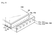
Fig. 1 is a perspective view for describing a structure of a lighting module according to an embodiment of the present invention, andFig. 2 is a cross sectional view for describing a structure of a lighting module according to an embodiment of the present invention. - Referring to
Fig.1 andFig.2 , alighting module 400 includes acase 200, a firstlight source unit 150A, a secondlight source unit 150B, a firstluminescent film 170a, a secondluminescent film 170b, alight guide plate 110, adiffusing plate 190, areflector 130, afirst connector 300A, and asecond connector 300B. - The
case 200 may be manufactured by assembling a plurality of flanges or may be manufactured in the form of a plate by using an extrusion molding method. A first and asecond seat case 200 by bending twice the both ends of the plate of the plate respectively asFig. 6a . The both ends of the plate face each other, and anopening 201 is defined by the both ends of the plate. Thecase 200 has a constant cross section of which both sides are parallel with each other in the longitudinal direction thereof. - In addition, the
case 200 may include at least one ormore projection 250a extended from one side. Such projection fixes and supports the light guide plate seated within the case. As a result, it can prevent displacement of the light guide plate due to external impact and improve alignment characteristic between internal structures of the case. - The first
light source unit 150A and the secondlight source unit 150B each have asubstrate light emitting diode sub-reflector second seat - Meanwhile, the end of the surface of the
sub-reflector light emitting diode substrate substrate substrate light emitting diode - The reason for this is to prevent the light reflected from the
light guide plate 110 from being irradiated onto thelight emitting diode light emitting diode light guide plate 110 through theluminescent film light guide plate 110 directly without theluminescent film light emitting diode light guide plate 110 back to thelight guide plate 110. Therefore, the optical efficiency of the lighting module will be improved. - The light emitting diodes included in the first
light source unit 150A and the secondlight source unit 150B emit a light with same color, but they may emit a light with different color. Therefore, creating light with various colors can be done by combination of two different colors, so that emotional lighting apparatus can be created. Thelight emitting diode - While not shown, translucent resin seal the light emitting diode at the top portion of the light emitting diode, so as to enable the light emitting diode to emit a light with its own color. However, when emitting a light with its own color, for example, when the light emitting device is blue light emitting diode, the fluorescent material included in the translucent resin may include at least one or more of a garnet based material (YAG, TAG), a silicate based material, a nitride based material, and an oxynitride based material.
- The natural light (white light) can be created by including a yellow fluorescent material in the translucent resin. However, it may further include a green fluorescent material or a red fluorescent material so as to increase the color rendering index and decrease color temperature.
- In addition, when various kinds of fluorescent material are mixed in the translucent resin, regarding the addition ratio according to the color of the fluorescent material, the green fluorescent material may used more than the red fluorescent material, and the yellow fluorescent material may used more than the green fluorescent material.
- YAG of a garnet based material, a silicate based material, and an oxynitride based material may be used as a yellow fluorescent material, a silicate based material and an oxynitride based material may be used as a green fluorescent material, and a nitride based material may be used as a red fluorescent material.
- Besides mixture of various kinds of fluorescent material, the translucent resin may consist of separately divided layers of a layer with a red fluorescent material, a layer with a green fluorescent material, and a yellow fluorescent material.
- Such a light emitting diode may be lateral type or vertical type, and may emit a light with blue, red, yellow, or green.
- Such fluorescent material may be applied to the first
luminescent film 170a, and the secondluminescent film 170b described later. - The
light guide plate 110 is placed along the direction of the path of the light emitted from the firstlight source unit 150A and the secondlight source unit 150B, and inserted within the case along the longitudinal direction of thecase 200. Here, the both ends of thelight guide plate 110 are inserted into the first and thesecond seat light source unit 150A and the secondlight source unit 150B toward theopening 201. - The first
luminescent film 170a and the secondluminescent film 170b is placed respectively between the firstlight source unit 150A and the secondlight source unit 150B, and include various fluorescent material inside. Such a firstluminescent film 170a and a secondluminescent film 170b may convert a part of the wavelength of the light emitted from the firstlight source unit 150A and the secondlight source unit 150B so as to convert the color of the light. - While not shown, the first
luminescent film 170a and the secondluminescent film 170b may include translucent resin and a fluorescent material contained within the translucent resin. A curing agent or an additive agent may be included within the transparent resin. The curing agent cures the transparent resin. The additive agent disperses uniformly the fluorescent material within the transparent resin. A diffusing agent may be included within the transparent resin. The diffusing agent improves the refractive index of a light source, thus increasing the excitation ratio of the fluorescent material. - The
light diffusing plate 190 is placed between thelight guide plate 110 and theopening 201 and inserted within thecase 200 to diffuse and emit the light emitted from thelight guide plate 110. Here, the both ends of the diffusingplate 190 are inserted into the first and thesecond seat plate 190 is substantially aligned with the end of thelight guide plate 110. The reason for this is to have a stable support structure among thelight guide plate 110, theluminescent film plate 190, and the sub-reflector 153a, 153b. That is because the end of the diffusing plate is contact with the end of the sub-reflector and the end of the light guide plate is contact with the luminescent film at a same time so as to substantially fix each element stably. - In addition, it is to irradiate the irradiated light to the
light guide plate 100 and the diffusingplate 190 and emit the irradiated light to theopening 201 without optical loss due to irradiation to the case when the end of the diffusingplate 190 is substantially contact with at least the sub-reflector and the light emitted from the light emitting diode is irradiated onto thelight guide plate 100 through the luminescent film or is irradiated onto the light guide plate directly without the luminescent film. As a result, the optical efficiency characteristic is improved. - The
reflector 130 is placed above thelight guide plate 110, reflects the emitted light from thelight guide plate 110 to the direction to the diffusingplate 190, and the both ends of thereflector 130 is inserted into the first and thesecond seat light guide plate 110, theluminescent film plate 190, the sub-reflector 153a, 153b, and thereflector 130. Such a reflector may be omitted from a lighting module if the reflection characteristic of the inner surface of the case is good. - The
first connector 300A and thesecond connector 300B are disposed on the external side face of thecase 200. The external side face of the case can be an external side face of abase portion 250 of the case or an external side face of a first and the second extendingportion Fig. 4 . However it is desirable that thefirst connector 300A and thesecond connector 300B are disposed on the external side face of thebase portion 250 of the case along the longitudinal direction of the case at the middle of the both ends. Thefirst connector 300A and thesecond connector 300B respectively include a plurality ofconnection pins external case - At least one of such a
first connector 300A and asecond connector 300B functions as connection member to connect with anotherlighting module 400 including thecase 200. As such, because the lighting module according to the embodiment of the present invention consists of a single module to emit a light, the lighting module itself can be used as a lighting apparatus. Alternatively, thefirst connector 300A and/or thesecond connector 300B may be electrically connected to an external power supply. -
Fig. 3 is an embodiment of the present invention for describing optical efficiency according to allocation structure of a sub-reflector. - Referring to
Fig. 3 , the emitted light from thelight emitting diode 152a is irradiated onto the direction to thelight guide plate 110 with an orientation angle. Here, the sub-reflector 153a is placed to protrude from the substrate with predetermined distance so as to irradiate 90% of the emitted light to the light guide plate directly. That is, most of the emitted light from the light emitting diode is not irradiated onto the sub-reflector 153 covering the light emitting diode disposed on thesubstrate 151a. - Therefore, because most of the light emitted from the light emitting diode is not irradiated onto the sub-reflector, and the sub-reflector prevents the light irradiated onto the light guide plate from reflecting and irradiating onto the light emitting diode in advance and reflects the light back to the light guide plate, the optical efficiency can be improved.
- In addition, the light having an outermost orientation angle among the light emitted from the light emitting diode is not irradiated onto the sub-reflector but is irradiated onto the light guide plate directly so as to maximize the optical efficiency.
- Meanwhile, when a single lighting module is used as a lighting apparatus, one of the first connector and the second connector can be an electrical connection path supplying power to the lighting module, however, when a plurality of lighting modules placed and connected in a line, the connector disposed on the end of the case of the lighting module placed outermost can be an electrical connection path supplying power.
- As a result, a plurality of lighting modules becomes a lighting apparatus so as to enlarging the light emitting range. In addition, because the lighting module according to the embodiment of the present invention consists of a single module to emit a light, the lighting module itself can be used as a lighting apparatus.
-
Fig. 4 is an embodiment of the present invention for describing a connection structure of a plurality of lighting modules, andFig. 5 is an embodiment of the present invention for describing an intermediate connection member to connect a plurality of lighting modules. - In
Fig. 4 andFig. 5 , one side of a first lighting module and a second lighting module of the lighting apparatus are contacted and connected to each other. Because the structures of the first lighting module and the second lighting module are described above, descriptions of them are omitted. Thefirst connector 300A disposed on the outside of the base portion of thecase 200 included in the first lighting module and thesecond connector 300B disposed on the external side face of the base portion of the case 200' included in the second lighting module are connected with theintermediate connection member 500. - The
intermediate connection member 500 has afirst insertion recess 511 and a second insertion recess 511', and afirst connection recess 513 and a second connection recess 513' formed within thefirst insertion recess 511 and the second insertion recess 511' respectively. Anouter case 303a and aconnection pin 301a of thefirst connector 300A are inserted into thefirst insertion recess 511 and thefirst connection recess 513 respectively, and anouter case 303b' and aconnection pin 301b' of the second connector are inserted into the second insertion recess 511' and the second connection recess 513' respectively so as to mechanically connect and fix the first lighting module and the second lighting module. -
Fig. 6a and 6b are embodiments of the present invention for describing a structure of a case. - As shown in
Fig. 6a , thecase 200 includes a first and a second extendingportion first flange portion 230a and asecond flange portion 230b bent and extended respectively from a side of the first and the second extendingportion base portion 250 bent and extended from the first extendingportion 210a and connected to the other side of the second extendingportion 210b. - As a result, the first and the
second seat case 200, and thefirst flange portion 230a and thesecond flange portion 230b face each other with a distance so as to have theopening 201. - In addition, like
Fig. 6b , thebase portion 250 of thecase 200 has one ormore projection 250a extended from the internal side face, and theprojection 250a increase an adhesion force among the reflector, the light guide plate, and the diffusing plate so as to fix and support the structures more stably. Theprojection 250a may have a line shape along the longitudinal direction of the case. In addition, theprojection 250a may have a dot shape locally arranged at the front side of the base portion of the case. That is to say, theprojection 250a is disposed along the longitudinal direction of thecase 200 or spot wise. - The
first flange portion 230a and thesecond flange portion 230b are extended and bent along the direction parallel to thebase portion 250 with respect to the first and the second extendingportion first flange portion 230a and thesecond flange portion 230b are bent at an acute angle (θ<90). Therefore, it is possible to fix and support more the structure inserted into thefirst seat 202a and thesecond seat 202b, i.e. the diffusing plate, the light guide plate, and the reflector. - In addition, the material of the
case 200 can be metal, for example, aluminum or iron, and it is more desirable that the case can have elasticity. - In the embodiment of the present invention described above, for convenience sake of the description, the device including the first
light source unit 150A, the secondlight source unit 150B, the firstluminescent film 170a, the secondluminescent film 170b, thelight guide plate 110, the diffusingplate 190, and thereflector 130 is referred to as a light source module. -
Fig. 7 is an embodiment of the present invention for describing a structure and a principle of operation of a light source module placed within a case. - As shown in the figure, the
light source module 100 includes thelight guide plate 110, thereflector 130, thelight source unit luminescent film plate 190. - The
light guide plate 110 converts a point light source into a surface light source, and aspecific pattern 111 is formed on a side so as to emit the light incident on the inside to the outside. Thespecific pattern 111 functions to diffuse or scatter the light and to emit the light to the outside. Such a light guide plate is made of transparent resin, and can be printed through the silk screen process. - The diffusing
plate 190 can be placed above thelight guide plate 110. The diffusing plate functions to uniformly emit the light incident on the inside of thelight guide plate 110. - The
reflector 130 is placed below thelight guide plate 110, and prevents the light incident on the inside of thelight guide plate 110 from emitting rearward of the light guide plate. - The
light source unit light guide plate 110. Thelight source unit light emitting diode light source unit substrate light emitting diodes substrate light source unit light guide plate 110. - The
luminescent film light guide plate 110 and thelight source unit luminescent film light source unit - While not shown, the
light source unit luminescent film seat case 200 described in theFig. 2 . In addition, the both respective ends of thelight guide plate 110, the diffusingplate 190, and thereflector 130 are placed to be inserted into theseat case 200. -
Fig. 8 is an embodiment of the present invention for describing the structure of a lighting module. - As shown in the figure, the lighting module includes the
case 200 including the light source module inside thereof and aend cap 350 connected to the both ends of thecase 200 and bent and extended along the opposite direction the light is irradiated. - The
case 200 has aheat radiating groove 200a formed on a side of thebase portion 250, and theend cap 350 has aprojection 351 on an end thereof. Thecase 200 has a receivingrecess 351a corresponding to theprojection 351, and the end cap has arecess 350a. - The
base portion 250 of the case may have a convex shape to enlarge the surface area of a side of the base portion for effective heat radiating of the inner light source. - The
end cap 350 bent and extended rearward is connected to the both ends of thecase 200. It is desirable that theend cap 350 is bent at a right angle, and is formed continuously to connect with thecase 200. In the embodiment, theheat radiating groove 200a is formed continuously to connect with a side of thecase 200, and the size of theend cap 350 is the same as a side face of thecase 200. - The
projection 351 is disposed on the side connected to thecase 200 of theend cap 350, and can be connected to thecorresponding receiving recess 351a disposed on the front, rear, and side face of thecase 200 by insertion. In addition, theend cap 350 has therecess 350a so as to be used for various attachments to the wall or ceiling. -
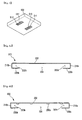
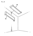
Fig. 9 is showing installation status of alighting module 400 according to the present invention, and the lighting module can be installed to the surface of a wall or ceiling. Here, the installed surface and thecase 200 or thelighting module 400 are a predetermined distant apart by theend cap 350 being bent towards the rear side of thelighting module 400. Especially when thelighting module 400 according to the present embodiment is installed to the surface of a wall, the secured space as such can be used for placing a ballast stabilizer or can include heat radiating structure having a volume not exceeding the space to help heat radiation of the inner light source of thelighting module 400. In addition, the lighting module can be installed to the ceiling in pendent form asFig. 10 . - As the occasion demand, a plurality of the
lighting modules 400 can be connected by using predetermined connection member (not shown) and a receivingrecess 351a, and can be used as an extended form by connecting theend cap 350 to the both ends when it reached the intended length.
Claims (7)
- A lighting module (400) comprising:a case (200) including an opening (201) where in use a light emits from, a base portion with two pairs of two opposed sides (250), and seats (202a, 202b) on one pair of the two opposed sides of the base portion (250);light source units (150A, 150B) disposed in the seats (202a, 202b);a light guide plate (110) placed within the case (200) and optically connected with the light source units (150A, 150B), wherein the light guide plate (110) is inserted into the seats (202a, 202b) and emits light from the light source units (150A, 150B) toward the opening (201);a diffusing plate (190) placed within the case (200), between the light guide plate (110) and the opening (201);an end cap (3 50) connected with each end of the case (200) these ends being located at the other one of the two pairs of two opposed sides of the base.characterized in that a protrusion (351) at a side of the end cap (350) is inserted in a receiving recess (351a) formed on the opposed sides of the case (200) and in that the end cap (350) is bent to extend along the opposite direction the light is irradiated.
- The lighting module of claim 1, wherein the case (200) includes
a first and a second extending portion (210a, 210b) respectively extended from the both ends of the base portion (250) on one pair of the two opposed sides; along a normal of the base surface and
a first and a second flange portion (230a, 230b) respectively extended from the ends of the first and the second extending portion (210a, 210b) to form the seats. - The lighting module of claim 2, wherein a face of the first and the second flange portion (230a, 230b) of the case are bent at an acute angle with respect to the first and the second extending portions (210a, 210b).
- The lighting module according to any preceding claims, wherein one side of the base portion (250) includes at least one connector (300A, 300B) electrically connected to an external power supply or connected to another lighting module.
- The lighting module according to any preceding claims, further comprising a luminescent film (170A, 170B) placed between the light source unit (150A, 150B) and the light guide plate (110).
- The lighting module according to any preceeding claims, wherein the light source unit (150A, 150B) is adapted to emit blue or white light.
- A lighting apparatus comprising: at least one lighting module according to any one of the preceding claims.
Priority Applications (1)
| Application Number | Priority Date | Filing Date | Title |
|---|---|---|---|
| EP13174944.2A EP2648024B1 (en) | 2010-04-10 | 2011-04-06 | Lighting module and lighting apparatus including the same |
Applications Claiming Priority (5)
| Application Number | Priority Date | Filing Date | Title |
|---|---|---|---|
| KR1020100033031A KR101694996B1 (en) | 2010-04-10 | 2010-04-10 | Lighting Device |
| KR1020100033051A KR101652833B1 (en) | 2010-04-10 | 2010-04-10 | Lighting device |
| KR1020100033030A KR101652012B1 (en) | 2010-04-10 | 2010-04-10 | Lighting Module |
| KR1020100092982A KR101798565B1 (en) | 2010-09-27 | 2010-09-27 | Lighting Module |
| KR1020100122751A KR101810920B1 (en) | 2010-12-03 | 2010-12-03 | Lighting Module |
Related Child Applications (2)
| Application Number | Title | Priority Date | Filing Date |
|---|---|---|---|
| EP13174944.2A Division EP2648024B1 (en) | 2010-04-10 | 2011-04-06 | Lighting module and lighting apparatus including the same |
| EP13174944.2 Division-Into | 2013-07-03 |
Publications (3)
| Publication Number | Publication Date |
|---|---|
| EP2375137A2 EP2375137A2 (en) | 2011-10-12 |
| EP2375137A3 EP2375137A3 (en) | 2011-11-02 |
| EP2375137B1 true EP2375137B1 (en) | 2013-08-28 |
Family
ID=44201096
Family Applications (2)
| Application Number | Title | Priority Date | Filing Date |
|---|---|---|---|
| EP13174944.2A Active EP2648024B1 (en) | 2010-04-10 | 2011-04-06 | Lighting module and lighting apparatus including the same |
| EP11161333.7A Active EP2375137B1 (en) | 2010-04-10 | 2011-04-06 | Lighting module and lighting apparatus including the same |
Family Applications Before (1)
| Application Number | Title | Priority Date | Filing Date |
|---|---|---|---|
| EP13174944.2A Active EP2648024B1 (en) | 2010-04-10 | 2011-04-06 | Lighting module and lighting apparatus including the same |
Country Status (4)
| Country | Link |
|---|---|
| US (2) | US8231258B2 (en) |
| EP (2) | EP2648024B1 (en) |
| JP (2) | JP5755484B2 (en) |
| CN (2) | CN102252180A (en) |
Families Citing this family (56)
| Publication number | Priority date | Publication date | Assignee | Title |
|---|---|---|---|---|
| US8231258B2 (en) * | 2010-04-10 | 2012-07-31 | Lg Innotek Co., Ltd. | Lighting module and lighting apparatus including the same |
| US9563008B2 (en) | 2010-09-17 | 2017-02-07 | Lg Innotek Co., Ltd. | Lighting module and lighting apparatus including the same |
| EP2431654B1 (en) * | 2010-09-17 | 2018-11-14 | LG Innotek Co., Ltd. | Lighting module and lighting apparatus including the same |
| US8192051B2 (en) * | 2010-11-01 | 2012-06-05 | Quarkstar Llc | Bidirectional LED light sheet |
| US8314566B2 (en) | 2011-02-22 | 2012-11-20 | Quarkstar Llc | Solid state lamp using light emitting strips |
| US8410726B2 (en) | 2011-02-22 | 2013-04-02 | Quarkstar Llc | Solid state lamp using modular light emitting elements |
| EP2753977B1 (en) * | 2011-09-09 | 2019-11-06 | LG Innotek Co., Ltd. | Back light unit within resin layer for light-guide |
| JP5716623B2 (en) * | 2011-09-27 | 2015-05-13 | 豊田合成株式会社 | Linear light source device and planar light source device |
| FR2981434B1 (en) * | 2011-10-14 | 2017-12-01 | Oya Sourcing | LAMP |
| CN103574355B (en) * | 2012-08-10 | 2017-11-17 | Lg伊诺特有限公司 | Lighting device |
| US9188318B2 (en) * | 2012-09-12 | 2015-11-17 | Cooper Technologies Company | Light-emitting diode wave guide down light retrofit fixtures |
| WO2014043138A1 (en) | 2012-09-12 | 2014-03-20 | Cooper Technologies Company | Light-emitting diode light retrofit fixtures |
| JP2014063600A (en) | 2012-09-20 | 2014-04-10 | Mitsubishi Electric Corp | Linear light source device |
| CN103836438A (en) * | 2012-11-21 | 2014-06-04 | 深圳市海洋王照明工程有限公司 | Lamp |
| CN103836436A (en) * | 2012-11-21 | 2014-06-04 | 深圳市海洋王照明工程有限公司 | Lamp |
| CN103104843B (en) * | 2013-01-24 | 2015-03-25 | 杭州纳晶照明技术有限公司 | Lighting device |
| US9291320B2 (en) | 2013-01-30 | 2016-03-22 | Cree, Inc. | Consolidated troffer |
| US9690029B2 (en) | 2013-01-30 | 2017-06-27 | Cree, Inc. | Optical waveguides and luminaires incorporating same |
| US9869432B2 (en) | 2013-01-30 | 2018-01-16 | Cree, Inc. | Luminaires using waveguide bodies and optical elements |
| US9366396B2 (en) | 2013-01-30 | 2016-06-14 | Cree, Inc. | Optical waveguide and lamp including same |
| US9442243B2 (en) | 2013-01-30 | 2016-09-13 | Cree, Inc. | Waveguide bodies including redirection features and methods of producing same |
| US9625638B2 (en) | 2013-03-15 | 2017-04-18 | Cree, Inc. | Optical waveguide body |
| US9519095B2 (en) | 2013-01-30 | 2016-12-13 | Cree, Inc. | Optical waveguides |
| EP2767753A1 (en) * | 2013-02-18 | 2014-08-20 | LD Lichtdominanz GmbH | Light panel operating on the basis of light-emitting diode chips |
| US10436970B2 (en) | 2013-03-15 | 2019-10-08 | Ideal Industries Lighting Llc | Shaped optical waveguide bodies |
| US9366799B2 (en) | 2013-03-15 | 2016-06-14 | Cree, Inc. | Optical waveguide bodies and luminaires utilizing same |
| US10502899B2 (en) * | 2013-03-15 | 2019-12-10 | Ideal Industries Lighting Llc | Outdoor and/or enclosed structure LED luminaire |
| US9798072B2 (en) | 2013-03-15 | 2017-10-24 | Cree, Inc. | Optical element and method of forming an optical element |
| US10400984B2 (en) | 2013-03-15 | 2019-09-03 | Cree, Inc. | LED light fixture and unitary optic member therefor |
| US10209429B2 (en) | 2013-03-15 | 2019-02-19 | Cree, Inc. | Luminaire with selectable luminous intensity pattern |
| US9920901B2 (en) | 2013-03-15 | 2018-03-20 | Cree, Inc. | LED lensing arrangement |
| US9645303B2 (en) | 2013-03-15 | 2017-05-09 | Cree, Inc. | Luminaires utilizing edge coupling |
| US10379278B2 (en) * | 2013-03-15 | 2019-08-13 | Ideal Industries Lighting Llc | Outdoor and/or enclosed structure LED luminaire outdoor and/or enclosed structure LED luminaire having outward illumination |
| US10036517B2 (en) * | 2013-05-16 | 2018-07-31 | 3M Innovative Properties Company | Lightguide as luminaire |
| CN104676500A (en) * | 2013-11-26 | 2015-06-03 | 潘文莘 | Light guide unit and light emitting device having the same |
| USD751237S1 (en) * | 2014-04-30 | 2016-03-08 | Pinnacle Architectural Lighting | Suspended light fixture |
| EP3179832B1 (en) * | 2014-08-08 | 2018-09-12 | Kaneka Corporation | Planar light-emitting panel and elastic jacket |
| USD799099S1 (en) * | 2015-03-31 | 2017-10-03 | Artemide S.P.A. | Lighting fixture |
| USD782722S1 (en) * | 2015-07-20 | 2017-03-28 | Hubbardton Forge, Llc. | Lamp |
| US9964692B2 (en) * | 2015-10-06 | 2018-05-08 | Focal Point, Llc | Illuminated feature for an LED luminaire |
| CN106885186B (en) * | 2015-12-15 | 2019-03-15 | 瑞仪光电(苏州)有限公司 | Lamps and lanterns |
| US11759993B2 (en) | 2016-01-20 | 2023-09-19 | Nissan Ringel | Panel device and method of manufacturing |
| US20190261788A1 (en) * | 2016-01-20 | 2019-08-29 | Nissan Ringel | Lighting Units |
| US11719882B2 (en) | 2016-05-06 | 2023-08-08 | Ideal Industries Lighting Llc | Waveguide-based light sources with dynamic beam shaping |
| US10416377B2 (en) | 2016-05-06 | 2019-09-17 | Cree, Inc. | Luminaire with controllable light emission |
| CN206975364U (en) * | 2016-07-22 | 2018-02-06 | 矽创电子股份有限公司 | Display device and its back lighting device of tool light path bending |
| US11680699B2 (en) | 2018-10-12 | 2023-06-20 | Radiant Opto-Electronics (Suzhou) Co., Ltd. | Lamp, lamp system, method for assembling lamp system, and method for disassembling lamp system |
| EP3865759A4 (en) * | 2018-10-12 | 2022-03-09 | Radiant Opto-electronics (Suzhou) Co., Ltd. | Lamp, lamp system, and assembly method for lamp system |
| US10775018B1 (en) * | 2019-09-17 | 2020-09-15 | Abl Ip Holding Llc | Direct/indirect luminaire systems and methods |
| CN110675741B (en) * | 2019-09-29 | 2021-10-08 | 厦门天马微电子有限公司 | Backlight module and display device |
| NL2024980B1 (en) * | 2020-02-24 | 2021-10-14 | Schreder Sa | Modular luminaire assemblies for tunnels |
| EP3875840B1 (en) * | 2020-03-03 | 2022-06-29 | Prosperous (Ningbo) Lighting Appliance Co., Ltd. | Independent and spliceable cabinet lamp |
| CN111750321A (en) * | 2020-06-24 | 2020-10-09 | 上海摩勤智能技术有限公司 | Luminous assembly, shell and electronic equipment |
| WO2022001956A1 (en) * | 2020-06-29 | 2022-01-06 | 苏州欧普照明有限公司 | Lighting fixture |
| TWI749713B (en) * | 2020-08-14 | 2021-12-11 | 群光電能科技股份有限公司 | Backlight module and illuminated touch device thereof |
| WO2022116928A1 (en) * | 2020-12-04 | 2022-06-09 | 苏州欧普照明有限公司 | Illumination lamp |
Family Cites Families (44)
| Publication number | Priority date | Publication date | Assignee | Title |
|---|---|---|---|---|
| DE19644875A1 (en) | 1996-10-29 | 1998-04-30 | Willing Gmbh Dr Ing | Flat disc-like lamp with large-area light-radiating surfaces e.g. for walls, floors or ceilings |
| DE19755658A1 (en) | 1997-12-15 | 1999-06-17 | Zumtobel Staff Gmbh | Luminaire with a disc-shaped light guide |
| JP3114805B2 (en) * | 1998-04-15 | 2000-12-04 | 日亜化学工業株式会社 | Planar light source, display backlight using the same, and illuminated operation switch |
| JP2000207917A (en) * | 1999-01-14 | 2000-07-28 | Samsung Electronics Co Ltd | Backlight assembly for liquid crystal display device module |
| JP3792498B2 (en) * | 2000-10-26 | 2006-07-05 | 株式会社エンプラス | Surface light source device and image display device |
| EP1346178B1 (en) | 2000-12-22 | 2004-11-03 | Thomas Emde | Sandwich-like panel element |
| JP2003203515A (en) * | 2002-01-09 | 2003-07-18 | Sharp Corp | Luminaire, its designing method, its manufacturing method, display device, and light guiding body |
| JP4130100B2 (en) * | 2002-07-05 | 2008-08-06 | アルプス電気株式会社 | Surface light emitting device and liquid crystal display device |
| AU2002335410A1 (en) * | 2002-09-19 | 2004-04-08 | Matsushita Electric Industrial Co., Ltd. | Illumination unit and liquid crystal display comprising it |
| KR100962641B1 (en) * | 2003-07-07 | 2010-06-11 | 삼성전자주식회사 | Backlight assembly, liquid crystal display device having the same, and method of manufacturing the backlight assembly |
| JP2005339881A (en) * | 2004-05-25 | 2005-12-08 | Hitachi Displays Ltd | Lighting device, lighting module, and liquid crystal display |
| CN100395623C (en) * | 2005-06-10 | 2008-06-18 | 清华大学 | Back light module |
| TWI288852B (en) * | 2005-07-22 | 2007-10-21 | Innolux Display Corp | Backlight module and liquid crystal display device using the same |
| WO2007049847A1 (en) * | 2005-10-26 | 2007-05-03 | Fawoo Technology Co., Ltd. | Backlight unit capable of easily forming curved and three-dimensional shape |
| KR20080063786A (en) * | 2005-10-28 | 2008-07-07 | 타키론 가부시기가이샤 | Surface-emitting device and light-emitting method for surface-emitting device |
| US20070127144A1 (en) * | 2005-12-06 | 2007-06-07 | Eastman Kodak Company | Optical film and frame with high resistance to thermal distortion |
| US7547112B2 (en) | 2005-12-12 | 2009-06-16 | Led Folio Corporation | Low-clearance light emitting diode lighting |
| DE602006020486D1 (en) * | 2005-12-16 | 2011-04-14 | Koninkl Philips Electronics Nv | COMPATIBLE LIGHTING MODULES COMPREHENSIVE LIGHTING SYSTEM |
| JP2007178797A (en) * | 2005-12-28 | 2007-07-12 | Optrex Corp | Liquid crystal display device |
| JP4659640B2 (en) * | 2006-02-24 | 2011-03-30 | オスラム・メルコ株式会社 | Lighting equipment using light-emitting diodes |
| WO2007115736A1 (en) | 2006-04-04 | 2007-10-18 | Thomas Emde | Illuminable panel arrangement |
| US20080037284A1 (en) | 2006-04-21 | 2008-02-14 | Rudisill Charles A | Lightguide tile modules and modular lighting system |
| JP4388042B2 (en) * | 2006-08-11 | 2009-12-24 | 勝華科技股▲ふん▼有限公司 | Liquid crystal display and its frame |
| JP2008066143A (en) * | 2006-09-07 | 2008-03-21 | Nidec Copal Corp | Surface light-emitting device |
| WO2008041185A2 (en) | 2006-10-05 | 2008-04-10 | Koninklijke Philips Electronics N.V. | Lighting device comprising a light tile with variable color temperature |
| JP2008175926A (en) * | 2007-01-17 | 2008-07-31 | Hitachi Displays Ltd | Liquid crystal display module |
| JP4973213B2 (en) * | 2007-01-31 | 2012-07-11 | 三菱電機株式会社 | Light source device, planar light source device, and display device |
| KR101283129B1 (en) * | 2007-04-03 | 2013-07-05 | 엘지이노텍 주식회사 | Light guide plate, surface light source apparatus and display apparatus having thereof |
| US20090010022A1 (en) * | 2007-07-03 | 2009-01-08 | Tsai Tzung-Shiun | Multi-functional led lamp |
| US20090086504A1 (en) | 2007-10-02 | 2009-04-02 | Led Folio Corporation | Backlit erasable writing board |
| JP2009117235A (en) * | 2007-11-08 | 2009-05-28 | Yamaha Motor Electronics Co Ltd | Backlight module, and digital meter |
| US7549784B1 (en) | 2007-12-06 | 2009-06-23 | New Horizon Designs, Inc. | LED lighting for glass tiles |
| JP5168626B2 (en) * | 2008-01-16 | 2013-03-21 | 日本精機株式会社 | Backlight device |
| JP2009199924A (en) * | 2008-02-22 | 2009-09-03 | Okamura Corp | Illuminating device |
| US20090237958A1 (en) | 2008-03-21 | 2009-09-24 | Led Folio Corporation | Low-clearance light-emitting diode lighting |
| JP5149668B2 (en) * | 2008-03-26 | 2013-02-20 | パナソニック株式会社 | Lighting fixture mounting device |
| CN101603665A (en) * | 2008-06-13 | 2009-12-16 | 先进开发光电股份有限公司 | LED light-source module |
| EP2161600A1 (en) * | 2008-09-09 | 2010-03-10 | TPO Displays Corp. | Liquid crystal display device containing a light guide |
| DE102008047010A1 (en) | 2008-09-12 | 2010-03-18 | Zumtobel Lighting Gmbh | System for brightening the ceiling of a room |
| TWI394921B (en) | 2008-09-22 | 2013-05-01 | Sinology Entpr Ltd | Structure of a modular advertising-box and structure of a modular lighting thereof |
| CN101684926A (en) * | 2008-09-26 | 2010-03-31 | 上海莹亮照明科技有限公司 | LED light guide plate |
| CN201434302Y (en) * | 2009-05-07 | 2010-03-31 | 陈铿胜 | High-mounted brake light |
| CN201425205Y (en) * | 2009-05-21 | 2010-03-17 | 潘文莘 | Luminescent diode lighting device and lighting module capable of generating even strip-shaped light source |
| US8231258B2 (en) * | 2010-04-10 | 2012-07-31 | Lg Innotek Co., Ltd. | Lighting module and lighting apparatus including the same |
-
2011
- 2011-04-05 US US13/080,440 patent/US8231258B2/en not_active Expired - Fee Related
- 2011-04-06 EP EP13174944.2A patent/EP2648024B1/en active Active
- 2011-04-06 EP EP11161333.7A patent/EP2375137B1/en active Active
- 2011-04-08 JP JP2011085860A patent/JP5755484B2/en not_active Expired - Fee Related
- 2011-04-11 CN CN2011100923821A patent/CN102252180A/en active Pending
- 2011-04-11 CN CN201510555698.8A patent/CN105065952B/en active Active
-
2012
- 2012-05-15 US US13/471,967 patent/US8382354B2/en active Active
-
2015
- 2015-05-27 JP JP2015107785A patent/JP6189361B2/en active Active
Also Published As
| Publication number | Publication date |
|---|---|
| JP6189361B2 (en) | 2017-08-30 |
| EP2375137A2 (en) | 2011-10-12 |
| EP2648024A2 (en) | 2013-10-09 |
| US20110205758A1 (en) | 2011-08-25 |
| CN105065952A (en) | 2015-11-18 |
| EP2648024A3 (en) | 2014-01-08 |
| JP2011222516A (en) | 2011-11-04 |
| JP5755484B2 (en) | 2015-07-29 |
| EP2648024B1 (en) | 2022-10-26 |
| CN102252180A (en) | 2011-11-23 |
| EP2375137A3 (en) | 2011-11-02 |
| US8382354B2 (en) | 2013-02-26 |
| US8231258B2 (en) | 2012-07-31 |
| JP2015179681A (en) | 2015-10-08 |
| US20120224392A1 (en) | 2012-09-06 |
| CN105065952B (en) | 2019-01-11 |
Similar Documents
| Publication | Publication Date | Title |
|---|---|---|
| EP2375137B1 (en) | Lighting module and lighting apparatus including the same | |
| US11703631B2 (en) | Illumination devices including multiple light emitting elements | |
| US20240151895A1 (en) | Illumination devices including multiple light emitting elements | |
| WO2010001604A1 (en) | Illumination device | |
| CN102410452B (en) | Lighting module and lighting apparatus including same | |
| JP2017037856A (en) | Lighting device | |
| JP6446202B2 (en) | Wide-angle diffusion optical system and illumination device using the same | |
| EP2314911A2 (en) | Light source apparatus | |
| JP2007234385A (en) | Backlight device | |
| CN104822986B (en) | Use the light emitting device of light guide | |
| US20110285268A1 (en) | Light-emitting device | |
| KR20220098713A (en) | Lighting apparatus | |
| KR101683586B1 (en) | Connecting apparatus for lighting module and lighting apparatus comprising the same | |
| TW201411045A (en) | Lighting apparatus and lighting apparatus unit using the same | |
| KR101810920B1 (en) | Lighting Module | |
| KR101652012B1 (en) | Lighting Module | |
| JP6659918B2 (en) | Solid state light emitter lighting assembly and luminaire | |
| KR101815135B1 (en) | Lighting Module | |
| KR101694996B1 (en) | Lighting Device | |
| KR101798565B1 (en) | Lighting Module | |
| KR101272689B1 (en) | Lighting module | |
| KR20120052525A (en) | Lighting module | |
| KR20160028151A (en) | Lighting reflector and plane lighting apparatus using thereof | |
| TW201439463A (en) | LED ceiling lamp structure for increasing lighting effect |
Legal Events
| Date | Code | Title | Description |
|---|---|---|---|
| PUAI | Public reference made under article 153(3) epc to a published international application that has entered the european phase |
Free format text: ORIGINAL CODE: 0009012 |
|
| PUAL | Search report despatched |
Free format text: ORIGINAL CODE: 0009013 |
|
| 17P | Request for examination filed |
Effective date: 20110406 |
|
| AK | Designated contracting states |
Kind code of ref document: A2 Designated state(s): AL AT BE BG CH CY CZ DE DK EE ES FI FR GB GR HR HU IE IS IT LI LT LU LV MC MK MT NL NO PL PT RO RS SE SI SK SM TR |
|
| AX | Request for extension of the european patent |
Extension state: BA ME |
|
| AK | Designated contracting states |
Kind code of ref document: A3 Designated state(s): AL AT BE BG CH CY CZ DE DK EE ES FI FR GB GR HR HU IE IS IT LI LT LU LV MC MK MT NL NO PL PT RO RS SE SI SK SM TR |
|
| AX | Request for extension of the european patent |
Extension state: BA ME |
|
| RIC1 | Information provided on ipc code assigned before grant |
Ipc: F21S 10/00 20060101AFI20110928BHEP Ipc: G02B 6/00 20060101ALI20110928BHEP |
|
| 17Q | First examination report despatched |
Effective date: 20120717 |
|
| GRAP | Despatch of communication of intention to grant a patent |
Free format text: ORIGINAL CODE: EPIDOSNIGR1 |
|
| GRAS | Grant fee paid |
Free format text: ORIGINAL CODE: EPIDOSNIGR3 |
|
| GRAA | (expected) grant |
Free format text: ORIGINAL CODE: 0009210 |
|
| AK | Designated contracting states |
Kind code of ref document: B1 Designated state(s): AL AT BE BG CH CY CZ DE DK EE ES FI FR GB GR HR HU IE IS IT LI LT LU LV MC MK MT NL NO PL PT RO RS SE SI SK SM TR |
|
| REG | Reference to a national code |
Ref country code: GB Ref legal event code: FG4D |
|
| REG | Reference to a national code |
Ref country code: CH Ref legal event code: EP |
|
| REG | Reference to a national code |
Ref country code: AT Ref legal event code: REF Ref document number: 629565 Country of ref document: AT Kind code of ref document: T Effective date: 20130915 |
|
| REG | Reference to a national code |
Ref country code: IE Ref legal event code: FG4D |
|
| REG | Reference to a national code |
Ref country code: DE Ref legal event code: R096 Ref document number: 602011002779 Country of ref document: DE Effective date: 20131024 |
|
| REG | Reference to a national code |
Ref country code: NL Ref legal event code: T3 |
|
| REG | Reference to a national code |
Ref country code: AT Ref legal event code: MK05 Ref document number: 629565 Country of ref document: AT Kind code of ref document: T Effective date: 20130828 |
|
| REG | Reference to a national code |
Ref country code: LT Ref legal event code: MG4D |
|
| PG25 | Lapsed in a contracting state [announced via postgrant information from national office to epo] |
Ref country code: IS Free format text: LAPSE BECAUSE OF FAILURE TO SUBMIT A TRANSLATION OF THE DESCRIPTION OR TO PAY THE FEE WITHIN THE PRESCRIBED TIME-LIMIT Effective date: 20131228 Ref country code: SE Free format text: LAPSE BECAUSE OF FAILURE TO SUBMIT A TRANSLATION OF THE DESCRIPTION OR TO PAY THE FEE WITHIN THE PRESCRIBED TIME-LIMIT Effective date: 20130828 Ref country code: NO Free format text: LAPSE BECAUSE OF FAILURE TO SUBMIT A TRANSLATION OF THE DESCRIPTION OR TO PAY THE FEE WITHIN THE PRESCRIBED TIME-LIMIT Effective date: 20131128 Ref country code: HR Free format text: LAPSE BECAUSE OF FAILURE TO SUBMIT A TRANSLATION OF THE DESCRIPTION OR TO PAY THE FEE WITHIN THE PRESCRIBED TIME-LIMIT Effective date: 20130828 Ref country code: LT Free format text: LAPSE BECAUSE OF FAILURE TO SUBMIT A TRANSLATION OF THE DESCRIPTION OR TO PAY THE FEE WITHIN THE PRESCRIBED TIME-LIMIT Effective date: 20130828 Ref country code: PT Free format text: LAPSE BECAUSE OF FAILURE TO SUBMIT A TRANSLATION OF THE DESCRIPTION OR TO PAY THE FEE WITHIN THE PRESCRIBED TIME-LIMIT Effective date: 20131230 Ref country code: CY Free format text: LAPSE BECAUSE OF FAILURE TO SUBMIT A TRANSLATION OF THE DESCRIPTION OR TO PAY THE FEE WITHIN THE PRESCRIBED TIME-LIMIT Effective date: 20130619 Ref country code: AT Free format text: LAPSE BECAUSE OF FAILURE TO SUBMIT A TRANSLATION OF THE DESCRIPTION OR TO PAY THE FEE WITHIN THE PRESCRIBED TIME-LIMIT Effective date: 20130828 |
|
| PG25 | Lapsed in a contracting state [announced via postgrant information from national office to epo] |
Ref country code: LV Free format text: LAPSE BECAUSE OF FAILURE TO SUBMIT A TRANSLATION OF THE DESCRIPTION OR TO PAY THE FEE WITHIN THE PRESCRIBED TIME-LIMIT Effective date: 20130828 Ref country code: BE Free format text: LAPSE BECAUSE OF FAILURE TO SUBMIT A TRANSLATION OF THE DESCRIPTION OR TO PAY THE FEE WITHIN THE PRESCRIBED TIME-LIMIT Effective date: 20130828 Ref country code: GR Free format text: LAPSE BECAUSE OF FAILURE TO SUBMIT A TRANSLATION OF THE DESCRIPTION OR TO PAY THE FEE WITHIN THE PRESCRIBED TIME-LIMIT Effective date: 20131129 Ref country code: PL Free format text: LAPSE BECAUSE OF FAILURE TO SUBMIT A TRANSLATION OF THE DESCRIPTION OR TO PAY THE FEE WITHIN THE PRESCRIBED TIME-LIMIT Effective date: 20130828 Ref country code: SI Free format text: LAPSE BECAUSE OF FAILURE TO SUBMIT A TRANSLATION OF THE DESCRIPTION OR TO PAY THE FEE WITHIN THE PRESCRIBED TIME-LIMIT Effective date: 20130828 Ref country code: FI Free format text: LAPSE BECAUSE OF FAILURE TO SUBMIT A TRANSLATION OF THE DESCRIPTION OR TO PAY THE FEE WITHIN THE PRESCRIBED TIME-LIMIT Effective date: 20130828 |
|
| PG25 | Lapsed in a contracting state [announced via postgrant information from national office to epo] |
Ref country code: CY Free format text: LAPSE BECAUSE OF FAILURE TO SUBMIT A TRANSLATION OF THE DESCRIPTION OR TO PAY THE FEE WITHIN THE PRESCRIBED TIME-LIMIT Effective date: 20130828 |
|
| PG25 | Lapsed in a contracting state [announced via postgrant information from national office to epo] |
Ref country code: RO Free format text: LAPSE BECAUSE OF FAILURE TO SUBMIT A TRANSLATION OF THE DESCRIPTION OR TO PAY THE FEE WITHIN THE PRESCRIBED TIME-LIMIT Effective date: 20130828 Ref country code: CZ Free format text: LAPSE BECAUSE OF FAILURE TO SUBMIT A TRANSLATION OF THE DESCRIPTION OR TO PAY THE FEE WITHIN THE PRESCRIBED TIME-LIMIT Effective date: 20130828 Ref country code: DK Free format text: LAPSE BECAUSE OF FAILURE TO SUBMIT A TRANSLATION OF THE DESCRIPTION OR TO PAY THE FEE WITHIN THE PRESCRIBED TIME-LIMIT Effective date: 20130828 Ref country code: SK Free format text: LAPSE BECAUSE OF FAILURE TO SUBMIT A TRANSLATION OF THE DESCRIPTION OR TO PAY THE FEE WITHIN THE PRESCRIBED TIME-LIMIT Effective date: 20130828 Ref country code: EE Free format text: LAPSE BECAUSE OF FAILURE TO SUBMIT A TRANSLATION OF THE DESCRIPTION OR TO PAY THE FEE WITHIN THE PRESCRIBED TIME-LIMIT Effective date: 20130828 |
|
| PG25 | Lapsed in a contracting state [announced via postgrant information from national office to epo] |
Ref country code: ES Free format text: LAPSE BECAUSE OF FAILURE TO SUBMIT A TRANSLATION OF THE DESCRIPTION OR TO PAY THE FEE WITHIN THE PRESCRIBED TIME-LIMIT Effective date: 20130828 Ref country code: IT Free format text: LAPSE BECAUSE OF FAILURE TO SUBMIT A TRANSLATION OF THE DESCRIPTION OR TO PAY THE FEE WITHIN THE PRESCRIBED TIME-LIMIT Effective date: 20130828 |
|
| REG | Reference to a national code |
Ref country code: DE Ref legal event code: R097 Ref document number: 602011002779 Country of ref document: DE |
|
| PLBE | No opposition filed within time limit |
Free format text: ORIGINAL CODE: 0009261 |
|
| STAA | Information on the status of an ep patent application or granted ep patent |
Free format text: STATUS: NO OPPOSITION FILED WITHIN TIME LIMIT |
|
| 26N | No opposition filed |
Effective date: 20140530 |
|
| REG | Reference to a national code |
Ref country code: DE Ref legal event code: R097 Ref document number: 602011002779 Country of ref document: DE Effective date: 20140530 |
|
| PG25 | Lapsed in a contracting state [announced via postgrant information from national office to epo] |
Ref country code: MC Free format text: LAPSE BECAUSE OF FAILURE TO SUBMIT A TRANSLATION OF THE DESCRIPTION OR TO PAY THE FEE WITHIN THE PRESCRIBED TIME-LIMIT Effective date: 20130828 Ref country code: LU Free format text: LAPSE BECAUSE OF FAILURE TO SUBMIT A TRANSLATION OF THE DESCRIPTION OR TO PAY THE FEE WITHIN THE PRESCRIBED TIME-LIMIT Effective date: 20140406 |
|
| REG | Reference to a national code |
Ref country code: CH Ref legal event code: PL |
|
| REG | Reference to a national code |
Ref country code: IE Ref legal event code: MM4A |
|
| PG25 | Lapsed in a contracting state [announced via postgrant information from national office to epo] |
Ref country code: CH Free format text: LAPSE BECAUSE OF NON-PAYMENT OF DUE FEES Effective date: 20140430 Ref country code: LI Free format text: LAPSE BECAUSE OF NON-PAYMENT OF DUE FEES Effective date: 20140430 |
|
| PG25 | Lapsed in a contracting state [announced via postgrant information from national office to epo] |
Ref country code: IE Free format text: LAPSE BECAUSE OF NON-PAYMENT OF DUE FEES Effective date: 20140406 |
|
| REG | Reference to a national code |
Ref country code: FR Ref legal event code: PLFP Year of fee payment: 6 |
|
| PG25 | Lapsed in a contracting state [announced via postgrant information from national office to epo] |
Ref country code: MT Free format text: LAPSE BECAUSE OF FAILURE TO SUBMIT A TRANSLATION OF THE DESCRIPTION OR TO PAY THE FEE WITHIN THE PRESCRIBED TIME-LIMIT Effective date: 20130828 |
|
| PG25 | Lapsed in a contracting state [announced via postgrant information from national office to epo] |
Ref country code: SM Free format text: LAPSE BECAUSE OF FAILURE TO SUBMIT A TRANSLATION OF THE DESCRIPTION OR TO PAY THE FEE WITHIN THE PRESCRIBED TIME-LIMIT Effective date: 20130828 |
|
| PG25 | Lapsed in a contracting state [announced via postgrant information from national office to epo] |
Ref country code: BG Free format text: LAPSE BECAUSE OF FAILURE TO SUBMIT A TRANSLATION OF THE DESCRIPTION OR TO PAY THE FEE WITHIN THE PRESCRIBED TIME-LIMIT Effective date: 20130828 Ref country code: RS Free format text: LAPSE BECAUSE OF FAILURE TO SUBMIT A TRANSLATION OF THE DESCRIPTION OR TO PAY THE FEE WITHIN THE PRESCRIBED TIME-LIMIT Effective date: 20130828 |
|
| PG25 | Lapsed in a contracting state [announced via postgrant information from national office to epo] |
Ref country code: HU Free format text: LAPSE BECAUSE OF FAILURE TO SUBMIT A TRANSLATION OF THE DESCRIPTION OR TO PAY THE FEE WITHIN THE PRESCRIBED TIME-LIMIT; INVALID AB INITIO Effective date: 20110406 Ref country code: TR Free format text: LAPSE BECAUSE OF FAILURE TO SUBMIT A TRANSLATION OF THE DESCRIPTION OR TO PAY THE FEE WITHIN THE PRESCRIBED TIME-LIMIT Effective date: 20130828 |
|
| REG | Reference to a national code |
Ref country code: FR Ref legal event code: PLFP Year of fee payment: 7 |
|
| PGFP | Annual fee paid to national office [announced via postgrant information from national office to epo] |
Ref country code: NL Payment date: 20170308 Year of fee payment: 7 Ref country code: FR Payment date: 20170309 Year of fee payment: 7 |
|
| PG25 | Lapsed in a contracting state [announced via postgrant information from national office to epo] |
Ref country code: MK Free format text: LAPSE BECAUSE OF FAILURE TO SUBMIT A TRANSLATION OF THE DESCRIPTION OR TO PAY THE FEE WITHIN THE PRESCRIBED TIME-LIMIT Effective date: 20130828 |
|
| PG25 | Lapsed in a contracting state [announced via postgrant information from national office to epo] |
Ref country code: AL Free format text: LAPSE BECAUSE OF FAILURE TO SUBMIT A TRANSLATION OF THE DESCRIPTION OR TO PAY THE FEE WITHIN THE PRESCRIBED TIME-LIMIT Effective date: 20130828 |
|
| REG | Reference to a national code |
Ref country code: NL Ref legal event code: MM Effective date: 20180501 |
|
| PG25 | Lapsed in a contracting state [announced via postgrant information from national office to epo] |
Ref country code: NL Free format text: LAPSE BECAUSE OF NON-PAYMENT OF DUE FEES Effective date: 20180501 |
|
| PG25 | Lapsed in a contracting state [announced via postgrant information from national office to epo] |
Ref country code: FR Free format text: LAPSE BECAUSE OF NON-PAYMENT OF DUE FEES Effective date: 20180430 |
|
| REG | Reference to a national code |
Ref country code: GB Ref legal event code: 732E Free format text: REGISTERED BETWEEN 20210722 AND 20210728 |
|
| REG | Reference to a national code |
Ref country code: DE Ref legal event code: R081 Ref document number: 602011002779 Country of ref document: DE Owner name: SUZHOU LEKIN SEMICONDUCTOR CO. LTD., TAICANG, CN Free format text: FORMER OWNER: LG INNOTEK CO., LTD., SEOUL/SOUL, KR |
|
| PGFP | Annual fee paid to national office [announced via postgrant information from national office to epo] |
Ref country code: GB Payment date: 20230309 Year of fee payment: 13 |
|
| PGFP | Annual fee paid to national office [announced via postgrant information from national office to epo] |
Ref country code: DE Payment date: 20230314 Year of fee payment: 13 |