EP2373538B1 - Transmission unit for a bicycle - Google Patents
Transmission unit for a bicycle Download PDFInfo
- Publication number
- EP2373538B1 EP2373538B1 EP09768451.8A EP09768451A EP2373538B1 EP 2373538 B1 EP2373538 B1 EP 2373538B1 EP 09768451 A EP09768451 A EP 09768451A EP 2373538 B1 EP2373538 B1 EP 2373538B1
- Authority
- EP
- European Patent Office
- Prior art keywords
- transmission
- transmission unit
- wheel hub
- input
- bicycle
- Prior art date
- Legal status (The legal status is an assumption and is not a legal conclusion. Google has not performed a legal analysis and makes no representation as to the accuracy of the status listed.)
- Active
Links
- 230000005540 biological transmission Effects 0.000 title claims description 123
- 230000004907 flux Effects 0.000 claims description 2
- 238000010276 construction Methods 0.000 description 5
Images

Classifications
-
- B—PERFORMING OPERATIONS; TRANSPORTING
- B62—LAND VEHICLES FOR TRAVELLING OTHERWISE THAN ON RAILS
- B62M—RIDER PROPULSION OF WHEELED VEHICLES OR SLEDGES; POWERED PROPULSION OF SLEDGES OR SINGLE-TRACK CYCLES; TRANSMISSIONS SPECIALLY ADAPTED FOR SUCH VEHICLES
- B62M6/00—Rider propulsion of wheeled vehicles with additional source of power, e.g. combustion engine or electric motor
- B62M6/40—Rider propelled cycles with auxiliary electric motor
- B62M6/60—Rider propelled cycles with auxiliary electric motor power-driven at axle parts
- B62M6/65—Rider propelled cycles with auxiliary electric motor power-driven at axle parts with axle and driving shaft arranged coaxially
-
- F—MECHANICAL ENGINEERING; LIGHTING; HEATING; WEAPONS; BLASTING
- F16—ENGINEERING ELEMENTS AND UNITS; GENERAL MEASURES FOR PRODUCING AND MAINTAINING EFFECTIVE FUNCTIONING OF MACHINES OR INSTALLATIONS; THERMAL INSULATION IN GENERAL
- F16H—GEARING
- F16H3/00—Toothed gearings for conveying rotary motion with variable gear ratio or for reversing rotary motion
- F16H3/44—Toothed gearings for conveying rotary motion with variable gear ratio or for reversing rotary motion using gears having orbital motion
- F16H3/72—Toothed gearings for conveying rotary motion with variable gear ratio or for reversing rotary motion using gears having orbital motion with a secondary drive, e.g. regulating motor, in order to vary speed continuously
- F16H3/724—Toothed gearings for conveying rotary motion with variable gear ratio or for reversing rotary motion using gears having orbital motion with a secondary drive, e.g. regulating motor, in order to vary speed continuously using external powered electric machines
Definitions
- the invention relates to a transmission unit for a bicycle, comprising:
- the bicycle may be provided with a motor just like a moped, a scooter, a motor-assisted bicycle for motorized assistance or may be arranged without a motor such as a pedalled bicycle. In the latter case the rider forms the drive source to which the input of the transmission can be coupled.
- the transmission is for example a generally known hub accelerator and the transmission may be a belt transmission or a chain transmission where the driving gear is constituted by a belt gear or sprocket and the other belt gear or sprocket is connected to pedals.
- the shaft may also be constituted by the support member of the transmission.
- the support member is fixed directly to the frame of the bicycle and not via a shaft, and the stator is fixed to the support member and the wheel hub is bearing supported on the support member.
- the planetary gear set may be stepped, which is to say that each planet gear may comprise at least two concentric gears side by side and interconnected.
- the stator may be connected via a connecting element to the frame or to the shaft while the shaft is then connected to the frame.
- the second rotational member may then be connected to the input or output of the transmission.
- a transmission unit of this type is known from FR-A-2 873 090 , which constitutes the closest prior art.
- the planetary gear set is arranged between the transmission and the electromotor with the planet carrier being attached to the shaft.
- the fixed transmission is then situated on one (eccentric) side of the shaft.
- the transmission unit according to the invention is characterised in that, when the transmission unit is applied to the bicycle, from the rotational members a first rotational member is connected to the frame, a second rotational member is connected to the transmission and the third rotational member is connected to the electromotor or the wheel hub, and in that the planetary gear set is concentric to the shaft and in addition to said planet gear comprises at least one further planet gear which is carried by the planet carrier while the rotational members are concentric to one another.
- This concentric construction provides a symmetric load on the construction and as a result the transmission unit can have a compact construction.
- the wheel hub may be part of a driven wheel or may be connected to a wheel hub of a driven wheel.
- An embodiment of the transmission unit according to the invention is characterised in that the second rotational member is connected to the input of the transmission and the third rotational member is connected to the electromotor.
- the planetary gear set is preferably arranged between the electromotor and the input of the transmission, the first rotational member being constituted by the ring gear.
- Another embodiment of the transmission unit according to the invention is characterised in that the second rotational member is connected to the output of the transmission and the third rotational member is connected to the wheel hub.
- the first rotational member is preferably constituted by the planet carrier of which the planet gears form at least two pairs of mutually engaging planet gears, one planet gear of each pair engaging the ring gear and the other planet gear engaging the sun gear.
- a further embodiment of the transmission unit according to the invention is characterised in that the first rotational member of the planetary gear set is connected to a clutch element which protrudes from between the wheel hub and the input of the transmission to beyond the wheel hub and, when the transmission unit is applied to the bicycle, is connected to the frame of the bicycle.
- the clutch element may then be directly connected to the frame or be connected to the shaft while the shaft is connected to the frame.
- the electromotor is preferably a radial flux motor. Furthermore, preferably the input of the transmission seen in axial direction is exclusively arranged on one side of the transmission.
- a further embodiment of the transmission unit according to the invention is characterised in that the transmission unit comprises a torque sensor for sensing the torque on the driving gear, as well as a control unit coupled to the torque sensor and the electromotor, which sensor, if it does not sense any torque, does not cause the electromotor to apply torque either.
- the control unit and the torque sensor are then preferavly arranged in the wheel hub.
- a still further embodiment of the transmission unit according to the invention is characterised in that the control unit causes the electromotor to apply counter torque while the transmission is being switched, which counter torque is opposed to the drive torque applied by the driving gear during operation. As a result there is no load on the transmission during the switching operation.
- Yet another embodiment of the transmission unit according to the invention is characterised in that the transmission is an automatic transmission which switches between the transmission ratios in dependence on the rpm and/or the driving torque on the input.
- the transmission unit comprises two parallel driving lines at least one of which always transmitting the driving torque.
- a further embodiment of the transmission unit according to the invention is characterised in that the the transmission comprises a switching element that protrudes to beyond the wheel hub from between the shaft and the input.
- Figs. 1 and 2 show a first embodiment of the transmission unit according to the invention as forming part of a bicycle.
- the transmission unit 1 is arranged between a belt or chain transmission 3 which is connected to pedals 5 and a wheel 7 of the bicycle.
- the transmission unit 1 comprises a shaft 9 which is connected to a frame of the bicycle, as well as a wheel hub 11 rotatable around the shaft and in which spokes 13 of the wheel are mounted.
- the transmission unit 1 further comprises a transmission 15 having at least two different transmission ratios.
- the transmission has a support member 17 (for example the transmission housing) which is connected to the shaft 9 (see Fig. 2 ) as well as an input 19 and an output 21 which are concentric to the wheel hub 11.
- the input 19 is in this case constituted by a shaft to which a driving gear 23 is mounted and the output 21 is coupled to the wheel hub 11 via a planetary gear set 25.
- the planetary gear set comprises a first rotational member 27 which is formed in this embodiment by a planet carrier and which is fixedly connected to the shaft 9, as well as a second rotational member 29 constituted by a sun gear which is connected to the output 21 of the transmission, and a third rotational member 31 constituted by a ring gear which is connected to the wheel hub 11.
- a first rotational member 27 which is formed in this embodiment by a planet carrier and which is fixedly connected to the shaft 9, as well as a second rotational member 29 constituted by a sun gear which is connected to the output 21 of the transmission, and a third rotational member 31 constituted by a ring gear which is connected to the wheel hub 11.
- On the planet carrier there are three pairs of interengaging planet gears one of which engaging the sun gear and the other the ring gear.
- the transmission unit 1 further includes an electromotor 33 having a stator 35 which is connected to the shaft 9 and to the first rotational member 27, and a rotor 37 which is connected to the input 19 of the transmission via a node 38.
- the stator 35 and the rotor 37 of the electromotor 33 are concentric to the wheel hub 11 (see Fig. 2 ).
- the transmission 15 may be an automatic transmission which switches between the transmission ratios in dependence on the rpm and/or the drive torque on the input 19.
- Fig. 3 gives a diagrammatic representation of a variant of the embodiment represented in Fig. 2 . All component parts that are equal to those of the first embodiment described hereinbefore are indicated by like reference numerals.
- the planet carrier constituting the third rotational member 31 in this embodiment comprises several planets and is connected to the wheel hub 11 and the first rotational member 27 which is now constituted by the ring gear is connected to the shaft 9.
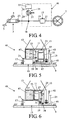
- Figs. 4 and 5 represent a second embodiment of the transmission unit according to the invention, again as component parts of a bicycle. All component parts that are equal to those of the first embodiment described hereinbefore are indicated by like reference numerals.
- the planetary gear set 26 is not installed between the transmission 15 and the wheel hub 11, but between the electromotor 33 and the node 38.
- the third rotational member 31 of the planetary gear set is then constituted by the sun gear and connected to the rotor 37 of the electromotor 33, the first rotational member 27 constituted by the ring gear is connected to a frame 43 of the bicycle and to the stator 35 of the electromotor 33 and the second rotational member 27 constituted by the planet carrier is connected to the input shaft 19 of the transmission 15.
- On the planet carrier are arranged three planet gears which engage the sun gear and the ring gear.
- the input shaft 19 of the transmission 15 is connected to the driving gear 23 of the belt or chain transmission 3 via the node 38.
- the output shaft 21 of the transmission 15 in its turn is connected to the wheel hub 11.
- Fig. 5 furthermore depicts a switching element 45 for changing the transmission ratio of the transmission 15.
- the switching element protrudes from between the shaft and the input of the transmission to beyond the wheel hub.
- the transmission 15 may be arranged as a manually or automatically operated transmission.
- the electronic control unit 47 for controlling/driving the electromotor 33 in the transmission unit shown in Figs. 4 and 5 is accommodated in the wheel hub 11 so that a compact unit is obtained.
- the electromotor 33 as well as the transmission 15 and the planetary gear set 25 in this transmission unit 41 are all concentric to the wheel hub 11 (see Fig. 5 ).
- Fig. 6 gives a diagrammatic representation of a variant of the embodiment represented in Fig. 5 . All component parts that are equal to those of the second embodiment described hereinbefore are indicated by like reference numerals.
- the planetary gear set 25 is accommodated here on the other side of the electromotor 33.
- the transmission 15 may also comprise two parallel driving lines of which at least one transmits the driving torque.
Landscapes
- Engineering & Computer Science (AREA)
- Chemical & Material Sciences (AREA)
- Combustion & Propulsion (AREA)
- Transportation (AREA)
- Mechanical Engineering (AREA)
- Structure Of Transmissions (AREA)
- Connection Of Motors, Electrical Generators, Mechanical Devices, And The Like (AREA)
Description
- The invention relates to a transmission unit for a bicycle, comprising:
- a shaft which is connected to a frame of the bicycle when the transmission unit is applied to the bicycle,
- a wheel hub rotatable around the shaft,
- a transmission concentrically arranged in the wheel hub and having at least two different transmission ratios, which transmission is provided with a support member that is connected to the shaft, and also provided with an input and an output which are concentric to the hub, the input being connected to a driving gear,
- an electromotor concentrically arranged in the wheel hub and having a stator and a rotor, the stator being connected to the frame or the shaft of the bicycle when the transmission unit is applied to the bicycle and the rotor being connected to the input, and
- a planetary gear set arranged in the wheel hub and comprising at least three rotational members which are constituted by a sun gear, a ring gear and a planet carrier carrying at least one planet gear.
- The bicycle may be provided with a motor just like a moped, a scooter, a motor-assisted bicycle for motorized assistance or may be arranged without a motor such as a pedalled bicycle. In the latter case the rider forms the drive source to which the input of the transmission can be coupled. The transmission is for example a generally known hub accelerator and the transmission may be a belt transmission or a chain transmission where the driving gear is constituted by a belt gear or sprocket and the other belt gear or sprocket is connected to pedals.
- The shaft may also be constituted by the support member of the transmission. In that case the support member is fixed directly to the frame of the bicycle and not via a shaft, and the stator is fixed to the support member and the wheel hub is bearing supported on the support member.
- The planetary gear set may be stepped, which is to say that each planet gear may comprise at least two concentric gears side by side and interconnected. Furthermore, the stator may be connected via a connecting element to the frame or to the shaft while the shaft is then connected to the frame. The second rotational member may then be connected to the input or output of the transmission.
- A transmission unit of this type is known from
FR-A-2 873 090 - It is an object of the invention to provide a transmission unit of the type defined in the opening paragraph which is more compact than the known transmission unit and where the drive forces are transmitted with the least possible load on the construction of the transmission unit. For this purpose the transmission unit according to the invention is characterised in that, when the transmission unit is applied to the bicycle, from the rotational members a first rotational member is connected to the frame, a second rotational member is connected to the transmission and the third rotational member is connected to the electromotor or the wheel hub, and in that the planetary gear set is concentric to the shaft and in addition to said planet gear comprises at least one further planet gear which is carried by the planet carrier while the rotational members are concentric to one another. This concentric construction provides a symmetric load on the construction and as a result the transmission unit can have a compact construction.
- The wheel hub may be part of a driven wheel or may be connected to a wheel hub of a driven wheel.
- An embodiment of the transmission unit according to the invention is characterised in that the second rotational member is connected to the input of the transmission and the third rotational member is connected to the electromotor.
- In this embodiment the planetary gear set is preferably arranged between the electromotor and the input of the transmission, the first rotational member being constituted by the ring gear.
- Another embodiment of the transmission unit according to the invention is characterised in that the second rotational member is connected to the output of the transmission and the third rotational member is connected to the wheel hub.
- In this embodiment the first rotational member is preferably constituted by the planet carrier of which the planet gears form at least two pairs of mutually engaging planet gears, one planet gear of each pair engaging the ring gear and the other planet gear engaging the sun gear.
- A further embodiment of the transmission unit according to the invention is characterised in that the first rotational member of the planetary gear set is connected to a clutch element which protrudes from between the wheel hub and the input of the transmission to beyond the wheel hub and, when the transmission unit is applied to the bicycle, is connected to the frame of the bicycle. The clutch element may then be directly connected to the frame or be connected to the shaft while the shaft is connected to the frame.
- The electromotor is preferably a radial flux motor. Furthermore, preferably the input of the transmission seen in axial direction is exclusively arranged on one side of the transmission.
- A further embodiment of the transmission unit according to the invention is characterised in that the transmission unit comprises a torque sensor for sensing the torque on the driving gear, as well as a control unit coupled to the torque sensor and the electromotor, which sensor, if it does not sense any torque, does not cause the electromotor to apply torque either. The control unit and the torque sensor are then preferavly arranged in the wheel hub.
- A still further embodiment of the transmission unit according to the invention is characterised in that the control unit causes the electromotor to apply counter torque while the transmission is being switched, which counter torque is opposed to the drive torque applied by the driving gear during operation. As a result there is no load on the transmission during the switching operation.
- Yet another embodiment of the transmission unit according to the invention is characterised in that the transmission is an automatic transmission which switches between the transmission ratios in dependence on the rpm and/or the driving torque on the input.
- Yet again another embodiment of the transmission unit according to the invention is characterised in that the transmission comprises two parallel driving lines at least one of which always transmitting the driving torque.
- A further embodiment of the transmission unit according to the invention is characterised in that the the transmission comprises a switching element that protrudes to beyond the wheel hub from between the shaft and the input.
- The invention will be described below in more detail based on an example of embodiment of the transmission unit according to the invention represented in the drawing figures, in which:
-
Fig. 1 shows a lay-out of a first embodiment of the transmission unit according to the invention; -
Fig. 2 gives a diagrammatic representation of the transmission unit shown inFig. 1 ; -
Fig. 3 gives a diagrammatic representation of a variant of the embodiment represented inFig. 2 ; -
Fig. 4 shows a lay-out of a second embodiment of the transmission unit according to the invention; -
Fig. 5 gives a diagrammatic representation of the transmission unit shown inFig. 4 ; and -
Fig. 6 gives a diagrammatic representation of a variant of the embodiment represented inFig. 5 . -
Figs. 1 and 2 show a first embodiment of the transmission unit according to the invention as forming part of a bicycle. Thetransmission unit 1 is arranged between a belt orchain transmission 3 which is connected topedals 5 and awheel 7 of the bicycle. Thetransmission unit 1 comprises ashaft 9 which is connected to a frame of the bicycle, as well as awheel hub 11 rotatable around the shaft and in whichspokes 13 of the wheel are mounted. - The
transmission unit 1 further comprises atransmission 15 having at least two different transmission ratios. The transmission has a support member 17 (for example the transmission housing) which is connected to the shaft 9 (seeFig. 2 ) as well as aninput 19 and anoutput 21 which are concentric to thewheel hub 11. Theinput 19 is in this case constituted by a shaft to which adriving gear 23 is mounted and theoutput 21 is coupled to thewheel hub 11 via aplanetary gear set 25. The planetary gear set comprises a firstrotational member 27 which is formed in this embodiment by a planet carrier and which is fixedly connected to theshaft 9, as well as a secondrotational member 29 constituted by a sun gear which is connected to theoutput 21 of the transmission, and a thirdrotational member 31 constituted by a ring gear which is connected to thewheel hub 11. On the planet carrier there are three pairs of interengaging planet gears one of which engaging the sun gear and the other the ring gear. - The
transmission unit 1 further includes anelectromotor 33 having astator 35 which is connected to theshaft 9 and to the firstrotational member 27, and arotor 37 which is connected to theinput 19 of the transmission via anode 38. Thestator 35 and therotor 37 of theelectromotor 33 are concentric to the wheel hub 11 (seeFig. 2 ). - During the switching of the
transmission 15 from one to the other transmission theelectromotor 33 can produce a counter torque that is opposed to the drive torque applied by the drive source (cyclist) by means of thepedals 5. Thetransmission 15 may be an automatic transmission which switches between the transmission ratios in dependence on the rpm and/or the drive torque on theinput 19. -
Fig. 3 gives a diagrammatic representation of a variant of the embodiment represented inFig. 2 . All component parts that are equal to those of the first embodiment described hereinbefore are indicated by like reference numerals. In contrast to the first embodiment, in thistransmission unit 39 the planet carrier constituting the thirdrotational member 31 in this embodiment comprises several planets and is connected to thewheel hub 11 and the firstrotational member 27 which is now constituted by the ring gear is connected to theshaft 9. -
Figs. 4 and 5 represent a second embodiment of the transmission unit according to the invention, again as component parts of a bicycle. All component parts that are equal to those of the first embodiment described hereinbefore are indicated by like reference numerals. - In this
transmission unit 41 the planetary gear set 26 is not installed between thetransmission 15 and thewheel hub 11, but between the electromotor 33 and thenode 38. The thirdrotational member 31 of the planetary gear set is then constituted by the sun gear and connected to therotor 37 of theelectromotor 33, the firstrotational member 27 constituted by the ring gear is connected to aframe 43 of the bicycle and to thestator 35 of theelectromotor 33 and the secondrotational member 27 constituted by the planet carrier is connected to theinput shaft 19 of thetransmission 15. On the planet carrier are arranged three planet gears which engage the sun gear and the ring gear. - The
input shaft 19 of thetransmission 15 is connected to thedriving gear 23 of the belt orchain transmission 3 via thenode 38. Theoutput shaft 21 of thetransmission 15 in its turn is connected to thewheel hub 11. -
Fig. 5 furthermore depicts a switchingelement 45 for changing the transmission ratio of thetransmission 15. The switching element protrudes from between the shaft and the input of the transmission to beyond the wheel hub. In thistransmission unit 41 thetransmission 15 may be arranged as a manually or automatically operated transmission. Theelectronic control unit 47 for controlling/driving theelectromotor 33 in the transmission unit shown inFigs. 4 and 5 is accommodated in thewheel hub 11 so that a compact unit is obtained. - The
electromotor 33 as well as thetransmission 15 and the planetary gear set 25 in thistransmission unit 41 are all concentric to the wheel hub 11 (seeFig. 5 ). -
Fig. 6 gives a diagrammatic representation of a variant of the embodiment represented inFig. 5 . All component parts that are equal to those of the second embodiment described hereinbefore are indicated by like reference numerals. The planetary gear set 25 is accommodated here on the other side of theelectromotor 33. - Albeit the invention has been described in the foregoing based on the drawings, it should be observed that the invention is not by any manner or means restricted to the embodiment shown in the drawings. The invention also extends to all embodiments deviating from the embodiment shown in the drawings within the scope defined by the claims. For example, the
transmission 15 may also comprise two parallel driving lines of which at least one transmits the driving torque.
Claims (15)
- A transmission unit (1) for a bicycle, comprising:- a shaft (9) which is connected to a frame of the bicycle when the transmission unit is
applied to the bicycle,- a wheel hub (11) rotatable around the shaft (9),- a transmission (15) concentrically arranged in the wheel hub (11) and having at least two different transmission ratios, which transmission (15) is provided with a support member (17) that is connected to the shaft (9), and also provided with an input (19) and an output (20) which are concentric to the hub (11), the input (19) being connected to a driving gear- an electromotor (33) concentrically arranged in the wheel hub (11) and having a stator (35) and a rotor (37), the stator (35) being connected to the frame or the shaft (9) of the bicycle when the transmission unit is applied to the bicycle and the rotor (27) being connected to the input (19),
and- a planetary gear set (25) arranged in the wheel hub (11) and comprising at least three rotational members which are constituted by a sun gear, a ring gear and a planet carrier carrying at least one planet gear,
characterised in that, when the transmission unit (1) is applied to the bicycle, from the rotational members a first rotational member (27) is connected to the frame, a second rotational member (29) is connected to the transmission (15), and the third rotational member (31) is connected to the electromotor (33) or the wheel hub (11), and in that the planetary gear set is concentric to the shaft (9) and in addition to said planet gear comprises at least one further planet gear which is carried by the planet carrier while the rotational members are concentric to one another. - A transmission unit as claimed in claim 1, characterised in that the second rotational member (29) is connected to the input of the transmission (15) and the third rotational member (31) is connected to the electromotor (33).
- A transmission unit as claimed in claim 2, characterised in that the planetary gear set (25) is arranged between the electromotor (33) and the input of the transmission (15), the first rotational member (27) being constituted by the ring gear.
- A transmission unit as claimed in claim 1, characterised in that the second rotational member (29) is connected to the input of the transmission (15) and the third rotational member (31) is connected to the wheel hub.
- A transmission unit as claimed in claim 4, characterised in that the first rotational member (27) is constituted by the planet carrier of which the planet gears form at least two pairs of mutually engaging planet gears, one planet gear of each pair engaging the ring gear and the other planet gear engaging the sun gear.
- A transmission unit as claimed in claim 2, 3, 4 or 5, characterised in that the first rotational member (27) of the planetary gear set (25) is connected to a clutch element (45) which protrudes from between the wheel hub (11) and the input of the transmission to beyond the wheel hub (11) and, when the transmission unit is applied to the bicycle, is connected to the frame of the bicycle.
- A transmission unit as claimed in any one of the preceding claims, characterised in that the electromotor (33) is a radial flux motor.
- A transmission unit as claimed in any one of the preceding claims, characterised in that the input of the transmission seen in axial direction is exclusively arranged on one side of the transmission (15).
- A transmison unit as claimed in any one of the preceding claims, characterised in that the transmission unit comprises a torque sensor for sensing the torque on the driving gear, as well as a control unit coupled to the torque sensor and the electromotor (33), which sensor, if it does not sense any torque, does not cause the electromotor to apply torque either.
- A transmission unit as claimed in claim 9, characterised in that the control unit is arranged in the wheel hub (11).
- A transmission unit as claimed in claim 9 or 10, characterised in that the torque sensor is arranged in the wheel hub (11).
- A transmission unit as claimed in claim 9, 10 or 11, characterised in that the control unit causes the electromotor (33) to apply counter torque while the transmission (15) is being switched, which counter torque is opposed to the drive torque applied by the driving gear during operation.
- A transmission unit as claimed in any one of the preceding claims, characterised in that the transmission (15) is an automatic transmission which switches between the transmission ratios in dependence on the rpm and/or the driving torque on the input.
- A transmission unit as claimed in any one of the preceding claims, characterised in that the transmission (15) comprises two parallel driving lines at least one of which always transmitting the drive torque.
- A transmission unit as claimed in any one of the preceding claims, characterised in that the transmission (15) comprises a switching element (45) that protrudes to beyond the wheel hub from between the shaft and the input.
Applications Claiming Priority (2)
| Application Number | Priority Date | Filing Date | Title |
|---|---|---|---|
| NL2002305A NL2002305C2 (en) | 2008-12-08 | 2008-12-08 | TRANSMISSION UNIT FOR A WHEEL WHEEL. |
| PCT/NL2009/050751 WO2010068101A1 (en) | 2008-12-08 | 2009-12-08 | Transmission unit for a bicycle |
Publications (2)
| Publication Number | Publication Date |
|---|---|
| EP2373538A1 EP2373538A1 (en) | 2011-10-12 |
| EP2373538B1 true EP2373538B1 (en) | 2013-10-23 |
Family
ID=40609959
Family Applications (1)
| Application Number | Title | Priority Date | Filing Date |
|---|---|---|---|
| EP09768451.8A Active EP2373538B1 (en) | 2008-12-08 | 2009-12-08 | Transmission unit for a bicycle |
Country Status (4)
| Country | Link |
|---|---|
| EP (1) | EP2373538B1 (en) |
| ES (1) | ES2443048T3 (en) |
| NL (1) | NL2002305C2 (en) |
| WO (1) | WO2010068101A1 (en) |
Families Citing this family (5)
| Publication number | Priority date | Publication date | Assignee | Title |
|---|---|---|---|---|
| ITMO20110061A1 (en) | 2011-03-16 | 2012-09-17 | C R D Ct Ricerche Ducati Trent O S R L | WHEEL FOR ASSISTED RIDING BICYCLES |
| US11014627B2 (en) | 2016-05-04 | 2021-05-25 | Farthing Technology Pty Ltd | Pedal cycle drivetrain and a human powered vehicle |
| DE102019117847A1 (en) * | 2018-12-17 | 2020-06-18 | Schaeffler Technologies AG & Co. KG | Wheel hub motor with hollow axle |
| DE102019218617B4 (en) * | 2019-11-29 | 2022-10-27 | Zf Friedrichshafen Ag | Gear arrangement for a bicycle and a bicycle |
| NL2026760B1 (en) * | 2020-10-23 | 2022-06-17 | Advatech B V | Hybrid drive system for a bicycle |
Family Cites Families (5)
| Publication number | Priority date | Publication date | Assignee | Title |
|---|---|---|---|---|
| EP0832816A1 (en) * | 1996-09-26 | 1998-04-01 | Mitsubishi Heavy Industries, Ltd. | Driving unit for electric motor driven bicycle |
| US6354980B1 (en) * | 1997-11-10 | 2002-03-12 | Frederic Francis Grant | Automatic transmission systems for humanly powered vehicles |
| JP3939862B2 (en) * | 1998-08-18 | 2007-07-04 | ヤマハ発動機株式会社 | Motor drive unit for electric bicycle |
| EP1298051A3 (en) * | 2001-09-28 | 2005-12-14 | Kabushiki Kaisha Moric | Electrically assisted unit |
| FR2873090A1 (en) * | 2004-07-16 | 2006-01-20 | Inivi T Sarl | Wheel hub for bicycle, has pedaling assistance device with motor connected to body flange and reducer having splined crown gear which has flange in which recess is arranged to form cylindrical housing for receiving speed shifting unit |
-
2008
- 2008-12-08 NL NL2002305A patent/NL2002305C2/en not_active IP Right Cessation
-
2009
- 2009-12-08 WO PCT/NL2009/050751 patent/WO2010068101A1/en active Application Filing
- 2009-12-08 ES ES09768451.8T patent/ES2443048T3/en active Active
- 2009-12-08 EP EP09768451.8A patent/EP2373538B1/en active Active
Also Published As
| Publication number | Publication date |
|---|---|
| ES2443048T3 (en) | 2014-02-17 |
| NL2002305C2 (en) | 2010-06-09 |
| WO2010068101A1 (en) | 2010-06-17 |
| EP2373538A1 (en) | 2011-10-12 |
Similar Documents
| Publication | Publication Date | Title |
|---|---|---|
| JP5373946B1 (en) | Bicycle drive unit | |
| TWI822784B (en) | Pedaling bearing transmission in form of planet transmission for a bicycle or pedelec | |
| US10343746B2 (en) | Drive assembly for a manually driven vehicle with an electric auxiliary drive, method for regulating a drive assembly of this type, and use | |
| US20190351972A1 (en) | Transmission for a Bicycle | |
| EP3034387B1 (en) | Hub motor structure | |
| US10919599B2 (en) | Bicycle having electric drive or auxiliary drive | |
| EP2373538B1 (en) | Transmission unit for a bicycle | |
| KR101172307B1 (en) | Hub motor unit for electric bicycle | |
| JP2007050877A (en) | Power system for hybrid vehicle | |
| US11046391B2 (en) | Transmission for a bicycle | |
| TWI807098B (en) | Drive device for a bicycle or pedelec | |
| WO2016143303A1 (en) | Electric bicycle | |
| WO2018226095A1 (en) | Transmission for a bicycle | |
| WO2020260773A1 (en) | Power unit and method | |
| CN103723234B (en) | The driver element of bicycle | |
| TWM494744U (en) | Assembly for bicycle | |
| TW201341262A (en) | Bicycle drive unit | |
| CN107804162A (en) | Variable speed drive system | |
| JP2001234990A (en) | Transmission | |
| CN112303197A (en) | Transmission device for human-powered vehicle and auxiliary system for human-powered vehicle provided with same | |
| JP2014113912A (en) | Drive unit for bicycle | |
| WO2018224921A1 (en) | A vehicle | |
| JP2017141929A (en) | Transmission device | |
| WO2024029381A1 (en) | Electric power assist unit for bicycle, and electric power assisted bicycle | |
| JPH05310174A (en) | Driving gear of motorcycle |
Legal Events
| Date | Code | Title | Description |
|---|---|---|---|
| PUAI | Public reference made under article 153(3) epc to a published international application that has entered the european phase |
Free format text: ORIGINAL CODE: 0009012 |
|
| 17P | Request for examination filed |
Effective date: 20110708 |
|
| AK | Designated contracting states |
Kind code of ref document: A1 Designated state(s): AT BE BG CH CY CZ DE DK EE ES FI FR GB GR HR HU IE IS IT LI LT LU LV MC MK MT NL NO PL PT RO SE SI SK SM TR |
|
| RIN1 | Information on inventor provided before grant (corrected) |
Inventor name: BASTIANEN, JOHANNES PETRUS CATHARINA MICHAEL Inventor name: VROEMEN, BAS GERARD Inventor name: VAN DRUTEN, ROELL MARIE Inventor name: JANSSEN, BART RICHARD ALEXANDER |
|
| DAX | Request for extension of the european patent (deleted) | ||
| GRAP | Despatch of communication of intention to grant a patent |
Free format text: ORIGINAL CODE: EPIDOSNIGR1 |
|
| INTG | Intention to grant announced |
Effective date: 20130516 |
|
| GRAS | Grant fee paid |
Free format text: ORIGINAL CODE: EPIDOSNIGR3 |
|
| GRAA | (expected) grant |
Free format text: ORIGINAL CODE: 0009210 |
|
| STAA | Information on the status of an ep patent application or granted ep patent |
Free format text: STATUS: THE PATENT HAS BEEN GRANTED |
|
| AK | Designated contracting states |
Kind code of ref document: B1 Designated state(s): AT BE BG CH CY CZ DE DK EE ES FI FR GB GR HR HU IE IS IT LI LT LU LV MC MK MT NL NO PL PT RO SE SI SK SM TR |
|
| REG | Reference to a national code |
Ref country code: GB Ref legal event code: FG4D |
|
| REG | Reference to a national code |
Ref country code: CH Ref legal event code: EP |
|
| REG | Reference to a national code |
Ref country code: AT Ref legal event code: REF Ref document number: 637412 Country of ref document: AT Kind code of ref document: T Effective date: 20131115 |
|
| REG | Reference to a national code |
Ref country code: IE Ref legal event code: FG4D |
|
| REG | Reference to a national code |
Ref country code: DE Ref legal event code: R096 Ref document number: 602009019648 Country of ref document: DE Effective date: 20131219 |
|
| PGFP | Annual fee paid to national office [announced via postgrant information from national office to epo] |
Ref country code: GB Payment date: 20131230 Year of fee payment: 5 |
|
| REG | Reference to a national code |
Ref country code: ES Ref legal event code: FG2A Ref document number: 2443048 Country of ref document: ES Kind code of ref document: T3 Effective date: 20140217 |
|
| PGFP | Annual fee paid to national office [announced via postgrant information from national office to epo] |
Ref country code: NL Payment date: 20131231 Year of fee payment: 5 |
|
| REG | Reference to a national code |
Ref country code: NL Ref legal event code: VDEP Effective date: 20131023 |
|
| REG | Reference to a national code |
Ref country code: AT Ref legal event code: MK05 Ref document number: 637412 Country of ref document: AT Kind code of ref document: T Effective date: 20131023 |
|
| REG | Reference to a national code |
Ref country code: LT Ref legal event code: MG4D |
|
| PGFP | Annual fee paid to national office [announced via postgrant information from national office to epo] |
Ref country code: BE Payment date: 20131230 Year of fee payment: 5 |
|
| PG25 | Lapsed in a contracting state [announced via postgrant information from national office to epo] |
Ref country code: SE Free format text: LAPSE BECAUSE OF FAILURE TO SUBMIT A TRANSLATION OF THE DESCRIPTION OR TO PAY THE FEE WITHIN THE PRESCRIBED TIME-LIMIT Effective date: 20131023 Ref country code: HR Free format text: LAPSE BECAUSE OF FAILURE TO SUBMIT A TRANSLATION OF THE DESCRIPTION OR TO PAY THE FEE WITHIN THE PRESCRIBED TIME-LIMIT Effective date: 20131023 Ref country code: FI Free format text: LAPSE BECAUSE OF FAILURE TO SUBMIT A TRANSLATION OF THE DESCRIPTION OR TO PAY THE FEE WITHIN THE PRESCRIBED TIME-LIMIT Effective date: 20131023 Ref country code: IS Free format text: LAPSE BECAUSE OF FAILURE TO SUBMIT A TRANSLATION OF THE DESCRIPTION OR TO PAY THE FEE WITHIN THE PRESCRIBED TIME-LIMIT Effective date: 20140223 Ref country code: NO Free format text: LAPSE BECAUSE OF FAILURE TO SUBMIT A TRANSLATION OF THE DESCRIPTION OR TO PAY THE FEE WITHIN THE PRESCRIBED TIME-LIMIT Effective date: 20140123 Ref country code: LT Free format text: LAPSE BECAUSE OF FAILURE TO SUBMIT A TRANSLATION OF THE DESCRIPTION OR TO PAY THE FEE WITHIN THE PRESCRIBED TIME-LIMIT Effective date: 20131023 Ref country code: NL Free format text: LAPSE BECAUSE OF FAILURE TO SUBMIT A TRANSLATION OF THE DESCRIPTION OR TO PAY THE FEE WITHIN THE PRESCRIBED TIME-LIMIT Effective date: 20131023 |
|
| PG25 | Lapsed in a contracting state [announced via postgrant information from national office to epo] |
Ref country code: CY Free format text: LAPSE BECAUSE OF FAILURE TO SUBMIT A TRANSLATION OF THE DESCRIPTION OR TO PAY THE FEE WITHIN THE PRESCRIBED TIME-LIMIT Effective date: 20131023 Ref country code: AT Free format text: LAPSE BECAUSE OF FAILURE TO SUBMIT A TRANSLATION OF THE DESCRIPTION OR TO PAY THE FEE WITHIN THE PRESCRIBED TIME-LIMIT Effective date: 20131023 Ref country code: LV Free format text: LAPSE BECAUSE OF FAILURE TO SUBMIT A TRANSLATION OF THE DESCRIPTION OR TO PAY THE FEE WITHIN THE PRESCRIBED TIME-LIMIT Effective date: 20131023 |
|
| PGFP | Annual fee paid to national office [announced via postgrant information from national office to epo] |
Ref country code: ES Payment date: 20140129 Year of fee payment: 5 |
|
| PG25 | Lapsed in a contracting state [announced via postgrant information from national office to epo] |
Ref country code: PT Free format text: LAPSE BECAUSE OF FAILURE TO SUBMIT A TRANSLATION OF THE DESCRIPTION OR TO PAY THE FEE WITHIN THE PRESCRIBED TIME-LIMIT Effective date: 20140224 |
|
| REG | Reference to a national code |
Ref country code: DE Ref legal event code: R097 Ref document number: 602009019648 Country of ref document: DE |
|
| PG25 | Lapsed in a contracting state [announced via postgrant information from national office to epo] |
Ref country code: EE Free format text: LAPSE BECAUSE OF FAILURE TO SUBMIT A TRANSLATION OF THE DESCRIPTION OR TO PAY THE FEE WITHIN THE PRESCRIBED TIME-LIMIT Effective date: 20131023 |
|
| REG | Reference to a national code |
Ref country code: CH Ref legal event code: PL |
|
| PG25 | Lapsed in a contracting state [announced via postgrant information from national office to epo] |
Ref country code: PL Free format text: LAPSE BECAUSE OF FAILURE TO SUBMIT A TRANSLATION OF THE DESCRIPTION OR TO PAY THE FEE WITHIN THE PRESCRIBED TIME-LIMIT Effective date: 20131023 Ref country code: CZ Free format text: LAPSE BECAUSE OF FAILURE TO SUBMIT A TRANSLATION OF THE DESCRIPTION OR TO PAY THE FEE WITHIN THE PRESCRIBED TIME-LIMIT Effective date: 20131023 Ref country code: RO Free format text: LAPSE BECAUSE OF FAILURE TO SUBMIT A TRANSLATION OF THE DESCRIPTION OR TO PAY THE FEE WITHIN THE PRESCRIBED TIME-LIMIT Effective date: 20131023 Ref country code: LU Free format text: LAPSE BECAUSE OF FAILURE TO SUBMIT A TRANSLATION OF THE DESCRIPTION OR TO PAY THE FEE WITHIN THE PRESCRIBED TIME-LIMIT Effective date: 20131208 Ref country code: SK Free format text: LAPSE BECAUSE OF FAILURE TO SUBMIT A TRANSLATION OF THE DESCRIPTION OR TO PAY THE FEE WITHIN THE PRESCRIBED TIME-LIMIT Effective date: 20131023 |
|
| PLBE | No opposition filed within time limit |
Free format text: ORIGINAL CODE: 0009261 |
|
| STAA | Information on the status of an ep patent application or granted ep patent |
Free format text: STATUS: NO OPPOSITION FILED WITHIN TIME LIMIT |
|
| REG | Reference to a national code |
Ref country code: IE Ref legal event code: MM4A |
|
| PG25 | Lapsed in a contracting state [announced via postgrant information from national office to epo] |
Ref country code: DK Free format text: LAPSE BECAUSE OF FAILURE TO SUBMIT A TRANSLATION OF THE DESCRIPTION OR TO PAY THE FEE WITHIN THE PRESCRIBED TIME-LIMIT Effective date: 20131023 |
|
| 26N | No opposition filed |
Effective date: 20140724 |
|
| PG25 | Lapsed in a contracting state [announced via postgrant information from national office to epo] |
Ref country code: IE Free format text: LAPSE BECAUSE OF NON-PAYMENT OF DUE FEES Effective date: 20131208 Ref country code: LI Free format text: LAPSE BECAUSE OF NON-PAYMENT OF DUE FEES Effective date: 20131231 Ref country code: CH Free format text: LAPSE BECAUSE OF NON-PAYMENT OF DUE FEES Effective date: 20131231 |
|
| REG | Reference to a national code |
Ref country code: DE Ref legal event code: R097 Ref document number: 602009019648 Country of ref document: DE Effective date: 20140724 |
|
| REG | Reference to a national code |
Ref country code: NL Ref legal event code: RD1H Effective date: 20150108 |
|
| PG25 | Lapsed in a contracting state [announced via postgrant information from national office to epo] |
Ref country code: SI Free format text: LAPSE BECAUSE OF FAILURE TO SUBMIT A TRANSLATION OF THE DESCRIPTION OR TO PAY THE FEE WITHIN THE PRESCRIBED TIME-LIMIT Effective date: 20131023 |
|
| PG25 | Lapsed in a contracting state [announced via postgrant information from national office to epo] |
Ref country code: MC Free format text: LAPSE BECAUSE OF FAILURE TO SUBMIT A TRANSLATION OF THE DESCRIPTION OR TO PAY THE FEE WITHIN THE PRESCRIBED TIME-LIMIT Effective date: 20131023 |
|
| PG25 | Lapsed in a contracting state [announced via postgrant information from national office to epo] |
Ref country code: SM Free format text: LAPSE BECAUSE OF FAILURE TO SUBMIT A TRANSLATION OF THE DESCRIPTION OR TO PAY THE FEE WITHIN THE PRESCRIBED TIME-LIMIT Effective date: 20131023 |
|
| PG25 | Lapsed in a contracting state [announced via postgrant information from national office to epo] |
Ref country code: TR Free format text: LAPSE BECAUSE OF FAILURE TO SUBMIT A TRANSLATION OF THE DESCRIPTION OR TO PAY THE FEE WITHIN THE PRESCRIBED TIME-LIMIT Effective date: 20131023 Ref country code: BE Free format text: LAPSE BECAUSE OF NON-PAYMENT OF DUE FEES Effective date: 20141231 |
|
| PG25 | Lapsed in a contracting state [announced via postgrant information from national office to epo] |
Ref country code: BG Free format text: LAPSE BECAUSE OF FAILURE TO SUBMIT A TRANSLATION OF THE DESCRIPTION OR TO PAY THE FEE WITHIN THE PRESCRIBED TIME-LIMIT Effective date: 20131023 Ref country code: MK Free format text: LAPSE BECAUSE OF FAILURE TO SUBMIT A TRANSLATION OF THE DESCRIPTION OR TO PAY THE FEE WITHIN THE PRESCRIBED TIME-LIMIT Effective date: 20131023 Ref country code: HU Free format text: LAPSE BECAUSE OF FAILURE TO SUBMIT A TRANSLATION OF THE DESCRIPTION OR TO PAY THE FEE WITHIN THE PRESCRIBED TIME-LIMIT; INVALID AB INITIO Effective date: 20091208 |
|
| GBPC | Gb: european patent ceased through non-payment of renewal fee |
Effective date: 20141208 |
|
| PG25 | Lapsed in a contracting state [announced via postgrant information from national office to epo] |
Ref country code: GR Free format text: LAPSE BECAUSE OF NON-PAYMENT OF DUE FEES Effective date: 20131023 Ref country code: MT Free format text: LAPSE BECAUSE OF FAILURE TO SUBMIT A TRANSLATION OF THE DESCRIPTION OR TO PAY THE FEE WITHIN THE PRESCRIBED TIME-LIMIT Effective date: 20131023 |
|
| PG25 | Lapsed in a contracting state [announced via postgrant information from national office to epo] |
Ref country code: GB Free format text: LAPSE BECAUSE OF NON-PAYMENT OF DUE FEES Effective date: 20141208 |
|
| REG | Reference to a national code |
Ref country code: FR Ref legal event code: PLFP Year of fee payment: 7 |
|
| REG | Reference to a national code |
Ref country code: ES Ref legal event code: FD2A Effective date: 20160127 |
|
| PG25 | Lapsed in a contracting state [announced via postgrant information from national office to epo] |
Ref country code: ES Free format text: LAPSE BECAUSE OF NON-PAYMENT OF DUE FEES Effective date: 20141209 |
|
| PG25 | Lapsed in a contracting state [announced via postgrant information from national office to epo] |
Ref country code: GR Free format text: LAPSE BECAUSE OF FAILURE TO SUBMIT A TRANSLATION OF THE DESCRIPTION OR TO PAY THE FEE WITHIN THE PRESCRIBED TIME-LIMIT Effective date: 20140124 |
|
| REG | Reference to a national code |
Ref country code: FR Ref legal event code: PLFP Year of fee payment: 8 |
|
| REG | Reference to a national code |
Ref country code: FR Ref legal event code: PLFP Year of fee payment: 9 |
|
| P01 | Opt-out of the competence of the unified patent court (upc) registered |
Effective date: 20230519 |
|
| PGFP | Annual fee paid to national office [announced via postgrant information from national office to epo] |
Ref country code: IT Payment date: 20231228 Year of fee payment: 15 Ref country code: FR Payment date: 20231221 Year of fee payment: 15 Ref country code: DE Payment date: 20231214 Year of fee payment: 15 |