EP2364112B1 - Apparatus and methods for sealing a vascular puncture - Google Patents
Apparatus and methods for sealing a vascular puncture Download PDFInfo
- Publication number
- EP2364112B1 EP2364112B1 EP09752685.9A EP09752685A EP2364112B1 EP 2364112 B1 EP2364112 B1 EP 2364112B1 EP 09752685 A EP09752685 A EP 09752685A EP 2364112 B1 EP2364112 B1 EP 2364112B1
- Authority
- EP
- European Patent Office
- Prior art keywords
- cartridge
- sealant
- pusher member
- hub
- spring
- Prior art date
- Legal status (The legal status is an assumption and is not a legal conclusion. Google has not performed a legal analysis and makes no representation as to the accuracy of the status listed.)
- Active
Links
- 238000007789 sealing Methods 0.000 title claims description 25
- 238000000034 method Methods 0.000 title description 30
- 230000002792 vascular Effects 0.000 title description 3
- 239000000565 sealant Substances 0.000 claims description 127
- 238000003780 insertion Methods 0.000 claims description 7
- 230000037431 insertion Effects 0.000 claims description 7
- 239000003550 marker Substances 0.000 claims description 7
- 238000005381 potential energy Methods 0.000 claims description 4
- 239000000463 material Substances 0.000 description 15
- 210000004204 blood vessel Anatomy 0.000 description 10
- 230000007704 transition Effects 0.000 description 10
- 230000023597 hemostasis Effects 0.000 description 8
- 238000006073 displacement reaction Methods 0.000 description 7
- 239000012530 fluid Substances 0.000 description 7
- 239000008280 blood Substances 0.000 description 6
- 210000004369 blood Anatomy 0.000 description 6
- 230000008878 coupling Effects 0.000 description 5
- 238000010168 coupling process Methods 0.000 description 5
- 238000005859 coupling reaction Methods 0.000 description 5
- 239000000017 hydrogel Substances 0.000 description 5
- 230000007246 mechanism Effects 0.000 description 5
- 230000000007 visual effect Effects 0.000 description 5
- 230000009471 action Effects 0.000 description 4
- 230000001464 adherent effect Effects 0.000 description 3
- 210000001124 body fluid Anatomy 0.000 description 3
- 238000000576 coating method Methods 0.000 description 3
- 150000001875 compounds Chemical class 0.000 description 3
- 230000006835 compression Effects 0.000 description 3
- 238000007906 compression Methods 0.000 description 3
- 229920001223 polyethylene glycol Polymers 0.000 description 3
- 229920000954 Polyglycolide Polymers 0.000 description 2
- 239000000853 adhesive Substances 0.000 description 2
- 230000001070 adhesive effect Effects 0.000 description 2
- 239000011248 coating agent Substances 0.000 description 2
- 208000014674 injury Diseases 0.000 description 2
- 229920003023 plastic Polymers 0.000 description 2
- 239000004033 plastic Substances 0.000 description 2
- 229920000642 polymer Polymers 0.000 description 2
- 230000003331 prothrombotic effect Effects 0.000 description 2
- 239000011343 solid material Substances 0.000 description 2
- 229920002994 synthetic fiber Polymers 0.000 description 2
- 230000001225 therapeutic effect Effects 0.000 description 2
- 210000005166 vasculature Anatomy 0.000 description 2
- 229920002134 Carboxymethyl cellulose Polymers 0.000 description 1
- 102000008186 Collagen Human genes 0.000 description 1
- 108010035532 Collagen Proteins 0.000 description 1
- 102000009123 Fibrin Human genes 0.000 description 1
- 108010073385 Fibrin Proteins 0.000 description 1
- BWGVNKXGVNDBDI-UHFFFAOYSA-N Fibrin monomer Chemical compound CNC(=O)CNC(=O)CN BWGVNKXGVNDBDI-UHFFFAOYSA-N 0.000 description 1
- 108010010803 Gelatin Proteins 0.000 description 1
- 206010018852 Haematoma Diseases 0.000 description 1
- 208000032843 Hemorrhage Diseases 0.000 description 1
- 229920002201 Oxidized cellulose Polymers 0.000 description 1
- 239000002202 Polyethylene glycol Substances 0.000 description 1
- 239000004372 Polyvinyl alcohol Substances 0.000 description 1
- FAPWRFPIFSIZLT-UHFFFAOYSA-M Sodium chloride Chemical compound [Na+].[Cl-] FAPWRFPIFSIZLT-UHFFFAOYSA-M 0.000 description 1
- 208000027418 Wounds and injury Diseases 0.000 description 1
- 230000003213 activating effect Effects 0.000 description 1
- 230000004913 activation Effects 0.000 description 1
- 230000002411 adverse Effects 0.000 description 1
- 229920000615 alginic acid Polymers 0.000 description 1
- 235000010443 alginic acid Nutrition 0.000 description 1
- 230000000712 assembly Effects 0.000 description 1
- 238000000429 assembly Methods 0.000 description 1
- 230000000740 bleeding effect Effects 0.000 description 1
- 239000010839 body fluid Substances 0.000 description 1
- 239000001768 carboxy methyl cellulose Substances 0.000 description 1
- 235000010948 carboxy methyl cellulose Nutrition 0.000 description 1
- 239000008112 carboxymethyl-cellulose Substances 0.000 description 1
- 229940105329 carboxymethylcellulose Drugs 0.000 description 1
- 210000001715 carotid artery Anatomy 0.000 description 1
- 125000003636 chemical group Chemical group 0.000 description 1
- 239000003795 chemical substances by application Substances 0.000 description 1
- 229920001436 collagen Polymers 0.000 description 1
- 229960005188 collagen Drugs 0.000 description 1
- 230000000295 complement effect Effects 0.000 description 1
- 239000002131 composite material Substances 0.000 description 1
- 238000012790 confirmation Methods 0.000 description 1
- 238000010276 construction Methods 0.000 description 1
- 230000006378 damage Effects 0.000 description 1
- 239000003814 drug Substances 0.000 description 1
- -1 e.g. Substances 0.000 description 1
- 238000005530 etching Methods 0.000 description 1
- 210000001105 femoral artery Anatomy 0.000 description 1
- 229950003499 fibrin Drugs 0.000 description 1
- 230000009969 flowable effect Effects 0.000 description 1
- 229920000159 gelatin Polymers 0.000 description 1
- 239000008273 gelatin Substances 0.000 description 1
- 235000019322 gelatine Nutrition 0.000 description 1
- 235000011852 gelatine desserts Nutrition 0.000 description 1
- 230000035876 healing Effects 0.000 description 1
- 230000036571 hydration Effects 0.000 description 1
- 238000006703 hydration reaction Methods 0.000 description 1
- 208000015181 infectious disease Diseases 0.000 description 1
- 238000013152 interventional procedure Methods 0.000 description 1
- 239000007788 liquid Substances 0.000 description 1
- 238000003754 machining Methods 0.000 description 1
- 230000013011 mating Effects 0.000 description 1
- 239000002184 metal Substances 0.000 description 1
- 229910052751 metal Inorganic materials 0.000 description 1
- 150000002739 metals Chemical class 0.000 description 1
- 230000005012 migration Effects 0.000 description 1
- 238000013508 migration Methods 0.000 description 1
- 238000012986 modification Methods 0.000 description 1
- 230000004048 modification Effects 0.000 description 1
- 238000012544 monitoring process Methods 0.000 description 1
- 238000000465 moulding Methods 0.000 description 1
- 229940107304 oxidized cellulose Drugs 0.000 description 1
- 239000008177 pharmaceutical agent Substances 0.000 description 1
- 229920002451 polyvinyl alcohol Polymers 0.000 description 1
- 239000002243 precursor Substances 0.000 description 1
- 230000008569 process Effects 0.000 description 1
- 230000001737 promoting effect Effects 0.000 description 1
- 108090000623 proteins and genes Proteins 0.000 description 1
- 102000004169 proteins and genes Human genes 0.000 description 1
- 238000005096 rolling process Methods 0.000 description 1
- 239000012812 sealant material Substances 0.000 description 1
- 238000004904 shortening Methods 0.000 description 1
- 239000011780 sodium chloride Substances 0.000 description 1
- 239000007787 solid Substances 0.000 description 1
- 230000008961 swelling Effects 0.000 description 1
- 230000008733 trauma Effects 0.000 description 1
- 238000003466 welding Methods 0.000 description 1
Images


Classifications
-
- A—HUMAN NECESSITIES
- A61—MEDICAL OR VETERINARY SCIENCE; HYGIENE
- A61B—DIAGNOSIS; SURGERY; IDENTIFICATION
- A61B17/00—Surgical instruments, devices or methods, e.g. tourniquets
- A61B17/0057—Implements for plugging an opening in the wall of a hollow or tubular organ, e.g. for sealing a vessel puncture or closing a cardiac septal defect
- A61B2017/00646—Type of implements
- A61B2017/0065—Type of implements the implement being an adhesive
-
- A—HUMAN NECESSITIES
- A61—MEDICAL OR VETERINARY SCIENCE; HYGIENE
- A61B—DIAGNOSIS; SURGERY; IDENTIFICATION
- A61B17/00—Surgical instruments, devices or methods, e.g. tourniquets
- A61B17/0057—Implements for plugging an opening in the wall of a hollow or tubular organ, e.g. for sealing a vessel puncture or closing a cardiac septal defect
- A61B2017/00646—Type of implements
- A61B2017/00654—Type of implements entirely comprised between the two sides of the opening
-
- A—HUMAN NECESSITIES
- A61—MEDICAL OR VETERINARY SCIENCE; HYGIENE
- A61B—DIAGNOSIS; SURGERY; IDENTIFICATION
- A61B17/00—Surgical instruments, devices or methods, e.g. tourniquets
- A61B2017/00831—Material properties
- A61B2017/00893—Material properties pharmaceutically effective
-
- A—HUMAN NECESSITIES
- A61—MEDICAL OR VETERINARY SCIENCE; HYGIENE
- A61B—DIAGNOSIS; SURGERY; IDENTIFICATION
- A61B17/00—Surgical instruments, devices or methods, e.g. tourniquets
- A61B2017/00831—Material properties
- A61B2017/00898—Material properties expandable upon contact with fluid
-
- A—HUMAN NECESSITIES
- A61—MEDICAL OR VETERINARY SCIENCE; HYGIENE
- A61B—DIAGNOSIS; SURGERY; IDENTIFICATION
- A61B90/00—Instruments, implements or accessories specially adapted for surgery or diagnosis and not covered by any of the groups A61B1/00 - A61B50/00, e.g. for luxation treatment or for protecting wound edges
- A61B90/03—Automatic limiting or abutting means, e.g. for safety
- A61B2090/033—Abutting means, stops, e.g. abutting on tissue or skin
- A61B2090/034—Abutting means, stops, e.g. abutting on tissue or skin abutting on parts of the device itself
-
- A—HUMAN NECESSITIES
- A61—MEDICAL OR VETERINARY SCIENCE; HYGIENE
- A61B—DIAGNOSIS; SURGERY; IDENTIFICATION
- A61B90/00—Instruments, implements or accessories specially adapted for surgery or diagnosis and not covered by any of the groups A61B1/00 - A61B50/00, e.g. for luxation treatment or for protecting wound edges
- A61B90/08—Accessories or related features not otherwise provided for
- A61B2090/0807—Indication means
- A61B2090/0811—Indication means for the position of a particular part of an instrument with respect to the rest of the instrument, e.g. position of the anvil of a stapling instrument
Landscapes
- Health & Medical Sciences (AREA)
- Surgery (AREA)
- Life Sciences & Earth Sciences (AREA)
- Biomedical Technology (AREA)
- Nuclear Medicine, Radiotherapy & Molecular Imaging (AREA)
- Engineering & Computer Science (AREA)
- Cardiology (AREA)
- Heart & Thoracic Surgery (AREA)
- Medical Informatics (AREA)
- Molecular Biology (AREA)
- Animal Behavior & Ethology (AREA)
- General Health & Medical Sciences (AREA)
- Public Health (AREA)
- Veterinary Medicine (AREA)
- Surgical Instruments (AREA)
Description
- The present invention relates generally to apparatus for sealing punctures in a body, and more particularly, to apparatus for sealing a vascular puncture extending through tissue into a blood vessel, and to apparatus and methods for delivering a plug, sealant, and/or other material into a percutaneous puncture extending from a patient's skin to a blood vessel or other body lumen, e.g., to seal the puncture.
- Apparatus and methods are known for accessing a patient's vasculature percutaneously, e.g., to perform a procedure within the vasculature, and for sealing the puncture that results after completing the procedure. For example, a hollow needle may be inserted through a patient's skin and overlying tissue into a blood vessel. A guide wire may be passed through the needle lumen into the blood vessel, whereupon the needle may be removed. An introducer sheath may then be advanced over the guide wire into the vessel, e.g., in conjunction with or subsequent to one or more dilators.
- A catheter or other device may be advanced through the introducer sheath and over the guide wire into a position for performing a medical procedure. Thus, the introducer sheath may facilitate accessing and/or introducing various devices into the vessel, while minimizing trauma to the vessel wall and/or minimizing blood loss. Upon completing the procedure, the device(s) and introducer sheath may be removed, leaving a puncture extending between the skin and the vessel wall.
- To seal the puncture, external pressure may be applied to the overlying tissue, e.g., manually and/or using sandbags, until hemostasis occurs. This procedure, however, may be time consuming and expensive, requiring as much as an hour of a medical professional's time. It is also uncomfortable for the patient, and may require the patient to remain immobilized in the operating room, catheter lab, or holding area. In addition, a risk of hematoma exists from bleeding before hemostasis occurs.
-
WO 99/22646 -
WO 2008/033964 discloses features falling under the preamble of claim 1. - The present invention is defined in the appended claims and is directed to apparatus for sealing a puncture in a body, and, more particularly, to apparatus for providing temporary or permanent hemostasis within a vascular puncture extending into a blood vessel, and/or to apparatus and methods for delivering a sealant and/or other material into a percutaneous puncture extending from a patient's skin to a blood vessel or other body lumen.
- In accordance with one embodiment, an apparatus is provided for sealing a puncture extending through tissue that includes an elongate member including a proximal end, a distal end sized for insertion into a puncture through tissue, and an expandable member on the distal end. The apparatus also includes a cartridge including a proximal end, a distal end sized for insertion into the puncture, and a lumen extending between the proximal and distal ends sized for receiving the elongate member therein, a sealant disposed within the cartridge lumen adjacent the cartridge distal end, a pusher member disposed within the cartridge lumen adjacent to the sealant, and a tamping or auto advance device on the cartridge proximal end for biasing the pusher member distally relative to the sealant when activated.
- In accordance with another embodiment, an apparatus is provided for sealing a puncture extending through tissue. The apparatus may include an elongate member, a cartridge, a sealant disposed within the cartridge, a pusher member disposed within the cartridge adjacent to the sealant, and an auto advance device. The sealant may be positioned adjacent to a distal end of the cartridge and the auto advance device may be positioned on a proximal end of the cartridge. The elongate member may optionally include a marker for indicating when the auto advance device is in an active position.
- In one embodiment, the auto advance device may include a cartridge hub and a slider tube. The slider tube may be fixed to the cartridge proximal end and may be slidable relative to the cartridge hub. The auto advance device may further include a tamping spring and an auto advance spring. The tamping spring may be positioned between the pusher member and a secondary pusher member and, optionally, may be compressible between the pusher member and the secondary pusher member. The elongate member may include an element for engaging with a latch element on the secondary pusher member. The auto advance spring may be compressible between the slider tube and an inner surface of the cartridge hub.
- In another embodiment, the auto advance device may include a spring for distally advancing the pusher member, thereby compressing the sealant between the pusher member and an expandable member on a distal end of the elongate member.
- In accordance with yet another embodiment, a tamping apparatus is provided for tamping a sealant delivered within a puncture. The tamping apparatus may include a housing, a slider tube, an auto advance spring, a tamping spring, and an auto advance spring tube. The slider tube is disposed within the housing and may be slidable relative to the housing between an inactive position and an active position. In the inactive position, the tamping spring and the auto advance spring may be extended. In the active position, the tamping spring and the auto advance spring may be compressed. The auto advance spring may be compressible between the slider tube and a proximal rib of the housing and may surround the auto advance spring tube. The tamping spring may be disposed within the slider tube and coupled between a pusher tube and a secondary pusher tube. The apparatus may further include a tamping tube within the slider tube, and the tamping spring may be disposed within the tamping tube. The auto advance spring tube may be configured to protrude into the slider tube, thereby distally advancing the secondary pusher tube and compressing the tamping spring. The secondary pusher tube may include a latch element for engaging with a raised element on an elongate positioning member.
- In accordance with still another embodiment, a method is provided for sealing a puncture extending through tissue to a body lumen. The method may include advancing a positioning member through the puncture until an expandable element thereon is disposed within the body lumen, expanding the expandable element within the body lumen, and retracting the positioning member until the expanded expandable element contacts a wall of the body lumen adjacent the puncture. A cartridge, carrying a sealant, a pusher member, and a proximal cartridge hub, may be advanced into the puncture, e.g., over the positioning member until a distal end of the cartridge contacts the expandable element and/or an auto advance device in the cartridge hub is activated. The cartridge may be withdrawn from the puncture while maintaining the sealant and the pusher member within the puncture, and the auto advance device may automatically compress the sealant within the puncture, e.g., between the pusher member and the expandable element.
- In one embodiment, the cartridge hub may be advanced until a distal end of the cartridge contacts the expandable element, and then the cartridge hub may be advanced further to activate the auto advance device. For example, the auto advance device may include one or more biasing elements, e.g.,, a tamping spring and an auto advance spring, that may be compressed when the cartridge hub is advanced. The tamping spring may be positioned between a pusher member and a secondary pusher member and a latch element on the secondary pusher member may engage with an element on the positioning member during further advancing of the cartridge hub. Withdrawing the cartridge may expand the auto advance spring while the tamping spring may remain compressed. Tamping the sealant may include expanding a tamping spring, thereby advancing the pusher member further into the puncture and compressing the sealant between the expandable member and the pusher member.
- In one embodiment, the method may further include collapsing the expandable element and removing the positioning member from the puncture, thereby withdrawing the collapsed expandable element through the sealant. The positioning member may optionally include a marker thereon and further advancing the cartridge hub may include advancing the cartridge hub until a cartridge hub proximal end passes the marker, e.g., to provide a visual indicator that the cartridge hub has been advanced sufficiently to activate the auto advance device.
- In accordance with yet another embodiment, a tamping mechanism is provided that includes a middle hub, a housing, a spring biased so a distal end of the spring displaces a tamping device in a distal direction, a latch coupled to the housing for engaging with a latching detent on the middle hub in one latch position and for engaging with the tamping device in another latch position, and a pusher member slidably disposed within a proximal end of the middle hub, a proximal end of the pusher member for engaging with the tamping device. The pusher member may be movable distally to tamp a sealant when the tamping device is released by the latch. The tamping mechanism may further include a spring clip for biasing the latch in the another latch position.
- In accordance with still another embodiment, a tamping mechanism is provided that includes a middle hub, a housing, a spring biased so a distal end of the spring displaces a tamping device in a distal direction, a trigger pin slidably disposed within the housing, and a pusher member slidably disposed within a proximal end of the middle hub. A proximal end of the pusher member may engage with the tamping device. The pusher member may be movable distally to tamp a sealant when the tamping device is released. The trigger pin may be moveable proximally upon engagement with the middle hub, thereby releasing a stopper plate. In one embodiment, the tamping device includes a leaf spring for displacing the stopper plate in a position enabling distal movement of the tamping device. In another embodiment, the tamping device includes a spring biased hub latch for displacing the stopper plate in a position enabling distal movement of the tamping device.
- In accordance with yet another embodiment, a method is provided for sealing a puncture extending through tissue to a body lumen. The method may include advancing a positioning member through the puncture until an expandable element thereon is disposed within the body lumen, expanding the expandable element within the body lumen, and retracting the positioning member until the expanded positioning element contacts a wall of the body lumen adjacent the puncture.
- A cartridge, carrying a sealant, a pusher member, and a proximal cartridge hub, may be advanced into the puncture until a distal end of the cartridge contacts the expandable element and/or an auto advance device in the cartridge hub is activated, e.g., by compressing a tamping spring and an auto advance spring in the auto advance device. The cartridge may be withdrawn from the puncture while maintaining the sealant and the pusher member within the puncture, and the sealant may be compressed within the puncture, e.g., between the pusher member and the expandable element, by the auto advance device, e.g., by expanding the tamping spring.
- In accordance with still another embodiment, a method is provided for sealing a puncture extending through tissue to a body lumen. The method may include advancing a positioning member through the puncture until an expandable element thereon is disposed within the body lumen, expanding the expandable element within the body lumen, and retracting the positioning member until the expanded positioning element contacts a wall of the body lumen adjacent the puncture.
- A cartridge, carrying a sealant and a pusher member, may be advanced into the puncture until a distal end of the cartridge contacts the expandable element and the pusher member is compressed between a catch on the positioning member and the sealant. An auto advance device on the cartridge is then activated, thereby allowing the compressed pusher member to expand axially and compress the sealant between the pusher member and the expandable element. For example, the pusher member may include a tamping spring and the tamping spring may be compressed, thereby shortening the pusher member, yet biasing the pusher member to extend axially.
- The cartridge may be withdrawn, leaving the sealant and pusher member within the puncture. The expandable element may be collapsed and the positioning member withdrawn, e.g., through the sealant and pusher member, whereupon the pusher member may be removed.
- Other aspects and features of the present invention will become apparent from consideration of the following description taken in conjunction with the accompanying drawings.
-
-
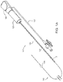
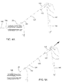
FIG. 1A is a perspective view of an exemplary embodiment of an apparatus for delivering a sealant into a puncture through tissue, including a cartridge carrying the sealant and a positioning member. -
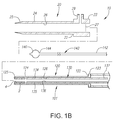
FIG. 1B is an exploded cross-sectional side view of a system for delivering a sealant into a puncture through tissue, including the apparatus ofFIG. 1A and an introducer sheath. -
FIGS. 2A and 2B are cross-sectional views of a distal portion of the apparatus ofFIGS. 1A and1B , with the cartridge in proximal and distal positions, respectively. -
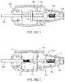
FIGS. 3A(1)-3A(3) are cross-sectional views of a hub of the cartridge ofFIG. 1A showing components of an auto advance device therein in an inactive position. -
FIGS. 3B(1)-3B(3) are cross-sectional views of a hub of the cartridge ofFIG. 1A showing components of the auto advance device ofFIGS. 3A(1)-3A(3) in an active position. -
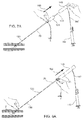
FIGS. 4A, 5A ,6A ,7A, and 8A are partial cross-sectional views of a patient's body illustrating a method of using the system ofFIG. 1A for sealing a puncture through tissue. -
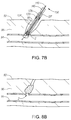
FIGS. 4B, 5B ,6B ,7B, and 8B are cross-sectional detail views of the method ofFIGS. 4A, 5A ,6A ,7A, and 8A . -
FIGS. 6C and 6D are perspective views of a proximal end of a hub on the cartridge of the system ofFIG. 1A before and after the hub passes a marker on the positioning member, respectively. -
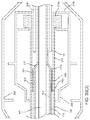
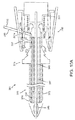
FIG. 9 is a cross-sectional view of another embodiment of an apparatus for delivering sealant into a puncture through tissue, including a tamping device. -
FIGS. 10A-10B are cross-sectional views of the apparatus ofFIG. 9 in a first position. -
FIGS. 11A-11B are cross-sectional views of the apparatus ofFIG. 9 in a second and a third position, respectively. -
FIGS. 12A-12C are cross-sectional views of another embodiment of an apparatus for delivering sealant into a puncture through tissue, including a tamping device employing a latch gate configuration. -
FIG. 13 is a cross-sectional view of another embodiment of an apparatus for delivering sealant into a puncture through tissue, including a tamping device in a position, similar to the embodiment shown inFIG. 11B . -
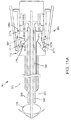
FIG. 14 is a cross-sectional view of yet another embodiment of an apparatus for delivering sealant into a puncture through tissue, including a tamping device in a position, similar to the embodiment shown inFIG. 11B . -
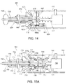
FIGS. 15A-15C are cross-sectional views of an apparatus for delivering a sealant device into a puncture through tissue including a tamping device employing complementary latches. - Turning to the drawings,
FIGS. 1A and1B show an exemplary embodiment of anapparatus 101 and asystem 10, respectively, for sealing a puncture through tissue. Generally, as shown inFIG. 1A , theapparatus 101 includes a cartridge or othertubular member 120, and a positioning orocclusion member 140 including apositioning member housing 148. As best seen inFIG. 1A , thecartridge 120 includes asealant 2 therein, a plunger, tamping member, advancing member, orother pusher member 130 carried by thecartridge 120, and acartridge hub 123. As shown inFIG. 1B , theapparatus 101 may be part of asystem 10, e.g., which may also include a delivery, access, procedure, introducer, orother sheath 20. Optionally, thesystem 10 may include one or more other components, e.g., a needle, guidewire, and/or other instrument(s) for creating a puncture, a syringe or other source of inflation media and/or vacuum, and/or a source of additional sealing compound (not shown). - As best seen in
FIG. 1B , theintroducer sheath 20 may be a generally tubular body including aproximal end 22, adistal end 24 sized for insertion into a puncture through tissue, and alumen 26 extending between the proximal anddistal ends introducer sheath 20 may be formed from a substantially rigid, semi-rigid, and/or flexible tubular body including ahub 23 on theproximal end 22. Theintroducer sheath 20 may have sufficient length to extend from a patient's skin through any intervening tissue into a blood vessel or other body lumen, e.g., having a length between about ten centimeters and twenty centimeters (10-20 cm), and may have an outer diameter between about 1.6 millimeters and four millimeters (1.6-4 mm). Thedistal end 24 may be tapered and/or may include a substantially atraumaticdistal tip 25 for facilitating advancement through tissue and/or a puncture. - The
introducer sheath 20 may be formed using known materials and/or methods, e.g., plastic with the tubular body andhub 23 substantially permanently connected together, e.g., using one or more of an interference fit, one or more mating connectors (not shown), bonding with adhesive, sonic welding, and the like. Thehub 23 generally includes one or more seals (not shown) adjacent anopening 27, which may prevent flow of blood or other fluids out of thehub 23 from thelumen 26, yet accommodate insertion of one or more instruments into thelumen 26, such as thecartridge 120 and/orpositioning member 140. Optionally, as shown, thehub 23 may include aside port 29 communicating with thelumen 26, e.g., for coupling a source of saline or other fluid (not shown) to thehub 23. - With additional reference to
FIG. 1B , thecartridge 120 is generally an elongate tubular body including aproximal end 122, adistal end 124 sized for introduction into thelumen 26 of theintroducer sheath 20, and alumen 126 extending between the proximal anddistal ends cartridge 120 may be substantially rigid, semi-rigid, or flexible, e.g., such that thecartridge 120 may be advanced through theintroducer sheath 20 or otherwise into a puncture through tissue. Thecartridge 120 may also include a tapered and/or substantially atraumaticdistal tip 125 and/or an enlarged handle orhub 123 on theproximal end 122. In one embodiment, thehub 123 includes a tamping or auto - advance device, as discussed in more detail below. - Optionally, the
system 10 may include a locking member (not shown) for coupling theintroducer sheath 20 to thecartridge 120 during use such that subsequent movement of thecartridge 120, e.g., proximally during retraction, causes theintroducer sheath 20 to be pulled or otherwise moved along with thecartridge 120. This coupling may prevent accidental proximal movement of thecartridge 120 independent of theintroducer sheath 20, which may otherwise result in deploying thesealant 2 from thecartridge 120 within theintroducer sheath 20, rather than within a puncture itself. Exemplary embodiments of locking elements that may be used are disclosed in co-pendingU.S. patent application 11/864,835, filed September 28, 2007 U.S. Publication No. 2009/0088793 . - The
sealant 2 is provided within the distal portion of thecartridge 120 and thepusher member 130 is provided proximal to thesealant 2 within thecartridge 120. Thesealant 2 may include a biocompatible, bioabsorbable, and/or expandable material, such as a freeze-dried hydrogel. Thesealant 2 may have a solid or hollow cylindrical shape, a rolled sheet shape, a disk shape, or other shapes or cross-sections, such as elliptical, triangular, square, conical, disk, or polygonal shapes. For example, thesealant 2 may be formed from a solid material including alumen 4 extending between proximal and distal ends thereof, as shown inFIG. 1B . Thelumen 4 may be created by rolling a sheet of material around a mandrel, by molding, by boring into, or otherwise removing material from an already formed solid material, and the like. Thelumen 4 may be dimensioned such that thepositioning member 140, a guidewire, and/or other instruments (not shown) may slide or otherwise pass through thesealant 2, as described elsewhere herein. - The
sealant 2 may be substantially homogeneous or may include one or more different materials at one or more locations. For example, in one embodiment, thesealant 2 may include a carrier or core having first and second hydrogel precursors disposed thereon in an unreactive state, which may provide a "sticky" adherent coating when thesealant 2 is exposed to an aqueous environment. In one embodiment, thesealant 2 may be formed from a biocompatible and/or bioabsorbable hydrogel, e.g., polyethylene glycol ("PEG"), or other synthetic material. For example, the hydrogel may include a lyophilized (i.e., freeze-dried) PEG polymer that includes hydrolytically degradable chemical groups, e.g., including a macroporous polymer network, which may uptake fluid and expand when exposed to an aqueous environment. The magnitude of expansion or swelling (pre to post hydration) may be significant, e.g., between about two and ten times (2X-10X) its lyophilized size based on volume. - In addition or alternatively, the
sealant 2 may include pro-thrombotic material, e.g., including one or more biological pro-thrombotics, such as collagen, fibrin, carboxymethylcellulose, oxidized cellulose, alginates, gelatin, or other protein-based material, and/or synthetic materials, such as polyglycolic acids (PGA's), polyactides (PLA's), polyvinyl alcohol, and the like. Optionally, thesealant 2 may include one or more therapeutic and/or pharmaceutical agents, e.g., to promote healing, prevent infection, and/or other adverse medical events, and the like. Such agents may be embedded in the sealant material and/or applied as one or more coatings or layers. Exemplary materials and methods for making and using them are disclosed inU.S. Patent Nos. 6,152,943 ,6,165,201 ,6,179,862 ,6,514,534 ,6,379,373 ,6,703,047 ,7,009,034 ,6,887,974 , and in co-pendingU.S. patent applications Serial Nos. 10/454,362, filed June 4, 2003 US 2004/0249342 ,10/982,387, filed November 5, 2004 US 2006/0034930 ,10/982,384, filed November 5, 2004 US 2006/0099238 , and11/465,791, filed August 18, 2006 US 2007/0231366 . - The
sealant 2 may be disposed within thelumen 126 of thecartridge 120 proximate to thedistal end 124, e.g., immediately adjacent thedistal tip 125. Thus, when advanced into theintroducer sheath 20 or otherwise within the puncture, thesealant 2 may remain out of direct or indirect contact with blood or other bodily fluids along the blood path. Optionally, thecartridge 120 may include a split distal end (not shown), e.g., formed by creating one or more relatively short longitudinal cuts or slots extending proximally from thedistal end 124. The split distal end may facilitate retraction of thecartridge 120 relative to thesealant 2, e.g., by providing extra flexibility at thedistal end 124. Such cuts or slots may allow thedistal end 124 to separate more easily from thesealant 2, e.g., as the sealant begins to expand upon being exposed to an aqueous environment, such as blood or other bodily fluids. Thelumen 126 may be sized such that thecartridge 120 andsealant 2 are slidable relative to one another, e.g., to allow thecartridge 120 to be retracted proximally relative to thesealant 2 and/orpusher member 130. - With further reference to
FIG. 1B , thepusher member 130 may be an elongate tubular body, e.g., a plunger or catheter, including aproximal end 132, adistal end 134 sized for introduction into thelumen 126 of thecartridge 120, and alumen 136 extending between the proximal anddistal ends pusher member 130 may be sized for being slidably received within thelumen 126 of thecartridge 120, although thepusher member 130 may abut or otherwise interact with thehub 123 of thecartridge 120 such that thepusher member 130 is advanced distally when thecartridge 120 is advanced distally. Thedistal end 134 of thepusher member 130 may terminate in a substantially bluntdistal tip 135, e.g., to facilitate contacting, pushing, advancing, tamping, and/or "cinching" thesealant 2 within a puncture, as described further below. In one embodiment, theproximal end 132 of thepusher member 130 interacts with an auto-advance device in thehub 123, as discussed in more detail below. - The
pusher member 130 may be substantially rigid, semi-rigid, and/or substantially flexible, having sufficient column strength to allow proximal movement of thecartridge 120 relative to thesealant 2 without buckling thepusher member 130 and/or to allow thedistal tip 135 of thepusher member 130 to be "tamped" down onsealant 2 within a puncture, e.g., by pushing from theproximal end 132, as described elsewhere herein. Thelumen 136 of thepusher member 130 may be sized to accommodate thepositioning member 140, a guidewire (not shown), a flowable sealing compound, and/or fluid therethrough. As explained elsewhere herein, thepusher member 130 may include an axially compressible or foreshortenable portion, e.g., that may be compressed, yet is biased to extend axially towards its original length. For example, a tampingspring 210 may be provided adjacent theproximal end 132 of thepusher member 130, e.g., between theproximal end 132 and asecondary pusher member 230. Alternatively, the tampingspring 210 may be coupled to and extend from theproximal end 132 of thepusher member 130 without thesecondary pusher member 230. The tampingspring 210 may be compressed by an auto advance device 200 (not shown, seeFIGS. 3A-3B ) within thehub 123 during use, thereby biasing thedistal end 134 of thepusher member 130 to move distally, as explained further below. - With continued reference to
FIGS. 1A and1B , the positioningmember 140 generally is an elongate member including aproximal end 142, adistal end 144, a positioning orocclusion element 146 on thedistal end 144, and ahousing 148 on theproximal end 142. Thepositioning element 146 may be an expandable member, such as a balloon, a wire mesh structure, an expandable frame, and the like. Thepositioning element 146 may be selectively expandable, e.g., using a source of inflation media, a pull wire, and/or other actuator (not shown), operable from theproximal end 142 of thepositioning member 140. - For example, as shown in
FIGS. 1A and1B , the positioning element may be aballoon 146, and thepositioning member 140 may be a tubular body including a lumen (not shown) extending between the proximal anddistal ends balloon 146. For example, a syringe 149 (not shown, seeFIGS. 4A, 5A ,6A ) may communicate with the housing 148 (and consequently the lumen and interior of the balloon 146) viatubing 147 connected to a port on thehousing 148. Optionally, the positioningmember 140 may include an internal pull wire and piston arrangement (not shown) that causes theballoon 146 to shorten during expansion and extend during collapse. Exemplary embodiments of positioningmembers 140 including balloons that may be used are disclosed in co-pendingU.S. patent applications Serial Nos. 10/454,362, filed June 4, 2003 US 2004/0249342 ,11/112,877, filed April 22, 2005 US 2006/0253072 , and11/112,971, filed April 22, 2005 US 2008/0009794 . - Alternatively, the
positioning element 146 may be biased to an enlarged condition, but may be compressed to a contracted condition, e.g., by an overlying sleeve or other constraint (not shown). The constraint may be removed to expose the positioning element, allowing the expandable element to automatically expand to the enlarged condition. Additional information on expandable structures that may be provided on thepositioning member 140 may be found inU.S. Patent Nos. 6,238,412 ,6,635,068 , and6,890,343 . - Optionally, the positioning
member 140 may include a transition cuff (not shown) on thedistal end 144 adjacent and distal to thepositioning element 146. The transition cuff may comprise a flexible material similar to the structure of material used in thepositioning element 146, e.g., as described elsewhere herein. The transition cuff may provide theapparatus 101 with a seal to minimize exposure of thesealant 2 to fluids during introduction and/or may provide an atraumatic tip to lessen injury to the vessel during initial insertion of theapparatus 101 into the puncture and vessel. During expansion of thepositioning element 146, the transition cuff may be displaced off the distal end of thepositioning element 146 and fold adjacent to thepositioning element 146. A lubricious coating may be applied to the transition cuff and/orpositioning element 146 to ease the folding of the transition cuff during the expansion of thepositioning element 146. Additional information on transition cuffs and systems and methods including them may be found in co-pending application Serial No.11/854,534, filed September 12, 2007 U.S. Publication No. 2008/0082122 . - Turning to
FIGS. 2A and 2B , theapparatus 101 may be used to position and deliver thesealant 2 within a puncture, e.g., extra-vascularly just above or otherwise adjacent to an arteriotomy in a blood vessel or other body lumen communicating with a puncture, as described further elsewhere herein. In one embodiment, as shown inFIG. 2A , the cartridge 120 (along with thepusher member 130 and sealant 2) may be initially provided on theproximal end 142 of thepositioning member 140. For example, the housing 148 (not shown inFIGS. 2A and 2B , seeFIG. 1A ) on thepositioning member 140 and thehub 123 on thecartridge 120 may be initially connected to one another, e.g., using one or more releasable detents (not shown) and the like. Thecartridge 120 may be slidable distally along the positioningmember 140, e.g., by disconnecting thehub 123 from thehousing 148, and then advancing thehub 123 and thecartridge 120 until thedistal end 124 of thecartridge 120 is disposed adjacent thepositioning element 146, as shown inFIG. 2B . For example, the detents may simply separate from one another when thehub 123 is advanced away from thehousing 148 with sufficient force. Alternatively, one of thehub 123 andhousing 148 may include an actuator or lock (not shown) that may be activated to separate the detents and/or otherwise allow thecartridge 120 to be advanced relative to thepositioning member 140. Alternatively, thecartridge 120 andpusher member 130 may be initially provided adjacent thedistal end 144 of thepositioning member 140, as shown inFIG. 2B . - Optionally, the positioning
member 140 and/orpusher member 130 may include one or more elements that engage when thecartridge 120 reaches a predetermined location when advanced distally along the positioningmember 140, e.g., to limit subsequent proximal movement of thepusher member 130 relative to thepositioning member 140. For example, as shown inFIGS. 2A and 2B , the positioningmember 140 may include a locking element, e.g., a stepped-down region orrecess 145 at a predetermined location and thepusher member 130 may include a living hinge, tab, orother latch element 137 on theproximal end 132. Alternatively, the lockingelement 145 may be a ring, tab, or other raised element (not shown) over which thelatch element 137 may pass distally, yet may subsequently engage thelatch element 137 to prevent proximal movement of thepusher member 130, as shown inFIG. 3B(3) and described further below. For example, thelatch element 137 may simply be an annular notch in theproximal end 132 of thepusher member 130 to bias the proximal end inwardly. - As an alternative to the latch element(s) 137, the
pusher member 130 may simply include a relatively narrow region on theproximal end 132. Further alternatively, the latch element(s) 137 may be replaced by a separate collar or sleeve, one or more inwardly oriented detents, and the like (not shown) attached to or otherwise formed on theproximal end 132 of thepusher member 130. In an exemplary embodiment, the lockingelement 145 may be defined by a reduced diameter region on thepositioning member 140, e.g., formed by providing a larger tube around a smaller inner tube or by machining, etching, or otherwise removing a portion of the tubular body of thepositioning member 140 distal to the reduced region. Thepusher member 130 may include a corresponding element (also not shown) that may allow distal advancement but prevent proximal retraction once thepusher member 130 is advanced a predetermined distance, i.e., over the lockingelement 145. Exemplary embodiments of cooperating elements are disclosed inU.S. Publications No. 2006/0099238 and2009/0088793 . - The reduced region or
other locking element 145 may be provided at a predetermined location on thepositioning member 140, e.g., a predetermined distance from thepositioning element 146 that corresponds to a length of thepusher member 130, e.g., a relaxed or compressed length of thepusher member 130. As the cartridge 120 (and consequently the pusher member 130) is advanced over the positioningmember 140, e.g., until thesealant 2 is disposed adjacent thepositioning element 146, thelatch element 137 may pass freely over the lockingelement 145. Thereafter, thelatch element 137 may prevent thepusher member 130 from being retracted again past the lockingelement 145 due to the blunt edge of thelatch element 137 abutting the lockingelement 145. - Alternatively, the
pusher member 130 may be fixed relative to thepositioning member 140, for example, mechanically bonded, chemically bonded, interference fit, and the like. For example, thedistal end 134 of thepusher member 130 may be fixed a predetermined distance proximal to thepositioning element 146, e.g., to provide thesealant 2 immediately adjacent thepositioning element 146, as shown inFIG. 2B . Additional information on such alternatives and methods for making and using them may be found inU.S. Publication No. 2008/0082122 . - In one embodiment, the
hub 123 of thecartridge 120 includes a tamping orauto advance device 200, depicted in detail inFIGS. 3A and 3B . Generally, theauto advance device 200 includes aslider tube 204 slidable within thehousing 202 and coupled to thecartridge 120. Theslider tube 204 may be biased distally relative to thehousing 202 such that movement of thecartridge 120, sealant 2 (not shown, seeFIG. 1A ), andpusher tube 130 is initially coupled to thehousing 202. Thus, when thehub 123 is directed distally, thecartridge 120,sealant 2, andpusher tube 130 are also directed distally. However, theslider tube 204 may be movable proximally within thehousing 202, e.g., when the bias is overcome, to allow thecartridge 120 to move proximally relative to thesealant 2 andpusher member 130, e.g., during deployment of thesealant 2, as described further below. - As best seen in
FIG. 3A(3) , theproximal end 132 of thepusher member 130 may be disposed within thehousing 202 before theapparatus 101 is used. As shown inFIGS. 3A(1)-3A(3) , theauto advance device 200 may include anauto advance spring 206 adjacent theslider tube 204, e.g., for biasing theslider tube 204 distally, yet allowing theslider tube 204 to move proximally within thehousing 202 when the spring bias is overcome. It will be appreciated that other springs or biasing mechanisms may be provided for biasing theslider tube 204 distally within thehousing 202, yet allowing proximal movement relative to thehousing 202. In addition, as best seen inFIGS. 3A(1) and 3A(2) , theauto advance device 200 may include auto advancespring support tubing 208 fixed relative to thehousing 202 and around which theauto advance spring 206 may be disposed. Theslider tube 204 may slide over thesupport tubing 208 when theslider tube 204 is directed proximally within thehousing 202. - In addition, the
auto advance device 200 may include one or more additional components, e.g., coupled to thepusher member 130,cartridge 120, and/orhousing 202. For example, thepusher tube spring 210 may be disposed between thesecondary pusher member 230 and theproximal end 132 of thepusher member 130. Thepusher tube spring 210 may be coupled to thepusher member 130 and thesecondary pusher member 230, e.g., by one or more of an interference fit, bonding with adhesive, and the like. In this embodiment, theproximal end 132 of thepusher member 130 is positioned in thedistal end 210a of the tampingspring 210 and the distal end of thesecondary pusher member 230 is positioned within theproximal end 210b of the tampingspring 210. Thus, the outside diameters of thepusher members spring 210. - Optionally, the
auto advance device 200 may include an inner cartridge or tampingtube 212 disposed around thepusher tube spring 210 and thesecondary positioning member 230. As best seen inFIGS. 3A(1) and 3A(2) , theinner cartridge 212 may be disposed concentrically within theslider tube 204. Theinner cartridge 212 may be coupled to theslider tube 204 such that theinner cartridge 212 moves with theslider tube 204. For example, theinner cartridge 212 may include ahub 212a, which may be received in a corresponding pocket orrecess 204a in theslider tube 204, thereby coupling movement of theinner cartridge 212 to theslider tube 204. Theinner cartridge 212 may also protect and/or conceal thepusher tube spring 210 therein and may be coupled to theproximal end 122 of thecartridge 120. As best seen inFIG. 3A(2) , theinner cartridge 212 may have an outer diameter similar to the diameter of thecartridge 120, e.g., such that theinner cartridge 212 abuts theproximal end 122 of thecartridge 120. Alternatively, theinner cartridge 212 may be attached to theproximal end 122 of thecartridge 120. In a further alternative, theinner cartridge 212 andcartridge 120 may be provided as a single piece, e.g., such that theinner cartridge 212 is merely an extension (not shown) extending proximally from thecartridge 120. - In
FIGS. 3A(1)-3A(3) , theauto advance device 200 is in an "inactive" position where thesprings FIG. 3A(2) ). In the inactive position, theslider tube 204 may be biased by theauto advance spring 206 such that aflange 218 extending from theslider tube 204 abuts or otherwise contacts adistal rib 214 of thehousing 202, as best seen inFIG. 3A(1) . Thus, theslider tube 204 may be positioned in a distal portion of thehousing 202 in the inactive position. In addition, in the inactive position, thesupport tubing 208 may be positioned proximally to and/or substantially entirely outside of theslider tube 204, also as best seen inFIG. 3A(1) . As shown inFIG. 3A(3) , thesecondary pusher member 230 is located proximal to thelocking element 145 in the inactive position, e.g., such that movement of thepusher member 130 andsecondary pusher member 230 are initially coupled to movement of thecartridge 120. -
FIGS. 3B(1)-3B(3) show theauto advance device 200 in an "active" position where thesprings housing 202, including thecartridge 120,sealant 2,pusher member 130, andslider tube 204 have been advanced distally relative to thepositioning member 140 such that thesecondary pusher member 202 has been advanced distally past the lockingelement 145, as best seen inFIG. 3B(3) . In the active position, theauto advance spring 206 is compressed between aproximal rib 216 of thehousing 202 and the proximal end of theslider tube 204, and theslider tube 204 is positioned in a proximal portion of thehousing 202. For example, thecartridge 120 andhub 123 may be advanced relative to thepositioning member 140 until thecartridge 120 cannot be advanced further, whereupon additional distal movement of thehub 123 causes theauto advance spring 206 to compress as the slider tube 204 (andproximal end 122 of the cartridge 120) moves proximally within thehousing 202. In addition, in the active position, thesupport tubing 208 may extend into theslider tube 204 and abut thesecondary pusher member 230, thus compressing the tampingspring 210 as thepusher member 130 moves proximally with thecartridge 120, as best seen by comparingFIG. 3B(2) withFIG. 3A(2) . When compressed, the tampingspring 210 applies a distal force against thepusher member 130, biasing thepusher member 130 distally against thesealant 2. As explained further below, as thesealant 2 expands and/or softens, e.g., upon exposure to an aqueous environment, the constant force applied by the tampingspring 210 causes thepusher member 130 to automatically advance distally, exerting constant force on thesealant 2, thereby tamping or "cinching" thesealant 2 between thepusher member 130 and thepositioning element 146 during expansion. This method is described in greater detail below. - In the embodiment shown, the
springs auto advance device 200 may include other spring arrangements or biasing mechanisms, such as an extension spring, leaf spring, and the like (not shown), e.g., that may be in a compressed condition at its lower energy state length and in an expanded condition when a load is applied. - Turning to
FIGS. 4A-8B , an exemplary method is shown for sealing apuncture 90, e.g., using thesystem 10 described above to deliver asealant 2, e.g., to achieve hemostasis within thepuncture 90. Generally, thepuncture 90 extends from a patient'sskin 92 through interveningtissue 96, e.g., to abody lumen 94. In an exemplary embodiment, thepuncture 90 may be a percutaneous puncture communicating with ablood vessel 94, such as a femoral artery, carotid artery, and the like. - In an exemplary method, the
puncture 90 may be created using known procedures, e.g., using a needle, guidewire, one or more dilators, and the like (not shown). Then, as depicted inFIGS. 4A and4B , anintroducer sheath 20 may be advanced through thepuncture 90 into thevessel 94, e.g., over a guide wire (not shown) placed through thepuncture 90 into thevessel 94. Theintroducer sheath 20 may provide access into thevessel 94 for one or more instruments, e.g., to allow one or more diagnostic, therapeutic, and/or other interventional procedures to be performed via thevessel 94. Upon completing the procedure(s) via thevessel 94, any such instrument(s) may be removed from thepuncture 90, leaving theintroducer sheath 20 extending through thepuncture 90 into thevessel 94. - The
distal end 144 of thepositioning member 140 may be introduced into thepuncture 90, e.g., through thelumen 26 of theintroducer sheath 20, with thepositioning element 146 in a collapsed condition, as shown inFIG. 4B . As shown inFIG. 4A , thecartridge 120 andcartridge hub 123, along with thesealant 2 and pusher member 130 (not shown inFIG. 4A for clarity, see, e.g.,FIGS. 1A-2B ), may be provided initially on the proximal end of thepositioning member 140, e.g. near the positioningmember housing 148. Thus, thedistal end 124 of thecartridge 120 may initially be located outside thepuncture 90 when thepositioning member 140 is advanced into thepuncture 90. Alternatively, thecartridge 120 may be carried on thedistal end 144 of thepositioning member 140, e.g., as shown inFIG. 2B , such that the cartridge 120 (along with thesealant 2 and pusher member 130) is introduced simultaneously with the positioningmember 140, as described inU.S. Publication No. 2008/0082122 . - Still referring to
FIGS. 4A and4B , thedistal end 144 of thepositioning member 140 may be inserted through the puncture 90 (via the introducer sheath 20) and into thevessel 94. Optionally, the positioningmember 140 may include one or more markers (not shown) that may be disposed adjacent theproximal end 22 of theintroducer sheath 20 when thedistal end 144 extends beyond thedistal end 24 of theintroducer sheath 20, e.g., to provide a visual indication that thepositioning element 146 is disposed within thevessel 94 beyond thedistal end 24 of theintroducer sheath 20. Once thepositioning element 146 is disposed within thevessel 94, i.e., beyond thedistal end 24 of theintroducer sheath 20, thepositioning element 146 may be expanded to an enlarged condition, as shown inFIG. 4A and as shown in phantom inFIG. 4B . After expanding thepositioning element 146, the positioningmember 140 may be at least partially withdrawn until thepositioning element 146 contacts the wall of the vessel 94 (shown inFIGS. 5A and5B ), e.g., to substantially seal thevessel 94 from thepuncture 90. - In an exemplary method, this may involve a two-step process (although it may be completed in a single continuous action). First, with the
positioning element 146 expanded within thevessel 94, as shown inFIG. 4A and in phantom inFIG. 4B , the positioningmember 140 may be withdrawn until thepositioning element 146 contacts thedistal end 24 of theintroducer sheath 20, which may provide a first tactile feedback to the user (i.e., that thepositioning element 146 has contacted theintroducer sheath 20, e.g., based upon the increased weight and/or resistance to proximal movement). After encountering the first tactile feedback, the positioningmember 140 may be withdrawn further until thepositioning element 146 contacts the wall of thevessel 94 and resists further withdrawal, thereby providing a second tactile feedback. Theintroducer sheath 20 may be pulled proximally by thepositioning element 146 as thepositioning member 140 is withdrawn, e.g., until thepositioning element 146 contacts the wall of thevessel 94 and thedistal end 24 of theintroducer sheath 20 is withdrawn from thevessel 94 into thepuncture 90, as shown inFIGS. 5A and5B . - Alternatively, a tension indicator assembly (not shown) may be used for more accurate control of the proximal tension on the
positioning member 140. Exemplary tension indicator assemblies are disclosed in co-pendingU.S. patent application 12/098,380, filed April 4, 2008 U.S. Publication No. 2009/0254110 . - The desired amount of proximal tension may be maintained manually or using a tension device (not shown) to provide temporary hemostasis, e.g., during the subsequent steps. Exemplary tension devices are disclosed in co-pending
U.S. patent application 10/806,952, filed March 22, 2004US 2004/0267308 . - Turning to
FIGS. 6A and6B , the cartridge 120 (carrying thesealant 2, shown inFIG. 6B ) may then be advanced distally over the positioningmember 140 into thepuncture 90, as indicated byarrow 164. For example,FIG. 6A illustrates the user grasping thehub 123 and pushing thehub 123, e.g., to separate thehub 123 from the positioningmember housing 148 and advance thecartridge 120 distally over the positioningmember 140 and into theintroducer sheath 20. Thecartridge 120 may be advanced into theintroducer sheath 20 until thedistal end 124 of thecartridge 120 contacts the expandedpositioning element 146, as shown inFIG. 6B . - In one embodiment, the
cartridge 120 may be advanced through theintroducer sheath 20 until ahub 123 of thecartridge 120 abuts ahub 23 on theintroducer sheath 20. In another embodiment, thecartridge 120 may be advanced until a locking element (not shown) engages, thereby coupling thecartridge 120 to theintroducer sheath 20. - In the embodiment where the
cartridge hub 123 includes theauto advance device 200, theauto advance device 200 is initially in the inactive position (not shown, see, e.g.,FIGS. 3A(1)-3A(3) ), during distal advancement of thehub 123 and thecartridge 120. Thus, distal advancement of thehub 123 causes corresponding advancement of thecartridge 120. Once thecartridge 120 contacts the expandedpositioning element 146, further distal advancement of thecartridge 120 is prevented by thepositioning element 146. - Then, when the
hub 123 is advanced further distally relative to thecartridge 120 theauto advance device 200 may be activated. For example, as shown inFIG. 6C , thecartridge 120 andhub 123 may be advanced until amarker 220 on thepositioning member 140 becomes initially exposed, which may indicate that thedistal end 124 of thecartridge 120 is adjacent to or in contact with the expandedpositioning element 146. At this stage, as shown inFIGS. 3A(1)-3A(3) , theslider tube 204 may be in the distal position within thehousing 202 of thehub 123. Thehub 123 may then be advanced further, e.g., at least partially over thecartridge 120, as shown inFIGS. 3B(1)-3B(3) . - As shown in
FIG. 6D , as thehub 123 is advanced, themarker 220 on thepositioning member 140 may become entirely exposed, thereby providing a visual indicator to the user confirming that theauto advance device 200 has been activated. It will be appreciated that other visual and/or audible indicators (not shown) may be provided on thepositioning member 140 and/orhub 123 to provide confirmation when thesecondary pusher member 230 has been sufficiently advanced and/or the tampingspring 210 has been compressed. Since thecartridge 120 is prevented from moving distally, distal advancement of thehub 123 causes theslider tube 204, which is fixed to thecartridge 120, to slide into a proximal portion of thehub 123 so that the proximal end of theslider tube 204 contacts the proximal end of thehub 123, as shown inFIGS. 3B(1)-3B(3) . Distal advancement of thehub 123 further causes theauto advance spring 206 to compress between the proximal end of theslider tube 204 and theproximal rib 216 of thehousing 202. In the active position, the auto advancespring support tubing 208 extends into the tampingtube 212, thereby pushing thesecondary pusher member 230 towards theproximal end 132 of thepusher member 130, which causes the tampingspring 210 to compress. As thesecondary pusher member 230 moves towards theproximal end 132 of thepusher member 130, thelatch element 237 passes over the raisedelement 145 on thepositioning member 140. Thereafter, thesecondary pusher member 230 is prevented from retracting proximally relative to thepositioning member 140 and the compression of the tampingspring 210 is maintained, thus providing constant force to thesealant 2 via thepusher member 130. - Returning to
FIGS. 6A and6B , once thecartridge 120 andhub 123 have been advanced to place thesealant 2 in the desired position within the puncture 90 (best seen inFIG. 6B ), thecartridge 120 may be retracted, e.g., by pulling proximally on thehub 123, as indicated byarrow 165 inFIG. 7A . If the optional locking element (not shown) has coupled theintroducer sheath 20 to thecartridge 120, this action also withdraws theintroducer sheath 20 from thepuncture 90. Alternatively, theintroducer sheath 20 may be pulled, contacting thehub 123 and thereby withdrawing thecartridge 120 along with theintroducer sheath 20. As thecartridge 120 is retracted, thepusher member 130 may remain in place (e.g., due to the locking element 145) to prevent substantial proximal movement of thesealant 2, thesealant 2 is exposed within thepuncture 90, as shown inFIG. 7B . In one embodiment, as described above, when thecartridge 120 is retracted, thelatch element 237 on thesecondary pusher member 230 may abut thelocking element 145, thereby preventing substantial proximal retraction of thesecondary pusher member 230 and thesealant 2 adjacent to thedistal end 134 of thepusher member 130. - When the
sealant 2 is exposed within thepuncture 90, thesealant 2 may be exposed to blood and/or other body fluids within thepuncture 90. This exposure may cause thesealant 2 to absorb fluid, soften and/or expand within thepuncture 90, e.g., to provide hemostasis. Theauto advance device 200 may cause thepusher tube 130 to automatically advance as space permits, e.g., when thesealant 2 begins to swell and/or soften, thereby compressing or "cinching" thesealant 2 between thepusher tube 130 and thepositioning element 146. Optionally, if desired, thepusher member 130 may be advanced manually to compress thesealant 2 further, e.g., against thepositioning element 146. This may cause thesealant 2 to expand further radially outwardly and/or press thesealant 2 against the arteriotomy, e.g., to enhance sealing thepuncture 90 from thevessel 94. Optionally, thepusher member 130 may include one or more distance markers (not shown) on or adjacent theproximal end 132, and thepusher member 130 may be advanced into the puncture 90 a desired distance, which may be confirmed by monitoring the distance markers. - Once the
sealant 2 has been exposed for sufficient time and/or tamped by thepusher member 130, thepositioning element 146 may be collapsed, and thepositioning member 140 withdrawn from thevessel 94 andpuncture 90, e.g., by pulling the collapsedpositioning element 146 through thesealant 2 andpusher member 130, as depicted byarrow 166 inFIG. 8A . In an exemplary embodiment, theexpandable member 146 may have a profile not more than about 0.875 millimeter (035 inch) to facilitate removal of thepositioning member 140 without substantially disturbing the deployedsealant 2. Thepusher member 130 may be maintained substantially stationary during withdrawal of thepositioning member 140, e.g., to prevent migration and/or dislodgment of thesealant 2 within thepuncture 90. For example, as shown inFIG. 8A , thepusher member 130 may be maintained substantially stationary by a user grasping thepusher member 130 during withdrawal of thepositioning member 140. In the embodiment where thesystem 10 includes theauto advance device 200, the user may grasp thepusher member 130 rather than thesecondary pusher member 230 so that the user may have more control of the force applied to thesealant 2 during withdrawal of thepositioning member 140. In addition, in embodiments where thesealant 2 includes an adherent layer, the "sticky" adherent layer may also aid in securing thesealant 2 to the surrounding tissue. Once the positioningmember 140 is completely removed, thepusher member 130 may be removed from thepuncture 90, leaving thesealant 2 within thepuncture 90, as shown inFIG. 8B . - Optionally, after removing the
positioning member 140, liquid hydrogel or other sealing compound, or other material may be delivered into thepuncture 90, e.g., above and/or around thesealant 2, to assist in achieving hemostasis. For example, such material may be delivered via thelumen 136 of thepusher member 130 and/or by introducing another delivery device (not shown) into thepuncture 90, e.g., after removing thepusher member 130. - Turning now to
FIGS. 9-11B , another exemplary embodiment of anapparatus 301 is shown for delivering asealant 302 into a puncture through tissue including atamping device 385. Similar to other embodiments herein, theapparatus 301 is shown schematically and not to scale, e.g., with the radial and axial dimensions exaggerated to facilitate identification of the components of theapparatus 301. Theapparatus 301 includes an elongate positioning orocclusion member 340, acartridge 370, and acatheter hub 380. The positioningmember 340 includes aproximal end 342, adistal end 344, and anexpandable positioning element 346, e.g., similar to previous embodiments, on thedistal end 344. Similar to previous embodiments, optionally, atransition cuff 350 may be located adjacent to the distal end of theexpandable member 346. - The
cartridge 370 generally includes an outertubular member 373, asealant 302, aninner pusher member 330, and amiddle hub 376. The outertubular member 373 includes alumen 360 extending between aproximal end 372 and adistal end 374 thereof. The outertubular member 373 is movable relative to theinner pusher member 330, which is slidably disposed within the outertubular member 373. Themiddle hub 376 may be attached to theproximal end 372 of the outertubular member 373. - The
sealant 302 andinner pusher member 330 are similar to previous embodiments. Theinner pusher member 330 includes a lumen extending between aproximal end 332 and adistal end 334. Theinner pusher member 330 may include a peel away lock 390 ordetents 336, e.g., as shown inFIGS. 10A-10B , for initially limiting proximal movement of the outertubular member 373, e.g., until after removing thelock 390. - The
middle hub 376 includes amain cylinder 371, a firstconical surface 377a, and a secondconical surface 377b. Alatching detent 375 is disposed between the first and secondconical surfaces main cylinder 371 includes aproximal ridge 371a, and adistal surface 371b. The firstconical surface 377a is tapered from theproximal ridge 371a to thelatching detent 375. The distal end of the secondconical surface 377b includes a diameter larger than the proximal end of the firstconical surface 377a thereby creating thelatching detent 375. Alternatively, the firstconical surface 377a may be tapered using multiple angles or may be tapered gradually. - The
catheter hub 380 includes anouter housing 380a including proximal anddistal ends proximal end 342 of thepositioning member 340. For example, thecatheter hub 380 may include aninner housing 380b fixed relative to theouter housing 380a and coupled to a handle orballoon inflator 396 on thepositioning member 340. Thehub 380 may also include atamping device 385,latch 387, and atamping spring 381 disposed between the tampingdevice 385 and theballoon inflator 396. Thecatheter hub 380 may further include centeringsurfaces 386, e.g., on theinner housing 380b. The material of thecatheter hub 380 and other components may be formed from suitable durable plastics, metals, and/or composite materials. During operation of theapparatus 301, the interior of the handle orballoon inflator 396 may communicate via a lumen (not shown) of thepositioning member 340 with the interior of the expandable member 346to provide a fluid to expand theexpandable member 346, e.g., similar to other embodiments described elsewhere herein. Optionally, thehandle 396 may include a tension indicator (not shown), e.g., also similar to the other embodiments described herein. - The
tamping device 385 includes aproximal surface 385a, adistal surface 385b, aproximal nub 385c, and arecess 385d. Therecess 385d extends partially through thetamping device 385 between thedistal surface 385b and a mostdistal portion 385e ofproximal nub 385c. Therecess 385d is sized to receive theproximal end 332 of theinner pusher member 330 therein without allowing theinner pusher member 330 to pass entirely through thetamping device 385. - The
latch 387 includes aproximal arm 387a, adistal arm 387b, and anintermediate arm 387c. The proximal, distal, andintermediate arms intermediate tip distal tip 388b may be shaped to mate with thelatching detent 375 of themiddle hub 376, and theintermediate tip 388c may be shaped with a nub for making initial contact with theproximal end 378 of themiddle hub 376. Acircular spring clip 383 abuts theproximal arm 387a to bias theproximal arm 387a radially inwardly (away from theinner housing 380b. The inwardly biasedproximal arm 387a causes theproximal tip 388a to prevent distal movement of thetamping device 385 when thelatch 387 is in the position shown inFIG. 9 . - The centering surfaces 386 are located proximally to the
distal end 384. The centering surfaces 386 may be conically shaped and/or otherwise sized and/or shaped for cooperating withconical surfaces middle hub 376. The cooperation of centeringsurfaces 386 withconical surfaces middle hub 376 to thecatheter hub 380. -
FIG. 9 shows theapparatus 301 in a first position, e.g., where thecartridge 370 is disposed adjacent adistal end 344 of thepositioning member 340. This first position may be a configuration in which theapparatus 301 is delivered from a manufacturer to a user. In the first position, thetransition cuff 350, if included, is fully extended over thedistal end 374 of the outertubular member 373. Further, in the first position, theexpandable member 346 may be fully disposed within thelumen 376 of the outertubular member 373, thetamping device 385 may rest against theproximal tip 388a of theproximal arm 387a, and the tampingspring 381 may be compressed. - Turning to
FIG. 10A , theapparatus 301 ofFIG. 9 is shown in a second position limited by a peel awaylock 390. Alternatively, theapparatus 301 may be provided to the user initially in the second position, i.e., with thecartridge 370 disposed adjacent thecatheter hub 380 but without activating thetamping device 385. For example, proximal movement of thecartridge 370 into thecatheter hub 380 past the second position may be prevented until the peel away lock 390 is removed. The peel away lock 390 includes a passage extending between aproximal end 392 and adistal end 394 that surrounds theinner pusher member 330. The peel away lock 390 may be disposed between theproximal end 378 of themiddle hub 376 and thedistal surface 385b of thetamping device 385. In the second position, thecartridge 370 may be positioned proximally relative to theexpandable member 346 such that theexpandable member 346 is fully exposed distal to thedistal end 374. In addition, in the second position, the distal end of thesealant 302 may be disposed adjacent thedistal end 374 of thecartridge 370, and thelatch 387 may remain in contact with thedistal surface 385b of thetamping device 385. - Turning to
FIG. 10B , an alternative embodiment of the apparatus 301' is shown that is generally similar to the embodiment ofFIGS. 9 and10A . Similar toFIG. 10A , the apparatus 301' is shown in the second position; however, unlike theapparatus 301 that is only limited from further proximal movement, the apparatus 301' is positively locked in the second position by a lockingbar 379a.' The apparatus 301' also includes a modified middle hub 376' and a modifiedinner pusher member 330.' The modified middle hub 376' includes a pushbutton 379' coupled to the lockingbar 379a.' The pushbutton 379' and the lockingbar 379a' are disposed within a lumen 379b' extending between an outer and inner surface of themain cylinder 371.' The pushbutton 379' may be spring loaded to bias the lockingbar 379a' into a detent 336' on thepusher member 330.' Thepushbutton 379,' familiar to those of ordinary skill in the art, may be a single action type or a double action type used to retract the lockingbar 379a' from thedetent 336.' The spring loaded lockingbar 379a' may be extended into the detent 336' when thepositioning member 340,'sealant 302,' and inner pusher member 330' are advanced in a distal direction until the lockingbar 379a' aligns with thedetent 336.' The lockingbar 379a' prevents further proximal movement of the cartridge 370' until the pushbutton 379' is pressed to retract the lockingbar 379a.' As shown, in the second position, the tamping device 385' remains in contact with thelatch 387.' - Turning now to
FIG. 11A , after removing thelock 390, theapparatus 301 ofFIGS. 9 and10A is shown in a third position, i.e. at a trigger point, which is a frozen instant in time when thetamping device 385 is initially activated. After releasing thecartridge 370, e.g., by removing thelock 390 or releasing thepushbutton 379,' thecartridge 370 may be moved proximally to expose thesealant 302. As thecartridge 370 enters thecatheter hub 380, theconical surfaces surfaces 386 to align themiddle hub 376 with thecatheter hub 380. Theproximal end 378 of themiddle hub 376 first touches theintermediate tip 388c of theintermediate arm 387c, causing thelatch 387 to rotate. The latch contact generally occurs before theconical surfaces surfaces 386 have fully engaged each other. - Continued proximal movement of the
cartridge 370 into thecatheter hub 380 to expose thesealant 302 causes theproximal arm 387a andproximal tip 388a to rotate upward away from thetamping device 385, thereby releasing thetamping device 385, as explained further below. Also at the trigger point, thedistal arm 387b anddistal tip 388b may rotate down into thelatching detent 375 to secure themiddle hub 376 to thecatheter hub 380, thereby securing thecartridge 370 relative to thecatheter hub 380 in a latched position. - As shown in
FIG. 11A , theexpandable member 346 may have been previously expanded and at least partially withdrawn within a body lumen (not shown) as discussed elsewhere herein until the expandedexpandable member 346 substantially seals the body lumen from a puncture (also not shown). - Turning now to
FIG. 11B , theapparatus 301 is shown in a third position after the trigger point ofFIG. 11A , i.e., with thesealant 302 being tamped and/or compressed. Thesealant 302 is tamped between thedistal end 334 of theinner pusher member 330, which is biased to move distally, and the expandedexpandable member 346. As can be seen, thetamping device 385 is released when thelatch 387 is rotated to disengage theproximal arm 387a from thedistal surface 385b of thetamping device 385. The tampingspring 381 biases theinner pusher member 330 distally because theproximal end 332 of theinner pusher member 330 is disposed within therecess 385d, thereby biasing thedistal end 334 of theinner pusher member 330 distally to compress thesealant 302 towards the expandable member 346 (and/or against an arteriotomy, not shown). The outer surface of thetamping device 385 maintains theproximal arm 387a in an upwardly rotated position, thereby preventing thelatch 387 from moving from the latched position. - Thereafter, once the
sealant 302 is sufficiently compressed and/or hydrated within the puncture, thecatheter hub 380 may be pulled proximally, thereby withdrawing thecartridge 370 from the puncture, leaving theinner pusher member 330 andsealant 302 within the puncture around the positioningmember 340, similar to the previous embodiments. Theexpandable member 346 may then be collapsed and thepositioning member 340 removed through thesealant 302 andinner pusher member 330, also similar to the previous embodiments. Finally, theinner pusher member 330 may be removed, leaving the sealant within the puncture. - Turning now to
FIG. 12A-12C , an alternative embodiment of anapparatus 401 is shown for sealing a puncture. Theapparatus 401 generally includes an elongate occlusion orpositioning member 440, acartridge 470, and acatheter hub 480, similar to the previous embodiments. The positioningmember 440 is generally similar to those described elsewhere herein and includes a proximal end 442, adistal end 444, and anexpandable member 446. Optionally, theapparatus 401 may include a transition cuff (not shown), similar to those described elsewhere herein. - The
cartridge 470 includes an outertubular member 473, amiddle hub 476, and alumen 460 extending between aproximal end 472 anddistal end 474 thereof. Asealant 402 and aninner pusher member 430 are disposed within the outertubular member 473, generally similar to the previous embodiments. Theinner pusher member 430 includes a lumen extending between a proximal anddistal end 432, 434. Themiddle hub 476 may be similar to the previous embodiments, e.g., including amain cylinder 471, firstconical surface 477a, and secondconical surface 477b. Alatching detent 475 may be provided, e.g., between the first and secondconical surfaces middle hub 476 may also include apushbutton 479 and/or lockingbar 479a for cooperating with adetent 436, similar to the previous embodiments. - The
catheter hub 480 generally includes a body orouter housing 480 including proximal anddistal ends body 480 may additionally include a handle orballoon inflator 496, tampingdevice 485,latch gate 487, and tampingspring 481 disposed between the tampingdevice 485 and theballoon inflator 496. Atrigger pin 498 is coupled between thebody 480 and thelatch gate 487. Thetrigger pin 498 includes aproximal end 498a, anintermediate member 498b, and adistal end 498c. Theintermediate member 498b is sized smaller than the proximal anddistal ends latch gate 487. Thebody 480 may further include centering surfaces 486. Theballoon inflator 496 may be similar to those described elsewhere herein. Thelatch gate 487 may be initially offset vertically down in thebody 480, e.g., with lower andupper ends upper guiding grooves channel 487c is included in thelatch gate 487 for receiving theproximal end 498a of thetrigger pin 498. A cavity and spring (both not shown) in thebody 480 may also be included for receiving theproximal end 498a. Aleaf spring 483 may be used to bias thelatch gate 487 in a downward direction. -
FIG. 12A shows theapparatus 401 in a second position, similar to theapparatus 301 shown inFIG. 10A . Prior to the second position, theapparatus 401 may have been provided initially in a first position, similar to the first position of theapparatus 301 shown inFIG. 9 , or theapparatus 401 may be provided already in the second position. In the first and second positions, thecompressed tamping spring 481 may bias thetamping device 485 into contact with thelatch gate 487. In the second position, thecartridge 470 may be retracted proximally until theexpandable member 446 is fully exposed distal to thedistal end 474 and the lockingbar 479a is extended intodetent 436 in thepusher member 430. - In
FIG. 12B , a snapshot of an instant in time illustrates a trigger point of theapparatus 401, similar to the trigger point of the previous embodiments. At the trigger point, themiddle hub 476 may be coupled to thecatheter hub 480. For example, theconical surfaces surfaces 486 to align themiddle hub 476 within thecatheter hub 480 as themiddle hub 476 enters thecatheter hub 480. Themiddle hub 476 displaces thetrigger pin 498 proximally until theintermediate member 498b is positioned in thechannel 487c of thelatch gate 487, thereby allowing thelatch gate 487 to lower and thetamping device 485 to advance distally due to the force of the tampingspring 481. Thelatch gate 487 is lowered due to the bias of theleaf spring 483. During use, theexpandable member 446 may be expanded and at least partially withdrawn similar to earlier embodiments until the expandedexpandable member 446 substantially seals a body lumen from a puncture, thereby placing thesealant 402 within the puncture adjacent the body lumen. - Turning to
FIG. 12C , theapparatus 401 is shown in a third position with thetamping device 485 fully displaced and the tampingspring 481 extended. Thesealant 402 is compressed between thedistal end 434 of theinner pusher member 430 and the expanded expandable member 446 (and/or tissue above the arteriotomy) due to the displacement of thetamping device 485 distally. Cooperating connectors (not shown) on themiddle hub 476 and thedistal end 484 of thebody 480 may be used to couple themiddle hub 476 to thecatheter hub 480 upon activation, similar to the previous embodiments. - Turning to
FIG.13 , still another alternative embodiment of anapparatus 501 is shown for sealing a puncture similar to theapparatus 401 ofFIGS. 12A-12C . Theapparatus 501 includes acartridge 570, and acatheter hub 580 similar to the previous embodiments. Theapparatus 501 includes ahub latch 552 for displacing thelatch gate 587. Thehub latch 552 may include a leaf spring (not shown) for biasing thehub latch 552 in an upward direction, thereby displacing thelatch gate 587 in an upward direction. - In
FIG. 13 , theapparatus 501 is shown in a third position similar toFIGS. 11B and12C , where a tampingspring 581 is extended, similar to previous embodiments. Previously, theapparatus 501 may have been in an initial first position (not shown), and/or a second position (not shown), where the tampingspring 581 is compressed, also similar to the previous embodiments. In the third position, as shown, themiddle hub 576 is fully mated with thecatheter hub 580. Further, thetrigger pin 598 is displaced proximally to release thelatch gate 587 to be displaced upward by the raisedhub latch 552, thehub latch 552 being raised by a leaf spring (not shown) or similar expanding device. Thedistal tip 552a of the raisedhub latch 552 may be coupled to thelatching detent 575 to secure themiddle hub 576 to thecatheter hub 580. - An
expandable member 546 may be expanded and at least partially withdrawn similar to earlier embodiments until the expandedexpandable member 546 substantially seals a body lumen from a puncture. Asealant 502 is compressed between the expandedexpandable member 546 and aninner pusher member 530 affected by a full distal displacement of atamping device 585 by the tampingspring 581. - Turning to
FIG. 14 , yet another alternative embodiment of anapparatus 601 is shown for sealing a puncture similar to theapparatus 401 ofFIGS. 12A-12C . Theapparatus 601 includes an elongate occlusion orpositioning member 640, acartridge 670, and acatheter hub 680, generally similar to the previous embodiments. Theapparatus 601 may further include ahub latch 652 attached to adistal end 698b of atrigger pin 698. Thehub latch 652 includes a first andsecond tip trigger pin 698 includes adisplacement spring 683 for biasing thetrigger pin 698. Thedisplacement spring 683 may be disposed within anenclosure 654 of thecatheter hub 680. - The
apparatus 601 is shown in a third position, where a tampingspring 681 is extended, similar to the previous embodiments. Previously, theapparatus 601 may have been in an initial first position, and/or a second position (neither shown), where the tampingspring 681 is compressed, similar to the previous embodiments. In the third position, amiddle hub 676 is fully mated with thecatheter hub 680. Further, thefirst tip 652a ofhub latch 652 is mated with thelatching detent 675 and thesecond tip 652b is displaced proximally by aproximal end 678 of themiddle hub 676. The proximal displacement of thesecond tip 652b also proximally displaces thetrigger pin 698 to release thelatch gate 687, thelatch gate 687 being biased upward by a leaf spring (not shown) or similar expanding member. The upwardly displacedlatch gate 687 releases thetamping device 685 to be distally displaced by the tampingspring 681. - The
expandable member 646 may be expanded and at least partially withdrawn similar to earlier embodiments until the expandedexpandable member 646 substantially seals a body lumen from a puncture. Thesealant 602 is compressed between the expandedexpandable member 646 and theinner pusher member 630 affected by full distal displacement of atamping device 685 by the tampingspring 681. - Turning now to
FIG. 15A-15C , yet another embodiment of anapparatus 701 is shown for sealing a puncture. Theapparatus 701 includes an elongate occlusion orpositioning member 740, acartridge 770, and acatheter hub 780. The positioningmember 740 may be similar to those described elsewhere herein and includes aproximal end 742, adistal end 744, and anexpandable member 746. Additionally, the positioningmember 740 may include aring 748 sized for displacing aninner pusher member 730, as described further below. - The
cartridge 770 includes an outertubular member 773, and amiddle hub 776. The outertubular member 773 includes alumen 760 extending between aproximal end 772, anddistal end 774 thereof. Asealant 702 andinner pusher member 730 are disposed within the outertubular member 773. Theinner pusher member 730 includes a lumen extending between a proximal anddistal end middle hub 776 is similar to previous embodiments and includes amain cylinder 771, firstconical surface 777a, and secondconical surface 777b. Included between the first and secondconical surfaces latching detent 775. Themiddle hub 776 may also include a pushbutton and a locking bar (both not shown) for cooperating with a detent (also not shown) in theinner pusher member 730, similar to the previous embodiments, e.g., to prevent proximal movement of thecartridge 770 until the pushbutton (not shown) is pressed. In addition or alternatively, theapparatus 701 may include a peel away lock (not shown) to prevent proximal movement of thecartridge 770. - The
catheter hub 780 generally includes a body orouter housing 780 including proximal anddistal ends body 780 includes aballoon inflator 796, tampingdevice 785, and lower and upper tamping latches 752, 754. Thebody 780 may further include centeringsurfaces 786, lower and upper hub latches 756, 758, andcarriage 753. Acircular spring clip 783 is used to bias the lower and upper tamping latches 752, 754 in a radially inward direction. Thecarriage 753 includes lower andupper release slots carriage 753 is displaced in a proximal direction. A tampingspring 781 is compressed between the tampingdevice 785 and theballoon inflator 796. -
FIG. 15A shows theapparatus 701 in a second position. Prior to the second position, theapparatus 701 may have occupied a first position (not shown) similar to the first position described in previous embodiments. In the second position, the positioningmember 740 is advanced distally until theexpandable member 746 is fully exposed distal to thedistal end 774. A pushbutton (not shown) and locking bar (not shown) may be used with a cooperating detent (not shown) on theinner pusher member 730, e.g., as described in the previous embodiments, to secure theapparatus 701 in the second position. -
FIG. 15B is a snapshot of an instant in time illustrating a trigger point of theapparatus 701. As shown, at the trigger point, themiddle hub 776 is coupled with thecatheter hub 780, and theconical surfaces middle hub 776 has displaced thecarriage 753 proximally thereby rotating the tamping latches 752, 754 outwardly away from thetamping device 785. The outwardly rotating tamping latches 752, 754 cause the proximal ends of hub latches 756, 758 to rotate downwardly to a latch position to mate with latchingdetents 775. Thetamping device 785 is then free to release in the distal direction. Theexpandable member 746 may be expanded and at least partially withdrawn similar to earlier embodiments until the expandedexpandable member 746 substantially seals a body lumen from a puncture. - Turning to
FIG. 15C , theapparatus 701 is shown in the third position with thetamping device 785 fully displaced distally and the tampingspring 781 extended, thus compressing or tamping thesealant 702 between theinner pusher member 730 and the expandedexpandable member 746. The displacement of thetamping device 785 forces thering 748 to distally displace theinner pusher member 730. Themiddle hub 776 is secured to thecatheter hub 780 by the downwardly rotated hub latches 756, 758, which are maintained in the latch position by the outwardly rotated tamping latches 752, 754.Distal tips latches carriage 753. Construction and operation of these embodiments generally proceed similar to one another. - While the invention is susceptible to various modifications, and alternative forms, specific examples thereof have been shown in the drawings and are herein described in detail. It should be understood, however, that the invention is not to be limited to the particular forms disclosed, but to the contrary, the invention is defined by the appended claims.
Claims (14)
- An apparatus (101) for sealing a puncture extending through tissue, comprising:an elongate member (140) comprising a proximal end (142), a distal end (144) sized for insertion into a puncture through tissue, and an expandable member (146) on the distal end;a cartridge (120) comprising a proximal end (122), a distal end (124) sized for insertion into the puncture, and a lumen (126) extending between the proximal and distal ends (122, 124) sized for receiving the elongate member (140) therein;a sealant (2) disposed within the cartridge lumen (126) adjacent the cartridge distal end (124);a pusher member (130) disposed within the cartridge lumen (126) adjacent to the sealant (2); anda tamping device (200) on the cartridge proximal end (122) for biasing the pusher member (130) distally relative to the sealant (2) when activated,wherein the cartridge (120) is movable along the elongate member (140) from a proximal position wherein the cartridge (120) is disposed adjacent the elongate member proximal end (142) to a distal position wherein the sealant (2) is disposed adjacent the expandable member (146) and the tamping device (200) is activatable to bias the pusher member (130) to move distally to push the sealant (2) towards the expandable member (146), the apparatus (101) further comprising:a cartridge hub (123) on the cartridge proximal end (122) for directing the cartridge (120) from the proximal position to the distal position, the cartridge hub (123) comprising the tamping device (200) therein, wherein the cartridge hub (123) is slidably coupled to the cartridge proximal end (122), characterised by the tamping device (200) comprising a slider member (204) within the cartridge hub (123) fixedly coupled to the cartridge proximal end (122) and a spring member (210) coupled to a proximal end (132) of the pusher member (130), the slider member (204) biased to a first position within the cartridge hub (123) such that the slider member (204) moves distally with the cartridge hub (123) when the cartridge (120) is advanced towards the distal position, and wherein the slider member moves proximally within the cartridge hub (123) to a second position when the cartridge (120) cannot be advanced further to the distal position, so that the bias of the slider member to the first position is overcome, thereby compressing the spring member (210) to bias the pusher member (130) to move distally.
- The apparatus of claim 1, wherein the expandable member (146) is expandable to an expanded state before the cartridge (120) is advanced to the distal position such that the sealant (2) is compressed between the pusher member (130) and the expanded expandable member (146) when the tamping device is activated.
- The apparatus of claim 1 or 2, wherein the elongate member (140) and pusher member (130) comprise cooperating features (145, 137) that engage with one another when the cartridge is advanced to the distal position to prevent subsequent proximal movement of the pusher member relative to the elongate member.
- The apparatus of any one of claims 1-3, wherein the tamping device further comprises a support member (208) fixed in the cartridge hub that is coupled to the pusher member (130) when the cartridge (120) is advanced to the distal position and the slider member moves to the second position, thereby engaging cooperating features (137, 145) on the pusher member and elongate member (140) to prevent subsequent proximal movement of the pusher member relative to the elongate member.
- The apparatus of any one of claims 1-4, further comprising a marker (220) on the elongate member (140) for indicating that the tamping device is in an active position.
- The apparatus of claim 1, wherein the tamping device further comprises an auto advance spring (206).
- The apparatus of any one of claims 1-6, wherein the spring member (210) is coupled between the pusher member (130) and a secondary pusher member (230).
- The apparatus of claim 1, wherein the spring member (210) is configured for distally advancing the pusher member (130) thereby compressing the sealant (2) between the pusher member and the expandable member (146) when the expandable member is expanded.
- The apparatus of claim 1, wherein the tamping device (200) comprises a secondary pusher member (230) and the elongate member (140) comprises a catch (145) for engaging with a latch element (237) on the secondary pusher member (230) when the secondary pusher member (230) is advanced distally beyond the catch (145).
- The apparatus of claim 1, comprising:an auto advance spring (206) compressible between the slider member (204) and a proximal surface (216) of a housing (202) of the cartridge hub (123) for biasing the slider member (204) to the first position.
- The apparatus of claim 10, further comprising an auto advance spring tube (208) within the housing, the auto advance spring (206) surrounding the auto advance spring tube (208).
- The apparatus of claim 11, wherein the slider member (204) is slidable between an inactive position and an active position, the pusher member (130) being biased to move distally relative to the cartridge (120) in the active position for compressing the sealant (2).
- The apparatus of claim 12, wherein, in the inactive position, the spring member (210) and the auto advance spring (206) are substantially relaxed.
- The apparatus of claim 13, wherein, in the active position, the spring member (210) and the auto advance spring (206) store potential energy for biasing the pusher member (130) to move distally.
Priority Applications (3)
| Application Number | Priority Date | Filing Date | Title |
|---|---|---|---|
| EP15190309.3A EP3001954B1 (en) | 2008-11-12 | 2009-11-12 | Apparatus for sealing a vascular puncture |
| EP17196448.9A EP3305207B1 (en) | 2008-11-12 | 2009-11-12 | Apparatus for sealing a vascular puncture |
| EP20192562.5A EP3821817A3 (en) | 2008-11-12 | 2009-11-12 | Apparatus for sealing a vascular puncture |
Applications Claiming Priority (2)
| Application Number | Priority Date | Filing Date | Title |
|---|---|---|---|
| US11404908P | 2008-11-12 | 2008-11-12 | |
| PCT/US2009/064272 WO2010056915A1 (en) | 2008-11-12 | 2009-11-12 | Apparatus and methods for sealing a vascular puncture |
Related Child Applications (4)
| Application Number | Title | Priority Date | Filing Date |
|---|---|---|---|
| EP15190309.3A Division EP3001954B1 (en) | 2008-11-12 | 2009-11-12 | Apparatus for sealing a vascular puncture |
| EP15190309.3A Division-Into EP3001954B1 (en) | 2008-11-12 | 2009-11-12 | Apparatus for sealing a vascular puncture |
| EP17196448.9A Division EP3305207B1 (en) | 2008-11-12 | 2009-11-12 | Apparatus for sealing a vascular puncture |
| EP20192562.5A Division EP3821817A3 (en) | 2008-11-12 | 2009-11-12 | Apparatus for sealing a vascular puncture |
Publications (2)
| Publication Number | Publication Date |
|---|---|
| EP2364112A1 EP2364112A1 (en) | 2011-09-14 |
| EP2364112B1 true EP2364112B1 (en) | 2016-03-09 |
Family
ID=41479147
Family Applications (4)
| Application Number | Title | Priority Date | Filing Date |
|---|---|---|---|
| EP17196448.9A Active EP3305207B1 (en) | 2008-11-12 | 2009-11-12 | Apparatus for sealing a vascular puncture |
| EP20192562.5A Withdrawn EP3821817A3 (en) | 2008-11-12 | 2009-11-12 | Apparatus for sealing a vascular puncture |
| EP15190309.3A Active EP3001954B1 (en) | 2008-11-12 | 2009-11-12 | Apparatus for sealing a vascular puncture |
| EP09752685.9A Active EP2364112B1 (en) | 2008-11-12 | 2009-11-12 | Apparatus and methods for sealing a vascular puncture |
Family Applications Before (3)
| Application Number | Title | Priority Date | Filing Date |
|---|---|---|---|
| EP17196448.9A Active EP3305207B1 (en) | 2008-11-12 | 2009-11-12 | Apparatus for sealing a vascular puncture |
| EP20192562.5A Withdrawn EP3821817A3 (en) | 2008-11-12 | 2009-11-12 | Apparatus for sealing a vascular puncture |
| EP15190309.3A Active EP3001954B1 (en) | 2008-11-12 | 2009-11-12 | Apparatus for sealing a vascular puncture |
Country Status (6)
| Country | Link |
|---|---|
| US (4) | US8394122B2 (en) |
| EP (4) | EP3305207B1 (en) |
| JP (1) | JP2012508618A (en) |
| CA (3) | CA2743509C (en) |
| HK (1) | HK1253518A1 (en) |
| WO (1) | WO2010056915A1 (en) |
Cited By (3)
| Publication number | Priority date | Publication date | Assignee | Title |
|---|---|---|---|---|
| USD843573S1 (en) | 2015-11-13 | 2019-03-19 | Access Closure, Inc. | Vascular closure apparatus |
| USD847988S1 (en) | 2015-11-13 | 2019-05-07 | Access Closure, Inc. | Handle grip |
| US11832804B2 (en) | 2014-11-14 | 2023-12-05 | Access Closure, Inc. | Apparatus and method for sealing a vascular puncture |
Families Citing this family (31)
| Publication number | Priority date | Publication date | Assignee | Title |
|---|---|---|---|---|
| US7790192B2 (en) | 1998-08-14 | 2010-09-07 | Accessclosure, Inc. | Apparatus and methods for sealing a vascular puncture |
| JP2012508618A (en) | 2008-11-12 | 2012-04-12 | アクセスクロージャー,インク. | Device and method for closing a vascular puncture |
| EP2533698B1 (en) | 2010-02-11 | 2018-03-28 | Boston Scientific Scimed, Inc. | Automatic vascular closure deployment devices |
| US8685059B2 (en) | 2010-06-08 | 2014-04-01 | Essential Medical Llc | Self-locking closure device for percutaneously sealing punctures |
| EP2626014A2 (en) * | 2010-10-07 | 2013-08-14 | Fundacion Para la Investigacion Biomedica Del Hospital Universitario la Paz | Surgical device for interrupted suture |
| US8758402B2 (en) | 2010-12-17 | 2014-06-24 | Boston Scientific Scimed, Inc. | Tissue puncture closure device |
| EP3461422B1 (en) | 2011-01-19 | 2020-12-30 | Access Closure, Inc. | Methods for sealing a vascular puncture |
| US9820728B2 (en) | 2011-01-19 | 2017-11-21 | Access Closure, Inc. | Apparatus and methods for sealing a vascular puncture |
| US9386968B2 (en) * | 2011-05-11 | 2016-07-12 | Access Closure, Inc. | Apparatus and methods for sealing a vascular puncture |
| EP2723435A4 (en) | 2011-06-24 | 2015-03-04 | Accessclosure Inc | Method and devices for flow occlusion during device exchanges |
| US20120330352A1 (en) | 2011-06-24 | 2012-12-27 | Accessclosure, Inc. | Transapical closure devices and methods for use |
| US10434292B2 (en) | 2011-06-24 | 2019-10-08 | Access Closure | Method and devices for flow occlusion during device exchanges |
| US10485524B2 (en) | 2011-10-25 | 2019-11-26 | Essential Medical, Inc. | Instrument and methods for surgically closing percutaneous punctures |
| US8721680B2 (en) | 2012-03-23 | 2014-05-13 | Accessclosure, Inc. | Apparatus and methods for sealing a vascular puncture |
| US9757105B2 (en) | 2012-03-23 | 2017-09-12 | Accessclosure, Inc. | Apparatus and methods for sealing a vascular puncture |
| EP2827938B1 (en) * | 2012-03-23 | 2017-12-06 | Access Closure, Inc. | Apparatus for sealing a vascular puncture |
| US9532785B2 (en) | 2012-05-09 | 2017-01-03 | Access Closure, Inc. | Method and devices for flow occlusion during device exchanges |
| US9757104B2 (en) | 2012-07-19 | 2017-09-12 | Essential Medical, Inc. | Multi-lumen tamper tube |
| US9131931B2 (en) * | 2013-01-21 | 2015-09-15 | Vi Bravoseal, Llc | Vessel sealing device with automatic deployment |
| US10639019B2 (en) | 2013-03-15 | 2020-05-05 | Arrow International, Inc. | Vascular closure devices and methods of use |
| US10154835B2 (en) | 2013-05-09 | 2018-12-18 | Essential Medical, Inc. | Vascular closure device with conforming plug member |
| EP3858254B1 (en) | 2013-12-23 | 2024-04-24 | Teleflex Life Sciences LLC | Vascular closure device |
| KR20220144883A (en) | 2014-05-29 | 2022-10-27 | 액세스클로저, 아이엔씨. | Chitosan and polyethylene glycol copolymers and methods and devices for using same for sealing a vascular puncture |
| US10555727B2 (en) | 2015-06-26 | 2020-02-11 | Essential Medical, Inc. | Vascular closure device with removable guide member |
| USD865166S1 (en) | 2015-11-13 | 2019-10-29 | Access Closure, Inc. | Sheath adapter |
| EP3490461B1 (en) * | 2016-08-12 | 2019-12-25 | Essential Medical, Inc. | Vascular closure device with locking assembly for a tamper |
| TWI635840B (en) * | 2016-08-30 | 2018-09-21 | 周佳蓉 | Vascular puncture sealing device |
| CN116138833A (en) * | 2017-12-26 | 2023-05-23 | 株式会社戈德曼 | Hemostatic instrument |
| AU2019212628A1 (en) | 2018-01-29 | 2020-08-13 | Access Closure, Inc. | Apparatus and method for sealing a vascular puncture |
| WO2021021764A1 (en) * | 2019-07-27 | 2021-02-04 | Confirm Biosciences, Inc. | Specimen sample collection device with buffer-containing cap |
| WO2024015336A1 (en) * | 2022-07-12 | 2024-01-18 | Silk Road Medical, Inc. | Methods and devices for creating centered arteriotomy through conduit |
Family Cites Families (159)
| Publication number | Priority date | Publication date | Assignee | Title |
|---|---|---|---|---|
| US2365039A (en) * | 1941-09-09 | 1944-12-12 | Case Pomeroy & Company | Method of treating oil wells |
| US3765419A (en) * | 1971-05-14 | 1973-10-16 | Int Paper Co | Amylose acetate |
| US4002173A (en) * | 1974-07-23 | 1977-01-11 | International Paper Company | Diester crosslinked polyglucan hydrogels and reticulated sponges thereof |
| EP0058497B1 (en) * | 1981-02-05 | 1985-08-28 | Nippon Oil Co. Ltd. | Process for preparing a hydrogel |
| US4734097A (en) * | 1981-09-25 | 1988-03-29 | Nippon Oil Company, Ltd. | Medical material of polyvinyl alcohol and process of making |
| JPS5930881A (en) * | 1982-08-13 | 1984-02-18 | Nippon Oil Co Ltd | Manufacture of low-temperature insulating gel |
| JPS6144825A (en) * | 1984-08-09 | 1986-03-04 | Unitika Ltd | Hemostatic agent |
| US4738658A (en) * | 1986-09-19 | 1988-04-19 | Aries Medical Incorporated | Tapered hemostatic device for use in conjunction with a catheter for alleviating blood leakage and method for using same |
| US4890612A (en) * | 1987-02-17 | 1990-01-02 | Kensey Nash Corporation | Device for sealing percutaneous puncture in a vessel |
| US4852568A (en) * | 1987-02-17 | 1989-08-01 | Kensey Nash Corporation | Method and apparatus for sealing an opening in tissue of a living being |
| US5542949A (en) * | 1987-05-14 | 1996-08-06 | Yoon; Inbae | Multifunctional clip applier instrument |
| US4790819A (en) | 1987-08-24 | 1988-12-13 | American Cyanamid Company | Fibrin clot delivery device and method |
| US4838280A (en) * | 1988-05-26 | 1989-06-13 | Haaga John R | Hemostatic sheath for a biopsy needle and method of use |
| US5550187A (en) * | 1988-11-21 | 1996-08-27 | Collagen Corporation | Method of preparing crosslinked biomaterial compositions for use in tissue augmentation |
| US5643464A (en) * | 1988-11-21 | 1997-07-01 | Collagen Corporation | Process for preparing a sterile, dry crosslinking agent |
| US5012059A (en) | 1989-05-10 | 1991-04-30 | Donald C. Riddle | Appliance for heating water by microwave power |
| NL8901350A (en) * | 1989-05-29 | 1990-12-17 | Wouter Matthijs Muijs Van De M | CLOSURE ASSEMBLY. |
| JP2528602B2 (en) * | 1989-12-04 | 1996-08-28 | ケンゼー・ナッシュ・コーポレーション | Plug device for sealing the opening |
| US5061274A (en) * | 1989-12-04 | 1991-10-29 | Kensey Nash Corporation | Plug device for sealing openings and method of use |
| US5021059A (en) * | 1990-05-07 | 1991-06-04 | Kensey Nash Corporation | Plug device with pulley for sealing punctures in tissue and methods of use |
| US5391183A (en) * | 1990-09-21 | 1995-02-21 | Datascope Investment Corp | Device and method sealing puncture wounds |
| ES2030639T1 (en) | 1990-09-21 | 1992-11-16 | Bioplex Medical B.V. | DEVICE FOR PLACING STYPTIC MATERIAL, IN CONCRETE IN A FIBROUS OR SPONJIFORM FORM ON PERFORATED BLOOD VESSELS, IN CONCRETE ARTERIES. |
| US5108421A (en) | 1990-10-01 | 1992-04-28 | Quinton Instrument Company | Insertion assembly and method of inserting a vessel plug into the body of a patient |
| US5419765A (en) * | 1990-12-27 | 1995-05-30 | Novoste Corporation | Wound treating device and method for treating wounds |
| US5221259A (en) * | 1990-12-27 | 1993-06-22 | Novoste Corporation | Wound treating device and method of using same |
| US6325789B1 (en) | 1990-12-27 | 2001-12-04 | Datascope Investment Corporation | Device and method for sealing puncture wounds |
| US5310407A (en) | 1991-06-17 | 1994-05-10 | Datascope Investment Corp. | Laparoscopic hemostat delivery system and method for using said system |
| NL9101051A (en) | 1991-06-18 | 1993-01-18 | Ashridge Ag | CLOSING DEVICE FOR A VESSEL OR THE LIKE. |
| US5228851A (en) | 1991-10-01 | 1993-07-20 | Burton Clarence E | Single-use disposable prophylactic elastic sleeve |
| US5290310A (en) * | 1991-10-30 | 1994-03-01 | Howmedica, Inc. | Hemostatic implant introducer |
| US5282827A (en) * | 1991-11-08 | 1994-02-01 | Kensey Nash Corporation | Hemostatic puncture closure system and method of use |
| US5411520A (en) * | 1991-11-08 | 1995-05-02 | Kensey Nash Corporation | Hemostatic vessel puncture closure system utilizing a plug located within the puncture tract spaced from the vessel, and method of use |
| US5258042A (en) * | 1991-12-16 | 1993-11-02 | Henry Ford Health System | Intravascular hydrogel implant |
| US6818008B1 (en) | 1992-01-07 | 2004-11-16 | Cch Associates, Inc. | Percutaneous puncture sealing method |
| US6056768A (en) | 1992-01-07 | 2000-05-02 | Cates; Christopher U. | Blood vessel sealing system |
| US6699261B1 (en) | 1992-01-07 | 2004-03-02 | Cch Associates, Inc. | Blood vessel sealing system |
| GB9206504D0 (en) * | 1992-03-25 | 1992-05-06 | Jevco Ltd | Heteromorphic sponges as wound implants |
| US5326350A (en) * | 1992-05-11 | 1994-07-05 | Li Shu Tung | Soft tissue closure systems |
| US6350274B1 (en) | 1992-05-11 | 2002-02-26 | Regen Biologics, Inc. | Soft tissue closure systems |
| US5413571A (en) * | 1992-07-16 | 1995-05-09 | Sherwood Medical Company | Device for sealing hemostatic incisions |
| US5292332A (en) * | 1992-07-27 | 1994-03-08 | Lee Benjamin I | Methods and device for percutanceous sealing of arterial puncture sites |
| CA2103846A1 (en) * | 1992-08-13 | 1994-02-14 | Patricia-Ann Truter | Hydrogel composition and methods of making it |
| US5334216A (en) * | 1992-12-10 | 1994-08-02 | Howmedica Inc. | Hemostatic plug |
| US5514158A (en) * | 1992-12-28 | 1996-05-07 | Kanesaka; Nozomu | Sealing device for a percutaneous puncture |
| US5320639A (en) * | 1993-03-12 | 1994-06-14 | Meadox Medicals, Inc. | Vascular plug delivery system |
| US6017359A (en) * | 1993-05-25 | 2000-01-25 | Vascular Solutions, Inc. | Vascular sealing apparatus |
| US5383896A (en) * | 1993-05-25 | 1995-01-24 | Gershony; Gary | Vascular sealing device |
| US5951583A (en) * | 1993-05-25 | 1999-09-14 | Vascular Solutions, Inc. | Thrombin and collagen procoagulant and process for making the same |
| US5626601A (en) * | 1995-10-27 | 1997-05-06 | Gary Gershony | Vascular sealing apparatus and method |
| US5868778A (en) * | 1995-10-27 | 1999-02-09 | Vascular Solutions, Inc. | Vascular sealing apparatus and method |
| US5409703A (en) * | 1993-06-24 | 1995-04-25 | Carrington Laboratories, Inc. | Dried hydrogel from hydrophilic-hygroscopic polymer |
| US5486195A (en) * | 1993-07-26 | 1996-01-23 | Myers; Gene | Method and apparatus for arteriotomy closure |
| US5725551A (en) * | 1993-07-26 | 1998-03-10 | Myers; Gene | Method and apparatus for arteriotomy closure |
| US5431639A (en) * | 1993-08-12 | 1995-07-11 | Boston Scientific Corporation | Treating wounds caused by medical procedures |
| US5383899A (en) * | 1993-09-28 | 1995-01-24 | Hammerslag; Julius G. | Method of using a surface opening adhesive sealer |
| US5843124A (en) * | 1993-09-28 | 1998-12-01 | Hemodynamics, Inc. | Surface opening adhesive sealer |
| AT400675B (en) * | 1993-10-18 | 1996-02-26 | Immuno Ag | SYRINGE SET FOR STORAGE AND APPLICATION OF A MULTI-COMPONENT MATERIAL, SYRINGE DEVICE AND ACTUATING DEVICE THEREFOR, AND METHOD FOR PRODUCING A FILLED, STERILE SYRINGE DEVICE |
| US5370660A (en) * | 1993-11-01 | 1994-12-06 | Cordis Corporation | Apparatus and method for delivering a vessel plug into the body of a patient |
| US5437292A (en) * | 1993-11-19 | 1995-08-01 | Bioseal, Llc | Method for sealing blood vessel puncture sites |
| DE69524398T2 (en) * | 1994-04-08 | 2002-07-18 | Atrix Lab Inc | LIQUID DELIVERY AGENTS |
| US6302898B1 (en) | 1994-06-24 | 2001-10-16 | Advanced Closure Systems, Inc. | Devices for sealing punctures in body vessels |
| US6033401A (en) | 1997-03-12 | 2000-03-07 | Advanced Closure Systems, Inc. | Vascular sealing device with microwave antenna |
| US5709934A (en) * | 1994-11-22 | 1998-01-20 | Tissue Engineering, Inc. | Bipolymer foams having extracellular matrix particulates |
| US5580923A (en) * | 1995-03-14 | 1996-12-03 | Collagen Corporation | Anti-adhesion films and compositions for medical use |
| US5900245A (en) * | 1996-03-22 | 1999-05-04 | Focal, Inc. | Compliant tissue sealants |
| US6262059B1 (en) | 1995-06-07 | 2001-07-17 | Cell Pathways, Inc. | Method of treating a patient having precancerous lesions with quinazoline derivatives |
| US5752974A (en) * | 1995-12-18 | 1998-05-19 | Collagen Corporation | Injectable or implantable biomaterials for filling or blocking lumens and voids of the body |
| DE19612628A1 (en) * | 1996-03-29 | 1997-10-02 | Hoechst Ag | Process for the production of porous, hydrophilic, highly swellable hydrogels |
| US5728133A (en) * | 1996-07-09 | 1998-03-17 | Cardiologics, L.L.C. | Anchoring device and method for sealing percutaneous punctures in vessels |
| US5836970A (en) * | 1996-08-02 | 1998-11-17 | The Kendall Company | Hemostatic wound dressing |
| US6063061A (en) * | 1996-08-27 | 2000-05-16 | Fusion Medical Technologies, Inc. | Fragmented polymeric compositions and methods for their use |
| AU4648697A (en) | 1996-09-23 | 1998-04-14 | Chandrashekar Pathak | Methods and devices for preparing protein concentrates |
| US7009034B2 (en) | 1996-09-23 | 2006-03-07 | Incept, Llc | Biocompatible crosslinked polymers |
| US6083522A (en) * | 1997-01-09 | 2000-07-04 | Neucoll, Inc. | Devices for tissue repair and methods for preparation and use thereof |
| US5718916A (en) * | 1997-02-03 | 1998-02-17 | Scherr; George H. | Alginate foam products |
| US5782860A (en) * | 1997-02-11 | 1998-07-21 | Biointerventional Corporation | Closure device for percutaneous occlusion of puncture sites and tracts in the human body and method |
| US8323305B2 (en) * | 1997-02-11 | 2012-12-04 | Cardiva Medical, Inc. | Expansile device for use in blood vessels and tracts in the body and method |
| US6056769A (en) * | 1997-02-11 | 2000-05-02 | Biointerventional Corporation | Expansile device for use in blood vessels and tracts in the body and tension application device for use therewith and method |
| US5814064A (en) | 1997-03-06 | 1998-09-29 | Scimed Life Systems, Inc. | Distal protection device |
| US6371975B2 (en) | 1998-11-06 | 2002-04-16 | Neomend, Inc. | Compositions, systems, and methods for creating in situ, chemically cross-linked, mechanical barriers |
| US6271278B1 (en) * | 1997-05-13 | 2001-08-07 | Purdue Research Foundation | Hydrogel composites and superporous hydrogel composites having fast swelling, high mechanical strength, and superabsorbent properties |
| ZA987019B (en) * | 1997-08-06 | 1999-06-04 | Focal Inc | Hemostatic tissue sealants |
| EP0955902B1 (en) * | 1997-10-31 | 2004-10-13 | St. Jude Medical Puerto Rico B.V. | Hemostatic puncture closure device |
| WO1999023952A1 (en) | 1997-11-12 | 1999-05-20 | William Dubrul | Biological passageway occlusion removal |
| US5948829A (en) * | 1997-11-25 | 1999-09-07 | Kimberly-Clark Worldwide, Inc. | Process for preparing an absorbent foam |
| DE69941894D1 (en) | 1998-02-10 | 2010-02-25 | Artemis Medical Inc | OCCLUSION, ANCHORAGE, SPAN OR CURRENT CONTROL UNIT |
| US6626861B1 (en) | 1998-04-22 | 2003-09-30 | Applied Medical Resources | Balloon catheter apparatus and method |
| US6610026B2 (en) | 1998-05-01 | 2003-08-26 | Sub-Q, Inc. | Method of hydrating a sponge material for delivery to a body |
| US6315753B1 (en) | 1998-05-01 | 2001-11-13 | Sub-Q, Inc. | System and method for facilitating hemostasis of blood vessel punctures with absorbable sponge |
| US6048358A (en) * | 1998-07-13 | 2000-04-11 | Barak; Shlomo | Method and apparatus for hemostasis following arterial catheterization |
| US6613070B2 (en) | 1998-08-04 | 2003-09-02 | Baxter International Inc. | System and method for sealing vascular penetrations with hemostatic gels |
| DE69943297D1 (en) | 1998-08-14 | 2011-05-05 | Incept Llc | APPARATUS FOR IN-SITU-EDUCATION OF HYDROGELS |
| US6152943A (en) | 1998-08-14 | 2000-11-28 | Incept Llc | Methods and apparatus for intraluminal deposition of hydrogels |
| US7790192B2 (en) * | 1998-08-14 | 2010-09-07 | Accessclosure, Inc. | Apparatus and methods for sealing a vascular puncture |
| US6514534B1 (en) | 1998-08-14 | 2003-02-04 | Incept Llc | Methods for forming regional tissue adherent barriers and drug delivery systems |
| US6703047B2 (en) | 2001-02-02 | 2004-03-09 | Incept Llc | Dehydrated hydrogel precursor-based, tissue adherent compositions and methods of use |
| US6605294B2 (en) | 1998-08-14 | 2003-08-12 | Incept Llc | Methods of using in situ hydration of hydrogel articles for sealing or augmentation of tissue or vessels |
| US6818018B1 (en) | 1998-08-14 | 2004-11-16 | Incept Llc | In situ polymerizable hydrogels |
| US6179862B1 (en) | 1998-08-14 | 2001-01-30 | Incept Llc | Methods and apparatus for in situ formation of hydrogels |
| US6994686B2 (en) | 1998-08-26 | 2006-02-07 | Neomend, Inc. | Systems for applying cross-linked mechanical barriers |
| US6458147B1 (en) | 1998-11-06 | 2002-10-01 | Neomend, Inc. | Compositions, systems, and methods for arresting or controlling bleeding or fluid leakage in body tissue |
| GB9819461D0 (en) | 1998-09-08 | 1998-10-28 | Univ Strathclyde | Hydrogels |
| AUPP633798A0 (en) | 1998-10-02 | 1998-10-29 | White, Geoffrey H. | Device for the occlusion of a puncture in a bodily duct |
| US6022361A (en) * | 1998-10-09 | 2000-02-08 | Biointerventional Corporation | Device for introducing and polymerizing polymeric biomaterials in the human body and method |
| US6830756B2 (en) | 1998-11-06 | 2004-12-14 | Neomend, Inc. | Systems, methods, and compositions for achieving closure of vascular puncture sites |
| US7279001B2 (en) | 1998-11-06 | 2007-10-09 | Neomend, Inc. | Systems, methods, and compositions for achieving closure of vascular puncture sites |
| US6949114B2 (en) | 1998-11-06 | 2005-09-27 | Neomend, Inc. | Systems, methods, and compositions for achieving closure of vascular puncture sites |
| CA2317661C (en) | 1998-11-20 | 2008-04-15 | Medical Industries Corp. | Hemostatic material insertion device |
| WO2000033764A1 (en) | 1998-12-04 | 2000-06-15 | Pathak Chandrashekhar P | Biocompatible crosslinked polymers |
| US6482179B1 (en) * | 1999-05-28 | 2002-11-19 | Cohesion Technologies, Inc. | Apparatuses, methods and compositions for closing tissue puncture openings |
| EP1196092A1 (en) * | 1999-06-18 | 2002-04-17 | Radi Medical Systems Ab | A tool, a sealing device, a system and a method for closing a wound |
| SE518736C2 (en) | 1999-08-30 | 2002-11-12 | Sca Hygiene Prod Ab | Absorbent, open-celled foam material with good liquid storage capacity and absorbent structure in an absorbent article |
| US6984219B2 (en) | 1999-09-23 | 2006-01-10 | Mark Ashby | Depth and puncture control for blood vessel hemostasis system |
| US6780197B2 (en) * | 2000-01-05 | 2004-08-24 | Integrated Vascular Systems, Inc. | Apparatus and methods for delivering a vascular closure device to a body lumen |
| US6695865B2 (en) | 2000-03-20 | 2004-02-24 | Advanced Bio Prosthetic Surfaces, Ltd. | Embolic protection device |
| US6540735B1 (en) * | 2000-05-12 | 2003-04-01 | Sub-Q, Inc. | System and method for facilitating hemostasis of blood vessel punctures with absorbable sponge |
| US20020022822A1 (en) | 2000-07-14 | 2002-02-21 | Cragg Andrew H. | Sheath-mounted arterial plug delivery device |
| US6890342B2 (en) | 2000-08-02 | 2005-05-10 | Loma Linda University | Method and apparatus for closing vascular puncture using hemostatic material |
| US6890343B2 (en) | 2000-12-14 | 2005-05-10 | Ensure Medical, Inc. | Plug with detachable guidewire element and methods for use |
| US6569185B2 (en) | 2001-02-15 | 2003-05-27 | Scimed Life Systems Inc | Continuous infusion technique for arterial sealing |
| US6608117B1 (en) | 2001-05-11 | 2003-08-19 | Nanosystems Research Inc. | Methods for the preparation of cellular hydrogels |
| US6863680B2 (en) * | 2001-11-08 | 2005-03-08 | Sub-Q, Inc. | System and method for delivering hemostasis promoting material to a blood vessel puncture site by fluid pressure |
| AU2002310364B2 (en) | 2001-06-08 | 2006-02-23 | Morris Innovative Research, Inc. | Method and apparatus for sealing access |
| JP4159805B2 (en) * | 2001-06-15 | 2008-10-01 | ラディ・メディカル・システムズ・アクチェボラーグ | Pushing mechanism for closing method |
| WO2003089506A1 (en) | 2002-04-22 | 2003-10-30 | Purdue Research Foundation | Hydrogels having enhanced elasticity and mechanical strength properties |
| US7955353B1 (en) | 2002-11-04 | 2011-06-07 | Sub-Q, Inc. | Dissolvable closure device |
| US6863924B2 (en) | 2002-12-23 | 2005-03-08 | Kimberly-Clark Worldwide, Inc. | Method of making an absorbent composite |
| EP1440656A3 (en) * | 2003-01-14 | 2004-10-06 | Radi Medical Systems Ab | Device for visually indicating a blood pressure |
| WO2004093690A1 (en) | 2003-04-22 | 2004-11-04 | Patrick Leahy | A device for use in parietal surgery |
| US9289195B2 (en) * | 2003-06-04 | 2016-03-22 | Access Closure, Inc. | Auto-retraction apparatus and methods for sealing a vascular puncture |
| US7331979B2 (en) * | 2003-06-04 | 2008-02-19 | Access Closure, Inc. | Apparatus and methods for sealing a vascular puncture |
| US20050085773A1 (en) * | 2003-10-15 | 2005-04-21 | Forsberg Andrew T. | Method and apparatus for locating vascular punctures |
| US7572274B2 (en) * | 2004-05-27 | 2009-08-11 | Cardiva Medical, Inc. | Self-tensioning vascular occlusion device and method for its use |
| US7993366B2 (en) * | 2004-05-27 | 2011-08-09 | Cardiva Medical, Inc. | Self-tensioning vascular occlusion device and method for its use |
| US8262693B2 (en) * | 2004-11-05 | 2012-09-11 | Accessclosure, Inc. | Apparatus and methods for sealing a vascular puncture |
| US7713283B2 (en) | 2005-04-11 | 2010-05-11 | St. Jude Medical Puerto Rico, Llc | Tissue puncture closure device with magazine fed tamping system |
| US7988706B2 (en) | 2005-04-11 | 2011-08-02 | St. Jude Medical Puerto Rico Llc | Tissue puncture closure device with automatic torque sensing tamping system |
| US7618436B2 (en) | 2005-04-12 | 2009-11-17 | St. Jude Medical Puerto Rico Llc | Tissue puncture closure device with scroll gear transmission tamping system |
| US8002742B2 (en) | 2005-04-22 | 2011-08-23 | Accessclosure, Inc. | Apparatus and methods for sealing a puncture in tissue |
| US7806856B2 (en) | 2005-04-22 | 2010-10-05 | Accessclosure, Inc. | Apparatus and method for temporary hemostasis |
| US8088144B2 (en) * | 2005-05-04 | 2012-01-03 | Ensure Medical, Inc. | Locator and closure device and method of use |
| US7618438B2 (en) * | 2005-05-17 | 2009-11-17 | St. Jude Medical Puerto Rico Llc | Tissue puncture closure device with disengagable automatic tamping system |
| US7824414B2 (en) * | 2005-07-22 | 2010-11-02 | Kensey Nash Corporation | System and devices for the repair of a vertebral disc defect |
| US7749247B2 (en) * | 2005-08-04 | 2010-07-06 | St. Jude Medical Puerto Rico, Llc | Tissue puncture closure device with coiled automatic tamping system |
| US20070032824A1 (en) * | 2005-08-04 | 2007-02-08 | St. Jude Medical Puerto Rico B.V. | Tissue puncture closure device with track plug |
| US7691127B2 (en) * | 2005-12-13 | 2010-04-06 | Cardiva Medical, Inc. | Drug eluting vascular closure devices and methods |
| US8795709B2 (en) | 2006-03-29 | 2014-08-05 | Incept Llc | Superabsorbent, freeze dried hydrogels for medical applications |
| US7850710B2 (en) | 2006-05-23 | 2010-12-14 | St. Jude Medical Puerto Rico Llc | Puncture closure apparatuses, sealing plugs, and related methods |
| JP4843429B2 (en) * | 2006-09-07 | 2011-12-21 | テルモ株式会社 | In vivo tissue closure device |
| US8617204B2 (en) | 2006-09-13 | 2013-12-31 | Accessclosure, Inc. | Apparatus and methods for sealing a vascular puncture |
| US8080034B2 (en) * | 2007-03-29 | 2011-12-20 | St. Jude Medical, Inc. | Vascular hemostasis device and deployment apparatus |
| US7993367B2 (en) | 2007-09-28 | 2011-08-09 | Accessclosure, Inc. | Apparatus and methods for sealing a vascular puncture |
| US8652166B2 (en) * | 2007-11-30 | 2014-02-18 | Radi Medical Systems Ab | Insertion tool for a medical closure device |
| US8029533B2 (en) | 2008-04-04 | 2011-10-04 | Accessclosure, Inc. | Apparatus and methods for sealing a vascular puncture |
| WO2010027693A2 (en) | 2008-08-26 | 2010-03-11 | Killion Douglas P | Method and system for sealing percutaneous punctures |
| JP2012508618A (en) | 2008-11-12 | 2012-04-12 | アクセスクロージャー,インク. | Device and method for closing a vascular puncture |
| US9838008B2 (en) | 2016-03-07 | 2017-12-05 | Noon Home, Inc. | Modular interface of intelligent lighting control apparatuses, systems, and methods |
| EP3444662A1 (en) | 2017-08-17 | 2019-02-20 | Université de Strasbourg | Liquid crystal spatial light modulator |
| US11297105B2 (en) | 2020-07-22 | 2022-04-05 | International Business Machines Corporation | Dynamically determining a trust level of an end-to-end link |
-
2009
- 2009-11-12 JP JP2011536484A patent/JP2012508618A/en active Pending
- 2009-11-12 CA CA2743509A patent/CA2743509C/en active Active
- 2009-11-12 EP EP17196448.9A patent/EP3305207B1/en active Active
- 2009-11-12 EP EP20192562.5A patent/EP3821817A3/en not_active Withdrawn
- 2009-11-12 US US12/617,693 patent/US8394122B2/en active Active
- 2009-11-12 EP EP15190309.3A patent/EP3001954B1/en active Active
- 2009-11-12 EP EP09752685.9A patent/EP2364112B1/en active Active
- 2009-11-12 WO PCT/US2009/064272 patent/WO2010056915A1/en active Application Filing
- 2009-11-12 CA CA2962054A patent/CA2962054C/en active Active
- 2009-11-12 CA CA3038937A patent/CA3038937C/en active Active
-
2013
- 2013-02-22 US US13/774,607 patent/US9713462B2/en active Active
-
2017
- 2017-06-26 US US15/633,093 patent/US10806438B2/en active Active
-
2018
- 2018-10-05 HK HK18112718.6A patent/HK1253518A1/en unknown
-
2020
- 2020-09-15 US US17/021,969 patent/US11707266B2/en active Active
Cited By (3)
| Publication number | Priority date | Publication date | Assignee | Title |
|---|---|---|---|---|
| US11832804B2 (en) | 2014-11-14 | 2023-12-05 | Access Closure, Inc. | Apparatus and method for sealing a vascular puncture |
| USD843573S1 (en) | 2015-11-13 | 2019-03-19 | Access Closure, Inc. | Vascular closure apparatus |
| USD847988S1 (en) | 2015-11-13 | 2019-05-07 | Access Closure, Inc. | Handle grip |
Also Published As
| Publication number | Publication date |
|---|---|
| EP2364112A1 (en) | 2011-09-14 |
| US20210169458A1 (en) | 2021-06-10 |
| CA2962054A1 (en) | 2010-05-20 |
| CA2962054C (en) | 2019-08-06 |
| EP3305207A1 (en) | 2018-04-11 |
| CA2743509C (en) | 2017-05-09 |
| US20100168789A1 (en) | 2010-07-01 |
| US8394122B2 (en) | 2013-03-12 |
| EP3001954A1 (en) | 2016-04-06 |
| US9713462B2 (en) | 2017-07-25 |
| US20130165968A1 (en) | 2013-06-27 |
| CA2743509A1 (en) | 2010-05-20 |
| US10806438B2 (en) | 2020-10-20 |
| EP3821817A2 (en) | 2021-05-19 |
| HK1253518A1 (en) | 2019-06-21 |
| US20180008246A1 (en) | 2018-01-11 |
| EP3821817A3 (en) | 2021-11-03 |
| US11707266B2 (en) | 2023-07-25 |
| CA3038937A1 (en) | 2010-05-20 |
| CA3038937C (en) | 2021-03-23 |
| EP3001954B1 (en) | 2018-01-10 |
| EP3305207B1 (en) | 2020-08-26 |
| WO2010056915A1 (en) | 2010-05-20 |
| JP2012508618A (en) | 2012-04-12 |
Similar Documents
| Publication | Publication Date | Title |
|---|---|---|
| US11707266B2 (en) | Apparatus and methods for sealing a vascular puncture | |
| US11707265B2 (en) | Apparatus and methods for sealing a vascular puncture | |
| US10499893B2 (en) | Apparatus and methods for sealing a vascular puncture | |
| US7993367B2 (en) | Apparatus and methods for sealing a vascular puncture | |
| US10213191B2 (en) | Apparatus and methods for sealing a vascular puncture | |
| US10314567B2 (en) | Apparatus and methods for sealing a vascular puncture | |
| US11925337B2 (en) | Apparatus and methods for sealing a vascular puncture | |
| AU2021209347A1 (en) | Apparatus and methods for sealing a vascular puncture |
Legal Events
| Date | Code | Title | Description |
|---|---|---|---|
| PUAI | Public reference made under article 153(3) epc to a published international application that has entered the european phase |
Free format text: ORIGINAL CODE: 0009012 |
|
| 17P | Request for examination filed |
Effective date: 20110606 |
|
| AK | Designated contracting states |
Kind code of ref document: A1 Designated state(s): AT BE BG CH CY CZ DE DK EE ES FI FR GB GR HR HU IE IS IT LI LT LU LV MC MK MT NL NO PL PT RO SE SI SK SM TR |
|
| RIN1 | Information on inventor provided before grant (corrected) |
Inventor name: DOMINGO, JUAN Inventor name: DUONG, SIEU Inventor name: BAGAOISAN, CELSO, J. |
|
| DAX | Request for extension of the european patent (deleted) | ||
| GRAP | Despatch of communication of intention to grant a patent |
Free format text: ORIGINAL CODE: EPIDOSNIGR1 |
|
| INTG | Intention to grant announced |
Effective date: 20150217 |
|
| GRAP | Despatch of communication of intention to grant a patent |
Free format text: ORIGINAL CODE: EPIDOSNIGR1 |
|
| INTG | Intention to grant announced |
Effective date: 20150710 |
|
| GRAS | Grant fee paid |
Free format text: ORIGINAL CODE: EPIDOSNIGR3 |
|
| REG | Reference to a national code |
Ref country code: DE Ref legal event code: R079 Ref document number: 602009036677 Country of ref document: DE Free format text: PREVIOUS MAIN CLASS: A61B0017000000 Ipc: A61M0016060000 |
|
| GRAA | (expected) grant |
Free format text: ORIGINAL CODE: 0009210 |
|
| RIC1 | Information provided on ipc code assigned before grant |
Ipc: A61M 16/06 20060101AFI20160113BHEP |
|
| AK | Designated contracting states |
Kind code of ref document: B1 Designated state(s): AT BE BG CH CY CZ DE DK EE ES FI FR GB GR HR HU IE IS IT LI LT LU LV MC MK MT NL NO PL PT RO SE SI SK SM TR |
|
| REG | Reference to a national code |
Ref country code: GB Ref legal event code: FG4D |
|
| REG | Reference to a national code |
Ref country code: AT Ref legal event code: REF Ref document number: 779041 Country of ref document: AT Kind code of ref document: T Effective date: 20160315 Ref country code: CH Ref legal event code: EP |
|
| RAP2 | Party data changed (patent owner data changed or rights of a patent transferred) |
Owner name: ACCESS CLOSURE, INC. |
|
| REG | Reference to a national code |
Ref country code: IE Ref legal event code: FG4D |
|
| REG | Reference to a national code |
Ref country code: DE Ref legal event code: R096 Ref document number: 602009036677 Country of ref document: DE |
|
| REG | Reference to a national code |
Ref country code: NL Ref legal event code: FP |
|
| REG | Reference to a national code |
Ref country code: LT Ref legal event code: MG4D |
|
| PG25 | Lapsed in a contracting state [announced via postgrant information from national office to epo] |
Ref country code: ES Free format text: LAPSE BECAUSE OF FAILURE TO SUBMIT A TRANSLATION OF THE DESCRIPTION OR TO PAY THE FEE WITHIN THE PRESCRIBED TIME-LIMIT Effective date: 20160309 Ref country code: HR Free format text: LAPSE BECAUSE OF FAILURE TO SUBMIT A TRANSLATION OF THE DESCRIPTION OR TO PAY THE FEE WITHIN THE PRESCRIBED TIME-LIMIT Effective date: 20160309 Ref country code: FI Free format text: LAPSE BECAUSE OF FAILURE TO SUBMIT A TRANSLATION OF THE DESCRIPTION OR TO PAY THE FEE WITHIN THE PRESCRIBED TIME-LIMIT Effective date: 20160309 Ref country code: GR Free format text: LAPSE BECAUSE OF FAILURE TO SUBMIT A TRANSLATION OF THE DESCRIPTION OR TO PAY THE FEE WITHIN THE PRESCRIBED TIME-LIMIT Effective date: 20160610 Ref country code: NO Free format text: LAPSE BECAUSE OF FAILURE TO SUBMIT A TRANSLATION OF THE DESCRIPTION OR TO PAY THE FEE WITHIN THE PRESCRIBED TIME-LIMIT Effective date: 20160609 |
|
| REG | Reference to a national code |
Ref country code: AT Ref legal event code: MK05 Ref document number: 779041 Country of ref document: AT Kind code of ref document: T Effective date: 20160309 |
|
| PG25 | Lapsed in a contracting state [announced via postgrant information from national office to epo] |
Ref country code: PL Free format text: LAPSE BECAUSE OF FAILURE TO SUBMIT A TRANSLATION OF THE DESCRIPTION OR TO PAY THE FEE WITHIN THE PRESCRIBED TIME-LIMIT Effective date: 20160309 Ref country code: LV Free format text: LAPSE BECAUSE OF FAILURE TO SUBMIT A TRANSLATION OF THE DESCRIPTION OR TO PAY THE FEE WITHIN THE PRESCRIBED TIME-LIMIT Effective date: 20160309 Ref country code: SE Free format text: LAPSE BECAUSE OF FAILURE TO SUBMIT A TRANSLATION OF THE DESCRIPTION OR TO PAY THE FEE WITHIN THE PRESCRIBED TIME-LIMIT Effective date: 20160309 Ref country code: LT Free format text: LAPSE BECAUSE OF FAILURE TO SUBMIT A TRANSLATION OF THE DESCRIPTION OR TO PAY THE FEE WITHIN THE PRESCRIBED TIME-LIMIT Effective date: 20160309 |
|
| PG25 | Lapsed in a contracting state [announced via postgrant information from national office to epo] |
Ref country code: IS Free format text: LAPSE BECAUSE OF FAILURE TO SUBMIT A TRANSLATION OF THE DESCRIPTION OR TO PAY THE FEE WITHIN THE PRESCRIBED TIME-LIMIT Effective date: 20160709 Ref country code: EE Free format text: LAPSE BECAUSE OF FAILURE TO SUBMIT A TRANSLATION OF THE DESCRIPTION OR TO PAY THE FEE WITHIN THE PRESCRIBED TIME-LIMIT Effective date: 20160309 |
|
| REG | Reference to a national code |
Ref country code: FR Ref legal event code: PLFP Year of fee payment: 8 |
|
| PG25 | Lapsed in a contracting state [announced via postgrant information from national office to epo] |
Ref country code: AT Free format text: LAPSE BECAUSE OF FAILURE TO SUBMIT A TRANSLATION OF THE DESCRIPTION OR TO PAY THE FEE WITHIN THE PRESCRIBED TIME-LIMIT Effective date: 20160309 Ref country code: CZ Free format text: LAPSE BECAUSE OF FAILURE TO SUBMIT A TRANSLATION OF THE DESCRIPTION OR TO PAY THE FEE WITHIN THE PRESCRIBED TIME-LIMIT Effective date: 20160309 Ref country code: SK Free format text: LAPSE BECAUSE OF FAILURE TO SUBMIT A TRANSLATION OF THE DESCRIPTION OR TO PAY THE FEE WITHIN THE PRESCRIBED TIME-LIMIT Effective date: 20160309 Ref country code: RO Free format text: LAPSE BECAUSE OF FAILURE TO SUBMIT A TRANSLATION OF THE DESCRIPTION OR TO PAY THE FEE WITHIN THE PRESCRIBED TIME-LIMIT Effective date: 20160309 Ref country code: PT Free format text: LAPSE BECAUSE OF FAILURE TO SUBMIT A TRANSLATION OF THE DESCRIPTION OR TO PAY THE FEE WITHIN THE PRESCRIBED TIME-LIMIT Effective date: 20160711 Ref country code: SM Free format text: LAPSE BECAUSE OF FAILURE TO SUBMIT A TRANSLATION OF THE DESCRIPTION OR TO PAY THE FEE WITHIN THE PRESCRIBED TIME-LIMIT Effective date: 20160309 |
|
| REG | Reference to a national code |
Ref country code: DE Ref legal event code: R097 Ref document number: 602009036677 Country of ref document: DE |
|
| PLBE | No opposition filed within time limit |
Free format text: ORIGINAL CODE: 0009261 |
|
| STAA | Information on the status of an ep patent application or granted ep patent |
Free format text: STATUS: NO OPPOSITION FILED WITHIN TIME LIMIT |
|
| PG25 | Lapsed in a contracting state [announced via postgrant information from national office to epo] |
Ref country code: DK Free format text: LAPSE BECAUSE OF FAILURE TO SUBMIT A TRANSLATION OF THE DESCRIPTION OR TO PAY THE FEE WITHIN THE PRESCRIBED TIME-LIMIT Effective date: 20160309 |
|
| 26N | No opposition filed |
Effective date: 20161212 |
|
| PG25 | Lapsed in a contracting state [announced via postgrant information from national office to epo] |
Ref country code: BG Free format text: LAPSE BECAUSE OF FAILURE TO SUBMIT A TRANSLATION OF THE DESCRIPTION OR TO PAY THE FEE WITHIN THE PRESCRIBED TIME-LIMIT Effective date: 20160609 |
|
| PG25 | Lapsed in a contracting state [announced via postgrant information from national office to epo] |
Ref country code: SI Free format text: LAPSE BECAUSE OF FAILURE TO SUBMIT A TRANSLATION OF THE DESCRIPTION OR TO PAY THE FEE WITHIN THE PRESCRIBED TIME-LIMIT Effective date: 20160309 |
|
| PG25 | Lapsed in a contracting state [announced via postgrant information from national office to epo] |
Ref country code: LU Free format text: LAPSE BECAUSE OF NON-PAYMENT OF DUE FEES Effective date: 20161130 |
|
| REG | Reference to a national code |
Ref country code: FR Ref legal event code: PLFP Year of fee payment: 9 |
|
| PG25 | Lapsed in a contracting state [announced via postgrant information from national office to epo] |
Ref country code: CY Free format text: LAPSE BECAUSE OF FAILURE TO SUBMIT A TRANSLATION OF THE DESCRIPTION OR TO PAY THE FEE WITHIN THE PRESCRIBED TIME-LIMIT Effective date: 20160309 Ref country code: HU Free format text: LAPSE BECAUSE OF FAILURE TO SUBMIT A TRANSLATION OF THE DESCRIPTION OR TO PAY THE FEE WITHIN THE PRESCRIBED TIME-LIMIT; INVALID AB INITIO Effective date: 20091112 |
|
| PG25 | Lapsed in a contracting state [announced via postgrant information from national office to epo] |
Ref country code: TR Free format text: LAPSE BECAUSE OF FAILURE TO SUBMIT A TRANSLATION OF THE DESCRIPTION OR TO PAY THE FEE WITHIN THE PRESCRIBED TIME-LIMIT Effective date: 20160309 Ref country code: MC Free format text: LAPSE BECAUSE OF FAILURE TO SUBMIT A TRANSLATION OF THE DESCRIPTION OR TO PAY THE FEE WITHIN THE PRESCRIBED TIME-LIMIT Effective date: 20160309 Ref country code: MK Free format text: LAPSE BECAUSE OF FAILURE TO SUBMIT A TRANSLATION OF THE DESCRIPTION OR TO PAY THE FEE WITHIN THE PRESCRIBED TIME-LIMIT Effective date: 20160309 |
|
| PG25 | Lapsed in a contracting state [announced via postgrant information from national office to epo] |
Ref country code: MT Free format text: LAPSE BECAUSE OF NON-PAYMENT OF DUE FEES Effective date: 20161112 |
|
| PGFP | Annual fee paid to national office [announced via postgrant information from national office to epo] |
Ref country code: NL Payment date: 20231126 Year of fee payment: 15 |
|
| PGFP | Annual fee paid to national office [announced via postgrant information from national office to epo] |
Ref country code: GB Payment date: 20231127 Year of fee payment: 15 |
|
| PGFP | Annual fee paid to national office [announced via postgrant information from national office to epo] |
Ref country code: IT Payment date: 20231122 Year of fee payment: 15 Ref country code: IE Payment date: 20231127 Year of fee payment: 15 Ref country code: FR Payment date: 20231127 Year of fee payment: 15 Ref country code: DE Payment date: 20231129 Year of fee payment: 15 Ref country code: CH Payment date: 20231202 Year of fee payment: 15 |
|
| PGFP | Annual fee paid to national office [announced via postgrant information from national office to epo] |
Ref country code: BE Payment date: 20231127 Year of fee payment: 15 |