EP2362678B1 - A headset system with microphone for ambient sounds - Google Patents
A headset system with microphone for ambient sounds Download PDFInfo
- Publication number
- EP2362678B1 EP2362678B1 EP10154525.9A EP10154525A EP2362678B1 EP 2362678 B1 EP2362678 B1 EP 2362678B1 EP 10154525 A EP10154525 A EP 10154525A EP 2362678 B1 EP2362678 B1 EP 2362678B1
- Authority
- EP
- European Patent Office
- Prior art keywords
- ambient
- communication
- microphone
- headset system
- headset
- Prior art date
- Legal status (The legal status is an assumption and is not a legal conclusion. Google has not performed a legal analysis and makes no representation as to the accuracy of the status listed.)
- Active
Links
Images


Classifications
-
- H—ELECTRICITY
- H04—ELECTRIC COMMUNICATION TECHNIQUE
- H04M—TELEPHONIC COMMUNICATION
- H04M1/00—Substation equipment, e.g. for use by subscribers
- H04M1/60—Substation equipment, e.g. for use by subscribers including speech amplifiers
- H04M1/6033—Substation equipment, e.g. for use by subscribers including speech amplifiers for providing handsfree use or a loudspeaker mode in telephone sets
- H04M1/6041—Portable telephones adapted for handsfree use
- H04M1/6058—Portable telephones adapted for handsfree use involving the use of a headset accessory device connected to the portable telephone
- H04M1/6066—Portable telephones adapted for handsfree use involving the use of a headset accessory device connected to the portable telephone including a wireless connection
-
- H—ELECTRICITY
- H04—ELECTRIC COMMUNICATION TECHNIQUE
- H04R—LOUDSPEAKERS, MICROPHONES, GRAMOPHONE PICK-UPS OR LIKE ACOUSTIC ELECTROMECHANICAL TRANSDUCERS; DEAF-AID SETS; PUBLIC ADDRESS SYSTEMS
- H04R1/00—Details of transducers, loudspeakers or microphones
- H04R1/10—Earpieces; Attachments therefor ; Earphones; Monophonic headphones
- H04R1/1083—Reduction of ambient noise
-
- H—ELECTRICITY
- H04—ELECTRIC COMMUNICATION TECHNIQUE
- H04M—TELEPHONIC COMMUNICATION
- H04M1/00—Substation equipment, e.g. for use by subscribers
- H04M1/02—Constructional features of telephone sets
- H04M1/04—Supports for telephone transmitters or receivers
- H04M1/05—Supports for telephone transmitters or receivers specially adapted for use on head, throat or breast
-
- H—ELECTRICITY
- H04—ELECTRIC COMMUNICATION TECHNIQUE
- H04R—LOUDSPEAKERS, MICROPHONES, GRAMOPHONE PICK-UPS OR LIKE ACOUSTIC ELECTROMECHANICAL TRANSDUCERS; DEAF-AID SETS; PUBLIC ADDRESS SYSTEMS
- H04R1/00—Details of transducers, loudspeakers or microphones
- H04R1/10—Earpieces; Attachments therefor ; Earphones; Monophonic headphones
- H04R1/1041—Mechanical or electronic switches, or control elements
-
- H—ELECTRICITY
- H04—ELECTRIC COMMUNICATION TECHNIQUE
- H04R—LOUDSPEAKERS, MICROPHONES, GRAMOPHONE PICK-UPS OR LIKE ACOUSTIC ELECTROMECHANICAL TRANSDUCERS; DEAF-AID SETS; PUBLIC ADDRESS SYSTEMS
- H04R2201/00—Details of transducers, loudspeakers or microphones covered by H04R1/00 but not provided for in any of its subgroups
- H04R2201/10—Details of earpieces, attachments therefor, earphones or monophonic headphones covered by H04R1/10 but not provided for in any of its subgroups
- H04R2201/107—Monophonic and stereophonic headphones with microphone for two-way hands free communication
-
- H—ELECTRICITY
- H04—ELECTRIC COMMUNICATION TECHNIQUE
- H04R—LOUDSPEAKERS, MICROPHONES, GRAMOPHONE PICK-UPS OR LIKE ACOUSTIC ELECTROMECHANICAL TRANSDUCERS; DEAF-AID SETS; PUBLIC ADDRESS SYSTEMS
- H04R2420/00—Details of connection covered by H04R, not provided for in its groups
- H04R2420/01—Input selection or mixing for amplifiers or loudspeakers
-
- H—ELECTRICITY
- H04—ELECTRIC COMMUNICATION TECHNIQUE
- H04R—LOUDSPEAKERS, MICROPHONES, GRAMOPHONE PICK-UPS OR LIKE ACOUSTIC ELECTROMECHANICAL TRANSDUCERS; DEAF-AID SETS; PUBLIC ADDRESS SYSTEMS
- H04R5/00—Stereophonic arrangements
- H04R5/027—Spatial or constructional arrangements of microphones, e.g. in dummy heads
-
- H—ELECTRICITY
- H04—ELECTRIC COMMUNICATION TECHNIQUE
- H04R—LOUDSPEAKERS, MICROPHONES, GRAMOPHONE PICK-UPS OR LIKE ACOUSTIC ELECTROMECHANICAL TRANSDUCERS; DEAF-AID SETS; PUBLIC ADDRESS SYSTEMS
- H04R5/00—Stereophonic arrangements
- H04R5/033—Headphones for stereophonic communication
Definitions
- the invention relates to a communication headset system according to the preamble of claim 1.
- Headsets for two-way communication become more and more popular. They are used in different setups, e.g. plain corded headsets connected to desk top phones, corded headsets in call centers, wireless office headsets following the DECT standard, corded and wireless Bluetooth headsets used with mobile phones.
- "unified communication" UC becomes more prevalent. Unified communication is the integration of real-time communication services such as instant messaging, presence information, IP telephony, video conferencing, call control and speech recognition with non real-time communication services such as unified messaging (integrated voicemail, e-mail, SMS and fax). This means, that more people will use headsets more often and in longer periods during the day.
- One of the main advantages by using a headset is that the user's hands are free during conversation for other purposes such as typing, handling papers etc. Especially when using a wireless headset, the user can walk around the office or go to a quite room in order not to disturb colleagues during long phone calls.
- the earphone is more or less blocking out external sounds, which can be undesirably in certain situations.
- US 2001/0046304 discloses a headset with selective acoustical isolation from the external environment.
- the earphone sound listened to may be attenuated temporarily in the event of a certain external sound captured by a microphone.
- the external sound is amplified and directed to the speaker in what is termed a "hearthrough mode".
- WO 2007/085307 discloses an earphone with a through going channel, which can be in a closed state and an open state. In the open state, ambient sounds can pass through.
- the earphone may be configured to switch the channel to the closed state when speaking on the phone.
- WO 2007/102047 discloses a headset with an ambient sound microphone.
- a processor combines ambient sound with audio from an electronic audio device.
- WO 2008/051631 also discloses a headset with an ambient sound microphone. In normal use, the user hears a mix between audio from a connected device and the ambient sound. The ambient sound is switched off or disabled when a "predefined event" is detected.
- US 2003/0118197 discloses a headset with a voice microphone on a boom, an ambient sound microphone on the earphone and a transceiver attached to the headband of the headphones.
- the headset user can switch between different modes of operation.
- WO 2008/002266 discloses a headset with two earpieces and a throat microphone to record the wearer's voice signal. Each earpiece has a microphone to detect ambient sound.
- WO 2008/138349 discloses earphones with microphones to detect ambient sound. The user selects different listening or operation modes.
- US 2001/0046304 discloses a system to control what sound is relayed to loudspeakers in headsets, where the headset has microphones to detect ambient noise.
- the prior art disclose different solutions for avoiding the disadvantages of headsets blocking out ambient sounds, but there is still a need for a simple and reliable solution.
- the invention provides a communication headset system for connecting to a two-way communication device, as described in claim 1.
- the user can simply switch between the ambient mode, in which he is not isolated from the ambient sounds, and the communication mode, in which he can concentrate on speak and hear sounds coming from the two-way communication device with minimum disturbance from the surroundings.
- the control circuit is adapted to transmit an output signal comprising the voice signal to the two-way communication device in the communication mode.
- a user interface is provided for switching between the ambient mode and the communication mode.
- the control circuit is adapted to automatically enter the communication mode, when it receives an input signal from the two-way communication device.
- the headset system comprises a first earphone and a second earphone, as such a headset system blocks out ambient sound from both ears.
- the first earphone and the second earphone may be interconnected by a headband or a neckband.
- the communication headset system comprises a headset housing, which comprises the ambient microphone.
- the headset housing may be separate from the earphones.
- the headset housing can be a body worn housing.
- the ambient microphone can be arranged a far distance from the user's mouth thereby catching the ambient sounds without the user's own voice becoming too predominating.
- the headset housing is a headset base adapted to be placed on a surface, such as a desktop or a wall, during use.
- the ambient microphone can be arranged at a suitable distance from the user's mouth.
- an earphone comprises the ambient microphone.
- each of the first earphone and the second earphone comprises an ambient microphone.
- an ambient microphone Such a configuration can be used for providing a spatial effect.
- the user's right ear hear ambient sound picked up by the ambient microphone on the right earphone while the user's left ear hear the ambient sound picked up by the ambient microphone on the left earphone.
- the voice microphone may be arranged on a microphone boom in order to bring it closer to the user's mouth during use.
- control circuit is adapted to add the voice signal to the speaker signal in the communication mode.
- the user can hear his own voice during two-way communications, and this feature is referred to as the "sidetone" effect.
- the ambient microphone is preferably omnidirectional.
- Figure 1 discloses a headset system 1A. This is based on a conventional Bluetooth headset, which is especially intended for use with Bluetooth enabled mobile phones. It comprises an earphone 15, which is arranged at the outer ear 25 of a user 31. In this embodiment, the earphone 15 is attached by inserting a non-visible earbud in the ear. However, other attachment devices, such as an ear hook, ear loop, a headband, could be used. A Bluetooth transceiver in the earphone 15 is wirelessly connected by a Bluetooth link 20 to a Bluetooth transceiver in a mobile phone 10. The earphone housing is elongate and points in the direction of the mouth of the user 31.
- the earphone 15 At the end of the earphone 15 closest to the mouth, the earphone 15 is provided with a conventional voice microphone 4 for picking up the user's voice during two-way communication via the mobile phone 10. At the opposite end of the earphone 15, an ambient microphone 6 is provided for picking up ambient sounds, when the user 31 is not on a phone call.
- FIG. 2 discloses a headset system 1B.
- Two earphones 15A, 15B to be inserted into the ears of the user are connected by a wire 25 to a so-called body worn headset housing 16.
- a voice microphone 4 is provided as a "soap on the rope" between the earphones 15A, 15B and the housing 16.
- the housing 16 comprises a Bluetooth transceiver, control circuit, headset buttons 26 and an ambient microphone 6.
- the headset system 1B is wirelessly connected to a mobile phone 10 via a Bluetooth link 20.
- FIG 3 discloses a headset system 1C.
- This headset system 1C is designed for office use. It comprises a wireless headset 33 and a corresponding headset base 27.
- the headset system 1C is following the DECT standard and the headset 33 and the headset base 27 each comprise a DECT transceiver, whereby they during use are interconnected by a DECT link 28.
- the headset 33 comprises a headband 17 with an earphone 15 at one end and an end piece 32 at the other end.
- a microphone boom 19 extends from the earphone 15 in the direction of the user's mouth during use, and a voice microphone 4 is provided at the free end of the microphone boom 19.
- An ambient microphone 6 is provided on the earphone 15.
- the headset base 27 is adapted to stand on a desktop and comprises a headset cradle 34 with charging contacts 35 for receiving the headset 33, when this is not in use.
- the headset base 27 furthermore comprises a touch display 21 as user interface.
- the headset base 27 is by means of a cord 30 connected to a desktop computer 29 which is connected to the Internet and includes appropriate telephony software.
- FIG. 4 discloses a headset system 1D.
- the headset system 1D comprises a corded headset 36 with two earphones 15A, 15B that are interconnected by a headband 17.
- Each earphone 15A, 15B comprises an ear pad 18 for enhancing the user comfort and blocking out ambient sounds during two-way communication.
- a cord 30 extends from the first earphone 15A to a not-shown desktop phone.
- a microphone boom 19 with a voice microphone 4 at the free end extends from the first earphone 15A.
- the housing of the first earphone 15A comprises a first ambient microphone 6A and the housing of the second earphone 15B comprises a second ambient microphone 6B.
- the ambient microphones 6A, 6B are switched off so that the user only hears ambient noise, which is picked up by the voice microphone 4.
- the voice microphone 4 is switched off while the ambient microphones 6A, 6B are switched on whereby the user is not acoustically isolated from the surroundings. Sound from the first ambient microphone 6A is directed to the speaker of the first earphone 15A, and sound from the second ambient microphone 6B is directed to the speaker of the second earphone 15B.
- FIG. 5 is a diagram schematically showing parts of the headset system 1E.
- the headset system 1E comprises a voice microphone 4, an ambient microphone 6, a speaker 2 and a control circuit 8.
- the control circuit 8 receives a voice signal 5 from the voice microphone 4 and an ambient sound signal 7 from the ambient microphone 6.
- a speaker signal 3 is directed from the control circuit 8 to the speaker 2.
- the control circuit 8 is also connected to a two-way communication terminal 10, such as a desktop phone, mobile phone or soft phone.
- the control circuit 8 sends an output signal 11 comprising the voice signal 5 to the two-way communication terminal 10 and receives an input signal 12 from the two-way communication terminal 10.
- a voice signal switch 22 is provided to switch on and off the voice signal to/from the output signal 11.
- a mode switch 9 is provided for switching the headset system 1E between an ambient mode in which the speaker signal 3 comprises the ambient sound signal 7 and not the input signal 12 and a communication mode in which the speaker signal 3 comprises the input signal 12 and not the ambient sound signal 7.
- the user can hear ambient sounds picked up by the ambient microphone 6 only, and in the communication mode, the user can hear the input signal 12 coming from the two-way communication terminal 10 only.
- the switching can be manual or automatic. When manual, the user can f. ex. press a button on the headset to change mode, and when automatic, the communication mode is automatically selected when there is an input signal 12 from the two-way communication terminal 10.
- a speaker amplifier 23 is provided to amplify the speaker signal 3 to an suitable level. In figure 5 , the headset system 1E is in the ambient mode.
- the voice signal switch 22 is operatively connected to the mode switch 9, so that the voice signal 5 is automatically switched off from the output signal 11, when the headset system 1E is in the ambient mode.
- Figure 6 discloses the headset system 1E in the communication mode.
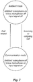
- Figure 7 is a state machine showing the two states or modes of the headset system 1 according to the invention.
- the ambient microphone In the uppermost ambient mode, the ambient microphone is switched on, while the voice microphone and the input signal are switched off.
- the left arrow indicates that the headset system switches from communication mode to ambient mode when a call is ended.
- the right arrow indicates that the headset system switches from ambient mode to communication mode, when there is an incoming or outgoing call.
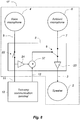
- FIG 8 is a schematic diagram of a headset system 1F in ambient mode.
- This headset system differs from the one shown in figures 5 and 6 by having a so-called "sidetone" feature. This means that the user can hear his own voice picked up by the voice microphone 4 during two-way communications.
- the voice signal 5 is via a voice signal amplifier 24 directed to an input of an adder 37 and thereby added to the input signal 12.
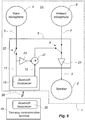
- FIG 9 is a schematic diagram of the headset system 1A in which the connection between the earphone 15 and the two-way communication device 10 is provided by a Bluetooth link 20.
- the headset 1A comprises a first Bluetooth transceiver 13 while the two-way communication device 10 comprises a second Bluetooth transceiver 26.
- the mode switch can be manual or automatic. Also, if automatic, the user may be able to override, so that he during a call temporary can listen to ambient sounds before returning to the call.
- the automatic switching can be obtained by a small relay, that detects when there is an input signal 12 of certain strength.
- headset system 19 microphone boom 2 speaker 20 Bluetooth link 3 speaker signal 21 user interface 4 voice microphone 22 voice signal switch 5 voice signal 23 speaker amplifier 6 ambient microphone 24 voice signal amplifier 7 ambient sound signal 25 headset cord 8 control circuit 26 headset buttons 9 mode switching circuit 27 headset base 10 two-way communication device 28 DECT link 11 output signal 29 computer with softphone 12 input signal 30 wire 13 headset Bluetooth transceiver 31 user 14 two-way communication terminal Bluetooth transceiver 32 end piece 33 headset 15 earphone 34 headset cradle 16 body worn headset housing 35 charging contacts 17 headband 36 headset 18 ear pad 37 adder
Description
- The invention relates to a communication headset system according to the preamble of
claim 1. - Headsets for two-way communication become more and more popular. They are used in different setups, e.g. plain corded headsets connected to desk top phones, corded headsets in call centers, wireless office headsets following the DECT standard, corded and wireless Bluetooth headsets used with mobile phones. In these years, "unified communication" (UC) becomes more prevalent. Unified communication is the integration of real-time communication services such as instant messaging, presence information, IP telephony, video conferencing, call control and speech recognition with non real-time communication services such as unified messaging (integrated voicemail, e-mail, SMS and fax). This means, that more people will use headsets more often and in longer periods during the day. One of the main advantages by using a headset is that the user's hands are free during conversation for other purposes such as typing, handling papers etc. Especially when using a wireless headset, the user can walk around the office or go to a quite room in order not to disturb colleagues during long phone calls.
- However, there is a disadvantage of wearing a headset. The earphone is more or less blocking out external sounds, which can be undesirably in certain situations.
-
US 2001/0046304 discloses a headset with selective acoustical isolation from the external environment. The earphone sound listened to may be attenuated temporarily in the event of a certain external sound captured by a microphone. The external sound is amplified and directed to the speaker in what is termed a "hearthrough mode".
WO 2007/085307 discloses an earphone with a through going channel, which can be in a closed state and an open state. In the open state, ambient sounds can pass through. The earphone may be configured to switch the channel to the closed state when speaking on the phone.
WO 2007/102047 discloses a headset with an ambient sound microphone. A processor combines ambient sound with audio from an electronic audio device.
WO 2008/051631 also discloses a headset with an ambient sound microphone. In normal use, the user hears a mix between audio from a connected device and the ambient sound. The ambient sound is switched off or disabled when a "predefined event" is detected. -
US 2003/0118197 discloses a headset with a voice microphone on a boom, an ambient sound microphone on the earphone and a transceiver attached to the headband of the headphones. The headset user can switch between different modes of operation. -
WO 2008/002266 discloses a headset with two earpieces and a throat microphone to record the wearer's voice signal. Each earpiece has a microphone to detect ambient sound. -
WO 2008/138349 discloses earphones with microphones to detect ambient sound. The user selects different listening or operation modes. -
US 2001/0046304 discloses a system to control what sound is relayed to loudspeakers in headsets, where the headset has microphones to detect ambient noise. As indicated above, the prior art disclose different solutions for avoiding the disadvantages of headsets blocking out ambient sounds, but there is still a need for a simple and reliable solution. - The invention provides a communication headset system for connecting to a two-way communication device, as described in
claim 1. With such a system, the user can simply switch between the ambient mode, in which he is not isolated from the ambient sounds, and the communication mode, in which he can concentrate on speak and hear sounds coming from the two-way communication device with minimum disturbance from the surroundings.
According to an embodiment, the control circuit is adapted to transmit an output signal comprising the voice signal to the two-way communication device in the communication mode.
Preferably, a user interface is provided for switching between the ambient mode and the communication mode. Thus, the user can select between the two modes.
According to a preferred embodiment, the control circuit is adapted to automatically enter the communication mode, when it receives an input signal from the two-way communication device. Thus, the user does not to have to manually select mode, when e.g. a phone calla is accepted or ended.
The invention is especially advantageous, if the headset system comprises a first earphone and a second earphone, as such a headset system blocks out ambient sound from both ears.
The first earphone and the second earphone may be interconnected by a headband or a neckband.
According to an embodiment, the communication headset system comprises a headset housing, which comprises the ambient microphone.
According to an embodiment, the headset housing may be separate from the earphones. - Thus, the headset housing can be a body worn housing. In this case, the ambient microphone can be arranged a far distance from the user's mouth thereby catching the ambient sounds without the user's own voice becoming too predominating.
- According to another embodiment, the headset housing is a headset base adapted to be placed on a surface, such as a desktop or a wall, during use. Also, in this case, the ambient microphone can be arranged at a suitable distance from the user's mouth.
- According to yet another embodiment, an earphone comprises the ambient microphone.
- In a specific embodiment, each of the first earphone and the second earphone comprises an ambient microphone. Such a configuration can be used for providing a spatial effect. Thus, the user's right ear hear ambient sound picked up by the ambient microphone on the right earphone while the user's left ear hear the ambient sound picked up by the ambient microphone on the left earphone.
- The voice microphone may be arranged on a microphone boom in order to bring it closer to the user's mouth during use.
- According to an embodiment, the control circuit is adapted to add the voice signal to the speaker signal in the communication mode. Hereby, the user can hear his own voice during two-way communications, and this feature is referred to as the "sidetone" effect.
- The ambient microphone is preferably omnidirectional.
- The invention is explained in detail below with reference to the drawing illustrating a preferred embodiment of the invention and in which
-
Fig. 1 is a view of a communication headset system according to the invention, -
Fig. 2 a view of a communication headset, -
Fig. 3 is a view a third embodiment of a communication headset, -
Fig. 4 is a view a communication headset, -
Fig. 5 is a schematic diagram in ambient mode, -
Fig. 6 is a schematic diagram in communication mode, -
Fig. 7 is a state machine showing the two states of the headset system according to the invention, -
Fig. 8 is a schematic diagram of a ambient mode, and -
Fig. 9 is a schematic view of the headset in ambient mode. -
Figure 1 discloses aheadset system 1A. This is based on a conventional Bluetooth headset, which is especially intended for use with Bluetooth enabled mobile phones. It comprises anearphone 15, which is arranged at theouter ear 25 of auser 31. In this embodiment, theearphone 15 is attached by inserting a non-visible earbud in the ear. However, other attachment devices, such as an ear hook, ear loop, a headband, could be used. A Bluetooth transceiver in theearphone 15 is wirelessly connected by aBluetooth link 20 to a Bluetooth transceiver in amobile phone 10. The earphone housing is elongate and points in the direction of the mouth of theuser 31. At the end of theearphone 15 closest to the mouth, theearphone 15 is provided with aconventional voice microphone 4 for picking up the user's voice during two-way communication via themobile phone 10. At the opposite end of theearphone 15, anambient microphone 6 is provided for picking up ambient sounds, when theuser 31 is not on a phone call. -
Figure 2 discloses a headset system 1B. Twoearphones wire 25 to a so-called body wornheadset housing 16. Avoice microphone 4 is provided as a "soap on the rope" between theearphones housing 16. Thehousing 16 comprises a Bluetooth transceiver, control circuit,headset buttons 26 and anambient microphone 6. The headset system 1B is wirelessly connected to amobile phone 10 via aBluetooth link 20. -
Figure 3 discloses aheadset system 1C. Thisheadset system 1C is designed for office use. It comprises awireless headset 33 and acorresponding headset base 27. Theheadset system 1C is following the DECT standard and theheadset 33 and theheadset base 27 each comprise a DECT transceiver, whereby they during use are interconnected by aDECT link 28. Theheadset 33 comprises aheadband 17 with anearphone 15 at one end and anend piece 32 at the other end. Amicrophone boom 19 extends from theearphone 15 in the direction of the user's mouth during use, and avoice microphone 4 is provided at the free end of themicrophone boom 19. Anambient microphone 6 is provided on theearphone 15. Theheadset base 27 is adapted to stand on a desktop and comprises aheadset cradle 34 with chargingcontacts 35 for receiving theheadset 33, when this is not in use. Theheadset base 27 furthermore comprises atouch display 21 as user interface. Theheadset base 27 is by means of acord 30 connected to adesktop computer 29 which is connected to the Internet and includes appropriate telephony software. -
Figure 4 discloses aheadset system 1D. Theheadset system 1D comprises acorded headset 36 with twoearphones headband 17. Eachearphone ear pad 18 for enhancing the user comfort and blocking out ambient sounds during two-way communication. Acord 30 extends from thefirst earphone 15A to a not-shown desktop phone. Also, amicrophone boom 19 with avoice microphone 4 at the free end extends from thefirst earphone 15A. The housing of thefirst earphone 15A comprises a firstambient microphone 6A and the housing of thesecond earphone 15B comprises a secondambient microphone 6B. During telephone conversations theambient microphones voice microphone 4. When the user is not on a call, thevoice microphone 4 is switched off while theambient microphones ambient microphone 6A is directed to the speaker of thefirst earphone 15A, and sound from the secondambient microphone 6B is directed to the speaker of thesecond earphone 15B. Thus, the user experiences a spatial effect, whereby he is able to hear form which direction ambient sounds are coming. -
Figure 5 is a diagram schematically showing parts of theheadset system 1E. Theheadset system 1E comprises avoice microphone 4, anambient microphone 6, aspeaker 2 and acontrol circuit 8. Thecontrol circuit 8 receives avoice signal 5 from thevoice microphone 4 and anambient sound signal 7 from theambient microphone 6. Aspeaker signal 3 is directed from thecontrol circuit 8 to thespeaker 2. Thecontrol circuit 8 is also connected to a two-way communication terminal 10, such as a desktop phone, mobile phone or soft phone. Thus, thecontrol circuit 8 sends anoutput signal 11 comprising thevoice signal 5 to the two-way communication terminal 10 and receives aninput signal 12 from the two-way communication terminal 10. Avoice signal switch 22 is provided to switch on and off the voice signal to/from theoutput signal 11. Amode switch 9 is provided for switching theheadset system 1E between an ambient mode in which thespeaker signal 3 comprises theambient sound signal 7 and not theinput signal 12 and a communication mode in which thespeaker signal 3 comprises theinput signal 12 and not theambient sound signal 7. Thus, in the ambient mode, the user can hear ambient sounds picked up by theambient microphone 6 only, and in the communication mode, the user can hear theinput signal 12 coming from the two-way communication terminal 10 only. The switching can be manual or automatic. When manual, the user can f. ex. press a button on the headset to change mode, and when automatic, the communication mode is automatically selected when there is aninput signal 12 from the two-way communication terminal 10. Aspeaker amplifier 23 is provided to amplify thespeaker signal 3 to an suitable level. Infigure 5 , theheadset system 1E is in the ambient mode. Thevoice signal switch 22 is operatively connected to themode switch 9, so that thevoice signal 5 is automatically switched off from theoutput signal 11, when theheadset system 1E is in the ambient mode. -
Figure 6 discloses theheadset system 1E in the communication mode.
Figure 7 is a state machine showing the two states or modes of theheadset system 1 according to the invention. In the uppermost ambient mode, the ambient microphone is switched on, while the voice microphone and the input signal are switched off. In the lowermost communication mode, the ambient microphone is switched off while the voice microphone and the input signal are switched on. The left arrow indicates that the headset system switches from communication mode to ambient mode when a call is ended. The right arrow indicates that the headset system switches from ambient mode to communication mode, when there is an incoming or outgoing call. -
Figure 8 is a schematic diagram of aheadset system 1F in ambient mode. This headset system differs from the one shown infigures 5 and6 by having a so-called "sidetone" feature. This means that the user can hear his own voice picked up by thevoice microphone 4 during two-way communications. Thevoice signal 5 is via avoice signal amplifier 24 directed to an input of anadder 37 and thereby added to theinput signal 12. -
Figure 9 is a schematic diagram of theheadset system 1A in which the connection between theearphone 15 and the two-way communication device 10 is provided by aBluetooth link 20. In order to obtain this, theheadset 1A comprises afirst Bluetooth transceiver 13 while the two-way communication device 10 comprises asecond Bluetooth transceiver 26.
The embodiments shown here are only examples of the invention. In all embodiments, the mode switch can be manual or automatic. Also, if automatic, the user may be able to override, so that he during a call temporary can listen to ambient sounds before returning to the call. The automatic switching can be obtained by a small relay, that detects when there is aninput signal 12 of certain strength.List of reference signs: 1 headset system 19 microphone boom 2 speaker 20 Bluetooth link 3 speaker signal 21 user interface 4 voice microphone 22 voice signal switch 5 voice signal 23 speaker amplifier 6 ambient microphone 24 voice signal amplifier 7 ambient sound signal 25 headset cord 8 control circuit 26 headset buttons 9 mode switching circuit 27 headset base 10 two- way communication device 28 DECT link 11 output signal 29 computer with softphone 12 input signal 30 wire 13 headset Bluetooth transceiver 31 user 14 two-way communication terminal Bluetooth transceiver 32 end piece 33 headset 15 earphone 34 headset cradle 16 body worn headset housing 35 charging contacts 17 headband 36 headset 18 ear pad 37 adder
Claims (16)
- A communication headset system (1) for connecting to a two-way communication device (10), said communication headset system (1) comprising
an earphone (15) with a speaker (2) for receiving a speaker signal (3) and converting it into speaker sound,
a voice microphone (4) for receiving a user's voice and converting it into a voice signal (5),
an ambient microphone (6), arranged at a distance from the voice microphone (4), for receiving ambient sound and converting it into an ambient sound signal (7),
a control circuit (8) for receiving the ambient sound signal (7) and an input signal (12) from the two-way communication device (10), and for transmitting the speaker signal (3) to the speaker (2),
wherein the control circuit (8) comprises a mode switching circuit (9) for switching the headset system between an ambient mode in which the speaker signal (3) comprises the ambient sound signal (7) and not the input signal (12) and a communication mode in which the speaker signal (3) comprises the input signal (12) and not the ambient sound signal (7),
characterised in that
the mode switching circuit (9) switches the voice microphone (4) off when switching from the communication mode to the ambient mode. - A communication headset system (1) according to claim 1, wherein the control circuit (8) is adapted to transmit an output signal (11) comprising the voice signal (5) to the two-way communication device (10) in the communication mode.
- A communication headset system (1) according to claim 1 or 2, wherein a user interface (21) is provided for switching between the ambient mode and the communication mode.
- A communication headset system (1) according to any of the claims 1-3, wherein the control circuit (8) is adapted to automatically enter the communication mode when it receives an input signal (12) from the two-way communication device (10).
- A communication headset system (1) according to any of the preceding claims, comprising a first earphone (15A) and a second earphone (16B).
- A communication headset system (1) according to claim 5, wherein the first earphone (15A) and the second earphone (16B) are interconnected by a headband (17) or a neckband.
- A communication headset system (1) according to any of the preceding claims, wherein the communication headset system (1) comprises a headset housing (15; 16; 27), which comprises the ambient microphone (6).
- A communication headset system (1) according to claim 7, wherein the headset housing (16; 27) is separate from the earphones (15A, 15B).
- A communication headset system (1) according to claim 8, wherein the headset housing is a body worn housing (16).
- A communication headset system (1) according to claim 8, wherein the headset housing is a headset base (27) adapted to be placed on a surface, such as a desktop or a wall, during use.
- A communication headset system (1) according to any of the claims 1-7, wherein an earphone (15) comprises the ambient microphone (6).
- A communication headset system (1) according to claim 5 and claim 11, wherein each of the first earphone (15A) and the second earphone (15B) comprises an ambient microphone (6).
- A communication headset system (1) according to any of the preceding claims, wherein the voice microphone (4) is arranged on a microphone boom (19).
- A communication headset system (1) according to any of the preceding claims, wherein the control circuit is (8) is adapted to add the voice signal (5) to the speaker signal (3) in the communication mode.
- A communication headset system (1) according to any of the preceding claims, wherein the ambient microphone or microphones (6) is/are omnidirectional.
- A communication headset system according to any of the preceding claims, wherein the mode switching circuit (9) further comprises a voice signal switch (22) operatively connected to the mode switching circuit (9) so that the voice signal (5) is automatically switched off from the output signal (11), when the headset system is in the ambient mode.
Priority Applications (4)
| Application Number | Priority Date | Filing Date | Title |
|---|---|---|---|
| EP10154525.9A EP2362678B1 (en) | 2010-02-24 | 2010-02-24 | A headset system with microphone for ambient sounds |
| US13/033,693 US20110206217A1 (en) | 2010-02-24 | 2011-02-24 | Headset system with microphone for ambient sounds |
| CN2011100459080A CN102164327A (en) | 2010-02-24 | 2011-02-24 | A headset system with microphone for ambient sounds |
| US14/315,986 US20140307868A1 (en) | 2010-02-24 | 2014-06-26 | Headset system with microphone for ambient sounds |
Applications Claiming Priority (1)
| Application Number | Priority Date | Filing Date | Title |
|---|---|---|---|
| EP10154525.9A EP2362678B1 (en) | 2010-02-24 | 2010-02-24 | A headset system with microphone for ambient sounds |
Publications (2)
| Publication Number | Publication Date |
|---|---|
| EP2362678A1 EP2362678A1 (en) | 2011-08-31 |
| EP2362678B1 true EP2362678B1 (en) | 2017-07-26 |
Family
ID=42289141
Family Applications (1)
| Application Number | Title | Priority Date | Filing Date |
|---|---|---|---|
| EP10154525.9A Active EP2362678B1 (en) | 2010-02-24 | 2010-02-24 | A headset system with microphone for ambient sounds |
Country Status (3)
| Country | Link |
|---|---|
| US (2) | US20110206217A1 (en) |
| EP (1) | EP2362678B1 (en) |
| CN (1) | CN102164327A (en) |
Families Citing this family (60)
| Publication number | Priority date | Publication date | Assignee | Title |
|---|---|---|---|---|
| US8611560B2 (en) | 2007-04-13 | 2013-12-17 | Navisense | Method and device for voice operated control |
| US8199942B2 (en) * | 2008-04-07 | 2012-06-12 | Sony Computer Entertainment Inc. | Targeted sound detection and generation for audio headset |
| US9129291B2 (en) | 2008-09-22 | 2015-09-08 | Personics Holdings, Llc | Personalized sound management and method |
| WO2013093565A1 (en) * | 2011-12-22 | 2013-06-27 | Nokia Corporation | Spatial audio processing apparatus |
| EP2645750A1 (en) | 2012-03-30 | 2013-10-02 | GN Store Nord A/S | A hearing device with an inertial measurement unit |
| EP2669634A1 (en) | 2012-05-30 | 2013-12-04 | GN Store Nord A/S | A personal navigation system with a hearing device |
| EP2685217A1 (en) | 2012-07-12 | 2014-01-15 | GN Store Nord A/S | A hearing device providing spoken information on the surroundings |
| EP2690407A1 (en) | 2012-07-23 | 2014-01-29 | GN Store Nord A/S | A hearing device providing spoken information on selected points of interest |
| US9055368B1 (en) * | 2012-08-17 | 2015-06-09 | The United States Of America As Represented By The Secretary Of The Navy | Sound identification and discernment device |
| US8878043B2 (en) * | 2012-09-10 | 2014-11-04 | uSOUNDit Partners, LLC | Systems, methods, and apparatus for music composition |
| EP2720001A1 (en) | 2012-10-15 | 2014-04-16 | GN Store Nord A/S | A navigation system with a hearing device |
| EP2725818A1 (en) | 2012-10-23 | 2014-04-30 | GN Store Nord A/S | A hearing device with a distance measurement unit |
| CN102963739B (en) * | 2012-11-02 | 2015-03-25 | 马彦民 | Counting monitoring method of bagged cement truck |
| SE537587C2 (en) * | 2012-11-28 | 2015-07-07 | Bo Franzén | Headset and ear unit |
| KR102091003B1 (en) * | 2012-12-10 | 2020-03-19 | 삼성전자 주식회사 | Method and apparatus for providing context aware service using speech recognition |
| US9208769B2 (en) | 2012-12-18 | 2015-12-08 | Apple Inc. | Hybrid adaptive headphone |
| US10043535B2 (en) * | 2013-01-15 | 2018-08-07 | Staton Techiya, Llc | Method and device for spectral expansion for an audio signal |
| US20140233753A1 (en) * | 2013-02-11 | 2014-08-21 | Matthew Waldman | Headphones with cloud integration |
| US9270244B2 (en) * | 2013-03-13 | 2016-02-23 | Personics Holdings, Llc | System and method to detect close voice sources and automatically enhance situation awareness |
| US8761431B1 (en) | 2013-08-15 | 2014-06-24 | Joelise, LLC | Adjustable headphones |
| US9392353B2 (en) * | 2013-10-18 | 2016-07-12 | Plantronics, Inc. | Headset interview mode |
| EP2942980A1 (en) | 2014-05-08 | 2015-11-11 | GN Store Nord A/S | Real-time control of an acoustic environment |
| EP3038421A1 (en) * | 2014-12-22 | 2016-06-29 | GN Netcom A/S | Method and apparatus for communication using a dect communications protocol |
| US9636260B2 (en) | 2015-01-06 | 2017-05-02 | Honeywell International Inc. | Custom microphones circuit, or listening circuit |
| GB2536310B (en) * | 2015-03-09 | 2017-11-15 | Cirrus Logic Int Semiconductor Ltd | Identification of modules on a bus |
| US9807491B2 (en) | 2015-04-03 | 2017-10-31 | Pinn, Inc. | Electronic device with wireless earbud |
| US10455066B2 (en) | 2015-04-03 | 2019-10-22 | Pinn, Inc. | Mobile system with wireless earbud |
| KR20170017475A (en) * | 2015-08-07 | 2017-02-15 | 엘지전자 주식회사 | Earphone, mobile terminal and method for controlling the same |
| US9584901B1 (en) * | 2015-09-07 | 2017-02-28 | Bose Corporation | Convertible headphone system |
| DK3550858T3 (en) * | 2015-12-30 | 2023-06-12 | Gn Hearing As | A HEAD PORTABLE HEARING AID |
| US9729957B1 (en) * | 2016-01-25 | 2017-08-08 | Cirrus Logic, Inc. | Dynamic frequency-dependent sidetone generation |
| CN107371081B (en) | 2016-02-03 | 2019-12-17 | 深圳市汇顶科技股份有限公司 | Earphone set |
| US9584896B1 (en) | 2016-02-09 | 2017-02-28 | Lethinal Kennedy | Ambient noise headphones |
| US9813800B2 (en) | 2016-03-11 | 2017-11-07 | Terry Stringer | Audio surveillance system |
| KR20170121545A (en) * | 2016-04-25 | 2017-11-02 | 해보라 주식회사 | Earset and the control method for the same |
| TWI639344B (en) * | 2016-09-05 | 2018-10-21 | 塞席爾商元鼎音訊股份有限公司 | Sound collection equipment having function of answering incoming calls and control method of sound collection |
| US10433095B2 (en) | 2016-11-13 | 2019-10-01 | EmbodyVR, Inc. | System and method to capture image of pinna and characterize human auditory anatomy using image of pinna |
| WO2018111894A1 (en) * | 2016-12-13 | 2018-06-21 | Onvocal, Inc. | Headset mode selection |
| EP3337186A1 (en) | 2016-12-16 | 2018-06-20 | GN Hearing A/S | Binaural hearing device system with a binaural impulse environment classifier |
| US10405081B2 (en) * | 2017-02-08 | 2019-09-03 | Bragi GmbH | Intelligent wireless headset system |
| US10074356B1 (en) | 2017-03-09 | 2018-09-11 | Plantronics, Inc. | Centralized control of multiple active noise cancellation devices |
| DE102017105767A1 (en) | 2017-03-17 | 2018-09-20 | Sennheiser Electronic Gmbh & Co. Kg | Earphones with separate microphones for binaural recordings and to telephone |
| DE102017207581A1 (en) * | 2017-05-05 | 2018-11-08 | Sivantos Pte. Ltd. | Hearing system and hearing device |
| CN107071683A (en) * | 2017-06-22 | 2017-08-18 | 歌尔股份有限公司 | Radio communication headset detection apparatus and method |
| US10405082B2 (en) | 2017-10-23 | 2019-09-03 | Staton Techiya, Llc | Automatic keyword pass-through system |
| EP3815067B1 (en) | 2018-06-27 | 2024-02-21 | Husqvarna Ab | Improved arboriculture safety system |
| US10951996B2 (en) | 2018-06-28 | 2021-03-16 | Gn Hearing A/S | Binaural hearing device system with binaural active occlusion cancellation |
| US10361673B1 (en) | 2018-07-24 | 2019-07-23 | Sony Interactive Entertainment Inc. | Ambient sound activated headphone |
| CN109348334B (en) * | 2018-10-26 | 2020-11-10 | 歌尔科技有限公司 | Wireless earphone and environment monitoring method and device thereof |
| WO2020131963A1 (en) * | 2018-12-21 | 2020-06-25 | Nura Holdings Pty Ltd | Modular ear-cup and ear-bud and power management of the modular ear-cup and ear-bud |
| CN111479180B (en) * | 2019-01-24 | 2022-04-29 | Oppo广东移动通信有限公司 | Pickup control method and related product |
| US11432086B2 (en) * | 2019-04-16 | 2022-08-30 | Biamp Systems, LLC | Centrally controlling communication at a venue |
| US10741164B1 (en) * | 2019-05-28 | 2020-08-11 | Bose Corporation | Multipurpose microphone in acoustic devices |
| DE102020114429A1 (en) | 2020-05-29 | 2021-12-02 | Rheinisch-Westfälische Technische Hochschule Aachen, Körperschaft des öffentlichen Rechts | METHOD, DEVICE, HEADPHONES AND COMPUTER PROGRAM FOR ACTIVE SUPPRESSION OF THE OCCLUSION EFFECT DURING THE REPLAY OF AUDIO SIGNALS |
| US11388498B1 (en) * | 2020-12-30 | 2022-07-12 | Gn Audio A/S | Binaural hearing device with monaural ambient mode |
| US11778408B2 (en) | 2021-01-26 | 2023-10-03 | EmbodyVR, Inc. | System and method to virtually mix and audition audio content for vehicles |
| US11573761B2 (en) * | 2021-06-03 | 2023-02-07 | Bose Corporation | Audio-based near field communication |
| US11700474B2 (en) * | 2021-06-24 | 2023-07-11 | New Audio LLC | Multi-microphone headset |
| USD1000416S1 (en) | 2021-06-24 | 2023-10-03 | New Audio LLC | Wireless headphones |
| CN114466278B (en) * | 2022-04-11 | 2022-08-16 | 北京荣耀终端有限公司 | Method for determining parameters corresponding to earphone mode, earphone, terminal and system |
Family Cites Families (12)
| Publication number | Priority date | Publication date | Assignee | Title |
|---|---|---|---|---|
| US6694034B2 (en) * | 2000-01-07 | 2004-02-17 | Etymotic Research, Inc. | Transmission detection and switch system for hearing improvement applications |
| US20010046304A1 (en) | 2000-04-24 | 2001-11-29 | Rast Rodger H. | System and method for selective control of acoustic isolation in headsets |
| US7062302B2 (en) * | 2000-05-12 | 2006-06-13 | Denso Corporation | Mobile terminal having power saving function variable with microphone usage conditions |
| JP4202640B2 (en) * | 2001-12-25 | 2008-12-24 | 株式会社東芝 | Short range wireless communication headset, communication system using the same, and acoustic processing method in short range wireless communication |
| US7881927B1 (en) * | 2003-09-26 | 2011-02-01 | Plantronics, Inc. | Adaptive sidetone and adaptive voice activity detect (VAD) threshold for speech processing |
| US8295505B2 (en) | 2006-01-30 | 2012-10-23 | Sony Ericsson Mobile Communications Ab | Earphone with controllable leakage of surrounding sound and device therefor |
| US7903826B2 (en) | 2006-03-08 | 2011-03-08 | Sony Ericsson Mobile Communications Ab | Headset with ambient sound |
| SE530137C2 (en) * | 2006-06-27 | 2008-03-11 | Bo Franzen | Headset with throat microphone in combination with an ear-tight soundproof ear speaker |
| US8208642B2 (en) * | 2006-07-10 | 2012-06-26 | Starkey Laboratories, Inc. | Method and apparatus for a binaural hearing assistance system using monaural audio signals |
| US7986802B2 (en) | 2006-10-25 | 2011-07-26 | Sony Ericsson Mobile Communications Ab | Portable electronic device and personal hands-free accessory with audio disable |
| WO2008138349A2 (en) * | 2007-05-10 | 2008-11-20 | Microsound A/S | Enhanced management of sound provided via headphones |
| JP4968373B2 (en) * | 2010-08-02 | 2012-07-04 | ダイキン工業株式会社 | Air conditioner |
-
2010
- 2010-02-24 EP EP10154525.9A patent/EP2362678B1/en active Active
-
2011
- 2011-02-24 US US13/033,693 patent/US20110206217A1/en not_active Abandoned
- 2011-02-24 CN CN2011100459080A patent/CN102164327A/en active Pending
-
2014
- 2014-06-26 US US14/315,986 patent/US20140307868A1/en not_active Abandoned
Non-Patent Citations (1)
| Title |
|---|
| None * |
Also Published As
| Publication number | Publication date |
|---|---|
| US20140307868A1 (en) | 2014-10-16 |
| CN102164327A (en) | 2011-08-24 |
| US20110206217A1 (en) | 2011-08-25 |
| EP2362678A1 (en) | 2011-08-31 |
Similar Documents
| Publication | Publication Date | Title |
|---|---|---|
| EP2362678B1 (en) | A headset system with microphone for ambient sounds | |
| JP5155296B2 (en) | Headset audio accessories | |
| US9036833B2 (en) | External ear canal voice detection | |
| US7689248B2 (en) | Listening assistance function in phone terminals | |
| US8761841B2 (en) | Personal conferencing device | |
| US9301037B1 (en) | Wireless phone accessory | |
| CN201197140Y (en) | Wireless playing headphone | |
| JP2010283873A (en) | Microphone techniques | |
| JP2015510304A (en) | Ultra compact headset | |
| EP4105925A1 (en) | Headset with automatic noise reduction mode switching | |
| KR101092957B1 (en) | Microphone | |
| TWM563122U (en) | Hearing assistance device | |
| EP3072314B1 (en) | A method of operating a hearing system for conducting telephone calls and a corresponding hearing system | |
| JP2007259276A (en) | Wireless communication telephone conversation unit | |
| US20110135108A1 (en) | Dual-functional earphone | |
| KR101820369B1 (en) | Bluetooth Communication Method Of Smartphone To A Headset | |
| KR101109748B1 (en) | Microphone | |
| CN215300880U (en) | Hearing aid earphone | |
| KR102502385B1 (en) | Bluetooth head phone with hearing aid | |
| KR101022312B1 (en) | Earmicrophone | |
| KR100494981B1 (en) | Send-receive device for visual communication | |
| RU53469U1 (en) | I / O AUDIO DEVICE FOR PERSONAL COMPUTER | |
| JP2008011300A (en) | Radio hearing aid system | |
| JPH01279659A (en) | Telephone set | |
| JP2005223869A (en) | Method of arranging microphone, speaker and switch comprising a hands-free device for cellular phone, and sound volume of speaker |
Legal Events
| Date | Code | Title | Description |
|---|---|---|---|
| PUAI | Public reference made under article 153(3) epc to a published international application that has entered the european phase |
Free format text: ORIGINAL CODE: 0009012 |
|
| AK | Designated contracting states |
Kind code of ref document: A1 Designated state(s): AT BE BG CH CY CZ DE DK EE ES FI FR GB GR HR HU IE IS IT LI LT LU LV MC MK MT NL NO PL PT RO SE SI SK SM TR |
|
| AX | Request for extension of the european patent |
Extension state: AL BA RS |
|
| 17P | Request for examination filed |
Effective date: 20120229 |
|
| 17Q | First examination report despatched |
Effective date: 20121207 |
|
| GRAP | Despatch of communication of intention to grant a patent |
Free format text: ORIGINAL CODE: EPIDOSNIGR1 |
|
| RIC1 | Information provided on ipc code assigned before grant |
Ipc: H04M 1/05 20060101ALI20170216BHEP Ipc: H04R 5/033 20060101ALN20170216BHEP Ipc: H04B 1/38 20150101ALI20170216BHEP Ipc: H04R 5/027 20060101ALI20170216BHEP Ipc: H04M 1/60 20060101ALI20170216BHEP Ipc: H04R 1/10 20060101AFI20170216BHEP |
|
| INTG | Intention to grant announced |
Effective date: 20170301 |
|
| GRAS | Grant fee paid |
Free format text: ORIGINAL CODE: EPIDOSNIGR3 |
|
| GRAA | (expected) grant |
Free format text: ORIGINAL CODE: 0009210 |
|
| AK | Designated contracting states |
Kind code of ref document: B1 Designated state(s): AT BE BG CH CY CZ DE DK EE ES FI FR GB GR HR HU IE IS IT LI LT LU LV MC MK MT NL NO PL PT RO SE SI SK SM TR |
|
| AX | Request for extension of the european patent |
Extension state: AL BA RS |
|
| RAP1 | Party data changed (applicant data changed or rights of an application transferred) |
Owner name: GN AUDIO A/S |
|
| REG | Reference to a national code |
Ref country code: GB Ref legal event code: FG4D |
|
| REG | Reference to a national code |
Ref country code: CH Ref legal event code: EP |
|
| REG | Reference to a national code |
Ref country code: AT Ref legal event code: REF Ref document number: 913295 Country of ref document: AT Kind code of ref document: T Effective date: 20170815 |
|
| REG | Reference to a national code |
Ref country code: IE Ref legal event code: FG4D |
|
| REG | Reference to a national code |
Ref country code: DE Ref legal event code: R096 Ref document number: 602010043830 Country of ref document: DE |
|
| REG | Reference to a national code |
Ref country code: NL Ref legal event code: MP Effective date: 20170726 |
|
| REG | Reference to a national code |
Ref country code: LT Ref legal event code: MG4D |
|
| REG | Reference to a national code |
Ref country code: AT Ref legal event code: MK05 Ref document number: 913295 Country of ref document: AT Kind code of ref document: T Effective date: 20170726 |
|
| PG25 | Lapsed in a contracting state [announced via postgrant information from national office to epo] |
Ref country code: SE Free format text: LAPSE BECAUSE OF FAILURE TO SUBMIT A TRANSLATION OF THE DESCRIPTION OR TO PAY THE FEE WITHIN THE PRESCRIBED TIME-LIMIT Effective date: 20170726 Ref country code: NO Free format text: LAPSE BECAUSE OF FAILURE TO SUBMIT A TRANSLATION OF THE DESCRIPTION OR TO PAY THE FEE WITHIN THE PRESCRIBED TIME-LIMIT Effective date: 20171026 Ref country code: AT Free format text: LAPSE BECAUSE OF FAILURE TO SUBMIT A TRANSLATION OF THE DESCRIPTION OR TO PAY THE FEE WITHIN THE PRESCRIBED TIME-LIMIT Effective date: 20170726 Ref country code: HR Free format text: LAPSE BECAUSE OF FAILURE TO SUBMIT A TRANSLATION OF THE DESCRIPTION OR TO PAY THE FEE WITHIN THE PRESCRIBED TIME-LIMIT Effective date: 20170726 Ref country code: LT Free format text: LAPSE BECAUSE OF FAILURE TO SUBMIT A TRANSLATION OF THE DESCRIPTION OR TO PAY THE FEE WITHIN THE PRESCRIBED TIME-LIMIT Effective date: 20170726 Ref country code: NL Free format text: LAPSE BECAUSE OF FAILURE TO SUBMIT A TRANSLATION OF THE DESCRIPTION OR TO PAY THE FEE WITHIN THE PRESCRIBED TIME-LIMIT Effective date: 20170726 Ref country code: FI Free format text: LAPSE BECAUSE OF FAILURE TO SUBMIT A TRANSLATION OF THE DESCRIPTION OR TO PAY THE FEE WITHIN THE PRESCRIBED TIME-LIMIT Effective date: 20170726 |
|
| REG | Reference to a national code |
Ref country code: FR Ref legal event code: PLFP Year of fee payment: 9 |
|
| PG25 | Lapsed in a contracting state [announced via postgrant information from national office to epo] |
Ref country code: IS Free format text: LAPSE BECAUSE OF FAILURE TO SUBMIT A TRANSLATION OF THE DESCRIPTION OR TO PAY THE FEE WITHIN THE PRESCRIBED TIME-LIMIT Effective date: 20171126 Ref country code: GR Free format text: LAPSE BECAUSE OF FAILURE TO SUBMIT A TRANSLATION OF THE DESCRIPTION OR TO PAY THE FEE WITHIN THE PRESCRIBED TIME-LIMIT Effective date: 20171027 Ref country code: ES Free format text: LAPSE BECAUSE OF FAILURE TO SUBMIT A TRANSLATION OF THE DESCRIPTION OR TO PAY THE FEE WITHIN THE PRESCRIBED TIME-LIMIT Effective date: 20170726 Ref country code: PL Free format text: LAPSE BECAUSE OF FAILURE TO SUBMIT A TRANSLATION OF THE DESCRIPTION OR TO PAY THE FEE WITHIN THE PRESCRIBED TIME-LIMIT Effective date: 20170726 Ref country code: LV Free format text: LAPSE BECAUSE OF FAILURE TO SUBMIT A TRANSLATION OF THE DESCRIPTION OR TO PAY THE FEE WITHIN THE PRESCRIBED TIME-LIMIT Effective date: 20170726 Ref country code: BG Free format text: LAPSE BECAUSE OF FAILURE TO SUBMIT A TRANSLATION OF THE DESCRIPTION OR TO PAY THE FEE WITHIN THE PRESCRIBED TIME-LIMIT Effective date: 20171026 |
|
| PG25 | Lapsed in a contracting state [announced via postgrant information from national office to epo] |
Ref country code: CZ Free format text: LAPSE BECAUSE OF FAILURE TO SUBMIT A TRANSLATION OF THE DESCRIPTION OR TO PAY THE FEE WITHIN THE PRESCRIBED TIME-LIMIT Effective date: 20170726 Ref country code: RO Free format text: LAPSE BECAUSE OF FAILURE TO SUBMIT A TRANSLATION OF THE DESCRIPTION OR TO PAY THE FEE WITHIN THE PRESCRIBED TIME-LIMIT Effective date: 20170726 Ref country code: DK Free format text: LAPSE BECAUSE OF FAILURE TO SUBMIT A TRANSLATION OF THE DESCRIPTION OR TO PAY THE FEE WITHIN THE PRESCRIBED TIME-LIMIT Effective date: 20170726 |
|
| REG | Reference to a national code |
Ref country code: DE Ref legal event code: R097 Ref document number: 602010043830 Country of ref document: DE |
|
| PG25 | Lapsed in a contracting state [announced via postgrant information from national office to epo] |
Ref country code: IT Free format text: LAPSE BECAUSE OF FAILURE TO SUBMIT A TRANSLATION OF THE DESCRIPTION OR TO PAY THE FEE WITHIN THE PRESCRIBED TIME-LIMIT Effective date: 20170726 Ref country code: SK Free format text: LAPSE BECAUSE OF FAILURE TO SUBMIT A TRANSLATION OF THE DESCRIPTION OR TO PAY THE FEE WITHIN THE PRESCRIBED TIME-LIMIT Effective date: 20170726 Ref country code: SM Free format text: LAPSE BECAUSE OF FAILURE TO SUBMIT A TRANSLATION OF THE DESCRIPTION OR TO PAY THE FEE WITHIN THE PRESCRIBED TIME-LIMIT Effective date: 20170726 Ref country code: EE Free format text: LAPSE BECAUSE OF FAILURE TO SUBMIT A TRANSLATION OF THE DESCRIPTION OR TO PAY THE FEE WITHIN THE PRESCRIBED TIME-LIMIT Effective date: 20170726 |
|
| PLBE | No opposition filed within time limit |
Free format text: ORIGINAL CODE: 0009261 |
|
| STAA | Information on the status of an ep patent application or granted ep patent |
Free format text: STATUS: NO OPPOSITION FILED WITHIN TIME LIMIT |
|
| 26N | No opposition filed |
Effective date: 20180430 |
|
| PG25 | Lapsed in a contracting state [announced via postgrant information from national office to epo] |
Ref country code: SI Free format text: LAPSE BECAUSE OF FAILURE TO SUBMIT A TRANSLATION OF THE DESCRIPTION OR TO PAY THE FEE WITHIN THE PRESCRIBED TIME-LIMIT Effective date: 20170726 |
|
| REG | Reference to a national code |
Ref country code: CH Ref legal event code: PL |
|
| PG25 | Lapsed in a contracting state [announced via postgrant information from national office to epo] |
Ref country code: MC Free format text: LAPSE BECAUSE OF FAILURE TO SUBMIT A TRANSLATION OF THE DESCRIPTION OR TO PAY THE FEE WITHIN THE PRESCRIBED TIME-LIMIT Effective date: 20170726 |
|
| REG | Reference to a national code |
Ref country code: IE Ref legal event code: MM4A |
|
| REG | Reference to a national code |
Ref country code: BE Ref legal event code: MM Effective date: 20180228 |
|
| PG25 | Lapsed in a contracting state [announced via postgrant information from national office to epo] |
Ref country code: LU Free format text: LAPSE BECAUSE OF NON-PAYMENT OF DUE FEES Effective date: 20180224 Ref country code: CH Free format text: LAPSE BECAUSE OF NON-PAYMENT OF DUE FEES Effective date: 20180228 Ref country code: LI Free format text: LAPSE BECAUSE OF NON-PAYMENT OF DUE FEES Effective date: 20180228 |
|
| PG25 | Lapsed in a contracting state [announced via postgrant information from national office to epo] |
Ref country code: IE Free format text: LAPSE BECAUSE OF NON-PAYMENT OF DUE FEES Effective date: 20180224 |
|
| PG25 | Lapsed in a contracting state [announced via postgrant information from national office to epo] |
Ref country code: BE Free format text: LAPSE BECAUSE OF NON-PAYMENT OF DUE FEES Effective date: 20180228 |
|
| PG25 | Lapsed in a contracting state [announced via postgrant information from national office to epo] |
Ref country code: MT Free format text: LAPSE BECAUSE OF NON-PAYMENT OF DUE FEES Effective date: 20180224 |
|
| PG25 | Lapsed in a contracting state [announced via postgrant information from national office to epo] |
Ref country code: TR Free format text: LAPSE BECAUSE OF FAILURE TO SUBMIT A TRANSLATION OF THE DESCRIPTION OR TO PAY THE FEE WITHIN THE PRESCRIBED TIME-LIMIT Effective date: 20170726 |
|
| PG25 | Lapsed in a contracting state [announced via postgrant information from national office to epo] |
Ref country code: PT Free format text: LAPSE BECAUSE OF FAILURE TO SUBMIT A TRANSLATION OF THE DESCRIPTION OR TO PAY THE FEE WITHIN THE PRESCRIBED TIME-LIMIT Effective date: 20170726 Ref country code: HU Free format text: LAPSE BECAUSE OF FAILURE TO SUBMIT A TRANSLATION OF THE DESCRIPTION OR TO PAY THE FEE WITHIN THE PRESCRIBED TIME-LIMIT; INVALID AB INITIO Effective date: 20100224 |
|
| PG25 | Lapsed in a contracting state [announced via postgrant information from national office to epo] |
Ref country code: MK Free format text: LAPSE BECAUSE OF NON-PAYMENT OF DUE FEES Effective date: 20170726 Ref country code: CY Free format text: LAPSE BECAUSE OF FAILURE TO SUBMIT A TRANSLATION OF THE DESCRIPTION OR TO PAY THE FEE WITHIN THE PRESCRIBED TIME-LIMIT Effective date: 20170726 |
|
| PGFP | Annual fee paid to national office [announced via postgrant information from national office to epo] |
Ref country code: FR Payment date: 20230215 Year of fee payment: 14 |
|
| PGFP | Annual fee paid to national office [announced via postgrant information from national office to epo] |
Ref country code: GB Payment date: 20230216 Year of fee payment: 14 Ref country code: DE Payment date: 20230217 Year of fee payment: 14 |
|
| P01 | Opt-out of the competence of the unified patent court (upc) registered |
Effective date: 20230522 |