EP2358302B1 - Stents and stent grafts - Google Patents
Stents and stent grafts Download PDFInfo
- Publication number
- EP2358302B1 EP2358302B1 EP09775486A EP09775486A EP2358302B1 EP 2358302 B1 EP2358302 B1 EP 2358302B1 EP 09775486 A EP09775486 A EP 09775486A EP 09775486 A EP09775486 A EP 09775486A EP 2358302 B1 EP2358302 B1 EP 2358302B1
- Authority
- EP
- European Patent Office
- Prior art keywords
- stent
- conformance
- proximal
- graft
- strut
- Prior art date
- Legal status (The legal status is an assumption and is not a legal conclusion. Google has not performed a legal analysis and makes no representation as to the accuracy of the status listed.)
- Active
Links
- 239000000463 material Substances 0.000 claims abstract description 64
- 238000000034 method Methods 0.000 claims description 12
- 208000001750 Endoleak Diseases 0.000 abstract description 5
- 230000017531 blood circulation Effects 0.000 description 6
- 210000002376 aorta thoracic Anatomy 0.000 description 5
- 229910001000 nickel titanium Inorganic materials 0.000 description 4
- 210000004369 blood Anatomy 0.000 description 3
- 239000008280 blood Substances 0.000 description 3
- HLXZNVUGXRDIFK-UHFFFAOYSA-N nickel titanium Chemical compound [Ti].[Ti].[Ti].[Ti].[Ti].[Ti].[Ti].[Ti].[Ti].[Ti].[Ti].[Ni].[Ni].[Ni].[Ni].[Ni].[Ni].[Ni].[Ni].[Ni].[Ni].[Ni].[Ni].[Ni].[Ni] HLXZNVUGXRDIFK-UHFFFAOYSA-N 0.000 description 3
- 229910001285 shape-memory alloy Inorganic materials 0.000 description 3
- 206010002329 Aneurysm Diseases 0.000 description 2
- 229910045601 alloy Inorganic materials 0.000 description 2
- 239000000956 alloy Substances 0.000 description 2
- 238000003698 laser cutting Methods 0.000 description 2
- 229910052751 metal Inorganic materials 0.000 description 2
- 239000002184 metal Substances 0.000 description 2
- 150000002739 metals Chemical class 0.000 description 2
- BASFCYQUMIYNBI-UHFFFAOYSA-N platinum Chemical compound [Pt] BASFCYQUMIYNBI-UHFFFAOYSA-N 0.000 description 2
- 229910000684 Cobalt-chrome Inorganic materials 0.000 description 1
- 206010064396 Stent-graft endoleak Diseases 0.000 description 1
- RTAQQCXQSZGOHL-UHFFFAOYSA-N Titanium Chemical compound [Ti] RTAQQCXQSZGOHL-UHFFFAOYSA-N 0.000 description 1
- 208000002223 abdominal aortic aneurysm Diseases 0.000 description 1
- 230000001154 acute effect Effects 0.000 description 1
- 230000002411 adverse Effects 0.000 description 1
- 238000002399 angioplasty Methods 0.000 description 1
- 210000000709 aorta Anatomy 0.000 description 1
- 208000007474 aortic aneurysm Diseases 0.000 description 1
- 238000003486 chemical etching Methods 0.000 description 1
- 239000010952 cobalt-chrome Substances 0.000 description 1
- 230000006835 compression Effects 0.000 description 1
- 238000007906 compression Methods 0.000 description 1
- 230000000694 effects Effects 0.000 description 1
- 239000012530 fluid Substances 0.000 description 1
- 238000002594 fluoroscopy Methods 0.000 description 1
- PCHJSUWPFVWCPO-UHFFFAOYSA-N gold Chemical compound [Au] PCHJSUWPFVWCPO-UHFFFAOYSA-N 0.000 description 1
- 229910052737 gold Inorganic materials 0.000 description 1
- 239000010931 gold Substances 0.000 description 1
- 238000003384 imaging method Methods 0.000 description 1
- 230000001939 inductive effect Effects 0.000 description 1
- 239000007769 metal material Substances 0.000 description 1
- 229910052697 platinum Inorganic materials 0.000 description 1
- 229920000642 polymer Polymers 0.000 description 1
- 229910000679 solder Inorganic materials 0.000 description 1
- 239000010935 stainless steel Substances 0.000 description 1
- 229910001220 stainless steel Inorganic materials 0.000 description 1
- 229910052715 tantalum Inorganic materials 0.000 description 1
- GUVRBAGPIYLISA-UHFFFAOYSA-N tantalum atom Chemical compound [Ta] GUVRBAGPIYLISA-UHFFFAOYSA-N 0.000 description 1
- 229920001169 thermoplastic Polymers 0.000 description 1
- 239000004416 thermosoftening plastic Substances 0.000 description 1
- 239000010936 titanium Substances 0.000 description 1
- 229910052719 titanium Inorganic materials 0.000 description 1
Images


Classifications
-
- A—HUMAN NECESSITIES
- A61—MEDICAL OR VETERINARY SCIENCE; HYGIENE
- A61F—FILTERS IMPLANTABLE INTO BLOOD VESSELS; PROSTHESES; DEVICES PROVIDING PATENCY TO, OR PREVENTING COLLAPSING OF, TUBULAR STRUCTURES OF THE BODY, e.g. STENTS; ORTHOPAEDIC, NURSING OR CONTRACEPTIVE DEVICES; FOMENTATION; TREATMENT OR PROTECTION OF EYES OR EARS; BANDAGES, DRESSINGS OR ABSORBENT PADS; FIRST-AID KITS
- A61F2/00—Filters implantable into blood vessels; Prostheses, i.e. artificial substitutes or replacements for parts of the body; Appliances for connecting them with the body; Devices providing patency to, or preventing collapsing of, tubular structures of the body, e.g. stents
- A61F2/82—Devices providing patency to, or preventing collapsing of, tubular structures of the body, e.g. stents
- A61F2/86—Stents in a form characterised by the wire-like elements; Stents in the form characterised by a net-like or mesh-like structure
- A61F2/90—Stents in a form characterised by the wire-like elements; Stents in the form characterised by a net-like or mesh-like structure characterised by a net-like or mesh-like structure
- A61F2/91—Stents in a form characterised by the wire-like elements; Stents in the form characterised by a net-like or mesh-like structure characterised by a net-like or mesh-like structure made from perforated sheet material or tubes, e.g. perforated by laser cuts or etched holes
-
- A—HUMAN NECESSITIES
- A61—MEDICAL OR VETERINARY SCIENCE; HYGIENE
- A61F—FILTERS IMPLANTABLE INTO BLOOD VESSELS; PROSTHESES; DEVICES PROVIDING PATENCY TO, OR PREVENTING COLLAPSING OF, TUBULAR STRUCTURES OF THE BODY, e.g. STENTS; ORTHOPAEDIC, NURSING OR CONTRACEPTIVE DEVICES; FOMENTATION; TREATMENT OR PROTECTION OF EYES OR EARS; BANDAGES, DRESSINGS OR ABSORBENT PADS; FIRST-AID KITS
- A61F2/00—Filters implantable into blood vessels; Prostheses, i.e. artificial substitutes or replacements for parts of the body; Appliances for connecting them with the body; Devices providing patency to, or preventing collapsing of, tubular structures of the body, e.g. stents
- A61F2/02—Prostheses implantable into the body
- A61F2/04—Hollow or tubular parts of organs, e.g. bladders, tracheae, bronchi or bile ducts
- A61F2/06—Blood vessels
- A61F2/07—Stent-grafts
-
- A—HUMAN NECESSITIES
- A61—MEDICAL OR VETERINARY SCIENCE; HYGIENE
- A61F—FILTERS IMPLANTABLE INTO BLOOD VESSELS; PROSTHESES; DEVICES PROVIDING PATENCY TO, OR PREVENTING COLLAPSING OF, TUBULAR STRUCTURES OF THE BODY, e.g. STENTS; ORTHOPAEDIC, NURSING OR CONTRACEPTIVE DEVICES; FOMENTATION; TREATMENT OR PROTECTION OF EYES OR EARS; BANDAGES, DRESSINGS OR ABSORBENT PADS; FIRST-AID KITS
- A61F2/00—Filters implantable into blood vessels; Prostheses, i.e. artificial substitutes or replacements for parts of the body; Appliances for connecting them with the body; Devices providing patency to, or preventing collapsing of, tubular structures of the body, e.g. stents
- A61F2/82—Devices providing patency to, or preventing collapsing of, tubular structures of the body, e.g. stents
- A61F2/86—Stents in a form characterised by the wire-like elements; Stents in the form characterised by a net-like or mesh-like structure
- A61F2/90—Stents in a form characterised by the wire-like elements; Stents in the form characterised by a net-like or mesh-like structure characterised by a net-like or mesh-like structure
- A61F2/91—Stents in a form characterised by the wire-like elements; Stents in the form characterised by a net-like or mesh-like structure characterised by a net-like or mesh-like structure made from perforated sheet material or tubes, e.g. perforated by laser cuts or etched holes
- A61F2/915—Stents in a form characterised by the wire-like elements; Stents in the form characterised by a net-like or mesh-like structure characterised by a net-like or mesh-like structure made from perforated sheet material or tubes, e.g. perforated by laser cuts or etched holes with bands having a meander structure, adjacent bands being connected to each other
-
- A—HUMAN NECESSITIES
- A61—MEDICAL OR VETERINARY SCIENCE; HYGIENE
- A61F—FILTERS IMPLANTABLE INTO BLOOD VESSELS; PROSTHESES; DEVICES PROVIDING PATENCY TO, OR PREVENTING COLLAPSING OF, TUBULAR STRUCTURES OF THE BODY, e.g. STENTS; ORTHOPAEDIC, NURSING OR CONTRACEPTIVE DEVICES; FOMENTATION; TREATMENT OR PROTECTION OF EYES OR EARS; BANDAGES, DRESSINGS OR ABSORBENT PADS; FIRST-AID KITS
- A61F2/00—Filters implantable into blood vessels; Prostheses, i.e. artificial substitutes or replacements for parts of the body; Appliances for connecting them with the body; Devices providing patency to, or preventing collapsing of, tubular structures of the body, e.g. stents
- A61F2/82—Devices providing patency to, or preventing collapsing of, tubular structures of the body, e.g. stents
- A61F2/848—Devices providing patency to, or preventing collapsing of, tubular structures of the body, e.g. stents having means for fixation to the vessel wall, e.g. barbs
-
- A—HUMAN NECESSITIES
- A61—MEDICAL OR VETERINARY SCIENCE; HYGIENE
- A61F—FILTERS IMPLANTABLE INTO BLOOD VESSELS; PROSTHESES; DEVICES PROVIDING PATENCY TO, OR PREVENTING COLLAPSING OF, TUBULAR STRUCTURES OF THE BODY, e.g. STENTS; ORTHOPAEDIC, NURSING OR CONTRACEPTIVE DEVICES; FOMENTATION; TREATMENT OR PROTECTION OF EYES OR EARS; BANDAGES, DRESSINGS OR ABSORBENT PADS; FIRST-AID KITS
- A61F2/00—Filters implantable into blood vessels; Prostheses, i.e. artificial substitutes or replacements for parts of the body; Appliances for connecting them with the body; Devices providing patency to, or preventing collapsing of, tubular structures of the body, e.g. stents
- A61F2/82—Devices providing patency to, or preventing collapsing of, tubular structures of the body, e.g. stents
- A61F2/86—Stents in a form characterised by the wire-like elements; Stents in the form characterised by a net-like or mesh-like structure
- A61F2/89—Stents in a form characterised by the wire-like elements; Stents in the form characterised by a net-like or mesh-like structure the wire-like elements comprising two or more adjacent rings flexibly connected by separate members
-
- A—HUMAN NECESSITIES
- A61—MEDICAL OR VETERINARY SCIENCE; HYGIENE
- A61F—FILTERS IMPLANTABLE INTO BLOOD VESSELS; PROSTHESES; DEVICES PROVIDING PATENCY TO, OR PREVENTING COLLAPSING OF, TUBULAR STRUCTURES OF THE BODY, e.g. STENTS; ORTHOPAEDIC, NURSING OR CONTRACEPTIVE DEVICES; FOMENTATION; TREATMENT OR PROTECTION OF EYES OR EARS; BANDAGES, DRESSINGS OR ABSORBENT PADS; FIRST-AID KITS
- A61F2/00—Filters implantable into blood vessels; Prostheses, i.e. artificial substitutes or replacements for parts of the body; Appliances for connecting them with the body; Devices providing patency to, or preventing collapsing of, tubular structures of the body, e.g. stents
- A61F2/02—Prostheses implantable into the body
- A61F2/04—Hollow or tubular parts of organs, e.g. bladders, tracheae, bronchi or bile ducts
- A61F2/06—Blood vessels
- A61F2/07—Stent-grafts
- A61F2002/075—Stent-grafts the stent being loosely attached to the graft material, e.g. by stitching
-
- A—HUMAN NECESSITIES
- A61—MEDICAL OR VETERINARY SCIENCE; HYGIENE
- A61F—FILTERS IMPLANTABLE INTO BLOOD VESSELS; PROSTHESES; DEVICES PROVIDING PATENCY TO, OR PREVENTING COLLAPSING OF, TUBULAR STRUCTURES OF THE BODY, e.g. STENTS; ORTHOPAEDIC, NURSING OR CONTRACEPTIVE DEVICES; FOMENTATION; TREATMENT OR PROTECTION OF EYES OR EARS; BANDAGES, DRESSINGS OR ABSORBENT PADS; FIRST-AID KITS
- A61F2/00—Filters implantable into blood vessels; Prostheses, i.e. artificial substitutes or replacements for parts of the body; Appliances for connecting them with the body; Devices providing patency to, or preventing collapsing of, tubular structures of the body, e.g. stents
- A61F2/82—Devices providing patency to, or preventing collapsing of, tubular structures of the body, e.g. stents
- A61F2/848—Devices providing patency to, or preventing collapsing of, tubular structures of the body, e.g. stents having means for fixation to the vessel wall, e.g. barbs
- A61F2002/8483—Barbs
-
- A—HUMAN NECESSITIES
- A61—MEDICAL OR VETERINARY SCIENCE; HYGIENE
- A61F—FILTERS IMPLANTABLE INTO BLOOD VESSELS; PROSTHESES; DEVICES PROVIDING PATENCY TO, OR PREVENTING COLLAPSING OF, TUBULAR STRUCTURES OF THE BODY, e.g. STENTS; ORTHOPAEDIC, NURSING OR CONTRACEPTIVE DEVICES; FOMENTATION; TREATMENT OR PROTECTION OF EYES OR EARS; BANDAGES, DRESSINGS OR ABSORBENT PADS; FIRST-AID KITS
- A61F2/00—Filters implantable into blood vessels; Prostheses, i.e. artificial substitutes or replacements for parts of the body; Appliances for connecting them with the body; Devices providing patency to, or preventing collapsing of, tubular structures of the body, e.g. stents
- A61F2/82—Devices providing patency to, or preventing collapsing of, tubular structures of the body, e.g. stents
- A61F2/848—Devices providing patency to, or preventing collapsing of, tubular structures of the body, e.g. stents having means for fixation to the vessel wall, e.g. barbs
- A61F2002/8486—Devices providing patency to, or preventing collapsing of, tubular structures of the body, e.g. stents having means for fixation to the vessel wall, e.g. barbs provided on at least one of the ends
-
- A—HUMAN NECESSITIES
- A61—MEDICAL OR VETERINARY SCIENCE; HYGIENE
- A61F—FILTERS IMPLANTABLE INTO BLOOD VESSELS; PROSTHESES; DEVICES PROVIDING PATENCY TO, OR PREVENTING COLLAPSING OF, TUBULAR STRUCTURES OF THE BODY, e.g. STENTS; ORTHOPAEDIC, NURSING OR CONTRACEPTIVE DEVICES; FOMENTATION; TREATMENT OR PROTECTION OF EYES OR EARS; BANDAGES, DRESSINGS OR ABSORBENT PADS; FIRST-AID KITS
- A61F2/00—Filters implantable into blood vessels; Prostheses, i.e. artificial substitutes or replacements for parts of the body; Appliances for connecting them with the body; Devices providing patency to, or preventing collapsing of, tubular structures of the body, e.g. stents
- A61F2/82—Devices providing patency to, or preventing collapsing of, tubular structures of the body, e.g. stents
- A61F2/86—Stents in a form characterised by the wire-like elements; Stents in the form characterised by a net-like or mesh-like structure
- A61F2/90—Stents in a form characterised by the wire-like elements; Stents in the form characterised by a net-like or mesh-like structure characterised by a net-like or mesh-like structure
- A61F2/91—Stents in a form characterised by the wire-like elements; Stents in the form characterised by a net-like or mesh-like structure characterised by a net-like or mesh-like structure made from perforated sheet material or tubes, e.g. perforated by laser cuts or etched holes
- A61F2/915—Stents in a form characterised by the wire-like elements; Stents in the form characterised by a net-like or mesh-like structure characterised by a net-like or mesh-like structure made from perforated sheet material or tubes, e.g. perforated by laser cuts or etched holes with bands having a meander structure, adjacent bands being connected to each other
- A61F2002/91508—Stents in a form characterised by the wire-like elements; Stents in the form characterised by a net-like or mesh-like structure characterised by a net-like or mesh-like structure made from perforated sheet material or tubes, e.g. perforated by laser cuts or etched holes with bands having a meander structure, adjacent bands being connected to each other the meander having a difference in amplitude along the band
-
- A—HUMAN NECESSITIES
- A61—MEDICAL OR VETERINARY SCIENCE; HYGIENE
- A61F—FILTERS IMPLANTABLE INTO BLOOD VESSELS; PROSTHESES; DEVICES PROVIDING PATENCY TO, OR PREVENTING COLLAPSING OF, TUBULAR STRUCTURES OF THE BODY, e.g. STENTS; ORTHOPAEDIC, NURSING OR CONTRACEPTIVE DEVICES; FOMENTATION; TREATMENT OR PROTECTION OF EYES OR EARS; BANDAGES, DRESSINGS OR ABSORBENT PADS; FIRST-AID KITS
- A61F2220/00—Fixations or connections for prostheses classified in groups A61F2/00 - A61F2/26 or A61F2/82 or A61F9/00 or A61F11/00 or subgroups thereof
- A61F2220/0008—Fixation appliances for connecting prostheses to the body
- A61F2220/0016—Fixation appliances for connecting prostheses to the body with sharp anchoring protrusions, e.g. barbs, pins, spikes
-
- A—HUMAN NECESSITIES
- A61—MEDICAL OR VETERINARY SCIENCE; HYGIENE
- A61F—FILTERS IMPLANTABLE INTO BLOOD VESSELS; PROSTHESES; DEVICES PROVIDING PATENCY TO, OR PREVENTING COLLAPSING OF, TUBULAR STRUCTURES OF THE BODY, e.g. STENTS; ORTHOPAEDIC, NURSING OR CONTRACEPTIVE DEVICES; FOMENTATION; TREATMENT OR PROTECTION OF EYES OR EARS; BANDAGES, DRESSINGS OR ABSORBENT PADS; FIRST-AID KITS
- A61F2220/00—Fixations or connections for prostheses classified in groups A61F2/00 - A61F2/26 or A61F2/82 or A61F9/00 or A61F11/00 or subgroups thereof
- A61F2220/0025—Connections or couplings between prosthetic parts, e.g. between modular parts; Connecting elements
- A61F2220/0058—Connections or couplings between prosthetic parts, e.g. between modular parts; Connecting elements soldered or brazed or welded
-
- A—HUMAN NECESSITIES
- A61—MEDICAL OR VETERINARY SCIENCE; HYGIENE
- A61F—FILTERS IMPLANTABLE INTO BLOOD VESSELS; PROSTHESES; DEVICES PROVIDING PATENCY TO, OR PREVENTING COLLAPSING OF, TUBULAR STRUCTURES OF THE BODY, e.g. STENTS; ORTHOPAEDIC, NURSING OR CONTRACEPTIVE DEVICES; FOMENTATION; TREATMENT OR PROTECTION OF EYES OR EARS; BANDAGES, DRESSINGS OR ABSORBENT PADS; FIRST-AID KITS
- A61F2220/00—Fixations or connections for prostheses classified in groups A61F2/00 - A61F2/26 or A61F2/82 or A61F9/00 or A61F11/00 or subgroups thereof
- A61F2220/0025—Connections or couplings between prosthetic parts, e.g. between modular parts; Connecting elements
- A61F2220/0075—Connections or couplings between prosthetic parts, e.g. between modular parts; Connecting elements sutured, ligatured or stitched, retained or tied with a rope, string, thread, wire or cable
-
- A—HUMAN NECESSITIES
- A61—MEDICAL OR VETERINARY SCIENCE; HYGIENE
- A61F—FILTERS IMPLANTABLE INTO BLOOD VESSELS; PROSTHESES; DEVICES PROVIDING PATENCY TO, OR PREVENTING COLLAPSING OF, TUBULAR STRUCTURES OF THE BODY, e.g. STENTS; ORTHOPAEDIC, NURSING OR CONTRACEPTIVE DEVICES; FOMENTATION; TREATMENT OR PROTECTION OF EYES OR EARS; BANDAGES, DRESSINGS OR ABSORBENT PADS; FIRST-AID KITS
- A61F2250/00—Special features of prostheses classified in groups A61F2/00 - A61F2/26 or A61F2/82 or A61F9/00 or A61F11/00 or subgroups thereof
- A61F2250/0014—Special features of prostheses classified in groups A61F2/00 - A61F2/26 or A61F2/82 or A61F9/00 or A61F11/00 or subgroups thereof having different values of a given property or geometrical feature, e.g. mechanical property or material property, at different locations within the same prosthesis
- A61F2250/0048—Special features of prostheses classified in groups A61F2/00 - A61F2/26 or A61F2/82 or A61F9/00 or A61F11/00 or subgroups thereof having different values of a given property or geometrical feature, e.g. mechanical property or material property, at different locations within the same prosthesis differing in mechanical expandability, e.g. in mechanical, self- or balloon expandability
Definitions
- the present application relates generally to apparatus and methods for treating medical conditions, and more specifically, to stents and stent-grafts for use in body vessels to treat those medical conditions.
- this application relates to stents and stent-grafts having one or more conformance struts.
- Stents may be inserted into an anatomical vessel or duct for various purposes. Stents may maintain or restore patency in a formerly blocked or constricted passageway, for example, following a balloon angioplasty procedure. Other stents may be used for different procedures, for example, stents may be used as part of a "stent-graft," whereby one or more stents are placed in or about a graft and used to hold the graft in an open configuration to treat an aneurysm or other condition.
- stents coupled to one or both ends of a graft may extend proximally or distally away from the graft to engage a healthy portion of a vessel wall away from a diseased portion of an aneurysm to provide endovascular graft fixation.
- Stents may be either self-expanding or balloon-expandable, or they can have characteristics of both types of stents.
- Self-expanding stents may be delivered to a target site in a compressed configuration and subsequently expanded by removing a delivery sheath, removing trigger wires and/or releasing diameter-reducing ties. With self-expanding stents, the stents expand primarily based on their own expansive force without the need for further mechanical expansion.
- the shape-memory alloy may be employed to cause the stent to return to a predetermined configuration upon removal of the sheath or other device maintaining the stent in its predeployment configuration.
- a stent-graft having at least one stent When a stent-graft having at least one stent is deployed in a vessel, such as the aorta, and blood flows in a proximal to distal direction away from the heart, there is a possibility of "infolding" of graft material, particularly at the proximal end of the graft material. For example, if a stent-graft is deployed to treat an abdominal aortic aneurysm, blood flowing distally into the graft may pull the proximal edge of the graft in a radially inward direction, particularly if an optimal proximal seal is not achieved with the vessel wall.
- the graft material that becomes pulled inward may impede blood flow through the stent-graft lumen, or an endoleak may occur.
- the proximal end of a stent-graft is deployed in a curved portion of a vessel, such as the aortic arch or thoracic aorta, it may be difficult to conform the proximal edge of the stent-graft to the curving vessel wall, which also may result in blood flow catching on the graft and potential endoleaks.
- US 2007/0233233 discloses a tethered stent made up of interconnected struts which together form expansion columns. At least some of the struts are connected to each other by tethers. When the stent expands, the tethers pull on the interconnected struts and limit how far apart from each other the struts can move when expanding.
- the stent may be in the form of a stent-graft.
- Embodiments of the present invention provide a stent-graft, which may be used to treat a medical condition.
- a stent-graft according to claim 1.
- At least one stent is coupled to a substantially tubular graft material.
- a proximal end of the stent comprises at least one conformance strut having a compressed delivery configuration and an expanded deployed configuration.
- the at least one conformance strut comprises an outwardly extending loop that is substantially parallel to a longitudinal axis of the stent and extends beyond a proximal end of the graft material.
- the at least one conformance strut is disposed substantially perpendicular to the longitudinal axis and aligned inside the proximal end of the graft material. Accordingly, in the deployed configuration, the at least one proximal conformance strut may at least partially encircle the graft material just distal to the proximal end of the graft material.
- the main body may comprises a zig-zag shape in the deployed configuration comprising a plurality of substantially straight first segments and second segments, and having a plurality of proximal and distal apices disposed between the first segments and second segments.
- each of the proximal conformance struts may comprise a first end, a second end, and a central region formed therebetween, where the first end of the conformance strut is coupled to a first proximal apex of the main body, and the second end of the conformance strut is coupled to an adjacent, second proximal apex of the main body.
- the at least one conformance strut may be integrally formed with the main body.
- the central region of the conformance strut may comprise an arcuate shape that extends proximal to the proximal end of the graft material.
- the conformance strut When expanded, may comprise a wave-shaped configuration, or alternatively may comprise convex or concave-shaped configurations relative to the main body.
- the proximal conformance struts may at least partially encircle the graft material just distal to the proximal end of the graft material, which may reduce the likelihood that blood flow may catch on the proximal edge of the graft material. Therefore, blood that flows in a distal direction through the stent-graft is less likely to pull the proximal edge of the graft material in a radially inward direction, which may reduce potential endoleaks.
- a stent in accordance with the present embodiments, as part of a stent-graft may be well-suited for use in a curved portion of a vessel, such as the thoracic aorta, where it may be difficult to conform the proximal edge of the stent-graft to the curving vessel wall.
- proximal conformance struts do not overlap with the main body of the stent in the compressed delivery configuration, which may allow the stent to be compressed to a relatively small delivery profile, and therefore may be used in smaller vessels or ducts.
- a stent-graft according to the present embodiments may find particular use in applications where it may not be desirable to have a bare stent segment extending proximal or distal to the graft material in a deployed configuration.
- a delivery device including a stent-graft as defined above mounted thereon as disclosed in claim 10.
- a method for deploying a stent-graft comprising providing a stent-graft comprising a substantially tubular graft material and at least one stent coupled to the graft material; providing at least one conformance strut at a proximal end of the stent; delivering the stent-graft with the stent and the at least one conformance strut in compressed delivery configurations, where in the compressed delivery configuration the at least one conformance strut comprises an outwardly extending loop that is substantially parallel to a longitudinal axis of the stent and extends beyond a proximal end of the graft material; deploying the stent to cause the stent and the graft material to radially expand; and deploying the at least one conformance strut, where in the deployed configuration the at least one conformance strut is disposed substantially perpendicular to the longitudinal axis and is aligned inside the proximal end of the graft material.
- a stent 20 which may be coupled to a graft to form a stent-graft according to an embodiment, may be manufactured from a continuous cylinder into which a pattern may be cut by a laser or by chemical etching to produce slits in the wall of the cylinder.
- FIG. 2 shows the cannula-cut pattern of the stent 20 in a compressed, delivery configuration. At least a portion of the cannula-cut structure may then be heat set to give it a desired final expanded, deployed configuration, as generally shown and explained with respect to FIGS. 3 and 4 below.
- the stent 20 comprises two sections, namely a proximal region 22 having one or more proximal conformance struts 70, and a distal region 24 having a main body 30, as shown in FIGS. 1 and 2 .
- the main body 30 may comprise a generally zig-zag shape in the deployed configuration, having a proximal end 36 and a distal end 37, as shown in FIGS. 3 and 4 (see below).
- the main body 30 may be formed from a continuous main body segment having a plurality of substantially straight first segments 42 and second segments 44. A plurality of proximal apices 46 and distal apices 47 are disposed between the first segments 42 and second segments 44, as shown in FIGS. 1-4 .
- the main body 30 of the stent 20 is coupled to a graft material 120 to form a stent-graft 110. Accordingly, portions of the main body 30, such as regions of the first and second segments 42, 44, may be sutured to portions of the graft material 120 using known suturing techniques.
- the proximal region 22 having one or more proximal conformance struts 70 preferably is not sutured to the graft material 120, for purposes explained in greater detail below.
- one or more integral barbs 50 may be formed in one or more of the plurality of substantially straight first segments 42 and second segments 44 of the main body 30.
- the barbs 50 may be formed by laser cutting a desired barb shape into the struts that form the first segments 42 and/or second segments 44.
- a slit 51 therefore is formed into the struts that form the first segments 42 and/or second segments 44 after the desired barb shape is formed, as shown in FIGS. 1 and 2 .
- a main body 52 of the barb 50 may be bent in a radially outward direction with respect to the first segments 42 and/or second segments 44.
- the angle may comprise any acute angle, as generally shown in FIG. 4 and FIG. 6 , or alternatively may be substantially orthogonal or obtuse.
- the barbs 50 may be sharpened, for example, by grinding the tip 53 of the barb, to facilitate engagement at a target tissue site.
- first and second barbs 50a, 50b may be formed in each of the second segments 44 forming the main body 30 of the stent 20. If integrally formed, the barbs 50a, 50b may be formed in areas of the second segments 44 that comprise larger surface areas relative to the first segments 42. Since the portions of the second segments 44 housing the barbs 50a, 50b comprise an increased surface area relative to other regions of the stent 20, it may be easier to perforate portions of the second segments 44 to form the barbs integrally, without adversely affecting the structural integrity of the stent.
- the barbs 50a, 50b are shown only on the second segments 44, it will be apparent that one or more barbs may be integrally formed in both the first and second segments 42, 44. Further, while integral barbs 50a, 50b are shown, the stent 20 may comprise only external barbs that are adhered to a surface of the first segments 42 and/or the second segments 44, or the stent 20 alternatively may comprise a combination of integral barbs and externally adhered barbs.
- the proximal region 22 of the stent 20 comprises one or more proximal conformance struts 70 disposed between adjacent apices.
- the proximal conformance struts 70 may be integrally formed with the proximal end 36 of the main body 30, as depicted herein, for example, by way of forming the stent by laser cutting.
- the proximal conformance struts 70 may be adhered to the proximal end 36 of the main body 30 at one or more locations, for example, using a solder or weld.
- the proximal conformance struts 70 comprise a first end 73, a second end 74, and a central region 77 formed therebetween.
- the first end 73 of each proximal conformance strut 70 may be formed integrally with the main body 30, preferably where one apex 46a of the main body 30 meets a corresponding first segment 42 of the main body, as seen in FIGS. 1-4 .
- the second end 74 of the proximal conformance strut 70 may be formed integrally with the main body 30, preferably near a region where a second proximal apex 46b meets a corresponding second segment 44 of the main body, as shown in FIGS. 1-4 . Therefore, in the expanded configuration shown in FIGS.
- each proximal conformance strut 70 may be deployed substantially between a first proximal apex 46a and an adjacent, second proximal apex 46b.
- the proximal conformance struts 70 may be designed to fill in open spaces between the adjacent proximal apices 46a, 46b to reduce the likelihood of a graft material 120 bowing in a radially inward direction.
- each proximal conformance strut 70 may extend in a substantially longitudinal direction away from its respective proximal apex 46, i.e., in a direction parallel to a longitudinal axis L of the stent 20, as shown in FIG. 1 .
- the second end 74 of each proximal conformance strut 70 may extend in a substantially longitudinal direction away from its respective proximal apex 46.
- the central region 77 formed between the first and second ends 73, 74 of each proximal conformance struts 70 may form a loop or arcuate shape in the compressed delivery configuration, spanning approximately 180 degrees between the first and second ends 73, 74, as shown in FIGS. 1 , 2 and 5 .
- the proximal conformance struts 70 do not overlap with the main body 30 of the stent 20 in the compressed delivery configuration, as shown in FIGS. 1 , 2 and 5 . Accordingly, the stent 20 may be compressed to a relatively small delivery profile, as shown in FIG. 5 , and therefore may be delivered into smaller vessels or ducts.
- each proximal conformance strut 70 may have a depth (e.g., cannula thickness) that is greater than its width (as shown from the side view of FIG. 1 ). In this embodiment, with such dimensions the moment of inertia may help drive the conformance struts 70 to form the loop or arcuate shape in the compressed delivery configuration, as shown in FIGS. 1 , 2 and 5 .
- the main body 30 and the proximal conformance struts 70 of the stent 20 may be held in the compressed delivery configuration of FIGS. 1 and 2 using a suitable delivery system 90, as depicted in FIG. 5 .
- the delivery system 90 may comprise an outer sheath 92 configured to surround and constrain the stent 20 and the graft material 120 in the delivery configuration.
- the constraining outer sheath 92 is removed, the main body 30 and the proximal conformance struts 70 of the stent 20 may assume their respective deployed configurations, as shown in FIGS. 3-4 and FIG. 6 .
- the main body 30 and the proximal conformance struts 70 of the stent 20 may assume their respective deployed configurations either due to the inherent resiliency of the material and/or via heat-set properties of the material.
- at least the proximal conformance struts 70 are heat-set to assume a predetermined deployed configuration upon removal of the outer sheath 92.
- the main body 30 may be heat-set into the desired zig-zag deployed shape, as shown in FIGS. 3, 4 and 6 , or alternatively may assume the zig-zag deployed shape due to the inherent expansile properties of the material forming the main body 30.
- the stent 20 In the expanded deployed configuration, as shown in FIGS. 3, 4 and 6 , the stent 20 preferably applies a radially outward force upon at least a portion of a vessel or duct, e.g., to maintain patency within a passageway, or to hold open the lumen of a graft. In the expanded configuration, fluid flow is allowed through a central lumen 135 of the stent 20.
- the struts of the stent 20 are generally shown having a substantially flat cross-sectional profile, as depicted in FIG. 2 and FIG. 4 , but alternatively may comprise a rounded cross-sectional profile or other suitable configuration.
- the stent 20 may be manufactured from a superelastic material.
- the superelastic material may comprise a shape-memory alloy, such as a nickel titanium alloy (nitinol).
- the stent 20 may be heat-set into the desired expanded configuration, whereby the stent 20 can assume a relaxed configuration in which it assumes the preconfigured first expanded inner diameter upon application of a certain cold or hot medium.
- the stent 20 may be made from other metals and alloys that allow the stent 20 to return to its original, expanded configuration upon deployment, without inducing a permanent strain on the material due to compression.
- the stent 20 may comprise other materials such as stainless steel, cobalt-chrome alloys, amorphous metals, tantalum, platinum, gold and/or titanium.
- the stent 20 also may be made from non-metallic materials, such as thermoplastics and other polymers.
- the proximal conformance struts 70 may assume a variety of shapes in the deployed configuration. As shown in FIGS. 3, 4 and 7A , the proximal conformance struts 70 may assume a wave-shaped configuration in the deployed configuration having one or more peaks 78 and valleys 79 formed between the first and second ends 73, 74. Alternatively, the proximal conformance struts 70 may assume a concave configuration 82 relative to the main body 30, as shown in FIG. 7B , or a convex configuration 84 relative to the main body 30, as shown in FIG. 7C and explained in greater detail below.
- the main body 30 of the stent 20 is coupled to a graft material 120 to form a stent-graft 110. Regions of the first and second segments 42, 44 may be sutured to portions of the graft material 120 using known suturing techniques.
- the proximal conformance struts 70 are not sutured to the graft material 120. Rather, as shown in FIG. 5 , a portion of at least one proximal conformance strut 70 extends proximal to the proximal end 122 of the graft material 120 in the compressed delivery configuration. As noted above, overlap between the main body 30 and the proximal conformance struts 70 therefore is avoided during delivery, allowing for delivery of the stent 20 and associated stent-graft 110 into smaller vessels.
- the stent 20 and associated stent-graft 110 may be delivered to a target site in the compressed delivery configuration using the delivery system 90 noted above, which may comprise the outer sheath 92, along with one or more trigger wires 94 and a dilator 96.
- a cannula 98 having a lumen formed therein may be employed and may extend substantially the entire longitudinal length of the delivery system 90. The cannula 98 may be advanced over a previously-placed wire guide, thereby facilitating advancement of the delivery system 90 to a target site.
- the exemplary dilator 96 may comprise a main body and a tapered region 97, which facilitates proximal advancement of the delivery system 90 over a wire guide.
- a relatively small diameter of the tapered region 97 may allow for atraumatic access and delivery.
- the one or more trigger wires 94 may be disposed within the confines of the outer sheath 92 and the graft material 120, and may span substantially the entire length of the delivery system 90.
- the one or more trigger wires 94 may be used to restrain one or more of the proximal conformance struts 70 during delivery of the stent-graft 110.
- a single trigger wire 94 may be looped through selected ones of the proximal conformance struts 70 to restrain the stent 20 during delivery.
- each trigger wire 94 is looped through a corresponding central region 77 of at least one proximal conformance strut 70 to help maintain the proximal end of the stent 30 in a radially compressed configuration.
- a trigger wires 94 may only restrain every other proximal conformance strut 70, or an individual trigger wire 94 may be used to restrain multiple adjacent proximal conformance struts 70.
- the outer sheath 92 preferably is positioned proximally over the entirety of the stent-graft 110, i.e., the outer sheath 92 covers the main body 30 coupled to the graft material 120, and also covers the proximal conformance struts 70.
- the outer sheath 92 therefore ensures that the entirety of the stent 30 is held in a compressed delivery configuration.
- a physician may distally retract the outer sheath 92 to expose at least the proximal conformance struts 70.
- the proximal conformance struts 70 are still restrained by the one or more trigger wires 94. Therefore, the proximal conformance struts 70 do not expand fully radially outward into engagement with a vessel or duct, and a physician may further tweak or adjust the positioning of the stent-graft 110 relative to the vessel or duct.
- the physician may further retract the outer sheath 92, thereby exposing the main body 30 of the stent-graft 110.
- the main body 30 of the stent 20 will expand in a radially-outward direction, as shown in FIG. 6 .
- portions of the graft material 120 may be urged into engagement with an inner wall of a vessel or duct, and may allow flow through the vessel or duct via the central lumen 135.
- the physician may actuate the one or more trigger wires 94 to release the proximal conformance struts 70, thereby allowing each of the proximal conformance struts 70 to assume the expanded deployed configuration shown in FIG. 6 .
- the proximal conformance struts 70 preferably are aligned inside the proximal end 122 of the graft material 120, as depicted in FIG. 6 .
- the proximal conformance struts 70 When deployed, the proximal conformance struts 70 preferably are disposed substantially perpendicular to the longitudinal axis L and may fill in at least some of the radial spaces between adjacent proximal apices 46a and 46b.
- the proximal conformance struts 70 fill in all of the radial spaces between adjacent proximal apices 46a and 46b and form a circular proximal ring inside the proximal end 122 of the graft material 120, as shown in FIG. 6 .
- the proximal conformance struts 70 may provide enhanced radial support to the graft material 120, which may reduce the likelihood that blood flow may catch on the proximal edge of the graft material. Blood that flows in a distal direction through the stent-graft 110 therefore is less likely to pull the proximal edge 122 of the graft material 120 in a radially inward direction, which may impede blood flow through the central lumen 135 and cause potential endoleaks.
- a stent 20 as part of a stent-graft 110 may be better suited for use in a curved portion of a vessel, such as the aortic arch or thoracic aorta, where it may be difficult to conform the proximal edge of a stent-graft to the curving vessel wall.
- the stent-graft 110 may find particular use in applications where it may not be desirable to have a bare stent segment extending proximal or distal to the graft material 120 in the deployed configuration. As shown in FIG. 6 , the entirety of the stent 20 is contained between the proximal and distal ends 122 and 124 of the stent in the deployed configuration.
- the stent-graft 110 of FIG. 6 is shown having an additional zig-zag shaped stent 140 disposed distal to the stent 20 described above.
- the additional stent 140 may be designed similar to the stent 20, with the exception that the conformance struts 70 are omitted, as shown in FIG. 6 .
- the additional stent 140 may be sutured to the graft material 120 at a location distal to the stent 20 and may provide radial support towards the distal end 124 of the graft material 120.
- the stent-graft 110 may have any number of stents having any variety of shapes, so long as the most proximal stent embodies at least one of the proximal conformance struts 70 described above.
- the main body 30 of the proximal-most stent can have struts forming configurations besides zig-zag shapes, and the one or more proximal conformance struts 70 can be used to fill in any open spaces between the struts to help support the graft material 120.
- proximal conformance strut 70 may be omitted, i.e., there may not be a one-to-one correspondence between the number of proximal conformance struts 70 and proximal apices 46.
- distal conformance struts which may be substantially identical to the proximal conformance struts 70 described herein, may be used to support the distal end 124 of the graft material 120.
- Such distal conformance struts may be used in lieu of, or in conjunction with, the proximal conformance struts 70 to help prevent the distal end 124 of the graft material 120 from folding inward.
- proximal conformance struts 70 preferably are substantially the same radial diameter as the main body 30, when both the main body 30 and the proximal conformance struts are in their respective deployed configurations. In effect, the proximal conformance struts 70 do not substantially bend radially inward or outward relative to the main body 30, and therefore do not substantially urge the graft material 120 inward or outward relative to the proximal apices 46.
- the proximal conformance struts 70 may assume a variety of shapes in the deployed configuration. As shown in FIG. 7A , the proximal conformance struts 70 may assume a wave-shaped configuration in the deployed configuration having one or more peaks 78 and valleys 79 formed between the first and second ends 73 and 74. Alternatively, a proximal conformance strut 70' may assume a concave configuration 82 relative to the main body 30, as shown in FIG. 7B , while a proximal conformance strut 70" may comprise a convex configuration 84 relative to the main body 30, as shown in FIG. 7C .
- proximal conformance strut shapes of FIGS. 7A-7C may be designed to have different advantages. Solely by way of example, the proximal conformance struts 70 of FIG. 7A may provide enhanced rigidity due to the alternating convex and concave portions. As an alternative, the singularly concave-shaped proximal conformance struts 70' of FIG. 7B may help resist inward movement of the distal end 122 of the graft material 120 by extending proximally away from the main body 30. As a further alternative, the singularly convex-shaped proximal conformance struts 70" of FIG. 7C may advantageously help the distal end of the stent 20 better conform to bends in a vessel and provide an enhanced seal. Still further alternative deployed configurations of the proximal conformance struts may be employed are within the scope of the present invention.
- the proximal conformance struts 70 may comprise a reduced profile, including but not limited to width, thickness and/or cross-sectional area, relative to the first and second segments 42, 44 of the main body 30.
- the proximal conformance struts 70 generally are narrower in width than the main body 30, which may assist in deployment of the proximal conformance struts 70 from the compressed to expanded configurations. Since a main function of the proximal conformance struts 70 is to resist inward movement of the graft material 120, as opposed to holding open a vessel or duct, the proximal conformance struts 70 can comprise such a reduced profile relative to the main body 30.
Landscapes
- Health & Medical Sciences (AREA)
- Engineering & Computer Science (AREA)
- Biomedical Technology (AREA)
- Heart & Thoracic Surgery (AREA)
- Life Sciences & Earth Sciences (AREA)
- Cardiology (AREA)
- Oral & Maxillofacial Surgery (AREA)
- Transplantation (AREA)
- Veterinary Medicine (AREA)
- Vascular Medicine (AREA)
- Public Health (AREA)
- Animal Behavior & Ethology (AREA)
- General Health & Medical Sciences (AREA)
- Optics & Photonics (AREA)
- Physics & Mathematics (AREA)
- Gastroenterology & Hepatology (AREA)
- Pulmonology (AREA)
- Prostheses (AREA)
Abstract
Description
- The present application relates generally to apparatus and methods for treating medical conditions, and more specifically, to stents and stent-grafts for use in body vessels to treat those medical conditions. In particular, this application relates to stents and stent-grafts having one or more conformance struts.
- Stents may be inserted into an anatomical vessel or duct for various purposes. Stents may maintain or restore patency in a formerly blocked or constricted passageway, for example, following a balloon angioplasty procedure. Other stents may be used for different procedures, for example, stents may be used as part of a "stent-graft," whereby one or more stents are placed in or about a graft and used to hold the graft in an open configuration to treat an aneurysm or other condition. Additionally, stents coupled to one or both ends of a graft may extend proximally or distally away from the graft to engage a healthy portion of a vessel wall away from a diseased portion of an aneurysm to provide endovascular graft fixation.
- Stents may be either self-expanding or balloon-expandable, or they can have characteristics of both types of stents. Self-expanding stents may be delivered to a target site in a compressed configuration and subsequently expanded by removing a delivery sheath, removing trigger wires and/or releasing diameter-reducing ties. With self-expanding stents, the stents expand primarily based on their own expansive force without the need for further mechanical expansion. In a stent made of a shape-memory alloy such as nitinol, the shape-memory alloy may be employed to cause the stent to return to a predetermined configuration upon removal of the sheath or other device maintaining the stent in its predeployment configuration.
- When a stent-graft having at least one stent is deployed in a vessel, such as the aorta, and blood flows in a proximal to distal direction away from the heart, there is a possibility of "infolding" of graft material, particularly at the proximal end of the graft material. For example, if a stent-graft is deployed to treat an abdominal aortic aneurysm, blood flowing distally into the graft may pull the proximal edge of the graft in a radially inward direction, particularly if an optimal proximal seal is not achieved with the vessel wall. In this case, the graft material that becomes pulled inward may impede blood flow through the stent-graft lumen, or an endoleak may occur. Furthermore, if the proximal end of a stent-graft is deployed in a curved portion of a vessel, such as the aortic arch or thoracic aorta, it may be difficult to conform the proximal edge of the stent-graft to the curving vessel wall, which also may result in blood flow catching on the graft and potential endoleaks.
-
US 2007/0233233 discloses a tethered stent made up of interconnected struts which together form expansion columns. At least some of the struts are connected to each other by tethers. When the stent expands, the tethers pull on the interconnected struts and limit how far apart from each other the struts can move when expanding. The stent may be in the form of a stent-graft. - Embodiments of the present invention provide a stent-graft, which may be used to treat a medical condition.
- According to a first aspect of the present invention, there is provided a stent-graft according to
claim 1. - In one embodiment of an exemplary stent-graft, at least one stent is coupled to a substantially tubular graft material. A proximal end of the stent comprises at least one conformance strut having a compressed delivery configuration and an expanded deployed configuration.
- In the compressed delivery configuration, the at least one conformance strut comprises an outwardly extending loop that is substantially parallel to a longitudinal axis of the stent and extends beyond a proximal end of the graft material. In the deployed configuration, the at least one conformance strut is disposed substantially perpendicular to the longitudinal axis and aligned inside the proximal end of the graft material. Accordingly, in the deployed configuration, the at least one proximal conformance strut may at least partially encircle the graft material just distal to the proximal end of the graft material.
- The main body may comprises a zig-zag shape in the deployed configuration comprising a plurality of substantially straight first segments and second segments, and having a plurality of proximal and distal apices disposed between the first segments and second segments. In this embodiment, each of the proximal conformance struts may comprise a first end, a second end, and a central region formed therebetween, where the first end of the conformance strut is coupled to a first proximal apex of the main body, and the second end of the conformance strut is coupled to an adjacent, second proximal apex of the main body.
- The at least one conformance strut may be integrally formed with the main body. During delivery, the central region of the conformance strut may comprise an arcuate shape that extends proximal to the proximal end of the graft material. When expanded, the conformance strut may comprise a wave-shaped configuration, or alternatively may comprise convex or concave-shaped configurations relative to the main body.
- Advantageously, in the deployed configuration, the proximal conformance struts may at least partially encircle the graft material just distal to the proximal end of the graft material, which may reduce the likelihood that blood flow may catch on the proximal edge of the graft material. Therefore, blood that flows in a distal direction through the stent-graft is less likely to pull the proximal edge of the graft material in a radially inward direction, which may reduce potential endoleaks. Furthermore, the use of a stent, in accordance with the present embodiments, as part of a stent-graft may be well-suited for use in a curved portion of a vessel, such as the thoracic aorta, where it may be difficult to conform the proximal edge of the stent-graft to the curving vessel wall.
- Furthermore, the proximal conformance struts do not overlap with the main body of the stent in the compressed delivery configuration, which may allow the stent to be compressed to a relatively small delivery profile, and therefore may be used in smaller vessels or ducts. Still further, a stent-graft according to the present embodiments may find particular use in applications where it may not be desirable to have a bare stent segment extending proximal or distal to the graft material in a deployed configuration.
- According to another aspect of the present invention, there is provided a delivery device including a stent-graft as defined above mounted thereon as disclosed in claim 10.
- Also described is a method for deploying a stent-graft, the method comprising providing a stent-graft comprising a substantially tubular graft material and at least one stent coupled to the graft material; providing at least one conformance strut at a proximal end of the stent; delivering the stent-graft with the stent and the at least one conformance strut in compressed delivery configurations, where in the compressed delivery configuration the at least one conformance strut comprises an outwardly extending loop that is substantially parallel to a longitudinal axis of the stent and extends beyond a proximal end of the graft material; deploying the stent to cause the stent and the graft material to radially expand; and deploying the at least one conformance strut, where in the deployed configuration the at least one conformance strut is disposed substantially perpendicular to the longitudinal axis and is aligned inside the proximal end of the graft material.
- Other systems, methods, features and advantages of the invention will be, or will become, apparent to one with skill in the art upon examination of the following Figures and detailed description. It is intended that all such additional systems, methods, features and advantages be within the scope of the invention, and be encompassed by the following claims.
- Preferred embodiments are now described, by way of example only, with reference to the accompanying drawings. The components in the Figures are not necessarily to scale, emphasis instead being placed upon illustrating the principles of embodiments of the invention. Moreover, in the Figures, like reference numerals designate corresponding parts throughout the different views.
-
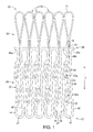
FIG. 1 is a side view of a stent, which may be coupled to a graft to form a stent-graft in accordance with an embodiment, in a delivery configuration, depicted as flattened for illustrative purposes; -
FIG. 2 is a perspective view or the stent ofFIG. 1 in a cylindrical, compressed delivery configuration; -
FIG. 3 is a side view of the stent ofFIGS. 1 and2 in a deployed configuration, depicted as flattened for illustrative purposes; -
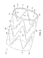
FIG. 4 is a perspective view of the stent ofFIGS. 1 and2 in a cylindrical, deployed configuration; -
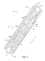
FIG. 5 is a perspective view of an exemplary delivery system that may be used to deliver the stent ofFIGS. 1-4 , where the stent is coupled to a graft to form a stent-graft; -
FIG. 6 is a perspective view of the stent ofFIGS. 1-4 , coupled to a graft to form a stent-graft, in a deployed configuration; and -
FIGS. 7A-7C are side views depicting deployed configurations of the proximal conformance strut of the stent ofFIGS. 1-6 . - In the present application, the term "proximal" refers to a direction that is generally closest to the heart during a medical procedure, while the term "distal" refers to a direction that is furthest from the heart during a medical procedure. Referring to
FIGS. 1 and2 , astent 20, which may be coupled to a graft to form a stent-graft according to an embodiment, may be manufactured from a continuous cylinder into which a pattern may be cut by a laser or by chemical etching to produce slits in the wall of the cylinder.FIG. 2 shows the cannula-cut pattern of thestent 20 in a compressed, delivery configuration. At least a portion of the cannula-cut structure may then be heat set to give it a desired final expanded, deployed configuration, as generally shown and explained with respect toFIGS. 3 and 4 below. - The
stent 20 comprises two sections, namely aproximal region 22 having one or moreproximal conformance struts 70, and adistal region 24 having amain body 30, as shown inFIGS. 1 and2 . Themain body 30 may comprise a generally zig-zag shape in the deployed configuration, having aproximal end 36 and adistal end 37, as shown inFIGS. 3 and 4 (see below). Themain body 30 may be formed from a continuous main body segment having a plurality of substantially straightfirst segments 42 andsecond segments 44. A plurality of proximal apices 46 anddistal apices 47 are disposed between thefirst segments 42 andsecond segments 44, as shown inFIGS. 1-4 . - As will be explained in greater detail with respect to
FIGS. 5 and6 below, themain body 30 of thestent 20 is coupled to agraft material 120 to form a stent-graft 110. Accordingly, portions of themain body 30, such as regions of the first andsecond segments graft material 120 using known suturing techniques. Theproximal region 22 having one or more proximal conformance struts 70 preferably is not sutured to thegraft material 120, for purposes explained in greater detail below. - Referring to
FIGS. 1-4 , one or more integral barbs 50 may be formed in one or more of the plurality of substantially straightfirst segments 42 andsecond segments 44 of themain body 30. The barbs 50 may be formed by laser cutting a desired barb shape into the struts that form thefirst segments 42 and/orsecond segments 44. A slit 51 therefore is formed into the struts that form thefirst segments 42 and/orsecond segments 44 after the desired barb shape is formed, as shown inFIGS. 1 and2 . Once the desired barb shape is cut, amain body 52 of the barb 50 may be bent in a radially outward direction with respect to thefirst segments 42 and/orsecond segments 44. The angle may comprise any acute angle, as generally shown inFIG. 4 andFIG. 6 , or alternatively may be substantially orthogonal or obtuse. If desired, the barbs 50 may be sharpened, for example, by grinding thetip 53 of the barb, to facilitate engagement at a target tissue site. - As shown in
FIGS. 1-4 , first andsecond barbs second segments 44 forming themain body 30 of thestent 20. If integrally formed, thebarbs second segments 44 that comprise larger surface areas relative to thefirst segments 42. Since the portions of thesecond segments 44 housing thebarbs stent 20, it may be easier to perforate portions of thesecond segments 44 to form the barbs integrally, without adversely affecting the structural integrity of the stent. - While the
barbs second segments 44, it will be apparent that one or more barbs may be integrally formed in both the first andsecond segments integral barbs stent 20 may comprise only external barbs that are adhered to a surface of thefirst segments 42 and/or thesecond segments 44, or thestent 20 alternatively may comprise a combination of integral barbs and externally adhered barbs. - As noted above, the
proximal region 22 of thestent 20 comprises one or more proximal conformance struts 70 disposed between adjacent apices. The proximal conformance struts 70 may be integrally formed with theproximal end 36 of themain body 30, as depicted herein, for example, by way of forming the stent by laser cutting. Alternatively, the proximal conformance struts 70 may be adhered to theproximal end 36 of themain body 30 at one or more locations, for example, using a solder or weld. - The proximal conformance struts 70 comprise a
first end 73, asecond end 74, and acentral region 77 formed therebetween. Thefirst end 73 of eachproximal conformance strut 70 may be formed integrally with themain body 30, preferably where one apex 46a of themain body 30 meets a correspondingfirst segment 42 of the main body, as seen inFIGS. 1-4 . Thesecond end 74 of theproximal conformance strut 70 may be formed integrally with themain body 30, preferably near a region where a secondproximal apex 46b meets a correspondingsecond segment 44 of the main body, as shown inFIGS. 1-4 . Therefore, in the expanded configuration shown inFIGS. 3 and 4 , eachproximal conformance strut 70 may be deployed substantially between a firstproximal apex 46a and an adjacent, secondproximal apex 46b. As will be set forth in greater detail inFIG. 6 below, the proximal conformance struts 70 may be designed to fill in open spaces between the adjacentproximal apices graft material 120 bowing in a radially inward direction. - Referring to the compressed delivery configuration shown in
FIGS. 1 and2 and 5, thefirst end 73 of eachproximal conformance strut 70 may extend in a substantially longitudinal direction away from its respective proximal apex 46, i.e., in a direction parallel to a longitudinal axis L of thestent 20, as shown inFIG. 1 . Similarly, thesecond end 74 of eachproximal conformance strut 70 may extend in a substantially longitudinal direction away from its respective proximal apex 46. Thecentral region 77 formed between the first and second ends 73, 74 of each proximal conformance struts 70 may form a loop or arcuate shape in the compressed delivery configuration, spanning approximately 180 degrees between the first and second ends 73, 74, as shown inFIGS. 1 ,2 and5 . - In an embodiment, the proximal conformance struts 70 do not overlap with the
main body 30 of thestent 20 in the compressed delivery configuration, as shown inFIGS. 1 ,2 and5 . Accordingly, thestent 20 may be compressed to a relatively small delivery profile, as shown inFIG. 5 , and therefore may be delivered into smaller vessels or ducts. - In an embodiment, each
proximal conformance strut 70 may have a depth (e.g., cannula thickness) that is greater than its width (as shown from the side view ofFIG. 1 ). In this embodiment, with such dimensions the moment of inertia may help drive the conformance struts 70 to form the loop or arcuate shape in the compressed delivery configuration, as shown inFIGS. 1 ,2 and5 . - The
main body 30 and the proximal conformance struts 70 of thestent 20 may be held in the compressed delivery configuration ofFIGS. 1 and2 using asuitable delivery system 90, as depicted inFIG. 5 . In one exemplary embodiment, thedelivery system 90 may comprise anouter sheath 92 configured to surround and constrain thestent 20 and thegraft material 120 in the delivery configuration. When the constrainingouter sheath 92 is removed, themain body 30 and the proximal conformance struts 70 of thestent 20 may assume their respective deployed configurations, as shown inFIGS. 3-4 andFIG. 6 . Themain body 30 and the proximal conformance struts 70 of thestent 20 may assume their respective deployed configurations either due to the inherent resiliency of the material and/or via heat-set properties of the material. Preferably, at least the proximal conformance struts 70 are heat-set to assume a predetermined deployed configuration upon removal of theouter sheath 92. Themain body 30 may be heat-set into the desired zig-zag deployed shape, as shown inFIGS. 3, 4 and6 , or alternatively may assume the zig-zag deployed shape due to the inherent expansile properties of the material forming themain body 30. - In the expanded deployed configuration, as shown in
FIGS. 3, 4 and6 , thestent 20 preferably applies a radially outward force upon at least a portion of a vessel or duct, e.g., to maintain patency within a passageway, or to hold open the lumen of a graft. In the expanded configuration, fluid flow is allowed through acentral lumen 135 of thestent 20. It should be noted that the struts of thestent 20 are generally shown having a substantially flat cross-sectional profile, as depicted inFIG. 2 andFIG. 4 , but alternatively may comprise a rounded cross-sectional profile or other suitable configuration. - The
stent 20 may be manufactured from a superelastic material. Solely by way of example, the superelastic material may comprise a shape-memory alloy, such as a nickel titanium alloy (nitinol). If thestent 20 comprises a self-expanding material such as nitinol, the stent may be heat-set into the desired expanded configuration, whereby thestent 20 can assume a relaxed configuration in which it assumes the preconfigured first expanded inner diameter upon application of a certain cold or hot medium. Alternatively, thestent 20 may be made from other metals and alloys that allow thestent 20 to return to its original, expanded configuration upon deployment, without inducing a permanent strain on the material due to compression. Solely by way of example, thestent 20 may comprise other materials such as stainless steel, cobalt-chrome alloys, amorphous metals, tantalum, platinum, gold and/or titanium. Thestent 20 also may be made from non-metallic materials, such as thermoplastics and other polymers. - The proximal conformance struts 70 may assume a variety of shapes in the deployed configuration. As shown in
FIGS. 3, 4 and7A , the proximal conformance struts 70 may assume a wave-shaped configuration in the deployed configuration having one ormore peaks 78 andvalleys 79 formed between the first and second ends 73, 74. Alternatively, the proximal conformance struts 70 may assume aconcave configuration 82 relative to themain body 30, as shown inFIG. 7B , or aconvex configuration 84 relative to themain body 30, as shown inFIG. 7C and explained in greater detail below. - As shown in
FIGS. 5 and6 , themain body 30 of thestent 20 is coupled to agraft material 120 to form a stent-graft 110. Regions of the first andsecond segments graft material 120 using known suturing techniques. The proximal conformance struts 70, in contrast, are not sutured to thegraft material 120. Rather, as shown inFIG. 5 , a portion of at least oneproximal conformance strut 70 extends proximal to theproximal end 122 of thegraft material 120 in the compressed delivery configuration. As noted above, overlap between themain body 30 and the proximal conformance struts 70 therefore is avoided during delivery, allowing for delivery of thestent 20 and associated stent-graft 110 into smaller vessels. - In
FIG. 5 , thestent 20 and associated stent-graft 110 may be delivered to a target site in the compressed delivery configuration using thedelivery system 90 noted above, which may comprise theouter sheath 92, along with one ormore trigger wires 94 and adilator 96. Acannula 98 having a lumen formed therein may be employed and may extend substantially the entire longitudinal length of thedelivery system 90. Thecannula 98 may be advanced over a previously-placed wire guide, thereby facilitating advancement of thedelivery system 90 to a target site. - The
exemplary dilator 96 may comprise a main body and a taperedregion 97, which facilitates proximal advancement of thedelivery system 90 over a wire guide. In particular, a relatively small diameter of the taperedregion 97 may allow for atraumatic access and delivery. The one ormore trigger wires 94 may be disposed within the confines of theouter sheath 92 and thegraft material 120, and may span substantially the entire length of thedelivery system 90. - The one or
more trigger wires 94 may be used to restrain one or more of the proximal conformance struts 70 during delivery of the stent-graft 110. In one embodiment, asingle trigger wire 94 may be looped through selected ones of the proximal conformance struts 70 to restrain thestent 20 during delivery. Preferably, eachtrigger wire 94 is looped through a correspondingcentral region 77 of at least oneproximal conformance strut 70 to help maintain the proximal end of thestent 30 in a radially compressed configuration. It should be noted that it is not necessary to have an equal number oftrigger wires 94 and proximal conformance struts 70, e.g., atrigger wires 94 may only restrain every otherproximal conformance strut 70, or anindividual trigger wire 94 may be used to restrain multiple adjacent proximal conformance struts 70. - In use, as the stent-
graft 120 is delivered towards a target site, theouter sheath 92 preferably is positioned proximally over the entirety of the stent-graft 110, i.e., theouter sheath 92 covers themain body 30 coupled to thegraft material 120, and also covers the proximal conformance struts 70. Theouter sheath 92 therefore ensures that the entirety of thestent 30 is held in a compressed delivery configuration. When the stent-graft 110 is positioned at a desired location using a suitable imaging technique such as fluoroscopy, a physician may distally retract theouter sheath 92 to expose at least the proximal conformance struts 70. At this time, the proximal conformance struts 70 are still restrained by the one ormore trigger wires 94. Therefore, the proximal conformance struts 70 do not expand fully radially outward into engagement with a vessel or duct, and a physician may further tweak or adjust the positioning of the stent-graft 110 relative to the vessel or duct. - When the proper final positioning has been confirmed, the physician may further retract the
outer sheath 92, thereby exposing themain body 30 of the stent-graft 110. When no longer radially constrained, themain body 30 of thestent 20 will expand in a radially-outward direction, as shown inFIG. 6 . At this time, portions of thegraft material 120 may be urged into engagement with an inner wall of a vessel or duct, and may allow flow through the vessel or duct via thecentral lumen 135. - In a next step, the physician may actuate the one or
more trigger wires 94 to release the proximal conformance struts 70, thereby allowing each of the proximal conformance struts 70 to assume the expanded deployed configuration shown inFIG. 6 . In the expanded configuration, the proximal conformance struts 70 preferably are aligned inside theproximal end 122 of thegraft material 120, as depicted inFIG. 6 . When deployed, the proximal conformance struts 70 preferably are disposed substantially perpendicular to the longitudinal axis L and may fill in at least some of the radial spaces between adjacentproximal apices proximal apices proximal end 122 of thegraft material 120, as shown inFIG. 6 . - Advantageously, by at least partially encircling the
graft material 120 just distal to theproximal end 122 of thegraft material 120, the proximal conformance struts 70 may provide enhanced radial support to thegraft material 120, which may reduce the likelihood that blood flow may catch on the proximal edge of the graft material. Blood that flows in a distal direction through the stent-graft 110 therefore is less likely to pull theproximal edge 122 of thegraft material 120 in a radially inward direction, which may impede blood flow through thecentral lumen 135 and cause potential endoleaks. Furthermore, the use of astent 20 as part of a stent-graft 110 may be better suited for use in a curved portion of a vessel, such as the aortic arch or thoracic aorta, where it may be difficult to conform the proximal edge of a stent-graft to the curving vessel wall. - The stent-
graft 110 may find particular use in applications where it may not be desirable to have a bare stent segment extending proximal or distal to thegraft material 120 in the deployed configuration. As shown inFIG. 6 , the entirety of thestent 20 is contained between the proximal anddistal ends - It will be noted that the stent-
graft 110 ofFIG. 6 is shown having an additional zig-zag shapedstent 140 disposed distal to thestent 20 described above. Theadditional stent 140 may be designed similar to thestent 20, with the exception that the conformance struts 70 are omitted, as shown inFIG. 6 . Theadditional stent 140 may be sutured to thegraft material 120 at a location distal to thestent 20 and may provide radial support towards thedistal end 124 of thegraft material 120. - While one additional exemplary zig-
zag stent 140 is shown as part of the stent-graft 110 inFIG. 6 , the stent-graft 110 may have any number of stents having any variety of shapes, so long as the most proximal stent embodies at least one of the proximal conformance struts 70 described above. In particular, themain body 30 of the proximal-most stent can have struts forming configurations besides zig-zag shapes, and the one or more proximal conformance struts 70 can be used to fill in any open spaces between the struts to help support thegraft material 120. Furthermore, while a singleproximal conformance strut 70 has been shown between each and every adjacentproximal apex - In still further applications, distal conformance struts, which may be substantially identical to the proximal conformance struts 70 described herein, may be used to support the
distal end 124 of thegraft material 120. Such distal conformance struts may be used in lieu of, or in conjunction with, the proximal conformance struts 70 to help prevent thedistal end 124 of thegraft material 120 from folding inward. - Additionally, it should be noted that the proximal conformance struts 70 preferably are substantially the same radial diameter as the
main body 30, when both themain body 30 and the proximal conformance struts are in their respective deployed configurations. In effect, the proximal conformance struts 70 do not substantially bend radially inward or outward relative to themain body 30, and therefore do not substantially urge thegraft material 120 inward or outward relative to the proximal apices 46. - Referring to
FIGS. 7A-7C , the proximal conformance struts 70 may assume a variety of shapes in the deployed configuration. As shown inFIG. 7A , the proximal conformance struts 70 may assume a wave-shaped configuration in the deployed configuration having one ormore peaks 78 andvalleys 79 formed between the first and second ends 73 and 74. Alternatively, a proximal conformance strut 70' may assume aconcave configuration 82 relative to themain body 30, as shown inFIG. 7B , while aproximal conformance strut 70" may comprise aconvex configuration 84 relative to themain body 30, as shown inFIG. 7C . - These proximal conformance strut shapes of
FIGS. 7A-7C may be designed to have different advantages. Solely by way of example, the proximal conformance struts 70 ofFIG. 7A may provide enhanced rigidity due to the alternating convex and concave portions. As an alternative, the singularly concave-shaped proximal conformance struts 70' ofFIG. 7B may help resist inward movement of thedistal end 122 of thegraft material 120 by extending proximally away from themain body 30. As a further alternative, the singularly convex-shaped proximal conformance struts 70" ofFIG. 7C may advantageously help the distal end of thestent 20 better conform to bends in a vessel and provide an enhanced seal. Still further alternative deployed configurations of the proximal conformance struts may be employed are within the scope of the present invention. - It should be noted that the proximal conformance struts 70 may comprise a reduced profile, including but not limited to width, thickness and/or cross-sectional area, relative to the first and
second segments main body 30. For example, as depicted in the Figures, the proximal conformance struts 70 generally are narrower in width than themain body 30, which may assist in deployment of the proximal conformance struts 70 from the compressed to expanded configurations. Since a main function of the proximal conformance struts 70 is to resist inward movement of thegraft material 120, as opposed to holding open a vessel or duct, the proximal conformance struts 70 can comprise such a reduced profile relative to themain body 30. - While various embodiments of the invention have been described, the invention is not to be restricted except in light of the attached claims and their equivalents. Moreover, the advantages described herein are not necessarily the only advantages of the invention and it is not necessarily expected that every embodiment of the invention will achieve all of the advantages described.
Claims (11)
- A stent-graft (110) for use in a medical procedure, the stent-graft comprising:a substantially tubular graft material (120); andat least one stent (20) coupled to the graft material and having compressed and deployed configurations,wherein a proximal end (36) of the stent comprises at least one conformance strut (70) having a compressed delivery configuration and an expanded deployed configuration, andwherein, in the compressed delivery configuration, the at least one conformance strut comprises an outwardly extending loop that is substantially parallel to a longitudinal axis (L) of the stent and extends beyond a proximal end (122) of the graft material, andwherein, in the deployed configuration, the at least one conformance strut is disposed substantially perpendicular to the longitudinal axis and is aligned inside the proximal end of the graft material.
- A stent-graft (110) as claimed in claim 1, wherein the at least one conformance strut (70) is integrally formed with the stent.
- A stent-graft (110) as claimed in claim 1 or 2, wherein the stent comprises a zig-zag shape having a plurality of proximal apices (46) and distal apices (47), and wherein at least one conformance strut (70) is disposed between adjacent proximal apices.
- A stent-graft (110) as claimed in claim 3, wherein each proximal apex (46) is connected to the next adjacent proximal apex by a conformance strut (70) to form a proximal conformance ring when the conformance struts are in the deployed configuration.
- A stent-graft (110) as claimed in any preceding claim, wherein, in the deployed configuration, the at least one conformance strut (70) is wave-shaped.
- A stent-graft (110) as claimed in any of claims 1 to 4, wherein, in the deployed configuration, the at least one conformance strut (70) is concave-shaped relative to a main body (30) of the stent.
- A stent-graft (110) as claimed in any of claims 1 to 4 wherein, in the deployed configuration, the at least one conformance strut (70) is convex-shaped relative to a main body (30) of the stent.
- A stent-graft (110) as claimed in any preceding claim, wherein the stent comprises a main body (30) comprising a zig-zag shape in the deployed configuration with a plurality of substantially straight first segments (42) and second segments (44) having a plurality of proximal apices (46) and distal apices (48) disposed therebetween, the stent further comprising at least one integral barb (50) formed in at least one of the first segment or second segment of the main body.
- A stent-graft (110) as claimed in any preceding claim, comprising at least one distal conformance strut.
- A delivery device (90) including a stent-graft (110) as claimed in any one of claims 1 to 8 mounted thereon.
- A delivery device (90) as claimed in claim 10, including one or more trigger wires (94) to restrain one or more of the proximal conformance struts (70) during delivery.
Applications Claiming Priority (2)
| Application Number | Priority Date | Filing Date | Title |
|---|---|---|---|
| US13864308P | 2008-12-18 | 2008-12-18 | |
| PCT/US2009/068201 WO2010080427A1 (en) | 2008-12-18 | 2009-12-16 | Stents and stent grafts |
Publications (2)
| Publication Number | Publication Date |
|---|---|
| EP2358302A1 EP2358302A1 (en) | 2011-08-24 |
| EP2358302B1 true EP2358302B1 (en) | 2012-12-05 |
Family
ID=41809912
Family Applications (1)
| Application Number | Title | Priority Date | Filing Date |
|---|---|---|---|
| EP09775486A Active EP2358302B1 (en) | 2008-12-18 | 2009-12-16 | Stents and stent grafts |
Country Status (3)
| Country | Link |
|---|---|
| US (1) | US8672992B2 (en) |
| EP (1) | EP2358302B1 (en) |
| WO (1) | WO2010080427A1 (en) |
Families Citing this family (47)
| Publication number | Priority date | Publication date | Assignee | Title |
|---|---|---|---|---|
| US20070198078A1 (en) | 2003-09-03 | 2007-08-23 | Bolton Medical, Inc. | Delivery system and method for self-centering a Proximal end of a stent graft |
| US7763063B2 (en) | 2003-09-03 | 2010-07-27 | Bolton Medical, Inc. | Self-aligning stent graft delivery system, kit, and method |
| US8292943B2 (en) | 2003-09-03 | 2012-10-23 | Bolton Medical, Inc. | Stent graft with longitudinal support member |
| US11259945B2 (en) | 2003-09-03 | 2022-03-01 | Bolton Medical, Inc. | Dual capture device for stent graft delivery system and method for capturing a stent graft |
| US8500792B2 (en) | 2003-09-03 | 2013-08-06 | Bolton Medical, Inc. | Dual capture device for stent graft delivery system and method for capturing a stent graft |
| US9198786B2 (en) | 2003-09-03 | 2015-12-01 | Bolton Medical, Inc. | Lumen repair device with capture structure |
| US11596537B2 (en) | 2003-09-03 | 2023-03-07 | Bolton Medical, Inc. | Delivery system and method for self-centering a proximal end of a stent graft |
| US20080264102A1 (en) | 2004-02-23 | 2008-10-30 | Bolton Medical, Inc. | Sheath Capture Device for Stent Graft Delivery System and Method for Operating Same |
| AU2006315812B2 (en) | 2005-11-10 | 2013-03-28 | Cardiaq Valve Technologies, Inc. | Balloon-expandable, self-expanding, vascular prosthesis connecting stent |
| EP3219292B1 (en) * | 2008-06-30 | 2019-08-14 | Bolton Medical Inc. | Abdominal aortic aneurysms systems |
| EP2901966B1 (en) * | 2008-09-29 | 2016-06-29 | Edwards Lifesciences CardiAQ LLC | Heart valve |
| US8337541B2 (en) | 2008-10-01 | 2012-12-25 | Cardiaq Valve Technologies, Inc. | Delivery system for vascular implant |
| ES2639311T3 (en) | 2009-03-13 | 2017-10-26 | Bolton Medical Inc. | System and method to deploy an endoluminal prosthesis in a surgical site |
| EP2419050B2 (en) | 2009-04-15 | 2023-10-18 | Edwards Lifesciences CardiAQ LLC | Vascular implant and delivery system |
| US9730790B2 (en) | 2009-09-29 | 2017-08-15 | Edwards Lifesciences Cardiaq Llc | Replacement valve and method |
| US8579964B2 (en) | 2010-05-05 | 2013-11-12 | Neovasc Inc. | Transcatheter mitral valve prosthesis |
| EP3459500B1 (en) | 2010-09-23 | 2020-09-16 | Edwards Lifesciences CardiAQ LLC | Replacement heart valves and delivery devices |
| US8475372B2 (en) | 2010-10-29 | 2013-07-02 | Medtronic Vascular, Inc. | Implantable medical sensor and fixation system |
| US8864676B2 (en) | 2010-10-29 | 2014-10-21 | Medtronic Vascular, Inc. | Implantable medical sensor and fixation system |
| US8727996B2 (en) | 2011-04-20 | 2014-05-20 | Medtronic Vascular, Inc. | Delivery system for implantable medical device |
| US9554897B2 (en) | 2011-04-28 | 2017-01-31 | Neovasc Tiara Inc. | Methods and apparatus for engaging a valve prosthesis with tissue |
| US9308087B2 (en) | 2011-04-28 | 2016-04-12 | Neovasc Tiara Inc. | Sequentially deployed transcatheter mitral valve prosthesis |
| US8728148B2 (en) | 2011-11-09 | 2014-05-20 | Cook Medical Technologies Llc | Diameter reducing tie arrangement for endoluminal prosthesis |
| US9629737B2 (en) | 2011-12-23 | 2017-04-25 | Cook Medical Technologies Llc | Delivery system for staged stent release |
| US8992595B2 (en) * | 2012-04-04 | 2015-03-31 | Trivascular, Inc. | Durable stent graft with tapered struts and stable delivery methods and devices |
| EP2846743B1 (en) | 2012-04-12 | 2016-12-14 | Bolton Medical Inc. | Vascular prosthetic delivery device |
| US9345573B2 (en) | 2012-05-30 | 2016-05-24 | Neovasc Tiara Inc. | Methods and apparatus for loading a prosthesis onto a delivery system |
| US9351648B2 (en) | 2012-08-24 | 2016-05-31 | Medtronic, Inc. | Implantable medical device electrode assembly |
| EP2777604B1 (en) | 2013-01-23 | 2018-10-03 | Cook Medical Technologies LLC | Stent with positioning arms |
| US10583002B2 (en) | 2013-03-11 | 2020-03-10 | Neovasc Tiara Inc. | Prosthetic valve with anti-pivoting mechanism |
| US10561509B2 (en) | 2013-03-13 | 2020-02-18 | DePuy Synthes Products, Inc. | Braided stent with expansion ring and method of delivery |
| US9681951B2 (en) | 2013-03-14 | 2017-06-20 | Edwards Lifesciences Cardiaq Llc | Prosthesis with outer skirt and anchors |
| US9730791B2 (en) | 2013-03-14 | 2017-08-15 | Edwards Lifesciences Cardiaq Llc | Prosthesis for atraumatically grasping intralumenal tissue and methods of delivery |
| US9439751B2 (en) | 2013-03-15 | 2016-09-13 | Bolton Medical, Inc. | Hemostasis valve and delivery systems |
| US9572665B2 (en) | 2013-04-04 | 2017-02-21 | Neovasc Tiara Inc. | Methods and apparatus for delivering a prosthetic valve to a beating heart |
| USD755384S1 (en) | 2014-03-05 | 2016-05-03 | Edwards Lifesciences Cardiaq Llc | Stent |
| US10206796B2 (en) | 2014-08-27 | 2019-02-19 | DePuy Synthes Products, Inc. | Multi-strand implant with enhanced radiopacity |
| US10350062B2 (en) | 2016-07-21 | 2019-07-16 | Edwards Lifesciences Corporation | Replacement heart valve prosthesis |
| US10076428B2 (en) | 2016-08-25 | 2018-09-18 | DePuy Synthes Products, Inc. | Expansion ring for a braided stent |
| US10292851B2 (en) | 2016-09-30 | 2019-05-21 | DePuy Synthes Products, Inc. | Self-expanding device delivery apparatus with dual function bump |
| CN107569311A (en) * | 2017-07-05 | 2018-01-12 | 杭州唯强医疗科技有限公司 | Ring holder |
| CN111818877B (en) | 2018-01-25 | 2023-12-22 | 爱德华兹生命科学公司 | Delivery system for assisting in recapture and repositioning of replacement valves after deployment |
| AU2019204522A1 (en) | 2018-07-30 | 2020-02-13 | DePuy Synthes Products, Inc. | Systems and methods of manufacturing and using an expansion ring |
| US10278848B1 (en) | 2018-08-06 | 2019-05-07 | DePuy Synthes Products, Inc. | Stent delivery with expansion assisting delivery wire |
| US10456280B1 (en) | 2018-08-06 | 2019-10-29 | DePuy Synthes Products, Inc. | Systems and methods of using a braided implant |
| US11039944B2 (en) | 2018-12-27 | 2021-06-22 | DePuy Synthes Products, Inc. | Braided stent system with one or more expansion rings |
| CN115501020A (en) * | 2021-06-22 | 2022-12-23 | 微创神通医疗科技(上海)有限公司 | Support and medicine-carrying support |
Family Cites Families (19)
| Publication number | Priority date | Publication date | Assignee | Title |
|---|---|---|---|---|
| DE69118083T2 (en) * | 1990-10-09 | 1996-08-22 | Cook Inc | Percutaneous stent assembly |
| US6602281B1 (en) * | 1995-06-05 | 2003-08-05 | Avantec Vascular Corporation | Radially expansible vessel scaffold having beams and expansion joints |
| NZ331269A (en) * | 1996-04-10 | 2000-01-28 | Advanced Cardiovascular System | Expandable stent, its structural strength varying along its length |
| US6464723B1 (en) * | 1999-04-22 | 2002-10-15 | Advanced Cardiovascular Systems, Inc. | Radiopaque stents |
| US20030070676A1 (en) * | 1999-08-05 | 2003-04-17 | Cooper Joel D. | Conduits having distal cage structure for maintaining collateral channels in tissue and related methods |
| US7462162B2 (en) * | 2001-09-04 | 2008-12-09 | Broncus Technologies, Inc. | Antiproliferative devices for maintaining patency of surgically created channels in a body organ |
| US6379382B1 (en) * | 2000-03-13 | 2002-04-30 | Jun Yang | Stent having cover with drug delivery capability |
| WO2004017866A1 (en) * | 2002-08-20 | 2004-03-04 | Cook Incorporated | Stent graft with improved proximal end |
| WO2005034807A1 (en) * | 2003-10-10 | 2005-04-21 | William A. Cook Australia Pty. Ltd | Composite stent graft |
| US8012201B2 (en) * | 2004-05-05 | 2011-09-06 | Direct Flow Medical, Inc. | Translumenally implantable heart valve with multiple chamber formed in place support |
| JP2008541868A (en) * | 2005-05-23 | 2008-11-27 | インセプト・リミテッド・ライアビリティ・カンパニー | Mechanically actuated stents and devices and methods for placing them |
| WO2007028086A2 (en) * | 2005-09-01 | 2007-03-08 | Medtronic Vascular, Inc. | Methods and apparatus for treatment of thoracic aortic aneurysms |
| US8083792B2 (en) * | 2006-01-24 | 2011-12-27 | Cordis Corporation | Percutaneous endoprosthesis using suprarenal fixation and barbed anchors |
| US20070233233A1 (en) | 2006-03-31 | 2007-10-04 | Boston Scientific Scimed, Inc | Tethered expansion columns for controlled stent expansion |
| US8632581B2 (en) * | 2006-07-10 | 2014-01-21 | Cook Medical Technologies Llc | Conformable end sealing stent |
| US8460362B2 (en) * | 2006-07-20 | 2013-06-11 | Orbusneich Medical, Inc. | Bioabsorbable polymeric medical device |
| US9044311B2 (en) * | 2006-11-30 | 2015-06-02 | Cook Medical Technologies Llc | Aortic graft device |
| US20090149946A1 (en) * | 2007-12-05 | 2009-06-11 | Cook Incorporated | Stent having at least one barb and methods of manufacture |
| WO2010042854A1 (en) * | 2008-10-10 | 2010-04-15 | Orbusneich Medical, Inc. | Bioabsorbable polymeric medical device |
-
2009
- 2009-12-16 WO PCT/US2009/068201 patent/WO2010080427A1/en active Application Filing
- 2009-12-16 EP EP09775486A patent/EP2358302B1/en active Active
- 2009-12-17 US US12/641,125 patent/US8672992B2/en active Active
Also Published As
| Publication number | Publication date |
|---|---|
| US20100161027A1 (en) | 2010-06-24 |
| US8672992B2 (en) | 2014-03-18 |
| WO2010080427A1 (en) | 2010-07-15 |
| EP2358302A1 (en) | 2011-08-24 |
Similar Documents
| Publication | Publication Date | Title |
|---|---|---|
| EP2358302B1 (en) | Stents and stent grafts | |
| US20180071122A1 (en) | Stent designs for use with one or more trigger wires | |
| JP6441297B2 (en) | Stent and stent graft | |
| US9370437B2 (en) | Stent having less invasive ends | |
| JP5945119B2 (en) | Apparatus and method for improved stent deployment | |
| US20090149946A1 (en) | Stent having at least one barb and methods of manufacture | |
| EP2801340B1 (en) | Stents having barbs protected during delivery | |
| US8128678B2 (en) | Stent having less invasive ends and improved radial force | |
| EP2745811B1 (en) | Systems for securing and releasing a portion of a stent | |
| CN107666883B (en) | Stent graft device with anchor member having adjustable geometry | |
| EP2745806B1 (en) | Stent designs for reduced infolding of graft material | |
| EP2727558B1 (en) | Suture attachments for coupling a stent to graft material | |
| US20200268533A1 (en) | Hybrid stent designs | |
| AU2014213580B2 (en) | Stent and stent-graft designs |
Legal Events
| Date | Code | Title | Description |
|---|---|---|---|
| PUAI | Public reference made under article 153(3) epc to a published international application that has entered the european phase |
Free format text: ORIGINAL CODE: 0009012 |
|
| 17P | Request for examination filed |
Effective date: 20110609 |
|
| AK | Designated contracting states |
Kind code of ref document: A1 Designated state(s): AT BE BG CH CY CZ DE DK EE ES FI FR GB GR HR HU IE IS IT LI LT LU LV MC MK MT NL NO PL PT RO SE SI SK SM TR |
|
| RAP1 | Party data changed (applicant data changed or rights of an application transferred) |
Owner name: COOK MEDICAL TECHNOLOGIES LLC |
|
| DAX | Request for extension of the european patent (deleted) | ||
| 17Q | First examination report despatched |
Effective date: 20120412 |
|
| GRAP | Despatch of communication of intention to grant a patent |
Free format text: ORIGINAL CODE: EPIDOSNIGR1 |
|
| GRAS | Grant fee paid |
Free format text: ORIGINAL CODE: EPIDOSNIGR3 |
|
| GRAA | (expected) grant |
Free format text: ORIGINAL CODE: 0009210 |
|
| AK | Designated contracting states |
Kind code of ref document: B1 Designated state(s): AT BE BG CH CY CZ DE DK EE ES FI FR GB GR HR HU IE IS IT LI LT LU LV MC MK MT NL NO PL PT RO SE SI SK SM TR |
|
| REG | Reference to a national code |
Ref country code: GB Ref legal event code: FG4D |
|
| REG | Reference to a national code |
Ref country code: CH Ref legal event code: EP |
|
| REG | Reference to a national code |
Ref country code: AT Ref legal event code: REF Ref document number: 586849 Country of ref document: AT Kind code of ref document: T Effective date: 20121215 |
|
| REG | Reference to a national code |
Ref country code: IE Ref legal event code: FG4D |
|
| REG | Reference to a national code |
Ref country code: DE Ref legal event code: R096 Ref document number: 602009011783 Country of ref document: DE Effective date: 20130124 |
|
| REG | Reference to a national code |
Ref country code: AT Ref legal event code: MK05 Ref document number: 586849 Country of ref document: AT Kind code of ref document: T Effective date: 20121205 |
|
| PG25 | Lapsed in a contracting state [announced via postgrant information from national office to epo] |
Ref country code: SE Free format text: LAPSE BECAUSE OF FAILURE TO SUBMIT A TRANSLATION OF THE DESCRIPTION OR TO PAY THE FEE WITHIN THE PRESCRIBED TIME-LIMIT Effective date: 20121205 Ref country code: ES Free format text: LAPSE BECAUSE OF FAILURE TO SUBMIT A TRANSLATION OF THE DESCRIPTION OR TO PAY THE FEE WITHIN THE PRESCRIBED TIME-LIMIT Effective date: 20130316 Ref country code: NO Free format text: LAPSE BECAUSE OF FAILURE TO SUBMIT A TRANSLATION OF THE DESCRIPTION OR TO PAY THE FEE WITHIN THE PRESCRIBED TIME-LIMIT Effective date: 20130305 Ref country code: LT Free format text: LAPSE BECAUSE OF FAILURE TO SUBMIT A TRANSLATION OF THE DESCRIPTION OR TO PAY THE FEE WITHIN THE PRESCRIBED TIME-LIMIT Effective date: 20121205 Ref country code: FI Free format text: LAPSE BECAUSE OF FAILURE TO SUBMIT A TRANSLATION OF THE DESCRIPTION OR TO PAY THE FEE WITHIN THE PRESCRIBED TIME-LIMIT Effective date: 20121205 |
|
| REG | Reference to a national code |
Ref country code: NL Ref legal event code: VDEP Effective date: 20121205 |
|
| REG | Reference to a national code |
Ref country code: LT Ref legal event code: MG4D |
|
| PG25 | Lapsed in a contracting state [announced via postgrant information from national office to epo] |
Ref country code: SI Free format text: LAPSE BECAUSE OF FAILURE TO SUBMIT A TRANSLATION OF THE DESCRIPTION OR TO PAY THE FEE WITHIN THE PRESCRIBED TIME-LIMIT Effective date: 20121205 Ref country code: GR Free format text: LAPSE BECAUSE OF FAILURE TO SUBMIT A TRANSLATION OF THE DESCRIPTION OR TO PAY THE FEE WITHIN THE PRESCRIBED TIME-LIMIT Effective date: 20130306 Ref country code: PL Free format text: LAPSE BECAUSE OF FAILURE TO SUBMIT A TRANSLATION OF THE DESCRIPTION OR TO PAY THE FEE WITHIN THE PRESCRIBED TIME-LIMIT Effective date: 20121205 Ref country code: LV Free format text: LAPSE BECAUSE OF FAILURE TO SUBMIT A TRANSLATION OF THE DESCRIPTION OR TO PAY THE FEE WITHIN THE PRESCRIBED TIME-LIMIT Effective date: 20121205 |
|
| PG25 | Lapsed in a contracting state [announced via postgrant information from national office to epo] |
Ref country code: AT Free format text: LAPSE BECAUSE OF FAILURE TO SUBMIT A TRANSLATION OF THE DESCRIPTION OR TO PAY THE FEE WITHIN THE PRESCRIBED TIME-LIMIT Effective date: 20121205 |
|
| PG25 | Lapsed in a contracting state [announced via postgrant information from national office to epo] |
Ref country code: IS Free format text: LAPSE BECAUSE OF FAILURE TO SUBMIT A TRANSLATION OF THE DESCRIPTION OR TO PAY THE FEE WITHIN THE PRESCRIBED TIME-LIMIT Effective date: 20130405 Ref country code: BG Free format text: LAPSE BECAUSE OF FAILURE TO SUBMIT A TRANSLATION OF THE DESCRIPTION OR TO PAY THE FEE WITHIN THE PRESCRIBED TIME-LIMIT Effective date: 20130305 Ref country code: MC Free format text: LAPSE BECAUSE OF NON-PAYMENT OF DUE FEES Effective date: 20121231 Ref country code: EE Free format text: LAPSE BECAUSE OF FAILURE TO SUBMIT A TRANSLATION OF THE DESCRIPTION OR TO PAY THE FEE WITHIN THE PRESCRIBED TIME-LIMIT Effective date: 20121205 Ref country code: BE Free format text: LAPSE BECAUSE OF FAILURE TO SUBMIT A TRANSLATION OF THE DESCRIPTION OR TO PAY THE FEE WITHIN THE PRESCRIBED TIME-LIMIT Effective date: 20121205 Ref country code: SK Free format text: LAPSE BECAUSE OF FAILURE TO SUBMIT A TRANSLATION OF THE DESCRIPTION OR TO PAY THE FEE WITHIN THE PRESCRIBED TIME-LIMIT Effective date: 20121205 Ref country code: CZ Free format text: LAPSE BECAUSE OF FAILURE TO SUBMIT A TRANSLATION OF THE DESCRIPTION OR TO PAY THE FEE WITHIN THE PRESCRIBED TIME-LIMIT Effective date: 20121205 |
|
| PG25 | Lapsed in a contracting state [announced via postgrant information from national office to epo] |
Ref country code: NL Free format text: LAPSE BECAUSE OF FAILURE TO SUBMIT A TRANSLATION OF THE DESCRIPTION OR TO PAY THE FEE WITHIN THE PRESCRIBED TIME-LIMIT Effective date: 20121205 Ref country code: PT Free format text: LAPSE BECAUSE OF FAILURE TO SUBMIT A TRANSLATION OF THE DESCRIPTION OR TO PAY THE FEE WITHIN THE PRESCRIBED TIME-LIMIT Effective date: 20130405 Ref country code: RO Free format text: LAPSE BECAUSE OF FAILURE TO SUBMIT A TRANSLATION OF THE DESCRIPTION OR TO PAY THE FEE WITHIN THE PRESCRIBED TIME-LIMIT Effective date: 20121205 |
|
| PLBE | No opposition filed within time limit |
Free format text: ORIGINAL CODE: 0009261 |
|
| STAA | Information on the status of an ep patent application or granted ep patent |
Free format text: STATUS: NO OPPOSITION FILED WITHIN TIME LIMIT |
|
| PG25 | Lapsed in a contracting state [announced via postgrant information from national office to epo] |
Ref country code: DK Free format text: LAPSE BECAUSE OF FAILURE TO SUBMIT A TRANSLATION OF THE DESCRIPTION OR TO PAY THE FEE WITHIN THE PRESCRIBED TIME-LIMIT Effective date: 20121205 |
|
| 26N | No opposition filed |
Effective date: 20130906 |
|
| PG25 | Lapsed in a contracting state [announced via postgrant information from national office to epo] |
Ref country code: MT Free format text: LAPSE BECAUSE OF FAILURE TO SUBMIT A TRANSLATION OF THE DESCRIPTION OR TO PAY THE FEE WITHIN THE PRESCRIBED TIME-LIMIT Effective date: 20121205 Ref country code: CY Free format text: LAPSE BECAUSE OF FAILURE TO SUBMIT A TRANSLATION OF THE DESCRIPTION OR TO PAY THE FEE WITHIN THE PRESCRIBED TIME-LIMIT Effective date: 20121205 |
|
| REG | Reference to a national code |
Ref country code: FR Ref legal event code: ST Effective date: 20131107 |
|
| PG25 | Lapsed in a contracting state [announced via postgrant information from national office to epo] |
Ref country code: IT Free format text: LAPSE BECAUSE OF FAILURE TO SUBMIT A TRANSLATION OF THE DESCRIPTION OR TO PAY THE FEE WITHIN THE PRESCRIBED TIME-LIMIT Effective date: 20121205 |
|
| REG | Reference to a national code |
Ref country code: DE Ref legal event code: R097 Ref document number: 602009011783 Country of ref document: DE Effective date: 20130906 |
|
| PG25 | Lapsed in a contracting state [announced via postgrant information from national office to epo] |
Ref country code: FR Free format text: LAPSE BECAUSE OF NON-PAYMENT OF DUE FEES Effective date: 20130205 Ref country code: HR Free format text: LAPSE BECAUSE OF FAILURE TO SUBMIT A TRANSLATION OF THE DESCRIPTION OR TO PAY THE FEE WITHIN THE PRESCRIBED TIME-LIMIT Effective date: 20130731 |
|
| PG25 | Lapsed in a contracting state [announced via postgrant information from national office to epo] |
Ref country code: TR Free format text: LAPSE BECAUSE OF FAILURE TO SUBMIT A TRANSLATION OF THE DESCRIPTION OR TO PAY THE FEE WITHIN THE PRESCRIBED TIME-LIMIT Effective date: 20121205 |
|
| PG25 | Lapsed in a contracting state [announced via postgrant information from national office to epo] |
Ref country code: LU Free format text: LAPSE BECAUSE OF NON-PAYMENT OF DUE FEES Effective date: 20121216 Ref country code: SM Free format text: LAPSE BECAUSE OF FAILURE TO SUBMIT A TRANSLATION OF THE DESCRIPTION OR TO PAY THE FEE WITHIN THE PRESCRIBED TIME-LIMIT Effective date: 20121205 |
|
| PG25 | Lapsed in a contracting state [announced via postgrant information from national office to epo] |
Ref country code: HU Free format text: LAPSE BECAUSE OF FAILURE TO SUBMIT A TRANSLATION OF THE DESCRIPTION OR TO PAY THE FEE WITHIN THE PRESCRIBED TIME-LIMIT Effective date: 20091216 |
|
| REG | Reference to a national code |
Ref country code: CH Ref legal event code: PL |
|
| PG25 | Lapsed in a contracting state [announced via postgrant information from national office to epo] |
Ref country code: LI Free format text: LAPSE BECAUSE OF NON-PAYMENT OF DUE FEES Effective date: 20131231 Ref country code: CH Free format text: LAPSE BECAUSE OF NON-PAYMENT OF DUE FEES Effective date: 20131231 |
|
| PG25 | Lapsed in a contracting state [announced via postgrant information from national office to epo] |
Ref country code: MK Free format text: LAPSE BECAUSE OF FAILURE TO SUBMIT A TRANSLATION OF THE DESCRIPTION OR TO PAY THE FEE WITHIN THE PRESCRIBED TIME-LIMIT Effective date: 20121205 |
|
| P01 | Opt-out of the competence of the unified patent court (upc) registered |
Effective date: 20230602 |
|
| PGFP | Annual fee paid to national office [announced via postgrant information from national office to epo] |
Ref country code: GB Payment date: 20231108 Year of fee payment: 15 |
|
| PGFP | Annual fee paid to national office [announced via postgrant information from national office to epo] |
Ref country code: IE Payment date: 20231128 Year of fee payment: 15 Ref country code: DE Payment date: 20231108 Year of fee payment: 15 |