EP2352441B1 - System for mechanical closure of wounds - Google Patents
System for mechanical closure of wounds Download PDFInfo
- Publication number
- EP2352441B1 EP2352441B1 EP09830917.2A EP09830917A EP2352441B1 EP 2352441 B1 EP2352441 B1 EP 2352441B1 EP 09830917 A EP09830917 A EP 09830917A EP 2352441 B1 EP2352441 B1 EP 2352441B1
- Authority
- EP
- European Patent Office
- Prior art keywords
- elongated sections
- elongated
- wound
- connectors
- attached
- Prior art date
- Legal status (The legal status is an assumption and is not a legal conclusion. Google has not performed a legal analysis and makes no representation as to the accuracy of the status listed.)
- Active
Links
Images


Classifications
-
- A—HUMAN NECESSITIES
- A61—MEDICAL OR VETERINARY SCIENCE; HYGIENE
- A61B—DIAGNOSIS; SURGERY; IDENTIFICATION
- A61B17/00—Surgical instruments, devices or methods, e.g. tourniquets
- A61B17/08—Wound clamps or clips, i.e. not or only partly penetrating the tissue ; Devices for bringing together the edges of a wound
- A61B17/085—Wound clamps or clips, i.e. not or only partly penetrating the tissue ; Devices for bringing together the edges of a wound with adhesive layer
-
- A—HUMAN NECESSITIES
- A61—MEDICAL OR VETERINARY SCIENCE; HYGIENE
- A61B—DIAGNOSIS; SURGERY; IDENTIFICATION
- A61B17/00—Surgical instruments, devices or methods, e.g. tourniquets
-
- A—HUMAN NECESSITIES
- A61—MEDICAL OR VETERINARY SCIENCE; HYGIENE
- A61M—DEVICES FOR INTRODUCING MEDIA INTO, OR ONTO, THE BODY; DEVICES FOR TRANSDUCING BODY MEDIA OR FOR TAKING MEDIA FROM THE BODY; DEVICES FOR PRODUCING OR ENDING SLEEP OR STUPOR
- A61M1/00—Suction or pumping devices for medical purposes; Devices for carrying-off, for treatment of, or for carrying-over, body-liquids; Drainage systems
- A61M1/90—Negative pressure wound therapy devices, i.e. devices for applying suction to a wound to promote healing, e.g. including a vacuum dressing
- A61M1/91—Suction aspects of the dressing
- A61M1/912—Connectors between dressing and drainage tube
-
- A—HUMAN NECESSITIES
- A61—MEDICAL OR VETERINARY SCIENCE; HYGIENE
- A61M—DEVICES FOR INTRODUCING MEDIA INTO, OR ONTO, THE BODY; DEVICES FOR TRANSDUCING BODY MEDIA OR FOR TAKING MEDIA FROM THE BODY; DEVICES FOR PRODUCING OR ENDING SLEEP OR STUPOR
- A61M27/00—Drainage appliance for wounds or the like, i.e. wound drains, implanted drains
-
- A—HUMAN NECESSITIES
- A61—MEDICAL OR VETERINARY SCIENCE; HYGIENE
- A61B—DIAGNOSIS; SURGERY; IDENTIFICATION
- A61B17/00—Surgical instruments, devices or methods, e.g. tourniquets
- A61B2017/00535—Surgical instruments, devices or methods, e.g. tourniquets pneumatically or hydraulically operated
- A61B2017/00561—Surgical instruments, devices or methods, e.g. tourniquets pneumatically or hydraulically operated creating a vacuum
-
- A—HUMAN NECESSITIES
- A61—MEDICAL OR VETERINARY SCIENCE; HYGIENE
- A61B—DIAGNOSIS; SURGERY; IDENTIFICATION
- A61B17/00—Surgical instruments, devices or methods, e.g. tourniquets
- A61B17/08—Wound clamps or clips, i.e. not or only partly penetrating the tissue ; Devices for bringing together the edges of a wound
- A61B2017/081—Tissue approximator
-
- A—HUMAN NECESSITIES
- A61—MEDICAL OR VETERINARY SCIENCE; HYGIENE
- A61B—DIAGNOSIS; SURGERY; IDENTIFICATION
- A61B17/00—Surgical instruments, devices or methods, e.g. tourniquets
- A61B17/08—Wound clamps or clips, i.e. not or only partly penetrating the tissue ; Devices for bringing together the edges of a wound
- A61B17/085—Wound clamps or clips, i.e. not or only partly penetrating the tissue ; Devices for bringing together the edges of a wound with adhesive layer
- A61B2017/086—Wound clamps or clips, i.e. not or only partly penetrating the tissue ; Devices for bringing together the edges of a wound with adhesive layer having flexible threads, filaments, laces or wires, e.g. parallel threads, extending laterally from a strip, e.g. for tying to opposing threads extending from a similar strip
-
- A—HUMAN NECESSITIES
- A61—MEDICAL OR VETERINARY SCIENCE; HYGIENE
- A61B—DIAGNOSIS; SURGERY; IDENTIFICATION
- A61B17/00—Surgical instruments, devices or methods, e.g. tourniquets
- A61B17/30—Surgical pincettes without pivotal connections
- A61B2017/306—Surgical pincettes without pivotal connections holding by means of suction
- A61B2017/308—Surgical pincettes without pivotal connections holding by means of suction with suction cups
-
- A—HUMAN NECESSITIES
- A61—MEDICAL OR VETERINARY SCIENCE; HYGIENE
- A61M—DEVICES FOR INTRODUCING MEDIA INTO, OR ONTO, THE BODY; DEVICES FOR TRANSDUCING BODY MEDIA OR FOR TAKING MEDIA FROM THE BODY; DEVICES FOR PRODUCING OR ENDING SLEEP OR STUPOR
- A61M1/00—Suction or pumping devices for medical purposes; Devices for carrying-off, for treatment of, or for carrying-over, body-liquids; Drainage systems
- A61M1/90—Negative pressure wound therapy devices, i.e. devices for applying suction to a wound to promote healing, e.g. including a vacuum dressing
- A61M1/91—Suction aspects of the dressing
- A61M1/916—Suction aspects of the dressing specially adapted for deep wounds
-
- A—HUMAN NECESSITIES
- A61—MEDICAL OR VETERINARY SCIENCE; HYGIENE
- A61M—DEVICES FOR INTRODUCING MEDIA INTO, OR ONTO, THE BODY; DEVICES FOR TRANSDUCING BODY MEDIA OR FOR TAKING MEDIA FROM THE BODY; DEVICES FOR PRODUCING OR ENDING SLEEP OR STUPOR
- A61M1/00—Suction or pumping devices for medical purposes; Devices for carrying-off, for treatment of, or for carrying-over, body-liquids; Drainage systems
- A61M1/90—Negative pressure wound therapy devices, i.e. devices for applying suction to a wound to promote healing, e.g. including a vacuum dressing
- A61M1/91—Suction aspects of the dressing
- A61M1/918—Suction aspects of the dressing for multiple suction locations
Definitions
- the present disclosure pertains to devices for wound treatment, and particularly, to devices that allow mechanical force and reduced pressure therapy.
- Reduced pressure, or vacuum-assisted, therapies can be effective for improving wound healing due to a variety of different causes and at a number of different anatomical locations.
- reduced pressure therapies include a porous material that is placed at a wound site.
- a membrane or drape is placed over the porous material to provide an airtight seal at the wound area, and a negative pressure is applied to the porous material to provide a reduced pressure at the wound site.
- Tissue stretching systems can assist with wound closure. Such stretching systems may provide mechanical forces to tissue around the wound to allow approximation of the wound margins over time.
- WO 2007/092397A2 discloses a system for improved connection to wound dressings in conjunction with reduced pressure wound treatment systems.
- US 2006/0058842 A1 discloses a wound closure product which includes a plurality of skin anchors and a line.
- a wound treatment device comprising a first body comprising at least one first opening configured for attachment to a reduced pressure source and at least one fluid passage extending at least partially through the first body and in fluid communication with the at least one opening.
- the device further comprises two or more elongated sections, each attached to the first body, extending from the first body in different directions, and having a length that is adjustable with respect to the first body.
- An exemplary method for treating a wound comprises mechanically coupling two or more elongated sections to tissue at two or more locations around a wound, the two or more elongated sections being attached to a first body comprising at least one first opening configured for attachment to a reduced pressure source and at least one fluid passage extending at least partially through the first body and in fluid communication with the at least one opening.
- the method further comprises creating tension in the two or more elongated sections to pull the tissue at the two or more locations around the wound closer together.
- a wound treatment device comprising a first body having a substantially rigid material body.
- the device further comprises two or more elongated sections, each attached to the first body, extending from the first body in different directions, and having a length that is adjustable with respect to the first body.
- the device also comprises an adhesive for mechanically coupling two or more connectors, each attached to one of the two or more elongated sections, to tissue surrounding a wound.
- An exemplary method for treating a wound comprises mechanically coupling two or more elongated sections to tissue at two or more locations around a wound using an adhesive, the two or more elongated sections being attached to a first material body.
- the method further comprises creating tension in the two or more elongated sections to pull the tissue at the two or more locations around the wound closer together.
- the present disclosure pertains to wound treatment devices that can be used to provide mechanical forces to assist in closing, or at least partially closing, wounds.
- the devices of the present disclosure can be configured to provide mechanical forces directed at approximating wound margins without damaging surrounding skin or other tissue.
- the mechanical forces are applied without penetrating skin or other tissue.
- the devices provide mechanical forces directed at approximating wound margins in conjunction with reduced pressure therapy.
- the devices can be used to treat a variety of different wound shapes and at many different anatomical locations.
- reduced pressure generally refers to a pressure less than the ambient pressure at a tissue site that is being subjected to treatment. In most cases, this reduced pressure will be less than the atmospheric pressure at which the patient is located. Alternatively, the reduced pressure may be less than a hydrostatic pressure of tissue at the tissue site. Reduced pressure may initially generate fluid flow in the tube and the area of the tissue site. As the hydrostatic pressure around the tissue site approaches the desired reduced pressure, the flow may subside, and the reduced pressure is then maintained. Unless otherwise indicated, values of pressure stated herein are gage pressures.
- fluid generally refers to a gas or liquid, but may also include any other flowable material, including but not limited to gels, colloids, and foams.
- reduced pressure therapy is effective to improve healing times and reduce complications for many types of wounds
- additional therapies may help improve results.
- skin grafts or other reconstructive procedures may be used to cover the wound.
- Devices described herein can be used to provide mechanical forces and reduced pressure therapy to assist in wound closure, resulting in wound closure and healing without grafting or other reconstructive procedures.
- Devices described herein can be used to provide mechanical forces and reduced pressure therapy to assist in wound closure, and may be used before, simultaneously with, and/or after grafting or other procedures or therapies.
- the devices described herein can be used to assist in treating wounds caused by trauma due to injury and/or surgery.
- some surgical wounds are closed using delayed primary closure or closure by secondary approximation.
- Devices described herein can be used to provide mechanical forces and reduced pressure therapy to assist in wound closure by delayed primary closure or by secondary approximation.
- certain wounds are caused by diseases such as diabetes or vascular disease, and may not be due to surgery or trauma.
- the devices described herein may be used to assist in healing of wounds caused by any disease.
- Many mechanical wound closure systems include sharp hooks or barbs to grasp the tissue adjacent to the wound. These hooks and barbs may be effective for short-term application of mechanical forces to the surrounding tissues, but, when used over more extended times, can cause the adjacent tissue to break down.
- the devices described herein are able to attach to tissue without hooks or barbs.
- prior mechanical wound closure devices are not compatible for use with reduced pressure therapy devices.
- the devices described herein are compatible with reduced pressure therapy.
- the devices disclosed herein allow for periodic replacement of the porous material or other procedures used in reduced pressure therapy.
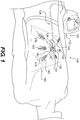
- Fig. 1 illustrates a wound treatment device 100, including a mechanical treatment device 110 and reduced pressure therapy device 120, according to the invention.
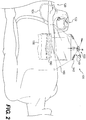
- Fig. 2 illustrates an expanded view of the device 100 of Fig. 1 , indicating how the components may be applied to a patient in certain embodiments.
- the mechanical treatment device 110 includes a first body 130 and two or more elongated sections 140 attached to and extending from the first body 130.
- the elongated sections 140 are configured to be attached to tissue around a wound or to a flexible sheet 160 overlying the wound and attached to tissue around the wound.
- the elongated sections 140 can be positioned to provide forces directed at pulling the wound margins together, and the forces can be controlled by adjusting the length of the elongated sections 140 using a tightening mechanism of the first body 130.
- the device 100 can include a reduced pressure therapy device 120.
- the reduced pressure therapy device 120 can include a pump 122 fluidly connected to the mechanical treatment device 110, e.g., through a fluid passage or tubing 124.
- the first body 130 of the mechanical treatment device 110 can include a fluid or suction connector 126 configured to be coupled with the fluid passage or tubing 124.
- the connector 126 can be fluidly coupled with the space underlying the first body 130, thereby providing suction or reduced pressure to the wound site.
- the first body 130 can provide a fluid connection between the fluid passage 124 and the wound site.
- the mechanical treatment device 110 is used to allow adjustable mechanical forces to be applied to tissue surrounding wounds, while allowing reduced pressure therapy to be administered.
- the mechanical treatment device 110 can provide tension to wound margins for a variety of different wound shapes and at various anatomical sites.
- the device 110 includes six elongated sections 140 extending on substantially opposite sides of an elongated, or substantially linear wound site 150 (labeled in Fig. 2 ).
- the elongated sections 140 can be formed from a flexible material, such as a wire, cord, or string, attached to a distal connector 142, which is configured to engage tissue (e.g., skin) or a flexible sheet 160 overlying the wound site 150.
- the elongated sections can be formed from elastic or flexible polymeric materials.
- Fig. 1 illustrates a mechanical treatment device 110 including six elongated sections 140, but the number of elongated sections 140 can be varied. In certain embodiments, the number of elongated sections 140 may relate to the intended use, the shape or size of the wound to be treated, and/or the anatomical site of the wound. In some embodiments, the mechanical treatment device 110 will include at least two elongated sections, at least three elongated sections, at least four elongated sections, at least five elongated sections, at least six elongated sections, at least seven elongated sections, or at least eight elongated sections. In various embodiments, any suitable number of elongated sections can be selected based on the specific wound to be treated.
- the orientation and/or length of the elongated sections 140 can be varied. In certain embodiments, the orientation and/or length is based on the specific wound to be treated. For example, as shown in Fig. 1 , three elongated sections are placed on each side of an elongated wound, thereby allowing the wound edges to be pulled towards one another. However, as few as two elongated sections 140 can be used, each being disposed on opposite sites of a wound to pull the wound margins towards one another.
- the orientation of each of the elongated sections 140 with respect to the first body 130 can be selected to control the direction and magnitude of the forces exerted on surrounding tissue.
- the flexible nature of the elongated sections 140 will allow a high degree of control so that a surgeon or other health care worker can treat wounds having a wide range of sizes and shapes.
- more elongated sections 140 may be used for more irregular or larger wounds, as described further below.
- the first body 130 and elongated sections 140 can include a variety of different structures and/or materials.
- the elongated sections 140 can include elongated, flexible wires or cords. These wires or cords can be formed from a variety of suitable materials, including, but not limited to, metals and/or synthetic or naturally occurring polymers.
- the elongated sections 140 can be braided, laminated, or of unitary structure.
- the specific material and dimensions can be selected based on the amount of force that may be applied to the elongated sections 140 and/or the degree of flexibility suitable for the selected anatomic site.
- the first body 130 (as well as the first bodies described below 230, 830, 930) can be produced from a rigid material, such as a rigid plastic or metal, that can withstand tension exerted by elongated extensions 140. In certain embodiments, part or all of the first body 130 can be softer or more pliable.
- the mechanical treatment device 110 can be configured to provide mechanical forces to assist in wound closure, while providing reduced pressure therapy.
- suitable reduced pressure therapy devices include V.A.C.® therapy devices produced by Kinetic Concepts, Inc (San Antonio, Texas).
- Such reduced pressure therapy devices can include a vacuum pump, similar to the pump 122 shown in Fig. 1 , which can be fluidly connected to the first body 130 of the mechanical treatment device 110.
- Such devices may also include a flexible sheet 160 to cover the wound site 150 and at least partially seal the wound to allow reduced pressure therapy to be provided at the wound site.
- such systems may include a porous material or dressing 180, that is placed at the wound site and facilitates wound closure, healing, tissue regeneration or repair, prevents or treats infection, and/or has other beneficial effects.
- the flexible sheet 160 will include a flexible polymeric material.
- any suitable polymeric material can be selected.
- the material does not cause significant irritation, immune response, or heightened risk of infection.
- the specific material generally should be of sufficient thickness and impermeability to allow reduced pressure therapy at a wound site under the sheet 160.
- the connectors 142 may be attached to the flexible sheet 160, while the flexible sheet 160 is attached to underlying skin or other tissue. Accordingly, in various embodiments, the mechanical forces generated by the mechanical treatment device 110 will be at least partially transmitted through the sheet 160, and therefore, the specific material thickness and physical properties will be selected to withstand such physical demands.
- the device 100 will include an adhesive.
- adhesive will be understood to refer to any substance that causes the surfaces of two objects to be attached to one another.
- suitable adhesives can include a variety of different cements, glues, resins, or other materials that can facilitate attachment of the flexible sheet 160 to tissue or to other components of the device 100.
- the adhesive can include a pressure-sensitive acrylic adhesive.
- the adhesives can be applied directly to the structures to be joined, or the adhesives may be applied on tape, or with other supporting substrate materials.
- the adhesive can be applied to a surface of the flexible sheet 160 to attach the sheet to skin or other tissue. In some embodiments, the adhesive will be applied to the surface of the sheet and packaged and/or distributed with the sheet 160. In some embodiments, the adhesive is applied to a surface of the sheet 160 and covered by a nonadhesive material that can be removed to expose the adhesive for use. In certain embodiments, the adhesive can be supplied as a separate component (e.g., in a container or on a tape) that is applied to the sheet 160 to attach the sheet 160 to tissue.
- the porous material 180 can include a variety of suitable materials.
- suitable materials for use with the above-noted V.A.C.® treatment systems.
- Such dressings can include, but are not limited to, porous open-cell foam structures, such as open-cell polyurethane.
- other materials containing various therapeutic substances can be selected for use with the devices of the present disclosure, and in various embodiments, the specific dressing may be selected based on the particular wound to be treated.
- the connectors 142 attached to the elongated sections 140 can be attached to skin or other tissue, or to the flexible sheet 160 covering a wound site 150 and dressing 180. Certain exemplary configurations for the connectors 142 are described in more detail below.
- the connectors 142 can be configured to attach to the flexible sheet, skin, or other tissue without penetrating the sheet, skin, or other tissue.
- an adhesive may be placed on an undersurface 516 of the connectors 142 to allow the connectors 142 to be attached to the sheet, skin, or other tissue without penetrating the skin.
- the adhesive can include the same adhesive selected to attach the flexible sheet 160 to the patient.
- the adhesive can include a pressure-sensitive acrylic adhesive.
- the adhesive can be a cyanoacrylate adhesive.
- the connectors 142 can have at least one dimension that is enlarged compared to the elongated sections 140. In some embodiments, the connectors 142 are wider than the elongated sections 140 to which they are attached. In certain embodiments, the connectors 142 have a larger surface area relative to their length to provide a larger surface of attachment.
- the method of attachment of the connectors 142 to the elongated sections 140 can be varied.
- the connectors 142 can be removably attached to the elongated sections 140.
- the connectors 142 can be permanently attached to the elongated sections 140.
- the connectors 142 can be formed from the same piece of material that forms the elongated sections 140.
- the connectors 142 can be formed from a different piece of material, but can be permanently attached with a weld, chemical bond, or adhesive attachment.
- the flexible sheet 160 can be attached over a wound site 150, with at least part of the mechanical treatment device 110 attached to a top surface of the flexible sheet 160.
- the wound is first cleaned and other preparatory procedures are performed.
- a porous material 180 or dressing is selected and cut to an appropriate size before being placed at the wound site 150.
- the flexible sheet 160 is attached over the wound site 150, with the edges of the sheet 160 overlying the wound margins a sufficient distance to allow a seal to be formed to perform reduced pressure therapy.
- the first body 130 of the mechanical treatment device 110 is attached to the sheet 160.
- the sheet 160 will include a preformed opening or fluid passage to allow the mechanical treatment devices to be attached.
- the first body 130 and sheet 160 may be produced and/or distributed as a single unit that is already assembled.
- a surgeon can use a sheet having no opening or preformed attachment for the first body 130, but may produce the opening and attach the first body 130 using an adhesive, such as that used to attach the connectors 142 and/or sheet 160.
- the sheet 160 can include a tubular member attached to the sheet 160 through a preformed passage, and the first body 130 can be configured to attach to this tubular member to provide fluid communication with an underlying wound.
- the connectors 142 can be positioned on the sheet 160.
- the connectors 142 may be attached to the sheet 160 using an adhesive to attach undersurfaces 516 of the connectors 142 to the sheet. Accordingly, with the sheet 160 being adhesively attached to the patient's skin or other tissue, and the mechanical treatment device 110 being attached to the sheet 160, forces generated in the elongated sections 140 are transmitted to the patient's tissue, thereby mechanically coupling the device 110 to the area surrounding the wound and drawing the wound margins closer together.
- the mechanical wound treatment device 110 can be attached directly to the skin or other tissue around a wound site to mechanically couple the device 110 to the tissue around the wound and draw the wound margins closer together.
- Fig. 3 illustrates certain embodiments of the wound treatment device 100 of Fig. 1 .
- the device 100 again includes a mechanical wound treatment device 110 having a number of elongated sections 140 extending in different directions from a first body 130.
- the first body 130 further includes a connector 126 configured to engage a reduced pressure therapy device 120, as described previously.
- the mechanical treatment device 110 is attached to tissue surrounding the wound site before the flexible sheet 160 is applied to seal the wound.
- the undersurfaces 516 of the connectors 142 are adhesively attached directly to skin or other tissue.
- the fluid passage or tubing 124 of the reduced pressure therapy device 120 can pass under the sheet 160.
- the fluid passage 124 and/or the first body 130 of the mechanical treatment device 110 can protrude through an opening (not shown) formed in the sheet 160, thereby allowing access to these elements when the sheet is applied.
- the sheet 160 may be sized such that when placed over the mechanical wound treatment device 110, the sheet will cover the first body 130, the elongated sections 140, and each of the connectors 142. In some embodiments, the sheet 160 covers the first body 130 and wound, while the connectors 142 are not covered by the sheet 160, but remain attached to tissue. In some embodiments, the sheet 160 will be sized so that one or more connectors 142 are not covered to allow easy manipulation of the connectors 142.
- the wound treatment devices of the present disclosure can be used to treat wounds having a variety of different types, shapes, sizes, and locations.
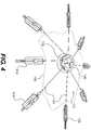
- Fig. 4 illustrates certain embodiments of the wound treatment device 100 of Fig. 1 , being used to treat a more irregularly shaped wound 155.
- Various elements in Fig. 1 that are not shown in Fig. 4 can be used with the embodiments in Fig. 4 .
- the mechanical treatment device 110 includes eight elongated sections 140 extending in various directions. Further, the positions of the connectors 142 with respect to the margins of the wound 155 have been adjusted to conform to the irregularities of the wound 155. Therefore, in various embodiments, the mechanical treatment devices provide flexibility in treating a variety of different shapes and sizes of wounds by allowing control of the number, length, and position of elongated sections that produce tensile forces to assist in tissue stretching and/or wound closure.
- the length and position of the elongated sections 140 and/or connectors 142 can be controlled in a number of other ways to allow the connectors 142 to be appropriately positioned around a wound.
- the length of the connectors 142 can be adjusted.
- the position at which the connectors 142 attach to the elongated sections 140 can be adjusted to control the distance from the first body 130 to the connectors 142.
- the connectors 142 can include an adjustable length, thereby allowing control of the distance from the first body 130 to the position of attachment of the connector 142 to the patient's tissue or the sheet 160.
- Figs. 5A-5B illustrate certain embodiments of an adjustable connector 142.
- Fig. 5A illustrates the adjustable connector in a more elongated configuration
- Fig. 5B illustrates the adjustable connector of Fig. 5A in a shortened configuration.
- the connector 142 includes a tab portion 504 having a series of notches or ridges 508 along its length. Further, a proximal end 505 of the tab portion 504 is attached to the elongated section 140.
- the connector 142 further includes a tab receiving portion 500 having an undersurface 516 that can be adhesively attached to a patient's tissue or a flexible sheet 160, as described above.
- the tab receiving portion 500 includes an opening and passage 510 configured to receive the tab portion 504. Further, as the tab portion 504 is advanced into the passage 510, the ridges or notches 508 will engage an inwardly protruding portion 514 of a locking mechanism 512, thereby securing the tab portion 504 within the tab receiving portion 500.
- the locking mechanism 512 prevents sliding movement of the tab portion 504 within the tab receiving portion 500 in one direction, while allowing sliding movement in the opposite direction. In some embodiments, the locking mechanism 512 allows the tab portion 504 to slide into the tab receiving portion 500, thereby shortening the distance from the tab receiving portion 500 to the end of the elongated section 140 attached to the tab portion 504, and prevents movement of the tab portion 504 out of the tab receiving portion 500, thereby preventing an increase in the distance from the tab receiving portion 500 and the end of the elongated section 140 attached to the tab portion 504 .
- the tab portion 504 can be advanced a desired distance within the tab receiving portion 500, thereby adjusting the distance between the tab receiving portion 500 and the end of the elongated section 140 attached to the tab portion 504, and controlling the overall length of the connector 142.
- the tab portion 504 can be advanced nearly completely to shorten the distance between the tab receiving portion 500 and the end of the elongated section 140 attached to the tab portion 504.
- the distance between the tab receiving portion 500 and the end of the elongated section 140 attached to the tab portion 504 can be increased.
- the length of the connectors 142 can be adjusted either before the connectors 142 are attached to a patient's tissue or a sheet 160 or after the connectors 142 are attached to the patient's tissue or sheet 160.
- the tab receiving portion 500 is attached to tissue or a sheet 160, and then the tab portion 504 is inserted or adjusted within the tab receiving portion 500 to produce increased tension in the elongated section 140 attached to the tab portion 504.
- the tab portion 504 is adjusted to a selected position within the tab receiving portion 500, and then the tab receiving portion 500 is attached to tissue or the sheet 160.
- the distance of the connectors from the first body 130 can be controlled by adjusting the position of the connectors along the elongated section 140.
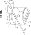
- Figs. 6A-6B illustrate an adjustable connector 600 and an elongated section 140 of a wound treatment device, according to certain exemplary embodiments.
- the connector 600 is adjustably positioned along the length of the elongated section 140.
- the connector 600 includes a connector main body 604 and a locking body 608.
- the locking body 608 includes an opening 612 for receiving the elongated section 140
- the connector main body 604 includes a groove 620 for receiving the elongated section 140.
- a cover 630 is attached to the top of the main body 604 to cover the groove 620.
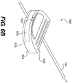
- the connector 600 can be adjusted along the length of the elongated section 140. Then, in order to lock the connector 600 in place, the locking body 608, with the elongated section 140 passing through the groove 620 and opening 612, is pushed into a slot 610 of the connector main body 610, thereby applying pressure to the elongated section 140 to crimp the elongated section 140 and secure the connector 600 in place along the elongated section 140.
- the locking body 608 and slot 610 can be sized such that a press fit connection is formed upon inserting the locking body 608 into the slot 610, along with the elongated section 140. In some embodiments, the pressure formed by this connection will be sufficient to hold the connector 600 in place on the elongated section 140. In some embodiments, an adhesive or other connection mechanism may be used to secure the locking body 608 within the slot 610.
- the connector 600 can be attached to a patient's tissue or a sheet 160 using an adhesive.
- an adhesive can be applied to, or exposed on (e.g., on a surface of two-way tape), a bottom surface 616 of the connector 600 or a tissue or sheet surface to which the connector 600 is to be attached.
- the mechanical treatment device can be tightened to produce a desired degree of tension in the tissue surrounding the wound.
- the first body 130 can include a number of mechanisms to facilitate tightening of the elongated sections 140 to produce the desired amount of tension in the surrounding tissue.
- the first body 130 can include a rotatable portion for shortening the elongated sections 140, thereby increasing tension and/or stretching surrounding tissue.
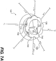
- Fig. 7A illustrates an enlarged view of the first body 130, according to certain exemplary embodiments
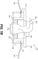
- Fig. 7B illustrates a partial cutaway view of the first body 130 of Fig. 7A
- the elongated sections 140 extend from the first body 130 in various directions. Further, as noted previously, in various embodiments, the number and position of each elongated section 140 can vary or be adjusted based on the particular wound to be treated.
- the first body 130 includes a rotatable portion 700.
- the rotatable portion 700 is operably engaged with an internal wall 720 (shown in Fig. 7B ) to which the elongated sections 140 are attached.
- the internal wall 720 has a substantially cylindrical shape, and the elongated sections 140 are attached to the surface of the internal wall 720. Therefore, as the rotatable portion 700 is rotated, the internal wall 720 rotates. As the internal wall 720 rotates, the elongated sections 140, which are attached to the internal wall 720, are at least partially wrapped around the internal wall 720.
- wrapping of the elongated sections 140 around the internal wall 720 causes the distance that the elongated sections 140 extend from the first body 130 to be decreased to produce a desired tension in tissue attached to the connectors 142 or the sheet 160, as described above.
- rotation of the rotatable portion 700 in one direction decreases the distance that the elongated sections 140 extend from the first body 130.
- rotation of the rotatable portion 700 in a second direction opposite the first direction increases the distance the elongated sections 140 extend from the first body 130.
- the first body 130 can further include a locking mechanism 730 operably engaged with the inner wall 720 and/or rotatable portion 700.
- the locking mechanism 730 can be configured to allow rotation or tightening in one direction but not the other, thereby allowing tightening by twisting the rotatable portion 700, and preventing loosening by preventing counter rotation.
- the locking mechanism 730 can include a ratchet mechanism or a ratchet and pawl, as are known in the art.
- the ratchet mechanism can be reversible to allow tightening and loosening when desired.
- the first body 130 can include a release mechanism 735.
- the release mechanism 735 can include a button or switch that can control operation of the locking mechanism 730 to engage, disengage, or reverse direction of the locking mechanism 730.
- the release mechanism 735 can reverse the direction of operation of the locking mechanism 730 to allow rotation in a first direction but not a second direction, or to allow rotation in the second direction but not the first direction.
- the release mechanism 735 can disengage the locking mechanism 730 to allow rotation in either direction.
- the first body 130 can further include an outer wall 708 having openings 710 through which the elongated sections 140 can pass before attaching to the inner wall 720.
- these openings can have a fixed position about the periphery of the first body 130. In some embodiments, the openings does not move as the rotatable portion 700 is moved, thereby controlling the direction along which the elongated sections 140 exert force on surrounding tissue, even as the elongated sections 140 are tightened.
- the wound treatment devices 100 can allow mechanical treatment in conjunction with reduced pressure therapy.
- the first body 130 further includes a connector 126 configured to engage the fluid passage 124 of a reduced therapy system pump 122.
- the connector 126 includes an opening 128 that can be fluidly connected with the fluid passage 124.
- the opening 128 is in fluid communication with a fluid passage 129 that passes through the first body 130 and is in fluid communication with a wound and dressing to provide reduced pressure therapy.
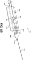
- Fig. 8A illustrates a wound treatment device 200, according to certain exemplary embodiments.
- the device 200 includes a mechanical treatment device 210, also including a first body 230, similar to first body 130.
- the device 210 includes a number of elongated sections 140 extending at various directions and being attached to a sheet 160 overlying and sealing a wound to be treated.
- the elongated sections 140 are attached to the sheet using connectors 600, as described with respect to Figs. 6A and 6B .
- any of the connectors described herein may be used.
- Fig. 8B illustrates a partial cut-away view of the device of Fig. 8A , showing internal components of the device.
- the first body 230 includes a rotatable portion 250 attached to a spool or tightening mechanism 240.
- Each of the elongated sections 140 are attached to the spool or tightening mechanism, so that as the rotatable portion 250 is rotated, the tightening mechanism is engaged to increase tension in the elongated sections 140, thereby pulling wound margins mechanically coupled to the connectors 600 closer together.
- the device 200 can include an internal locking mechanism, such as a ratchet system that allows rotation in one direction, while preventing counter rotation.
- the spool or tightening mechanism 240 can include a series of gears to provide a mechanical advantage, allowing increased tension to be produced in the elongated sections 140 without excessive effort directed at turning the rotatable portion 250.
- the first body 230 can be configured to facilitate mechanical wound closure, while allowing reduced pressure therapy. Accordingly, in certain embodiments, the first body 230 can include a fluid connector 226 that can be fluidly coupled with a pump 122 via a fluid passage 124. The fluid connector 226 can include an opening 228 and can communicate with a fluid passage 229 traversing the first body 230 to provide fluid communication with a wound.
- Fig. 9 illustrates an exemplary embodiment of a wound treatment device 900, not forming part of the invention.
- the device 900 includes a first body 930 having two or more elongated sections 940 extending from the first body 930 and including connectors 942 configured to be adhesively attached to a patient's tissue or a flexible sheet 160 (not shown) using at surfaces 916.
- the device 900 includes a connector 926 configured to engage a reduced pressure therapy device 120, as described previously.
- each of the elongated sections 940 are adjustably connected to the first body 930 at elongated section receiving portions 946.
- proximal end portions 950 of the elongated sections 940 are passed through the elongated section receiving portions 946, which, in some embodiments, include a female connector opening configured to receive a corresponding proximal end portion 950 forming a male connector portion of the elongated sections 940.
- the end portions 950 can be pulled further through the attachment regions 946 to shorten the length of each elongated section 940 extending from the first body 930 to produce the desired tension in each elongated section 940.
- the end portion 950 may be removed or cut off to reduce the device size and allow placement of an overlying sheet, if desired.
- the elongated sections 940 can include small ridges or notches 908 to allow the elongated sections 940 to be pulled through the elongated section receiving portions 946, and provide a locking mechanism that prevents the elongated sections 940 from being pulled back out of the openings after tightening.
- the specific locking mechanism can be selected based on the desired degree of tension to be produced, but one suitable mechanism is similar to that used in devices conventionally described as plastic handcuffs or ties.
- the wound treatment devices can be used for wounds having linear or irregular shapes.
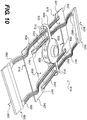
- Fig. 10 illustrates a mechanical wound treatment device 810 for use with substantially linear wounds, not forming part of the invention
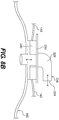
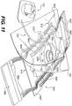
- Fig. 11 illustrates the wound treatment device of Fig. 10 , along with a reduced pressure treatment device.
- the device 810 includes a first body 830. Two pairs of elongated sections 840, 840' extend from the first body 830. In certain embodiments, each of the elongated sections 840, 840' includes a pair of substantially parallel elongated arms.
- a connector 842, 842' extends between first end regions 841, 841' of each pair of elongated arms of the elongated sections 840, 840', forming a flattened or enlarged region that can be attached to a patient's skin or other tissue, or to a sheet 160 overlying a wound.
- Each of the arms of the elongated sections 840, 840' can pass through openings 812 in the first body 830 and will extend to second ends 882, 882' of the elongated arms on opposite sides of the first body 830 from the connectors 842, 842'.
- handle regions 880, 880' extend between the second end regions 882, 882' of each of the pair of elongated arms.
- the connectors 842, 842' may be attached to tissue or a sheet around a wound site.
- the connectors 842, 842' can be attached using an adhesive, as described previously, thereby allowing force to be exerted on tissues surrounding the wound without penetrating skin or other tissue.
- the connectors 842, 842' can be pulled together to exert forces that assist in closing the wound or approximating wound edges.
- This force can be produced by pulling the handle regions 880, 880' apart in the direction 860, 860' indicated in Fig. 10 , thereby drawing the connectors 842, 842' together in the direction 864, 864' indicated in Fig. 10 .
- the first body 830 and elongated sections 840, 840' can include a locking mechanism.
- the elongated sections 840, 840' can include ridges or notches 808 along at least one of their surfaces, and the first body 830 can include an inner mechanism that prevents movement of elongated sections 842, 842' in one or both directions.
- the first body 830 can include additional openings 828 to receive elongated sections.
- the additional openings 828 can be positioned to allow the elongated sections 840, 840' to be positioned at different positions along the length of the first body 830.
- the openings 812 and additional openings 828 can be configured to receive elongated sections having other configurations.
- the elongated sections 940 (as shown in Fig. 9 ) can be used with the first body 830 shown in Fig. 10 .
- two or more of the elongated sections 940 will attached to the first body 830 so that elongated sections 940 extend in opposite directions from the first body 830.
- multiple elongated sections 940 will extend from the first body 830 to provide mechanical forces along the length of a linear wound.
- the mechanical treatment devices of the present disclosure can be designed to facilitate mechanical treatment to assist in wound closure, while allowing reduced pressure therapy.
- the device 810 can include a fluid connector 826 configured to connect to a fluid passage 124 of a reduced pressure therapy device, as shown in Fig. 11 .
- the fluid connector 826 can be fluidly connected with fluid passages that transverse the first body 830, providing fluid communication with a wound site underlying the device 810.
- the fluid connector 826 can be connected to a fluid passage passing downward to a bottom surface of the first body 830.
- the fluid passages may be positioned along the side or at other positions along the first body 830.
- one or more of the openings 828 can form fluid passages in fluid communication with the fluid connector 826.
- a sheet 160 can be placed over the apparatus 800 to seal the wound and allow both mechanical treatment and reduced pressure therapy.
- the sheet can include an opening 162 to allow the fluid connector 826 to pass through the sheet.
- the sheet 160 may be positioned under the mechanical treatment device 800, and the device can be adhesively attached to the sheet 160 to transmit mechanical forces to tissues located beneath the sheet 160.
- the elongated sections 840, 840' and connectors 842, 842' can be formed of a flexible material, as shown.
- a more rigid design may be selected based on the particular anatomic site and wound to be treated.
- the devices of the present disclosure can be used to treat wounds at numerous different anatomical sites. Further, although the devices are shown with one size, in various embodiments, the devices can be scaled based on the particular patient and anatomic site to be treated. In addition, although the devices are described for use with reduced pressure therapy, in various embodiments, the mechanical treatment devices of the present disclosure may be used alone, or without reduced pressure therapy systems, especially where it is desired to provide mechanical assistance for wound closure without penetrating skin or other tissue.
Landscapes
- Health & Medical Sciences (AREA)
- Life Sciences & Earth Sciences (AREA)
- Heart & Thoracic Surgery (AREA)
- General Health & Medical Sciences (AREA)
- Veterinary Medicine (AREA)
- Biomedical Technology (AREA)
- Engineering & Computer Science (AREA)
- Animal Behavior & Ethology (AREA)
- Public Health (AREA)
- Surgery (AREA)
- Hematology (AREA)
- Anesthesiology (AREA)
- Molecular Biology (AREA)
- Nuclear Medicine, Radiotherapy & Molecular Imaging (AREA)
- Medical Informatics (AREA)
- Vascular Medicine (AREA)
- Otolaryngology (AREA)
- Surgical Instruments (AREA)
- Media Introduction/Drainage Providing Device (AREA)
- Pharmaceuticals Containing Other Organic And Inorganic Compounds (AREA)
Description
- The present disclosure pertains to devices for wound treatment, and particularly, to devices that allow mechanical force and reduced pressure therapy.
- Reduced pressure, or vacuum-assisted, therapies can be effective for improving wound healing due to a variety of different causes and at a number of different anatomical locations. Typically, reduced pressure therapies include a porous material that is placed at a wound site. A membrane or drape is placed over the porous material to provide an airtight seal at the wound area, and a negative pressure is applied to the porous material to provide a reduced pressure at the wound site.
- Tissue stretching systems can assist with wound closure. Such stretching systems may provide mechanical forces to tissue around the wound to allow approximation of the wound margins over time.
-
WO 2007/092397A2 discloses a system for improved connection to wound dressings in conjunction with reduced pressure wound treatment systems. -
US 2006/0058842 A1 discloses a wound closure product which includes a plurality of skin anchors and a line. - Claim 1 defines the invention and the dependent claims disclose the preferred embodiments. According to certain embodiments, a wound treatment device is provided that comprises a first body comprising at least one first opening configured for attachment to a reduced pressure source and at least one fluid passage extending at least partially through the first body and in fluid communication with the at least one opening. The device further comprises two or more elongated sections,
each attached to the first body, extending from the first body in different directions, and having a length that is adjustable with respect to the first body. - An exemplary method for treating a wound is provided that comprises mechanically coupling two or more elongated sections to tissue at two or more locations around a wound, the two or more elongated sections being attached to a first body comprising at least one first opening configured for attachment to a reduced pressure source and at least one fluid passage extending at least partially through the first body and in fluid communication with the at least one opening. The method further comprises creating tension in the two or more elongated sections to pull the tissue at the two or more locations around the wound closer together.
- According to certain embodiments, a wound treatment device is provided that comprises a first body having a substantially rigid material body. The device further comprises two or more elongated sections, each attached to the first body, extending from the first body in different directions, and having a length that is adjustable with respect to the first body. The device also comprises an adhesive for mechanically coupling two or more connectors, each attached to one of the two or more elongated sections, to tissue surrounding a wound.
- An exemplary method for treating a wound is provided that comprises mechanically coupling two or more elongated sections to tissue at two or more locations around a wound using an adhesive, the two or more elongated sections being attached to a first material body. The method further comprises creating tension in the two or more elongated sections to pull the tissue at the two or more locations around the wound closer together.
-
-
Fig. 1 illustrates a wound treatment device, which provides mechanical force and reduced pressure therapy, according to certain exemplary embodiments. -
Fig. 2 illustrates an exploded view of the device ofFig. 1 . -
Fig. 3 illustrates another embodiment of the wound treatment device ofFig. 1 . -
Fig. 4 illustrates certain exemplary embodiments of the wound treatment device ofFig. 1 , which includes additional elongated sections. -
Fig. 5A illustrates an adjustable connector attached to an elongated section of a mechanical wound treatment device, according to certain exemplary embodiments. -
Fig. 5B illustrates the adjustable connector ofFig. 5A in a shortened position. -
Fig. 6A illustrates another adjustable connector attached to an elongated section of a wound treatment device, according to certain exemplary embodiments. -
Fig. 6B illustrates the adjustable connector ofFig. 6A in a closed and fixed position on the elongated section. -
Fig. 7A illustrates an enlarged view of a first body of a wound treatment device, including a tightening or tension-producing mechanism, according to certain exemplary embodiments. -
Fig. 7B illustrates a partial cut-away view of the device ofFig. 7A , showing internal components of the device. -
Fig. 8A illustrates a wound treatment device according to certain exemplary embodiments. -
Fig. 8B illustrates a partial cut-away view of the device ofFig. 8A , showing internal components of the device. -
Fig. 9 illustrates an exemplary wound treatment device. -
Fig. 10 illustrates an exemplary wound treatment device. -
Fig. 11 illustrates the wound treatment device ofFig. 10 , including reduced pressure therapy treatment components. - Reference will now be made in detail to the certain exemplary embodiments according to the present disclosure, certain examples of which are illustrated in the accompanying drawings. Wherever possible, the same reference numbers will be used throughout the drawings to refer to the same or like parts.
- The present disclosure pertains to wound treatment devices that can be used to provide mechanical forces to assist in closing, or at least partially closing, wounds. In some embodiments, the devices of the present disclosure can be configured to provide mechanical forces directed at approximating wound margins without damaging surrounding skin or other tissue. In some embodiments, the mechanical forces are applied without penetrating skin or other tissue. In certain embodiments, the devices provide mechanical forces directed at approximating wound margins in conjunction with reduced pressure therapy. In various embodiments, the devices can be used to treat a variety of different wound shapes and at many different anatomical locations.
- In this application, the use of the singular includes the plural unless specifically stated otherwise. In this application, the use of "or" means "and/or" unless stated otherwise. Furthermore, the use of the term "including", as well as other forms, such as "includes" and "included", is not limiting. Also, terms such as "element" or "component" encompass both elements and components comprising one unit and elements and components that comprise more than one subunit, unless specifically stated otherwise. Also the use of the term "portion" may include part of a moiety or the entire moiety.
- The section headings used herein are for organizational purposes only and are not to be construed as limiting the subject matter described.
- The term "reduced pressure," as used herein, generally refers to a pressure less than the ambient pressure at a tissue site that is being subjected to treatment. In most cases, this reduced pressure will be less than the atmospheric pressure at which the patient is located. Alternatively, the reduced pressure may be less than a hydrostatic pressure of tissue at the tissue site. Reduced pressure may initially generate fluid flow in the tube and the area of the tissue site. As the hydrostatic pressure around the tissue site approaches the desired reduced pressure, the flow may subside, and the reduced pressure is then maintained. Unless otherwise indicated, values of pressure stated herein are gage pressures.
- The term "fluid" as used herein generally refers to a gas or liquid, but may also include any other flowable material, including but not limited to gels, colloids, and foams.
- Although reduced pressure therapy is effective to improve healing times and reduce complications for many types of wounds, in some cases, additional therapies may help improve results. For example, for larger wounds, there may be insufficient overlying dermal, epidermal, and/or subcutaneous tissue to cover the entire wound. In such cases, skin grafts or other reconstructive procedures may be used to cover the wound. Devices described herein can be used to provide mechanical forces and reduced pressure therapy to assist in wound closure, resulting in wound closure and healing without grafting or other reconstructive procedures. Devices described herein can be used to provide mechanical forces and reduced pressure therapy to assist in wound closure, and may be used before, simultaneously with, and/or after grafting or other procedures or therapies.
- The devices described herein can be used to assist in treating wounds caused by trauma due to injury and/or surgery. In addition, some surgical wounds are closed using delayed primary closure or closure by secondary approximation. Devices described herein can be used to provide mechanical forces and reduced pressure therapy to assist in wound closure by delayed primary closure or by secondary approximation. Further, certain wounds are caused by diseases such as diabetes or vascular disease, and may not be due to surgery or trauma. The devices described herein may be used to assist in healing of wounds caused by any disease.
- Many mechanical wound closure systems include sharp hooks or barbs to grasp the tissue adjacent to the wound. These hooks and barbs may be effective for short-term application of mechanical forces to the surrounding tissues, but, when used over more extended times, can cause the adjacent tissue to break down. In certain embodiments, the devices described herein are able to attach to tissue without hooks or barbs.
- In addition, prior mechanical wound closure devices are not compatible for use with reduced pressure therapy devices. The devices described herein are compatible with reduced pressure therapy. In certain embodiments, the devices disclosed herein allow for periodic replacement of the porous material or other procedures used in reduced pressure therapy.
-
Fig. 1 illustrates awound treatment device 100, including amechanical treatment device 110 and reducedpressure therapy device 120, according to the invention. andFig. 2 illustrates an expanded view of thedevice 100 ofFig. 1 , indicating how the components may be applied to a patient in certain embodiments. As shown and described in more detail below, themechanical treatment device 110 includes afirst body 130 and two or moreelongated sections 140 attached to and extending from thefirst body 130. Theelongated sections 140 are configured to be attached to tissue around a wound or to aflexible sheet 160 overlying the wound and attached to tissue around the wound. Theelongated sections 140 can be positioned to provide forces directed at pulling the wound margins together, and the forces can be controlled by adjusting the length of theelongated sections 140 using a tightening mechanism of thefirst body 130. - Further, in some embodiments, the
device 100 can include a reducedpressure therapy device 120. As shown, the reducedpressure therapy device 120 can include apump 122 fluidly connected to themechanical treatment device 110, e.g., through a fluid passage ortubing 124. In some embodiments, thefirst body 130 of themechanical treatment device 110 can include a fluid orsuction connector 126 configured to be coupled with the fluid passage ortubing 124. Theconnector 126 can be fluidly coupled with the space underlying thefirst body 130, thereby providing suction or reduced pressure to the wound site. Accordingly, thefirst body 130 can provide a fluid connection between thefluid passage 124 and the wound site. According to the invention, themechanical treatment device 110 is used to allow adjustable mechanical forces to be applied to tissue surrounding wounds, while allowing reduced pressure therapy to be administered. - The
mechanical treatment device 110 can provide tension to wound margins for a variety of different wound shapes and at various anatomical sites. For example, as shown inFigs. 1 and2 , thedevice 110 includes sixelongated sections 140 extending on substantially opposite sides of an elongated, or substantially linear wound site 150 (labeled inFig. 2 ). As shown inFigs. 1 and2 , theelongated sections 140 can be formed from a flexible material, such as a wire, cord, or string, attached to adistal connector 142, which is configured to engage tissue (e.g., skin) or aflexible sheet 160 overlying thewound site 150. In some embodiments, the elongated sections can be formed from elastic or flexible polymeric materials. - As noted,
Fig. 1 illustrates amechanical treatment device 110 including sixelongated sections 140, but the number ofelongated sections 140 can be varied. In certain embodiments, the number ofelongated sections 140 may relate to the intended use, the shape or size of the wound to be treated, and/or the anatomical site of the wound. In some embodiments, themechanical treatment device 110 will include at least two elongated sections, at least three elongated sections, at least four elongated sections, at least five elongated sections, at least six elongated sections, at least seven elongated sections, or at least eight elongated sections. In various embodiments, any suitable number of elongated sections can be selected based on the specific wound to be treated. - In addition, in various embodiments, the orientation and/or length of the
elongated sections 140 can be varied. In certain embodiments, the orientation and/or length is based on the specific wound to be treated. For example, as shown inFig. 1 , three elongated sections are placed on each side of an elongated wound, thereby allowing the wound edges to be pulled towards one another. However, as few as twoelongated sections 140 can be used, each being disposed on opposite sites of a wound to pull the wound margins towards one another. - In certain embodiments, for more round and/or irregular wounds, the orientation of each of the
elongated sections 140 with respect to thefirst body 130 can be selected to control the direction and magnitude of the forces exerted on surrounding tissue. Further, in certain embodiments, the flexible nature of theelongated sections 140 will allow a high degree of control so that a surgeon or other health care worker can treat wounds having a wide range of sizes and shapes. In addition, in various embodiments, moreelongated sections 140 may be used for more irregular or larger wounds, as described further below. - In various embodiments, the
first body 130 andelongated sections 140 can include a variety of different structures and/or materials. For example, as shown, theelongated sections 140 can include elongated, flexible wires or cords. These wires or cords can be formed from a variety of suitable materials, including, but not limited to, metals and/or synthetic or naturally occurring polymers. In various embodiments, theelongated sections 140, can be braided, laminated, or of unitary structure. In various embodiments, the specific material and dimensions can be selected based on the amount of force that may be applied to theelongated sections 140 and/or the degree of flexibility suitable for the selected anatomic site. In some embodiments, the first body 130 (as well as the first bodies described below 230, 830, 930) can be produced from a rigid material, such as a rigid plastic or metal, that can withstand tension exerted byelongated extensions 140. In certain embodiments, part or all of thefirst body 130 can be softer or more pliable. - As noted, the
mechanical treatment device 110 can be configured to provide mechanical forces to assist in wound closure, while providing reduced pressure therapy. In various embodiments, a variety of reduced pressure therapy devices can be used. For example, suitable reduced pressure therapy devices include V.A.C.® therapy devices produced by Kinetic Concepts, Inc (San Antonio, Texas). Such reduced pressure therapy devices can include a vacuum pump, similar to thepump 122 shown inFig. 1 , which can be fluidly connected to thefirst body 130 of themechanical treatment device 110. Such devices may also include aflexible sheet 160 to cover thewound site 150 and at least partially seal the wound to allow reduced pressure therapy to be provided at the wound site. In addition, such systems may include a porous material or dressing 180, that is placed at the wound site and facilitates wound closure, healing, tissue regeneration or repair, prevents or treats infection, and/or has other beneficial effects. - In some embodiments, the
flexible sheet 160 will include a flexible polymeric material. In various embodiments, any suitable polymeric material can be selected. In various embodiments, the material does not cause significant irritation, immune response, or heightened risk of infection. In various embodiments, the specific material generally should be of sufficient thickness and impermeability to allow reduced pressure therapy at a wound site under thesheet 160. In some embodiments, theconnectors 142 may be attached to theflexible sheet 160, while theflexible sheet 160 is attached to underlying skin or other tissue. Accordingly, in various embodiments, the mechanical forces generated by themechanical treatment device 110 will be at least partially transmitted through thesheet 160, and therefore, the specific material thickness and physical properties will be selected to withstand such physical demands. - In some embodiments, the
device 100 will include an adhesive. As used here, and throughout the disclosure, adhesive will be understood to refer to any substance that causes the surfaces of two objects to be attached to one another. In various embodiments, suitable adhesives can include a variety of different cements, glues, resins, or other materials that can facilitate attachment of theflexible sheet 160 to tissue or to other components of thedevice 100. In some embodiments, the adhesive can include a pressure-sensitive acrylic adhesive. In various embodiments, the adhesives can be applied directly to the structures to be joined, or the adhesives may be applied on tape, or with other supporting substrate materials. - In some embodiments, the adhesive can be applied to a surface of the
flexible sheet 160 to attach the sheet to skin or other tissue. In some embodiments, the adhesive will be applied to the surface of the sheet and packaged and/or distributed with thesheet 160. In some embodiments, the adhesive is applied to a surface of thesheet 160 and covered by a nonadhesive material that can be removed to expose the adhesive for use. In certain embodiments, the adhesive can be supplied as a separate component (e.g., in a container or on a tape) that is applied to thesheet 160 to attach thesheet 160 to tissue. - In various embodiments, the
porous material 180 can include a variety of suitable materials. For example, a number of different dressing materials are available for use with the above-noted V.A.C.® treatment systems. Such dressings can include, but are not limited to, porous open-cell foam structures, such as open-cell polyurethane. In various embodiments, other materials containing various therapeutic substances can be selected for use with the devices of the present disclosure, and in various embodiments, the specific dressing may be selected based on the particular wound to be treated. - As noted previously, in some embodiments, the
connectors 142 attached to theelongated sections 140 can be attached to skin or other tissue, or to theflexible sheet 160 covering awound site 150 and dressing 180. Certain exemplary configurations for theconnectors 142 are described in more detail below. In some embodiments, theconnectors 142 can be configured to attach to the flexible sheet, skin, or other tissue without penetrating the sheet, skin, or other tissue. For example, in some embodiments, an adhesive may be placed on anundersurface 516 of theconnectors 142 to allow theconnectors 142 to be attached to the sheet, skin, or other tissue without penetrating the skin. In some embodiments, the adhesive can include the same adhesive selected to attach theflexible sheet 160 to the patient. In some embodiments, the adhesive can include a pressure-sensitive acrylic adhesive. In some embodiments, the adhesive can be a cyanoacrylate adhesive. - In some embodiments, the
connectors 142 can have at least one dimension that is enlarged compared to theelongated sections 140. In some embodiments, theconnectors 142 are wider than theelongated sections 140 to which they are attached. In certain embodiments, theconnectors 142 have a larger surface area relative to their length to provide a larger surface of attachment. - In various embodiments, the method of attachment of the
connectors 142 to theelongated sections 140 can be varied. In certain embodiments, theconnectors 142 can be removably attached to theelongated sections 140. In other embodiments, theconnectors 142 can be permanently attached to theelongated sections 140. In some embodiments, theconnectors 142 can be formed from the same piece of material that forms theelongated sections 140. In certain embodiments, theconnectors 142 can be formed from a different piece of material, but can be permanently attached with a weld, chemical bond, or adhesive attachment. - In some embodiments, as shown in
Fig. 2 , theflexible sheet 160 can be attached over awound site 150, with at least part of themechanical treatment device 110 attached to a top surface of theflexible sheet 160. In an exemplary proceedure, the wound is first cleaned and other preparatory procedures are performed. Next, after preparing the wound, aporous material 180 or dressing is selected and cut to an appropriate size before being placed at thewound site 150. Then, after the dressing is positioned in the wound, theflexible sheet 160 is attached over thewound site 150, with the edges of thesheet 160 overlying the wound margins a sufficient distance to allow a seal to be formed to perform reduced pressure therapy. - After the dressing and sheet are positioned over the wound, the
first body 130 of themechanical treatment device 110 is attached to thesheet 160. In some embodiments, thesheet 160 will include a preformed opening or fluid passage to allow the mechanical treatment devices to be attached. In some embodiments, thefirst body 130 andsheet 160 may be produced and/or distributed as a single unit that is already assembled. In some embodiments, a surgeon can use a sheet having no opening or preformed attachment for thefirst body 130, but may produce the opening and attach thefirst body 130 using an adhesive, such as that used to attach theconnectors 142 and/orsheet 160. In some embodiments, thesheet 160 can include a tubular member attached to thesheet 160 through a preformed passage, and thefirst body 130 can be configured to attach to this tubular member to provide fluid communication with an underlying wound. - After the
first body 130 is attached to thesheet 160, theconnectors 142 can be positioned on thesheet 160. As noted previously, theconnectors 142 may be attached to thesheet 160 using an adhesive to attachundersurfaces 516 of theconnectors 142 to the sheet. Accordingly, with thesheet 160 being adhesively attached to the patient's skin or other tissue, and themechanical treatment device 110 being attached to thesheet 160, forces generated in theelongated sections 140 are transmitted to the patient's tissue, thereby mechanically coupling thedevice 110 to the area surrounding the wound and drawing the wound margins closer together. - In certain embodiments, the mechanical
wound treatment device 110 can be attached directly to the skin or other tissue around a wound site to mechanically couple thedevice 110 to the tissue around the wound and draw the wound margins closer together. For example,Fig. 3 illustrates certain embodiments of thewound treatment device 100 ofFig. 1 . As shown, thedevice 100 again includes a mechanicalwound treatment device 110 having a number ofelongated sections 140 extending in different directions from afirst body 130. Thefirst body 130 further includes aconnector 126 configured to engage a reducedpressure therapy device 120, as described previously. However, in such embodiments, themechanical treatment device 110 is attached to tissue surrounding the wound site before theflexible sheet 160 is applied to seal the wound. Therefore, theundersurfaces 516 of theconnectors 142 are adhesively attached directly to skin or other tissue. Further, the fluid passage ortubing 124 of the reducedpressure therapy device 120 can pass under thesheet 160. Alternatively, in various embodiments, thefluid passage 124 and/or thefirst body 130 of themechanical treatment device 110 can protrude through an opening (not shown) formed in thesheet 160, thereby allowing access to these elements when the sheet is applied. - As shown in
Fig. 3 , in some embodiments, thesheet 160 may be sized such that when placed over the mechanicalwound treatment device 110, the sheet will cover thefirst body 130, theelongated sections 140, and each of theconnectors 142. In some embodiments, thesheet 160 covers thefirst body 130 and wound, while theconnectors 142 are not covered by thesheet 160, but remain attached to tissue. In some embodiments, thesheet 160 will be sized so that one ormore connectors 142 are not covered to allow easy manipulation of theconnectors 142. - As noted previously, in various embodiments, the wound treatment devices of the present disclosure can be used to treat wounds having a variety of different types, shapes, sizes, and locations. For example,
Fig. 4 illustrates certain embodiments of thewound treatment device 100 ofFig. 1 , being used to treat a more irregularly shapedwound 155. Various elements inFig. 1 that are not shown inFig. 4 can be used with the embodiments inFig. 4 . - As shown in
Fig. 4 , themechanical treatment device 110 includes eightelongated sections 140 extending in various directions. Further, the positions of theconnectors 142 with respect to the margins of thewound 155 have been adjusted to conform to the irregularities of thewound 155. Therefore, in various embodiments, the mechanical treatment devices provide flexibility in treating a variety of different shapes and sizes of wounds by allowing control of the number, length, and position of elongated sections that produce tensile forces to assist in tissue stretching and/or wound closure. - In addition to adjusting positions of the
connectors 142 by moving theelongated sections 140, the length and position of theelongated sections 140 and/orconnectors 142 can be controlled in a number of other ways to allow theconnectors 142 to be appropriately positioned around a wound. For example, in some embodiments, the length of theconnectors 142 can be adjusted. In other embodiments, the position at which theconnectors 142 attach to theelongated sections 140 can be adjusted to control the distance from thefirst body 130 to theconnectors 142. - In some embodiments, the
connectors 142 can include an adjustable length, thereby allowing control of the distance from thefirst body 130 to the position of attachment of theconnector 142 to the patient's tissue or thesheet 160.Figs. 5A-5B illustrate certain embodiments of anadjustable connector 142.Fig. 5A illustrates the adjustable connector in a more elongated configuration, andFig. 5B illustrates the adjustable connector ofFig. 5A in a shortened configuration. - As shown, the
connector 142 includes atab portion 504 having a series of notches orridges 508 along its length. Further, aproximal end 505 of thetab portion 504 is attached to theelongated section 140. Theconnector 142 further includes atab receiving portion 500 having anundersurface 516 that can be adhesively attached to a patient's tissue or aflexible sheet 160, as described above. As shown, thetab receiving portion 500 includes an opening andpassage 510 configured to receive thetab portion 504. Further, as thetab portion 504 is advanced into thepassage 510, the ridges ornotches 508 will engage an inwardly protrudingportion 514 of alocking mechanism 512, thereby securing thetab portion 504 within thetab receiving portion 500. In some embodiments, thelocking mechanism 512 prevents sliding movement of thetab portion 504 within thetab receiving portion 500 in one direction, while allowing sliding movement in the opposite direction. In some embodiments, thelocking mechanism 512 allows thetab portion 504 to slide into thetab receiving portion 500, thereby shortening the distance from thetab receiving portion 500 to the end of theelongated section 140 attached to thetab portion 504, and prevents movement of thetab portion 504 out of thetab receiving portion 500, thereby preventing an increase in the distance from thetab receiving portion 500 and the end of theelongated section 140 attached to thetab portion 504 . - As shown, the
tab portion 504 can be advanced a desired distance within thetab receiving portion 500, thereby adjusting the distance between thetab receiving portion 500 and the end of theelongated section 140 attached to thetab portion 504, and controlling the overall length of theconnector 142. For example, as shown inFig. 5B , thetab portion 504 can be advanced nearly completely to shorten the distance between thetab receiving portion 500 and the end of theelongated section 140 attached to thetab portion 504. Alternatively, by advancing the tab portion 504 a shorter distance into thetab receiving portion 500, the distance between thetab receiving portion 500 and the end of theelongated section 140 attached to thetab portion 504 can be increased. - The length of the
connectors 142 can be adjusted either before theconnectors 142 are attached to a patient's tissue or asheet 160 or after theconnectors 142 are attached to the patient's tissue orsheet 160. In some embodiments, thetab receiving portion 500 is attached to tissue or asheet 160, and then thetab portion 504 is inserted or adjusted within thetab receiving portion 500 to produce increased tension in theelongated section 140 attached to thetab portion 504. In some embodiments, thetab portion 504 is adjusted to a selected position within thetab receiving portion 500, and then thetab receiving portion 500 is attached to tissue or thesheet 160. - In various embodiments, the distance of the connectors from the
first body 130 can be controlled by adjusting the position of the connectors along theelongated section 140.Figs. 6A-6B illustrate anadjustable connector 600 and anelongated section 140 of a wound treatment device, according to certain exemplary embodiments. In these embodiments, theconnector 600 is adjustably positioned along the length of theelongated section 140. As shown, theconnector 600 includes a connectormain body 604 and a lockingbody 608. In some embodiments, the lockingbody 608 includes anopening 612 for receiving theelongated section 140, while the connectormain body 604 includes agroove 620 for receiving theelongated section 140. In some embodiments, acover 630 is attached to the top of themain body 604 to cover thegroove 620. - As shown in
Fig. 6A , theconnector 600 can be adjusted along the length of theelongated section 140. Then, in order to lock theconnector 600 in place, the lockingbody 608, with theelongated section 140 passing through thegroove 620 andopening 612, is pushed into aslot 610 of the connectormain body 610, thereby applying pressure to theelongated section 140 to crimp theelongated section 140 and secure theconnector 600 in place along theelongated section 140. - In various embodiments, the locking
body 608 and slot 610 can be sized such that a press fit connection is formed upon inserting the lockingbody 608 into theslot 610, along with theelongated section 140. In some embodiments, the pressure formed by this connection will be sufficient to hold theconnector 600 in place on theelongated section 140. In some embodiments, an adhesive or other connection mechanism may be used to secure the lockingbody 608 within theslot 610. - In a manner similar to the
connector 142, theconnector 600 can be attached to a patient's tissue or asheet 160 using an adhesive. In certain embodiments, after theconnector 600 is positioned on theelongated section 140 and fixed in place, as described above, an adhesive can be applied to, or exposed on (e.g., on a surface of two-way tape), abottom surface 616 of theconnector 600 or a tissue or sheet surface to which theconnector 600 is to be attached. Further, as described above, in certain embodiments, after each of theconnectors 600 have been attached to the patient's tissue or thesheet 160, the mechanical treatment device can be tightened to produce a desired degree of tension in the tissue surrounding the wound. - In various embodiments, the
first body 130 can include a number of mechanisms to facilitate tightening of theelongated sections 140 to produce the desired amount of tension in the surrounding tissue. In some embodiments, thefirst body 130 can include a rotatable portion for shortening theelongated sections 140, thereby increasing tension and/or stretching surrounding tissue. -
Fig. 7A illustrates an enlarged view of thefirst body 130, according to certain exemplary embodiments, andFig. 7B illustrates a partial cutaway view of thefirst body 130 ofFig. 7A . As shown, theelongated sections 140 extend from thefirst body 130 in various directions. Further, as noted previously, in various embodiments, the number and position of eachelongated section 140 can vary or be adjusted based on the particular wound to be treated. - As shown in
Figs. 7A and7B , thefirst body 130 includes arotatable portion 700. In various embodiments, therotatable portion 700 is operably engaged with an internal wall 720 (shown inFig. 7B ) to which theelongated sections 140 are attached. In some embodiments, theinternal wall 720 has a substantially cylindrical shape, and theelongated sections 140 are attached to the surface of theinternal wall 720. Therefore, as therotatable portion 700 is rotated, theinternal wall 720 rotates. As theinternal wall 720 rotates, theelongated sections 140, which are attached to theinternal wall 720, are at least partially wrapped around theinternal wall 720. In some embodiments, wrapping of theelongated sections 140 around theinternal wall 720 causes the distance that theelongated sections 140 extend from thefirst body 130 to be decreased to produce a desired tension in tissue attached to theconnectors 142 or thesheet 160, as described above. In some embodiments, rotation of therotatable portion 700 in one direction decreases the distance that theelongated sections 140 extend from thefirst body 130. In certain embodiments, rotation of therotatable portion 700 in a second direction opposite the first direction increases the distance theelongated sections 140 extend from thefirst body 130. - In various embodiments, it will be desirable to immobilize the
rotatable portion 700, and therefore fix the length that theelongated sections 140 extend from thefirst body 130 after tightening to a desired degree. Therefore, in some embodiments, thefirst body 130 can further include alocking mechanism 730 operably engaged with theinner wall 720 and/orrotatable portion 700. In some embodiments, thelocking mechanism 730 can be configured to allow rotation or tightening in one direction but not the other, thereby allowing tightening by twisting therotatable portion 700, and preventing loosening by preventing counter rotation. In some embodiments, thelocking mechanism 730 can include a ratchet mechanism or a ratchet and pawl, as are known in the art. Further, in certain embodiments, the ratchet mechanism can be reversible to allow tightening and loosening when desired. In various embodiments, thefirst body 130 can include arelease mechanism 735. In some embodiments, therelease mechanism 735 can include a button or switch that can control operation of thelocking mechanism 730 to engage, disengage, or reverse direction of thelocking mechanism 730. In some embodiments, therelease mechanism 735 can reverse the direction of operation of thelocking mechanism 730 to allow rotation in a first direction but not a second direction, or to allow rotation in the second direction but not the first direction. In some embodiments, therelease mechanism 735 can disengage thelocking mechanism 730 to allow rotation in either direction. - As shown, in certain embodiments of
Figs. 7A and7B , thefirst body 130 can further include anouter wall 708 havingopenings 710 through which theelongated sections 140 can pass before attaching to theinner wall 720. In some embodiments, these openings can have a fixed position about the periphery of thefirst body 130. In some embodiments, the openings does not move as therotatable portion 700 is moved, thereby controlling the direction along which theelongated sections 140 exert force on surrounding tissue, even as theelongated sections 140 are tightened. - In addition, as noted previously, in some embodiments, the
wound treatment devices 100 can allow mechanical treatment in conjunction with reduced pressure therapy. Accordingly, as shown inFig. 7B , thefirst body 130 further includes aconnector 126 configured to engage thefluid passage 124 of a reducedtherapy system pump 122. As shown, theconnector 126 includes anopening 128 that can be fluidly connected with thefluid passage 124. Theopening 128 is in fluid communication with afluid passage 129 that passes through thefirst body 130 and is in fluid communication with a wound and dressing to provide reduced pressure therapy. -
Fig. 8A illustrates awound treatment device 200, according to certain exemplary embodiments. As shown, thedevice 200 includes a mechanical treatment device 210, also including afirst body 230, similar tofirst body 130. Further, the device 210 includes a number ofelongated sections 140 extending at various directions and being attached to asheet 160 overlying and sealing a wound to be treated. As shown, theelongated sections 140 are attached to thesheet using connectors 600, as described with respect toFigs. 6A and6B . In various embodiments, any of the connectors described herein may be used. -
Fig. 8B illustrates a partial cut-away view of the device ofFig. 8A , showing internal components of the device. As shown, thefirst body 230 includes arotatable portion 250 attached to a spool or tighteningmechanism 240. Each of theelongated sections 140 are attached to the spool or tightening mechanism, so that as therotatable portion 250 is rotated, the tightening mechanism is engaged to increase tension in theelongated sections 140, thereby pulling wound margins mechanically coupled to theconnectors 600 closer together. - Further, as described above with respect to the
first body 130, in certain embodiments, thedevice 200 can include an internal locking mechanism, such as a ratchet system that allows rotation in one direction, while preventing counter rotation. In some embodiments, the spool or tighteningmechanism 240 can include a series of gears to provide a mechanical advantage, allowing increased tension to be produced in theelongated sections 140 without excessive effort directed at turning therotatable portion 250. - In certain embodiments, as noted above, the
first body 230 can be configured to facilitate mechanical wound closure, while allowing reduced pressure therapy. Accordingly, in certain embodiments, thefirst body 230 can include afluid connector 226 that can be fluidly coupled with apump 122 via afluid passage 124. Thefluid connector 226 can include anopening 228 and can communicate with afluid passage 229 traversing thefirst body 230 to provide fluid communication with a wound. -
Fig. 9 illustrates an exemplary embodiment of awound treatment device 900, not forming part of the invention. As with certain previously described devices, thedevice 900 includes afirst body 930 having two or moreelongated sections 940 extending from thefirst body 930 and includingconnectors 942 configured to be adhesively attached to a patient's tissue or a flexible sheet 160 (not shown) using atsurfaces 916. Further, thedevice 900 includes aconnector 926 configured to engage a reducedpressure therapy device 120, as described previously. - In these embodiments, however, each of the
elongated sections 940 are adjustably connected to thefirst body 930 at elongatedsection receiving portions 946. Here,proximal end portions 950 of theelongated sections 940 are passed through the elongatedsection receiving portions 946, which, in some embodiments, include a female connector opening configured to receive a correspondingproximal end portion 950 forming a male connector portion of theelongated sections 940. Further, theend portions 950 can be pulled further through theattachment regions 946 to shorten the length of eachelongated section 940 extending from thefirst body 930 to produce the desired tension in eachelongated section 940. In some embodiments, after adjusting the length of theelongated sections 940, theend portion 950 may be removed or cut off to reduce the device size and allow placement of an overlying sheet, if desired. In some embodiments, theelongated sections 940 can include small ridges ornotches 908 to allow theelongated sections 940 to be pulled through the elongatedsection receiving portions 946, and provide a locking mechanism that prevents theelongated sections 940 from being pulled back out of the openings after tightening. In various embodiments, the specific locking mechanism can be selected based on the desired degree of tension to be produced, but one suitable mechanism is similar to that used in devices conventionally described as plastic handcuffs or ties. - As noted above, in various embodiments the wound treatment devices can be used for wounds having linear or irregular shapes.
Fig. 10 illustrates a mechanicalwound treatment device 810 for use with substantially linear wounds, not forming part of the invention, andFig. 11 illustrates the wound treatment device ofFig. 10 , along with a reduced pressure treatment device. As shown, thedevice 810 includes afirst body 830. Two pairs ofelongated sections first body 830. In certain embodiments, each of theelongated sections connector 842, 842' extends betweenfirst end regions 841, 841' of each pair of elongated arms of theelongated sections sheet 160 overlying a wound. Each of the arms of theelongated sections openings 812 in thefirst body 830 and will extend to second ends 882, 882' of the elongated arms on opposite sides of thefirst body 830 from theconnectors 842, 842'. In certain embodiments, handleregions 880, 880' extend between thesecond end regions 882, 882' of each of the pair of elongated arms. - As noted, the
connectors 842, 842' may be attached to tissue or a sheet around a wound site. In some embodiments, theconnectors 842, 842' can be attached using an adhesive, as described previously, thereby allowing force to be exerted on tissues surrounding the wound without penetrating skin or other tissue. - In some embodiments, after the
connectors 842, 842' are attached to tissue surrounding a wound, or to asheet 160 overlying a wound, theconnectors 842, 842' can be pulled together to exert forces that assist in closing the wound or approximating wound edges. This force can be produced by pulling thehandle regions 880, 880' apart in thedirection 860, 860' indicated inFig. 10 , thereby drawing theconnectors 842, 842' together in thedirection Fig. 10 . - In certain embodiments, in order to keep the
connectors 842, 842' in place, thereby allowing continued force to be applied to wound margins, thefirst body 830 andelongated sections elongated sections notches 808 along at least one of their surfaces, and thefirst body 830 can include an inner mechanism that prevents movement ofelongated sections 842, 842' in one or both directions. - In some embodiments, the
first body 830 can includeadditional openings 828 to receive elongated sections. In some embodiments, theadditional openings 828 can be positioned to allow theelongated sections first body 830. In some embodiments, theopenings 812 andadditional openings 828 can be configured to receive elongated sections having other configurations. For example, in certain embodiments, the elongated sections 940 (as shown inFig. 9 ) can be used with thefirst body 830 shown inFig. 10 . In some embodiments, two or more of theelongated sections 940 will attached to thefirst body 830 so thatelongated sections 940 extend in opposite directions from thefirst body 830. In some embodiments, multipleelongated sections 940 will extend from thefirst body 830 to provide mechanical forces along the length of a linear wound. - As noted previously, the mechanical treatment devices of the present disclosure can be designed to facilitate mechanical treatment to assist in wound closure, while allowing reduced pressure therapy. Accordingly, the
device 810 can include afluid connector 826 configured to connect to afluid passage 124 of a reduced pressure therapy device, as shown inFig. 11 . As discussed above, in certain embodiments, thefluid connector 826 can be fluidly connected with fluid passages that transverse thefirst body 830, providing fluid communication with a wound site underlying thedevice 810. In some embodiments, thefluid connector 826 can be connected to a fluid passage passing downward to a bottom surface of thefirst body 830. In some embodiments, the fluid passages may be positioned along the side or at other positions along thefirst body 830. For example, in some embodiments, one or more of theopenings 828 can form fluid passages in fluid communication with thefluid connector 826. - In certain embodiments, after the device 800 has been attached to a wound and the reduced
pressure therapy pump 122 has been engaged, asheet 160 can be placed over the apparatus 800 to seal the wound and allow both mechanical treatment and reduced pressure therapy. In some embodiments, the sheet can include anopening 162 to allow thefluid connector 826 to pass through the sheet. In addition, like certain devices described above, in certain embodiments, thesheet 160 may be positioned under the mechanical treatment device 800, and the device can be adhesively attached to thesheet 160 to transmit mechanical forces to tissues located beneath thesheet 160. - In certain embodiments, in order to allow a flexible connection with a variety of anatomical sites, the
elongated sections connectors 842, 842' can be formed of a flexible material, as shown. However, in certain embodiments, a more rigid design may be selected based on the particular anatomic site and wound to be treated. - In various embodiments, the devices of the present disclosure can be used to treat wounds at numerous different anatomical sites. Further, although the devices are shown with one size, in various embodiments, the devices can be scaled based on the particular patient and anatomic site to be treated. In addition, although the devices are described for use with reduced pressure therapy, in various embodiments, the mechanical treatment devices of the present disclosure may be used alone, or without reduced pressure therapy systems, especially where it is desired to provide mechanical assistance for wound closure without penetrating skin or other tissue.
- Other embodiments will be apparent to those skilled in the art from consideration of the specification and practice of the devices disclosed herein.
Claims (16)
- A wound treatment device (100), comprising:a first body (130) comprising at least one first opening (128) configured for attachment to a reduced pressure source (120) and at least one fluid passage (129) extending at least partially through the first body and in fluid communication with the at least one first opening; wherein the first body comprises a rotatable portion (700); and wherein the at least one fluid passage (129) passes through the rotatable portion (700); and characterised in that the device comprisestwo or more elongated sections (140) and a corresponding number of skin connectors (142), whereby each elongated section is attached to the first body at one end and to a skin connector (142) at the other end, the said elongated sections extending from the first body in different directions, and having a length that is adjustable with respect to the first body;and wherein the rotatable portion (700) comprises an
attachment mechanism for attachment to each of the elongated sections (140); whereby rotation of the rotatable portion causes a change in the distance that the elongated sections extend from the first body. - The device of claim 1, wherein each of the two or more elongated sections (140) are flexible.
- The device of claim claims 1, further comprising two or more connectors (142), each being attached to one of the elongated sections (140).
- The device of claim 3, wherein the connectors (142) have a width that is greater than a width of each of the elongated sections (140), or
wherein the connectors (142) are adjustably positioned along the length of each of the two or more elongated sections (140). - The device of claim 3, wherein the connectors (142) each comprise a tab portion (504) and a tab receiving portion (500) configured to slidably engage the tab portion such that a distance between the tab receiving portion and an end of one of the elongated sections attached to the tab portion is adjustable.
- The device of claim 5, wherein each of the connectors (142) comprises a locking mechanism (512) that prevents sliding movement of the tab portion within the tab receiving portion in at least one direction.
- The device of claim 1, wherein the two or more elongated sections (140) comprise two elongated sections extending in substantially opposite directions from the first body.
- The device of claim 1, comprising at least four elongated sections (140) extending outwardly from the first body.
- The device of claim 1, wherein the first body comprises two or more elongated section receiving portions (946), each elongated section receiving portion configured to receive an end portion (950) of one of the elongated sections such that each of the elongated sections can be adjustably mated with the first body.
- The device of claim 9, wherein the elongated section receiving portions and the elongated sections form a locking mechanism such that the elongated sections can be passed into the elongated section receiving portions but cannot be pulled out of the elongated section receiving portions; and
wherein the locking mechanism comprises a plurality of ridges (908) positioned on a surface of each of the elongated sections. - The device of claim 1, wherein the rotatable portion (700) comprises a locking mechanism (730) configured to allow the rotatable portion (700) to rotate in one direction but not rotate in a second direction opposite the first direction.
- The device of claim 1, further comprising an adhesive, preferably an acrylic adhesive.
- The device of claim 1, further comprising a sheet of flexible material (160).
- The device of claim 13, further comprising:a porous material body (180) positioned beneath the first body (130);a tubular member (124) having an end portion configured to engage the first opening of the first body; anda pump system (122) configured to produce a reduced pressure within the tubular member.
- The device of claim 1, wherein the rotatable portion (700) is rotatable in one direction to decrease a distance that the elongated sections (140) extend from the first body (130).
- The device of claim 15, wherein the rotatable portion (700) is rotatable in a second direction opposite to the first direction to increase the distance that the elongated sections (140) extend from the first body (130).
Applications Claiming Priority (2)
| Application Number | Priority Date | Filing Date | Title |
|---|---|---|---|
| US12/326,589 US8721629B2 (en) | 2008-12-02 | 2008-12-02 | System and method for mechanical closure of wounds |
| PCT/US2009/066049 WO2010065435A2 (en) | 2008-12-02 | 2009-11-30 | System and method for mechanical closure of wounds |
Publications (3)
| Publication Number | Publication Date |
|---|---|
| EP2352441A2 EP2352441A2 (en) | 2011-08-10 |
| EP2352441A4 EP2352441A4 (en) | 2013-01-09 |
| EP2352441B1 true EP2352441B1 (en) | 2019-03-06 |
Family
ID=42223477
Family Applications (1)
| Application Number | Title | Priority Date | Filing Date |
|---|---|---|---|
| EP09830917.2A Active EP2352441B1 (en) | 2008-12-02 | 2009-11-30 | System for mechanical closure of wounds |
Country Status (11)
| Country | Link |
|---|---|
| US (2) | US8721629B2 (en) |
| EP (1) | EP2352441B1 (en) |
| JP (1) | JP5806937B2 (en) |
| KR (1) | KR20110101171A (en) |
| CN (1) | CN102231966B (en) |
| AU (1) | AU2009322616B2 (en) |
| BR (1) | BRPI0916472A2 (en) |
| CA (1) | CA2744186A1 (en) |
| MX (1) | MX2011005709A (en) |
| RU (1) | RU2011122551A (en) |
| WO (1) | WO2010065435A2 (en) |
Families Citing this family (62)
| Publication number | Priority date | Publication date | Assignee | Title |
|---|---|---|---|---|
| CA2702338C (en) | 2007-10-11 | 2016-11-08 | Spiracur, Inc. | Closed incision negative pressure wound therapy device and methods of use |
| GB0804654D0 (en) | 2008-03-13 | 2008-04-16 | Smith & Nephew | Vacuum closure device |
| US8444614B2 (en) | 2009-04-10 | 2013-05-21 | Spiracur, Inc. | Methods and devices for applying closed incision negative pressure wound therapy |
| EP2416816B1 (en) | 2009-04-10 | 2014-10-15 | Spiracur Inc. | Methods and devices for applying closed incision negative pressure wound therapy |
| DE102009036165A1 (en) * | 2009-07-28 | 2011-02-03 | Karl Storz Gmbh & Co. Kg | Device for stretching tissue areas |
| US9649408B1 (en) | 2009-11-05 | 2017-05-16 | Lifecell Corporation | Systems and methods for sterilization of bone or bone components |
| CN105797224B (en) | 2009-12-22 | 2019-11-08 | 史密夫和内修有限公司 | Device and method for negative pressure wound therapy |
| US8424532B2 (en) | 2010-07-26 | 2013-04-23 | Medline Industries, Inc. | Cranial surgical drape |
| CN106901900B (en) * | 2010-12-22 | 2020-06-05 | 史密夫和内修有限公司 | Apparatus and method for negative pressure wound therapy |
| US9421132B2 (en) | 2011-02-04 | 2016-08-23 | University Of Massachusetts | Negative pressure wound closure device |
| JP6158096B2 (en) | 2011-02-04 | 2017-07-05 | ユニバーシティー オブ マサチューセッツUniversity of Massachusetts | Negative pressure wound closure device |
| US9278166B2 (en) * | 2011-03-02 | 2016-03-08 | Medline Industries, Inc. | Method and apparatus pertaining to a medical drape having a suction port |
| EP2567681B1 (en) * | 2011-09-09 | 2014-11-12 | Paul Hartmann AG | Wound dressing for the abdominal area |
| USD733896S1 (en) * | 2012-05-04 | 2015-07-07 | Genadyne Biotechnologies, Inc. | Abdominal dressing |
| JP6382185B2 (en) | 2012-05-22 | 2018-08-29 | スミス アンド ネフュー ピーエルシーSmith & Nephew Public Limited Company | Apparatus and method for wound treatment |
| EP2852419B1 (en) | 2012-05-22 | 2019-11-20 | Smith & Nephew plc | Wound closure device |
| AU2013264937B2 (en) | 2012-05-24 | 2018-04-19 | Smith & Nephew Inc. | Devices and methods for treating and closing wounds with negative pressure |
| US10888375B2 (en) | 2012-07-06 | 2021-01-12 | The General Hospital Corporation | Method and apparatus for dermatological treatment |
| JP6185580B2 (en) * | 2012-07-06 | 2017-08-23 | ザ ジェネラル ホスピタル コーポレイション | Method and apparatus for skin treatment |
| CN104812343B (en) | 2012-07-16 | 2019-06-18 | 史密夫和内修有限公司 | Negative pressure wound closure device |
| US9655623B2 (en) * | 2013-02-15 | 2017-05-23 | Alan E. Nash | System for closing a wound |
| US10124098B2 (en) | 2013-03-13 | 2018-11-13 | Smith & Nephew, Inc. | Negative pressure wound closure device and systems and methods of use in treating wounds with negative pressure |
| BR112015021123A2 (en) | 2013-03-14 | 2017-07-18 | Smith & Nephew | compressible wound fillers and systems and methods for use in treating negative pressure injuries |
| JP2016528964A (en) | 2013-07-16 | 2016-09-23 | スミス アンド ネフュー ピーエルシーSmith & Nephew Public Limited Company | Apparatus and method for wound treatment |
| US20150112227A1 (en) * | 2013-10-18 | 2015-04-23 | Leonard DiGiovanna | Phlebotomy aid device |
| MX2016005157A (en) | 2013-10-21 | 2016-08-17 | Smith & Nephew Inc | Negative pressure wound closure device. |
| MX2016009476A (en) | 2014-01-21 | 2016-10-13 | Smith & Nephew | Wound treatment apparatuses. |
| JP6742908B2 (en) | 2014-01-21 | 2020-08-19 | スミス アンド ネフュー ピーエルシーSmith & Nephew Public Limited Company | Crushable negative pressure wound dressing |
| US9770369B2 (en) | 2014-08-08 | 2017-09-26 | Neogenix, Llc | Wound care devices, apparatus, and treatment methods |
| WO2016127256A1 (en) * | 2015-02-13 | 2016-08-18 | St. Michael's Hospital | Device for management of an open abdomen |
| US11439539B2 (en) | 2015-04-29 | 2022-09-13 | University Of Massachusetts | Negative pressure wound closure device |
| EP3328458B1 (en) | 2015-07-29 | 2020-05-06 | Innovative Therapies Inc. | Wound therapy device pressure monitoring and control system |
| EP3123947A1 (en) * | 2015-07-31 | 2017-02-01 | Kantonsspital Basselland | Stretching device for stretching an abdominal wall |
| CN105147344B (en) * | 2015-10-19 | 2018-12-21 | 张新平 | Skin wound assists device for healing |
| US10575991B2 (en) | 2015-12-15 | 2020-03-03 | University Of Massachusetts | Negative pressure wound closure devices and methods |
| US11471586B2 (en) | 2015-12-15 | 2022-10-18 | University Of Massachusetts | Negative pressure wound closure devices and methods |
| US10814049B2 (en) | 2015-12-15 | 2020-10-27 | University Of Massachusetts | Negative pressure wound closure devices and methods |
| USD798461S1 (en) * | 2016-01-15 | 2017-09-26 | Genadyne Biotechnologies, Inc. | Abdominal dressing |
| US11020199B2 (en) | 2016-03-14 | 2021-06-01 | Medline Industries, Inc. | Surgical drape |
| WO2018041805A1 (en) | 2016-08-30 | 2018-03-08 | Smith & Nephew Plc | Systems for applying reduced pressure therapy |
| WO2018060144A1 (en) | 2016-09-27 | 2018-04-05 | Smith & Nephew Plc | Wound closure devices with dissolvable portions |
| CA3042673A1 (en) | 2016-11-02 | 2018-05-11 | Smith & Nephew Inc. | Wound closure devices |
| US11596405B2 (en) * | 2017-01-27 | 2023-03-07 | Black Diamond Creations, Llc | Sutureless device and method for closing a tissue opening |
| KR101993288B1 (en) * | 2017-05-11 | 2019-09-30 | 한문석 | Drain Tube Fixation and Surgical Skin Closure |
| US11337700B2 (en) * | 2017-06-12 | 2022-05-24 | Terumo Kabushiki Kaisha | Subcutaneous tissue device |
| WO2018229010A1 (en) | 2017-06-13 | 2018-12-20 | Smith & Nephew Plc | Collapsible structure and method of use |
| CA3063813A1 (en) | 2017-06-13 | 2018-12-20 | Smith & Nephew Plc | Wound closure device and method of use |
| JP7419072B2 (en) | 2017-06-14 | 2024-01-22 | スミス アンド ネフュー ピーエルシー | Foldable sheet for wound closure and method of use |
| WO2018229011A1 (en) | 2017-06-14 | 2018-12-20 | Smith & Nephew Plc | Collapsible structure for wound closure and method of use |
| EP3638332A1 (en) | 2017-06-14 | 2020-04-22 | Smith & Nephew, Inc | Fluid removal management and control of wound closure in wound therapy |
| EP3638173A1 (en) | 2017-06-14 | 2020-04-22 | Smith & Nephew, Inc | Control of wound closure and fluid removal management in wound therapy |
| US11607344B2 (en) | 2017-07-27 | 2023-03-21 | Smith & Nephew Plc | Customizable wound closure device and method of use |
| EP3664756B1 (en) | 2017-08-07 | 2024-01-24 | Smith & Nephew plc | Wound closure device with protective layer |
| WO2019042790A1 (en) | 2017-08-29 | 2019-03-07 | Smith & Nephew Plc | Systems and methods for monitoring wound closure |
| US11246675B2 (en) | 2018-01-18 | 2022-02-15 | Medline Industries, Lp | Surgical C-section drape with tunnel |
| USD884905S1 (en) | 2018-01-18 | 2020-05-19 | Medline Industries, Inc. | Surgical C-section drape with tunnel |
| GB201811449D0 (en) | 2018-07-12 | 2018-08-29 | Smith & Nephew | Apparatuses and methods for negative pressure wound therapy |
| KR102165073B1 (en) * | 2018-08-30 | 2020-10-13 | 주식회사 제이앤킴 | Suture retention device |
| CN111714171B (en) * | 2019-03-19 | 2023-11-24 | 景润(上海)医疗器械有限公司 | Surgical auxiliary device for closing skin wound without suture in skin superficial fascia |
| WO2020186730A1 (en) * | 2019-03-19 | 2020-09-24 | 景润(上海)医疗器械有限公司 | Surgical assistance device for sutureless wound closure of skin wounds in deep fascia of limbs |
| CN116250985A (en) * | 2019-06-20 | 2023-06-13 | 杨国煌 | Fluid-bearing application |
| CN113729824B (en) * | 2021-08-24 | 2023-01-03 | 温州医科大学附属第一医院 | Healing device is assisted to sinus |
Family Cites Families (48)
| Publication number | Priority date | Publication date | Assignee | Title |
|---|---|---|---|---|
| US360463A (en) | 1887-04-05 | Joseph e | ||
| US352356A (en) | 1886-11-09 | Ors to william wharton | ||
| US2971510A (en) * | 1960-03-18 | 1961-02-14 | Atlantic Surgical Company Inc | Surgical drainage device |
| US3874387A (en) | 1972-07-05 | 1975-04-01 | Pasquale P Barbieri | Valved hemostatic pressure cap |
| GB1562244A (en) | 1976-11-11 | 1980-03-05 | Lock P M | Wound dressing materials |
| US4569348A (en) | 1980-02-22 | 1986-02-11 | Velcro Usa Inc. | Catheter tube holder strap |
| US4373519A (en) | 1981-06-26 | 1983-02-15 | Minnesota Mining And Manufacturing Company | Composite wound dressing |
| JPH0332364Y2 (en) * | 1986-11-25 | 1991-07-09 | ||
| JP2719671B2 (en) | 1989-07-11 | 1998-02-25 | 日本ゼオン株式会社 | Wound dressing |
| US5263971A (en) | 1991-02-13 | 1993-11-23 | Life Medical Sciences, Inc. | Apparatus for the closure of wide skin defects by stretching of skin |
| US5149331A (en) | 1991-05-03 | 1992-09-22 | Ariel Ferdman | Method and device for wound closure |
| US7198046B1 (en) | 1991-11-14 | 2007-04-03 | Wake Forest University Health Sciences | Wound treatment employing reduced pressure |
| US5636643A (en) | 1991-11-14 | 1997-06-10 | Wake Forest University | Wound treatment employing reduced pressure |
| US5645081A (en) | 1991-11-14 | 1997-07-08 | Wake Forest University | Method of treating tissue damage and apparatus for same |
| USD352356S (en) | 1992-12-03 | 1994-11-08 | Life Medical Sciences, Inc. | Surgical contractor for the closure of wide skin defects |
| FR2690840B1 (en) | 1992-05-07 | 1994-08-19 | Patrick Frechet | Living tissue extension device. |
| USD360463S (en) | 1993-08-13 | 1995-07-18 | Steiner Mark T | Surgical contractor for the closure of skin defects |
| US5437651A (en) | 1993-09-01 | 1995-08-01 | Research Medical, Inc. | Medical suction apparatus |
| US5441540A (en) | 1993-09-20 | 1995-08-15 | Kim; Paul S. | Method and apparatus for skin tissue expansion |
| DE4342457C2 (en) | 1993-12-13 | 1997-04-17 | Wim Dr Med Fleischmann | Device for stimulating tissue regeneration in large and deep tissue defects |
| US5662714A (en) | 1994-01-21 | 1997-09-02 | M.X.M. | Device for extending living tissues |
| US5507775A (en) | 1994-01-21 | 1996-04-16 | Progressive Surgical Products Inc. | Tissue expansion and approximation device |
| US5549584A (en) | 1994-02-14 | 1996-08-27 | The Kendall Company | Apparatus for removing fluid from a wound |
| JPH08196538A (en) | 1994-09-26 | 1996-08-06 | Ethicon Inc | Tissue sticking apparatus for surgery with elastomer component and method of attaching mesh for surgery to said tissue |
| CN1149958C (en) | 1994-12-12 | 2004-05-19 | 维姆·弗莱施曼 | Skin traction device |
| US5649960A (en) * | 1995-02-03 | 1997-07-22 | Pavletic; Michael M. | Apparatus and method for accelerating the stretching of skin |
| DE19513961C2 (en) | 1995-04-13 | 1997-03-06 | Wim Dr Med Fleischmann | Device for stimulating tissue regeneration in the case of tissue defects |
| FI107124B (en) | 1996-03-01 | 2001-06-15 | Rolf E A Nordstroem | Surgical suture |
| FR2757371B1 (en) | 1996-12-20 | 1999-03-26 | Mxm | ELASTIC DEVICE WITH LARGE ELONGATION CAPACITY FOR LIVE TISSUE EXTENSION |
| NL1006457C2 (en) | 1997-07-03 | 1999-01-05 | Polymedics N V | Drainage system to be used with an open wound, element used for applying a drainage pipe or hose and method for applying the drainage system. |
| US6135116A (en) | 1997-07-28 | 2000-10-24 | Kci Licensing, Inc. | Therapeutic method for treating ulcers |
| GB9719520D0 (en) | 1997-09-12 | 1997-11-19 | Kci Medical Ltd | Surgical drape and suction heads for wound treatment |
| JP3112874B2 (en) * | 1997-11-10 | 2000-11-27 | 富士システムズ株式会社 | Medical tubing |
| US6071267A (en) | 1998-02-06 | 2000-06-06 | Kinetic Concepts, Inc. | Medical patient fluid management interface system and method |
| US6856821B2 (en) | 2000-05-26 | 2005-02-15 | Kci Licensing, Inc. | System for combined transcutaneous blood gas monitoring and vacuum assisted wound closure |
| US6494896B1 (en) | 1999-11-30 | 2002-12-17 | Closure Medical Corporation | Applicator for laparoscopic or endoscopic surgery |
| US7361185B2 (en) * | 2001-05-09 | 2008-04-22 | Canica Design, Inc. | Clinical and surgical system and method for moving and stretching plastic tissue |
| US6471685B1 (en) * | 2000-05-18 | 2002-10-29 | David James Johnson | Medical dressing assembly and associated method of using the same |
| DE10209122B4 (en) | 2002-03-01 | 2006-04-13 | Fleischmann, Wilhelm, Dr.med. | Instrument for tissue dilation of the skin |
| US20040122434A1 (en) | 2002-08-23 | 2004-06-24 | Argenta Louis C. | Bone treatment employing reduced pressure |
| US7846141B2 (en) | 2002-09-03 | 2010-12-07 | Bluesky Medical Group Incorporated | Reduced pressure treatment system |
| US20040267309A1 (en) | 2003-06-27 | 2004-12-30 | Garvin Dennis D. | Device for sutureless wound closure |
| US7455681B2 (en) * | 2004-09-13 | 2008-11-25 | Wound Care Technologies, Llc | Wound closure product |
| US7485112B2 (en) * | 2004-11-08 | 2009-02-03 | Boehringer Technologies, L.P. | Tube attachment device for wound treatment |
| CA2635617C (en) | 2006-02-06 | 2011-11-08 | Kci Licensing, Inc. | Systems and methods for improved connection to wound dressings in conjunction with reduced pressure wound treatment systems |
| US9050402B2 (en) | 2006-03-14 | 2015-06-09 | Kci Licensing, Inc. | Method for percutaneously administering reduced pressure treatment using balloon dissection |
| RU2417110C2 (en) | 2006-10-13 | 2011-04-27 | КейСиАй Лайсензинг Инк. | Low pressure feed system having manually activated pump for mild wound healing |
| DE102007011570A1 (en) | 2007-03-08 | 2008-09-11 | Fleischmann, Wilhelm, Dr.med. | Device for stretching the skin |
-
2008
- 2008-12-02 US US12/326,589 patent/US8721629B2/en active Active
-
2009
- 2009-11-30 BR BRPI0916472A patent/BRPI0916472A2/en not_active IP Right Cessation
- 2009-11-30 KR KR1020117014972A patent/KR20110101171A/en not_active Application Discontinuation
- 2009-11-30 RU RU2011122551/14A patent/RU2011122551A/en unknown
- 2009-11-30 JP JP2011538707A patent/JP5806937B2/en not_active Expired - Fee Related
- 2009-11-30 EP EP09830917.2A patent/EP2352441B1/en active Active
- 2009-11-30 MX MX2011005709A patent/MX2011005709A/en not_active Application Discontinuation
- 2009-11-30 WO PCT/US2009/066049 patent/WO2010065435A2/en active Application Filing
- 2009-11-30 CA CA2744186A patent/CA2744186A1/en not_active Abandoned
- 2009-11-30 AU AU2009322616A patent/AU2009322616B2/en not_active Ceased
- 2009-11-30 CN CN200980148230.XA patent/CN102231966B/en not_active Expired - Fee Related
-
2014
- 2014-03-28 US US14/229,508 patent/US9186146B2/en not_active Expired - Fee Related
Non-Patent Citations (1)
| Title |
|---|
| None * |
Also Published As
| Publication number | Publication date |
|---|---|
| AU2009322616B2 (en) | 2015-04-30 |
| WO2010065435A2 (en) | 2010-06-10 |
| RU2011122551A (en) | 2013-01-10 |
| EP2352441A2 (en) | 2011-08-10 |
| US20140213994A1 (en) | 2014-07-31 |
| US20100137817A1 (en) | 2010-06-03 |
| MX2011005709A (en) | 2011-06-17 |
| US8721629B2 (en) | 2014-05-13 |
| EP2352441A4 (en) | 2013-01-09 |
| CA2744186A1 (en) | 2010-06-10 |
| CN102231966A (en) | 2011-11-02 |
| CN102231966B (en) | 2015-07-01 |
| US9186146B2 (en) | 2015-11-17 |
| KR20110101171A (en) | 2011-09-15 |
| JP5806937B2 (en) | 2015-11-10 |
| JP2012510318A (en) | 2012-05-10 |
| WO2010065435A3 (en) | 2010-09-02 |
| AU2009322616A1 (en) | 2010-06-10 |
| BRPI0916472A2 (en) | 2019-09-24 |
Similar Documents
| Publication | Publication Date | Title |
|---|---|---|
| EP2352441B1 (en) | System for mechanical closure of wounds | |
| JP6336501B2 (en) | Method and apparatus for attaching a negative pressure closure therapy system for a closed incision | |
| EP1793760B1 (en) | Wound closure product | |
| EP1382306B1 (en) | Hemostatic device with inflatable balloon | |
| US5833666A (en) | Catheter fixation assembly | |
| JP4295214B2 (en) | System and method for moving and stretching a forming tissue | |
| US8585737B2 (en) | Device for stretching regions of tissue | |
| US20200289802A1 (en) | Drainage Catheter System Including a Hub | |
| WO2002068024A9 (en) | Anchoring device for medical apparatus | |
| TW201002250A (en) | Reduced-pressure, linear-wound closing bolsters and systems | |
| CN112218590A (en) | Compression apparatus and compression method | |
| US20080262534A1 (en) | Method and apparatus for restricting blood flow | |
| US9433423B2 (en) | Adjustable ratcheting vascular compression device and method of use | |
| US20180235622A1 (en) | Surgical end effector adjunct attachment | |
| US11596405B2 (en) | Sutureless device and method for closing a tissue opening | |
| WO2015108926A1 (en) | Clip systems for treating body tissues | |
| CN220632159U (en) | Air sac tourniquet for human body boundary | |
| CN213249465U (en) | Special tourniquet for dialysis catheter | |
| CN116584999A (en) | Air sac tourniquet for human body boundary |
Legal Events
| Date | Code | Title | Description |
|---|---|---|---|
| PUAI | Public reference made under article 153(3) epc to a published international application that has entered the european phase |
Free format text: ORIGINAL CODE: 0009012 |
|
| 17P | Request for examination filed |
Effective date: 20110330 |
|
| AK | Designated contracting states |
Kind code of ref document: A2 Designated state(s): AT BE BG CH CY CZ DE DK EE ES FI FR GB GR HR HU IE IS IT LI LT LU LV MC MK MT NL NO PL PT RO SE SI SK SM TR |
|
| DAX | Request for extension of the european patent (deleted) | ||
| A4 | Supplementary search report drawn up and despatched |
Effective date: 20121212 |
|
| RIC1 | Information provided on ipc code assigned before grant |
Ipc: A61B 17/03 20060101ALI20121206BHEP Ipc: A61B 17/068 20060101ALI20121206BHEP Ipc: A61B 17/08 20060101AFI20121206BHEP |
|
| RAP1 | Party data changed (applicant data changed or rights of an application transferred) |
Owner name: KCI LICENSING, INC. |
|
| RAP1 | Party data changed (applicant data changed or rights of an application transferred) |
Owner name: KCI LICENSING, INC. |
|
| RAP1 | Party data changed (applicant data changed or rights of an application transferred) |
Owner name: KCI LICENSING, INC. |
|
| GRAP | Despatch of communication of intention to grant a patent |
Free format text: ORIGINAL CODE: EPIDOSNIGR1 |
|
| STAA | Information on the status of an ep patent application or granted ep patent |
Free format text: STATUS: GRANT OF PATENT IS INTENDED |
|
| INTG | Intention to grant announced |
Effective date: 20180831 |
|
| GRAJ | Information related to disapproval of communication of intention to grant by the applicant or resumption of examination proceedings by the epo deleted |
Free format text: ORIGINAL CODE: EPIDOSDIGR1 |
|
| STAA | Information on the status of an ep patent application or granted ep patent |
Free format text: STATUS: REQUEST FOR EXAMINATION WAS MADE |
|
| GRAR | Information related to intention to grant a patent recorded |
Free format text: ORIGINAL CODE: EPIDOSNIGR71 |
|
| GRAS | Grant fee paid |
Free format text: ORIGINAL CODE: EPIDOSNIGR3 |
|
| STAA | Information on the status of an ep patent application or granted ep patent |
Free format text: STATUS: GRANT OF PATENT IS INTENDED |
|
| GRAA | (expected) grant |
Free format text: ORIGINAL CODE: 0009210 |
|
| STAA | Information on the status of an ep patent application or granted ep patent |
Free format text: STATUS: THE PATENT HAS BEEN GRANTED |
|
| INTC | Intention to grant announced (deleted) | ||
| AK | Designated contracting states |
Kind code of ref document: B1 Designated state(s): AT BE BG CH CY CZ DE DK EE ES FI FR GB GR HR HU IE IS IT LI LT LU LV MC MK MT NL NO PL PT RO SE SI SK SM TR |
|
| INTG | Intention to grant announced |
Effective date: 20190125 |
|
| REG | Reference to a national code |
Ref country code: GB Ref legal event code: FG4D |
|
| REG | Reference to a national code |
Ref country code: CH Ref legal event code: EP Ref country code: AT Ref legal event code: REF Ref document number: 1103500 Country of ref document: AT Kind code of ref document: T Effective date: 20190315 |
|
| REG | Reference to a national code |
Ref country code: DE Ref legal event code: R096 Ref document number: 602009057360 Country of ref document: DE |
|
| REG | Reference to a national code |
Ref country code: IE Ref legal event code: FG4D |
|
| REG | Reference to a national code |
Ref country code: NL Ref legal event code: MP Effective date: 20190306 |
|
| REG | Reference to a national code |
Ref country code: LT Ref legal event code: MG4D |
|
| PG25 | Lapsed in a contracting state [announced via postgrant information from national office to epo] |
Ref country code: SE Free format text: LAPSE BECAUSE OF FAILURE TO SUBMIT A TRANSLATION OF THE DESCRIPTION OR TO PAY THE FEE WITHIN THE PRESCRIBED TIME-LIMIT Effective date: 20190306 Ref country code: LT Free format text: LAPSE BECAUSE OF FAILURE TO SUBMIT A TRANSLATION OF THE DESCRIPTION OR TO PAY THE FEE WITHIN THE PRESCRIBED TIME-LIMIT Effective date: 20190306 Ref country code: NO Free format text: LAPSE BECAUSE OF FAILURE TO SUBMIT A TRANSLATION OF THE DESCRIPTION OR TO PAY THE FEE WITHIN THE PRESCRIBED TIME-LIMIT Effective date: 20190606 Ref country code: FI Free format text: LAPSE BECAUSE OF FAILURE TO SUBMIT A TRANSLATION OF THE DESCRIPTION OR TO PAY THE FEE WITHIN THE PRESCRIBED TIME-LIMIT Effective date: 20190306 |
|
| PG25 | Lapsed in a contracting state [announced via postgrant information from national office to epo] |
Ref country code: BG Free format text: LAPSE BECAUSE OF FAILURE TO SUBMIT A TRANSLATION OF THE DESCRIPTION OR TO PAY THE FEE WITHIN THE PRESCRIBED TIME-LIMIT Effective date: 20190606 Ref country code: HR Free format text: LAPSE BECAUSE OF FAILURE TO SUBMIT A TRANSLATION OF THE DESCRIPTION OR TO PAY THE FEE WITHIN THE PRESCRIBED TIME-LIMIT Effective date: 20190306 Ref country code: NL Free format text: LAPSE BECAUSE OF FAILURE TO SUBMIT A TRANSLATION OF THE DESCRIPTION OR TO PAY THE FEE WITHIN THE PRESCRIBED TIME-LIMIT Effective date: 20190306 Ref country code: LV Free format text: LAPSE BECAUSE OF FAILURE TO SUBMIT A TRANSLATION OF THE DESCRIPTION OR TO PAY THE FEE WITHIN THE PRESCRIBED TIME-LIMIT Effective date: 20190306 Ref country code: GR Free format text: LAPSE BECAUSE OF FAILURE TO SUBMIT A TRANSLATION OF THE DESCRIPTION OR TO PAY THE FEE WITHIN THE PRESCRIBED TIME-LIMIT Effective date: 20190607 |
|
| REG | Reference to a national code |
Ref country code: AT Ref legal event code: MK05 Ref document number: 1103500 Country of ref document: AT Kind code of ref document: T Effective date: 20190306 |
|
| PG25 | Lapsed in a contracting state [announced via postgrant information from national office to epo] |
Ref country code: CZ Free format text: LAPSE BECAUSE OF FAILURE TO SUBMIT A TRANSLATION OF THE DESCRIPTION OR TO PAY THE FEE WITHIN THE PRESCRIBED TIME-LIMIT Effective date: 20190306 Ref country code: ES Free format text: LAPSE BECAUSE OF FAILURE TO SUBMIT A TRANSLATION OF THE DESCRIPTION OR TO PAY THE FEE WITHIN THE PRESCRIBED TIME-LIMIT Effective date: 20190306 Ref country code: SK Free format text: LAPSE BECAUSE OF FAILURE TO SUBMIT A TRANSLATION OF THE DESCRIPTION OR TO PAY THE FEE WITHIN THE PRESCRIBED TIME-LIMIT Effective date: 20190306 Ref country code: PT Free format text: LAPSE BECAUSE OF FAILURE TO SUBMIT A TRANSLATION OF THE DESCRIPTION OR TO PAY THE FEE WITHIN THE PRESCRIBED TIME-LIMIT Effective date: 20190706 Ref country code: EE Free format text: LAPSE BECAUSE OF FAILURE TO SUBMIT A TRANSLATION OF THE DESCRIPTION OR TO PAY THE FEE WITHIN THE PRESCRIBED TIME-LIMIT Effective date: 20190306 Ref country code: IT Free format text: LAPSE BECAUSE OF FAILURE TO SUBMIT A TRANSLATION OF THE DESCRIPTION OR TO PAY THE FEE WITHIN THE PRESCRIBED TIME-LIMIT Effective date: 20190306 Ref country code: RO Free format text: LAPSE BECAUSE OF FAILURE TO SUBMIT A TRANSLATION OF THE DESCRIPTION OR TO PAY THE FEE WITHIN THE PRESCRIBED TIME-LIMIT Effective date: 20190306 |
|
| PG25 | Lapsed in a contracting state [announced via postgrant information from national office to epo] |
Ref country code: SM Free format text: LAPSE BECAUSE OF FAILURE TO SUBMIT A TRANSLATION OF THE DESCRIPTION OR TO PAY THE FEE WITHIN THE PRESCRIBED TIME-LIMIT Effective date: 20190306 Ref country code: PL Free format text: LAPSE BECAUSE OF FAILURE TO SUBMIT A TRANSLATION OF THE DESCRIPTION OR TO PAY THE FEE WITHIN THE PRESCRIBED TIME-LIMIT Effective date: 20190306 |
|
| REG | Reference to a national code |
Ref country code: DE Ref legal event code: R097 Ref document number: 602009057360 Country of ref document: DE |
|
| PG25 | Lapsed in a contracting state [announced via postgrant information from national office to epo] |
Ref country code: IS Free format text: LAPSE BECAUSE OF FAILURE TO SUBMIT A TRANSLATION OF THE DESCRIPTION OR TO PAY THE FEE WITHIN THE PRESCRIBED TIME-LIMIT Effective date: 20190706 Ref country code: AT Free format text: LAPSE BECAUSE OF FAILURE TO SUBMIT A TRANSLATION OF THE DESCRIPTION OR TO PAY THE FEE WITHIN THE PRESCRIBED TIME-LIMIT Effective date: 20190306 |
|
| PLBE | No opposition filed within time limit |
Free format text: ORIGINAL CODE: 0009261 |
|
| STAA | Information on the status of an ep patent application or granted ep patent |
Free format text: STATUS: NO OPPOSITION FILED WITHIN TIME LIMIT |
|
| PG25 | Lapsed in a contracting state [announced via postgrant information from national office to epo] |
Ref country code: DK Free format text: LAPSE BECAUSE OF FAILURE TO SUBMIT A TRANSLATION OF THE DESCRIPTION OR TO PAY THE FEE WITHIN THE PRESCRIBED TIME-LIMIT Effective date: 20190306 |
|
| 26N | No opposition filed |
Effective date: 20191209 |
|
| PG25 | Lapsed in a contracting state [announced via postgrant information from national office to epo] |
Ref country code: SI Free format text: LAPSE BECAUSE OF FAILURE TO SUBMIT A TRANSLATION OF THE DESCRIPTION OR TO PAY THE FEE WITHIN THE PRESCRIBED TIME-LIMIT Effective date: 20190306 |
|
| PG25 | Lapsed in a contracting state [announced via postgrant information from national office to epo] |
Ref country code: TR Free format text: LAPSE BECAUSE OF FAILURE TO SUBMIT A TRANSLATION OF THE DESCRIPTION OR TO PAY THE FEE WITHIN THE PRESCRIBED TIME-LIMIT Effective date: 20190306 |
|
| REG | Reference to a national code |
Ref country code: CH Ref legal event code: PL |
|
| PG25 | Lapsed in a contracting state [announced via postgrant information from national office to epo] |
Ref country code: CH Free format text: LAPSE BECAUSE OF NON-PAYMENT OF DUE FEES Effective date: 20191130 Ref country code: LU Free format text: LAPSE BECAUSE OF NON-PAYMENT OF DUE FEES Effective date: 20191130 Ref country code: MC Free format text: LAPSE BECAUSE OF FAILURE TO SUBMIT A TRANSLATION OF THE DESCRIPTION OR TO PAY THE FEE WITHIN THE PRESCRIBED TIME-LIMIT Effective date: 20190306 Ref country code: LI Free format text: LAPSE BECAUSE OF NON-PAYMENT OF DUE FEES Effective date: 20191130 |
|
| REG | Reference to a national code |
Ref country code: BE Ref legal event code: MM Effective date: 20191130 |
|
| PG25 | Lapsed in a contracting state [announced via postgrant information from national office to epo] |
Ref country code: IE Free format text: LAPSE BECAUSE OF NON-PAYMENT OF DUE FEES Effective date: 20191130 Ref country code: FR Free format text: LAPSE BECAUSE OF NON-PAYMENT OF DUE FEES Effective date: 20191130 |
|
| PG25 | Lapsed in a contracting state [announced via postgrant information from national office to epo] |
Ref country code: BE Free format text: LAPSE BECAUSE OF NON-PAYMENT OF DUE FEES Effective date: 20191130 |
|
| REG | Reference to a national code |
Ref country code: GB Ref legal event code: 732E Free format text: REGISTERED BETWEEN 20201203 AND 20201209 |
|
| REG | Reference to a national code |
Ref country code: DE Ref legal event code: R081 Ref document number: 602009057360 Country of ref document: DE Owner name: 3M INNOVATIVE PROPERTIES COMPANY, ST. PAUL, US Free format text: FORMER OWNER: KCI LICENSING, INC., SAN ANTONIO, TEX., US |
|
| PGFP | Annual fee paid to national office [announced via postgrant information from national office to epo] |
Ref country code: GB Payment date: 20201021 Year of fee payment: 12 |
|
| PG25 | Lapsed in a contracting state [announced via postgrant information from national office to epo] |
Ref country code: CY Free format text: LAPSE BECAUSE OF FAILURE TO SUBMIT A TRANSLATION OF THE DESCRIPTION OR TO PAY THE FEE WITHIN THE PRESCRIBED TIME-LIMIT Effective date: 20190306 |
|
| PG25 | Lapsed in a contracting state [announced via postgrant information from national office to epo] |
Ref country code: MT Free format text: LAPSE BECAUSE OF FAILURE TO SUBMIT A TRANSLATION OF THE DESCRIPTION OR TO PAY THE FEE WITHIN THE PRESCRIBED TIME-LIMIT Effective date: 20190306 Ref country code: HU Free format text: LAPSE BECAUSE OF FAILURE TO SUBMIT A TRANSLATION OF THE DESCRIPTION OR TO PAY THE FEE WITHIN THE PRESCRIBED TIME-LIMIT; INVALID AB INITIO Effective date: 20091130 |
|
| PG25 | Lapsed in a contracting state [announced via postgrant information from national office to epo] |
Ref country code: MK Free format text: LAPSE BECAUSE OF FAILURE TO SUBMIT A TRANSLATION OF THE DESCRIPTION OR TO PAY THE FEE WITHIN THE PRESCRIBED TIME-LIMIT Effective date: 20190306 |
|
| GBPC | Gb: european patent ceased through non-payment of renewal fee |
Effective date: 20211130 |
|
| PG25 | Lapsed in a contracting state [announced via postgrant information from national office to epo] |
Ref country code: GB Free format text: LAPSE BECAUSE OF NON-PAYMENT OF DUE FEES Effective date: 20211130 |
|
| PGFP | Annual fee paid to national office [announced via postgrant information from national office to epo] |
Ref country code: DE Payment date: 20220616 Year of fee payment: 14 |