EP2351591A1 - Assembly for a drug delivery device and drug delivery device - Google Patents
Assembly for a drug delivery device and drug delivery device Download PDFInfo
- Publication number
- EP2351591A1 EP2351591A1 EP10152344A EP10152344A EP2351591A1 EP 2351591 A1 EP2351591 A1 EP 2351591A1 EP 10152344 A EP10152344 A EP 10152344A EP 10152344 A EP10152344 A EP 10152344A EP 2351591 A1 EP2351591 A1 EP 2351591A1
- Authority
- EP
- European Patent Office
- Prior art keywords
- dose
- respect
- housing
- drug
- stop feature
- Prior art date
- Legal status (The legal status is an assumption and is not a legal conclusion. Google has not performed a legal analysis and makes no representation as to the accuracy of the status listed.)
- Ceased
Links
Images


Classifications
-
- A—HUMAN NECESSITIES
- A61—MEDICAL OR VETERINARY SCIENCE; HYGIENE
- A61M—DEVICES FOR INTRODUCING MEDIA INTO, OR ONTO, THE BODY; DEVICES FOR TRANSDUCING BODY MEDIA OR FOR TAKING MEDIA FROM THE BODY; DEVICES FOR PRODUCING OR ENDING SLEEP OR STUPOR
- A61M5/00—Devices for bringing media into the body in a subcutaneous, intra-vascular or intramuscular way; Accessories therefor, e.g. filling or cleaning devices, arm-rests
- A61M5/178—Syringes
- A61M5/31—Details
- A61M5/315—Pistons; Piston-rods; Guiding, blocking or restricting the movement of the rod or piston; Appliances on the rod for facilitating dosing ; Dosing mechanisms
- A61M5/31565—Administration mechanisms, i.e. constructional features, modes of administering a dose
- A61M5/31576—Constructional features or modes of drive mechanisms for piston rods
- A61M5/31583—Constructional features or modes of drive mechanisms for piston rods based on rotational translation, i.e. movement of piston rod is caused by relative rotation between the user activated actuator and the piston rod
- A61M5/31585—Constructional features or modes of drive mechanisms for piston rods based on rotational translation, i.e. movement of piston rod is caused by relative rotation between the user activated actuator and the piston rod performed by axially moving actuator, e.g. an injection button
-
- A—HUMAN NECESSITIES
- A61—MEDICAL OR VETERINARY SCIENCE; HYGIENE
- A61M—DEVICES FOR INTRODUCING MEDIA INTO, OR ONTO, THE BODY; DEVICES FOR TRANSDUCING BODY MEDIA OR FOR TAKING MEDIA FROM THE BODY; DEVICES FOR PRODUCING OR ENDING SLEEP OR STUPOR
- A61M5/00—Devices for bringing media into the body in a subcutaneous, intra-vascular or intramuscular way; Accessories therefor, e.g. filling or cleaning devices, arm-rests
- A61M5/178—Syringes
- A61M5/31—Details
- A61M5/315—Pistons; Piston-rods; Guiding, blocking or restricting the movement of the rod or piston; Appliances on the rod for facilitating dosing ; Dosing mechanisms
- A61M5/31533—Dosing mechanisms, i.e. setting a dose
- A61M5/31535—Means improving security or handling thereof, e.g. blocking means, means preventing insufficient dosing, means allowing correction of overset dose
- A61M5/31541—Means preventing setting of a dose beyond the amount remaining in the cartridge
-
- A—HUMAN NECESSITIES
- A61—MEDICAL OR VETERINARY SCIENCE; HYGIENE
- A61M—DEVICES FOR INTRODUCING MEDIA INTO, OR ONTO, THE BODY; DEVICES FOR TRANSDUCING BODY MEDIA OR FOR TAKING MEDIA FROM THE BODY; DEVICES FOR PRODUCING OR ENDING SLEEP OR STUPOR
- A61M5/00—Devices for bringing media into the body in a subcutaneous, intra-vascular or intramuscular way; Accessories therefor, e.g. filling or cleaning devices, arm-rests
- A61M5/178—Syringes
- A61M5/31—Details
- A61M5/315—Pistons; Piston-rods; Guiding, blocking or restricting the movement of the rod or piston; Appliances on the rod for facilitating dosing ; Dosing mechanisms
- A61M5/31533—Dosing mechanisms, i.e. setting a dose
- A61M5/31545—Setting modes for dosing
- A61M5/31548—Mechanically operated dose setting member
- A61M5/31555—Mechanically operated dose setting member by purely axial movement of dose setting member, e.g. during setting or filling of a syringe
-
- A—HUMAN NECESSITIES
- A61—MEDICAL OR VETERINARY SCIENCE; HYGIENE
- A61M—DEVICES FOR INTRODUCING MEDIA INTO, OR ONTO, THE BODY; DEVICES FOR TRANSDUCING BODY MEDIA OR FOR TAKING MEDIA FROM THE BODY; DEVICES FOR PRODUCING OR ENDING SLEEP OR STUPOR
- A61M5/00—Devices for bringing media into the body in a subcutaneous, intra-vascular or intramuscular way; Accessories therefor, e.g. filling or cleaning devices, arm-rests
- A61M5/178—Syringes
- A61M5/31—Details
- A61M5/315—Pistons; Piston-rods; Guiding, blocking or restricting the movement of the rod or piston; Appliances on the rod for facilitating dosing ; Dosing mechanisms
- A61M5/31565—Administration mechanisms, i.e. constructional features, modes of administering a dose
- A61M5/3159—Dose expelling manners
- A61M5/31593—Multi-dose, i.e. individually set dose repeatedly administered from the same medicament reservoir
Definitions
- This disclosure relates to an assembly for a drug delivery device and a drug delivery device incorporating such an assembly.
- a piston within a cartridge that contains a drug may be provided.
- the piston may be displaced with respect to the cartridge for delivering a dose of the drug from the cartridge. It is desirable that the dispensed dose of the drug matches the dose which was previously set by a user as good as possible. That is to say, the device should have a high dose accuracy. In particular, it should be avoided that a dose dispensing action may be triggered when the size of the set dose exceeds the quantity of drug present in the cartridge.
- Drug delivery devices are described in documents WO 2008/031238 A1 and US 2007/0197976 A1 .
- an assembly for a drug delivery device may comprise a housing.
- the assembly may comprise at least one stop feature.
- the assembly may comprise at least one blocking member.
- For setting a dose of a drug the stop feature may be configured to be rotated in a dose setting direction with respect to the blocking member and with respect to the housing.
- the blocking member For delivering the set dose of the drug the blocking member may be configured to be axially displaced with respect to the stop feature away from an axial starting position and towards an axial interaction position.
- the blocking member When the blocking member is in the axial starting position, the blocking member may be axially offset from the stop feature.
- the blocking member When the blocking member is in the axial interaction position the blocking member may be arranged and/or configured to mechanically cooperate with, in particular to abut, the stop feature. By this mechanical cooperation rotation of the stop feature in the dose setting direction with respect to the housing may be prevented.
- a further aspect relates to a drug delivery device.
- the drug delivery device expediently comprises the assembly described above.
- the drug delivery device comprises a cartridge.
- the cartridge may hold a plurality of doses of the drug.
- the assembly may provide an end-stop mechanism for the drug delivery device.
- the end-stop mechanism may be configured to prevent setting of a dose of the drug which exceeds a quantity of the drug present in the cartridge.
- the drug delivery device may be an injection device.
- the drug delivery device may be a pen-type device, e.g. a pen-type injector.
- the drug delivery device is a device configured to dispense pre-set doses of the drug.
- the drug may be a liquid medication, such as long-acting or short-acting insulin, heparin or growth hormones.
- the stop feature For setting a dose of the drug the stop feature may be rotated in the dose setting direction with respect to the housing. For delivering the set dose the stop feature may be rotated in a dose delivery direction with respect to the housing. The dose delivery direction may be opposite to the dose setting direction.
- the blocking member In the axial interaction position the blocking member may be positioned at the axial position of the stop feature with respect to the housing such that the blocking member and the stop feature may interact, in particular abut.
- the blocking member When the blocking member is in the axial interaction position the whole amount of the drug held in the cartridge which was intended for dispense may have been dispensed. Consequently, dispensing of a subsequent full-size dose of the drug may no longer be possible.
- the axial interaction position setting of a subsequent dose of the drug may be prevented due to mechanical cooperation of the stop feature and the blocking member, and hence, underdosing may be prevented. In this way, a user-friendly and safe drug delivery device may be achieved.
- the blocking member and the stop feature are configured to rotate together in a dose delivery direction with respect to the housing.
- the blocking member is secured against rotation in the dose setting direction with respect to the housing.
- common rotation of the blocking member and the stop feature in the dose setting direction with respect to the housing for setting a dose of the drug may be prevented when the blocking member and the stop feature mechanically cooperate with each other.
- the stop feature is rotated about a stop feature angle in the dose setting direction with respect to the housing for setting the dose of the drug.
- the blocking member may be rotated about a blocking member delivery angle in the dose delivery direction with respect to the housing when the blocking member is displaced from the axial starting position towards the axial interaction position.
- the angular distance between the blocking member and the stop feature is expediently less than the stop feature angle.
- the minimum rotation angle of the stop feature necessary for setting a minimum dose may be greater than the angular distance between the stop feature and the blocking member in the interaction position. Hence, completion of a further dose setting action is prevented when the blocking member is in the axial interaction position.
- the stop feature is rotated by less than 360 degrees in the dose setting direction with respect to the housing for setting the dose of the drug.
- the blocking member is rotated by 360 degrees or more in the dose delivery direction with respect to the housing when being displaced from the axial starting position towards the axial interaction position.
- the stop feature when the blocking member is out of the axial interaction position, the stop feature may pass the angular position of the blocking member when being rotated in the dose setting direction.
- the stop feature when the amount of the drug held in the cartridge exceeds the size of a dose to be set and delivered the stop feature may be rotatable in the dose setting direction with respect to the housing, thereby passing the angular position of the blocking member without mechanical cooperation, in particular abutment, with the blocking member.
- setting of at least a minimum dose of the drug is enabled when the blocking member is not in the axial interaction position.
- the axial interaction position may be defined by the axial position of the stop feature within the housing.
- the blocking member when a last dose has been delivered, e.g. when a subsequent minimum settable dose of the drug would exceed the present quantity of the drug in the cartridge, the blocking member has been axially displaced with respect to the stop feature such that the blocking member is positioned at the axial position of the stop feature, i.e. the blocking member overlaps the stop feature.
- axial displacement distance of the blocking member from the axial starting position to the axial interaction position corresponds to the total amount of the drug held in the cartridge.
- a rotation member is provided.
- the rotation member may be configured to rotate in the dose setting direction with respect to the housing for setting the dose of the drug.
- the rotation member may be configured to rotate in the dose delivery direction with respect to the housing for delivering the set dose of the drug.
- the stop feature may be part of the rotation member. The stop feature may thus rotate when the rotation member rotates.
- a piston rod is provided.
- the blocking member may be part of the piston rod.
- the piston rod may be configured to be axially displaced with respect to the housing for delivering a dose of the drug.
- the rotation axis runs along the piston rod and, in particular, along a main direction of extent of the piston rod.
- the piston rod is threadedly engaged with the housing.
- the piston rod may be configured to displace the piston axially with respect to the cartridge for expelling the set dose of the drug from the cartridge.
- the stop feature protrudes radially, preferably radially inwardly, from the rotation member.
- the blocking member protrudes radially, preferably radially outwardly, from the piston rod.
- a drive member is provided.
- the drive member may be adapted to follow rotational movement of the rotation member in the dose delivery direction with respect to the housing by mechanical cooperation with the rotation member. Rotation of the drive member in the dose delivery direction with respect to the housing may be converted into axial movement of the piston rod with respect to the housing.
- a stop member may be provided. The stop member may be adapted to prevent rotational movement of the drive member in the dose setting direction with respect to the housing by mechanical cooperation with the drive member, when the rotation member is rotated in the dose setting direction with respect to the housing.
- the drive member and the stop member may be coupled, preferably permanently for setting and delivering a dose of the drug, to one another by a uni-directional friction clutch mechanism, for example a slip clutch.
- the clutch mechanism may be configured to prevent relative rotational movement between the drive member and the stop member during rotation of the rotation member in the dose setting direction.
- the clutch mechanism may be configured to permit relative rotational movement between the stop member and the drive member during rotation of the rotation member in the dose delivery direction.
- a resilient member may be provided. The resilient member may provide a force keeping the drive member in engagement, preferably permanent engagement, with the stop member and the rotation member during dose setting and dose delivery.
- the drive member and the rotation member may be coupled, preferably permanently coupled, to one another by a uni-directional friction clutch mechanism.
- the friction clutch mechanism may be configured to permit relative rotational movement between the rotation member and the drive member when setting a dose of the drug. In this way, rotation of the piston rod and, hence, of the blocking member in the dose setting direction may be effectively prevented.
- the friction clutch mechanism may be configured to prevent relative rotational movement of the rotation member and the drive member for delivering the set dose of the drug.
- the drive member and the piston rod are rotationally locked with each other.
- the piston rod is splined to the drive member.
- the assembly comprises at least two blocking members.
- the two blocking members may be oppositely disposed.
- an assembly for a drug delivery device comprises a housing, at least one stop feature and at least one blocking member.
- the stop feature is configured to be rotated in a dose setting direction with respect to the blocking member and with respect to the housing and, for delivering the set dose of the drug, the blocking member is configured to be axially displaced with respect to the stop feature away from an axial starting position and towards an axial interaction position.
- the blocking member is axially offset from the stop feature and, when the blocking member is in the axial interaction position, the blocking member is configured to mechanically cooperate with the stop feature such that rotation of the stop feature in the dose setting direction with respect to the housing is prevented.
- a drug delivery device 1 is shown.
- the drug delivery device 1 comprises a cartridge unit 2.
- the drug delivery device 1 comprises a drive unit 3.
- the drug delivery device has a housing 11.
- the cartridge unit 2 comprises a cartridge holder 39.
- the cartridge unit 2 comprises a cartridge 4.
- the cartridge 4 is, preferably releasably, secured to the cartridge holder 39.
- the cartridge holder 39 stabilizes the cartridge 4 mechanically.
- the cartridge 4 may hold a plurality of doses of a drug 5.
- the drug 5 is preferably a liquid medication, comprising, for example, insulin, like short-acting or long acting-insulin, heparin or growth hormones.
- the cartridge 4 has an outlet 6.
- the drug 5 can be dispensed from the cartridge 4 through the outlet 6.
- the outlet 6 may be covered by a membrane.
- the membrane may protect the drug 5 against external influences during storage of the cartridge 4.
- the drug delivery device 1 comprises a piston 9.
- the piston 9 may be retained in the cartridge 4.
- the drive unit 3 comprises a piston rod 10.
- the drive unit 3 comprises a dose part 12.
- the dose part 12 comprises a dose knob 13.
- the drug delivery device 1 and the housing 11 have a distal end and a proximal end.
- the term “distal end” 7 designates that end of the drug delivery device 1 or a component thereof which is or is to be arranged closest to a dispensing end of the drug delivery device 1.
- proximal end designates that end of the device 1 or a component thereof which is or is to be arranged furthest away from the dispensing end of the device 1.
- the drug delivery device 1 may be a pen-type device, in particular a pen-type injector.
- the device 1 may be a disposable or a re-usable device.
- the device 1 may be configured to dispense fixed doses of the drug 5 or variable, preferably user-settable doses of the drug 5.
- the drug delivery device 1 may comprise a needle assembly (not explicitly shown), comprising for example a needle covered by a needle mount, a needle retainer and/or a needle seal.
- the needle assembly may be releasably attached to the distal end of the cartridge holder 39.
- the membrane may be pierced by the needle for dispensing a dose of the drug 5.
- the drug delivery device 1 may be a needle-free device.
- the housing 11 may be designed to enable a safe and comfortable handling of the drug delivery device 1.
- the housing 11 may be configured to house, fix, protect or guide inner components of the drug delivery device 1, e.g. piston rod 10, dose part 12.
- the housing 11 limits or prevents the exposure of the inner components to contaminants such as liquid, dirt or dust.
- the housing 11 may be a unitary or a multipart component.
- the housing 11 may comprise a tubular or cylindrical shape, as shown in Figure 1 . Alternatively, the housing 11 may comprise a non-tubular shape.
- the piston 9 is retained within the cartridge 4.
- the piston 9 is movable with respect to the cartridge 4.
- the piston 9 may seal the cartridge 4 proximally. Movement of the piston 9 in the distal direction with respect to the cartridge 4 causes the drug 5 to be dispensed from the cartridge 4 through the outlet 6.
- the piston rod 10 may operate through the housing 11 of the drug delivery device 1.
- the piston rod 10 may be designed to transfer axial movement through the drug delivery device 1, for example for the purpose of dispensing the drug 5 (see also Figures 2 and 3 for more details).
- the piston rod 10 may be designed to transfer force to the piston 9, thereby pushing the piston 9 in a distal direction with respect to the housing. In this way, a dose of the drug 5 may be dispensed from the cartridge 4.
- the size of the dispensed dose is determined by the distance by which the piston 9 is displaced in the distal direction with respect to the housing 11.
- a bearing member 38 may be arranged between the piston 9 and the piston rod 10 to advance the piston 9.
- the bearing member 38 may be displaced together with the piston rod 10 with respect to the housing 11.
- the piston rod 10 may be rotatable with respect to the bearing member 38.
- the piston rod 10 may be made of a flexible or a rigid material.
- the piston rod 10 may have a circular or a non-circular cross-section.
- the piston rod 10 may be a simple rod, a lead-screw, a rack, a pinion system or the like.
- the piston rod 10 may be of unitary or multipart construction.
- the cartridge unit 2 and the drive unit 3 may be, preferably releasably, secured to one another.
- a proximal end of the cartridge unit 2 may be secured to a distal end of the drive unit 3, for example by a threaded connection.
- the device 1 may be a re-usable device.
- the cartridge unit 2 may be detached from the drive unit 3 for providing for a new cartridge 4, if all of the doses of the drug 5 have already been dispensed, and re-attached to the drive unit 3 thereafter.
- the drug delivery device 1 may be a disposable device.
- the drive unit 3 comprises a drive mechanism, which is described in detail in connection with the description of Figures 2 and 3 .
- Dose part 12 may be part of the drive mechanism.
- the dose part 12 may be movable with respect to the housing 11.
- the dose part 12 may be movable in a proximal direction for setting a dose of the drug 5.
- the dose part 12 may be movable in the distal direction with respect to the housing 11 for delivering the set dose of the drug 5.
- the distance by which the dose part 12 is moved proximally with respect to the housing 11 for setting the dose of the drug 5 may determine a size of the dose of the drug 5.
- a proximal end position and a distal end position of the dose part 12 with respect to the housing 11 may be determined by a respective stop feature (not explicitly shown) limiting the proximal or distal movement of the dose part 12 with respect to the housing 11.
- the dose part 12 may comprise the dose knob 13.
- the dose knob 13 may be configured to be gripped by a user.
- the dose knob 13 may be secured against movement with respect to the dose part 12.
- the drug delivery device 1 may be a manually, in particular a non-electrically, driven device.
- A, preferably user-applied, force causing the dose part 12 to be moved distally with respect to the housing 11 may be transferred to the piston rod 10 by the drive mechanism, which is described later on in more detail.
- the drive mechanism may be configured to leave the piston rod 10 stationary with respect to the housing 11 when the dose part 12 is moved in the proximal direction with respect to the housing 11.
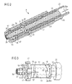
- Figure 2 schematically shows a perspective sectional view of a part of the drug delivery device of Figure 1 .
- Figure 2 illustrates the drive mechanism of the drug delivery device 1, which mechanism was mentioned before.
- the drive mechanism comprises a drive member 14.
- the drive mechanism comprises a rotation member 15.
- the drive mechanism comprises a stop member 16.
- the drive mechanism comprises a dose member 22.
- Figure 3 schematically shows a sectional side view of the part of the drug delivery device shown in Figure 2 .
- the drive mechanism is arranged within the housing 11 of the drug delivery device 1.
- the rotation member 15 is rotatable in a dose setting direction with respect to the housing 11 for setting a dose of the drug 5.
- the rotation member 15 is rotatable in a dose delivery direction with respect to the housing 11, as indicated by arrow 26b, for delivering the set dose of the drug 5.
- the dose delivery direction may be opposite to the dose setting direction.
- the rotation member 15 may comprise an outer thread (see thread 24, Figure 6 ).
- the rotation member 15 comprises at least one stop feature (see stop feature 36 in Figures 4 to 7 ).
- the stop feature 36 may be provided within the rotation member 15.
- the rotation member 15 and the stop feature 36 are unitary.
- the stop feature 36 may be arranged at a distal end section of the rotation member 15.
- the stop feature 36 may protrude radially inwardly from the rotation member 15.
- the stop feature may be configured to prevent setting of a dose of the drug 5 which may exceed a present quantity of the drug 5 held in the cartridge 4. Operation of the stop feature 36 will be described in connection with Figures 4 to 7 .
- the drive member 14 is rotatable with respect to the housing 11.
- the drive member 14 and the rotation member 15 are preferably configured to rotate about a common rotation axis when delivering the set dose.
- the rotation axis may be a main longitudinal axis of the housing 11.
- the rotation axis runs along the piston rod 10 and, in particular, along a main direction of extent of the piston rod 10.
- the rotation member 15 is coupled to the drive member 14 by a uni-directional clutch mechanism, in particular a friction clutch mechanism, for example a slipping clutch.
- the clutch mechanism permits rotational movement of the rotation member 15 with respect to the drive member 14 when the rotation member 15 rotates in the dose setting direction with respect to the housing 11, e.g. when setting a dose of the drug.
- the clutch mechanism prevents rotational movement of the rotation member 15 with respect to the drive member 14, when the rotation member 15 rotates in the dose delivery direction with respect to the housing 11, e.g. when delivering the set dose of the drug 5. Consequently, the drive member 14 follows rotational movement of the rotation member 15 in the dose delivery direction with respect to the housing 11 when delivering the set dose of the drug 5.
- the drive member 14 may be arranged to abut or engage the rotation member 15.
- the drive member 14 comprises a toothing (see toothing 28 in Figure 3 ), which may be arranged at the proximal end section of the drive member 14, for example.
- the rotation member 15 comprises a toothing (see toothing 29 in Figure 3 ), which may be arranged at the distal end section of the rotation member 15, for example.
- toothing 29 may be arranged at one end section of the rotation member 15 which faces the drive member 14.
- Toothing 29 and toothing 28 may be configured to mate with each other.
- Toothing 28 comprises a plurality of teeth (teeth 30 in Figure 3 ).
- Toothing 29 comprises a plurality of teeth (see teeth 31 in Figure 3 ). Teeth 30 and teeth 31 may extend along the rotation axis.
- the rotation axis may be oriented along the main longitudinal axis of the housing 11.
- a respective tooth of teeth 30 and teeth 31 may be ramp-shaped, in particular along an azimuthal direction with respect to the rotation axis.
- the ramp of the respective tooth 30, 31 is limited in the azimuthal direction by a steep end face of said tooth, e.g. a face of the tooth 30, 31 that runs parallel to the rotation axis.
- the drive member 14 may engage the piston rod 10.
- the drive member 14 may be splined to the piston rod 10.
- the piston rod 10 comprises a guide notch (see guide notch 27, Figures 5 and 7 ).
- the drive member 14 may comprise a corresponding guide rib (not explicitly shown) for engaging the guide notch.
- the guide rib extends inside the drive member 14 along the main longitudinal axis of the housing 11.
- the corresponding guide notch 27 may extend at an outer side of the piston rod 10 along the main longitudinal axis of the piston rod 10.
- the splined connection of the drive member 14 and the piston rod 10 prevents relative rotational movement of the drive member 14 with respect to piston rod 10 and vice versa. Hence, the drive member 14 and the piston rod 10 are permanently rotationally locked.
- the drive member 14 is configured to transfer force, preferably torque, to the piston rod 10.
- the force transferred may cause the piston rod 10 to be rotated with respect to the housing 11. Additionally or alternatively, the force transferred may cause the piston rod 10 to be displaced in the distal direction with respect to the housing 11 for delivering a dose of the drug 5.
- the piston rod 10 comprises a thread (see thread 35, Figure 4 , 5 and 7 ).
- the thread 35 may be arranged at an outer surface of the piston rod 10.
- a counterpart, e.g. a further thread, may be provided inside the housing 11 for a threaded engagement of the housing 11 and piston rod 10. Rotational movement of the piston rod 10 may be converted into axial movement of the piston rod 10 in the distal direction with respect to the housing 11 due to the threaded engagement of the piston rod 10 and the housing 11.
- the drive member 14 may be arranged between the stop member 16 and the rotation member 15.
- the stop member 16 is configured to prevent rotational movement of the drive member 14 in the dose setting direction with respect to the housing 11 when setting the dose of the drug 5. Consequently, when setting the dose, the rotation member 15 rotates with respect to the drive member 14 and with respect to the stop member 16.
- the stop member 16 is preferably secured against rotation with respect to the housing 11.
- the stop member 16 may be splined to the housing 11.
- the stop member 16 may be coupled to the drive member 14 by means of a uni-directional clutch mechanism.
- the clutch mechanism prevents rotational movement of the drive member 14 with respect to the stop member 16 when the rotation member 15 rotates in the dose setting direction with respect to the housing, e.g. when setting the dose of the drug 5.
- the clutch mechanism permits rotational movement of the drive member 14 with respect to the stop member 16 when the rotation member 15 rotates in the dose delivery direction with respect to the housing 11, e.g. when delivering the set dose of the drug 5.
- the stop member 16 may be arranged to abut or engage the drive member 14, preferably when setting and when delivering the set dose.
- the stop member 16 comprises a toothing (see toothing 32 in Figure 3 ) at one end section which faces the drive member 14, for example the proximal end section of the stop member 16.
- the teeth of toothing 32 may be ramp-shaped and may be disposed along a perimeter of the drive member 14.
- the drive member 14 comprises a toothing (see toothing 33 in Figure 3 ), preferably at the distal end section of the drive member 14. Thereby, toothing 28 and toothing 33 of the drive member 14 are disposed oppositely. Toothing 33 may be configured in accordance with toothing 29 of the rotation member 15. Toothing 32 and toothing 33 may be configured to cooperate for preventing rotation of the drive member 14 with respect to the housing 11 and with respect to the stop member 16 when setting the dose of the drug 5.
- stop member 16 may be secured against rotational movement with respect to the housing 11.
- stop member 16 may be axially displaceable with respect to the housing 11, as indicated by arrow 26c in Figure 3 .
- the stop member 16 may comprise a plurality of guiding members, for example guide lugs 17.
- Guide lugs 17 may engage with corresponding guide slots 18.
- the guide slots 18 may be provided in the housing 11.
- a guide lug 17 cooperates with a guide slot 18 to prevent rotational movement of the stop member 16 with respect to the housing 11 with distal movement of the stop member 16 with respect to the housing 11 being allowed.
- the drive mechanism further comprises a resilient member 19, for example a spring member.
- the resilient member 19 may be biased during dose delivery.
- the resilient member 19 may provide a force keeping the drive member 14 in permanent mechanical cooperation, e.g. engagement, with the stop member 16 and the rotation member 15, when setting and delivering a dose.
- the drive mechanism comprises a support member 20.
- the support member 20 may be secured against axial and rotational movement with respect to the housing 11.
- the support member 20 may be unitary with the housing 11.
- the support member 20 may be a protrusion, for example.
- the rotation member 15 may extend through an opening in support member 20.
- Support member 20 may provide a counter force to the force exerted by the resilient member 19.
- the rotation member 15 comprises a protruding portion 21.
- the protruding portion 21, e.g. a flange portion, may protrude radially outwardly with respect to the rotation member 15.
- the protruding portion 21 may be configured to abut support member 20. The protruding portion 21 prevents proximal displacement of the rotation member 15 with respect to the housing 15.
- the dose member 22 may be a part of the dose part 12 (see Figure 1 ) or operatively connected to the dose part 12.
- the rotation member 15 may be arranged inside the dose member 22.
- Dose member 22 may be movable with respect to the housing 11. Dose member 22 may be moved in the proximal direction with respect to the rotation member 15 and with respect to the housing 11 when setting a dose, which is indicated by arrow 26a in Figure 2 . Dose member 22 may be moved in the distal direction with respect to the rotation member 15 and with respect to the housing 11 for delivering the set dose.
- the dose member 22 may engage the housing 11.
- the dose member 22 is secured against rotation with respect to the housing 11.
- the dose member 22 may comprise a guide feature 23, for example a guide slot, engaging with another guide feature (not explicitly shown in Figure 2 and Figure 3 ), for example a guide lug, which may be provided in the housing 11.
- the dose member 22 may be coupled to, preferably threadedly engaged with, the rotation member 15.
- the rotation member 15 may comprise the outer thread 24.
- the dose member may comprise a thread 25. Thread 25 may be provided inside the dose member 22. Thread 24 may be engaged with thread 25.
- the dose member 22 and the rotation member 15 may be threadedly engaged such that axial movement of the dose member 22 may be converted into rotational movement of the rotation member 15.
- movement of the dose member 22 in proximal direction with respect to the housing 11 when setting a dose may be converted into rotation of the rotation member 15 in the dose setting direction with respect to the housing 11.
- Movement of the dose member 22 in the distal direction with respect to the housing 11 when delivering the set dose may be converted into rotation of the rotation member 15 in the dose delivery direction with respect to the housing 11.
- the drive member 14, the rotation member 15, the stop member 16 and the dose member 22 may comprise or may be embodied as a sleeve, respectively.
- the piston rod 10 may be arranged and/or driven through at least one, or more or all of said sleeves.
- Figure 4A through 4C show the drug delivery device of Figure 1 or parts thereof.
- Figure 4A shows an inner view of the drug delivery device 1.
- Figure 4B shows an exploded view of the drug delivery device 1.
- Figure 4C shows an inner view of the housing 11.
- the rotation member 15 comprises the stop feature 36 as mentioned previously.
- the rotation member may comprise two or more stop features 36.
- the stop feature 36 is localized at the distal end section of the rotation member 15.
- the stop feature 36 is provided inside the rotation member 15.
- the stop feature 36 is preferably arranged at a distal end section of the rotation member 15.
- the stop feature 36 is arranged inside the rotation member 15.
- the stop feature 36 protrudes radially inwardly from the rotation member 15.
- the stop feature 36 is preferably integrally formed with the rotation member 15.
- a separate stop feature 36 may be connected to the rotation member 15.
- the stop feature 36 is secured against translational and rotational movement with respect to the rotation member 15.
- the piston rod 10 comprises two blocking members 34.
- the blocking members 34 may be arranged in a proximal end section of the piston rod 10.
- the blocking members 34 may be oppositely arranged.
- the piston rod 10 may comprise only one blocking member 34.
- the piston rod may 10 comprise three or more blocking members 34.
- the blocking members 34 are integrally formed with the piston rod 10.
- the blocking members 34 may be connected to the piston rod 10.
- the blocking members 34 may protrude radially outwardly from the piston rod 10.
- the blocking members 34 are secured against translational and rotational movement with respect to the piston rod 10.
- the stop feature 36 rotates together with the rotation member 15 in the dose setting direction with respect to the blocking members 34 and with respect to the housing 11 for setting a dose.
- the stop feature 36 may be rotated about a stop feature angle in the dose setting direction.
- the stop feature 36 is rotated by less than 360 degrees in the dose setting direction with respect to the blocking members 34.
- the blocking members 34 may be secured against rotation in the dose setting direction with respect to the housing 11 as the piston rod 10 is prevented from being rotated in the dose setting direction with respect to the housing 11, as it was described previously.
- the stop feature 36 may be rotated about a stop feature angle of 90 degrees, for example, for setting a dose of the drug 5. As being part of the rotation member 15 significant axial displacement of the stop feature 36, or any axial displacement, with respect to the housing 11 may be prevented, when setting and delivering a dose.
- the stop feature 36 rotates together with the rotation member 15 in the dose delivery direction for delivering the set dose of the drug 5. Accordingly, the blocking members 34 rotate together with the piston rod 10 in the dose delivery direction for delivering the set dose of the drug 5.
- the stop feature 36 is configured to be rotated together with the blocking members 34 in the dose delivery direction with respect to the housing 11. The blocking members 34 may rotate with respect to the stop feature 36.
- the blocking members 34 are configured to be displaced together with the piston rod 10 in the distal direction with respect to the housing 11 for delivering the set dose of the drug 5, thereby being axially displaced with respect to the stop feature 36.
- the blocking members 34 may be axially displaced from an axial starting position and towards an axial interaction position. In the axial starting position the blocking members 34 may be axially offset from the stop feature 36. In the axial interaction position the blocking members 34 may overlap with the stop feature 36.
- the stop feature 36 may pass an angular position of the blocking members 34 while being rotated about the stop feature angle.
- the stop feature 36 may be rotatable about at least a minimum stop feature angle, e.g. the angle required for completion of a dose setting action, e.g. 90 degrees, in the dose setting direction with respect to the housing 11 for setting a dose.
- the blocking members 34 may be rotated about a blocking member delivery angle in the dose delivery direction with respect to the housing 11 when being displaced from the axial starting position towards the axial interaction position.
- the blocking members 34 are rotated by 360 degrees or more in the dose delivery direction with respect to the housing 11 when being displaced from the axial starting position towards the axial interaction position.
- the blocking members 34 when a last dose has been delivered, e.g. when a subsequent minimum settable dose of the drug 5 would exceed the quantity of the drug 5 still present in the cartridge 4, the blocking members 34 have been axially displaced with respect to the stop feature 36 such that the blocking members 34 are positioned in the axial interaction position, e.g. the blocking members 34 overlap the stop feature 36.
- the total axial displacement distance of the blocking members 34 from the axial starting position into the axial interaction position corresponds to the total amount of the drug 5 held in the cartridge 4.
- the axial interaction position may be defined by the axial position of the stop feature 36 with respect to the housing 11. Hence, when the blocking members 34 have reached the axial position of the stop feature 36 the blocking members 34 are in the axial interaction position.
- the drive mechanism may be configured such that axial displacement of the piston rod 10 for delivering the set dose results in the blocking members 34 being in the axial interaction position when the distal end position of the piston rod 10 was reached.
- the outer thread 35 of the piston rod 10 and the inner thread of the housing 11 may be adapted such that the blocking members 34 overlap with the stop feature 36 when the piston rod 10 has reached the distal end position, e.g. when the piston 9 has reached the most distal position in the cartridge 4.
- the angular distance between the blocking members 34 and the stop feature 36 is expediently less than the stop feature angle.
- the minimum rotation angle of the stop feature 36 necessary for setting a minimum dose may be greater than the angular distance between the stop feature 36 and the blocking members 34. Hence, a further dose setting action is prevented when the blocking members 34 are in the axial interaction position.
- the stop feature 36 and the blocking members 34 provide an end-stop mechanism for the drug delivery device 1. Setting of a dose of the drug 5 which exceeds a quantity of the drug 5 still held in the cartridge 4 is thus effectively prevented. In this way, underdosing, which may have fatal or even lethal consequences for the user, may be prevented.
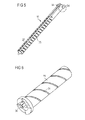
- Figure 5 schematically shows a perspective sectional view of a part of Figure 4B .
- Figure 5 shows the piston rod 10 comprising the two blocking members 34.
- the blocking members 34 are disposed oppositely and protrude radially outwardly from the piston rod 10 as described above.
- the piston rod 10 may comprise guide notch 27.
- Guide notch 27 may enable splined connection of the piston rod 10 with the drive member 14 as described in connection with the description of Figures 2 and 3 .
- the piston rod 10 comprises two guide notches 27.
- the guide notches 27 may be arranged oppositely (see Figure 7 ).
- the piston rod 10 comprises the outer thread 35. Outer thread 35 may enable threaded connection of the piston rod 10 with the housing 11, as explained in conjunction with the description of Figure 1 .
- Figure 6 schematically shows a perspective sectional view of another part of Figure 4B .
- Figure 6 shows the rotation member 15.
- the rotation member 15 comprises the stop feature 36.
- the stop feature 36 protrudes radially inwardly from the rotation member 15.
- the rotation member 15 comprises thread 24. Thread 24 may enable threaded engagement of the rotation member 15 and the dose member 22 as mentioned previously.
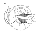
- Figure 7 schematically shows a sectional view of a part of the drug delivery device of Figure 1 .
- Figure 7 shows mechanical cooperation of the stop feature 36 and the stop members 34.
- a last dose of the drug 5 held in the cartridge 4 may have been dispensed, i.e. the piston 9 may have reached the most distal end position in the cartridge 4, and thus, the blocking members 34 are positioned in the axial interaction position.
- the blocking members 34 and the stop feature 36 mechanically cooperate, in particular overlap, in the interaction position. Rotation of the stop feature 36 and hence, of the rotation member 15 may be prevented in this way as described in connection with Figure 4 . Thus, setting of a subsequent dose of the drug 5 may be prevented.
- the device 1 effectively prevents setting of a dose of the drug 5 which exceeds the present quantity of the drug 5 held in the cartridge 4. Hence, the device 1 provides an end-stop mechanism. In this way, underdosing, which may have fatal or lethal consequences for the user, may be prevented. Consequently, the drug delivery device 1 described herein provides an increased safety for the user.
- the device 1 is a fixed dose drug delivery device, e.g. a device configured to dispense a plurality of pre-set doses of the drug 5, in particular doses which may not be varied by the user.
- the angle by which the stop feature 36 is rotated in the dose setting direction for setting a dose of the drug i.e. the stop feature angle, may be the same for each dose setting action.
Landscapes
- Health & Medical Sciences (AREA)
- Vascular Medicine (AREA)
- Engineering & Computer Science (AREA)
- Anesthesiology (AREA)
- Biomedical Technology (AREA)
- Heart & Thoracic Surgery (AREA)
- Hematology (AREA)
- Life Sciences & Earth Sciences (AREA)
- Animal Behavior & Ethology (AREA)
- General Health & Medical Sciences (AREA)
- Public Health (AREA)
- Veterinary Medicine (AREA)
- Infusion, Injection, And Reservoir Apparatuses (AREA)
Abstract
An assembly for a drug delivery device (1) comprises a housing (11), at least one stop feature (36) and at least one blocking member (34). For setting a dose of a drug (5), the stop feature (36) is configured to be rotated in a dose setting direction with respect to the blocking member (34) and with respect to the housing (11). For delivering the set dose of the drug (5), the blocking member (34) is configured to be axially displaced with respect to the stop feature (36) away from an axial starting position and towards an axial interaction position. When the blocking member (34) is in the axial starting position, the blocking member (34) is axially offset from the stop feature (36) and, when the blocking member (34) is in the axial interaction position, the blocking member (34) is configured to mechanically cooperate with the stop feature (36) such that rotation of the stop feature (36) in the dose setting direction with respect to the housing (11) is prevented.
Description
- This disclosure relates to an assembly for a drug delivery device and a drug delivery device incorporating such an assembly.
- In a drug delivery device a piston within a cartridge that contains a drug may be provided. The piston may be displaced with respect to the cartridge for delivering a dose of the drug from the cartridge. It is desirable that the dispensed dose of the drug matches the dose which was previously set by a user as good as possible. That is to say, the device should have a high dose accuracy. In particular, it should be avoided that a dose dispensing action may be triggered when the size of the set dose exceeds the quantity of drug present in the cartridge.
- Drug delivery devices are described in documents
WO 2008/031238 A1 andUS 2007/0197976 A1 . - It is an object of the present disclosure to provide an assembly facilitating provision of an improved drug delivery device, for example a device with high dose accuracy.
- This object may be achieved by the subject matter of the independent claim. Further features and advantageous embodiments are the subject matter of the dependent claims.
- According to one aspect an assembly for a drug delivery device is provided. The assembly may comprise a housing. The assembly may comprise at least one stop feature. The assembly may comprise at least one blocking member. For setting a dose of a drug the stop feature may be configured to be rotated in a dose setting direction with respect to the blocking member and with respect to the housing. For delivering the set dose of the drug the blocking member may be configured to be axially displaced with respect to the stop feature away from an axial starting position and towards an axial interaction position. When the blocking member is in the axial starting position, the blocking member may be axially offset from the stop feature. When the blocking member is in the axial interaction position the blocking member may be arranged and/or configured to mechanically cooperate with, in particular to abut, the stop feature. By this mechanical cooperation rotation of the stop feature in the dose setting direction with respect to the housing may be prevented.
- A further aspect relates to a drug delivery device. The drug delivery device expediently comprises the assembly described above. The drug delivery device comprises a cartridge. The cartridge may hold a plurality of doses of the drug. The assembly may provide an end-stop mechanism for the drug delivery device. The end-stop mechanism may be configured to prevent setting of a dose of the drug which exceeds a quantity of the drug present in the cartridge.
- The drug delivery device may be an injection device. The drug delivery device may be a pen-type device, e.g. a pen-type injector. Preferably, the drug delivery device is a device configured to dispense pre-set doses of the drug. The drug may be a liquid medication, such as long-acting or short-acting insulin, heparin or growth hormones.
- For setting a dose of the drug the stop feature may be rotated in the dose setting direction with respect to the housing. For delivering the set dose the stop feature may be rotated in a dose delivery direction with respect to the housing. The dose delivery direction may be opposite to the dose setting direction.
- In the axial interaction position the blocking member may be positioned at the axial position of the stop feature with respect to the housing such that the blocking member and the stop feature may interact, in particular abut. When the blocking member is in the axial interaction position the whole amount of the drug held in the cartridge which was intended for dispense may have been dispensed. Consequently, dispensing of a subsequent full-size dose of the drug may no longer be possible. In the axial interaction position setting of a subsequent dose of the drug may be prevented due to mechanical cooperation of the stop feature and the blocking member, and hence, underdosing may be prevented. In this way, a user-friendly and safe drug delivery device may be achieved.
- According to an embodiment, for delivering the set dose of the drug the blocking member and the stop feature are configured to rotate together in a dose delivery direction with respect to the housing.
- According to an embodiment, the blocking member is secured against rotation in the dose setting direction with respect to the housing. Hence, common rotation of the blocking member and the stop feature in the dose setting direction with respect to the housing for setting a dose of the drug may be prevented when the blocking member and the stop feature mechanically cooperate with each other.
- In this way, setting of a subsequent dose of the drug, which may exceed the present quantity of the drug held in the cartridge, may be effectively prevented when the blocking member is in the interaction position.
- According to an embodiment, the stop feature is rotated about a stop feature angle in the dose setting direction with respect to the housing for setting the dose of the drug. The blocking member may be rotated about a blocking member delivery angle in the dose delivery direction with respect to the housing when the blocking member is displaced from the axial starting position towards the axial interaction position. When the blocking member is in the axial interaction position the angular distance between the blocking member and the stop feature is expediently less than the stop feature angle.
- In particular, the minimum rotation angle of the stop feature necessary for setting a minimum dose may be greater than the angular distance between the stop feature and the blocking member in the interaction position. Hence, completion of a further dose setting action is prevented when the blocking member is in the axial interaction position.
- Preferably, the stop feature is rotated by less than 360 degrees in the dose setting direction with respect to the housing for setting the dose of the drug.
- Preferably, the blocking member is rotated by 360 degrees or more in the dose delivery direction with respect to the housing when being displaced from the axial starting position towards the axial interaction position.
- According to an embodiment, when the blocking member is out of the axial interaction position, the stop feature may pass the angular position of the blocking member when being rotated in the dose setting direction.
- Hence, when the amount of the drug held in the cartridge exceeds the size of a dose to be set and delivered the stop feature may be rotatable in the dose setting direction with respect to the housing, thereby passing the angular position of the blocking member without mechanical cooperation, in particular abutment, with the blocking member. Thus, setting of at least a minimum dose of the drug is enabled when the blocking member is not in the axial interaction position.
- According to an embodiment, the axial interaction position may be defined by the axial position of the stop feature within the housing.
- Preferably, when a last dose has been delivered, e.g. when a subsequent minimum settable dose of the drug would exceed the present quantity of the drug in the cartridge, the blocking member has been axially displaced with respect to the stop feature such that the blocking member is positioned at the axial position of the stop feature, i.e. the blocking member overlaps the stop feature. Preferably, axial displacement distance of the blocking member from the axial starting position to the axial interaction position corresponds to the total amount of the drug held in the cartridge.
- According to an embodiment, a rotation member is provided. The rotation member may be configured to rotate in the dose setting direction with respect to the housing for setting the dose of the drug. The rotation member may be configured to rotate in the dose delivery direction with respect to the housing for delivering the set dose of the drug. The stop feature may be part of the rotation member. The stop feature may thus rotate when the rotation member rotates.
- According to an embodiment, a piston rod is provided. The blocking member may be part of the piston rod. The piston rod may be configured to be axially displaced with respect to the housing for delivering a dose of the drug.
- Preferably, the rotation axis runs along the piston rod and, in particular, along a main direction of extent of the piston rod. Preferably, the piston rod is threadedly engaged with the housing. The piston rod may be configured to displace the piston axially with respect to the cartridge for expelling the set dose of the drug from the cartridge.
- According to an embodiment, the stop feature protrudes radially, preferably radially inwardly, from the rotation member.
- According to an embodiment, the blocking member protrudes radially, preferably radially outwardly, from the piston rod.
- According to an embodiment, a drive member is provided. The drive member may be adapted to follow rotational movement of the rotation member in the dose delivery direction with respect to the housing by mechanical cooperation with the rotation member. Rotation of the drive member in the dose delivery direction with respect to the housing may be converted into axial movement of the piston rod with respect to the housing. A stop member may be provided. The stop member may be adapted to prevent rotational movement of the drive member in the dose setting direction with respect to the housing by mechanical cooperation with the drive member, when the rotation member is rotated in the dose setting direction with respect to the housing.
- The drive member and the stop member may be coupled, preferably permanently for setting and delivering a dose of the drug, to one another by a uni-directional friction clutch mechanism, for example a slip clutch. The clutch mechanism may be configured to prevent relative rotational movement between the drive member and the stop member during rotation of the rotation member in the dose setting direction. The clutch mechanism may be configured to permit relative rotational movement between the stop member and the drive member during rotation of the rotation member in the dose delivery direction. A resilient member may be provided. The resilient member may provide a force keeping the drive member in engagement, preferably permanent engagement, with the stop member and the rotation member during dose setting and dose delivery.
- The drive member and the rotation member may be coupled, preferably permanently coupled, to one another by a uni-directional friction clutch mechanism. The friction clutch mechanism may be configured to permit relative rotational movement between the rotation member and the drive member when setting a dose of the drug. In this way, rotation of the piston rod and, hence, of the blocking member in the dose setting direction may be effectively prevented. The friction clutch mechanism may be configured to prevent relative rotational movement of the rotation member and the drive member for delivering the set dose of the drug.
- According to an embodiment, the drive member and the piston rod are rotationally locked with each other. Preferably, the piston rod is splined to the drive member.
- According to an embodiment, the assembly comprises at least two blocking members. The two blocking members may be oppositely disposed.
- According to a preferred embodiment, an assembly for a drug delivery device is provided. The assembly comprises a housing, at least one stop feature and at least one blocking member. For setting a dose of a drug, the stop feature is configured to be rotated in a dose setting direction with respect to the blocking member and with respect to the housing and, for delivering the set dose of the drug, the blocking member is configured to be axially displaced with respect to the stop feature away from an axial starting position and towards an axial interaction position. When the blocking member is in the axial starting position, the blocking member is axially offset from the stop feature and, when the blocking member is in the axial interaction position, the blocking member is configured to mechanically cooperate with the stop feature such that rotation of the stop feature in the dose setting direction with respect to the housing is prevented.
- Of course, features described above in connection with different aspects and embodiments may be combined with each other and with features described below.
- Further features and refinements become apparent from the following description of the exemplary embodiments in connection with the accompanying figures.
-
Figure 1 schematically shows a partly sectional side view of an exemplary embodiment of a drug delivery device, -
Figure 2 schematically shows a perspective sectional view of a part of the drug delivery device ofFigure 1 . -
Figure 3 schematically shows a sectional side view of the part of the drug delivery device shown inFigure 2 , -
Figure 4A throughFigure 4C show the drug delivery device ofFigure 1 or parts thereof, -
Figure 5 schematically shows a perspective sectional view of a part ofFigure 4B , -
Figure 6 schematically shows a perspective sectional view of another part ofFigure 4B , -
Figure 7 schematically shows a perspective sectional view of a part of the drug delivery device ofFigure 1 . - Like elements, elements of the same kind and identically acting elements may be provided with the same reference numerals in the figures.
- In
Figure 1 a drug delivery device 1 is shown. The drug delivery device 1 comprises acartridge unit 2. The drug delivery device 1 comprises adrive unit 3. The drug delivery device has ahousing 11. - The
cartridge unit 2 comprises acartridge holder 39. Thecartridge unit 2 comprises acartridge 4. Thecartridge 4 is, preferably releasably, secured to thecartridge holder 39. Thecartridge holder 39 stabilizes thecartridge 4 mechanically. - The
cartridge 4 may hold a plurality of doses of a drug 5. The drug 5 is preferably a liquid medication, comprising, for example, insulin, like short-acting or long acting-insulin, heparin or growth hormones. Thecartridge 4 has an outlet 6. The drug 5 can be dispensed from thecartridge 4 through the outlet 6. The outlet 6 may be covered by a membrane. The membrane may protect the drug 5 against external influences during storage of thecartridge 4. The drug delivery device 1 comprises a piston 9. The piston 9 may be retained in thecartridge 4. - The
drive unit 3 comprises apiston rod 10. Thedrive unit 3 comprises adose part 12. Thedose part 12 comprises a dose knob 13. - The drug delivery device 1 and the
housing 11 have a distal end and a proximal end. The term "distal end" 7 designates that end of the drug delivery device 1 or a component thereof which is or is to be arranged closest to a dispensing end of the drug delivery device 1. The term "proximal end" 8 designates that end of the device 1 or a component thereof which is or is to be arranged furthest away from the dispensing end of the device 1. - The drug delivery device 1 may be a pen-type device, in particular a pen-type injector. The device 1 may be a disposable or a re-usable device. The device 1 may be configured to dispense fixed doses of the drug 5 or variable, preferably user-settable doses of the drug 5.
- The drug delivery device 1 may comprise a needle assembly (not explicitly shown), comprising for example a needle covered by a needle mount, a needle retainer and/or a needle seal. The needle assembly may be releasably attached to the distal end of the
cartridge holder 39. The membrane may be pierced by the needle for dispensing a dose of the drug 5. Alternatively, the drug delivery device 1 may be a needle-free device. - The
housing 11 may be designed to enable a safe and comfortable handling of the drug delivery device 1. Thehousing 11 may be configured to house, fix, protect or guide inner components of the drug delivery device 1,e.g. piston rod 10,dose part 12. Preferably, thehousing 11 limits or prevents the exposure of the inner components to contaminants such as liquid, dirt or dust. Thehousing 11 may be a unitary or a multipart component. Thehousing 11 may comprise a tubular or cylindrical shape, as shown inFigure 1 . Alternatively, thehousing 11 may comprise a non-tubular shape. - The piston 9 is retained within the
cartridge 4. The piston 9 is movable with respect to thecartridge 4. The piston 9 may seal thecartridge 4 proximally. Movement of the piston 9 in the distal direction with respect to thecartridge 4 causes the drug 5 to be dispensed from thecartridge 4 through the outlet 6. - The
piston rod 10 may operate through thehousing 11 of the drug delivery device 1. Thepiston rod 10 may be designed to transfer axial movement through the drug delivery device 1, for example for the purpose of dispensing the drug 5 (see alsoFigures 2 and 3 for more details). In particular, thepiston rod 10 may be designed to transfer force to the piston 9, thereby pushing the piston 9 in a distal direction with respect to the housing. In this way, a dose of the drug 5 may be dispensed from thecartridge 4. The size of the dispensed dose is determined by the distance by which the piston 9 is displaced in the distal direction with respect to thehousing 11. - A bearing
member 38 may be arranged between the piston 9 and thepiston rod 10 to advance the piston 9. The bearingmember 38 may be displaced together with thepiston rod 10 with respect to thehousing 11. Thepiston rod 10 may be rotatable with respect to the bearingmember 38. - The
piston rod 10 may be made of a flexible or a rigid material. Thepiston rod 10 may have a circular or a non-circular cross-section. Thepiston rod 10 may be a simple rod, a lead-screw, a rack, a pinion system or the like. Thepiston rod 10 may be of unitary or multipart construction. - The
cartridge unit 2 and thedrive unit 3 may be, preferably releasably, secured to one another. For this purpose, a proximal end of thecartridge unit 2 may be secured to a distal end of thedrive unit 3, for example by a threaded connection. If thecartridge unit 2 is releasably secured to thedrive unit 3, the device 1 may be a re-usable device. In this case, thecartridge unit 2 may be detached from thedrive unit 3 for providing for anew cartridge 4, if all of the doses of the drug 5 have already been dispensed, and re-attached to thedrive unit 3 thereafter. If thecartridge unit 2 is irreleasably secured to thedrive unit 3 the drug delivery device 1 may be a disposable device. - The
drive unit 3 comprises a drive mechanism, which is described in detail in connection with the description ofFigures 2 and 3 .Dose part 12 may be part of the drive mechanism. Thedose part 12 may be movable with respect to thehousing 11. Thedose part 12 may be movable in a proximal direction for setting a dose of the drug 5. Thedose part 12 may be movable in the distal direction with respect to thehousing 11 for delivering the set dose of the drug 5. - The distance by which the
dose part 12 is moved proximally with respect to thehousing 11 for setting the dose of the drug 5 may determine a size of the dose of the drug 5. A proximal end position and a distal end position of thedose part 12 with respect to thehousing 11 may be determined by a respective stop feature (not explicitly shown) limiting the proximal or distal movement of thedose part 12 with respect to thehousing 11. Thedose part 12 may comprise the dose knob 13. The dose knob 13 may be configured to be gripped by a user. The dose knob 13 may be secured against movement with respect to thedose part 12. - The drug delivery device 1 may be a manually, in particular a non-electrically, driven device. A, preferably user-applied, force causing the
dose part 12 to be moved distally with respect to thehousing 11 may be transferred to thepiston rod 10 by the drive mechanism, which is described later on in more detail. Preferably, the drive mechanism may be configured to leave thepiston rod 10 stationary with respect to thehousing 11 when thedose part 12 is moved in the proximal direction with respect to thehousing 11. -
Figure 2 schematically shows a perspective sectional view of a part of the drug delivery device ofFigure 1 . In particular,Figure 2 illustrates the drive mechanism of the drug delivery device 1, which mechanism was mentioned before. - The drive mechanism comprises a
drive member 14. The drive mechanism comprises arotation member 15. The drive mechanism comprises astop member 16. The drive mechanism comprises adose member 22. -
Figure 3 schematically shows a sectional side view of the part of the drug delivery device shown inFigure 2 . - The drive mechanism is arranged within the
housing 11 of the drug delivery device 1. Therotation member 15 is rotatable in a dose setting direction with respect to thehousing 11 for setting a dose of the drug 5. Therotation member 15 is rotatable in a dose delivery direction with respect to thehousing 11, as indicated byarrow 26b, for delivering the set dose of the drug 5. The dose delivery direction may be opposite to the dose setting direction. Therotation member 15 may comprise an outer thread (seethread 24,Figure 6 ). - The
rotation member 15 comprises at least one stop feature (seestop feature 36 inFigures 4 to 7 ). Thestop feature 36 may be provided within therotation member 15. Preferably, therotation member 15 and thestop feature 36 are unitary. Thestop feature 36 may be arranged at a distal end section of therotation member 15. Thestop feature 36 may protrude radially inwardly from therotation member 15. The stop feature may be configured to prevent setting of a dose of the drug 5 which may exceed a present quantity of the drug 5 held in thecartridge 4. Operation of thestop feature 36 will be described in connection withFigures 4 to 7 . - The
drive member 14 is rotatable with respect to thehousing 11. Thedrive member 14 and therotation member 15 are preferably configured to rotate about a common rotation axis when delivering the set dose. The rotation axis may be a main longitudinal axis of thehousing 11. Preferably, the rotation axis runs along thepiston rod 10 and, in particular, along a main direction of extent of thepiston rod 10. - The
rotation member 15 is coupled to thedrive member 14 by a uni-directional clutch mechanism, in particular a friction clutch mechanism, for example a slipping clutch. The clutch mechanism permits rotational movement of therotation member 15 with respect to thedrive member 14 when therotation member 15 rotates in the dose setting direction with respect to thehousing 11, e.g. when setting a dose of the drug. The clutch mechanism prevents rotational movement of therotation member 15 with respect to thedrive member 14, when therotation member 15 rotates in the dose delivery direction with respect to thehousing 11, e.g. when delivering the set dose of the drug 5. Consequently, thedrive member 14 follows rotational movement of therotation member 15 in the dose delivery direction with respect to thehousing 11 when delivering the set dose of the drug 5. - The
drive member 14 may be arranged to abut or engage therotation member 15. For engaging therotation member 15, thedrive member 14 comprises a toothing (seetoothing 28 inFigure 3 ), which may be arranged at the proximal end section of thedrive member 14, for example. In addition, therotation member 15 comprises a toothing (see toothing 29 inFigure 3 ), which may be arranged at the distal end section of therotation member 15, for example. In particular, toothing 29 may be arranged at one end section of therotation member 15 which faces thedrive member 14. Toothing 29 andtoothing 28 may be configured to mate with each other.Toothing 28 comprises a plurality of teeth (teeth 30 inFigure 3 ). Toothing 29 comprises a plurality of teeth (seeteeth 31 inFigure 3 ).Teeth 30 andteeth 31 may extend along the rotation axis. The rotation axis may be oriented along the main longitudinal axis of thehousing 11. - A respective tooth of
teeth 30 andteeth 31 may be ramp-shaped, in particular along an azimuthal direction with respect to the rotation axis. The ramp of therespective tooth tooth teeth rotation member 15 is rotated further in the dose delivery direction with respect to thehousing 11, the steep sides stay in abutment and hence, thedrive member 14 follows rotation of therotation member 15. When therotation member 15 rotates in the dose setting direction with respect to thehousing 11, the ramps of theteeth 30 31 slide along each other and hence, therotation member 15 rotates with respect to thedrive member 14. - The
drive member 14 may engage thepiston rod 10. Thedrive member 14 may be splined to thepiston rod 10. Preferably, thepiston rod 10 comprises a guide notch (seeguide notch 27,Figures 5 and7 ). Thedrive member 14 may comprise a corresponding guide rib (not explicitly shown) for engaging the guide notch. Preferably, the guide rib extends inside thedrive member 14 along the main longitudinal axis of thehousing 11. Thecorresponding guide notch 27 may extend at an outer side of thepiston rod 10 along the main longitudinal axis of thepiston rod 10. The splined connection of thedrive member 14 and thepiston rod 10 prevents relative rotational movement of thedrive member 14 with respect topiston rod 10 and vice versa. Hence, thedrive member 14 and thepiston rod 10 are permanently rotationally locked. - The
drive member 14 is configured to transfer force, preferably torque, to thepiston rod 10. The force transferred may cause thepiston rod 10 to be rotated with respect to thehousing 11. Additionally or alternatively, the force transferred may cause thepiston rod 10 to be displaced in the distal direction with respect to thehousing 11 for delivering a dose of the drug 5. - The
piston rod 10 comprises a thread (seethread 35,Figure 4 ,5 and7 ). Thethread 35 may be arranged at an outer surface of thepiston rod 10. A counterpart, e.g. a further thread, may be provided inside thehousing 11 for a threaded engagement of thehousing 11 andpiston rod 10. Rotational movement of thepiston rod 10 may be converted into axial movement of thepiston rod 10 in the distal direction with respect to thehousing 11 due to the threaded engagement of thepiston rod 10 and thehousing 11. - The
drive member 14 may be arranged between thestop member 16 and therotation member 15. Thestop member 16 is configured to prevent rotational movement of thedrive member 14 in the dose setting direction with respect to thehousing 11 when setting the dose of the drug 5. Consequently, when setting the dose, therotation member 15 rotates with respect to thedrive member 14 and with respect to thestop member 16. Thestop member 16 is preferably secured against rotation with respect to thehousing 11. Thestop member 16 may be splined to thehousing 11. - The
stop member 16 may be coupled to thedrive member 14 by means of a uni-directional clutch mechanism. The clutch mechanism prevents rotational movement of thedrive member 14 with respect to thestop member 16 when therotation member 15 rotates in the dose setting direction with respect to the housing, e.g. when setting the dose of the drug 5. The clutch mechanism permits rotational movement of thedrive member 14 with respect to thestop member 16 when therotation member 15 rotates in the dose delivery direction with respect to thehousing 11, e.g. when delivering the set dose of the drug 5. - The
stop member 16 may be arranged to abut or engage thedrive member 14, preferably when setting and when delivering the set dose. Thestop member 16 comprises a toothing (seetoothing 32 inFigure 3 ) at one end section which faces thedrive member 14, for example the proximal end section of thestop member 16. The teeth oftoothing 32 may be ramp-shaped and may be disposed along a perimeter of thedrive member 14. - The
drive member 14 comprises a toothing (seetoothing 33 inFigure 3 ), preferably at the distal end section of thedrive member 14. Thereby,toothing 28 andtoothing 33 of thedrive member 14 are disposed oppositely.Toothing 33 may be configured in accordance with toothing 29 of therotation member 15.Toothing 32 andtoothing 33 may be configured to cooperate for preventing rotation of thedrive member 14 with respect to thehousing 11 and with respect to thestop member 16 when setting the dose of the drug 5. - As rotation of the
drive member 14 in the dose setting direction with respect to thehousing 11 is prevented, movement of thepiston rod 10 in the proximal direction with respect to thehousing 11 as well as rotation of thepiston rod 10 in the dose setting direction with respect to thehousing 11 during setting of the dose is prevented. - As mentioned previously,
stop member 16 may be secured against rotational movement with respect to thehousing 11. However, stopmember 16 may be axially displaceable with respect to thehousing 11, as indicated byarrow 26c inFigure 3 . For this purpose, thestop member 16 may comprise a plurality of guiding members, for example guide lugs 17. Guide lugs 17 may engage withcorresponding guide slots 18. Theguide slots 18 may be provided in thehousing 11. Aguide lug 17 cooperates with aguide slot 18 to prevent rotational movement of thestop member 16 with respect to thehousing 11 with distal movement of thestop member 16 with respect to thehousing 11 being allowed. - The drive mechanism further comprises a
resilient member 19, for example a spring member. Theresilient member 19 may be biased during dose delivery. Theresilient member 19 may provide a force keeping thedrive member 14 in permanent mechanical cooperation, e.g. engagement, with thestop member 16 and therotation member 15, when setting and delivering a dose. - The drive mechanism comprises a
support member 20. Thesupport member 20 may be secured against axial and rotational movement with respect to thehousing 11. Thesupport member 20 may be unitary with thehousing 11. Thesupport member 20 may be a protrusion, for example. Therotation member 15 may extend through an opening insupport member 20.Support member 20 may provide a counter force to the force exerted by theresilient member 19. - The
rotation member 15 comprises a protrudingportion 21. The protrudingportion 21, e.g. a flange portion, may protrude radially outwardly with respect to therotation member 15. The protrudingportion 21 may be configured toabut support member 20. The protrudingportion 21 prevents proximal displacement of therotation member 15 with respect to thehousing 15. - The
dose member 22 may be a part of the dose part 12 (seeFigure 1 ) or operatively connected to thedose part 12. Therotation member 15 may be arranged inside thedose member 22.Dose member 22 may be movable with respect to thehousing 11.Dose member 22 may be moved in the proximal direction with respect to therotation member 15 and with respect to thehousing 11 when setting a dose, which is indicated byarrow 26a inFigure 2 .Dose member 22 may be moved in the distal direction with respect to therotation member 15 and with respect to thehousing 11 for delivering the set dose. Thedose member 22 may engage thehousing 11. Preferably, thedose member 22 is secured against rotation with respect to thehousing 11. Thedose member 22 may comprise aguide feature 23, for example a guide slot, engaging with another guide feature (not explicitly shown inFigure 2 and Figure 3 ), for example a guide lug, which may be provided in thehousing 11. - The
dose member 22 may be coupled to, preferably threadedly engaged with, therotation member 15. For this purpose, therotation member 15 may comprise theouter thread 24. The dose member may comprise athread 25.Thread 25 may be provided inside thedose member 22.Thread 24 may be engaged withthread 25. Thedose member 22 and therotation member 15 may be threadedly engaged such that axial movement of thedose member 22 may be converted into rotational movement of therotation member 15. Thus, movement of thedose member 22 in proximal direction with respect to thehousing 11 when setting a dose may be converted into rotation of therotation member 15 in the dose setting direction with respect to thehousing 11. Movement of thedose member 22 in the distal direction with respect to thehousing 11 when delivering the set dose may be converted into rotation of therotation member 15 in the dose delivery direction with respect to thehousing 11. - The
drive member 14, therotation member 15, thestop member 16 and thedose member 22 may comprise or may be embodied as a sleeve, respectively. Thepiston rod 10 may be arranged and/or driven through at least one, or more or all of said sleeves. -
Figure 4A through 4C show the drug delivery device ofFigure 1 or parts thereof. In particular,Figure 4A shows an inner view of the drug delivery device 1.Figure 4B shows an exploded view of the drug delivery device 1.Figure 4C shows an inner view of thehousing 11. - The
rotation member 15 comprises thestop feature 36 as mentioned previously. Alternatively, the rotation member may comprise two or more stop features 36. Thestop feature 36 is localized at the distal end section of therotation member 15. Thestop feature 36 is provided inside therotation member 15. - The
stop feature 36 is preferably arranged at a distal end section of therotation member 15. Preferably, thestop feature 36 is arranged inside therotation member 15. Preferably, thestop feature 36 protrudes radially inwardly from therotation member 15. Thestop feature 36 is preferably integrally formed with therotation member 15. Alternatively, aseparate stop feature 36 may be connected to therotation member 15. Preferably, thestop feature 36 is secured against translational and rotational movement with respect to therotation member 15. - The
piston rod 10 comprises two blockingmembers 34. The blockingmembers 34 may be arranged in a proximal end section of thepiston rod 10. The blockingmembers 34 may be oppositely arranged. Alternatively, thepiston rod 10 may comprise only one blockingmember 34. Alternatively, the piston rod may 10 comprise three ormore blocking members 34. - Preferably, the blocking
members 34 are integrally formed with thepiston rod 10. Alternatively, the blockingmembers 34 may be connected to thepiston rod 10. The blockingmembers 34 may protrude radially outwardly from thepiston rod 10. - Preferably, the blocking
members 34 are secured against translational and rotational movement with respect to thepiston rod 10. - The
stop feature 36 rotates together with therotation member 15 in the dose setting direction with respect to the blockingmembers 34 and with respect to thehousing 11 for setting a dose. Thereby, thestop feature 36 may be rotated about a stop feature angle in the dose setting direction. Preferably, thestop feature 36 is rotated by less than 360 degrees in the dose setting direction with respect to the blockingmembers 34. The blockingmembers 34 may be secured against rotation in the dose setting direction with respect to thehousing 11 as thepiston rod 10 is prevented from being rotated in the dose setting direction with respect to thehousing 11, as it was described previously. - The
stop feature 36 may be rotated about a stop feature angle of 90 degrees, for example, for setting a dose of the drug 5. As being part of therotation member 15 significant axial displacement of thestop feature 36, or any axial displacement, with respect to thehousing 11 may be prevented, when setting and delivering a dose. - The
stop feature 36 rotates together with therotation member 15 in the dose delivery direction for delivering the set dose of the drug 5. Accordingly, the blockingmembers 34 rotate together with thepiston rod 10 in the dose delivery direction for delivering the set dose of the drug 5. Thus, thestop feature 36 is configured to be rotated together with the blockingmembers 34 in the dose delivery direction with respect to thehousing 11. The blockingmembers 34 may rotate with respect to thestop feature 36. - The blocking
members 34 are configured to be displaced together with thepiston rod 10 in the distal direction with respect to thehousing 11 for delivering the set dose of the drug 5, thereby being axially displaced with respect to thestop feature 36. The blockingmembers 34 may be axially displaced from an axial starting position and towards an axial interaction position. In the axial starting position the blockingmembers 34 may be axially offset from thestop feature 36. In the axial interaction position the blockingmembers 34 may overlap with thestop feature 36. - When the blocking
members 34 are out of the axial interaction position, e.g. when the blockingmembers 34 are in the axial starting position, thestop feature 36 may pass an angular position of the blockingmembers 34 while being rotated about the stop feature angle. Hence, when the blockingmembers 34 are not positioned in the axial interaction position, thestop feature 36 may be rotatable about at least a minimum stop feature angle, e.g. the angle required for completion of a dose setting action, e.g. 90 degrees, in the dose setting direction with respect to thehousing 11 for setting a dose. - The blocking
members 34 may be rotated about a blocking member delivery angle in the dose delivery direction with respect to thehousing 11 when being displaced from the axial starting position towards the axial interaction position.
Preferably, the blockingmembers 34 are rotated by 360 degrees or more in the dose delivery direction with respect to thehousing 11 when being displaced from the axial starting position towards the axial interaction position. - Preferably, when a last dose has been delivered, e.g. when a subsequent minimum settable dose of the drug 5 would exceed the quantity of the drug 5 still present in the
cartridge 4, the blockingmembers 34 have been axially displaced with respect to thestop feature 36 such that the blockingmembers 34 are positioned in the axial interaction position, e.g. the blockingmembers 34 overlap thestop feature 36. Preferably, the total axial displacement distance of the blockingmembers 34 from the axial starting position into the axial interaction position corresponds to the total amount of the drug 5 held in thecartridge 4. - The axial interaction position may be defined by the axial position of the
stop feature 36 with respect to thehousing 11. Hence, when the blockingmembers 34 have reached the axial position of thestop feature 36 the blockingmembers 34 are in the axial interaction position. - The drive mechanism may be configured such that axial displacement of the
piston rod 10 for delivering the set dose results in the blockingmembers 34 being in the axial interaction position when the distal end position of thepiston rod 10 was reached. In particular, theouter thread 35 of thepiston rod 10 and the inner thread of thehousing 11 may be adapted such that the blockingmembers 34 overlap with thestop feature 36 when thepiston rod 10 has reached the distal end position, e.g. when the piston 9 has reached the most distal position in thecartridge 4. - When the blocking
members 34 are in the axial interaction position the angular distance between the blockingmembers 34 and thestop feature 36 is expediently less than the stop feature angle. In particular, the minimum rotation angle of thestop feature 36 necessary for setting a minimum dose may be greater than the angular distance between thestop feature 36 and the blockingmembers 34. Hence, a further dose setting action is prevented when the blockingmembers 34 are in the axial interaction position. - In this way, the
stop feature 36 and the blockingmembers 34 provide an end-stop mechanism for the drug delivery device 1. Setting of a dose of the drug 5 which exceeds a quantity of the drug 5 still held in thecartridge 4 is thus effectively prevented. In this way, underdosing, which may have fatal or even lethal consequences for the user, may be prevented. -
Figure 5 schematically shows a perspective sectional view of a part ofFigure 4B . In particular,Figure 5 shows thepiston rod 10 comprising the two blockingmembers 34. The blockingmembers 34 are disposed oppositely and protrude radially outwardly from thepiston rod 10 as described above. - The
piston rod 10 may compriseguide notch 27.Guide notch 27 may enable splined connection of thepiston rod 10 with thedrive member 14 as described in connection with the description ofFigures 2 and 3 . Preferably, thepiston rod 10 comprises twoguide notches 27. Theguide notches 27 may be arranged oppositely (seeFigure 7 ). In addition, thepiston rod 10 comprises theouter thread 35.Outer thread 35 may enable threaded connection of thepiston rod 10 with thehousing 11, as explained in conjunction with the description ofFigure 1 . -
Figure 6 schematically shows a perspective sectional view of another part ofFigure 4B . In particular,Figure 6 shows therotation member 15. Therotation member 15 comprises thestop feature 36. Thestop feature 36 protrudes radially inwardly from therotation member 15. - The
rotation member 15 comprisesthread 24.Thread 24 may enable threaded engagement of therotation member 15 and thedose member 22 as mentioned previously. -
Figure 7 schematically shows a sectional view of a part of the drug delivery device ofFigure 1 . In particular,Figure 7 shows mechanical cooperation of thestop feature 36 and thestop members 34. - A last dose of the drug 5 held in the
cartridge 4 may have been dispensed, i.e. the piston 9 may have reached the most distal end position in thecartridge 4, and thus, the blockingmembers 34 are positioned in the axial interaction position. As shown inFigure 7 the blockingmembers 34 and thestop feature 36 mechanically cooperate, in particular overlap, in the interaction position. Rotation of thestop feature 36 and hence, of therotation member 15 may be prevented in this way as described in connection withFigure 4 . Thus, setting of a subsequent dose of the drug 5 may be prevented. - The device 1 effectively prevents setting of a dose of the drug 5 which exceeds the present quantity of the drug 5 held in the
cartridge 4. Hence, the device 1 provides an end-stop mechanism. In this way, underdosing, which may have fatal or lethal consequences for the user, may be prevented. Consequently, the drug delivery device 1 described herein provides an increased safety for the user. - Preferably, the device 1 is a fixed dose drug delivery device, e.g. a device configured to dispense a plurality of pre-set doses of the drug 5, in particular doses which may not be varied by the user. In this case, the angle by which the
stop feature 36 is rotated in the dose setting direction for setting a dose of the drug, i.e. the stop feature angle, may be the same for each dose setting action. - Other implementations are within the scope of the following claims. Elements of different implementations may be combined to form implementations not specifically described herein.
-
- 1
- Drug delivery device
- 2
- Cartridge unit
- 3
- Drive unit
- 4
- Cartridge
- 5
- Drug
- 6
- Outlet
- 7
- Distal end
- 8
- Proximal end
- 9
- Piston
- 10
- Piston rod
- 11
- Housing
- 12
- Dose part
- 13
- Dose knob
- 14
- Drive member
- 15
- Rotation member
- 16
- Stop member
- 17
- Guide feature
- 18
- Guide slot
- 19
- Resilient member
- 20
- Support member
- 21
- Protruding portion
- 22
- Dose member
- 23
- Guide feature
- 24
- Thread
- 25
- Engagement member
- 26a
- Arrow
- 26b
- Arrow
- 26c
- Arrow
- 27
- Guide notch
- 28
- Toothing
- 29
- Toothing
- 30
- Tooth
- 31
- Tooth
- 32
- Toothing
- 33
- Toothing
- 34
- Blocking member
- 35
- Thread
- 36
- Stop feature
- 37
- Arrow
- 38
- Bearing member
- 39
- Cartridge holder
Claims (16)
- An assembly for a drug delivery device (1), comprising:- a housing (11),- at least one stop feature (36),- at least one blocking member (34),
wherein, for setting a dose of a drug (5), the stop feature (36) is configured to be rotated in a dose setting direction with respect to the blocking member (34) and with respect to the housing (11) and, for delivering the set dose of the drug (5), the blocking member (34) is configured to be axially displaced with respect to the stop feature (36) away from an axial starting position and towards an axial interaction position, wherein,
when the blocking member (34) is in the axial starting position, the blocking member (34) is axially offset from the stop feature (36) and, when the blocking member (34) is in the axial interaction position, the blocking member (34) is configured to mechanically cooperate with the stop feature (36) such that rotation of the stop feature (36) in the dose setting direction with respect to the housing (11) is prevented. - The assembly of claim 1,
wherein for delivering the set dose of the drug (5) the blocking member (34) and the stop feature (36) are configured to rotate together in a dose delivery direction with respect to the housing (11). - The assembly of claim 1 or claim 2,
wherein the blocking member (34) is secured against rotation
in the dose setting direction with respect to the housing (11) such that common rotation of the blocking member (34) and the stop feature (36) in the dose setting direction with respect to the housing (11) is prevented when the blocking member (34) and the stop feature (36) mechanically cooperate with each other. - The assembly according to claim 2 or claim 3,
wherein the stop feature (36) is rotated about a stop feature angle in the dose setting direction with respect to the housing (11) for setting a dose of the drug (5) and the blocking member (34) is rotated about a blocking member delivery angle in the dose delivery direction with respect to the housing (11) when the blocking member (34) is displaced from the axial starting position towards the axial interaction position, and wherein, when the blocking member (34) is in the axial interaction position, the angular distance between the blocking member (34) and the stop feature (36) is less than the stop feature angle. - The assembly according to any of the previous claims,
wherein the stop feature (36) is rotated by less than 360 degrees in the dose setting direction with respect to the housing (11) for setting a dose of the drug (5). - The assembly according to any of claims 2 to 5,
wherein the blocking member (34) is rotated by 360 degrees or more in the dose delivery direction with respect to the housing (11) when being displaced from the axial starting position towards the axial interaction position. - The assembly according to any of the previous claims,
wherein, when the blocking member (34) is out of the axial interaction position, the stop feature (36) may pass an angular position of the blocking member (34) for setting a dose of the drug (5). - The assembly according to any of the previous claims,
wherein the axial interaction position is defined by the axial position of the stop feature (36) with respect to the housing (11). - The assembly according to any of claims 2 to 8,
comprising a rotation member (15), the rotation member (15) being configured to rotate in the dose setting direction with respect to the housing (11) for setting the dose of the drug (5) and to rotate in the dose delivery direction with respect to the housing (11) for delivering the set dose of the drug (5), wherein the stop feature (36) is part of the rotation member (15). - The assembly according to any of the previous claims,
comprising a piston rod (10), wherein the blocking member (34) is part of the piston rod (10), and wherein the piston rod (10) is configured to be axially displaced with respect to the housing (11) for delivering the set dose of the drug (5). - The assembly according to claim 9 and claim 10,
wherein the stop feature (36) radially protrudes from the rotation member (15) and the blocking member (34) radially protrudes from the piston rod (10). - The assembly according to any of the previous claims,
wherein, when the blocking member (34) and the stop feature (36) mechanically cooperate in the axial interaction position, completion of a further dose setting action is prevented. - The assembly according to any of claims 9 to 12,
comprising- a drive member (14) which is adapted to follow rotational movement of the rotation member (15) in the dose delivery direction with respect to the housing (11) by mechanical interaction with the rotation member (15), rotation of the drive member (14) in the dose delivery direction with respect to the housing (11) being converted into axial movement of the piston rod (10) with respect to the housing (11),- a stop member (16) which is adapted to prevent rotational movement of the drive member (14) in the dose setting direction with respect to the housing (11) by mechanical cooperation with the drive member (14) when the rotation member (15) is rotated in the dose setting direction with respect to the housing (11). - The assembly of claim 13,
wherein the drive member (14) and the piston rod (10) are rotationally locked with each other. - The assembly according to any of the previous claims, comprising at least two oppositely disposed blocking members (34)
- A drug delivery device (1) comprising the assembly according to any of the previous claims, further comprising a cartridge (4), the cartridge (4) holding a plurality of doses of the drug (5), wherein the assembly provides an end-stop mechanism for the drug delivery device (1) which is configured to prevent setting of a dose of the drug (5) which exceeds a quantity of the drug (5) present in the cartridge (4).
Priority Applications (10)
| Application Number | Priority Date | Filing Date | Title |
|---|---|---|---|
| EP10152344A EP2351591A1 (en) | 2010-02-02 | 2010-02-02 | Assembly for a drug delivery device and drug delivery device |
| US13/575,352 US9492619B2 (en) | 2010-02-02 | 2011-02-02 | Assembly for a drug delivery device and drug delivery device |
| BR112012019350-3A BR112012019350A2 (en) | 2010-02-02 | 2011-02-02 | assembly for a drug delivery device and drug delivery device. |
| JP2012551603A JP5775534B2 (en) | 2010-02-02 | 2011-02-02 | Assembly for drug delivery device and drug delivery device |
| EP11701828.3A EP2531241B1 (en) | 2010-02-02 | 2011-02-02 | Assembly for a drug delivery device and drug delivery device |
| CN201180017153.1A CN102821805B (en) | 2010-02-02 | 2011-02-02 | Assembly for drug delivery device and drug delivery device |
| CA2788741A CA2788741A1 (en) | 2010-02-02 | 2011-02-02 | Assembly for a drug delivery device and drug delivery device |
| AU2011212490A AU2011212490B2 (en) | 2010-02-02 | 2011-02-02 | Assembly for a drug delivery device and drug delivery device |
| PCT/EP2011/051446 WO2011095503A1 (en) | 2010-02-02 | 2011-02-02 | Assembly for a drug delivery device and drug delivery device |
| IL221134A IL221134A (en) | 2010-02-02 | 2012-07-26 | Assembly for a drug delivery device and drug delivery device comprising it |
Applications Claiming Priority (1)
| Application Number | Priority Date | Filing Date | Title |
|---|---|---|---|
| EP10152344A EP2351591A1 (en) | 2010-02-02 | 2010-02-02 | Assembly for a drug delivery device and drug delivery device |
Publications (1)
| Publication Number | Publication Date |
|---|---|
| EP2351591A1 true EP2351591A1 (en) | 2011-08-03 |
Family
ID=42358988
Family Applications (2)
| Application Number | Title | Priority Date | Filing Date |
|---|---|---|---|
| EP10152344A Ceased EP2351591A1 (en) | 2010-02-02 | 2010-02-02 | Assembly for a drug delivery device and drug delivery device |
| EP11701828.3A Active EP2531241B1 (en) | 2010-02-02 | 2011-02-02 | Assembly for a drug delivery device and drug delivery device |
Family Applications After (1)
| Application Number | Title | Priority Date | Filing Date |
|---|---|---|---|
| EP11701828.3A Active EP2531241B1 (en) | 2010-02-02 | 2011-02-02 | Assembly for a drug delivery device and drug delivery device |
Country Status (9)
| Country | Link |
|---|---|
| US (1) | US9492619B2 (en) |
| EP (2) | EP2351591A1 (en) |
| JP (1) | JP5775534B2 (en) |
| CN (1) | CN102821805B (en) |
| AU (1) | AU2011212490B2 (en) |
| BR (1) | BR112012019350A2 (en) |
| CA (1) | CA2788741A1 (en) |
| IL (1) | IL221134A (en) |
| WO (1) | WO2011095503A1 (en) |
Cited By (9)
| Publication number | Priority date | Publication date | Assignee | Title |
|---|---|---|---|---|
| WO2012049139A1 (en) * | 2010-10-13 | 2012-04-19 | Sanofi-Aventis Deutschland Gmbh | Dose setting mechanism and method of setting a dose |
| WO2013137893A1 (en) | 2012-03-15 | 2013-09-19 | Becton, Dickinson And Company | Multiple use disposable injection pen |
| WO2013033850A3 (en) * | 2011-09-09 | 2014-04-10 | Tecpharma Licensing Ag | Dose memory pen with blocking mechanism |
| WO2015127567A1 (en) * | 2014-02-26 | 2015-09-03 | Tecpharma Licensing Ag | Injection device for administering a liquid product |
| EP3108914A1 (en) * | 2016-07-07 | 2016-12-28 | Copernicus SP. Z O.O. | Injection device for delivering a defined number of equal doses of a liquid substance |
| RU2607158C2 (en) * | 2011-03-18 | 2017-01-10 | Бектон Дикинсон энд Компани | End injection indicator for injection pen |
| RU2653688C1 (en) * | 2017-01-19 | 2018-05-11 | Бектон, Дикинсон Энд Компани | Disposable syringe-pen for several doses |
| GB2582565A (en) * | 2019-03-25 | 2020-09-30 | Ind Design Consultancy Ltd | Fixed dose injector pens |
| US11596743B2 (en) | 2017-07-18 | 2023-03-07 | Nemera Szczecin Spolka Z Ograniczona Odpowiedzialnoscia | Clutch assembly with a blocking system for a medical injection device |
Families Citing this family (31)
| Publication number | Priority date | Publication date | Assignee | Title |
|---|---|---|---|---|
| ATE409057T1 (en) | 2002-02-11 | 2008-10-15 | Antares Pharma Inc | INTRADERMAL INJECTION DEVICE |
| HUE042286T2 (en) | 2005-01-24 | 2019-06-28 | Antares Pharma Inc | Prefilled needle assisted syringe jet injector |
| US9144648B2 (en) | 2006-05-03 | 2015-09-29 | Antares Pharma, Inc. | Injector with adjustable dosing |
| US8251947B2 (en) | 2006-05-03 | 2012-08-28 | Antares Pharma, Inc. | Two-stage reconstituting injector |
| EP3636301A1 (en) | 2008-03-10 | 2020-04-15 | Antares Pharma, Inc. | Injector safety device |
| US8177749B2 (en) | 2008-05-20 | 2012-05-15 | Avant Medical Corp. | Cassette for a hidden injection needle |
| US8052645B2 (en) | 2008-07-23 | 2011-11-08 | Avant Medical Corp. | System and method for an injection using a syringe needle |
| CA3070644C (en) | 2008-05-20 | 2022-09-13 | Avant Medical Corp. | Autoinjector system |
| US8376993B2 (en) | 2008-08-05 | 2013-02-19 | Antares Pharma, Inc. | Multiple dosage injector |
| US11577029B2 (en) | 2012-03-15 | 2023-02-14 | Becton, Dickinson And Company | Multiple use disposable injection pen |
| CN106267470B (en) | 2011-03-16 | 2019-06-04 | 贝克顿·迪金森公司 | Medication delivery pens |
| CA3145238A1 (en) | 2011-04-20 | 2012-10-26 | Amgen Inc. | Autoinjector apparatus |
| US9220660B2 (en) | 2011-07-15 | 2015-12-29 | Antares Pharma, Inc. | Liquid-transfer adapter beveled spike |
| US8496619B2 (en) | 2011-07-15 | 2013-07-30 | Antares Pharma, Inc. | Injection device with cammed ram assembly |
| EP2822618B1 (en) | 2012-03-06 | 2024-01-10 | Antares Pharma, Inc. | Prefilled syringe with breakaway force feature |
| EP4186545A1 (en) | 2012-04-06 | 2023-05-31 | Antares Pharma, Inc. | Needle assisted jet injection administration of testosterone compositions |
| USD898908S1 (en) | 2012-04-20 | 2020-10-13 | Amgen Inc. | Pharmaceutical product cassette for an injection device |
| US9364611B2 (en) | 2012-05-07 | 2016-06-14 | Antares Pharma, Inc. | Needle assisted jet injection device having reduced trigger force |
| WO2014124427A1 (en) | 2013-02-11 | 2014-08-14 | Travanty Michael | Needle assisted jet injection device having reduced trigger force |
| EP2968792B1 (en) | 2013-03-11 | 2019-05-15 | Antares Pharma, Inc. | Dosage injector with pinion system |
| EP3593839A1 (en) | 2013-03-15 | 2020-01-15 | Amgen Inc. | Drug cassette |
| CA2904725C (en) | 2013-03-15 | 2022-04-12 | Amgen Inc. | Drug cassette, autoinjector, and autoinjector system |
| TW201509448A (en) * | 2013-04-26 | 2015-03-16 | Sanofi Sa | Mechanism for a drug delivery device |
| BR112016002356B1 (en) * | 2013-08-02 | 2022-04-05 | Becton, Dickinson And Company | injection pen |
| CN106456213B (en) * | 2014-06-09 | 2019-04-12 | 库克医药技术有限责任公司 | Screw drive-type handle and system for primary standard substance deployment |
| CN104491956B (en) * | 2014-12-30 | 2017-03-08 | 江苏德尔福医疗器械有限公司 | A kind of injection pen |
| CN105727400B (en) * | 2016-02-03 | 2023-02-17 | 苏州翰尔西医疗器械开发有限公司 | Drug delivery device |
| WO2018100124A1 (en) | 2016-12-01 | 2018-06-07 | Novo Nordisk A/S | Drug delivery device with clutch feature |
| EP3348298A1 (en) | 2017-01-16 | 2018-07-18 | Novo Nordisk A/S | Drug delivery device with rotationally geared piston rod driver |
| EP3573688B1 (en) | 2017-01-25 | 2021-03-10 | Novo Nordisk A/S | A prefilled injection device with cleaning chamber |
| US11204082B2 (en) * | 2020-01-17 | 2021-12-21 | Steering Solutions Ip Holding Corporation | Steer by wire rotational travel stop |
Citations (9)
| Publication number | Priority date | Publication date | Assignee | Title |
|---|---|---|---|---|
| EP0498737A1 (en) * | 1991-02-07 | 1992-08-12 | Terumo Kabushiki Kaisha | Dosing means for an injector |
| US5827232A (en) * | 1994-06-22 | 1998-10-27 | Becton Dickinson And Company | Quick connect medication delivery pen |
| US20060247581A1 (en) * | 2003-09-08 | 2006-11-02 | Novo Nordisk A/S | Threaded rod and nut assembly |
| US20070197976A1 (en) | 2004-03-30 | 2007-08-23 | Jacobs Alexander T | Medication dispensing apparatus with spring-driven locking feature enabled by administration of final dose |
| WO2008031238A1 (en) | 2006-09-15 | 2008-03-20 | Tecpharma Licensing Ag | Injection device with an automatically resettable dose limitation unit |
| US20080108953A1 (en) * | 2006-08-14 | 2008-05-08 | Ulrich Moser | Injection device with a variable thread guide |
| EP1923085A1 (en) * | 2006-11-17 | 2008-05-21 | Sanofi-Aventis Deutschland GmbH | Dosing and drive mechanism for drug delivery device |
| WO2008138908A1 (en) * | 2007-05-14 | 2008-11-20 | Shl Medical Ab | Delivery device |
| DE102007026556A1 (en) * | 2007-06-08 | 2008-12-11 | Tecpharma Licensing Ag | Prevention of empty distributions |
Family Cites Families (4)
| Publication number | Priority date | Publication date | Assignee | Title |
|---|---|---|---|---|
| US5725508A (en) * | 1994-06-22 | 1998-03-10 | Becton Dickinson And Company | Quick connect medication delivery pen |
| JP4668982B2 (en) * | 2004-03-30 | 2011-04-13 | イーライ リリー アンド カンパニー | Drug delivery device with gear set having drive part with opening |
| JP4952916B2 (en) * | 2006-07-07 | 2012-06-13 | セイコーエプソン株式会社 | Liquid developer and image forming apparatus using the same |
| US8840591B2 (en) * | 2008-12-12 | 2014-09-23 | Sanofi-Aventis Deutschland Gmbh | Drive mechanism for a medication delivery device and medication delivery device |
-
2010
- 2010-02-02 EP EP10152344A patent/EP2351591A1/en not_active Ceased
-
2011
- 2011-02-02 JP JP2012551603A patent/JP5775534B2/en active Active
- 2011-02-02 EP EP11701828.3A patent/EP2531241B1/en active Active
- 2011-02-02 CA CA2788741A patent/CA2788741A1/en not_active Abandoned
- 2011-02-02 BR BR112012019350-3A patent/BR112012019350A2/en not_active IP Right Cessation
- 2011-02-02 CN CN201180017153.1A patent/CN102821805B/en active Active
- 2011-02-02 AU AU2011212490A patent/AU2011212490B2/en not_active Ceased
- 2011-02-02 US US13/575,352 patent/US9492619B2/en active Active
- 2011-02-02 WO PCT/EP2011/051446 patent/WO2011095503A1/en active Application Filing
-
2012
- 2012-07-26 IL IL221134A patent/IL221134A/en not_active IP Right Cessation
Patent Citations (9)
| Publication number | Priority date | Publication date | Assignee | Title |
|---|---|---|---|---|
| EP0498737A1 (en) * | 1991-02-07 | 1992-08-12 | Terumo Kabushiki Kaisha | Dosing means for an injector |
| US5827232A (en) * | 1994-06-22 | 1998-10-27 | Becton Dickinson And Company | Quick connect medication delivery pen |
| US20060247581A1 (en) * | 2003-09-08 | 2006-11-02 | Novo Nordisk A/S | Threaded rod and nut assembly |
| US20070197976A1 (en) | 2004-03-30 | 2007-08-23 | Jacobs Alexander T | Medication dispensing apparatus with spring-driven locking feature enabled by administration of final dose |
| US20080108953A1 (en) * | 2006-08-14 | 2008-05-08 | Ulrich Moser | Injection device with a variable thread guide |
| WO2008031238A1 (en) | 2006-09-15 | 2008-03-20 | Tecpharma Licensing Ag | Injection device with an automatically resettable dose limitation unit |
| EP1923085A1 (en) * | 2006-11-17 | 2008-05-21 | Sanofi-Aventis Deutschland GmbH | Dosing and drive mechanism for drug delivery device |
| WO2008138908A1 (en) * | 2007-05-14 | 2008-11-20 | Shl Medical Ab | Delivery device |
| DE102007026556A1 (en) * | 2007-06-08 | 2008-12-11 | Tecpharma Licensing Ag | Prevention of empty distributions |
Cited By (21)
| Publication number | Priority date | Publication date | Assignee | Title |
|---|---|---|---|---|
| US9517308B2 (en) | 2010-10-13 | 2016-12-13 | Sanofi-Aventis Deutschland Gmbh | Dose setting mechanism and method of setting a dose |
| WO2012049139A1 (en) * | 2010-10-13 | 2012-04-19 | Sanofi-Aventis Deutschland Gmbh | Dose setting mechanism and method of setting a dose |
| RU2652064C1 (en) * | 2011-03-18 | 2018-04-24 | Бектон Дикинсон энд Компани | Injection pen with injection completion indicator (variants) |
| RU2607158C2 (en) * | 2011-03-18 | 2017-01-10 | Бектон Дикинсон энд Компани | End injection indicator for injection pen |
| WO2013033850A3 (en) * | 2011-09-09 | 2014-04-10 | Tecpharma Licensing Ag | Dose memory pen with blocking mechanism |
| EP2825227B1 (en) | 2012-03-15 | 2019-05-01 | Becton, Dickinson and Company | Multiple use disposable injection pen |
| WO2013137893A1 (en) | 2012-03-15 | 2013-09-19 | Becton, Dickinson And Company | Multiple use disposable injection pen |
| US9295782B2 (en) | 2012-03-15 | 2016-03-29 | Becton, Dickinson And Company | Multiple use disposable injection pen |
| EP2825227A4 (en) * | 2012-03-15 | 2015-08-19 | Becton Dickinson Co | Multiple use disposable injection pen |
| RU2608908C2 (en) * | 2012-03-15 | 2017-01-26 | Бектон, Дикинсон Энд Компани | Disposable syringe-pen for several doses |
| JP2015513925A (en) * | 2012-03-15 | 2015-05-18 | ベクトン・ディキンソン・アンド・カンパニーBecton, Dickinson And Company | Multi-use disposable injection pen |
| CN106029135A (en) * | 2014-02-26 | 2016-10-12 | 特克法马许可公司 | Injection device for administering liquid product |
| WO2015127567A1 (en) * | 2014-02-26 | 2015-09-03 | Tecpharma Licensing Ag | Injection device for administering a liquid product |
| US10569025B2 (en) | 2014-02-26 | 2020-02-25 | Tecpharma Licensing Ag | Injection device for administering a liquid product |
| EP3108914A1 (en) * | 2016-07-07 | 2016-12-28 | Copernicus SP. Z O.O. | Injection device for delivering a defined number of equal doses of a liquid substance |
| WO2018007259A3 (en) * | 2016-07-07 | 2018-02-15 | Copernicus Sp. Z O.O. | Injection device for delivering a defined number of equal doses of a fluid substance |
| RU2653688C1 (en) * | 2017-01-19 | 2018-05-11 | Бектон, Дикинсон Энд Компани | Disposable syringe-pen for several doses |
| US11596743B2 (en) | 2017-07-18 | 2023-03-07 | Nemera Szczecin Spolka Z Ograniczona Odpowiedzialnoscia | Clutch assembly with a blocking system for a medical injection device |
| GB2582565A (en) * | 2019-03-25 | 2020-09-30 | Ind Design Consultancy Ltd | Fixed dose injector pens |
| GB2582565B (en) * | 2019-03-25 | 2021-05-05 | Shaily Eng Plastics Ltd | Fixed dose injector pens |
| US11020534B2 (en) | 2019-03-25 | 2021-06-01 | Shaily Engineering Plastics Limited | Fixed dose injector pen |
Also Published As
| Publication number | Publication date |
|---|---|
| CN102821805B (en) | 2014-10-22 |
| CN102821805A (en) | 2012-12-12 |
| CA2788741A1 (en) | 2011-08-11 |
| BR112012019350A2 (en) | 2018-05-08 |
| JP5775534B2 (en) | 2015-09-09 |
| JP2013518644A (en) | 2013-05-23 |
| EP2531241A1 (en) | 2012-12-12 |
| IL221134A (en) | 2015-03-31 |
| US9492619B2 (en) | 2016-11-15 |
| WO2011095503A1 (en) | 2011-08-11 |
| US20130046248A1 (en) | 2013-02-21 |
| AU2011212490B2 (en) | 2014-08-21 |
| EP2531241B1 (en) | 2020-07-22 |
| AU2011212490A1 (en) | 2012-08-23 |
Similar Documents
| Publication | Publication Date | Title |
|---|---|---|
| EP2351591A1 (en) | Assembly for a drug delivery device and drug delivery device | |
| EP2482895B1 (en) | Assembly for a drug delivery device | |
| EP3335749B1 (en) | Drive mechanism for a medication delivery device and medication delivery device | |
| EP2376150B1 (en) | Resettable drive mechanism for a medication delivery device and medication delivery device | |
| KR101121317B1 (en) | Medication dispensing apparatus with triple screw threads for mechanical advantage | |
| US8968258B2 (en) | Resettable drive mechanism for a medication delivery device and medication delivery device | |
| US10188800B2 (en) | Drive assembly for a drug delivery device and drug delivery device | |
| JP6316945B2 (en) | Drug delivery device having piston rod coupler | |
| AU2009324406A1 (en) | Resettable drive mechanism for a medication delivery device and medication delivery device | |
| JP2013528089A (en) | Drive mechanism for drug delivery device and drug delivery device | |
| JP2016518231A (en) | Forward-loading drug delivery device with dynamic axial stop feature | |
| WO2019179885A1 (en) | Drive mechanism for an injection device |
Legal Events
| Date | Code | Title | Description |
|---|---|---|---|
| PUAI | Public reference made under article 153(3) epc to a published international application that has entered the european phase |
Free format text: ORIGINAL CODE: 0009012 |
|
| AK | Designated contracting states |
Kind code of ref document: A1 Designated state(s): AT BE BG CH CY CZ DE DK EE ES FI FR GB GR HR HU IE IS IT LI LT LU LV MC MK MT NL NO PL PT RO SE SI SK SM TR |
|
| AX | Request for extension of the european patent |
Extension state: AL BA RS |
|
| STAA | Information on the status of an ep patent application or granted ep patent |
Free format text: STATUS: THE APPLICATION HAS BEEN REFUSED |
|
| 18R | Application refused |
Effective date: 20110924 |