EP2350562B1 - Positioning interface for spatial query - Google Patents
Positioning interface for spatial query Download PDFInfo
- Publication number
- EP2350562B1 EP2350562B1 EP09752947.3A EP09752947A EP2350562B1 EP 2350562 B1 EP2350562 B1 EP 2350562B1 EP 09752947 A EP09752947 A EP 09752947A EP 2350562 B1 EP2350562 B1 EP 2350562B1
- Authority
- EP
- European Patent Office
- Prior art keywords
- orientation
- target object
- relative
- pointing
- handheld device
- Prior art date
- Legal status (The legal status is an assumption and is not a legal conclusion. Google has not performed a legal analysis and makes no representation as to the accuracy of the status listed.)
- Active
Links
- 238000000034 method Methods 0.000 claims description 40
- 230000033001 locomotion Effects 0.000 claims description 37
- 238000005259 measurement Methods 0.000 claims description 35
- 238000004891 communication Methods 0.000 claims description 16
- 230000003287 optical effect Effects 0.000 claims description 2
- 238000003384 imaging method Methods 0.000 claims 1
- 230000001960 triggered effect Effects 0.000 claims 1
- 239000013598 vector Substances 0.000 description 38
- 230000008569 process Effects 0.000 description 19
- 238000010586 diagram Methods 0.000 description 10
- 238000013519 translation Methods 0.000 description 10
- 230000014616 translation Effects 0.000 description 10
- 239000011159 matrix material Substances 0.000 description 9
- 230000001133 acceleration Effects 0.000 description 6
- 230000004807 localization Effects 0.000 description 6
- 230000008901 benefit Effects 0.000 description 3
- 230000008859 change Effects 0.000 description 3
- 238000010276 construction Methods 0.000 description 3
- 238000013459 approach Methods 0.000 description 2
- 238000004364 calculation method Methods 0.000 description 2
- 238000009472 formulation Methods 0.000 description 2
- 238000013507 mapping Methods 0.000 description 2
- 239000000203 mixture Substances 0.000 description 2
- 230000009466 transformation Effects 0.000 description 2
- 230000000903 blocking effect Effects 0.000 description 1
- 238000009795 derivation Methods 0.000 description 1
- 230000003203 everyday effect Effects 0.000 description 1
- 230000010365 information processing Effects 0.000 description 1
- 230000010354 integration Effects 0.000 description 1
- 230000003993 interaction Effects 0.000 description 1
- 238000012423 maintenance Methods 0.000 description 1
- 239000002184 metal Substances 0.000 description 1
- 238000003908 quality control method Methods 0.000 description 1
- 238000004088 simulation Methods 0.000 description 1
- 238000006467 substitution reaction Methods 0.000 description 1
- 230000000007 visual effect Effects 0.000 description 1
- 238000012800 visualization Methods 0.000 description 1
Images


Classifications
-
- G—PHYSICS
- G01—MEASURING; TESTING
- G01C—MEASURING DISTANCES, LEVELS OR BEARINGS; SURVEYING; NAVIGATION; GYROSCOPIC INSTRUMENTS; PHOTOGRAMMETRY OR VIDEOGRAMMETRY
- G01C15/00—Surveying instruments or accessories not provided for in groups G01C1/00 - G01C13/00
-
- G—PHYSICS
- G05—CONTROLLING; REGULATING
- G05B—CONTROL OR REGULATING SYSTEMS IN GENERAL; FUNCTIONAL ELEMENTS OF SUCH SYSTEMS; MONITORING OR TESTING ARRANGEMENTS FOR SUCH SYSTEMS OR ELEMENTS
- G05B19/00—Programme-control systems
- G05B19/02—Programme-control systems electric
- G05B19/04—Programme control other than numerical control, i.e. in sequence controllers or logic controllers
- G05B19/042—Programme control other than numerical control, i.e. in sequence controllers or logic controllers using digital processors
-
- G—PHYSICS
- G05—CONTROLLING; REGULATING
- G05B—CONTROL OR REGULATING SYSTEMS IN GENERAL; FUNCTIONAL ELEMENTS OF SUCH SYSTEMS; MONITORING OR TESTING ARRANGEMENTS FOR SUCH SYSTEMS OR ELEMENTS
- G05B2219/00—Program-control systems
- G05B2219/20—Pc systems
- G05B2219/23—Pc programming
- G05B2219/23406—Programmer device, portable, handheld detachable programmer
Description
- Embodiments of the subject matter described herein relate generally to a system and method for determining the position and orientation of a handheld device relative to a known object.
- When working with large and complex systems, like commercial aircraft, personnel such as mechanics, technicians, and inspectors often need to access coordinate data at their current position, as well as position data for specific parts. Some available positioning systems allow an instrument to determine its position and orientation in relation to a known object. Many of these systems require substantial capital investment and are large enough that usually they require some type of grounded support.
- Commercially available systems include video camera based systems, laser based systems, GPS based systems, and RFID triangulation based systems. Video camera based systems include multi-camera position and orientation capture systems, single camera pixel-based image systems, and single camera position and orientation software. Examples of laser based systems include interferometer based systems, electronic distance measurement laser-based systems, surveying and construction equipment laser systems. GPS and differential GPS based systems receive signals from orbiting GPS satellites and therefore work best outdoors where there is a clear line of sight to the orbiting GPS satellites. RFID based systems triangulate their position from signals received from multiple transmitters that are set up around the perimeter of the work area.
-
EP 1,596,218 discloses an information-processing system for calibrating an orientation sensor in which relative orientation between the orientation sensor and an image pickup device is calculated using information about image coordinates detected from a photographed image. - Presented herein is a low cost system and method according to
claims 1 and 8, for determining the position and orientation of a device relative to a known object without requiring the use of off-board tracking components. In various embodiments, the system and method includes or utilizes orientation sensors in conjunction with a locating process to determine the position of the device relative to the local coordinates of a known object. In one embodiment, not being part of the claimed invention, once an initial position of the device is determined, an inertial measurement unit (IMU) in the device tracks movements of the device to determine an updated position of the device relative to the local coordinates of a known
object. In another embodiment, not being part of the claimed invention, the system and method provides a 1:1 mapping of real-world motion to motion in a 3D virtual environment. - In one embodiment, not being part of the claimed invention, the locating process comprises: (a) calibrating the initial position of a handheld device to determine the location of the handheld device relative to the known object, (b) aligning the orientation of one or more axis of the handheld device to the known object, and (c) using sensors in the handheld device as an inertial measurement unit (IMU) to measure relative position changes between the calibrated initial position and the current position as the handheld device is moved in relation to the known object. In one embodiment, the current position and orientation of the handheld device is used to display relevant information on the handheld device about a portion of the known object, for example the portion of the known object at which the handheld device is pointed. In another embodiment, the handheld device uses the current position and orientation of the handheld device to guide the user to a specific location of the known object.
- In one embodiment, not being put of the claimed invention, the calibrating process comprises: (a) pointing the handheld device at a feature of the known object or features having known local coordinates on the known object, (b) sensing the orientation of the handheld device while pointed at the feature, (c) pointing the handheld device at additional features of the known object and sensing the orientations of the device while pointed at the additional features, and (d) performing calculations using the sensor orientations and the local coordinates of the features to determine the initial position of the handheld device relative to the known object. In another embodiment, not being part of the claimed invention,, sensors in the handheld device measure relative position translations and relative motion during the calibration process. In another embodiment, the orientation sensors are used to determine the orientation of the handheld device relative to the known object.
- The features, functions, and advantages discussed can be achieved independently in various embodiments of the present invention or may be combined in yet other embodiments further details of which can be seen with reference to the following description and drawings.
- The accompanying figures depict various embodiments of the hand-held positioning interface for spatial query. A brief description of each figure is provided below. Elements with the same reference number in each figure indicate identical or functionally similar elements. Additionally, the left-most digit(s) of a reference number indicate the drawing in which the reference number first appears.
-
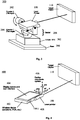
Figure 1 is a schematic, perspective view of an illustrative embodiment of a handheld positioning device comprising an inertial measurement unit (IMU) device used to determine relative position and orientation; -
Figure 2 is a schematic, perspective view of an illustrative embodiment of a mounted positioning device comprising a multi-axis gimbal with rotational sensors capable of measuring direction vector angles; -
Figure 3 is a schematic, perspective view of an illustrative embodiment of a mounted positioning device comprising an angle measurement gimbal and a 3-axis IMU; -
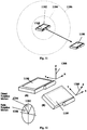
Figure 4 is a schematic, perspective view of an illustrative embodiment of a hand-held wireless device with attached laser pointer; -
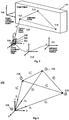
Figure 5 is a diagram of an illustrative embodiment of a target object local coordinate system, a handheld device local coordinate system, calibration points on the target object, and relative translation movement of the device; -
Figure 6 is a diagram of an illustrative embodiment of a vector diagram having vectors used for calculating an initial device location; -
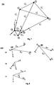
Figure 7 is a diagram of an illustrative embodiment of a vector diagram having vectors used for calculating an initial device location when the origin points are non-aligned; -
Figure 8 is a diagram of an illustrative embodiment of vector diagrams for a 3-point calibration process for determining the relative orientation of the device coordinate system; -
Figure 9 is a flowchart of an illustrative embodiment of a 3D localization process in a part of a location-based application; -
Figure 10 is a screen capture of an illustrative embodiment of a computer interface for a 3D localization application; -
Figure 11 is a diagram of an illustrative embodiment of a rate control method for determining translation in a virtual environment; and -
Figure 12 is a diagram of an illustrative embodiment of a rate control method for determining orientation in a virtual environment. - The following detailed description is merely illustrative in nature and is not intended to limit the embodiments of the invention or the application and uses of such embodiments.
- The following description refers to elements or nodes or features being "connected" or "coupled" together. As used herein, unless expressly stated otherwise, "connected" means that one element, node, or feature is directly joined to (or directly communicates with) another element, node, or feature, and not necessarily mechanically. Likewise, unless expressly stated otherwise, "coupled" means that one element, node, or feature is directly or indirectly joined to (or directly or indirectly communicates with) another clement/node/feature, and not necessarily mechanically. Similarly, unless expressly slated otherwise, "in communication" means that one element, node, or feature is directly or indirectly joined to (or directly or indirectly communicates with) another element/node/feature, and not necessarily mechanically. Thus, although the figures depict one possible arrangement of elements, additional intervening elements, devices, features, or components may be present in an embodiment of the depicted subject matter without departing from the scope of the present disclosure.
- Various technical terms used in this disclosure are defined as follows. Coordinate system refers to a frame of reference defined by three orthogonal directions (X, Y, Z); coordinate systems can be attached to moving and stationary objects. Cartesian coordinates refers to a rectangular (orthogonal) coordinate system. Local coordinates refers to a coordinate system associated with a specific object. Direction vector refers to a 3-dimensional measurement from an end position to an origin position described in terms of its X, Y, and Z components. Translation refers to linear or curvilinear motions that do not change the orientation of an object. Rotation refers to angular motions that change the orientation of the object without translating the object. Position refers specifically to the X, Y, and Z measurements of a point defined in a specific coordinate system. Orientation refers specifically to the measurement of the rotation of one coordinate system relative to another coordinate system. Rotation matrix refers to a 3x3 orthogonal matrix that describes the orientation of one coordinate system to another. Transformation matrix refers to a 4x4 homogeneous matrix that describes the relative position and orientation of one coordinate system to another (sometimes referred to as a transformation or matrix). Absolute motion refers to movement relative to a world coordinate system. Relative motion refers to movement of one coordinate system relative to another (sometimes referred to as local motion). Vector operations refers to direction vectors defined in the same coordinate system that can be added or subtracted, or multiplied by a rotation matrix to transform them from one coordinate system to another.
- A schematic view of one embodiment of a hand-held positioning device for spatial query shown in
Fig. 1 is an IMU-baseddevice 100. The IMU-baseddevice 100 comprises ahandle 102 for gripping the IMU-baseddevice 100, aselect button 104 positioned on or integrated into thehandle 102, a 6-axis inertial measuring unit (six-axis IMU 106), coupled to the top of thehandle 102. and alaser pointer 108 coupled to the six-axis IMU 106. The IMU-baseddevice 100 is held by a user (not shown) such that thelaser pointer 108 points towards atarget object 110. - In operation, a user points the IMU-based
device 100 at atarget object 110 and actuates theselect button 104, and the IMU-baseddevice 100 records the current state of the six-axis IMU 106. The six-axis IMU 106 provides the sensing components for a full 6-DOF inertial navigation system (INS). An INS is capable of continuous 6 degree-of-freedom (DOF) measurement, which includes 3-DOF for position and 3-DOF for orientation. The six-axis IMU 106 has accelerometers and gyros for measurement, of linear acceleration and angular velocity measurement, respectively. The data provided by the accelerometers and gyros, along with time measurements, is then numerically integrated to provide position and orientation data. A simple sighting device, in this embodiment alaser pointer 108, assists the user in pointing the IMU-baseddevice 100 at a desired location on thetarget object 1 10. In alternate embodiments, the pointing means can be a mechanical means, for example a physical feature of the IMU-baseddevice 100 itself, such as an edge, that is sight-aligned with the desired location on thetarget object 110, a light emitting means such as a projected light, a laser, an optical means such as a boresight affixed to the IMU-baseddevice 100, or a digital camera, for example with an accompanying screen or display for showing the picture from the direction pointed to by the digital camera. - In another embodiment, illustrated in
Fig. 2 , a gimbal-baseddevice 200 is used to measure the angular orientation of the gimbal-baseddevice 200. The gimbal-baseddevice 200 comprises amulti-axis gimbal 208 with atilt angle sensor 202 for measuring the tilt angle of thelaser pointer 108 relative to thebase 206, and apan angle sensor 204 for measuring the pan angle of thelaser pointer 108 relative to thebase 206. Together, the tilt andpan angle sensors laser pointer 108 of the gimbal-baseddevice 200. These tilt andpan angle sensors pan angle sensors axis IMU 106, but a potential downside of the gimbal-baseddevice 200 is that additional position translation can not be accommodated with this particular configuration, since measurement of relative translations from the initial position is not available solely from the tilt andpan angle sensors - Another embodiment, illustrated in
Fig. 3 , is ahybrid system 300. Thehybrid system 300 comprises the gimbal-based orientation measurement components of the gimbal-baseddevice 200 inFig. 1 combined with a 3-axislinear accelerometer unit 302 similar to the six-axis IMU 106 in the IMU-baseddevice 100 ofFig. 1 . Thehybrid system 300 provides high precision angle measurements while facilitating measurement of position changes. - Another embodiment, illustrated in
Fig. 4 , is an adaptedcommunications device 400. The adaptedcommunications device 400 comprises acommunications device 402 having a wireless or wired data connection and loaded with a software package for running a position determining application. Adisplay screen 404 provides a user interface and the selection trigger. Thecommunications device 402 can take the form of a cellphone, PDA, or similar wireless or wired device capable with a specified device coordinatesystem 406 and inertial-basedmeasurement sensors 408. Some current generation cell phones have integrated, general-purpose accelerometers (for example, the Apple® iPhone®), and future devices may also contain angular rate gyros, that make up the sensing components of an inertial measurement unit, or IMU, having multiple degrees of freedom. This is shown as the inertial-basedmeasurement sensors 408 embedded incommunications device 400. - In other embodiments, other types of accclerometer-gyro units may be externally coupled to
communications device 400. For example, the IMU-baseddevice 100, the gimbal-baseddevice 200, or thehybrid device 300 could be communicatively coupled tocommunications device 400 to provide position and orientation. With the proper numerical integration software, these general-purpose MEMS-based accelerometers and/or gyroscopes components can be used as the sensors for an inertial navigation system (INS) that functions similarly to dedicated IMU-based systems to measure position and rotation changes. - The
communications device 400 is shown with alaser pointer 108 used for sighting thetarget object 110. In alternative embodiments, a sighting scope, camera, video camera, or physical attributes of thecommunications device 400 itself can be used for sighting thetarget object 110. In those alternative embodiments, a crosshair or alignment markings (not shown) may facilitate proper sighting of thetarget object 110. - Referring now to
Fig. 5 , one embodiment of ahandheld device 500 comprises anIMU 502 and alaser pointer 108 as a simple sighting device. For purposes of illustration only, the system and method will be described using an airplane as thetarget object 110, even though the system and method are applicable to nearly anytarget object 110 such as a structure, vehicle, object, or the like. Thehandheld device 500 determines the current position and orientation of thehandheld device 500 in the local target coordinatesystem 506 of thetarget object 110, in this example an airplane. Knowing the exact position and orientation of thehandheld device 500 allows a user to retrieve information about parts and features of the airplane from a database that is stored in the local target coordinatesystem 506 of the airplane and facilitates construction, quality control, and maintenance functions to be performed to the airplane. This information may include, but is not limited to, numerical data, CAD/3D models, and images. - In various embodiments, this information regarding the airplane is displayed to the user on the
handheld device 500. For example, information regarding parts both visible to the user and occluded from the view of the user, for example hidden behind a panel, can be displayed on thehandheld device 500. In another embodiment, thehandheld device 500 determines the current position and orientation of the handheld device in the local coordinate system S06 of the airplane and presents instructions on the handheld device SUU to guide a user to the location of a desired feature, part, or position on the aircraft. In another embodiment real-time position and orientation data measured by thedevice 500 are used to move virtual objects or provide a virtual viewpoint in a 3D virtual environment or CAD application. In one embodiment, these applications run locally on thehandheld device 500; in another embodiment the handheld device supplies position and orientation information to a computer system (not shown) in communication with thehandheld device 500. In yet another embodiment, the position and orientation data from thehandheld device 500 is used to communicate data to a diagnostic system for thetarget object 110, for example a vehicle, to provide a display of real-time feedback of the diagnostic system's state, such as voltage, RPM, pressure, temperature, etc, In yet another embodiment, thedevice 500 uses die position and orientation data in communication with on-board system of atarget object 110 to select controllable components and set adjustable parameters of the component. - Continuing to refer to
Fig. 5 , a locating process determines the initial position of thehandheld device 500 relative to the target object. The locating process calibrates thehandheld device 500 and finds the current location of thehandheld device 500 relative to the airplane ortarget object 110. Thehandheld device 500 localization process used in this disclosure depends on determining direction vectors V from thehandheld device 500 to known positions orcalibration point target object 110, which are determined by using measurements of the handheld device's 500 relative orientation. Once calibrated in this way, the user then moves thehandheld device 500 and theIMU 502 tracks the relative positional changes between thecalibration position 508 and additional translatedpositions target object 110 and thehandheld device 500. - In some embodiments, the orientation of the
handheld device 500 relative to thetarget object 110 in not required during use, for example if only relative position data is required. In other embodiments, thehandheld device 500 also provides orientation data relative to thetarget object 110. An orientation process aligns thehandheld device 500 relative to thetarget object 110. When the orientation of thehandheld device 500 relative to thetarget object 110 is required, it can be determined in several different ways. For situations in which small movements from theoriginal calibration point 508 are needed, it may be satisfactory to visually align thehandheld device 500 with the axis of the airplane ortarget object 110. If more accurate tracking is needed for positions further away from thecalibration point 508, the user can align thehandheld device 500 with some known structure or marking on the airplane or target object 110 (for example a floor beam or stencil). For more general purpose determination of the relative orientation, a vector-based approach can be used, which will also be described later. If only theoriginal calibration position 508 is needed, then orienting and translating need not be performed. - Once the starting
position 508 and orientation of thehandheld device 500 have been established, the Cartesian position of thehandheld device 500 relative to thestarting point 508 can be updated in real-time as the user moves through or around the airplane ortarget object 110. For systems withfull IMU 502 capabilities, the position offsets are continuously measured by the positional measurement sensors and added to initial position 509; this is shown by the dashed line and additional points of interest or additional translatedpositions 510. 512 marked O' and O" inFig. 5 . - Continuing to refer to
Fig. 5 , the initial position calibration process uses the orientation sensors (e.g., 3-axis gyros or the gimbal device rotary tilt andpan angle sensors Figs. 2 and3 ) of theIMU 502 to measure the relative direction vectors from thecalibration position 508 to three known positions or threecalibration targets aircraft 110. The selection of the three calibration targets 514. 516, 518 are chosen so that there is a clear line of sight from thehandheld device 500, and so that the threecalibration targets laser pointer 108. In alternate embodiments, any visual alignment means such as a simple boresite or telescope would work. Thelaser pointer 108 is rigidly connected to theIMU 502, as shown inFigs. 1 through 5 , such that thelaser pointer 108 andIMU 502 move together. - Referring now to
Fig. 6 , thecalibration process 600 involves solving a system of three simultaneous linear equations defined by three vector loop equations.Fig. 6 shows the unknown location of the handheld device 500 (not shown) that will become thecalibration position 508, and the location of three known calibration points 514, 516, 518 on thetarget object 110. In this configuration, the vectors V12, V23 , and V31 on thetarget object 110 are known, as are unit vectors n1 , n2 , and n3, whose directions have been measured by theIMU 502, but the magnitudes of those vectors (d1, d2, and d3 ) are not known. - The derivation of the solution begins by defining three unique vector loop equations, shown in
Eqn 1. The unknown vectors V01 , V02, and V03 are related to the unit vectors n1 , n2 , and n3 through a scalar multiplication by the unknown magnitudes d1, d2, and d3 , as shown inEqn 2. The goal is to solve for d1, d2, and d3 and therefore find V01 , V02, and V03.

- After substitution there are three sets of three equations, shown in Eqns 3-5.


- From these, one equation is selected from each to create a non-singular set of equations and arranged into matrix form: M
A = B̂, as shown inEqn 6.
- The unknowns in column vector A are solved for by inverting M, and pre-multiplying both sides, resulting in:
A = M -1B . The values for A, which are d1, d2, and d3 , are then plugged intoEqn 2 to give the relative offset of thetarget object 110 to thehandheld device 500. - This formulation applies to both gyro-based angle measurement devices (e.g., an IMU-based
device 100, ahybrid device 300, and an adapted communications device 400) and gimbal-baseddevices 200. Also note that because only the relative pan and tilt angles of thehandheld device 500 are required for the calculations (i.e., without the roll angle), in some embodiments theIMU 502 only provides pan and tilt angle measurements (i.e., only has two degrees-of-freedom.) - When measuring the initial direction vectors, the method used to compute the
handheld device 500 position assumes a common intersection point for the three direction vectors, but sincedevice 500 is intended to be band-held, the origins of the three vectors may not intersect at a common location. During typical usage there will usually be small to moderate position offsets due to motions of the user which would cause inaccuracies in the local position computation. To adjust for these motions, the 3-axis accelerometer orIMU 502 data can be used at the time of the initial direction vector acquisition to measure relative translations between the three vector origins, O1, O2, and O3. - One option is to calculate the equivalent center of rotation by finding the average location of the points where the minimum distance between the direction vectors occurs. This relative offset will then be subtracted from the result of the calibration computation. Note that this is an approximate solution.
- A more accurate solution is a three
point calibration method 700 and involves solving the vector loop equations for a slightly different system configuration. Referring now toFig, 7 , the origin O1, O2, and O3 of each vector is in a different location, but the number of unknowns is the same, since the origins O1, O2, and O3 are offset by known amounts (from data measured by the accelerometers in the IMU 502). In the equations, this results in an additional known value included in the B vector ofEqn 6. From there, the solution process is the same as described for the system where the origins O1, O2, and O3 intersect. - In another embodiment of a three point calibration method in which distance along the aim point vector is not measured directly, the orientation can be derived in a second step using the position solution determined in the initial relative positioning process. For this
reconstructed orientation process 800, the relative position is used to generate direction vectors of the proper length from the three unit vectors measured by the handheld device. This allows the target points to be reconstructed in the handheld device's coordinate system, which are labeled: PA1, PA2, and PA3, in the vector diagrams ofFig. 8 . From this, the relative orientation between the coordinate systems can be determined using the process described below:


- In the formulation above:
-
V A12 is the vector in coordinate system A created from pointsP̅ A1 andP̅ A2 (i.e..V A12 =P A2 -P A3). - Vectors
V B3,V B32,V B13 follow the same format. -
n A andn B are the vector normals created from the vector cross products -
k 1 andk 2 are axes of rotation - θ 1 and θ 2 are rotation angles about axes
k 1 andk 2, respectively - R 1, R 2, and R 12 are 3x3 symmetric rotation matrices, and
- f1 () is the function which generates a 3x3 rotation matrix from the angle-axis definition described below (as shown in "Introduction to Robotics; Mechanics and Control", 3rd ed. by John J. Craig, published by Prentice Hall in 2004):

- The
IMU 502 measures the rate of change in angle (from three gyros) and the linear acceleration (from three accelerometers). The raw data from the gyros is integrated once to produce the angles, and the data from the accelerometers is integrated twice to produce position, as shown inEqns 7 and 8.

- The acceleration data must be transformed into a stationary coordinate system by pre-multiplication of a rotation matrix created from the gyro data before it can be used for this task. The data may also be filtered to reduce noise.
IMUs 502, such as the six-axis IMU 106, tend to drift in both position and orientation, which means that re-calibration of thehandheld device 500 to the target object will be necessary after some time. TheseIMU 502 issues are common to inertial navigation systems of this type, not specific to this invention disclosure but have been included here for completeness. In other embodiments, applications running on, or in communication with, thehandheld device 500 use the acceleration and/or velocity data for additional purposes and tasks. - Rotary sensors in a 2-
axis gimbal 208 move measure relative to the base in pan (θ1) and tilt (θ2) angle, which can be converted into the direction vectors described earlier by using Equation 9.
- For some applications it may be useful to have the laser beam emanate from the
handheld device 500 in a different direction, for example along the y-axis or negative z-axis of thehandheld device 500. In these types of embodiments, redirection of the beam can be accomplished by physically mounting thelaser pointer 108 in a new fixed position, or by using a beam splitter or mirror placed in the path of the laser beam from thelaser pointer 108. - In some applications is may be useful to trace a shape while continuously recording the path, for example a wire, tube, or edge. In one such embodiment, a physical guide (not shown) of known dimensions is attached to the handheld device 500 (for example, an extension with a hook) that allows the user to easily constrain motion to follow the path along the
target 110 as the user moves thehandheld device 500. - Referring now to
Fig. 9 , one embodiment of a system comprises thelocalization process 900, auser interface 902, and infrastructure to communicate with an application that uses location data (e.g., a 3D database or visualization server). In this application, the user needs local position data in order to extract a location specific result from aspatial database 904. Thelocalization sub-system 900 comprises a 3-DOF orientation sensor or a 6-DOF inertial measurement device (e.g., IMU 502), a pointing device (e.g, laser pointer 108), andposition calculation software 906. Referring toFig. 10 , one embodiment of theuser application interface 902 is illustrated. - The
handheld device 500 utilizes anIMU 502 to track position, allowing thehandheld device 500 to be used indoors or other places where GPS coverage is poor or unavailable. TheIMU 502 in or attached to thehandheld device 500 is self-contained, eliminating the need to first put additional infrastructure in place prior to using a positioning system, for example the perimeter of transmitters/receivers commonly used to enable RFID based positioning systems. TheIMU 502 also provides positioning data faster than either OPS or RFID, allowing for much finer granularity of movement. TheIMU 502 further eliminates the possibility of transmitter-to-receiver errors that are possible with GPS and RFID based systems, such as low signal strength, signal outages, local signal blocking, multipath errors, and other potential signal path distortions. Signal path distortions can be exacerbated by the presence of large quantities of metal, such as those found in airplanes, in ways that can be hard to predict and difficult to compensate for. TheIMU 502 improves position accuracy and reliability because it does not rely on external signals that can be lost or distorted. Further, thehandheld device 500 can generally be produced at a lower price point because it does not require this ancillary equipment. - In some embodiments, the
handheld device 500 is configured in a form factor that is small and light enough to be held and, in some embodiments, used with one band. The handheld device is available for immediate use once power is turned on. A simple calibration procedure reduces the setup time compared with many current commercially available positioning systems. This simple and fast calibration allows mechanics, technicians, inspectors, and others to use thehandheld device 500 for everyday applications where the use of more complex or expensive positioning systems might not be justifiable. - The cost and ease of use of the
handheld device 500 allows it to be used in any number of alternative applications. For example, tourists equipped with thehandheld device 500 could navigate around museums and historical sites on self-guided tours, allowing them to point at specific points of interest and retrieve related information about the item being pointed at. Visitors to campuses or facilities can use thehandheld device 500 to receive directions, even indoors where it might be difficult to receive GPS signals and impractical to set up RFID transmitters/receivers. The database that thehandheld device 500 accesses can describe a virtual object, for example an airplane under construction. Therefore, when partnered with a video display, thehandheld device 500 can be used during factory tours or trade shows to present virtual tours to potential customers. - In an alternative embodiment, not being part of the claimed invention, the
handheld device 500 can be set to a specified position directly, without taking measurements or performing the calibration procedure. For example, the handheld device's 500 position and orientation can be manually or automatically entered using fixed index marks in the target object's 110 environment, for example from previous device's calibrations or by using landmarks with known position and orientation. This allows users to return thehandheld device 500 to a known location and pick up where they (or someone else) left off. - In another embodiment, not being part of the claimed invention, direct entry of position and orientation into the
handheld device 500 allows the user to simulate interaction with thetarget object 110 from a remote location. In this simulation mode there are additional motion control methods. Additionally, instead of a 1:1 mapping of IMU translation and rotation from the physical world to the CAD/3D virtual environment, thehandheld device 500 is configured to scale motions to allow a small motion of thehandheld device 500 to represent a large motion in the virtual environment, or a large motion of thehandheld device 500 can be scaled to small motion in the virtual environment. Therefore, thehandheld device 500 can be used to virtually navigate in spaces much smaller, much larger, or different than that of the real world. For example, thehandheld device 500 in conjunction with a display can allow an educator to take students on a virtual tour of something as large as the known universe, or as small as atoms, by moving thehandheld device 500 during a lecture in a classroom. In this embodiment, the position of thehandheld device 500 can be indexed in an equivalent way to how a user picks up a computer mouse once the physical computer mouse reaches the edge of the mouse pad and repositions computer mouse to get more space to continue moving the cursor on the screen. For thehandheld device 500, the indexing is in three to six dimensions instead of just two dimensions as is standard with a computer mouse. - In one embodiment, not being part of the claimed invention" translation movements in the virtual environment use rate (velocity) control instead of, or in addition to, direct position control. Referring now to
Fig. 11 , thedevice 1100 is initially located at aninitial position 1102. Any movement of thedevice 1100 within afirst radius 1104 of theinitial position 1102 produces direct positioning motion. Any movement of thedevice 1100 outside of thefirst radius 1104, but inside of asecond radius 1106, causes continuous motion at a constant velocity along a heading away from theinitial position 1102 until the user returns thedevice 1100 to inside of thefirst radius 1104 or re-indexes thedevice 1100 to a new initial position (not shown). Moving thedevice 1100 outside of thesecond radius 1106 causes acceleration in that direction at an increasingly faster rate. - In another embodiment, not being part of the claimed invention, orientation changes in the virtual environment use a similar rate control methodology to that described above for translation movements. Referring now to
Fig. 12 , when the vertical axis (Z) 1208 of thedevice 1100 moves within theinner wedge region 1204 relative to theinitial orientation 1202, motion in the virtual environment is in the direct orientation control mode. When thevertical axis 1208 of thedevice 1100 is moved further away from theinitial orientation 1202 to the outer wedge region 1206 a rate control method is enabled that causes the angle to continue to increase even when thedevice 1100 is held stationary. To stop the motion, the user returns thevertical axis 1208 of thedevice 1100 to theinner wedge region 1204 near theinitial orientation 1202, or applies indexing. - In both rate control embodiments, not being put of the claimed invention, rate motion control, which is a measure of translational or rotational velocity, can be used directly by the
handheld device 1100 or sent to a remote application for other uses. Similarly, acceleration data can be used directly by thehandheld device 1100 or sent to a remote application for other uses. - Various embodiments of the invention shown in the drawings and described above are exemplary of numerous embodiments that may be within the scope of the appended claims. It is contemplated that numerous other configurations of a handheld device capable of determining the position and orientation of the handheld device relative to a known object may be created taking advantage of the disclosed approach. It is the applicant's intention that the scope of the patent issuing herefrom will be limited only by the scope of the appended claims.
Claims (11)
- A system for determining spatial position relative to a target object (110), said target object having three non co-linear calibration points, the location of which on the target object is known, the system comprising:an actuator for triggering a selection indication when said system is oriented at a calibration point on said object;an orientation detector (200) for providing an orientation indication of the system when said selection indication is triggered;a spatial position detector (302) for providing a plurality of positional movement indications of the system, said spatial position detector comprising an inertial measurement unit;characterized bya processor adapted to calibrate an initial position of the system relative to the target object using the known location of the calibration points and three orientation indications, each orientation indication being for a different calibration point, and to track a current position of the system using said plurality of positional movement indications; andan output means for indicating said initial position and said current position relative to said target object.
- The system of claim 1, further comprising a pointing means (108) for pointing at a calibration point on the target object, the orientation detector providing an orientation indication of the pointing means and being selected from the group consisting of a mechanical pointing means, a light emitting means, a laser, an optical means, and a digital imaging means.
- The system of claim 1, wherein said orientation detector comprises a pointing means and a gimbal having a pan angle sensor and a tilt angle sensor, the pointing means and gimbal being in physical communication with each other.
- The system of claim 1, wherein said inertial measurement unit is selected from the group consisting of a two degree of freedom inertial measurement unit, a three degree of freedom inertial measurement unit, a four degree of freedom inertial measurement unit, a five degree of freedom inertial measurement unit, and a six degree of freedom inertial measurement unit.
- The system of claim 1, wherein said processor is adapted to calibrate an initial position of the apparatus relative to a target object using a plurality of said orientation indication and said plurality of positional movement indications.
- The system of claim 1, wherein said system is handheld.
- The system of claim 1, wherein said system is a wireless communications device.
- A method of determining the spatial position relative to a target object, the method comprising:(a) calibrating a device to determine an initial position of said device relative to a target object said target object having three non co-linear calibration points, the location on the target of which is known, said calibrating further comprising:(i) pointing a pointing means of said device at a calibration point of said target object;(ii) sensing said orientation of said device during said pointing operation;(iii)repeating said steps (i) and (ii) for asaid three calibration points; and(iv) calculating said initial position of said device relative to said target object using said known location of calibration points and said orientation of said device for said three calibration points pointed at by said pointing means on said device, and(b) moving said device to a new position;(c) sensing said moving operation using a sensor in said device, said sensor comprising an inertial measurement unit; and(d) calculating said new position of said device using an information from said sensor(e) outputting said new position of said device.
- The method of claim 8, wherein said coordinate system of said target object is different than a coordinate system of said device.
- The method of claim 8, wherein said step (a)(ii) further comprises sensing a movement of said device between a previous pointing operation and a current pointing operation for each pointing operation, and said step (a)(iv) calculates said initial position of said device relative to said known object using said known location, said orientation of said device for said plurality of features pointed at by said pointing means on said device, and said movement of said device between each said pointing operation.
- The method of claim 9, further comprising displaying an information regarding said known object based at least in part upon said new position and a new orientation of said device;
wherein said information is retrieved using said new position of said device in the coordinate system of said known object.
Applications Claiming Priority (2)
| Application Number | Priority Date | Filing Date | Title |
|---|---|---|---|
| US12/259,947 US8138938B2 (en) | 2008-10-28 | 2008-10-28 | Hand-held positioning interface for spatial query |
| PCT/US2009/062441 WO2010053809A1 (en) | 2008-10-28 | 2009-10-28 | Hand-held positioning interface for spatial query |
Publications (2)
| Publication Number | Publication Date |
|---|---|
| EP2350562A1 EP2350562A1 (en) | 2011-08-03 |
| EP2350562B1 true EP2350562B1 (en) | 2018-09-26 |
Family
ID=41665019
Family Applications (1)
| Application Number | Title | Priority Date | Filing Date |
|---|---|---|---|
| EP09752947.3A Active EP2350562B1 (en) | 2008-10-28 | 2009-10-28 | Positioning interface for spatial query |
Country Status (4)
| Country | Link |
|---|---|
| US (1) | US8138938B2 (en) |
| EP (1) | EP2350562B1 (en) |
| JP (1) | JP5722224B2 (en) |
| WO (1) | WO2010053809A1 (en) |
Families Citing this family (64)
| Publication number | Priority date | Publication date | Assignee | Title |
|---|---|---|---|---|
| CN101480061B (en) * | 2006-06-23 | 2011-07-20 | Nxp股份有限公司 | Orientation sensing in a multi part device |
| US9423250B1 (en) | 2009-12-17 | 2016-08-23 | The Boeing Company | Position measurement correction using loop-closure and movement data |
| US8279412B2 (en) * | 2009-12-17 | 2012-10-02 | The Boeing Company | Position and orientation determination using movement data |
| US9149929B2 (en) | 2010-05-26 | 2015-10-06 | The Boeing Company | Methods and systems for inspection sensor placement |
| US20120120230A1 (en) * | 2010-11-17 | 2012-05-17 | Utah State University | Apparatus and Method for Small Scale Wind Mapping |
| FR2972012B1 (en) * | 2011-02-25 | 2013-03-15 | Commissariat Energie Atomique | METHOD FOR ASSISTING THE PLACEMENT OF CONSTRUCTION ELEMENTS OF A CIVIL ENGINEERING WORK |
| US8447805B2 (en) | 2011-02-28 | 2013-05-21 | The Boeing Company | Distributed operation of a local positioning system |
| JP5670798B2 (en) * | 2011-03-30 | 2015-02-18 | フェリカネットワークス株式会社 | Communication terminal, communication method, and program |
| US8407111B2 (en) * | 2011-03-31 | 2013-03-26 | General Electric Company | Method, system and computer program product for correlating information and location |
| US9273990B1 (en) * | 2011-09-11 | 2016-03-01 | The Boeing Company | Aircraft repair fixture |
| US8768560B2 (en) * | 2011-10-04 | 2014-07-01 | Webtech Wireless Inc. | Method and system for performing calibration of an accelerometer of a telematics device during installation in a vehicle |
| US8556162B2 (en) * | 2011-11-21 | 2013-10-15 | The Boeing Company | Component programming system |
| US10268761B2 (en) | 2011-12-21 | 2019-04-23 | The Boeing Company | Panoptic visualization document collection |
| US9104760B2 (en) | 2011-12-21 | 2015-08-11 | The Boeing Company | Panoptic visualization document database management |
| US9524342B2 (en) | 2011-12-21 | 2016-12-20 | The Boeing Company | Panoptic visualization document navigation |
| US20130238511A1 (en) * | 2012-03-08 | 2013-09-12 | Airbus Operations Sas | System and method for end-of-life processing of an airframe |
| US9495476B2 (en) | 2012-03-23 | 2016-11-15 | The Boeing Company | Panoptic visualization of an illustrated parts catalog |
| US9058681B2 (en) | 2012-06-01 | 2015-06-16 | The Boeing Company | Sensor-enhanced localization in virtual and physical environments |
| US10380469B2 (en) * | 2012-07-18 | 2019-08-13 | The Boeing Company | Method for tracking a device in a landmark-based reference system |
| US10268662B2 (en) | 2012-09-10 | 2019-04-23 | The Boeing Company | Panoptic visualization of a document according to the structure thereof |
| US10275428B2 (en) | 2012-09-25 | 2019-04-30 | The Boeing Company | Panoptic visualization document differencing |
| DE102012217282B4 (en) * | 2012-09-25 | 2023-03-02 | Trimble Jena Gmbh | Method and device for assigning measuring points to a set of fixed points |
| US10824680B2 (en) | 2012-10-02 | 2020-11-03 | The Boeing Company | Panoptic visualization document access control |
| KR101416364B1 (en) | 2012-10-15 | 2014-07-08 | 현대자동차 주식회사 | Pointing navigation device and the method, pointing navigation system for a personal mobility using the same |
| US9875220B2 (en) | 2012-11-09 | 2018-01-23 | The Boeing Company | Panoptic visualization document printing |
| US9665557B2 (en) | 2013-01-28 | 2017-05-30 | The Boeing Company | Panoptic visualization of elements of a complex system using localization of a point on a physical instance of the complex system |
| US9734625B2 (en) | 2013-01-28 | 2017-08-15 | The Boeing Company | Panoptic visualization of a three-dimensional representation of a complex system |
| US9858245B2 (en) | 2013-01-28 | 2018-01-02 | The Boeing Company | Panoptic visualization of elements of a complex system using a model viewer |
| US8887993B2 (en) | 2013-04-23 | 2014-11-18 | The Boeing Company | Barcode access to electronic resources for complex system parts |
| US9098593B2 (en) | 2013-04-23 | 2015-08-04 | The Boeing Company | Barcode access to electronic resources for lifecycle tracking of complex system parts |
| FR3005819B1 (en) * | 2013-05-15 | 2015-05-01 | Thales Sa | MAINTENANCE SUPPORT DEVICE AND MAINTENANCE METHOD USING SUCH A DEVICE |
| US9430822B2 (en) | 2013-06-14 | 2016-08-30 | Microsoft Technology Licensing, Llc | Mobile imaging platform calibration |
| JP6320000B2 (en) * | 2013-11-22 | 2018-05-09 | 株式会社日立システムズ | Spatial coordinate measurement method, spatial coordinate measurement system, spatial coordinate measurement program, and laser pointer |
| US9355498B2 (en) | 2014-06-19 | 2016-05-31 | The Boeing Company | Viewpoint control of a display of a virtual product in a virtual environment |
| US9489597B2 (en) | 2014-08-21 | 2016-11-08 | The Boeing Company | Visualization and analysis of a topical element of a complex system |
| US9841870B2 (en) | 2014-08-21 | 2017-12-12 | The Boeing Company | Integrated visualization and analysis of a complex system |
| US10191997B2 (en) | 2014-08-21 | 2019-01-29 | The Boeing Company | Visualization and diagnostic analysis of interested elements of a complex system |
| JP6193195B2 (en) | 2014-09-17 | 2017-09-06 | 株式会社東芝 | Movement support apparatus, method and program |
| WO2016146817A1 (en) * | 2015-03-19 | 2016-09-22 | Meloq Ab | Method and device for anatomical angle measurement |
| US9924103B2 (en) * | 2015-04-09 | 2018-03-20 | The Boeing Company | Automated local positioning system calibration using optically readable markers |
| FR3043815A1 (en) * | 2015-11-13 | 2017-05-19 | Airbus Operations Sas | METHOD FOR DISPLAYING IMAGES CORRESPONDING TO AN OUTER ENVIRONMENT OF THE VEHICLE ON A MOBILE DISPLAY DEVICE EMBEDDED IN A VEHICLE |
| US9892558B2 (en) * | 2016-02-19 | 2018-02-13 | The Boeing Company | Methods for localization using geotagged photographs and three-dimensional visualization |
| JP6987797B2 (en) * | 2016-03-11 | 2022-01-05 | カールタ インコーポレイテッド | Laser scanner with real-time online egomotion estimation |
| US11573325B2 (en) | 2016-03-11 | 2023-02-07 | Kaarta, Inc. | Systems and methods for improvements in scanning and mapping |
| US10989542B2 (en) | 2016-03-11 | 2021-04-27 | Kaarta, Inc. | Aligning measured signal data with slam localization data and uses thereof |
| US11567201B2 (en) | 2016-03-11 | 2023-01-31 | Kaarta, Inc. | Laser scanner with real-time, online ego-motion estimation |
| US10155596B2 (en) | 2016-06-06 | 2018-12-18 | The Boeing Company | Three-dimensional aircraft inspection system for layout of passenger accommodations |
| US10274924B2 (en) | 2016-06-30 | 2019-04-30 | Sharp Laboratories Of America, Inc. | System and method for docking an actively stabilized platform |
| CN113727023A (en) * | 2017-01-24 | 2021-11-30 | 深圳市大疆灵眸科技有限公司 | Control method and system of pan-tilt and computer readable storage medium |
| CA3059209A1 (en) | 2017-04-27 | 2018-11-01 | Magic Leap, Inc. | Light-emitting user input device |
| US10627475B2 (en) * | 2017-05-05 | 2020-04-21 | The Boeing Company | Pose estimation using radio frequency identification (RFID) tags |
| DE102017213555A1 (en) | 2017-08-04 | 2019-02-07 | Siemens Aktiengesellschaft | An apparatus and method for location-based location of a location on a surface of an object |
| JP7018286B2 (en) * | 2017-10-04 | 2022-02-10 | Ihi運搬機械株式会社 | Crane suspension member guidance system |
| WO2019099605A1 (en) | 2017-11-17 | 2019-05-23 | Kaarta, Inc. | Methods and systems for geo-referencing mapping systems |
| CN113835437A (en) * | 2018-01-31 | 2021-12-24 | 深圳市大疆创新科技有限公司 | Movable platform control method and device |
| WO2019165194A1 (en) | 2018-02-23 | 2019-08-29 | Kaarta, Inc. | Methods and systems for processing and colorizing point clouds and meshes |
| WO2019236588A1 (en) | 2018-06-04 | 2019-12-12 | The Research Foundation For The State University Of New York | System and method associated with expedient determination of location of one or more object(s) within a bounded perimeter of 3d space based on mapping and navigation to a precise poi destination using a smart laser pointer device |
| US11094221B2 (en) * | 2018-06-21 | 2021-08-17 | University Of Utah Research Foundation | Visual guidance system and method for posing a physical object in three dimensional space |
| US10800550B2 (en) | 2018-06-21 | 2020-10-13 | The Boeing Company | Positioning enhancements to localization process for three-dimensional visualization |
| WO2020009826A1 (en) | 2018-07-05 | 2020-01-09 | Kaarta, Inc. | Methods and systems for auto-leveling of point clouds and 3d models |
| EP3623996A1 (en) * | 2018-09-12 | 2020-03-18 | Aptiv Technologies Limited | Method for determining a coordinate of a feature point of an object in a 3d space |
| CN109461295B (en) * | 2018-12-07 | 2021-06-11 | 连尚(新昌)网络科技有限公司 | Household alarm method and equipment |
| US11029369B1 (en) * | 2019-01-26 | 2021-06-08 | Alken Inc. | Self-leveling magnetic source |
| US10929670B1 (en) | 2019-10-21 | 2021-02-23 | The Boeing Company | Marker-to-model location pairing and registration for augmented reality applications |
Family Cites Families (20)
| Publication number | Priority date | Publication date | Assignee | Title |
|---|---|---|---|---|
| JPS5942410A (en) * | 1982-09-02 | 1984-03-09 | Nec Corp | Self-position calculating method |
| US4806936A (en) * | 1986-06-20 | 1989-02-21 | Hughes Aircraft Company | Method of determining the position of multiple targets using bearing-only sensors |
| US5150310A (en) * | 1989-08-30 | 1992-09-22 | Consolve, Inc. | Method and apparatus for position detection |
| JP3274290B2 (en) * | 1994-09-19 | 2002-04-15 | 三菱電機株式会社 | Video display device and video display system |
| JPH10274526A (en) * | 1997-03-31 | 1998-10-13 | Taisei Corp | Position coordinate detection device and surveying device therewith |
| FR2770317B1 (en) * | 1997-10-24 | 2000-12-08 | Commissariat Energie Atomique | METHOD FOR CALIBRATING THE ORIGINAL POSITION AND ORIENTATION OF ONE OR MORE MOBILE CAMERAS AND ITS APPLICATION TO MEASURING THE THREE-DIMENSIONAL POSITION OF FIXED OBJECTS |
| US6671058B1 (en) * | 1998-03-23 | 2003-12-30 | Leica Geosystems Ag | Method for determining the position and rotational position of an object |
| GB2353659A (en) | 1998-05-15 | 2001-02-28 | Tricorder Technology Plc | Method and apparatus for 3D representation |
| BE1014137A6 (en) * | 2001-04-24 | 2003-05-06 | Krypton Electronic Eng Nv | Method and device for verification and identification of a measuring device. |
| EP1447644A1 (en) * | 2003-02-14 | 2004-08-18 | Metronor ASA | Measurement of spatial coordinates |
| JP4002211B2 (en) * | 2003-05-23 | 2007-10-31 | 三菱電機株式会社 | Field work support device |
| US20070010925A1 (en) * | 2003-09-02 | 2007-01-11 | Komatsu Ltd. | Construction target indicator device |
| DE10359415A1 (en) | 2003-12-16 | 2005-07-14 | Trimble Jena Gmbh | Method for calibrating a surveying device |
| JP2005326275A (en) | 2004-05-14 | 2005-11-24 | Canon Inc | Information processing method and device |
| JP2006155195A (en) * | 2004-11-29 | 2006-06-15 | Yaskawa Electric Corp | Self-position identification device of mobile body and self-position identification method of mobile body |
| EP1669776A1 (en) * | 2004-12-11 | 2006-06-14 | Leica Geosystems AG | Handheld distance measuring apparatus and a method therefore |
| JP2008261755A (en) | 2007-04-12 | 2008-10-30 | Canon Inc | Information processing apparatus and information processing method |
| US8044991B2 (en) * | 2007-09-28 | 2011-10-25 | The Boeing Company | Local positioning system and method |
| US7859655B2 (en) * | 2007-09-28 | 2010-12-28 | The Boeing Company | Method involving a pointing instrument and a target object |
| US20100225498A1 (en) * | 2009-03-05 | 2010-09-09 | Searete Llc, A Limited Liability Corporation | Postural information system and method |
-
2008
- 2008-10-28 US US12/259,947 patent/US8138938B2/en active Active
-
2009
- 2009-10-28 EP EP09752947.3A patent/EP2350562B1/en active Active
- 2009-10-28 JP JP2011533437A patent/JP5722224B2/en active Active
- 2009-10-28 WO PCT/US2009/062441 patent/WO2010053809A1/en active Application Filing
Non-Patent Citations (1)
| Title |
|---|
| None * |
Also Published As
| Publication number | Publication date |
|---|---|
| WO2010053809A1 (en) | 2010-05-14 |
| EP2350562A1 (en) | 2011-08-03 |
| US20100102980A1 (en) | 2010-04-29 |
| JP2012507011A (en) | 2012-03-22 |
| US8138938B2 (en) | 2012-03-20 |
| JP5722224B2 (en) | 2015-05-20 |
Similar Documents
| Publication | Publication Date | Title |
|---|---|---|
| EP2350562B1 (en) | Positioning interface for spatial query | |
| US11035659B2 (en) | Inertial dimensional metrology | |
| US10665012B2 (en) | Augmented reality camera for use with 3D metrology equipment in forming 3D images from 2D camera images | |
| US10585167B2 (en) | Relative object localization process for local positioning system | |
| EP2869024B1 (en) | Three-dimensional measuring method and surveying system | |
| US7742176B2 (en) | Method and system for determining the spatial position of a hand-held measuring appliance | |
| US8060344B2 (en) | Method and system for automatically performing a study of a multidimensional space | |
| US8044991B2 (en) | Local positioning system and method | |
| US8773465B2 (en) | Methods and apparatus for providing navigational information associated with locations of objects | |
| CA2811444C (en) | Geodetic survey system having a camera integrated in a remote control unit | |
| JP4607095B2 (en) | Method and apparatus for image processing in surveying instrument | |
| JP6823482B2 (en) | 3D position measurement system, 3D position measurement method, and measurement module | |
| EP3734222A1 (en) | Coordinate measuring and/or stake out device | |
| CN211601925U (en) | Angular deviation measuring system | |
| CN111504344B (en) | Calibration system and method for calibrating non-contact attitude measurement equipment | |
| Zheng et al. | Using optical projection in close-range photogrammetry for 6DOF sensor positioning | |
| GB2511426A (en) | Apparatus for locating a remote point of interest |
Legal Events
| Date | Code | Title | Description |
|---|---|---|---|
| PUAI | Public reference made under article 153(3) epc to a published international application that has entered the european phase |
Free format text: ORIGINAL CODE: 0009012 |
|
| 17P | Request for examination filed |
Effective date: 20110516 |
|
| AK | Designated contracting states |
Kind code of ref document: A1 Designated state(s): AT BE BG CH CY CZ DE DK EE ES FI FR GB GR HR HU IE IS IT LI LT LU LV MC MK MT NL NO PL PT RO SE SI SK SM TR |
|
| DAX | Request for extension of the european patent (deleted) | ||
| 17Q | First examination report despatched |
Effective date: 20140909 |
|
| GRAP | Despatch of communication of intention to grant a patent |
Free format text: ORIGINAL CODE: EPIDOSNIGR1 |
|
| INTG | Intention to grant announced |
Effective date: 20180410 |
|
| GRAS | Grant fee paid |
Free format text: ORIGINAL CODE: EPIDOSNIGR3 |
|
| GRAA | (expected) grant |
Free format text: ORIGINAL CODE: 0009210 |
|
| AK | Designated contracting states |
Kind code of ref document: B1 Designated state(s): AT BE BG CH CY CZ DE DK EE ES FI FR GB GR HR HU IE IS IT LI LT LU LV MC MK MT NL NO PL PT RO SE SI SK SM TR |
|
| REG | Reference to a national code |
Ref country code: GB Ref legal event code: FG4D |
|
| REG | Reference to a national code |
Ref country code: CH Ref legal event code: EP |
|
| REG | Reference to a national code |
Ref country code: AT Ref legal event code: REF Ref document number: 1046541 Country of ref document: AT Kind code of ref document: T Effective date: 20181015 |
|
| REG | Reference to a national code |
Ref country code: IE Ref legal event code: FG4D |
|
| REG | Reference to a national code |
Ref country code: DE Ref legal event code: R096 Ref document number: 602009054749 Country of ref document: DE Ref country code: FR Ref legal event code: PLFP Year of fee payment: 10 |
|
| REG | Reference to a national code |
Ref country code: NL Ref legal event code: MP Effective date: 20180926 |
|
| PG25 | Lapsed in a contracting state [announced via postgrant information from national office to epo] |
Ref country code: LT Free format text: LAPSE BECAUSE OF FAILURE TO SUBMIT A TRANSLATION OF THE DESCRIPTION OR TO PAY THE FEE WITHIN THE PRESCRIBED TIME-LIMIT Effective date: 20180926 Ref country code: NO Free format text: LAPSE BECAUSE OF FAILURE TO SUBMIT A TRANSLATION OF THE DESCRIPTION OR TO PAY THE FEE WITHIN THE PRESCRIBED TIME-LIMIT Effective date: 20181226 Ref country code: GR Free format text: LAPSE BECAUSE OF FAILURE TO SUBMIT A TRANSLATION OF THE DESCRIPTION OR TO PAY THE FEE WITHIN THE PRESCRIBED TIME-LIMIT Effective date: 20181227 Ref country code: FI Free format text: LAPSE BECAUSE OF FAILURE TO SUBMIT A TRANSLATION OF THE DESCRIPTION OR TO PAY THE FEE WITHIN THE PRESCRIBED TIME-LIMIT Effective date: 20180926 Ref country code: SE Free format text: LAPSE BECAUSE OF FAILURE TO SUBMIT A TRANSLATION OF THE DESCRIPTION OR TO PAY THE FEE WITHIN THE PRESCRIBED TIME-LIMIT Effective date: 20180926 Ref country code: BG Free format text: LAPSE BECAUSE OF FAILURE TO SUBMIT A TRANSLATION OF THE DESCRIPTION OR TO PAY THE FEE WITHIN THE PRESCRIBED TIME-LIMIT Effective date: 20181226 |
|
| REG | Reference to a national code |
Ref country code: LT Ref legal event code: MG4D |
|
| PG25 | Lapsed in a contracting state [announced via postgrant information from national office to epo] |
Ref country code: LV Free format text: LAPSE BECAUSE OF FAILURE TO SUBMIT A TRANSLATION OF THE DESCRIPTION OR TO PAY THE FEE WITHIN THE PRESCRIBED TIME-LIMIT Effective date: 20180926 Ref country code: HR Free format text: LAPSE BECAUSE OF FAILURE TO SUBMIT A TRANSLATION OF THE DESCRIPTION OR TO PAY THE FEE WITHIN THE PRESCRIBED TIME-LIMIT Effective date: 20180926 |
|
| REG | Reference to a national code |
Ref country code: AT Ref legal event code: MK05 Ref document number: 1046541 Country of ref document: AT Kind code of ref document: T Effective date: 20180926 |
|
| PG25 | Lapsed in a contracting state [announced via postgrant information from national office to epo] |
Ref country code: IT Free format text: LAPSE BECAUSE OF FAILURE TO SUBMIT A TRANSLATION OF THE DESCRIPTION OR TO PAY THE FEE WITHIN THE PRESCRIBED TIME-LIMIT Effective date: 20180926 Ref country code: EE Free format text: LAPSE BECAUSE OF FAILURE TO SUBMIT A TRANSLATION OF THE DESCRIPTION OR TO PAY THE FEE WITHIN THE PRESCRIBED TIME-LIMIT Effective date: 20180926 Ref country code: CZ Free format text: LAPSE BECAUSE OF FAILURE TO SUBMIT A TRANSLATION OF THE DESCRIPTION OR TO PAY THE FEE WITHIN THE PRESCRIBED TIME-LIMIT Effective date: 20180926 Ref country code: NL Free format text: LAPSE BECAUSE OF FAILURE TO SUBMIT A TRANSLATION OF THE DESCRIPTION OR TO PAY THE FEE WITHIN THE PRESCRIBED TIME-LIMIT Effective date: 20180926 Ref country code: RO Free format text: LAPSE BECAUSE OF FAILURE TO SUBMIT A TRANSLATION OF THE DESCRIPTION OR TO PAY THE FEE WITHIN THE PRESCRIBED TIME-LIMIT Effective date: 20180926 Ref country code: IS Free format text: LAPSE BECAUSE OF FAILURE TO SUBMIT A TRANSLATION OF THE DESCRIPTION OR TO PAY THE FEE WITHIN THE PRESCRIBED TIME-LIMIT Effective date: 20190126 Ref country code: ES Free format text: LAPSE BECAUSE OF FAILURE TO SUBMIT A TRANSLATION OF THE DESCRIPTION OR TO PAY THE FEE WITHIN THE PRESCRIBED TIME-LIMIT Effective date: 20180926 Ref country code: AT Free format text: LAPSE BECAUSE OF FAILURE TO SUBMIT A TRANSLATION OF THE DESCRIPTION OR TO PAY THE FEE WITHIN THE PRESCRIBED TIME-LIMIT Effective date: 20180926 Ref country code: PL Free format text: LAPSE BECAUSE OF FAILURE TO SUBMIT A TRANSLATION OF THE DESCRIPTION OR TO PAY THE FEE WITHIN THE PRESCRIBED TIME-LIMIT Effective date: 20180926 |
|
| PG25 | Lapsed in a contracting state [announced via postgrant information from national office to epo] |
Ref country code: SK Free format text: LAPSE BECAUSE OF FAILURE TO SUBMIT A TRANSLATION OF THE DESCRIPTION OR TO PAY THE FEE WITHIN THE PRESCRIBED TIME-LIMIT Effective date: 20180926 Ref country code: SM Free format text: LAPSE BECAUSE OF FAILURE TO SUBMIT A TRANSLATION OF THE DESCRIPTION OR TO PAY THE FEE WITHIN THE PRESCRIBED TIME-LIMIT Effective date: 20180926 Ref country code: PT Free format text: LAPSE BECAUSE OF FAILURE TO SUBMIT A TRANSLATION OF THE DESCRIPTION OR TO PAY THE FEE WITHIN THE PRESCRIBED TIME-LIMIT Effective date: 20190126 |
|
| REG | Reference to a national code |
Ref country code: CH Ref legal event code: PL |
|
| REG | Reference to a national code |
Ref country code: BE Ref legal event code: MM Effective date: 20181031 |
|
| REG | Reference to a national code |
Ref country code: DE Ref legal event code: R097 Ref document number: 602009054749 Country of ref document: DE |
|
| PG25 | Lapsed in a contracting state [announced via postgrant information from national office to epo] |
Ref country code: LU Free format text: LAPSE BECAUSE OF NON-PAYMENT OF DUE FEES Effective date: 20181028 |
|
| REG | Reference to a national code |
Ref country code: IE Ref legal event code: MM4A |
|
| PG25 | Lapsed in a contracting state [announced via postgrant information from national office to epo] |
Ref country code: MC Free format text: LAPSE BECAUSE OF FAILURE TO SUBMIT A TRANSLATION OF THE DESCRIPTION OR TO PAY THE FEE WITHIN THE PRESCRIBED TIME-LIMIT Effective date: 20180926 Ref country code: DK Free format text: LAPSE BECAUSE OF FAILURE TO SUBMIT A TRANSLATION OF THE DESCRIPTION OR TO PAY THE FEE WITHIN THE PRESCRIBED TIME-LIMIT Effective date: 20180926 |
|
| PLBE | No opposition filed within time limit |
Free format text: ORIGINAL CODE: 0009261 |
|
| STAA | Information on the status of an ep patent application or granted ep patent |
Free format text: STATUS: NO OPPOSITION FILED WITHIN TIME LIMIT |
|
| PG25 | Lapsed in a contracting state [announced via postgrant information from national office to epo] |
Ref country code: CH Free format text: LAPSE BECAUSE OF NON-PAYMENT OF DUE FEES Effective date: 20181031 Ref country code: LI Free format text: LAPSE BECAUSE OF NON-PAYMENT OF DUE FEES Effective date: 20181031 Ref country code: BE Free format text: LAPSE BECAUSE OF NON-PAYMENT OF DUE FEES Effective date: 20181031 |
|
| 26N | No opposition filed |
Effective date: 20190627 |
|
| PG25 | Lapsed in a contracting state [announced via postgrant information from national office to epo] |
Ref country code: SI Free format text: LAPSE BECAUSE OF FAILURE TO SUBMIT A TRANSLATION OF THE DESCRIPTION OR TO PAY THE FEE WITHIN THE PRESCRIBED TIME-LIMIT Effective date: 20180926 Ref country code: IE Free format text: LAPSE BECAUSE OF NON-PAYMENT OF DUE FEES Effective date: 20181028 |
|
| REG | Reference to a national code |
Ref country code: DE Ref legal event code: R082 Ref document number: 602009054749 Country of ref document: DE Representative=s name: MAIER, LL.M., MICHAEL C., DE Ref country code: DE Ref legal event code: R082 Ref document number: 602009054749 Country of ref document: DE Representative=s name: BOULT WADE TENNANT LLP, DE |
|
| PG25 | Lapsed in a contracting state [announced via postgrant information from national office to epo] |
Ref country code: MT Free format text: LAPSE BECAUSE OF NON-PAYMENT OF DUE FEES Effective date: 20181028 |
|
| REG | Reference to a national code |
Ref country code: DE Ref legal event code: R082 Ref document number: 602009054749 Country of ref document: DE Representative=s name: BOULT WADE TENNANT LLP, DE |
|
| PG25 | Lapsed in a contracting state [announced via postgrant information from national office to epo] |
Ref country code: TR Free format text: LAPSE BECAUSE OF FAILURE TO SUBMIT A TRANSLATION OF THE DESCRIPTION OR TO PAY THE FEE WITHIN THE PRESCRIBED TIME-LIMIT Effective date: 20180926 |
|
| PG25 | Lapsed in a contracting state [announced via postgrant information from national office to epo] |
Ref country code: HU Free format text: LAPSE BECAUSE OF FAILURE TO SUBMIT A TRANSLATION OF THE DESCRIPTION OR TO PAY THE FEE WITHIN THE PRESCRIBED TIME-LIMIT; INVALID AB INITIO Effective date: 20091028 Ref country code: CY Free format text: LAPSE BECAUSE OF FAILURE TO SUBMIT A TRANSLATION OF THE DESCRIPTION OR TO PAY THE FEE WITHIN THE PRESCRIBED TIME-LIMIT Effective date: 20180926 Ref country code: MK Free format text: LAPSE BECAUSE OF NON-PAYMENT OF DUE FEES Effective date: 20180926 |
|
| P01 | Opt-out of the competence of the unified patent court (upc) registered |
Effective date: 20230516 |
|
| PGFP | Annual fee paid to national office [announced via postgrant information from national office to epo] |
Ref country code: GB Payment date: 20231027 Year of fee payment: 15 |
|
| PGFP | Annual fee paid to national office [announced via postgrant information from national office to epo] |
Ref country code: FR Payment date: 20231025 Year of fee payment: 15 Ref country code: DE Payment date: 20231027 Year of fee payment: 15 |