EP2332395B1 - Method of transmitting a signal packet by an rf transmitter of a remote control user interface and a remote control unit for a lighting system comprising an rf transmitter - Google Patents
Method of transmitting a signal packet by an rf transmitter of a remote control user interface and a remote control unit for a lighting system comprising an rf transmitter Download PDFInfo
- Publication number
- EP2332395B1 EP2332395B1 EP09788152.8A EP09788152A EP2332395B1 EP 2332395 B1 EP2332395 B1 EP 2332395B1 EP 09788152 A EP09788152 A EP 09788152A EP 2332395 B1 EP2332395 B1 EP 2332395B1
- Authority
- EP
- European Patent Office
- Prior art keywords
- transmission
- time
- delay
- signal
- user interface
- Prior art date
- Legal status (The legal status is an assumption and is not a legal conclusion. Google has not performed a legal analysis and makes no representation as to the accuracy of the status listed.)
- Active
Links
- 238000000034 method Methods 0.000 title claims description 19
- 230000005540 biological transmission Effects 0.000 claims description 138
- 230000004044 response Effects 0.000 claims description 18
- 230000008054 signal transmission Effects 0.000 claims description 11
- 238000012545 processing Methods 0.000 claims description 8
- 230000008569 process Effects 0.000 claims description 2
- 238000005286 illumination Methods 0.000 description 7
- 230000006870 function Effects 0.000 description 4
- 230000008859 change Effects 0.000 description 2
- 238000012544 monitoring process Methods 0.000 description 2
- 238000009825 accumulation Methods 0.000 description 1
- 230000008901 benefit Effects 0.000 description 1
- 238000004891 communication Methods 0.000 description 1
- 230000003111 delayed effect Effects 0.000 description 1
- 230000001419 dependent effect Effects 0.000 description 1
- 238000002474 experimental method Methods 0.000 description 1
- 229910052736 halogen Inorganic materials 0.000 description 1
- 150000002367 halogens Chemical class 0.000 description 1
- 230000009467 reduction Effects 0.000 description 1
Images

Classifications
-
- G—PHYSICS
- G08—SIGNALLING
- G08C—TRANSMISSION SYSTEMS FOR MEASURED VALUES, CONTROL OR SIMILAR SIGNALS
- G08C17/00—Arrangements for transmitting signals characterised by the use of a wireless electrical link
- G08C17/02—Arrangements for transmitting signals characterised by the use of a wireless electrical link using a radio link
-
- H—ELECTRICITY
- H05—ELECTRIC TECHNIQUES NOT OTHERWISE PROVIDED FOR
- H05B—ELECTRIC HEATING; ELECTRIC LIGHT SOURCES NOT OTHERWISE PROVIDED FOR; CIRCUIT ARRANGEMENTS FOR ELECTRIC LIGHT SOURCES, IN GENERAL
- H05B47/00—Circuit arrangements for operating light sources in general, i.e. where the type of light source is not relevant
- H05B47/10—Controlling the light source
- H05B47/175—Controlling the light source by remote control
Definitions
- the present invention relates to an RF transmitter for use in a lighting system for controlling one or more light fixtures of the light system.
- Present lighting systems e.g. comprising a plurality of light fixtures such as halogen spots or LED (Light Emitting Diode) units may often be controlled by one or more user interfaces (e.g. remote control units) that apply RF transmission (either wireless or using Power Line Communication) for providing control signals to the light fixtures.
- a user interface (such as a remote control unit) of a lighting system is thus used to change / control an illumination parameter of the lighting system: It can e.g. be arranged to turn on/off one or more light fixtures, to dim the light of one or more of the light fixtures or to change the colour of one or more of the light fixtures of the system. The latter option can e.g.
- the user interface of such a lighting system may comprise an RF transmitter that transmits control signals comprising information on the required settings.
- the control signal (which is in general in the form of a signal packet) can e.g. be received by the light fixtures and processed in a control unit of the light fixtures such that the required user settings are realised.
- the response i.e. the adjustment of an illumination parameter
- the user may have the impression that the user interface did not acknowledge the input and operate the user interface again. As such, the user input may be processed twice resulting in an unwanted adjusted of the illumination parameter.
- the transmission of the RF signals may be limited due to regulations (see e.g. ETSI EN 300 220-1).
- ETSI EN 300 220-1 e.g. ETSI EN 300 220-1
- the patent document US-A1-5 905 442 discloses a remote controller (20, 40) for an electrical device, e.g. a lighting device.
- the remote controller (20, 40) may transmit in a RF band having a transmission time limitation.
- One remote control may function as master (20), and others as slaves or repeaters (40). It is mentioned that if a repeater (40) has already communicated, it cannot retransmit again in its next slot if it would be within 100 milliseconds of its previous transmission.
- a method of transmitting a signal packet by an RF transmitter of a remote control user interface in an RF band having a transmission time limitation comprising:
- the user-friendliness of e.g. a remote control user interface that applies RF in an RF band having a transmission time limitation can be improved.
- certain RF bands e.g. 868 MHz may not be applied continuously but that a transmission in said RF band is limited.
- the transmission time limitation can e.g. be expressed as an allowable duty cycle of e.g. 1% measured over a period of one hour or as a maximum transmission time over a period of one hour, meaning that within any period of one hour, the total transmission time should not exceed the allowable duty cycle or maximum transmission time. It may further be advised that the total transmission time may not be applied in a single transmission but should be distributed over a plurality of transmissions.
- the maximum on-time of a transmitter be limited to 3.6 sec whereas the allowable duty cycle over one hour is 1 %, i.e. 36 seconds.
- a message or signal packet e.g. a control signal to a light fixture or a group of light fixtures
- the next signal packet could, on average, only be transmitted 400 ms later (assuming a maximum duty cycle of 1% in the RF band applied) which is a comparatively long time.
- the user would need to transmit several signal packets (in order to make several adjustments to the system being controlled (e.g. a lighting system)), the user would thus experience that the user interface may respond rather slow to the commands.
- a user interface (such as a remote control unit) is enabled to transmit messages (or commands) temporarily with a higher duty cycle than the average allowable duty-cycle of the RF band.
- this is done by determining a time credit from an accumulated signal transmission time of the RF transmitter during a first period; The accumulated signal transmission time, in general, describing the actual transmission that was made during the first period.
- Such a time credit can e.g. be accumulated when the user interface is operated at a duty cycle that is lower than the allowable duty cycle.
- This time-credit can be applied to, temporarily, allow a higher duty cycle when required by the user. The time-credit can thus be spend when the user requires a higher duty cycle and can be accumulated again when the user interface is used at a lower than allowed duty cycle.
- time credit may also take the form of a time debit (or a negative time credit).
- an RF transmitter may be allowed to transmit signal packets with a higher duty cycle during a certain period of time, thereby accumulating a negative time credit. Based on this time credit, which may equally be determining from the accumulated signal transmission time of the RF transmitter during the first period, a delay can be determined to comply with the transmission time limitation.
- the delay as determined (which substantially corresponds to the period between the transmission of a signal packet and the transmission of a previous or a next packet) can be applied either before the transmission of the packet or after. It can further be noted that the delay determined functions as a period during which no additional signal packets can be transmitted (in order to comply with the transmission time limitation).
- the method according to the invention may advantageously be applied in a remote control user interface for a lighting system.
- a remote control user interface comprising an RF transmitter for transmitting a signal packet for controlling the lighting system, the transmitter being arranged to transmit in an RF band having a transmission time limitation, the remote control user interface further comprising a processing unit arranged to
- Determining the time credit and the delay for the transmission of the signal packet can be implemented in a processing unit such as a microcontroller or the like.
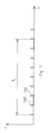
- Figure 1 schematically depicts the transmission T of several messages or signal packets 100 by a transmitter in a RF band having a transmission time limitation as a function of time t.
- the transmission time limitation can e.g. be expressed as a maximum transmission time (i.e. the accumulated time to transmit the signals 100) over a period TL.
- TL can e.g. be a period of 1 hour, during which hour the maximum transmission time is e.g. 1 %, or 36 sec.
- an average transmission delay can be determined from the transmission time limitation. In case signals of 4 ms are to be sent, the average transmission delay (i.e. the time between the transmission of two consecutive signals) should be 400 ms, in order to meet the transmission time limitation.
- a transmission with a shorter delay than the average transmission delay can be allowed when a time credit has been build up or when a negative time credit is build up.
- Such time credit can be build up during a period when the transmitter is not used or is used less than allowed, on average, by the transmission time limitation.
- a possible transmission schedule as can be realised with the present invention, is schematically shown in figure 2 .
- Figure 2 schematically depicts the transmission T of a plurality of signal packets 200 by an RF transmitter.
- Figure 2 also depicts the average transmission delay Ta as can be derived from the signal duration and the transmission time limitation (Ta e.g. being equal to 400 ms in case 4 ms signals are to be transmitted and an average transmission duty cycle of 1% being allowed).
- Ta e.g. being equal to 400 ms in case 4 ms signals are to be transmitted and an average transmission duty cycle of 1% being allowed.
- T1 e.g. being equal to 400 ms in case 4 ms signals are to be transmitted and an average transmission duty cycle of 1% being allowed.
- T1 e.g. being passed, during which, no transmission has occurred.
- a time credit has been build-up (e.g. in a linear manner). This can e.g. be realised in a processing unit of the user interface comprising the transmitter.
- the time credit is applied to allow signal packets being sent at a higher rate than allowed by the average transmission delay. This is done by determining a delay Td for the transmission of the signals based on the available time credit.
- a delay Td for the transmission of a signal can be set to Ta/2 as long as the available time credit is larger or equal to Ta/2.
- the delay Td can be set to a fixed value which is based on an average / normal response time of the user. Such a user response time can be determined based on experiments.
- a user response time can be predetermined and used as a fixed value for the delay, provided there is sufficient time credit.
- the delay Td can be set to 200 ms.
- Signal packets can be transmitter by the RF transmitter with a delay of 200 ms as long as a time credit larger than Ta-200 ms is available.
- the predetermined response time can be selected to correspond to a required response time corresponding to the delay between consecutive events, e.g. control signals from a separate control unit. In case such control unit may require the transmission of signal packets separated by a predetermined response time (this response time can e.g. be substantially smaller than normal user response time), such transmission can be possible when the required time credit is available.
- the transmission of two consecutive signals is to take place with a delay Td2 that can be longer than the average transmission delay, in order to comply with the transmission time limitation.
- Td2 a delay that can be longer than the average transmission delay
- the transmission delay as applied when no credit is available needs to be larger that the average transmission delay, in order not the exceed the average transmission delay Ta as allowed during the period TL.
- the required increase in transmission delay may easily be calculated from the time credit and the manner this time credit is applied to reduce the transmission delay.
- the time-credit should be limited.
- the time credit generation may e.g. be realised in a linear manner during a passed first period (e.g. 18 seconds) to a maximum time credit TCmax.
- the time credit may e.g. be reduced with a period equal to the average transmission delay for each signal packet transmitted.
- Figure 2 schematically depicts the build-up and reduction of the time credit corresponding to the transmission schedule of figure 2 (upper curve).
- a linear increase of the time credit has taken place when during the passed first period T1 no transmission was performed.
- the first period T1 need not be a fixed period in time but should preferable move along.
- the accumulated signal transmission time thus being determined over the latest first period that has passed.
- the transmission of a number of signal packets is required (e.g. by a user operating the user interface).
- the signal packets can be transmitted with a smaller than average transmission delay, as long as a sufficient amount of time credit is available (either positive or negative).
- the time credit is reduced (stepwise) with the appropriate amount (e.g. the average transmission delay minus the actual delay).
- the applied delay Td2 is determined to comply with the transmission time limitation. This may require a larger than average transmission delay, in order to meet the transmission time limitation.
- the accumulated transmission time over the passed period equal to TL can be used. From this accumulated transmission time and the maximum transmission time over a period TL, it can be determined whether or not a signal can be transmitted. When the application by the user of the user interface (i.e. the transmission of signals) is stopped prior to the time credit being equal to zero, the time credit can be increased again.
- the increase of the time credit can, as will be acknowledged by the skilled person, be implemented in various ways.
- the time credit can e.g. increase in a linear manner when no transmission is required.
- the time credit can be incremented with a certain value (e.g. the average transmission delay) each time a certain period (e.g. a fraction of the first period) has lapsed without a signal being transmitted.
- the time credit may also derived from a comparison of the actual transmission during the passed first period and the allowable transmission during such a first period assuming a uniform transmission schedule (as e.g. illustrated in figure 1 ).
- a time credit can be assigned based on the difference.
- the time credit may equally be implemented as a time debit (or negative time credit) allowing a user to transmit signal packets at a comparatively high duty cycle during a certain period, whereas the accumulated time debit needs to be compensated later on to comply with the transmission time limitation.
- the method according to the invention may advantageously be applied in a remote control user interface for a lighting system for controlling one or more light fixtures of the lighting system.
- Control of said light fixtures can e.g. include controlling the intensity of the light, or the colour.
- the lighting system may thus comprise a remote control user interface for providing control signals (as signal packets) to the light fixtures; the user interface thereto being equipped with an RF transmitter for transmitting the signal packets and the light fixtures being equipped with a receiver for receiving the signal packets.
- the remote control user interface may comprise a processing unit.
- the processing unit may further comprise a memory unit (preferably a non-volatile memory unit) for storing the time credit.
- the actual transmission pattern over the first period is stored in the memory unit. By doing so, the accumulated transmission during the first period may easily be monitored. It may be advantageous to keep the first period to a comparatively small value, e.g. 60 seconds or less, preferably 20 seconds. By doing so, the memory unit applied to store the actual transmission pattern can remain comparatively small.
- the processing unit may further be equipped with a timer or a counter for monitoring the actual transmission over the first period.
- the first period corresponds to the time that has lapsed since the last transmission. As soon as this period is larger than the average transmission delay, as can be determined from the transmission time limitation, the additional time can be stored as time credit. As soon as this credit is available, it can be applied to allow transmissions of signal packets with a delay that is smaller than the average transmission delay.
- the remote control user interface according to the invention can advantageously be applied in a lighting system according to the invention, the lighting system comprising a remote control user interface according to the invention and a light fixture comprising a receiver for receiving a control signal transmitted by the remote control user interface.
- the control signal can e.g. be transmitted by the remote control user interface in response to a user operation of the interface.
- the control signal can, as an example, comprise a set point or instruction for the light fixture (e.g. processed by control unit of the light fixture) to set or modify an illumination parameter (e.g. a colour or an intensity) of the light fixture.
- the light fixture comprises an LED unit comprising one or more LEDs, a power converter such as a switched mode power supply for providing power to the LED unit and a control unit arranged to receive the control signal from the receiver (e.g. via an input terminal), process the control signal and control the LED unit and/or the power converter in order to e.g. obtain the desired illumination parameter (e.g. by providing the processed control signal to the LED unit or power converter via an output terminal).
- the control unit is arranged to control the light fixture in accordance with the signal until a next signal is received.
- signals for controlling the LED units are often provided to the light fixtures in a substantially continuous manner.
- control unit of the light fixture as applied in an embodiment of the lighting system according to the invention does not require a continuous provision of a signal to control the light fixture. Instead, the control unit continues to apply the signal that was last received as an input to control the LED unit and/or power converter, until a next signal is received.
- a single processor, processing unit, control unit or other unit may fulfil the functions of several items recited in the claims.
Landscapes
- Engineering & Computer Science (AREA)
- Computer Networks & Wireless Communication (AREA)
- Physics & Mathematics (AREA)
- General Physics & Mathematics (AREA)
- Circuit Arrangement For Electric Light Sources In General (AREA)
Description
- The present invention relates to an RF transmitter for use in a lighting system for controlling one or more light fixtures of the light system.
- Present lighting systems, e.g. comprising a plurality of light fixtures such as halogen spots or LED (Light Emitting Diode) units may often be controlled by one or more user interfaces (e.g. remote control units) that apply RF transmission (either wireless or using Power Line Communication) for providing control signals to the light fixtures. A user interface (such as a remote control unit) of a lighting system is thus used to change / control an illumination parameter of the lighting system: It can e.g. be arranged to turn on/off one or more light fixtures, to dim the light of one or more of the light fixtures or to change the colour of one or more of the light fixtures of the system. The latter option can e.g. be found in light fixtures comprising LEDs of different colour and a control unit for adjusting the duty cycles of the LEDs of different colour thereby adjusting the output colour of the light fixture. In order to realise the required user settings of the lighting system, the user interface of such a lighting system may comprise an RF transmitter that transmits control signals comprising information on the required settings. The control signal (which is in general in the form of a signal packet) can e.g. be received by the light fixtures and processed in a control unit of the light fixtures such that the required user settings are realised. In order to obtain a certain level of user-friendliness, it is desirable that when a user interface is operated, the response (i.e. the adjustment of an illumination parameter) occurs as soon as possible, substantially without any delay noticeable to the user. In case a response to a control signal or signal packet would be delayed, the user may have the impression that the user interface did not acknowledge the input and operate the user interface again. As such, the user input may be processed twice resulting in an unwanted adjusted of the illumination parameter.
- When user interfaces having an RF transmitter are applied in a lighting system to control the light fixtures, the transmission of the RF signals may be limited due to regulations (see e.g. ETSI EN 300 220-1). In case such transmission of an RF signal in the RF band as applied is limited (e.g. to limited to a transmission during 1% of the time over a period of one hour), a series of user commands or inputs to the user interface may result in a noticeable delay between the input of the command and the actual execution of the command that e.g. results in the adjustment of the illumination parameter. Transmission time limitation in the RF band used may thus result in a delay which may confuse the user of the interface and incite the user to a further unnecessary application of the user interface.
- The patent document
US-A1-5 905 442 discloses a remote controller (20, 40) for an electrical device, e.g. a lighting device. The remote controller (20, 40) may transmit in a RF band having a transmission time limitation. One remote control may function as master (20), and others as slaves or repeaters (40). It is mentioned that if a repeater (40) has already communicated, it cannot retransmit again in its next slot if it would be within 100 milliseconds of its previous transmission. - In view of the above, it is desirable to improve the user-friendliness of user interfaces that apply RF transmission in an RF band having transmission time limitations.
- According to an aspect of the invention, there is provided a method of transmitting a signal packet by an RF transmitter of a remote control user interface in an RF band having a transmission time limitation, the method comprising:
- determining a time credit from an accumulated signal transmission time of the RF transmitter during a first period;
- determining a delay for the transmission of the signal packet to comply with the transmission time limitation using the time credit;
- transmit the signal packet taking the delay into account.
- By applying the method according the invention, the user-friendliness of e.g. a remote control user interface that applies RF in an RF band having a transmission time limitation can be improved. It is well known that certain RF bands e.g. 868 MHz may not be applied continuously but that a transmission in said RF band is limited. The transmission time limitation can e.g. be expressed as an allowable duty cycle of e.g. 1% measured over a period of one hour or as a maximum transmission time over a period of one hour, meaning that within any period of one hour, the total transmission time should not exceed the allowable duty cycle or maximum transmission time. It may further be advised that the total transmission time may not be applied in a single transmission but should be distributed over a plurality of transmissions. As an example, it can be recommended that the maximum on-time of a transmitter be limited to 3.6 sec whereas the allowable duty cycle over one hour is 1 %, i.e. 36 seconds. When the transmission of a message or signal packet (e.g. a control signal to a light fixture or a group of light fixtures) takes e.g. 4 ms, the next signal packet could, on average, only be transmitted 400 ms later (assuming a maximum duty cycle of 1% in the RF band applied) which is a comparatively long time. In case the user would need to transmit several signal packets (in order to make several adjustments to the system being controlled (e.g. a lighting system)), the user would thus experience that the user interface may respond rather slow to the commands. By applying the method according to the invention, a user interface (such as a remote control unit) is enabled to transmit messages (or commands) temporarily with a higher duty cycle than the average allowable duty-cycle of the RF band. In accordance with the invention, this is done by determining a time credit from an accumulated signal transmission time of the RF transmitter during a first period; The accumulated signal transmission time, in general, describing the actual transmission that was made during the first period. Such a time credit can e.g. be accumulated when the user interface is operated at a duty cycle that is lower than the allowable duty cycle. This time-credit can be applied to, temporarily, allow a higher duty cycle when required by the user. The time-credit can thus be spend when the user requires a higher duty cycle and can be accumulated again when the user interface is used at a lower than allowed duty cycle.
- This can be illustrated by the following example:
- Assuming an allowed duty cycle of 1% over one hour, the user thus being able to transmit during 36 s in one hour. When the interface is not used or user at a comparatively low duty cycle, a time credit can be accumulated. The time credit can e.g. be determined from the actual transmission over a certain period. By monitoring the actual transmission, a build-up, e.g. in a linear manner, of a time credit can be realised. When e.g. the remote control unit has not been used during a period of N1 seconds, a time credit of e.g. N2 seconds can be accumulated. As an example, when during a period of 20 seconds, the user interface has not been used, a time credit of 10 seconds can e.g. be build up. In principle, the rate at which the time credit is increased, can be selected. Allowing a large time credit and allowing the time credit to be spent may however affect the required delay when no credit is available. The time credit build-up may e.g. be based on the difference between the actual transmission delay and the average transmission delay as determined from the transmission time limitation of the RF band. Assuming that, during the period of N1 seconds, signal packets are transmitted with a delay of 500 ms and the average transmission delay to be 400 ms. In this situation, the time credit build-up can e.g. amount to 100 ms (500-400 ms) each 500 ms. If no transmissions are made during the N1 seconds, the build-up time credit would substantially correspond to N1. When, after said period of 20 seconds, the user starts using the interface intensively, the time-credit can be used to allow, at least partly, such intensive use. In accordance with the invention, this is done by determining a delay for the transmission of the signal to comply with the transmission time limitation using the time credit. Assuming a transmission time limitation of 1% for the RF band used and a signal duration of 4 ms, the delay between two consecutive transmission should, on average, be 400 ms. When the time credit is available, it can be used to determine a delay that is smaller. Instead of applying a delay of 400 ms between two consecutive transmissions, a delay of e.g. 100 ms could be applied when a sufficient time credit is available. When a delay of 100 ms is applied, i.e. the user interface is enabled to transmit control signals (having a length of 4 ms) every 100 ms, the time-credit could e.g. be reduced by 300 ms (400 ms - 100 ms) every 100 ms. The user would thus be allowed to operate at the increased duty cycle of 4% (4 ms transmission every 100 ms), until the time credit is reduced to zero. It can be noted that the delay, once determined may either be applied before the transmission of the signal or after the transmission or may even be subdivided in a part before and a part after the transmission. Once the time-credit is reduced to zero, the user interface can be disabled to operate at the increased duty cycle but only at a reduced duty cycle in order to comply with the transmission time limitation. In practice, the accumulation of time-credit as illustrated by the example is sufficient to significantly increase the user-friendliness of the interface as, in general, a user interface of e.g. a lighting system will only be applied occasionally to adjust an illumination parameter of a light fixture or a group of light fixtures. By accumulating the time-credit when the interface is not used, a substantially instantaneous response of the interface can be accomplished during a short period of time which, in general, will be sufficient to make the necessary parameter adjustments of the lighting system.
- By only allowing an increased response (i.e. a response at a higher duty-cycle than allowed continuously at the selected RF band) when time credit is available, the user in ensured that an, albeit limited, duty cycle will always be available. It should however be noted that the application of the time credit may also take the form of a time debit (or a negative time credit). Referring to the example above, an RF transmitter may be allowed to transmit signal packets with a higher duty cycle during a certain period of time, thereby accumulating a negative time credit. Based on this time credit, which may equally be determining from the accumulated signal transmission time of the RF transmitter during the first period, a delay can be determined to comply with the transmission time limitation. It can further be noted that the delay as determined (which substantially corresponds to the period between the transmission of a signal packet and the transmission of a previous or a next packet) can be applied either before the transmission of the packet or after. It can further be noted that the delay determined functions as a period during which no additional signal packets can be transmitted (in order to comply with the transmission time limitation).
- The method according to the invention may advantageously be applied in a remote control user interface for a lighting system. Such a remote control user interface comprising an RF transmitter for transmitting a signal packet for controlling the lighting system, the transmitter being arranged to transmit in an RF band having a transmission time limitation, the remote control user interface further comprising a processing unit arranged to
- determine a time credit from a transmission of the RF transmitter during a first period and to;
- determine a delay for the transmission of the signal packet to comply with the transmission time limitation using the time credit and
- control the RF transmitter to transmit the signal packet taking the delay into account.
- Determining the time credit and the delay for the transmission of the signal packet can be implemented in a processing unit such as a microcontroller or the like.
- Further aspects and embodiments of the invention are discussed in more detail in the description below.
-
-
Figure 1 schematically depicts a transmission schedule complying with a transmission time limitation by applying a fixed delay between transmissions. -
Figure 2 schematically depicts a transmission schedule as can be applied in an embodiment of the invention and a corresponding increase and decrease of time credit corresponding to the transmission schedule. -
Figure 1 schematically depicts the transmission T of several messages or signalpackets 100 by a transmitter in a RF band having a transmission time limitation as a function of time t. The transmission time limitation can e.g. be expressed as a maximum transmission time (i.e. the accumulated time to transmit the signals 100) over a period TL. TL can e.g. be a period of 1 hour, during which hour the maximum transmission time is e.g. 1 %, or 36 sec. When the transmission duration of a signal packet is known, an average transmission delay can be determined from the transmission time limitation. In case signals of 4 ms are to be sent, the average transmission delay (i.e. the time between the transmission of two consecutive signals) should be 400 ms, in order to meet the transmission time limitation. - In accordance with the invention, a transmission with a shorter delay than the average transmission delay can be allowed when a time credit has been build up or when a negative time credit is build up. Such time credit can be build up during a period when the transmitter is not used or is used less than allowed, on average, by the transmission time limitation. A possible transmission schedule as can be realised with the present invention, is schematically shown in
figure 2 . -
Figure 2 (upper curve) schematically depicts the transmission T of a plurality ofsignal packets 200 by an RF transmitter.Figure 2 (upper curve) also depicts the average transmission delay Ta as can be derived from the signal duration and the transmission time limitation (Ta e.g. being equal to 400 ms in case 4 ms signals are to be transmitted and an average transmission duty cycle of 1% being allowed). Further indication infigure 2 is a first period T1, in the example shown, said period being passed, during which, no transmission has occurred. During said period, e.g. 18 seconds a time credit has been build-up (e.g. in a linear manner). This can e.g. be realised in a processing unit of the user interface comprising the transmitter. When a non-zero time credit is thus available when a user operates the user interface with the transmitter, the time credit is applied to allow signal packets being sent at a higher rate than allowed by the average transmission delay. This is done by determining a delay Td for the transmission of the signals based on the available time credit. As an example, a delay Td for the transmission of a signal can be set to Ta/2 as long as the available time credit is larger or equal to Ta/2. Each time a signal packet is thus transmitted, the time credit is reduced with Ta/2. As an alternative, the delay Td can be set to a fixed value which is based on an average / normal response time of the user. Such a user response time can be determined based on experiments. As such a user response time can be predetermined and used as a fixed value for the delay, provided there is sufficient time credit. As an example, the delay Td can be set to 200 ms. Signal packets can be transmitter by the RF transmitter with a delay of 200 ms as long as a time credit larger than Ta-200 ms is available. As an alternative, the predetermined response time can be selected to correspond to a required response time corresponding to the delay between consecutive events, e.g. control signals from a separate control unit. In case such control unit may require the transmission of signal packets separated by a predetermined response time (this response time can e.g. be substantially smaller than normal user response time), such transmission can be possible when the required time credit is available. - In case the time credit is zero and the user would still require the transmission of a signal packets, the transmission of two consecutive signals is to take place with a delay Td2 that can be longer than the average transmission delay, in order to comply with the transmission time limitation. This can be understood as follows: When the transmission time limitation is expressed as a maximum total transmission time during a period TL (e.g. one hour), this period TL may have arbitrary starting point. When the starting point of the period TL is set to correspond to the starting point of the transmission at a shorter than average transmission delay, it will be clear to the skilled person that, in order to comply with the transmission time limitation, the transmission delay as applied when no credit is available, needs to be larger that the average transmission delay, in order not the exceed the average transmission delay Ta as allowed during the period TL. The required increase in transmission delay may easily be calculated from the time credit and the manner this time credit is applied to reduce the transmission delay. In order not the obtain an excessive increase in transmission delay, the time-credit should be limited. The time credit generation may e.g. be realised in a linear manner during a passed first period (e.g. 18 seconds) to a maximum time credit TCmax. In case one or more transmissions of a signal packets have taken place during the first period, the time credit may e.g. be reduced with a period equal to the average transmission delay for each signal packet transmitted.
-
Figure 2 (lower curve) schematically depicts the build-up and reduction of the time credit corresponding to the transmission schedule offigure 2 (upper curve). As can be seen, a linear increase of the time credit has taken place when during the passed first period T1 no transmission was performed. The first period T1 need not be a fixed period in time but should preferable move along. The accumulated signal transmission time thus being determined over the latest first period that has passed. Starting from t = 0, the transmission of a number of signal packets is required (e.g. by a user operating the user interface). As explained above, the signal packets can be transmitted with a smaller than average transmission delay, as long as a sufficient amount of time credit is available (either positive or negative). Once a signal packet is transmitted with a smaller than average transmission delay, the time credit is reduced (stepwise) with the appropriate amount (e.g. the average transmission delay minus the actual delay). In the example as shown, once the time credit is equal to zero, the applied delay Td2 is determined to comply with the transmission time limitation. This may require a larger than average transmission delay, in order to meet the transmission time limitation. In order to determine the required delay in such case (i.e. when the time credit is equal to zero), the accumulated transmission time over the passed period equal to TL can be used. From this accumulated transmission time and the maximum transmission time over a period TL, it can be determined whether or not a signal can be transmitted. When the application by the user of the user interface (i.e. the transmission of signals) is stopped prior to the time credit being equal to zero, the time credit can be increased again. - The increase of the time credit can, as will be acknowledged by the skilled person, be implemented in various ways. The time credit can e.g. increase in a linear manner when no transmission is required. As an alternative, the time credit can be incremented with a certain value (e.g. the average transmission delay) each time a certain period (e.g. a fraction of the first period) has lapsed without a signal being transmitted. The time credit may also derived from a comparison of the actual transmission during the passed first period and the allowable transmission during such a first period assuming a uniform transmission schedule (as e.g. illustrated in
figure 1 ). When the actual transmission during the passed first period is smaller than would be allowed when an average transmission delay Ta (seefigure 2 ) is applied, a time credit can be assigned based on the difference. As explained above, the time credit may equally be implemented as a time debit (or negative time credit) allowing a user to transmit signal packets at a comparatively high duty cycle during a certain period, whereas the accumulated time debit needs to be compensated later on to comply with the transmission time limitation. - The method according to the invention may advantageously be applied in a remote control user interface for a lighting system for controlling one or more light fixtures of the lighting system. Control of said light fixtures can e.g. include controlling the intensity of the light, or the colour. The lighting system may thus comprise a remote control user interface for providing control signals (as signal packets) to the light fixtures; the user interface thereto being equipped with an RF transmitter for transmitting the signal packets and the light fixtures being equipped with a receiver for receiving the signal packets. In order to determine the required delay for transmitting a control signal (in general, a signal), the remote control user interface may comprise a processing unit. The processing unit may further comprise a memory unit (preferably a non-volatile memory unit) for storing the time credit. In an embodiment, the actual transmission pattern over the first period is stored in the memory unit. By doing so, the accumulated transmission during the first period may easily be monitored. It may be advantageous to keep the first period to a comparatively small value, e.g. 60 seconds or less, preferably 20 seconds. By doing so, the memory unit applied to store the actual transmission pattern can remain comparatively small. The processing unit may further be equipped with a timer or a counter for monitoring the actual transmission over the first period. In an embodiment of the present invention, the first period corresponds to the time that has lapsed since the last transmission. As soon as this period is larger than the average transmission delay, as can be determined from the transmission time limitation, the additional time can be stored as time credit. As soon as this credit is available, it can be applied to allow transmissions of signal packets with a delay that is smaller than the average transmission delay.
- The remote control user interface according to the invention can advantageously be applied in a lighting system according to the invention, the lighting system comprising a remote control user interface according to the invention and a light fixture comprising a receiver for receiving a control signal transmitted by the remote control user interface. The control signal can e.g. be transmitted by the remote control user interface in response to a user operation of the interface. The control signal can, as an example, comprise a set point or instruction for the light fixture (e.g. processed by control unit of the light fixture) to set or modify an illumination parameter (e.g. a colour or an intensity) of the light fixture. In an embodiment, the light fixture comprises an LED unit comprising one or more LEDs, a power converter such as a switched mode power supply for providing power to the LED unit and a control unit arranged to receive the control signal from the receiver (e.g. via an input terminal), process the control signal and control the LED unit and/or the power converter in order to e.g. obtain the desired illumination parameter (e.g. by providing the processed control signal to the LED unit or power converter via an output terminal). In an embodiment, the control unit is arranged to control the light fixture in accordance with the signal until a next signal is received. In conventional LED based lighting applications or systems, signals for controlling the LED units are often provided to the light fixtures in a substantially continuous manner. In order to avoid such continuous provision of control signals, the control unit of the light fixture as applied in an embodiment of the lighting system according to the invention does not require a continuous provision of a signal to control the light fixture. Instead, the control unit continues to apply the signal that was last received as an input to control the LED unit and/or power converter, until a next signal is received.
- As required, detailed embodiments of the present invention are disclosed herein; however, it is to be understood that the disclosed embodiments are merely exemplary of the invention, which can be embodied in various forms. Therefore, specific structural and functional details disclosed herein are not to be interpreted as limiting, but merely as a basis for the claims and as a representative basis for teaching one skilled in the art to variously employ the present invention in virtually any appropriately detailed structure. Further, the terms and phrases used herein are not intended to be limiting, but rather, to provide an understandable description of the invention.
- The terms "a" or "an", as used herein, are defined as one or more than one. The term plurality, as used herein, is defined as two or more than two. The term another, as used herein, is defined as at least a second or more. The terms including and/or having, as used herein, are defined as comprising (i.e., open language, not excluding other elements or steps). Any reference signs in the claims should not be construed as limiting the scope of the claims or the invention.
- The mere fact that certain measures are recited in mutually different dependent claims does not indicate that a combination of these measures cannot be used to advantage.
- The term coupled, as used herein, is defined as connected, although not necessarily directly, and not necessarily mechanically.
- A single processor, processing unit, control unit or other unit may fulfil the functions of several items recited in the claims.
Claims (15)
- Method of transmitting a signal packet (100, 200) by an RF transmitter of a remote control user interface in an RF band having a transmission time limitation, the method being characterised by:- determining a time credit from an accumulated signal transmission time of the RF transmitter during a first period (T1);- determining a delay (Td) for the transmission of the signal packet (100, 200) to comply with the transmission time limitation using the time credit;- transmit the signal packet (100, 200) taking the delay (Td) into account.
- The method according to claim 1 wherein the delay (Td) is determined from an average transmission delay (Ta) in the RF band and the time credit.
- The method according to claim 2 wherein the delay substantially corresponds to a predetermined response time when the time credit is larger than the average transmission delay (Ta) minus the predetermined user response time.
- The method according to claim 1 or 2 wherein the transmission time limitation comprises a maximum transmission time during a second period.
- The method according to any preceding claim wherein the time credit is determined from an accumulated transmission during the first period (T1).
- The method according to claim 2 wherein the delay (Td) is larger than the average transmission delay (Ta) when the time credit is equal to zero.
- The method according to any preceding claim wherein the time credit is limited to a maximum time credit.
- The method according to any preceding claim wherein the first period (T1) is less than 60 seconds.
- The method according to claim 4 wherein the delay (Td) is determined from an accumulated transmission time (Ta) during the passed second period when the time credit is equal to zero.
- Remote control user interface for a lighting system, the user interface comprising an RF transmitter for transmitting a signal packet (100, 200) for controlling the lighting system, the transmitter being arranged to transmit in an RF band having a transmission time limitation, characterised in that the user interface comprises a processing unit arranged to- determine a time credit from a transmission of the RF transmitter during a passed first period (T1);- determine a delay (Td) for the transmission of the signal packet (100, 200) to comply with the transmission limitation using the time credit and;- control the RF transmitter to transmit the signal packet (100, 200) taking the delay (Td) into account.
- The remote control user interface according to claim 10 wherein the delay (Td) is determined from an average transmission delay (Ta) in the RF band and the time credit.
- The remote control user interface according to claim 10 wherein the delay (Td) substantially corresponds to a predetermined user response time when the time credit is larger than the average transmission delay (Ta) minus the predetermined user response time.
- A lighting system comprising a remote control user interface according to any of the claims 10 to 12 and a light fixture arranged to receive the signal (100, 200) from the remote control user interface.
- The lighting system according to claim 13 wherein the light fixture comprises:- a receiver for receiving the signal (100, 200);- an LED unit comprising one or more LEDs;- a power converter for powering the LED unit;- a control unit comprising an input terminal for receiving the signal (100, 200) from the receiver, the control unit being arranged to process the signal to a control signal and provide the control signal, via an output terminal to the LED unit and/or the power converter for controlling the light fixture in accordance with the signal.
- The lighting system according to claim 14 wherein the control unit is arranged to control the light fixture in accordance with the signal (100, 200) until a next signal is received from the remote control user interface.
Applications Claiming Priority (2)
| Application Number | Priority Date | Filing Date | Title |
|---|---|---|---|
| US9310208P | 2008-08-29 | 2008-08-29 | |
| PCT/NL2009/000166 WO2010024665A1 (en) | 2008-08-29 | 2009-08-27 | Method of transmitting a signal packet by an rf transmitter of a remote control user interface and a remote control unit for a lighting system comprising an rf transmitter |
Publications (2)
| Publication Number | Publication Date |
|---|---|
| EP2332395A1 EP2332395A1 (en) | 2011-06-15 |
| EP2332395B1 true EP2332395B1 (en) | 2014-06-25 |
Family
ID=41168540
Family Applications (1)
| Application Number | Title | Priority Date | Filing Date |
|---|---|---|---|
| EP09788152.8A Active EP2332395B1 (en) | 2008-08-29 | 2009-08-27 | Method of transmitting a signal packet by an rf transmitter of a remote control user interface and a remote control unit for a lighting system comprising an rf transmitter |
Country Status (2)
| Country | Link |
|---|---|
| EP (1) | EP2332395B1 (en) |
| WO (1) | WO2010024665A1 (en) |
Families Citing this family (1)
| Publication number | Priority date | Publication date | Assignee | Title |
|---|---|---|---|---|
| EP2842399B1 (en) * | 2012-04-27 | 2017-03-15 | Philips Lighting Holding B.V. | Duty-cycle control in wireless network |
Family Cites Families (3)
| Publication number | Priority date | Publication date | Assignee | Title |
|---|---|---|---|---|
| US5905442A (en) * | 1996-02-07 | 1999-05-18 | Lutron Electronics Co., Inc. | Method and apparatus for controlling and determining the status of electrical devices from remote locations |
| US7536194B2 (en) * | 2005-09-30 | 2009-05-19 | Robert Bosch Gmbh | Method and system for providing an energy efficient exchange of information in wireless networks |
| US7573208B2 (en) * | 2007-03-05 | 2009-08-11 | Lutron Electronics Co., Inc. | Method of programming a lighting preset from a radio-frequency remote control |
-
2009
- 2009-08-27 WO PCT/NL2009/000166 patent/WO2010024665A1/en active Application Filing
- 2009-08-27 EP EP09788152.8A patent/EP2332395B1/en active Active
Also Published As
| Publication number | Publication date |
|---|---|
| EP2332395A1 (en) | 2011-06-15 |
| WO2010024665A1 (en) | 2010-03-04 |
Similar Documents
| Publication | Publication Date | Title |
|---|---|---|
| JP5893409B2 (en) | Method for controlling a lighting system | |
| JP5814398B2 (en) | Method and apparatus for operating high power LED group | |
| EP2329687B1 (en) | Configurable light fixture, configurable lighting system and method for configuring a lighting system | |
| US20090206983A1 (en) | Communication System for a Radio-Frequency Load Control System | |
| AU2005316790A1 (en) | Distributed intelligence ballast system and extended lighting control protocol | |
| EP2584875A1 (en) | Lamps and illuminating system | |
| JP5615916B2 (en) | Push bit for semi-synchronized pointing | |
| JP6508597B2 (en) | Lighting controller and control method of lighting device | |
| KR20120047913A (en) | Improved detection using transmission notification | |
| EP2332395B1 (en) | Method of transmitting a signal packet by an rf transmitter of a remote control user interface and a remote control unit for a lighting system comprising an rf transmitter | |
| EP2910089B1 (en) | Apparatus and method for interpreting received control commands | |
| JP2018110089A (en) | Illumination control system, illumination control method, controller, and control method | |
| US20170055332A1 (en) | Illumination system | |
| KR101700441B1 (en) | Remote control of a plurality of devices | |
| EP3574714B1 (en) | A lighting device arranged to be controlled via a wireless controller | |
| JP5186261B2 (en) | Wireless dimming control system | |
| US11564304B2 (en) | Dimmer system control | |
| JP2000196526A (en) | Infrared transmitter | |
| US9814119B2 (en) | Method and system for actuating loads connected to a bus system | |
| US20200351995A1 (en) | Dimmer system control | |
| JP6985093B2 (en) | Lamp control device | |
| JP2019515418A (en) | Operating circuit and method for operating at least one light emitter | |
| JP4940100B2 (en) | Remote control lighting system | |
| CN109792825B (en) | Battery-powered lighting control assembly, lighting system and method of commissioning a lighting system | |
| JP2023156093A (en) | lighting system |
Legal Events
| Date | Code | Title | Description |
|---|---|---|---|
| PUAI | Public reference made under article 153(3) epc to a published international application that has entered the european phase |
Free format text: ORIGINAL CODE: 0009012 |
|
| 17P | Request for examination filed |
Effective date: 20110324 |
|
| AK | Designated contracting states |
Kind code of ref document: A1 Designated state(s): AT BE BG CH CY CZ DE DK EE ES FI FR GB GR HR HU IE IS IT LI LT LU LV MC MK MT NL NO PL PT RO SE SI SK SM TR |
|
| AX | Request for extension of the european patent |
Extension state: AL BA RS |
|
| DAX | Request for extension of the european patent (deleted) | ||
| GRAP | Despatch of communication of intention to grant a patent |
Free format text: ORIGINAL CODE: EPIDOSNIGR1 |
|
| INTG | Intention to grant announced |
Effective date: 20140228 |
|
| GRAS | Grant fee paid |
Free format text: ORIGINAL CODE: EPIDOSNIGR3 |
|
| GRAA | (expected) grant |
Free format text: ORIGINAL CODE: 0009210 |
|
| AK | Designated contracting states |
Kind code of ref document: B1 Designated state(s): AT BE BG CH CY CZ DE DK EE ES FI FR GB GR HR HU IE IS IT LI LT LU LV MC MK MT NL NO PL PT RO SE SI SK SM TR |
|
| REG | Reference to a national code |
Ref country code: GB Ref legal event code: FG4D |
|
| REG | Reference to a national code |
Ref country code: CH Ref legal event code: EP |
|
| REG | Reference to a national code |
Ref country code: AT Ref legal event code: REF Ref document number: 675352 Country of ref document: AT Kind code of ref document: T Effective date: 20140715 |
|
| REG | Reference to a national code |
Ref country code: IE Ref legal event code: FG4D |
|
| REG | Reference to a national code |
Ref country code: DE Ref legal event code: R096 Ref document number: 602009024959 Country of ref document: DE Effective date: 20140807 |
|
| REG | Reference to a national code |
Ref country code: NL Ref legal event code: T3 |
|
| PG25 | Lapsed in a contracting state [announced via postgrant information from national office to epo] |
Ref country code: LT Free format text: LAPSE BECAUSE OF FAILURE TO SUBMIT A TRANSLATION OF THE DESCRIPTION OR TO PAY THE FEE WITHIN THE PRESCRIBED TIME-LIMIT Effective date: 20140625 Ref country code: FI Free format text: LAPSE BECAUSE OF FAILURE TO SUBMIT A TRANSLATION OF THE DESCRIPTION OR TO PAY THE FEE WITHIN THE PRESCRIBED TIME-LIMIT Effective date: 20140625 Ref country code: NO Free format text: LAPSE BECAUSE OF FAILURE TO SUBMIT A TRANSLATION OF THE DESCRIPTION OR TO PAY THE FEE WITHIN THE PRESCRIBED TIME-LIMIT Effective date: 20140925 Ref country code: CY Free format text: LAPSE BECAUSE OF FAILURE TO SUBMIT A TRANSLATION OF THE DESCRIPTION OR TO PAY THE FEE WITHIN THE PRESCRIBED TIME-LIMIT Effective date: 20140625 Ref country code: GR Free format text: LAPSE BECAUSE OF FAILURE TO SUBMIT A TRANSLATION OF THE DESCRIPTION OR TO PAY THE FEE WITHIN THE PRESCRIBED TIME-LIMIT Effective date: 20140926 |
|
| REG | Reference to a national code |
Ref country code: AT Ref legal event code: MK05 Ref document number: 675352 Country of ref document: AT Kind code of ref document: T Effective date: 20140625 |
|
| REG | Reference to a national code |
Ref country code: LT Ref legal event code: MG4D |
|
| PG25 | Lapsed in a contracting state [announced via postgrant information from national office to epo] |
Ref country code: LV Free format text: LAPSE BECAUSE OF FAILURE TO SUBMIT A TRANSLATION OF THE DESCRIPTION OR TO PAY THE FEE WITHIN THE PRESCRIBED TIME-LIMIT Effective date: 20140625 Ref country code: SE Free format text: LAPSE BECAUSE OF FAILURE TO SUBMIT A TRANSLATION OF THE DESCRIPTION OR TO PAY THE FEE WITHIN THE PRESCRIBED TIME-LIMIT Effective date: 20140625 Ref country code: HR Free format text: LAPSE BECAUSE OF FAILURE TO SUBMIT A TRANSLATION OF THE DESCRIPTION OR TO PAY THE FEE WITHIN THE PRESCRIBED TIME-LIMIT Effective date: 20140625 |
|
| PG25 | Lapsed in a contracting state [announced via postgrant information from national office to epo] |
Ref country code: CZ Free format text: LAPSE BECAUSE OF FAILURE TO SUBMIT A TRANSLATION OF THE DESCRIPTION OR TO PAY THE FEE WITHIN THE PRESCRIBED TIME-LIMIT Effective date: 20140625 Ref country code: EE Free format text: LAPSE BECAUSE OF FAILURE TO SUBMIT A TRANSLATION OF THE DESCRIPTION OR TO PAY THE FEE WITHIN THE PRESCRIBED TIME-LIMIT Effective date: 20140625 Ref country code: SK Free format text: LAPSE BECAUSE OF FAILURE TO SUBMIT A TRANSLATION OF THE DESCRIPTION OR TO PAY THE FEE WITHIN THE PRESCRIBED TIME-LIMIT Effective date: 20140625 Ref country code: PT Free format text: LAPSE BECAUSE OF FAILURE TO SUBMIT A TRANSLATION OF THE DESCRIPTION OR TO PAY THE FEE WITHIN THE PRESCRIBED TIME-LIMIT Effective date: 20141027 Ref country code: RO Free format text: LAPSE BECAUSE OF FAILURE TO SUBMIT A TRANSLATION OF THE DESCRIPTION OR TO PAY THE FEE WITHIN THE PRESCRIBED TIME-LIMIT Effective date: 20140625 Ref country code: ES Free format text: LAPSE BECAUSE OF FAILURE TO SUBMIT A TRANSLATION OF THE DESCRIPTION OR TO PAY THE FEE WITHIN THE PRESCRIBED TIME-LIMIT Effective date: 20140625 |
|
| PG25 | Lapsed in a contracting state [announced via postgrant information from national office to epo] |
Ref country code: PL Free format text: LAPSE BECAUSE OF FAILURE TO SUBMIT A TRANSLATION OF THE DESCRIPTION OR TO PAY THE FEE WITHIN THE PRESCRIBED TIME-LIMIT Effective date: 20140625 Ref country code: AT Free format text: LAPSE BECAUSE OF FAILURE TO SUBMIT A TRANSLATION OF THE DESCRIPTION OR TO PAY THE FEE WITHIN THE PRESCRIBED TIME-LIMIT Effective date: 20140625 Ref country code: IS Free format text: LAPSE BECAUSE OF FAILURE TO SUBMIT A TRANSLATION OF THE DESCRIPTION OR TO PAY THE FEE WITHIN THE PRESCRIBED TIME-LIMIT Effective date: 20141025 |
|
| REG | Reference to a national code |
Ref country code: DE Ref legal event code: R097 Ref document number: 602009024959 Country of ref document: DE |
|
| PG25 | Lapsed in a contracting state [announced via postgrant information from national office to epo] |
Ref country code: LU Free format text: LAPSE BECAUSE OF FAILURE TO SUBMIT A TRANSLATION OF THE DESCRIPTION OR TO PAY THE FEE WITHIN THE PRESCRIBED TIME-LIMIT Effective date: 20140827 Ref country code: MC Free format text: LAPSE BECAUSE OF FAILURE TO SUBMIT A TRANSLATION OF THE DESCRIPTION OR TO PAY THE FEE WITHIN THE PRESCRIBED TIME-LIMIT Effective date: 20140625 |
|
| REG | Reference to a national code |
Ref country code: CH Ref legal event code: PL |
|
| PG25 | Lapsed in a contracting state [announced via postgrant information from national office to epo] |
Ref country code: LI Free format text: LAPSE BECAUSE OF NON-PAYMENT OF DUE FEES Effective date: 20140831 Ref country code: BE Free format text: LAPSE BECAUSE OF NON-PAYMENT OF DUE FEES Effective date: 20140831 Ref country code: DK Free format text: LAPSE BECAUSE OF FAILURE TO SUBMIT A TRANSLATION OF THE DESCRIPTION OR TO PAY THE FEE WITHIN THE PRESCRIBED TIME-LIMIT Effective date: 20140625 Ref country code: CH Free format text: LAPSE BECAUSE OF NON-PAYMENT OF DUE FEES Effective date: 20140831 Ref country code: IT Free format text: LAPSE BECAUSE OF FAILURE TO SUBMIT A TRANSLATION OF THE DESCRIPTION OR TO PAY THE FEE WITHIN THE PRESCRIBED TIME-LIMIT Effective date: 20140625 |
|
| PLBE | No opposition filed within time limit |
Free format text: ORIGINAL CODE: 0009261 |
|
| STAA | Information on the status of an ep patent application or granted ep patent |
Free format text: STATUS: NO OPPOSITION FILED WITHIN TIME LIMIT |
|
| REG | Reference to a national code |
Ref country code: IE Ref legal event code: MM4A |
|
| 26N | No opposition filed |
Effective date: 20150326 |
|
| PG25 | Lapsed in a contracting state [announced via postgrant information from national office to epo] |
Ref country code: BE Free format text: LAPSE BECAUSE OF FAILURE TO SUBMIT A TRANSLATION OF THE DESCRIPTION OR TO PAY THE FEE WITHIN THE PRESCRIBED TIME-LIMIT Effective date: 20140625 |
|
| PG25 | Lapsed in a contracting state [announced via postgrant information from national office to epo] |
Ref country code: IE Free format text: LAPSE BECAUSE OF NON-PAYMENT OF DUE FEES Effective date: 20140827 |
|
| PG25 | Lapsed in a contracting state [announced via postgrant information from national office to epo] |
Ref country code: SI Free format text: LAPSE BECAUSE OF FAILURE TO SUBMIT A TRANSLATION OF THE DESCRIPTION OR TO PAY THE FEE WITHIN THE PRESCRIBED TIME-LIMIT Effective date: 20140625 |
|
| PG25 | Lapsed in a contracting state [announced via postgrant information from national office to epo] |
Ref country code: SM Free format text: LAPSE BECAUSE OF FAILURE TO SUBMIT A TRANSLATION OF THE DESCRIPTION OR TO PAY THE FEE WITHIN THE PRESCRIBED TIME-LIMIT Effective date: 20140625 |
|
| PG25 | Lapsed in a contracting state [announced via postgrant information from national office to epo] |
Ref country code: MT Free format text: LAPSE BECAUSE OF FAILURE TO SUBMIT A TRANSLATION OF THE DESCRIPTION OR TO PAY THE FEE WITHIN THE PRESCRIBED TIME-LIMIT Effective date: 20140625 Ref country code: BG Free format text: LAPSE BECAUSE OF FAILURE TO SUBMIT A TRANSLATION OF THE DESCRIPTION OR TO PAY THE FEE WITHIN THE PRESCRIBED TIME-LIMIT Effective date: 20140625 |
|
| PG25 | Lapsed in a contracting state [announced via postgrant information from national office to epo] |
Ref country code: TR Free format text: LAPSE BECAUSE OF FAILURE TO SUBMIT A TRANSLATION OF THE DESCRIPTION OR TO PAY THE FEE WITHIN THE PRESCRIBED TIME-LIMIT Effective date: 20140625 Ref country code: HU Free format text: LAPSE BECAUSE OF FAILURE TO SUBMIT A TRANSLATION OF THE DESCRIPTION OR TO PAY THE FEE WITHIN THE PRESCRIBED TIME-LIMIT; INVALID AB INITIO Effective date: 20090827 |
|
| REG | Reference to a national code |
Ref country code: FR Ref legal event code: PLFP Year of fee payment: 8 |
|
| REG | Reference to a national code |
Ref country code: FR Ref legal event code: PLFP Year of fee payment: 9 |
|
| PG25 | Lapsed in a contracting state [announced via postgrant information from national office to epo] |
Ref country code: MK Free format text: LAPSE BECAUSE OF FAILURE TO SUBMIT A TRANSLATION OF THE DESCRIPTION OR TO PAY THE FEE WITHIN THE PRESCRIBED TIME-LIMIT Effective date: 20140625 |
|
| REG | Reference to a national code |
Ref country code: FR Ref legal event code: PLFP Year of fee payment: 10 |
|
| PGFP | Annual fee paid to national office [announced via postgrant information from national office to epo] |
Ref country code: NL Payment date: 20230825 Year of fee payment: 15 |
|
| PGFP | Annual fee paid to national office [announced via postgrant information from national office to epo] |
Ref country code: GB Payment date: 20230824 Year of fee payment: 15 |
|
| PGFP | Annual fee paid to national office [announced via postgrant information from national office to epo] |
Ref country code: FR Payment date: 20230822 Year of fee payment: 15 Ref country code: DE Payment date: 20230822 Year of fee payment: 15 |