EP2325593B1 - Heat exchanger - Google Patents
Heat exchanger Download PDFInfo
- Publication number
- EP2325593B1 EP2325593B1 EP09290872.2A EP09290872A EP2325593B1 EP 2325593 B1 EP2325593 B1 EP 2325593B1 EP 09290872 A EP09290872 A EP 09290872A EP 2325593 B1 EP2325593 B1 EP 2325593B1
- Authority
- EP
- European Patent Office
- Prior art keywords
- opening
- connection
- fluid
- heat exchanger
- arrangement
- Prior art date
- Legal status (The legal status is an assumption and is not a legal conclusion. Google has not performed a legal analysis and makes no representation as to the accuracy of the status listed.)
- Active
Links
- 239000012530 fluid Substances 0.000 claims description 43
- 238000004519 manufacturing process Methods 0.000 claims description 23
- 239000003507 refrigerant Substances 0.000 claims description 18
- 238000005476 soldering Methods 0.000 claims description 14
- 238000004378 air conditioning Methods 0.000 claims description 9
- 238000000034 method Methods 0.000 claims description 8
- 238000004080 punching Methods 0.000 claims description 6
- 238000001816 cooling Methods 0.000 claims description 5
- 238000010438 heat treatment Methods 0.000 claims description 4
- 238000007599 discharging Methods 0.000 claims description 2
- 238000000465 moulding Methods 0.000 claims 5
- 238000000748 compression moulding Methods 0.000 claims 1
- 238000001125 extrusion Methods 0.000 description 14
- 239000000463 material Substances 0.000 description 13
- 229910052782 aluminium Inorganic materials 0.000 description 7
- XAGFODPZIPBFFR-UHFFFAOYSA-N aluminium Chemical compound [Al] XAGFODPZIPBFFR-UHFFFAOYSA-N 0.000 description 7
- 238000005553 drilling Methods 0.000 description 5
- XEEYBQQBJWHFJM-UHFFFAOYSA-N Iron Chemical compound [Fe] XEEYBQQBJWHFJM-UHFFFAOYSA-N 0.000 description 4
- 238000005219 brazing Methods 0.000 description 4
- 238000003801 milling Methods 0.000 description 4
- 238000005260 corrosion Methods 0.000 description 3
- 230000007797 corrosion Effects 0.000 description 3
- 229910052751 metal Inorganic materials 0.000 description 3
- 239000002184 metal Substances 0.000 description 3
- 239000007787 solid Substances 0.000 description 3
- 230000015572 biosynthetic process Effects 0.000 description 2
- 239000011248 coating agent Substances 0.000 description 2
- 238000000576 coating method Methods 0.000 description 2
- 238000013461 design Methods 0.000 description 2
- 229910052742 iron Inorganic materials 0.000 description 2
- 238000003754 machining Methods 0.000 description 2
- 229910000831 Steel Inorganic materials 0.000 description 1
- 238000004891 communication Methods 0.000 description 1
- 238000005520 cutting process Methods 0.000 description 1
- 239000013529 heat transfer fluid Substances 0.000 description 1
- 239000007788 liquid Substances 0.000 description 1
- 238000007747 plating Methods 0.000 description 1
- 238000005096 rolling process Methods 0.000 description 1
- 229910000679 solder Inorganic materials 0.000 description 1
- 229910001220 stainless steel Inorganic materials 0.000 description 1
- 239000010935 stainless steel Substances 0.000 description 1
- 239000010959 steel Substances 0.000 description 1
- 238000012549 training Methods 0.000 description 1
- 238000012546 transfer Methods 0.000 description 1
- XLYOFNOQVPJJNP-UHFFFAOYSA-N water Substances O XLYOFNOQVPJJNP-UHFFFAOYSA-N 0.000 description 1
Images
Classifications
-
- F—MECHANICAL ENGINEERING; LIGHTING; HEATING; WEAPONS; BLASTING
- F28—HEAT EXCHANGE IN GENERAL
- F28F—DETAILS OF HEAT-EXCHANGE AND HEAT-TRANSFER APPARATUS, OF GENERAL APPLICATION
- F28F9/00—Casings; Header boxes; Auxiliary supports for elements; Auxiliary members within casings
- F28F9/02—Header boxes; End plates
- F28F9/0246—Arrangements for connecting header boxes with flow lines
- F28F9/0248—Arrangements for sealing connectors to header boxes
-
- F—MECHANICAL ENGINEERING; LIGHTING; HEATING; WEAPONS; BLASTING
- F28—HEAT EXCHANGE IN GENERAL
- F28D—HEAT-EXCHANGE APPARATUS, NOT PROVIDED FOR IN ANOTHER SUBCLASS, IN WHICH THE HEAT-EXCHANGE MEDIA DO NOT COME INTO DIRECT CONTACT
- F28D1/00—Heat-exchange apparatus having stationary conduit assemblies for one heat-exchange medium only, the media being in contact with different sides of the conduit wall, in which the other heat-exchange medium is a large body of fluid, e.g. domestic or motor car radiators
- F28D1/02—Heat-exchange apparatus having stationary conduit assemblies for one heat-exchange medium only, the media being in contact with different sides of the conduit wall, in which the other heat-exchange medium is a large body of fluid, e.g. domestic or motor car radiators with heat-exchange conduits immersed in the body of fluid
- F28D1/04—Heat-exchange apparatus having stationary conduit assemblies for one heat-exchange medium only, the media being in contact with different sides of the conduit wall, in which the other heat-exchange medium is a large body of fluid, e.g. domestic or motor car radiators with heat-exchange conduits immersed in the body of fluid with tubular conduits
- F28D1/053—Heat-exchange apparatus having stationary conduit assemblies for one heat-exchange medium only, the media being in contact with different sides of the conduit wall, in which the other heat-exchange medium is a large body of fluid, e.g. domestic or motor car radiators with heat-exchange conduits immersed in the body of fluid with tubular conduits the conduits being straight
- F28D1/0535—Heat-exchange apparatus having stationary conduit assemblies for one heat-exchange medium only, the media being in contact with different sides of the conduit wall, in which the other heat-exchange medium is a large body of fluid, e.g. domestic or motor car radiators with heat-exchange conduits immersed in the body of fluid with tubular conduits the conduits being straight the conduits having a non-circular cross-section
- F28D1/05366—Assemblies of conduits connected to common headers, e.g. core type radiators
-
- F—MECHANICAL ENGINEERING; LIGHTING; HEATING; WEAPONS; BLASTING
- F28—HEAT EXCHANGE IN GENERAL
- F28F—DETAILS OF HEAT-EXCHANGE AND HEAT-TRANSFER APPARATUS, OF GENERAL APPLICATION
- F28F9/00—Casings; Header boxes; Auxiliary supports for elements; Auxiliary members within casings
- F28F9/02—Header boxes; End plates
- F28F9/0246—Arrangements for connecting header boxes with flow lines
Definitions
- the invention relates to a heat exchanger according to the preamble of claim 1, a method for producing a heat exchanger according to the preamble of claim 6 and an automotive air conditioning system.
- a heat exchanger is out US 5,363,910 known.
- Heat exchangers are used for various technical applications for cooling and / or for heating fluids.
- a fluid to be cooled or heated to be heated by the heat exchanger and by means of a heat transfer fluid flowing around the fluid in the heat exchanger can be cooled or heated.
- Heat exchangers generally have a multiplicity of tubes, which are mechanically and hydraulically connected to two manifolds at the ends of the tubes. This creates a hydraulic connection between the two headers and the pipes. Between the tubes, which are designed in particular as flat tubes, are generally corrugated fins. At the manifold is an inlet port and an outlet port for introducing and discharging the fluid to be cooled or heated arranged.
- a connection device for connecting a line to a connection opening and a fastening device for the line or a device arranged on the line is located at the inlet opening and at the outlet opening.
- the incoming or outgoing fluid is thus first passed from the line through the connection device and then from the connection device into the inlet or outlet opening on the collection tube.
- Heat exchangers can also be used as refrigerant condensers in motor vehicle air conditioners and are used for cooling and liquefying a fluid to be cooled, namely refrigerant, which is passed through the refrigerant condenser.
- connection devices for the heat exchanger are produced by cutting off the individual connection devices from a solid profile or rod produced by means of extrusion. In these cut parts is then machined, for example by drilling or milling, a connection opening and a fluid opening incorporated. Furthermore, a mounting hole is incorporated and, for example, a screw is screwed into the mounting hole after incorporating a thread. By means of the screw as a fastening device, a line or a device can be attached to the line to the connection device. At the collecting pipe, a passage is formed at the inlet and outlet openings and the passage is inserted into the fluid opening of the connection device and then soldered. The connection device is thus complicated to manufacture and expensive.
- connection device Due to the use of a full profile produced by means of extrusion in the production of the connection device, the connection device has a high material requirement and due to the high cost of this material, it is generally aluminum, high cost therefore arise alone. Furthermore, many manufacturing steps are required for the machining of the connection device required, so that this also incurs high costs in the production of the connection device disadvantageously.
- the object of the present invention is therefore to provide a heat exchanger, a method for producing a heat exchanger and a motor vehicle air conditioning system, in which a connection device has a low material requirement and the production of the connection device is simple and inexpensive with only a few production steps.
- connection device thus advantageously comprises a connection pipe socket which is not a solid profile according to the design of the connection device in the prior art. As a result, material can be saved during production for the connection device.
- connection device comprises a connection plate with a connection opening and the connection pipe connection piece is connected to the connection plate at the connection opening and / or one end of the connection connection piece forms the connection opening.
- connection plate serves to connect the line to the connection device, so that there is a large contact surface for a device on the tube, without requiring a high material requirement because the connection plate is merely a plate with a small material thickness and not a solid profile.
- the thickness of at least one wall of the connection pipe socket and / or the connection plate is less than 2 cm, 1 cm, 0.5 cm or 0.3 cm. Due to the thickness of the at least one wall thus little material is required for the connection device.
- the at least one connection device preferably consists at least partially, in particular completely of metal, for example aluminum or steel.
- connection plate is substantially perpendicular to an axis of the connection pipe socket and / or the connection plate is provided with a mounting opening, in particular mounting hole, and in the mounting opening, the fastening device, for.
- the axis of the connection pipe socket is at a deviation of less than 30 °, 20 ° or 10 ° perpendicular to the connection plate, ie a plane of the connection plate.
- the plane of the connection plate is a plane which is aligned parallel to the largest extension of the connection plate and / or is aligned parallel to the largest planar partial surface of the connection plate.
- the heat exchanger comprises a collecting container with a dryer and / or a filter and / or the connection pipe socket is provided with a fluid opening.
- the heat exchanger comprises the collecting container with the dryer and / or the filter.
- the collecting pipe has a passage and in the fluid opening of the connecting pipe connection, the passage is arranged, so that thereby a mechanical connection between the boundary of the fluid opening at the connection pipe socket and the passage to the collecting pipe consists.
- a method according to the invention for producing a heat exchanger, heat exchanger described in this patent application, for cooling or heating a fluid to be passed through the heat exchanger, in particular a refrigerant condenser for an automotive air conditioning system comprising the steps of: providing tubes, providing at least one collecting tube with openings, Arranging the tubes in the openings of the at least one collecting tube, producing at least one connecting device for connecting a line for the fluid with a connection opening and preferably a fastening device for the line, connecting the tubes, the at least one collecting tube and preferably the at least one connecting device, in particular by means of brazing in a brazing furnace, so that they are mechanically connected to one another and a fluid-conducting connection between the tubes, the at least one collecting tube and the at least one connecting device, wherein the at least one connecting device with pressure forming, for example with extrusion, especially reverse extrusion, and / or deep drawing, from at least one workpiece blank is made in one piece.
- connection device Due to the production of the at least one connection device with extruding, in particular backward extrusion and / or deep drawing, a connection device can be produced from a workpiece blank in a simple manner, which has low wall thicknesses and thus there is a low material requirement in the production of the at least one connection device.
- the at least one connection device can be produced inexpensively with a low material requirement, for example aluminum.
- connection pipe socket with extrusions in particular with backward extrusion presses, is produced from one, preferably only one, workpiece blank, and a fluid opening, in particular a fluid bore, is worked into the connection pipe socket.
- a connection pipe socket is first produced from a first workpiece blank by means of backward extrusion.
- the connection pipe socket preferably has two sections with a different diameter.
- connection pipe stub made by means of backward extrusion, which is open at one end and has a connection opening and has no opening at the other end, ie is closed, is in the area or in the vicinity of the end without the opening perpendicular to an axis of the connection pipe socket, ie radially, incorporated a fluid opening.
- the fluid opening is preferably machined, for example by means of drilling or milling, incorporated into the connection pipe socket produced by means of backward extrusion.
- connection plate with a connection opening and a fastening opening is provided, preferably the connection plate is produced with punching from a raw plate, and the connection pipe connection piece is fastened in the connection opening of the connection plate.
- the connecting plates are punched out of the metal blank plate from a metal blank plate produced, for example, by means of rolling, so that the connecting plate can be produced or made available in a simple manner with a low manufacturing outlay.
- the connection opening and the attachment opening is stamped into this punched-out connection plate during punching or after punching out the outlet opening and / or the attachment opening is machined, for example by means of drilling or milling, into the stamped connection plate.
- connection pipe socket produced by extrusion is attached to the connection opening of the connection plate. This is performed for example cohesively and / or non-positively and / or positively.
- the connection pipe socket can be fixed for example by means of a press fit in the connection opening of the connection plate.
- soldering the connection pipe socket can be attached to the connection plate.
- a collecting container is provided and the collecting container, the tubes, the at least one collecting tube and the at least one connecting device are connected to one another so that they are mechanically connected to one another and a fluid-conducting connection between the collecting container, the tubes, the at least a manifold and the at least one connection device consists.
- a heat exchanger as a refrigerant condenser and a collection container is required.
- a dryer and / or a filter is preferably arranged.
- the at least one connection device with a connection pipe socket and a connection plate is produced from a workpiece blank with deep drawing.
- the connection device with the connection pipe socket and the connection plate can thus also be produced from only one workpiece blank by means of deep drawing.
- the connection device already has the connection pipe socket and the connection plate and these are already connected to one another due to the production of only one workpiece blank.
- the fluid opening is incorporated, for example by machining, in particular by means of drilling and / or milling.
- a fastening opening in particular fastening bore, is incorporated in the connecting plate and in the fastening opening is a fastening device, for.
- a fastening device for.
- a fastening device such as a screw or bolt
- a fastening device attached, preferably screwed by previously been incorporated into the mounting hole a thread or when screwing the screw into the mounting hole, the thread on the terminal plate automatically from the thread of the screw is produced.
- a line can be attached to the connection device.
- the line at the end of a corresponding device and on this device a corresponding counter-fastening device is arranged, by means of which the device can be attached to the line to the fastening device.
- the counter-fastening device is in this case to a corresponding thread into which the screw is screwed to the connection plate can be.
- the line is thereby fluidly connected to the connection opening of the connection device.
- an inlet opening and / or an outlet opening is incorporated in the at least one collecting tube and / or in the collecting container, a passage is preferably incorporated at the inlet opening and / or the outlet opening, and the at least one connection device, in particular the fluid opening of the connecting pipe connection , is connected to the at least one collecting tube and / or the collecting container at the inlet opening and / or the outlet opening, in particular soldered in a soldering oven and / or grained.
- the passage at the inlet opening and / or the outlet opening is inserted into the fluid opening of the connection pipe socket.
- An automotive air conditioning system comprises a heat exchanger described in this patent application.
- the motor vehicle air conditioning system comprises a refrigerant evaporator and / or a refrigerant condenser and / or a compressor and / or a control unit and / or a blower.
- the refrigerant condenser and / or the refrigerant evaporator are designed as a heat exchanger described in this patent application.
- corrugated fins are arranged on the heat exchanger between the tubes.
- the corrugated fins on the tubes are materially connected, in particular by means of soldering.
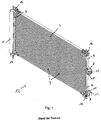
- Fig. 1 is a view of a known from the prior art heat exchanger 1 is shown. Between two headers 4, a plurality of tubes 3 are arranged. Between the tubes 3, corrugated fins, not shown, are formed of aluminum, which connect the tubes 3 both mechanically and thermally. The corrugated fins serve to increase the surface of the heat exchanger 1 and thereby increase the heat transfer.
- a connection device 8 On the right hand manifold 4 is an in Fig. 1 not shown inlet opening 6 and an outlet opening 7, not shown, which are each surrounded by a connection device 8 or closed. By means of the connection device 8, a line (not shown) is connected to the heat exchanger 1.
- the heat exchanger 1 serves as a refrigerant condenser 2 in an automotive air conditioning system.
- the heat exchanger 1 according to the invention as a refrigerant condenser 2 substantially corresponds to the in Fig. 1 Only the connection devices 8 of the heat exchanger 1 have a different structure and are in the Fig. 2 to 4 displayed.
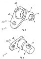
- the connection device 8 has a connection pipe socket 9 and a connection plate 10.
- the connection pipe socket 9 is produced by means of reverse extrusion from a first workpiece blank and has two sections with a different diameter.
- the connection pipe socket 9 points at one, in Fig. 2 shown above a connection opening 11 and a second end of the connecting pipe socket 9 has no opening, ie is closed. In the region of the end of the connection pipe socket 9 without opening, a fluid opening 17 is formed on a wall.
- connection plate 10 has the connection opening 11 and a fastening opening 12 designed as a fastening bore 13.
- the connection pipe socket 9 is fastened in the region of its connection opening 11 to the connection opening 11 of the connection plate 10 by means of a press fit and preferably additionally by means of soldering.
- the connection plate 10 is produced by punching from a raw plate and the connection opening 11 and the mounting hole 13 are already made during punching out of the raw plate, so that thereby a low production cost for the connection plate 10 is obtained.
- connection plate 10 and the connecting pipe socket 9 have a small thickness, for. B. of 0.3 mm or 0.2 mm.
- a low material requirement is required in the production of the connection device 8.
- connection pipe socket 9 and the connection plate 10 is generally used aluminum.
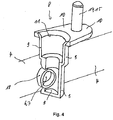
- connection device 8 is fastened with the fluid opening 17 on a passage 18 of the collecting pipe 4 ( Fig. 4 ).
- the tubes 3, as well as the not shown interposed corrugated fins and the manifold 4 and the reservoir 5 of the heat exchanger 1 are plated on the surface with solder.
- an inlet opening 6 and an outlet opening 7 are each incorporated with passages 18 at a collecting pipe 4.
- connection device 8 is fastened to the fluid opening 17.
- the fluid opening 17 is attached to the passage 18 by means of graining.
- the heat exchanger 1 comprising the tubes 3, the corrugated fins, the two manifolds 4, the collecting container 5 and the two connection devices 8 are introduced into a soldering oven for soldering. Due to the plating of the components of the heat exchanger 1 in particular also of the manifold 4 with the passage 18, the connection device 8 is soldered to the fluid opening 17 with the passage 18 of the manifold 4 by means of soldering. This is a fluid-tight Connection between the connection device 8 and the collecting pipe 4.
- connection opening 11 on the connection device 8 can be introduced or discharged through the connection opening 11 on the connection device 8, which then flows in or out through the connection pipe connection 9 and subsequently the connection pipe connection 9 at the fluid opening 17 leaves or flows back there and flows through the inlet or outlet port 6, 7 in the manifold 4 or flows out.
- connection plate 10 of the connection device 8 On the connection plate 10 of the connection device 8, a line, not shown, to be attached to the line in the refrigerant in the connection pipe socket 9 or divert.
- a fastening device 14 designed as a screw 15 is fastened to the fastening opening 12 by means of screws.
- the device on the line (not shown) in this case has a correspondingly formed counter-fastening device (not shown), for example a thread or a snap closure, so that thereby the device of the line, not shown, can be mechanically and also fluid-tightly fastened to the connection device 8.
- the screw 15 consists of iron, which is provided with a corrosion protection or a corrosion coating.
- the screw 15 is attached to the connector 8 only after brazing in the brazing furnace in which temperatures in the range of about 700 ° C are present. If, in the manufacture of the connection device 8, the screw 15 is already fastened to the connection plate 10 before soldering in the soldering oven, the screw 15 is to be made of stainless steel, because a screw made of iron with a corrosion coating does not meet the high temperatures in the soldering oven of about 700 ° C. withstand.
- connection device 8 namely the connection plate 10 and the connection pipe socket 9
- connection plate 10 and the connection pipe socket 9 are produced by extrusion and stamping and have a small wall thickness.
- a low material requirement for the connection plate 10 and the connection pipe socket 9 made of aluminum is required.
- the manufacturing costs can thus both be reduced because a low material requirement for the connection pipe socket 9 and the connection plate 10 is required and also little manufacturing steps are required.
Landscapes
- Engineering & Computer Science (AREA)
- Physics & Mathematics (AREA)
- Thermal Sciences (AREA)
- Mechanical Engineering (AREA)
- General Engineering & Computer Science (AREA)
- Air-Conditioning For Vehicles (AREA)
- Heat-Exchange Devices With Radiators And Conduit Assemblies (AREA)
Description
Die Erfindung betrifft einen Wärmeübertrager gemäß dem Oberbegriff des Anspruches 1, ein Verfahren zur Herstellung eines Wärmeübertragers gemäß dem Oberbegriff des Anspruches 6 und eine Kraftfahrzeugklimaanlage. Solch ein Wärmeübertrager ist aus
Wärmeübertrager werden für verschiedenste technische Anwendungen zum Kühlen und/oder zum Erwärmen von Fluiden benutzt. Dabei wird durch den Wärmeübertrager ein zu kühlendes oder zu erwärmendes Fluid geleitet und mittels eines den Wärmeübertrager umströmenden Fluids kann das Fluid in dem Wärmeübertrager gekühlt oder erwärmt werden. Wärmeübertrager weisen dabei im Allgemeinen eine Vielzahl an Rohre auf, die mechanisch und hydraulisch mit zwei Sammelrohren jeweils an den Enden der Rohre verbunden sind. Dadurch besteht eine hydraulische Verbindung zwischen den beiden Sammelrohren und den Rohren. Zwischen den Rohren, die insbesondere als Flachrohre ausgebildet sind, befinden sich im Allgemeinen Wellrippen. An dem Sammelrohr ist eine Einlassöffnung und eine Auslassöffnung zum Einleiten und Ausleiten des zu kühlenden oder zu erwärmenden Fluides angeordnet. Dabei befindet sich an der Einlassöffnung und an der Auslassöffnung jeweils eine Anschlusseinrichtung zum Anschluss einer Leitung mit einer Anschlussöffnung und einer Befestigungseinrichtung für die Leitung oder eine an der Leitung angeordnete Einrichtung. Das ein- oder auszuleitende Fluid wird somit zunächst von der Leitung durch die Anschlusseinrichtung und dann von der Anschlusseinrichtung in die Ein- oder Auslassöffnung an dem Sammelrohr geleitet. Wärmeübertrager können dabei auch als Kältemittelkondensatoren in Kraftfahrzeugklimaanlagen eingesetzt werden und dienen zum Kühlen und Verflüssigen eines zu kühlenden Fluides, nämlich Kältemittel, das durch den Kältemittelkondensator geleitet wird.Heat exchangers are used for various technical applications for cooling and / or for heating fluids. In this case, a fluid to be cooled or heated to be heated by the heat exchanger and by means of a heat transfer fluid flowing around the fluid in the heat exchanger can be cooled or heated. Heat exchangers generally have a multiplicity of tubes, which are mechanically and hydraulically connected to two manifolds at the ends of the tubes. This creates a hydraulic connection between the two headers and the pipes. Between the tubes, which are designed in particular as flat tubes, are generally corrugated fins. At the manifold is an inlet port and an outlet port for introducing and discharging the fluid to be cooled or heated arranged. In each case, a connection device for connecting a line to a connection opening and a fastening device for the line or a device arranged on the line is located at the inlet opening and at the outlet opening. The incoming or outgoing fluid is thus first passed from the line through the connection device and then from the connection device into the inlet or outlet opening on the collection tube. Heat exchangers can also be used as refrigerant condensers in motor vehicle air conditioners and are used for cooling and liquefying a fluid to be cooled, namely refrigerant, which is passed through the refrigerant condenser.
Die Anschlusseinrichtungen für den Wärmeübertrager werden hergestellt, indem aus einem mittels Extrudieren hergestelltem Vollprofil oder Stab die einzelnen Anschlusseinrichtungen abgeschnitten werden. In diese abgeschnittenen Teile wird anschließend spanabhebend, beispielsweise mittels Bohren oder Fräsen, eine Anschlussöffnung und eine Fluidöffnung eingearbeitet. Ferner wird eine Befestigungsbohrung eingearbeitet und in die Befestigungsbohrung wird nach dem Einarbeiten eines Gewindes beispielsweise eine Schraube eingeschraubt. Mittels der Schraube als Befestigungseinrichtung kann eine Leitung oder eine Einrichtung an der Leitung an der Anschlusseinrichtung befestigt werden. An dem Sammelrohr ist an den Ein- und Auslassöffnungen jeweils ein Durchzug ausgebildet und der Durchzug wird in die Fluidöffnung der Anschlusseinrichtung eingefügt und anschließend angelötet. Die Anschlusseinrichtung ist damit in der Herstellung aufwendig und teuer. Aufgrund der Verwendung eines mittels Extrudieren hergestellten Vollprofiles bei der Herstellung der Anschlusseinrichtung weist die Anschlusseinrichtung einen hohen Materialbedarf auf und aufgrund der hohen Kosten für dieses Material, es handelt sich im Allgemeinen um Aluminium, entstehen alleine deshalb hohe Kosten. Ferner werden für das spanabhebende Bearbeiten der Anschlusseinrichtung viele Fertigungsschritte benötigt, so dass auch dadurch hohe Kosten bei der Herstellung der Anschlusseinrichtung nachteiligerweise anfallen.The connection devices for the heat exchanger are produced by cutting off the individual connection devices from a solid profile or rod produced by means of extrusion. In these cut parts is then machined, for example by drilling or milling, a connection opening and a fluid opening incorporated. Furthermore, a mounting hole is incorporated and, for example, a screw is screwed into the mounting hole after incorporating a thread. By means of the screw as a fastening device, a line or a device can be attached to the line to the connection device. At the collecting pipe, a passage is formed at the inlet and outlet openings and the passage is inserted into the fluid opening of the connection device and then soldered. The connection device is thus complicated to manufacture and expensive. Due to the use of a full profile produced by means of extrusion in the production of the connection device, the connection device has a high material requirement and due to the high cost of this material, it is generally aluminum, high cost therefore arise alone. Furthermore, many manufacturing steps are required for the machining of the connection device required, so that this also incurs high costs in the production of the connection device disadvantageously.
Die Aufgabe der vorliegenden Erfindung besteht deshalb darin einen Wärmeübertrager, ein Verfahren zur Herstellung eines Wärmeübertragers und eine Kraftfahrzeugklimaanlage zur Verfügung zu stellen, bei dem eine Anschlusseinrichtung einen geringen Materialbedarf aufweist und die Herstellung der Anschlusseinrichtung einfach und preiswert mit wenigen Herstellungsschritten ist.The object of the present invention is therefore to provide a heat exchanger, a method for producing a heat exchanger and a motor vehicle air conditioning system, in which a connection device has a low material requirement and the production of the connection device is simple and inexpensive with only a few production steps.
Diese Aufgabe wird gelöst mit einem Wärmeübertrager nach dem Anspruch 1. Die Anschlusseinrichtung umfasst in vorteilhafterweise somit einen Anschlussrohrstutzen, der kein Vollprofil gemäß der Ausbildung der Anschlusseinrichtung im Stand der Technik ist. Dadurch kann Material bei der Herstellung für die Anschlusseinrichtung eingespart werden.This object is achieved with a heat exchanger according to claim 1. The connection device thus advantageously comprises a connection pipe socket which is not a solid profile according to the design of the connection device in the prior art. As a result, material can be saved during production for the connection device.
Insbesondere umfasst die Anschlusseinrichtung eine Anschlussplatte mit einer Anschlussöffnung und der Anschlussrohrstutzen ist an der Anschlussöffnung mit der Anschlussplatte verbunden und/oder ein Ende des Anschlussrohrstutzens bildet die Anschlussöffnung. Aufgrund der Ausbildung einer Anschlussplatte an der Anschlusseinrichtung wird für die Anschlusseinrichtung ein geringer Materialbedarf bei der Herstellung benötigt. Die Anschlussplatte dient dabei zum Anschluss der Leitung an der Anschlusseinrichtung, so dass dadurch eine großflächige Auflagefläche für eine Einrichtung an dem Rohr vorliegt, ohne dass dadurch ein hoher Materialbedarf erforderlich ist, weil die Anschlussplatte lediglich eine Platte mit einer geringen Materialdicke ist und kein Vollprofil.In particular, the connection device comprises a connection plate with a connection opening and the connection pipe connection piece is connected to the connection plate at the connection opening and / or one end of the connection connection piece forms the connection opening. Because of the training a connection plate on the connection device, a low material requirement for the connection device is required in the production. In this case, the connection plate serves to connect the line to the connection device, so that there is a large contact surface for a device on the tube, without requiring a high material requirement because the connection plate is merely a plate with a small material thickness and not a solid profile.
In einer weiteren Ausgestaltung beträgt die Dicke wenigstens einer Wandung des Anschlussrohrstutzens und/oder der Anschlussplatte weniger als 2 cm, 1 cm, 0,5 cm oder 0,3 cm. Aufgrund der Dicke der wenigstens einen Wandung wird somit wenig Material für die Anschlusseinrichtung benötigt. Die wenigstens eine Anschlusseinrichtung besteht vorzugsweise wenigstens teilweise, insbesondere vollständig aus Metall, beispielsweise Aluminium oder Stahl.In a further embodiment, the thickness of at least one wall of the connection pipe socket and / or the connection plate is less than 2 cm, 1 cm, 0.5 cm or 0.3 cm. Due to the thickness of the at least one wall thus little material is required for the connection device. The at least one connection device preferably consists at least partially, in particular completely of metal, for example aluminum or steel.
In einer ergänzenden Ausführungsform steht die Anschlussplatte im Wesentlichen senkrecht auf einer Achse des Anschlussrohrstutzens und/oder die Anschlussplatte ist mit einer Befestigungsöffnung, insbesondere Befestigungsbohrung, versehen und in der Befestigungsöffnung ist die Befestigungseinrichtung, z. B. eine Schraube oder ein Bolzen, befestigt zum Befestigen der Leitung an der Anschlusseinrichtung. Im Wesentlichen bedeutet dabei, dass die Achse des Anschlussrohrstutzens mit einer Abweichung von weniger als 30°, 20° oder 10° senkrecht zu der Anschlussplatte, d. h. einer Ebene der Anschlussplatte, steht. Die Ebene der Anschlussplatte ist dabei aufgrund der im Wesentlichen ebenen Ausbildung der Anschlussplatte eine Ebene, welche parallel zu der größten Ausdehnung der Anschlussplatte ausgerichtet ist und/oder parallel zu der größten ebenen Teiloberfläche der Anschlussplatte ausgerichtet ist.In a supplementary embodiment, the connection plate is substantially perpendicular to an axis of the connection pipe socket and / or the connection plate is provided with a mounting opening, in particular mounting hole, and in the mounting opening, the fastening device, for. As a screw or a bolt, attached for attaching the line to the connection device. Essentially, this means that the axis of the connection pipe socket is at a deviation of less than 30 °, 20 ° or 10 ° perpendicular to the connection plate, ie a plane of the connection plate. Due to the substantially planar design of the connection plate, the plane of the connection plate is a plane which is aligned parallel to the largest extension of the connection plate and / or is aligned parallel to the largest planar partial surface of the connection plate.
Vorzugsweise umfasst der Wärmeübertrager einen Sammelbehälter mit einem Trockner und/oder einem Filter und/oder der Anschlussrohrstutzen ist mit einer Fluidöffnung versehen. Bei der Ausbildung des Wärmeübertragers als Kältemittelkondensator umfasst der Wärmeübertrager den Sammelbehälter mit dem Trockner und/oder dem Filter. Das Sammelrohr weist einen Durchzug auf und in der Fluidöffnung des Anschlussrohrstutzens ist der Durchzug angeordnet, so dass dadurch eine mechanische Verbindung zwischen der Begrenzung der Fluidöffnung an dem Anschlussrohrstutzen und dem Durchzug an dem Sammelrohr besteht.Preferably, the heat exchanger comprises a collecting container with a dryer and / or a filter and / or the connection pipe socket is provided with a fluid opening. In the formation of the heat exchanger as a refrigerant condenser, the heat exchanger comprises the collecting container with the dryer and / or the filter. The collecting pipe has a passage and in the fluid opening of the connecting pipe connection, the passage is arranged, so that thereby a mechanical connection between the boundary of the fluid opening at the connection pipe socket and the passage to the collecting pipe consists.
Erfindungsgemäßes Verfahren zur Herstellung eines Wärmeübertragers, in dieser Schutzrechtsanmeldung beschriebenen Wärmeübertragers, zum Kühlen oder Erwärmen eines durch den Wärmeübertrager durchzuleitenden Fluides, insbesondere Kältemittelkondensator für eine Kraftfahrzeugklimaanlage, mit den Schritten: zur Verfügung stellen von Rohren, zur Verfügung stellen von wenigstens einem Sammelrohr mit Öffnungen, Anordnen der Rohre in den Öffnungen des wenigstens einen Sammelrohres, Herstellen wenigstens einer Anschlusseinrichtung zum Anschluss einer Leitung für das Fluid mit einer Anschlussöffnung und vorzugsweise einer Befestigungseinrichtung für die Leitung, Verbinden der Rohre, des wenigstens einen Sammelrohres und vorzugsweise der wenigstens einen Anschlusseinrichtung, insbesondere mittels Löten in einem Lötofen, so dass diese mechanisch miteinander verbunden sind und eine fluidleitende Verbindung zwischen den Rohren, dem wenigstens einen Sammelrohr und der wenigstens einen Anschlusseinrichtung besteht, wobei die wenigstens eine Anschlusseinrichtung mit Druckumformen, beispielsweise mit Fließpressen, insbesondere Rückwärtsfließpressen, und/oder Tiefziehen, aus wenigstens einem Werkstückrohling einteilig hergestellt wird. Aufgrund der Herstellung der wenigstens einen Anschlusseinrichtung mit Fließpressen, insbesondere Rückwärtsfließpressen und/oder Tiefziehen, kann eine Anschlusseinrichtung aus einem Werkstückrohling in einfacher Weise hergestellt werden, der geringe Wandstärken aufweist und somit ein geringer Materialbedarf bei der Herstellung der wenigstens einen Anschlusseinrichtung besteht. Damit kann die wenigstens eine Anschlusseinrichtung preiswert mit einem geringen Materialbedarf, beispielsweise Aluminium, hergestellt werden.A method according to the invention for producing a heat exchanger, heat exchanger described in this patent application, for cooling or heating a fluid to be passed through the heat exchanger, in particular a refrigerant condenser for an automotive air conditioning system, comprising the steps of: providing tubes, providing at least one collecting tube with openings, Arranging the tubes in the openings of the at least one collecting tube, producing at least one connecting device for connecting a line for the fluid with a connection opening and preferably a fastening device for the line, connecting the tubes, the at least one collecting tube and preferably the at least one connecting device, in particular by means of brazing in a brazing furnace, so that they are mechanically connected to one another and a fluid-conducting connection between the tubes, the at least one collecting tube and the at least one connecting device, wherein the at least one connecting device with pressure forming, for example with extrusion, especially reverse extrusion, and / or deep drawing, from at least one workpiece blank is made in one piece. Due to the production of the at least one connection device with extruding, in particular backward extrusion and / or deep drawing, a connection device can be produced from a workpiece blank in a simple manner, which has low wall thicknesses and thus there is a low material requirement in the production of the at least one connection device. Thus, the at least one connection device can be produced inexpensively with a low material requirement, for example aluminum.
An einer weiteren Ausführungsform wird aus einem, vorzugsweise nur einem, Werkstückrohling ein Anschlussrohrstutzen mit Fließpressen, insbesondere mit Rückwärtsfließpressen, hergestellt und in den Anschlussrohrstutzen wird eine Fluidöffnung, insbesondere Fluidbohrung, eingearbeitet. Bei der Herstellung der wenigstens einen Anschlusseinrichtung wird aus einem ersten Werkstückrohling mittels Rückwärtsfließpressen zunächst ein Anschlussrohrstutzen hergestellt. Der Anschlussrohrstutzen weist dabei vorzugsweise zwei Abschnitte mit einem unterschiedlichen Durchmesser auf. In diesen mittels Rückwärtsfließpressen hergestellten Anschlussrohrstutzen, der an einem Ende offen ist und dort eine Anschlussöffnung aufweist und am anderen Ende keine Öffnung aufweist, d. h. verschlossen ist, wird im Bereich bzw. in der Nähe des Endes ohne der Öffnung senkrecht zu einer Achse des Anschlussrohrstutzens, d. h. radial, eine Fluidöffnung eingearbeitet. Die Fluidöffnung wird dabei vorzugsweise spanabhebend, beispielsweise mittels Bohren oder Fräsen, in den mittels Rückwärtsfließpressen hergestellten Anschlussrohrstutzen eingearbeitet.In a further embodiment, a connection pipe socket with extrusions, in particular with backward extrusion presses, is produced from one, preferably only one, workpiece blank, and a fluid opening, in particular a fluid bore, is worked into the connection pipe socket. In the production of the at least one connection device, a connection pipe socket is first produced from a first workpiece blank by means of backward extrusion. The connection pipe socket preferably has two sections with a different diameter. In these connection pipe stub made by means of backward extrusion, which is open at one end and has a connection opening and has no opening at the other end, ie is closed, is in the area or in the vicinity of the end without the opening perpendicular to an axis of the connection pipe socket, ie radially, incorporated a fluid opening. The fluid opening is preferably machined, for example by means of drilling or milling, incorporated into the connection pipe socket produced by means of backward extrusion.
Insbesondere wird eine Anschlussplatte mit einer Anschlussöffnung und einer Befestigungsöffnung zur Verfügung gestellt, vorzugsweise wird die Anschlussplatte mit Stanzen aus einer Rohplatte hergestellt, und der Anschlussrohrstutzen wird in der Anschlussöffnung der Anschlussplatte befestigt. Aus einer beispielsweise mittels Walzen hergestellten Metallrohplatte werden die Anschlussplatten aus der Metallrohplatte ausgestanzt, so dass in einfacher Weise die Anschlussplatte mit einem geringen Fertigungsaufwand hergestellt bzw. zur Verfügung gestellt werden kann. Dabei wird in diese ausgestanzte Anschlussplatte beim Ausstanzen die Anschlussöffnung und die Befestigungsöffnung eingestanzt oder nach dem Ausstanzen wird in die ausgestanzte Anschlussplatte die Auslassöffnung und/oder die Befestigungsöffnung spanabhebend, beispielsweise mittels Bohren oder Fräsen, eingearbeitet. Anschließend wird der mittels Fließpressen hergestellte Anschlussrohrstutzen an der Anschlussöffnung der Anschlussplatte befestigt. Dies wird beispielsweise stoffschlüssig und/oder kraftschlüssig und/oder formschlüssig ausgeführt. Der Anschlussrohrstutzen kann beispielsweise mittels eines Presssitzes in der Anschlussöffnung der Anschlussplatte befestigt werden. Ergänzend kann auch in einem nachfolgenden Arbeitsgang mittels Löten der Anschlussrohrstutzen an der Anschlussplatte befestigt werden.In particular, a connection plate with a connection opening and a fastening opening is provided, preferably the connection plate is produced with punching from a raw plate, and the connection pipe connection piece is fastened in the connection opening of the connection plate. The connecting plates are punched out of the metal blank plate from a metal blank plate produced, for example, by means of rolling, so that the connecting plate can be produced or made available in a simple manner with a low manufacturing outlay. In this case, the connection opening and the attachment opening is stamped into this punched-out connection plate during punching or after punching out the outlet opening and / or the attachment opening is machined, for example by means of drilling or milling, into the stamped connection plate. Subsequently, the connection pipe socket produced by extrusion is attached to the connection opening of the connection plate. This is performed for example cohesively and / or non-positively and / or positively. The connection pipe socket can be fixed for example by means of a press fit in the connection opening of the connection plate. In addition, in a subsequent operation by soldering the connection pipe socket can be attached to the connection plate.
In einer weiteren Ausgestaltung wird ein Sammelbehälter zur Verfügung gestellt und der Sammelbehälter, die Rohre, das wenigstens eine Sammelrohr und die wenigstens eine Anschlusseinrichtung werden miteinander verbunden, so dass diese mechanisch miteinander verbunden sind und eine fluidleitende Verbindung zwischen dem Sammelbehälter, den Rohren, dem wenigstens einen Sammelrohr und der wenigstens einen Anschlusseinrichtung besteht. Bei der Ausbildung des Wärmeübertragers als Kältemittelkondensator wird auch ein Sammelbehälter benötigt. In dem Sammelbehälter ist vorzugsweise ein Trockner und/oder ein Filter angeordnet.In a further embodiment, a collecting container is provided and the collecting container, the tubes, the at least one collecting tube and the at least one connecting device are connected to one another so that they are mechanically connected to one another and a fluid-conducting connection between the collecting container, the tubes, the at least a manifold and the at least one connection device consists. In the formation of the heat exchanger as a refrigerant condenser and a collection container is required. In the collecting container, a dryer and / or a filter is preferably arranged.
In einer ergänzenden Variante wird die wenigstens eine Anschlusseinrichtung mit einem Anschlussrohrstutzen und einer Anschlussplatte aus einem Werkstückrohling mit Tiefziehen hergestellt. Abweichend von dem oben beschriebenen Herstellungsverfahren kann somit die Anschlusseinrichtung mit dem Anschlussrohrstutzen und der Anschlussplatte auch aus nur einem Werkstückrohling mittels Tiefziehen hergestellt werden. Nach dem Tiefziehen weist die Anschlusseinrichtung bereits den Anschlussrohrstutzen und die Anschlussplatte auf und diese sind aufgrund der Herstellung aus nur einem Werkstückrohling bereits miteinander verbunden. Vorzugsweise wird nach dem Tiefziehen in die Anschlussplatte die Befestigungsöffnung und in den Anschlussrohrstutzen die Fluidöffnung eingearbeitet, beispielsweise spanabhebend, insbesondere mittels Bohren und/oder Fräsen.In a supplementary variant, the at least one connection device with a connection pipe socket and a connection plate is produced from a workpiece blank with deep drawing. Notwithstanding the manufacturing method described above, the connection device with the connection pipe socket and the connection plate can thus also be produced from only one workpiece blank by means of deep drawing. After deep-drawing, the connection device already has the connection pipe socket and the connection plate and these are already connected to one another due to the production of only one workpiece blank. Preferably, after the deep drawing into the connection plate, the fastening opening and in the connection pipe socket, the fluid opening is incorporated, for example by machining, in particular by means of drilling and / or milling.
In einer weiteren Variante wird in die Anschlussplatte eine Befestigungsöffnung, insbesondere Befestigungsbohrung, eingearbeitet und in der Befestigungsöffnung wird eine Befestigungseinrichtung, z. B. eine Schraube oder ein Bolzen, befestigt. In die Befestigungsöffnung an der Anschlussplatte wird eine Befestigungseinrichtung, beispielsweise eine Schraube oder Bolzen, befestigt, vorzugsweise eingeschraubt, indem vorher in die Befestigungsöffnung ein Gewinde eingearbeitet worden ist oder beim Einschrauben der Schraube in die Befestigungsöffnung das Gewinde an der Anschlussplatte selbsttätig von dem Gewinde der Schraube herstellt wird. Mittels dieser Schraube oder dem Bolzen als Befestigungseinrichtung kann eine Leitung an der Anschlusseinrichtung befestigt werden. Hierzu weist die Leitung an dem Ende eine entsprechende Einrichtung auf und an dieser Einrichtung ist eine entsprechende Gegenbefestigungseinrichtung angeordnet, mittels der die Einrichtung an der Leitung an der Befestigungseinrichtung befestigt werden kann. Die Gegenbefestigungseinrichtung ist dabei an ein entsprechendes Gewinde, in das die Schraube an der Anschlussplatte eingeschraubt werden kann. Die Leitung wird dabei fluidleitend mit der Anschlussöffnung der Anschlusseinrichtung verbunden.In a further variant, a fastening opening, in particular fastening bore, is incorporated in the connecting plate and in the fastening opening is a fastening device, for. As a screw or a bolt attached. In the mounting hole on the terminal plate, a fastening device, such as a screw or bolt, attached, preferably screwed by previously been incorporated into the mounting hole a thread or when screwing the screw into the mounting hole, the thread on the terminal plate automatically from the thread of the screw is produced. By means of this screw or the bolt as a fastening device, a line can be attached to the connection device. For this purpose, the line at the end of a corresponding device and on this device a corresponding counter-fastening device is arranged, by means of which the device can be attached to the line to the fastening device. The counter-fastening device is in this case to a corresponding thread into which the screw is screwed to the connection plate can be. The line is thereby fluidly connected to the connection opening of the connection device.
In einer weiteren Ausgestaltung wird in das wenigstens eine Sammelrohr und/oder in den Sammelbehälter eine Einlassöffnung und/oder eine Auslassöffnung eingearbeitet, vorzugsweise wird an der Einlassöffnung und/oder der Auslassöffnung ein Durchzug eingearbeitet, und die wenigstens eine Anschlusseinrichtung, insbesondere die Fluidöffnung des Anschlussrohrstutzens, wird mit dem wenigstens einen Sammelrohr und/oder dem Sammelbehälter an der Einlassöffnung und/oder der Auslassöffnung verbunden, insbesondere in einem Lötofen angelötet und/oder angekörnt.In a further embodiment, an inlet opening and / or an outlet opening is incorporated in the at least one collecting tube and / or in the collecting container, a passage is preferably incorporated at the inlet opening and / or the outlet opening, and the at least one connection device, in particular the fluid opening of the connecting pipe connection , is connected to the at least one collecting tube and / or the collecting container at the inlet opening and / or the outlet opening, in particular soldered in a soldering oven and / or grained.
Insbesondere wird der Durchzug an der Einlassöffnung und/oder der Auslassöffnung in die Fluidöffnung des Anschlussrohrstutzens eingefügt.In particular, the passage at the inlet opening and / or the outlet opening is inserted into the fluid opening of the connection pipe socket.
Eine erfindungsgemäße Kraftfahrzeugklimaanlage umfasst einen in dieser Schutzrechtsanmeldung beschriebenen Wärmeübertrager.An automotive air conditioning system according to the invention comprises a heat exchanger described in this patent application.
In einer weiteren Ausgestaltung umfasst die Kraftfahrzeugklimaanlage einen Kältemittelverdampfer und/oder einen Kältemittelkondensator und/oder einen Verdichter und/oder eine Steuerungseinheit und/oder ein Gebläse.In a further embodiment, the motor vehicle air conditioning system comprises a refrigerant evaporator and / or a refrigerant condenser and / or a compressor and / or a control unit and / or a blower.
In einer zusätzlichen Ausführungsform sind der Kältemittelkondensator und/oder der Kältemittelverdampfer als ein in dieser Schutzrechtsanmeldung beschriebener Wärmeübertrager ausgebildet.In an additional embodiment, the refrigerant condenser and / or the refrigerant evaporator are designed as a heat exchanger described in this patent application.
In einer zusätzlichen Ausführungsform sind am Wärmeübertrager zwischen den Rohren Wellrippen angeordnet.In an additional embodiment, corrugated fins are arranged on the heat exchanger between the tubes.
In einer weiteren zweckmäßigen Ausgestaltung sind die Wellrippen an den Rohren stoffschlüssig, insbesondere mittels Löten, verbunden.In a further expedient embodiment, the corrugated fins on the tubes are materially connected, in particular by means of soldering.
Im Nachfolgenden wird ein Ausführungsbeispiel der Erfindung unter Bezugnahme auf die beigefügten Zeichnungen näher beschrieben. Es zeigt:
- Fig. 1
- eine Ansicht eines aus dem Stand der Technik bekannten Wärmeübertragers mit einer Anschlusseinrichtung,
- Fig. 2
- eine erste perspektivische Ansicht einer Anschlusseinrichtung für einen erfindungsgemäßen Wärmeübertrager,
- Fig. 3
- eine zweite perspektivische Ansicht der Anschlusseinrichtung gemäß
Fig. 2 und - Fig. 4
- eine dritte perspektivische Ansicht der Anschlusseinrichtung gemäß
Fig. 2 , wobei die Anschlusseinrichtung an einem Durchzug eines Sammelrohres eines erfindungsgemäßen Wärmeübertragers befestigt ist.
- Fig. 1
- a view of a known from the prior art heat exchanger with a connection device,
- Fig. 2
- a first perspective view of a connection device for a heat exchanger according to the invention,
- Fig. 3
- a second perspective view of the connection device according to
Fig. 2 and - Fig. 4
- a third perspective view of the connection device according to
Fig. 2 , wherein the connection device is attached to a passage of a manifold of a heat exchanger according to the invention.
In
Der erfindungsgemäße Wärmeübertrager 1 als Kältemittelkondensator 2 entspricht im Wesentlichen dem in
Die Dicken der Wände der Anschlussplatte 10 und des Anschlussrohrstutzens 9 weisen dabei eine geringe Dicke, z. B. von 0,3 mm oder 0,2 mm auf. Dadurch ist bei der Herstellung der Anschlusseinrichtung 8 ein geringer Materialbedarf erforderlich. Für die Herstellung des Anschlussrohrstutzens 9 und der Anschlussplatte 10 wird dabei im Allgemeinen Aluminium verwendet. Nach dem Verbinden der Anschlussplatte 10 mit dem Anschlussrohrstutzen 9 wird die Anschlusseinrichtung 8 mit der Fluidöffnung 17 an einem Durchzug 18 des Sammelrohres 4 befestigt (
An der Anschlussplatte 10 der Anschlusseinrichtung 8 ist eine nicht dargestellte Leitung zu befestigen, um durch die Leitung das Kältemittel in den Anschlussrohrstutzen 9 ein- oder auszuleiten. Hierzu wird nach dem Verlöten in dem Lötofen an der Anschlussplatte 10 eine als Schraube 15 ausgebildete Befestigungseinrichtung 14 an der Befestigungsöffnung 12 mittels Schrauben befestigt. Die Einrichtung an der Leitung (nicht dargestellt) weist dabei eine entsprechend ausgebildete Gegenbefestigungseinrichtung (nicht dargestellt) auf, beispielsweise ein Gewinde oder ein Schnappverschluss, so dass dadurch die nicht dargestellte Einrichtung der Leitung an der Anschlusseinrichtung 8 mechanisch und auch fluiddicht befestigt werden kann. Die Schraube 15 besteht dabei aus Eisen, die mit einem Korrosionsschutz bzw. einer Korrosionsbeschichtung versehen ist. Dies ist möglich, weil die Schraube 15 erst nach dem Löten in dem Lötofen, in dem Temperaturen im Bereich von ungefähr 700°C vorliegen, an der Anschlusseinrichtung 8 befestigt wird. Wird bei der Herstellung der Anschlusseinrichtung 8 die Schraube 15 bereits vor dem Löten in dem Lötofen an der Anschlussplatte 10 befestigt, ist die Schraube 15 aus Edelstahl auszuführen, weil eine Schraube aus Eisen mit einer Korrosionsbeschichtung den hohen Temperaturen im Lötofen von ungefähr 700°C nicht standhält.On the
Insgesamt betrachtet sind mit dem erfindungsgemäßen Wärmeübertrager 1 wesentliche Vorteile verbunden. Die Komponenten der Anschlusseinrichtung 8, nämlich die Anschlussplatte 10 und der Anschlussrohrstutzen 9, werden mittels Fließpressen und Stanzen hergestellt und weisen dabei eine geringe Wanddicke auf. Dadurch ist ein geringer Materialbedarf für die Anschlussplatte 10 und den Anschlussrohrstutzen 9 aus Aluminium erforderlich. Die Herstellungskosten können damit sowohl gesenkt werden, weil ein geringer Materialbedarf für den Anschlussrohrstutzen 9 und die Anschlussplatte 10 erforderlich ist und außerdem wenig Herstellungsschritte erforderlich sind.Overall, significant advantages are associated with the heat exchanger 1 according to the invention. The components of the
- 1 Wärmeübertrager1 heat exchanger
- 2 Kältemittelkondensator2 refrigerant condenser
- 3 Rohr3 pipe
- 4 Sammelrohr4 manifold
- 5 Sammelbehälter5 collection containers
- 6 Einlassöffnung6 inlet opening
- 7 Auslassöffnung7 outlet opening
- 8 Anschlusseinrichtung8 connection device
- 9 Anschlussrohrstutzen9 connection pipe socket
- 10 Anschlussplatte10 connection plate
- 11 Anschlussöffnung11 connection opening
- 12 Befestigungsöffnung12 mounting hole
- 13 Befestigungsbohrung13 mounting hole
- 14 Befestigungseinrichtung14 fastening device
- 15 Schraube15 screw
- 16 Fixierungseinrichtung16 fixing device
- 17 Fluidöffnung17 fluid opening
- 18 Durchzug18 draft
Claims (14)
- A heat exchanger (1) for cooling or heating a fluid to be conducted through the heat exchanger (1), in particular a refrigerant condenser (2) for a vehicle air-conditioning system, comprising- a plurality of tubes (3),- at least one collecting tube (4) with openings in which the tubes (3) are arranged for a hydraulic connection between the tubes (3) and the at least one collecting tube (4),- an inlet opening (6) for introducing a fluid,- an outlet opening (7) for discharging the fluid,- at least one connecting arrangement (8) for the connection of a line for the fluid to a connecting opening (11) and preferably a fixation arrangement (14) for the line,- wherein the at least one connecting arrangement (8) is arranged on the inlet opening (6) and/or the outlet opening (7),wherein the at least one connecting arrangement (8) comprises a connecting tube stud (9), wherein the connecting tube stud (9) is provided with a fluid opening (17) at the tube-shaped wall face thereof and a tube-shaped passage (18) on the inlet opening (6) and/or the outlet opening (7) on the at least one collecting tube (4) and/or the collecting container (5) is arranged in the fluid opening (17), wherein the connecting arrangement (8) is one piece, characterised in that the connecting arrangement (8) is produced by means of moulding.
- The heat exchanger according to claim 1, characterised in that the connecting arrangement (8) comprises a connecting plate (10) with a connecting opening (11) and the connecting tube stud (9) is connected to the connecting plate (10) on the connecting opening (11) and/or an end of the connecting tube stud (9) forms the connecting opening (11) .
- The heat exchanger according to claim 1 or 2, characterised in that the thickness of at least one wall of the connecting tube stud (9) and/or of the connecting plate (10) is less than 2 cm, 1 cm, 0.5 cm or 0.3 cm.
- The heat exchanger according to claim 2 or 3, characterised in that the connecting plate (10) stands essentially perpendicularly on an axis of the connecting tube stud (9) and/or the connecting plate (10) is provided with a fixation opening (12), in particular a fixation bore (13), and the fixation arrangement (14), e.g. a screw (15) or a bolt, is fixed in the fixation opening (12) in order to fix the line on the connecting arrangement (8).
- The heat exchanger according to one or more of the preceding claims, characterised in that the heat exchanger (1) comprises a collecting container (5) with a dryer and/or a filter.
- A method for producing a heat exchanger (1) according to one or more of the preceding claims, for cooling or heating a fluid to be conducted through the heat exchanger (1), in particular a refrigerant condenser (2) for a vehicle air-conditioning system, with the following steps:- providing tubes (3),- providing at least one collecting tube (4) with openings,- arranging the tubes (3) in the openings of the at least one collecting tube (4),- producing at least one connecting arrangement (8) for the connection of a line for the fluid to a connecting opening (11) and preferably a fixation arrangement (14) for the line,- connecting the tubes (3), the at least one collecting tube (4) and preferably the at least one connecting arrangement (8), in particular by means of soldering in a soldering furnace, so that they are mechanically connected to one another and there is a fluid-guiding connection between the tubes (3), the at least one collecting tube (4) and the at least one connecting arrangement (8),characterised in that the at least one connecting arrangement (8) is produced as one piece by means of compression moulding, for example by flow moulding, in particular by reverse flow moulding, and/or deep drawing, from at least one workpiece blank.
- The method according to claim 6, characterised in that a connecting tube stud (9) is made from a workpiece blank by means of flow moulding, in particular reverse flow moulding, and a fluid opening (17), in particular a fluid bore, is incorporated into the connecting tube stud (9).
- The method according to claim 7, characterised in that a connecting plate (10) with a connecting opening (11) and a fixation opening (12) is provided, wherein the connecting plate (10) is preferably produced by punching from a blank plate, and the connecting tube stud (9) is fixed in the connecting opening (11) of the connecting plate (10).
- The method according to one or more of claims 6 to 8, characterised in that a collecting container (5) is provided and the collecting container (5), the tubes (3), the at least one collecting tube (4) and the at least one connecting arrangement (8) are connected to one another so that they are mechanically connected to one another and there is a fluid-guiding connection between the collecting container (5), the tubes (3), the at least one collecting tube (4) and the at least one connecting arrangement (8).
- The method according to claim 6 or 9, characterised in that the at least one connecting arrangement (8) with a connecting tube stud (9) and a connecting plate (10) is produced from a workpiece blank by means of deep drawing.
- The method according to one or more of claims 6 to 10, characterised in that a fixation opening (12), in particular a fixation bore (13), is incorporated into the connecting plate (10) and a fixation arrangement (14), e.g. a screw (15) or a bolt, is fixed in the fixation opening (12).
- The method according to one or more of claims 6 to 11, characterised in that an inlet opening (6) and/or an outlet opening (7) is incorporated into the at least one collecting tube (4) and/or into the collecting container (5), preferably a passage (18) is incorporated on the inlet opening (6) and/or the outlet opening (7) and the at least one connecting arrangement (8), in particular the fluid opening (17) of the connecting tube stud (9) is connected to the at least one collecting tube (4) and/or the collecting container (5) on the inlet opening (6) and/or the outlet opening (7), in particular soldered in a soldering furnace and/or centre-punched.
- The method according to claim 12, characterised in that the passage (18) on the inlet opening (6) and/or the outlet opening (7) is inserted into the fluid opening (17) of the connecting tube stud (9).
- A vehicle air-conditioning system with a heat exchanger (1), characterised in that the heat exchanger (1) is designed as a heat exchanger (1) according to one or more of claims 1 to 6.
Priority Applications (1)
| Application Number | Priority Date | Filing Date | Title |
|---|---|---|---|
| EP09290872.2A EP2325593B1 (en) | 2009-11-19 | 2009-11-19 | Heat exchanger |
Applications Claiming Priority (1)
| Application Number | Priority Date | Filing Date | Title |
|---|---|---|---|
| EP09290872.2A EP2325593B1 (en) | 2009-11-19 | 2009-11-19 | Heat exchanger |
Publications (2)
| Publication Number | Publication Date |
|---|---|
| EP2325593A1 EP2325593A1 (en) | 2011-05-25 |
| EP2325593B1 true EP2325593B1 (en) | 2019-05-08 |
Family
ID=43305611
Family Applications (1)
| Application Number | Title | Priority Date | Filing Date |
|---|---|---|---|
| EP09290872.2A Active EP2325593B1 (en) | 2009-11-19 | 2009-11-19 | Heat exchanger |
Country Status (1)
| Country | Link |
|---|---|
| EP (1) | EP2325593B1 (en) |
Families Citing this family (1)
| Publication number | Priority date | Publication date | Assignee | Title |
|---|---|---|---|---|
| DE102011077755A1 (en) * | 2011-06-17 | 2012-12-20 | Behr Gmbh & Co. Kg | Terminal device for heat exchanger of heat exchanger device for vehicle, has stamping elements which are arranged between the terminals |
Family Cites Families (6)
| Publication number | Priority date | Publication date | Assignee | Title |
|---|---|---|---|---|
| JP2541409B2 (en) * | 1991-11-15 | 1996-10-09 | 日本電装株式会社 | Heat exchanger |
| US7229103B2 (en) * | 2002-06-25 | 2007-06-12 | T. Rad Co., Ltd | Heat exchanger tank-pipe connection structure |
| JP3894079B2 (en) * | 2002-09-17 | 2007-03-14 | 株式会社デンソー | Connection structure of heat exchanger header and piping |
| FR2875897A1 (en) * | 2004-09-28 | 2006-03-31 | Valeo Thermique Moteur Sas | HEAT EXCHANGER COMPRISING AT LEAST ONE FLANGE FOR A COLLECTOR OF THIS EXCHANGER |
| JP2006322636A (en) * | 2005-05-17 | 2006-11-30 | Valeo Thermal Systems Japan Corp | Heat exchanger |
| JP2007170717A (en) * | 2005-12-20 | 2007-07-05 | Denso Corp | Heat exchanger |
-
2009
- 2009-11-19 EP EP09290872.2A patent/EP2325593B1/en active Active
Non-Patent Citations (1)
| Title |
|---|
| None * |
Also Published As
| Publication number | Publication date |
|---|---|
| EP2325593A1 (en) | 2011-05-25 |
Similar Documents
| Publication | Publication Date | Title |
|---|---|---|
| DE102007007571B4 (en) | Pipe connecting device, pipe connecting structure of a heat exchanger and method of mounting a pipe to a heat exchanger | |
| EP1816425A2 (en) | Exhaust gas heat exchanger in an exhaust gas recirculation assembly | |
| WO2009007168A1 (en) | Heat exchanging system having a heat exchanger, and a method for manufacturing a heat exchanging system | |
| EP0374896A2 (en) | Flat tube condenser, manufacturing method and uses | |
| EP0566899B1 (en) | Heat exchanger, particularly evaporator | |
| EP1757888B1 (en) | Arrangement of two heat exchangers | |
| WO2009149838A1 (en) | Heat exchanger | |
| EP1439367B1 (en) | Heat exchanger comprising a connector joined to the header | |
| EP2293001A2 (en) | Heat exchanger with integrated cold storage | |
| DE102015111393A1 (en) | Device for heat transfer | |
| EP1482249A1 (en) | Manifold and method for manufacturing a manifold | |
| DE4330214B4 (en) | heat exchangers | |
| EP2325593B1 (en) | Heat exchanger | |
| DE102008007937A1 (en) | Two-piece header / manifold construction for a heat exchanger having flattened tubes | |
| DE102015111398A1 (en) | Device for heat transfer | |
| EP1568959B1 (en) | Brazed heat exchanger, especially condenser for automobiles | |
| EP1577627B1 (en) | Condenser for vehicle air conditioner | |
| EP1813902A1 (en) | Heat exchanger and fixing element. Process for making a heat exchanger and a fixing element | |
| DE102011088635A1 (en) | Heat exchanger i.e. refrigerant evaporator, for evaporating refrigerant in air-conditioning apparatus of motor car, has inflow pipe, and fluid gap interrupting connecting elements at inner and outer pipes that are bonded to each other | |
| WO2010000311A1 (en) | Heat exchanger block and a method for manufacturing a heat exchanger block | |
| DE102005028510A1 (en) | Adjustable internal heat exchanger | |
| EP1668304B1 (en) | Heat exchanging unit for motor vehicles | |
| DE102008058808A1 (en) | Heat exchanger assembly i.e. refrigerant condenser assembly, for motor vehicle air conditioning system, has connection formed by soldering for connection of separate tubular components of collector | |
| EP1229295B1 (en) | Heat exchanger core with several slotted headers | |
| EP1921411A1 (en) | Heat exchanger, in particular condenser for a car air conditioning system |
Legal Events
| Date | Code | Title | Description |
|---|---|---|---|
| PUAI | Public reference made under article 153(3) epc to a published international application that has entered the european phase |
Free format text: ORIGINAL CODE: 0009012 |
|
| AK | Designated contracting states |
Kind code of ref document: A1 Designated state(s): AT BE BG CH CY CZ DE DK EE ES FI FR GB GR HR HU IE IS IT LI LT LU LV MC MK MT NL NO PL PT RO SE SI SK SM TR |
|
| AX | Request for extension of the european patent |
Extension state: AL BA RS |
|
| 17P | Request for examination filed |
Effective date: 20111125 |
|
| RAP3 | Party data changed (applicant data changed or rights of an application transferred) |
Owner name: BEHR FRANCE HAMBACH S.A.R.L. |
|
| RAP1 | Party data changed (applicant data changed or rights of an application transferred) |
Owner name: MAHLE BEHR FRANCE HAMBACH S.A.S |
|
| 17Q | First examination report despatched |
Effective date: 20150605 |
|
| STAA | Information on the status of an ep patent application or granted ep patent |
Free format text: STATUS: EXAMINATION IS IN PROGRESS |
|
| GRAP | Despatch of communication of intention to grant a patent |
Free format text: ORIGINAL CODE: EPIDOSNIGR1 |
|
| STAA | Information on the status of an ep patent application or granted ep patent |
Free format text: STATUS: GRANT OF PATENT IS INTENDED |
|
| INTG | Intention to grant announced |
Effective date: 20181123 |
|
| GRAJ | Information related to disapproval of communication of intention to grant by the applicant or resumption of examination proceedings by the epo deleted |
Free format text: ORIGINAL CODE: EPIDOSDIGR1 |
|
| STAA | Information on the status of an ep patent application or granted ep patent |
Free format text: STATUS: EXAMINATION IS IN PROGRESS |
|
| GRAR | Information related to intention to grant a patent recorded |
Free format text: ORIGINAL CODE: EPIDOSNIGR71 |
|
| GRAS | Grant fee paid |
Free format text: ORIGINAL CODE: EPIDOSNIGR3 |
|
| STAA | Information on the status of an ep patent application or granted ep patent |
Free format text: STATUS: GRANT OF PATENT IS INTENDED |
|
| GRAA | (expected) grant |
Free format text: ORIGINAL CODE: 0009210 |
|
| STAA | Information on the status of an ep patent application or granted ep patent |
Free format text: STATUS: THE PATENT HAS BEEN GRANTED |
|
| INTC | Intention to grant announced (deleted) | ||
| INTG | Intention to grant announced |
Effective date: 20190327 |
|
| AK | Designated contracting states |
Kind code of ref document: B1 Designated state(s): AT BE BG CH CY CZ DE DK EE ES FI FR GB GR HR HU IE IS IT LI LT LU LV MC MK MT NL NO PL PT RO SE SI SK SM TR |
|
| REG | Reference to a national code |
Ref country code: GB Ref legal event code: FG4D Free format text: NOT ENGLISH |
|
| REG | Reference to a national code |
Ref country code: CH Ref legal event code: EP Ref country code: AT Ref legal event code: REF Ref document number: 1130833 Country of ref document: AT Kind code of ref document: T Effective date: 20190515 |
|
| REG | Reference to a national code |
Ref country code: DE Ref legal event code: R096 Ref document number: 502009015767 Country of ref document: DE Ref country code: IE Ref legal event code: FG4D Free format text: LANGUAGE OF EP DOCUMENT: GERMAN |
|
| REG | Reference to a national code |
Ref country code: NL Ref legal event code: MP Effective date: 20190508 |
|
| REG | Reference to a national code |
Ref country code: LT Ref legal event code: MG4D |
|
| PG25 | Lapsed in a contracting state [announced via postgrant information from national office to epo] |
Ref country code: ES Free format text: LAPSE BECAUSE OF FAILURE TO SUBMIT A TRANSLATION OF THE DESCRIPTION OR TO PAY THE FEE WITHIN THE PRESCRIBED TIME-LIMIT Effective date: 20190508 Ref country code: PT Free format text: LAPSE BECAUSE OF FAILURE TO SUBMIT A TRANSLATION OF THE DESCRIPTION OR TO PAY THE FEE WITHIN THE PRESCRIBED TIME-LIMIT Effective date: 20190908 Ref country code: NL Free format text: LAPSE BECAUSE OF FAILURE TO SUBMIT A TRANSLATION OF THE DESCRIPTION OR TO PAY THE FEE WITHIN THE PRESCRIBED TIME-LIMIT Effective date: 20190508 Ref country code: HR Free format text: LAPSE BECAUSE OF FAILURE TO SUBMIT A TRANSLATION OF THE DESCRIPTION OR TO PAY THE FEE WITHIN THE PRESCRIBED TIME-LIMIT Effective date: 20190508 Ref country code: SE Free format text: LAPSE BECAUSE OF FAILURE TO SUBMIT A TRANSLATION OF THE DESCRIPTION OR TO PAY THE FEE WITHIN THE PRESCRIBED TIME-LIMIT Effective date: 20190508 Ref country code: FI Free format text: LAPSE BECAUSE OF FAILURE TO SUBMIT A TRANSLATION OF THE DESCRIPTION OR TO PAY THE FEE WITHIN THE PRESCRIBED TIME-LIMIT Effective date: 20190508 Ref country code: NO Free format text: LAPSE BECAUSE OF FAILURE TO SUBMIT A TRANSLATION OF THE DESCRIPTION OR TO PAY THE FEE WITHIN THE PRESCRIBED TIME-LIMIT Effective date: 20190808 Ref country code: LT Free format text: LAPSE BECAUSE OF FAILURE TO SUBMIT A TRANSLATION OF THE DESCRIPTION OR TO PAY THE FEE WITHIN THE PRESCRIBED TIME-LIMIT Effective date: 20190508 |
|
| PG25 | Lapsed in a contracting state [announced via postgrant information from national office to epo] |
Ref country code: LV Free format text: LAPSE BECAUSE OF FAILURE TO SUBMIT A TRANSLATION OF THE DESCRIPTION OR TO PAY THE FEE WITHIN THE PRESCRIBED TIME-LIMIT Effective date: 20190508 Ref country code: GR Free format text: LAPSE BECAUSE OF FAILURE TO SUBMIT A TRANSLATION OF THE DESCRIPTION OR TO PAY THE FEE WITHIN THE PRESCRIBED TIME-LIMIT Effective date: 20190809 Ref country code: BG Free format text: LAPSE BECAUSE OF FAILURE TO SUBMIT A TRANSLATION OF THE DESCRIPTION OR TO PAY THE FEE WITHIN THE PRESCRIBED TIME-LIMIT Effective date: 20190808 |
|
| PG25 | Lapsed in a contracting state [announced via postgrant information from national office to epo] |
Ref country code: DK Free format text: LAPSE BECAUSE OF FAILURE TO SUBMIT A TRANSLATION OF THE DESCRIPTION OR TO PAY THE FEE WITHIN THE PRESCRIBED TIME-LIMIT Effective date: 20190508 Ref country code: RO Free format text: LAPSE BECAUSE OF FAILURE TO SUBMIT A TRANSLATION OF THE DESCRIPTION OR TO PAY THE FEE WITHIN THE PRESCRIBED TIME-LIMIT Effective date: 20190508 Ref country code: SK Free format text: LAPSE BECAUSE OF FAILURE TO SUBMIT A TRANSLATION OF THE DESCRIPTION OR TO PAY THE FEE WITHIN THE PRESCRIBED TIME-LIMIT Effective date: 20190508 Ref country code: EE Free format text: LAPSE BECAUSE OF FAILURE TO SUBMIT A TRANSLATION OF THE DESCRIPTION OR TO PAY THE FEE WITHIN THE PRESCRIBED TIME-LIMIT Effective date: 20190508 Ref country code: CZ Free format text: LAPSE BECAUSE OF FAILURE TO SUBMIT A TRANSLATION OF THE DESCRIPTION OR TO PAY THE FEE WITHIN THE PRESCRIBED TIME-LIMIT Effective date: 20190508 |
|
| REG | Reference to a national code |
Ref country code: DE Ref legal event code: R097 Ref document number: 502009015767 Country of ref document: DE |
|
| PG25 | Lapsed in a contracting state [announced via postgrant information from national office to epo] |
Ref country code: IT Free format text: LAPSE BECAUSE OF FAILURE TO SUBMIT A TRANSLATION OF THE DESCRIPTION OR TO PAY THE FEE WITHIN THE PRESCRIBED TIME-LIMIT Effective date: 20190508 Ref country code: SM Free format text: LAPSE BECAUSE OF FAILURE TO SUBMIT A TRANSLATION OF THE DESCRIPTION OR TO PAY THE FEE WITHIN THE PRESCRIBED TIME-LIMIT Effective date: 20190508 |
|
| PLBE | No opposition filed within time limit |
Free format text: ORIGINAL CODE: 0009261 |
|
| STAA | Information on the status of an ep patent application or granted ep patent |
Free format text: STATUS: NO OPPOSITION FILED WITHIN TIME LIMIT |
|
| PG25 | Lapsed in a contracting state [announced via postgrant information from national office to epo] |
Ref country code: TR Free format text: LAPSE BECAUSE OF FAILURE TO SUBMIT A TRANSLATION OF THE DESCRIPTION OR TO PAY THE FEE WITHIN THE PRESCRIBED TIME-LIMIT Effective date: 20190508 |
|
| 26N | No opposition filed |
Effective date: 20200211 |
|
| PG25 | Lapsed in a contracting state [announced via postgrant information from national office to epo] |
Ref country code: PL Free format text: LAPSE BECAUSE OF FAILURE TO SUBMIT A TRANSLATION OF THE DESCRIPTION OR TO PAY THE FEE WITHIN THE PRESCRIBED TIME-LIMIT Effective date: 20190508 |
|
| PG25 | Lapsed in a contracting state [announced via postgrant information from national office to epo] |
Ref country code: SI Free format text: LAPSE BECAUSE OF FAILURE TO SUBMIT A TRANSLATION OF THE DESCRIPTION OR TO PAY THE FEE WITHIN THE PRESCRIBED TIME-LIMIT Effective date: 20190508 |
|
| REG | Reference to a national code |
Ref country code: CH Ref legal event code: PL |
|
| PG25 | Lapsed in a contracting state [announced via postgrant information from national office to epo] |
Ref country code: LU Free format text: LAPSE BECAUSE OF NON-PAYMENT OF DUE FEES Effective date: 20191119 Ref country code: CH Free format text: LAPSE BECAUSE OF NON-PAYMENT OF DUE FEES Effective date: 20191130 Ref country code: MC Free format text: LAPSE BECAUSE OF FAILURE TO SUBMIT A TRANSLATION OF THE DESCRIPTION OR TO PAY THE FEE WITHIN THE PRESCRIBED TIME-LIMIT Effective date: 20190508 Ref country code: LI Free format text: LAPSE BECAUSE OF NON-PAYMENT OF DUE FEES Effective date: 20191130 |
|
| REG | Reference to a national code |
Ref country code: BE Ref legal event code: MM Effective date: 20191130 |
|
| GBPC | Gb: european patent ceased through non-payment of renewal fee |
Effective date: 20191119 |
|
| PG25 | Lapsed in a contracting state [announced via postgrant information from national office to epo] |
Ref country code: IE Free format text: LAPSE BECAUSE OF NON-PAYMENT OF DUE FEES Effective date: 20191119 Ref country code: GB Free format text: LAPSE BECAUSE OF NON-PAYMENT OF DUE FEES Effective date: 20191119 Ref country code: FR Free format text: LAPSE BECAUSE OF NON-PAYMENT OF DUE FEES Effective date: 20191130 |
|
| PG25 | Lapsed in a contracting state [announced via postgrant information from national office to epo] |
Ref country code: BE Free format text: LAPSE BECAUSE OF NON-PAYMENT OF DUE FEES Effective date: 20191130 |
|
| REG | Reference to a national code |
Ref country code: AT Ref legal event code: MM01 Ref document number: 1130833 Country of ref document: AT Kind code of ref document: T Effective date: 20191119 |
|
| PG25 | Lapsed in a contracting state [announced via postgrant information from national office to epo] |
Ref country code: AT Free format text: LAPSE BECAUSE OF NON-PAYMENT OF DUE FEES Effective date: 20191119 |
|
| PG25 | Lapsed in a contracting state [announced via postgrant information from national office to epo] |
Ref country code: CY Free format text: LAPSE BECAUSE OF FAILURE TO SUBMIT A TRANSLATION OF THE DESCRIPTION OR TO PAY THE FEE WITHIN THE PRESCRIBED TIME-LIMIT Effective date: 20190508 |
|
| PG25 | Lapsed in a contracting state [announced via postgrant information from national office to epo] |
Ref country code: IS Free format text: LAPSE BECAUSE OF FAILURE TO SUBMIT A TRANSLATION OF THE DESCRIPTION OR TO PAY THE FEE WITHIN THE PRESCRIBED TIME-LIMIT Effective date: 20190908 |
|
| PG25 | Lapsed in a contracting state [announced via postgrant information from national office to epo] |
Ref country code: HU Free format text: LAPSE BECAUSE OF FAILURE TO SUBMIT A TRANSLATION OF THE DESCRIPTION OR TO PAY THE FEE WITHIN THE PRESCRIBED TIME-LIMIT; INVALID AB INITIO Effective date: 20091119 Ref country code: MT Free format text: LAPSE BECAUSE OF FAILURE TO SUBMIT A TRANSLATION OF THE DESCRIPTION OR TO PAY THE FEE WITHIN THE PRESCRIBED TIME-LIMIT Effective date: 20190508 |
|
| PG25 | Lapsed in a contracting state [announced via postgrant information from national office to epo] |
Ref country code: MK Free format text: LAPSE BECAUSE OF FAILURE TO SUBMIT A TRANSLATION OF THE DESCRIPTION OR TO PAY THE FEE WITHIN THE PRESCRIBED TIME-LIMIT Effective date: 20190508 |
|
| PGFP | Annual fee paid to national office [announced via postgrant information from national office to epo] |
Ref country code: DE Payment date: 20231121 Year of fee payment: 15 |