EP2325552B1 - Collapsible light - Google Patents
Collapsible light Download PDFInfo
- Publication number
- EP2325552B1 EP2325552B1 EP10075729.3A EP10075729A EP2325552B1 EP 2325552 B1 EP2325552 B1 EP 2325552B1 EP 10075729 A EP10075729 A EP 10075729A EP 2325552 B1 EP2325552 B1 EP 2325552B1
- Authority
- EP
- European Patent Office
- Prior art keywords
- collar
- lighting device
- main body
- collapsible
- lamp head
- Prior art date
- Legal status (The legal status is an assumption and is not a legal conclusion. Google has not performed a legal analysis and makes no representation as to the accuracy of the status listed.)
- Active
Links
- 230000003213 activating effect Effects 0.000 claims description 2
- 230000033001 locomotion Effects 0.000 description 7
- ZPUCINDJVBIVPJ-LJISPDSOSA-N cocaine Chemical compound O([C@H]1C[C@@H]2CC[C@@H](N2C)[C@H]1C(=O)OC)C(=O)C1=CC=CC=C1 ZPUCINDJVBIVPJ-LJISPDSOSA-N 0.000 description 3
- 229910052736 halogen Inorganic materials 0.000 description 3
- 150000002367 halogens Chemical class 0.000 description 3
- 230000000694 effects Effects 0.000 description 2
- 238000005286 illumination Methods 0.000 description 2
- 239000002184 metal Substances 0.000 description 2
- 239000000356 contaminant Substances 0.000 description 1
- 238000004146 energy storage Methods 0.000 description 1
- 238000005188 flotation Methods 0.000 description 1
- 238000007373 indentation Methods 0.000 description 1
- 238000003780 insertion Methods 0.000 description 1
- 230000037431 insertion Effects 0.000 description 1
- 239000007788 liquid Substances 0.000 description 1
- 230000001681 protective effect Effects 0.000 description 1
Images


Classifications
-
- F—MECHANICAL ENGINEERING; LIGHTING; HEATING; WEAPONS; BLASTING
- F21—LIGHTING
- F21V—FUNCTIONAL FEATURES OR DETAILS OF LIGHTING DEVICES OR SYSTEMS THEREOF; STRUCTURAL COMBINATIONS OF LIGHTING DEVICES WITH OTHER ARTICLES, NOT OTHERWISE PROVIDED FOR
- F21V21/00—Supporting, suspending, or attaching arrangements for lighting devices; Hand grips
- F21V21/14—Adjustable mountings
- F21V21/145—Adjustable mountings for portable lighting devices
-
- F—MECHANICAL ENGINEERING; LIGHTING; HEATING; WEAPONS; BLASTING
- F16—ENGINEERING ELEMENTS AND UNITS; GENERAL MEASURES FOR PRODUCING AND MAINTAINING EFFECTIVE FUNCTIONING OF MACHINES OR INSTALLATIONS; THERMAL INSULATION IN GENERAL
- F16M—FRAMES, CASINGS OR BEDS OF ENGINES, MACHINES OR APPARATUS, NOT SPECIFIC TO ENGINES, MACHINES OR APPARATUS PROVIDED FOR ELSEWHERE; STANDS; SUPPORTS
- F16M11/00—Stands or trestles as supports for apparatus or articles placed thereon ; Stands for scientific apparatus such as gravitational force meters
- F16M11/02—Heads
- F16M11/04—Means for attachment of apparatus; Means allowing adjustment of the apparatus relatively to the stand
- F16M11/06—Means for attachment of apparatus; Means allowing adjustment of the apparatus relatively to the stand allowing pivoting
- F16M11/10—Means for attachment of apparatus; Means allowing adjustment of the apparatus relatively to the stand allowing pivoting around a horizontal axis
-
- F—MECHANICAL ENGINEERING; LIGHTING; HEATING; WEAPONS; BLASTING
- F16—ENGINEERING ELEMENTS AND UNITS; GENERAL MEASURES FOR PRODUCING AND MAINTAINING EFFECTIVE FUNCTIONING OF MACHINES OR INSTALLATIONS; THERMAL INSULATION IN GENERAL
- F16M—FRAMES, CASINGS OR BEDS OF ENGINES, MACHINES OR APPARATUS, NOT SPECIFIC TO ENGINES, MACHINES OR APPARATUS PROVIDED FOR ELSEWHERE; STANDS; SUPPORTS
- F16M11/00—Stands or trestles as supports for apparatus or articles placed thereon ; Stands for scientific apparatus such as gravitational force meters
- F16M11/20—Undercarriages with or without wheels
- F16M11/24—Undercarriages with or without wheels changeable in height or length of legs, also for transport only, e.g. by means of tubes screwed into each other
- F16M11/242—Undercarriages with or without wheels changeable in height or length of legs, also for transport only, e.g. by means of tubes screwed into each other by spreading of the legs
- F16M11/245—Members limiting spreading of legs, e.g. "umbrella legs"
-
- F—MECHANICAL ENGINEERING; LIGHTING; HEATING; WEAPONS; BLASTING
- F16—ENGINEERING ELEMENTS AND UNITS; GENERAL MEASURES FOR PRODUCING AND MAINTAINING EFFECTIVE FUNCTIONING OF MACHINES OR INSTALLATIONS; THERMAL INSULATION IN GENERAL
- F16M—FRAMES, CASINGS OR BEDS OF ENGINES, MACHINES OR APPARATUS, NOT SPECIFIC TO ENGINES, MACHINES OR APPARATUS PROVIDED FOR ELSEWHERE; STANDS; SUPPORTS
- F16M11/00—Stands or trestles as supports for apparatus or articles placed thereon ; Stands for scientific apparatus such as gravitational force meters
- F16M11/20—Undercarriages with or without wheels
- F16M11/24—Undercarriages with or without wheels changeable in height or length of legs, also for transport only, e.g. by means of tubes screwed into each other
- F16M11/26—Undercarriages with or without wheels changeable in height or length of legs, also for transport only, e.g. by means of tubes screwed into each other by telescoping, with or without folding
- F16M11/28—Undercarriages for supports with one single telescoping pillar
-
- F—MECHANICAL ENGINEERING; LIGHTING; HEATING; WEAPONS; BLASTING
- F16—ENGINEERING ELEMENTS AND UNITS; GENERAL MEASURES FOR PRODUCING AND MAINTAINING EFFECTIVE FUNCTIONING OF MACHINES OR INSTALLATIONS; THERMAL INSULATION IN GENERAL
- F16M—FRAMES, CASINGS OR BEDS OF ENGINES, MACHINES OR APPARATUS, NOT SPECIFIC TO ENGINES, MACHINES OR APPARATUS PROVIDED FOR ELSEWHERE; STANDS; SUPPORTS
- F16M11/00—Stands or trestles as supports for apparatus or articles placed thereon ; Stands for scientific apparatus such as gravitational force meters
- F16M11/20—Undercarriages with or without wheels
- F16M11/24—Undercarriages with or without wheels changeable in height or length of legs, also for transport only, e.g. by means of tubes screwed into each other
- F16M11/26—Undercarriages with or without wheels changeable in height or length of legs, also for transport only, e.g. by means of tubes screwed into each other by telescoping, with or without folding
- F16M11/32—Undercarriages for supports with three or more telescoping legs
-
- F—MECHANICAL ENGINEERING; LIGHTING; HEATING; WEAPONS; BLASTING
- F16—ENGINEERING ELEMENTS AND UNITS; GENERAL MEASURES FOR PRODUCING AND MAINTAINING EFFECTIVE FUNCTIONING OF MACHINES OR INSTALLATIONS; THERMAL INSULATION IN GENERAL
- F16M—FRAMES, CASINGS OR BEDS OF ENGINES, MACHINES OR APPARATUS, NOT SPECIFIC TO ENGINES, MACHINES OR APPARATUS PROVIDED FOR ELSEWHERE; STANDS; SUPPORTS
- F16M11/00—Stands or trestles as supports for apparatus or articles placed thereon ; Stands for scientific apparatus such as gravitational force meters
- F16M11/20—Undercarriages with or without wheels
- F16M11/24—Undercarriages with or without wheels changeable in height or length of legs, also for transport only, e.g. by means of tubes screwed into each other
- F16M11/38—Undercarriages with or without wheels changeable in height or length of legs, also for transport only, e.g. by means of tubes screwed into each other by folding, e.g. pivoting or scissors tong mechanisms
-
- F—MECHANICAL ENGINEERING; LIGHTING; HEATING; WEAPONS; BLASTING
- F16—ENGINEERING ELEMENTS AND UNITS; GENERAL MEASURES FOR PRODUCING AND MAINTAINING EFFECTIVE FUNCTIONING OF MACHINES OR INSTALLATIONS; THERMAL INSULATION IN GENERAL
- F16M—FRAMES, CASINGS OR BEDS OF ENGINES, MACHINES OR APPARATUS, NOT SPECIFIC TO ENGINES, MACHINES OR APPARATUS PROVIDED FOR ELSEWHERE; STANDS; SUPPORTS
- F16M13/00—Other supports for positioning apparatus or articles; Means for steadying hand-held apparatus or articles
- F16M13/04—Other supports for positioning apparatus or articles; Means for steadying hand-held apparatus or articles for supporting on, or holding steady relative to, a person, e.g. by chains, e.g. rifle butt or pistol grip supports, supports attached to the chest or head
-
- F—MECHANICAL ENGINEERING; LIGHTING; HEATING; WEAPONS; BLASTING
- F21—LIGHTING
- F21V—FUNCTIONAL FEATURES OR DETAILS OF LIGHTING DEVICES OR SYSTEMS THEREOF; STRUCTURAL COMBINATIONS OF LIGHTING DEVICES WITH OTHER ARTICLES, NOT OTHERWISE PROVIDED FOR
- F21V17/00—Fastening of component parts of lighting devices, e.g. shades, globes, refractors, reflectors, filters, screens, grids or protective cages
- F21V17/007—Fastening of component parts of lighting devices, e.g. shades, globes, refractors, reflectors, filters, screens, grids or protective cages with provision for shipment or storage
-
- F—MECHANICAL ENGINEERING; LIGHTING; HEATING; WEAPONS; BLASTING
- F21—LIGHTING
- F21V—FUNCTIONAL FEATURES OR DETAILS OF LIGHTING DEVICES OR SYSTEMS THEREOF; STRUCTURAL COMBINATIONS OF LIGHTING DEVICES WITH OTHER ARTICLES, NOT OTHERWISE PROVIDED FOR
- F21V21/00—Supporting, suspending, or attaching arrangements for lighting devices; Hand grips
- F21V21/14—Adjustable mountings
- F21V21/22—Adjustable mountings telescopic
-
- Y—GENERAL TAGGING OF NEW TECHNOLOGICAL DEVELOPMENTS; GENERAL TAGGING OF CROSS-SECTIONAL TECHNOLOGIES SPANNING OVER SEVERAL SECTIONS OF THE IPC; TECHNICAL SUBJECTS COVERED BY FORMER USPC CROSS-REFERENCE ART COLLECTIONS [XRACs] AND DIGESTS
- Y10—TECHNICAL SUBJECTS COVERED BY FORMER USPC
- Y10T—TECHNICAL SUBJECTS COVERED BY FORMER US CLASSIFICATION
- Y10T29/00—Metal working
- Y10T29/49—Method of mechanical manufacture
- Y10T29/49826—Assembling or joining
Definitions
- the Invention relates to collapsible structures, in particular a collapsible lighting device followint the features of claim 1, which can be transported to provide lighting in in areas where flashlights are unsatisfactory.
- Flashlights have been used extensively in areas where lighting is not available. In many circumstances, however, flashlights are inadequate because they fail to provide adequate lighting to accommodate the needs of workers, campers, or persons engaged in other activities. Portable lights which stand alone provide necessary levels of light while leaving workers and other individuals free hands to perform tasks and conduct other activities. Representative examples of such lights are known from patent documents US2005/117340 A1 , BE458242A , US2006/209547A1 or DE 29520042 .
- Portable lights tend to be bulky and large and inconvenient to carry.
- the invention disclosed herein provides a collapsible light in a form factor which is portable and easy to carry to provide light for many applications.
- Figure 1 shows a collapsible light 101 according to the invention in a substantially cylindrical form factor, resembling a a karooka, for easy transport.
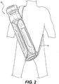
- Collapsible light 101 has attached to it a carrying strap, 103, to facilitate carrying the apelooka shaped collapsible light on one's back, as illustrated in Figure 2 .
- Figure 1 further shows securing strap 105.
- Securing strap 105 can be used as one way to secure the legs, as discussed further herein, to form an exterior portion of the cylindrical shape in the collapsed position. Other means for securing the legs in the collapsed position can also be used.
- Figure 1 further illustrates lamp head 107, which has sockets therein for illuminating elements. As shown in Figure 1 , lamp head 107 is tucked into a collar 109 to protect the lamp head when the light is in the collapsed position.
- Figure 3 illustrates an embodiment of a collapsible light according to the invention in the deployed position.
- the structure of a collapsible light according to the invention includes a main body 301 which mounts on top of a lower body serving as a battery compartment 303 to form a substantially cylindrical shape.
- the main body and battery compartment can be formed separately or as an integrated unit.
- Other shapes, such as triangular, square, oval and rectangular, may also be employed without departing from the scope of the invention.
- the invention also is not limited to any particular battery type.
- the battery can be rechargeable or non-rechargeable.
- Battery charging circuitry and a suitable plug to an external power source may be incorporated into the lower body battery compartment 303, or elsewhere in the light, as may be convenient. It is within the scope of the invention to provide illumination using an AC power source and/or one or more transformers.
- main body 301 can house electrical cables, such as a coiled electrical cable (not shown), to deliver electrical power to one or more illuminating elements, such as light emitting diodes, in the lamp head 107.
- electrical cables such as a coiled electrical cable (not shown)
- illuminating elements such as light emitting diodes
- Other types of illuminating elements such as incandescent, halogen or fluorescent light elements, may be used in lamp head 107, without departing from the scope and spirit of the invention.
- the main body 301 also accommodates one or more telescoping members, which allow the lamp head 107 of the collapsible light according to the invention to be set at different heights to provide light over different size areas.
- collar 109 is a two part hollow cylindrical member, including upper collar portion 305 and lower collar portion 307.
- the upper and lower collar portions, 305 and 307, may be formed separately and connected together or may be formed as an integrated unit.
- Upper collar portion 305 has a wider outer diameter than lower collar portion 307.
- One or more legs 309 are pivotally attached or hinged to lower collar portion 307 at pivot points 311.
- the legs preferably have a curved shape, such that when the portable light according to the invention is in the collapsed position, the legs form a cylindrical exterior surface which approximates the exterior surface of the upper collar portion 305.
- Optional metal prongs 312 on the interior surface of legs 309 exert a spring force biasing legs 309 outward from the lower collar portion 307 into the deployed position.
- Struts 310 control the outward extension of legs 309.
- Struts 310 are pivotally connected to the lower portion of the central section of the collapsible light, for example to battery compartment 303, and pivotally connected to the interior portion of legs 309.
- Struts 310 act to control the legs as they deploy away from the outer surface of the lower collar portion 307, limit the distance the legs 309 deploy and provide stability when the legs 309 are fully deployed.
- struts 310 could be connected at different locations on the interior surface of the legs and on the central section of the collapsible light to achieve different relationships between the legs 309 and the central section of the collapsible light as desired.
- the struts 310 could be positioned and sized such that the base 313 touches the ground or other surface beneath the base when the collapsible light is deployed.
- struts 310 could be positioned and sized to insure that the base 313 does not touch the ground or other surface beneath the base when the collapsible light according to the invention is deployed.
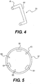
- FIG. 4 illustrates one possible configuration of strut 310.
- the strut has a central member 401 extending between a first strut leg 403 which pivotally engages a leg 309 and a second strut leg which pivotally engages the battery compartment 303.
- Other strut configuration may be used without departing from the scope of the invention.
- each leg When the legs 309 are collapsed, the exterior surface of each leg is substantially aligned with the exterior surface of lower collar portion 307, thereby forming a substantially cylindrical shape covering the main body 301 and battery compartment 303.
- Base 313 encloses battery compartment 303 forming a battery compartment lid at its bottom portion.
- base 303 has an outer diameter which approximates the outer diameter of the upper collar portion 305.
- a lip 315 formed by the exterior of the battery compartment 303 and base 313 can be entirely recessed or recessed in one or more locations so that when legs 309 are collapsed, they can be held in place by the recesses.
- an alternative is to hold legs 309 closed with a strap 105.
- collar 109 and main body 301 move relative to each other, so that the light can be deployed or placed in the collapsed position.
- Collar 109 has hand grips 320, which are openings in the upper collar portion 305. These opening serve as hand grips for use in collapsing the light.
- hand grips 320 which are openings in the upper collar portion 305. These opening serve as hand grips for use in collapsing the light.
- legs 309 lift from the surface on which they sit and move toward the battery compartment. This movement of the legs 309 toward the battery compartment drives the collar 109 upward relative to the main body 301.
- collar 109 moves downward relative to the main body, as the legs 309 move away from the battery compartment 303.
- main body 301 has slots 317 on its exterior surface 319. Slots 317 can be formed either as indentations in the exterior surface of the main body 301 or parallel protrusions from the exterior surface 319.
- At least one part of collar 109 has on its interior one or more guides 501.
- Guides 501 engage slots 317 in main body 301 and slide therein.
- Figure 5 also shows lower collar portion 307 having one or more other interior members 503 on its inner surface.
- Interior members 503 provide added strength to the collar portion.
- interior members 503 extend inward toward the main body 301, interior members 503 help to control lateral movement or wobbling between the main body 301 and the collar 109.
- Figure 6 is an exploded view of the elements of the exemplary embodiment of a collapsible light according to the invention as discussed herein.
- Figure 6 illustrates how the various elements previously discussed fit together.
- Figure 6 illustrates a battery pack 601 for insertion into battery compartment 303.
- Figure 6 also shows top cap 603 which mounts into the upper portion of main housing 301.
- Top cap 603 includes power switch 605.
- Power switch 605 can be a on-off switch or can be configured to cause lamp head 107 to emit multiple levels of illumination, for example, dim, medium and bright.
- Switch 605 can also be configured to turn on illuminating elements in the lamp head 107 in a desired sequence.
- Switch 605 can also be continuously variable, so that the light can be dimed.
- the switch can be any type suitable for turning on one or more lights, for example a rotary switch, without departing form the scope of the invention.
- top cap 603 and base 313 along with main body 301 and battery compartment 303 form a watertight enclosure which protects the elements within the main body, particularly during transport.
- the elements within this watertight enclosure include the battery, electrical circuits and switches, cables supplying electrical power to the lamp head and telescoping poles to which adjust the height of the lamp head.
- Such a watertight enclosure also helps facilitate flotation of the collapsible light according to the invention, should it fall into a liquid.
- Top cap 603 has opening 607 which accommodates one or more telescoping tubes.
- Figure 6 shows a fixed tube 609 with cam lock 610 and a telescoping tube 611 which fits within fixed tube 609.
- the cam lock 610 can be used to set the height of telescoping tube 611 to any desired position within the range of the length of the tubes. More than one telescoping tube and cam lock can be used without departing from the scope and spirit of the invention.
- Electrical power to the lamp head is typically delivered through a coiled cable (not shown) which fits within the tubes and extends to a length appropriate to size and number of telescoping tubes.
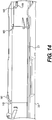
- Figure 7 is a transparent view of the portable light according to the invention, which illustrate the components of the portable light in the collapsed position for transport.
- Figure 7 also illustrate an otional protective feature which can be provided by collar 109.
- collar 109 and lamp head 107 are sized such that when the unit is collapsed and the telescoping members are retracted into each other, lamp head 107 fits within collar 109.
- collar 109 protects lamp head 107 from damage during transport.
- this feature is optional and lamp head 107 can be of any desired size.
- Figure 7 illustrates still another feature of a portable lamp according to the invention.
- a portable light according to the invention can be scalloped in at least one area 701 to facilitate carrying the unit on one's back, for example using should strap 103 as previously disclosed herein.
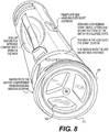
- Figure 8 illustrates a perspective view of a portable light according to the invention in a closed position.
- Figure 8 illustrates base 313, which forms a battery compartment lid, with a rim 801 to protect the battery compartment 303.
- the battery compartment lid provides access to change the batteries which power the lamp head. Connections between the battery and the cable to the lamp head (not shown) are internal to the battery compartment.
- the battery compartment can also have a charging socket 803, as shown in Fig. 8 .
- Charging circuitry is internal to the battery compartment and is not shown.
- Figure 9 is a more detailed illustration of the pivot connection between lower collar portion 307 and legs 309. As noted previously, a metal prong can be used to bias the legs outward toward the deployed position. Figure 9 shows another arrangement in which latch 901 is used to lock legs 309 into the deployed position.
- Figure 10 illustrates another approach to locking in the closed position.
- latch 1001 is used to latch the collar 109 to the legs 309 to maintain the collapsed position.
- Figure 10 also illustrates the cylindrical shape, resembling that of a karooka, of the portable light 101 according to the invention when in the collapsed position.
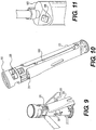
- FIG 11 is a more detailed illustration of switch 605 as located in main body top cap 603.
- Switch 605 can be equipped with a backlight, such as an LED, or other indicator to provide an indication of the current charge level.
- Figure 12 shows the lamp head 107 from the front, or illuminating side, as connected to an end of the telescoping pole 611. As illustrated in Figure 12 , lamp head 107 is connected to the telescoping pole using a connector 1201 which can pivot and/or rotate within the telescoping tube 611 to provide a wide range of motion.
- Figure 12 also shows light emitting diodes 1203 in the lamp head, which illuminate to provide light.
- the light emitting diodes could be replaced with or used in conjunction with halogen bulb, fluorescent bulb and/or incandescent bulbs. Any desired combination of such illuminating elements could be controlled by switch 605 to illuminate in any desired sequence, without departing from the scope of the invention.
- FIG. 13 shows lamp head 107 connected to telescoping tube 611 from the rear of the lamp head.
- pivoting connector 1201 is an offset hinge.
- Offset hinge 1202 includes a member 1301 which connects at a first end to the telescoping tube 611. Member 1301 can be arranged to rotate within tube 611, thereby allowing lamp head to be placed anywhere in a 360 range to direct light as desired.
- a second end of member 1301 pivotally connects to member 1302, which is connected to lamp head 107. By pivoting second member 1302 about point 1303, light from lamp head 107 can be directed vertically as desired.
- offset hinge 1201 permits about 135 degrees of movement of lamp head 107. Other arrangements which permit a wider or smaller range of motion may also be used.
- lamp 107 When the portable light according to the invention is to be placed in the collapsed position, lamp 107 is pulled toward the telescoping tube 611, such that member 1302 pivots about point 1303 to collapse member 1302 toward member 1301.
- lamp 107 When member 1302 is collapsed on member 1301, lamp 107 is positioned so that the illuminating elements therein face upward vertically. In this way, when the telescoping pole is lowered into the main body, the lamp head can be recessed into collar 109, so that collar 109 protects the lamp head.
- connection between the lamp head and the main body provides a wide range of motion, allowing the lamp head to be rotated to direct the light in a preferred direction and to be pointed upward or downward at an angle limited only by the physical dimensions of the lamp head and the connector. It will also be recognized that more than one pivoting connector can be used to direct light in any desired direction.
- Figure 14 shows a detail of a latch mechanism that can be used in a collapsible structure according to the invention.
- Figure 14 shows main body 301 and leg 309 in the collapsed position.
- To deploy one lifts the flexible latch 1401 located on battery compartment 303.
- Leg 309 deploys outward from the main body 301 until member 1402 aligns with groove.
- Lifing latch 1401 to disengage member 1402 from groove 1403 allows the structure to return to the collapsed position.
- hoop 1405 on the inside of the leg engages with a corresponding fork 1406, thereby eliminating the need for a leg strap to hold the legs in collapsed position.
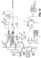
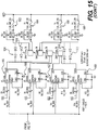
- FIG. 15 is an electrical schematic of a collapsible light according to the invention.
- Microcontroller 1501 such as MSP430F2002IPW, provides general control and operation to control LED drivers 1503, 1505, 1507 and 1509, for example, CAT 4101. These regulate the current to (drive) LEDs 1510 and 1512, 1514 and 1516.
- LEDS 1510, 1512, 1514 and 1516 receive power from fuse/resistor circuits 1502, 1504, 1506 and 1508.
- Voltage regulator 1511 provides voltage regulation from battery 1513. Battery 1513 may be recharged through charging connector 1515 and charging circuit 1519.
- Microcontroller 1501 is programmed to perform its functions through programming connector 1517.
- the above description for a portable light is illustrative, as the structure of the invention may be used in conjunction with other devices. It will be recognized that the light may be replaced by other operational units performing other functions. For example, the light may be replaced by a speaker to broadcast sound, a device which provides heat, a fan, a sensor to measure contaminants or air quality or any other number of devices.
- the device connected to the telescoping member need not be powered.
- the light in the description above may be replaced by a reflector or a solar powered device which generates its own power.
- the battery compartment can remain empty.
- the device connected to the end of the telescoping member may be one which generates electrical power, such as a windmill or solar collector. In that case, the battery compartment discussed above may be used to house energy storage devices.
- An embodiment of the invention may relate to a collapsible lighting device comprising:
- Said collapsible structure may comprise one or more of the following features:
Landscapes
- Engineering & Computer Science (AREA)
- General Engineering & Computer Science (AREA)
- Mechanical Engineering (AREA)
- Non-Portable Lighting Devices Or Systems Thereof (AREA)
- Arrangement Of Elements, Cooling, Sealing, Or The Like Of Lighting Devices (AREA)
Description
- The Invention relates to collapsible structures, in particular a collapsible lighting device followint the features of
claim 1, which can be transported to provide lighting in in areas where flashlights are unsatisfactory. - Flashlights have been used extensively in areas where lighting is not available. In many circumstances, however, flashlights are inadequate because they fail to provide adequate lighting to accommodate the needs of workers, campers, or persons engaged in other activities. Portable lights which stand alone provide necessary levels of light while leaving workers and other individuals free hands to perform tasks and conduct other activities. Representative examples of such lights are known from patent documents
US2005/117340 A1 ,BE458242A US2006/209547A1 orDE 29520042 . - Portable lights, however, tend to be bulky and large and inconvenient to carry. The invention disclosed herein provides a collapsible light in a form factor which is portable and easy to carry to provide light for many applications.
-
-
Figure 1 shows a collapsible light according to the invention in a collapsed position for transport; -
Figure 2 illustrates a collapsible light in a collapsed position as it might be carried on a back of a person; -
Figure 3 shows a collapsible light according to the invention in a fully deployed position; -
Figure 4 shows a strut in an assembly for use in a collapsible light according to the invention; -
Figure 5 shows a portion of a collar assembly in a collapsible light according to the invention; -
Figure 6 shows an exploded view of the elements of the light according to the invention; -
Figure 7 shows a transparent view of a light according to the invention in the collapsed position to illustrate its internal configuration; -
Figure 8 shows a bottom perspective view of a light according to the invention in a collapsed position; -
Figure 9 shows the collar, base and legs of an assembly according to the invention; -
Figure 10 is a side view of a light according to the invention in a collapsed position; -
Figure 11 illustrates the position of a multifunction power switch in a light according to the invention; -
Figure 12 illustrates a lamp head in a light according to the invention from a front perspective position; and -
Figure 13 illustrates a lamp head in a light according to the invention from a rear perspective position. -
Figure 14 illustrates a latching mechanism for use in a collapsible structure according to the invention. -
Figure 15 is an electrical schematic of a collapsible light according to the invention. -
Figure 1 shows acollapsible light 101 according to the invention in a substantially cylindrical form factor, resembling a bazooka, for easy transport.Collapsible light 101 has attached to it a carrying strap, 103, to facilitate carrying the bazooka shaped collapsible light on one's back, as illustrated inFigure 2 .Figure 1 further shows securingstrap 105. Securingstrap 105 can be used as one way to secure the legs, as discussed further herein, to form an exterior portion of the cylindrical shape in the collapsed position. Other means for securing the legs in the collapsed position can also be used.Figure 1 further illustrateslamp head 107, which has sockets therein for illuminating elements. As shown inFigure 1 ,lamp head 107 is tucked into acollar 109 to protect the lamp head when the light is in the collapsed position. -
Figure 3 illustrates an embodiment of a collapsible light according to the invention in the deployed position. As shown inFigure 3 , the structure of a collapsible light according to the invention includes amain body 301 which mounts on top of a lower body serving as abattery compartment 303 to form a substantially cylindrical shape. The main body and battery compartment can be formed separately or as an integrated unit. Other shapes, such as triangular, square, oval and rectangular, may also be employed without departing from the scope of the invention. - The invention also is not limited to any particular battery type. For example, the battery can be rechargeable or non-rechargeable. Battery charging circuitry and a suitable plug to an external power source may be incorporated into the lower
body battery compartment 303, or elsewhere in the light, as may be convenient. It is within the scope of the invention to provide illumination using an AC power source and/or one or more transformers. - The interior of
main body 301 can house electrical cables, such as a coiled electrical cable (not shown), to deliver electrical power to one or more illuminating elements, such as light emitting diodes, in thelamp head 107. Other types of illuminating elements, such as incandescent, halogen or fluorescent light elements, may be used inlamp head 107, without departing from the scope and spirit of the invention. As discussed further herein, themain body 301 also accommodates one or more telescoping members, which allow thelamp head 107 of the collapsible light according to the invention to be set at different heights to provide light over different size areas. - The
main body 301 is surrounded bycollar 109. In the exemplary configuration shown inFig. 3 ,collar 109 is a two part hollow cylindrical member, includingupper collar portion 305 andlower collar portion 307. The upper and lower collar portions, 305 and 307, may be formed separately and connected together or may be formed as an integrated unit.Upper collar portion 305 has a wider outer diameter thanlower collar portion 307. - One or
more legs 309 are pivotally attached or hinged tolower collar portion 307 atpivot points 311. The legs preferably have a curved shape, such that when the portable light according to the invention is in the collapsed position, the legs form a cylindrical exterior surface which approximates the exterior surface of theupper collar portion 305. - Optional metal prongs 312 on the interior surface of
legs 309 exert a springforce biasing legs 309 outward from thelower collar portion 307 into the deployed position.Struts 310 control the outward extension oflegs 309.Struts 310 are pivotally connected to the lower portion of the central section of the collapsible light, for example tobattery compartment 303, and pivotally connected to the interior portion oflegs 309.Struts 310 act to control the legs as they deploy away from the outer surface of thelower collar portion 307, limit the distance thelegs 309 deploy and provide stability when thelegs 309 are fully deployed. Those of ordinary skill will recognize thatstruts 310 could be connected at different locations on the interior surface of the legs and on the central section of the collapsible light to achieve different relationships between thelegs 309 and the central section of the collapsible light as desired. For example, thestruts 310 could be positioned and sized such that thebase 313 touches the ground or other surface beneath the base when the collapsible light is deployed. Alternatively,struts 310 could be positioned and sized to insure that thebase 313 does not touch the ground or other surface beneath the base when the collapsible light according to the invention is deployed. -
Figure 4 illustrates one possible configuration ofstrut 310. The strut has acentral member 401 extending between a first strut leg 403 which pivotally engages aleg 309 and a second strut leg which pivotally engages thebattery compartment 303. Other strut configuration may be used without departing from the scope of the invention. - When the
legs 309 are collapsed, the exterior surface of each leg is substantially aligned with the exterior surface oflower collar portion 307, thereby forming a substantially cylindrical shape covering themain body 301 andbattery compartment 303.Base 313 enclosesbattery compartment 303 forming a battery compartment lid at its bottom portion. As shown inFigure 3 ,base 303 has an outer diameter which approximates the outer diameter of theupper collar portion 305. In one exemplary configuration, alip 315 formed by the exterior of thebattery compartment 303 andbase 313 can be entirely recessed or recessed in one or more locations so that whenlegs 309 are collapsed, they can be held in place by the recesses. As noted above, however, an alternative is to holdlegs 309 closed with astrap 105. - In operation,
collar 109 andmain body 301 move relative to each other, so that the light can be deployed or placed in the collapsed position.Collar 109 has hand grips 320, which are openings in theupper collar portion 305. These opening serve as hand grips for use in collapsing the light. When the collapsible light is deployed and thecollar 109 is lifted usinghand grips 320,legs 309 lift from the surface on which they sit and move toward the battery compartment. This movement of thelegs 309 toward the battery compartment drives thecollar 109 upward relative to themain body 301. When the portable light is deployed from the closed position,collar 109 moves downward relative to the main body, as thelegs 309 move away from thebattery compartment 303. - In order to facilitate and control the movement between the
main body 301 and thecollar 109,main body 301 hasslots 317 on itsexterior surface 319.Slots 317 can be formed either as indentations in the exterior surface of themain body 301 or parallel protrusions from theexterior surface 319. - As shown in
Figure 5 , at least one part ofcollar 109, such aslower collar portion 307, has on its interior one or more guides 501.Guides 501 engageslots 317 inmain body 301 and slide therein.Figure 5 also showslower collar portion 307 having one or more otherinterior members 503 on its inner surface.Interior members 503 provide added strength to the collar portion. In addition, becauseinterior members 503 extend inward toward themain body 301,interior members 503 help to control lateral movement or wobbling between themain body 301 and thecollar 109. -
Figure 6 is an exploded view of the elements of the exemplary embodiment of a collapsible light according to the invention as discussed herein.Figure 6 illustrates how the various elements previously discussed fit together. In addition,Figure 6 illustrates abattery pack 601 for insertion intobattery compartment 303.Figure 6 also showstop cap 603 which mounts into the upper portion ofmain housing 301.Top cap 603 includespower switch 605.Power switch 605 can be a on-off switch or can be configured to causelamp head 107 to emit multiple levels of illumination, for example, dim, medium and bright. Switch 605 can also be configured to turn on illuminating elements in thelamp head 107 in a desired sequence. Switch 605 can also be continuously variable, so that the light can be dimed. The switch can be any type suitable for turning on one or more lights, for example a rotary switch, without departing form the scope of the invention. - Preferably,
top cap 603 andbase 313 along withmain body 301 andbattery compartment 303 form a watertight enclosure which protects the elements within the main body, particularly during transport. The elements within this watertight enclosure include the battery, electrical circuits and switches, cables supplying electrical power to the lamp head and telescoping poles to which adjust the height of the lamp head. Such a watertight enclosure also helps facilitate flotation of the collapsible light according to the invention, should it fall into a liquid. -
Top cap 603 has opening 607 which accommodates one or more telescoping tubes.Figure 6 shows a fixedtube 609 withcam lock 610 and atelescoping tube 611 which fits within fixedtube 609. Thecam lock 610 can be used to set the height oftelescoping tube 611 to any desired position within the range of the length of the tubes. More than one telescoping tube and cam lock can be used without departing from the scope and spirit of the invention. Electrical power to the lamp head is typically delivered through a coiled cable (not shown) which fits within the tubes and extends to a length appropriate to size and number of telescoping tubes. -
Figure 7 is a transparent view of the portable light according to the invention, which illustrate the components of the portable light in the collapsed position for transport.Figure 7 also illustrate an otional protective feature which can be provided bycollar 109. As shown inFigure 7 ,collar 109 andlamp head 107 are sized such that when the unit is collapsed and the telescoping members are retracted into each other,lamp head 107 fits withincollar 109. Thus, when sized thisway collar 109 protectslamp head 107 from damage during transport. As noted, however, this feature is optional andlamp head 107 can be of any desired size.Figure 7 illustrates still another feature of a portable lamp according to the invention. As shown inFigure 7 , a portable light according to the invention can be scalloped in at least onearea 701 to facilitate carrying the unit on one's back, for example using should strap 103 as previously disclosed herein. -
Figure 8 illustrates a perspective view of a portable light according to the invention in a closed position.Figure 8 illustratesbase 313, which forms a battery compartment lid, with arim 801 to protect thebattery compartment 303. The battery compartment lid provides access to change the batteries which power the lamp head. Connections between the battery and the cable to the lamp head (not shown) are internal to the battery compartment. The battery compartment can also have a chargingsocket 803, as shown inFig. 8 . Charging circuitry is internal to the battery compartment and is not shown. -
Figure 9 is a more detailed illustration of the pivot connection betweenlower collar portion 307 andlegs 309. As noted previously, a metal prong can be used to bias the legs outward toward the deployed position.Figure 9 shows another arrangement in which latch 901 is used to locklegs 309 into the deployed position. - The side view in
Figure 10 illustrates another approach to locking in the closed position. InFigure 10 latch 1001 is used to latch thecollar 109 to thelegs 309 to maintain the collapsed position.Figure 10 also illustrates the cylindrical shape, resembling that of a bazooka, of theportable light 101 according to the invention when in the collapsed position. -
Figure 11 is a more detailed illustration ofswitch 605 as located in mainbody top cap 603. Switch 605 can be equipped with a backlight, such as an LED, or other indicator to provide an indication of the current charge level. -
Figure 12 shows thelamp head 107 from the front, or illuminating side, as connected to an end of thetelescoping pole 611. As illustrated inFigure 12 ,lamp head 107 is connected to the telescoping pole using aconnector 1201 which can pivot and/or rotate within thetelescoping tube 611 to provide a wide range of motion.Figure 12 also showslight emitting diodes 1203 in the lamp head, which illuminate to provide light. One or more other types of illuminating members could also be used. For example, the light emitting diodes could be replaced with or used in conjunction with halogen bulb, fluorescent bulb and/or incandescent bulbs. Any desired combination of such illuminating elements could be controlled byswitch 605 to illuminate in any desired sequence, without departing from the scope of the invention. -
Figure 13 showslamp head 107 connected totelescoping tube 611 from the rear of the lamp head. As shown inFigure 13 , when pivotingconnector 1201 is an offset hinge. Offset hinge 1202 includes amember 1301 which connects at a first end to thetelescoping tube 611.Member 1301 can be arranged to rotate withintube 611, thereby allowing lamp head to be placed anywhere in a 360 range to direct light as desired. A second end ofmember 1301 pivotally connects tomember 1302, which is connected tolamp head 107. By pivotingsecond member 1302 aboutpoint 1303, light fromlamp head 107 can be directed vertically as desired. As shown, offsethinge 1201 permits about 135 degrees of movement oflamp head 107. Other arrangements which permit a wider or smaller range of motion may also be used. When the portable light according to the invention is to be placed in the collapsed position,lamp 107 is pulled toward thetelescoping tube 611, such thatmember 1302 pivots aboutpoint 1303 to collapsemember 1302 towardmember 1301. Whenmember 1302 is collapsed onmember 1301,lamp 107 is positioned so that the illuminating elements therein face upward vertically. In this way, when the telescoping pole is lowered into the main body, the lamp head can be recessed intocollar 109, so thatcollar 109 protects the lamp head. As illustrated inFigure 12 , when deployed, the connection between the lamp head and the main body provides a wide range of motion, allowing the lamp head to be rotated to direct the light in a preferred direction and to be pointed upward or downward at an angle limited only by the physical dimensions of the lamp head and the connector. It will also be recognized that more than one pivoting connector can be used to direct light in any desired direction. -
Figure 14 shows a detail of a latch mechanism that can be used in a collapsible structure according to the invention.Figure 14 showsmain body 301 andleg 309 in the collapsed position. To deploy, one lifts theflexible latch 1401 located onbattery compartment 303.Leg 309 deploys outward from themain body 301 untilmember 1402 aligns with groove.Lifing latch 1401 to disengagemember 1402 fromgroove 1403 allows the structure to return to the collapsed position. In this position,hoop 1405 on the inside of the leg engages with acorresponding fork 1406, thereby eliminating the need for a leg strap to hold the legs in collapsed position. -
Figure 15 is an electrical schematic of a collapsible light according to the invention. Those of ordinary skill will recognize that the circuits implement the features previously discussed herein.Microcontroller 1501, such as MSP430F2002IPW, provides general control and operation to controlLED drivers LEDs LEDS resistor circuits Voltage regulator 1511 provides voltage regulation frombattery 1513.Battery 1513 may be recharged through chargingconnector 1515 and chargingcircuit 1519.Microcontroller 1501 is programmed to perform its functions throughprogramming connector 1517. - The above description for a portable light is illustrative, as the structure of the invention may be used in conjunction with other devices. It will be recognized that the light may be replaced by other operational units performing other functions. For example, the light may be replaced by a speaker to broadcast sound, a device which provides heat, a fan, a sensor to measure contaminants or air quality or any other number of devices. Indeed, the device connected to the telescoping member need not be powered. For example, the light in the description above may be replaced by a reflector or a solar powered device which generates its own power. In the case of an device which does not require power, the battery compartment can remain empty. In still another application, the device connected to the end of the telescoping member may be one which generates electrical power, such as a windmill or solar collector. In that case, the battery compartment discussed above may be used to house energy storage devices.
- In summary:
An embodiment of the invention may relate to a collapsible lighting device comprising: - (a) a main body:
- (b) a telescoping member adjustable to a position within said main body;
- (c) a lamp head positioned at a first end of said telescoping member, said lamp head having sockets for illuminating elements:
- (d) an electrical connection to provide a connection between said lamp head and a power source; and
- (e) a collar surrounding said main body, said collar being adjustable to a first collar position relative to said main body when said portable lighting device is in a deployed position, and to a second collar position relative to said main body when said collapsible lighting device is in a collapsed position.
- The collapsible lighting device may comprise a leg pivotally connected to said collar and to said main body to support said portable light in said deployed position.
- Said collar may adjust to said first collar position when said leg is in a first leg position to support said lighting device in a deployed position. Said collar may adjust to said collar second position when said leg is in a second leg position.
- Said collar may have hand grips therein, said hand grips allowing adjustment of said collar to said first collar position and said second collar position.
- Said collar may have an opening wider than a diameter of said main body.
- According to the invention, said collar is adjustable to a position to enclose exterior side surfaces of said lamp head when said lighting device is in a collapsed position.
- The collapsible lighting device may comprise a pivoting connection between said lamp head and said telescoping member.
- Said pivoting connection between said lamp head and said telescoping member may comprise a hinge joint.
- Said lamp head may comprise a plurality of illuminating elements.
- Said illuminating elements may comprise at least one of a light emitting diode, an incandescent bulb, a fluorescent bulb and a halogen bulb.
- The collapsible lighting device may comprise a switch, said switch activating at least one of said illuminating elements.
- Said switch may activate each of said illuminating elements in a sequence.
- Said switch may comprise a continuously variable switch.
- Said switch may comprise an indicator to indicate a state of power available from said power source.
- Said power source may comprise a battery.
- Said battery may comprise a rechargeable battery.
- The collapsible lighting device may comprise battery recharging circuits.
- Said collapsible lighting device may collapse to a substantially cylindrical shape.
- The collapsible lighting device may comprise a should strap for carrying said collapsible lighting device when in said collapsed position.
- A further embodiment of the invention may relate to a lighting device comprising:
- (a) a main body;
- (b) a lamp head having sockets therein for illuminating elements;
- (c) an electrical connection to provide a connection between a power source and said lamp head;
- (d) a collar surrounding said main body, said collar being moveable relative to said main body;
- (e) a plurality of legs adjustably connected to said collar, said legs supporting said lighting device in an upright position, said position of said legs determining said position of said collar.
- A further embodiment of the invention may relate to a collapsible structure comprising:
- (a) a main body;
- (b) a telescoping member adjustable to a position within said main body;
- (c) an operational unit positioned at a first end of said telescoping member;
- (d) a collar surrounding said main body, said collar being adjustable to a first collar position relative to said main body when said collapsible structure is in a deployed position and to a second collar position relative to said main body when said collapsible structure is in a collapsed position.
- Said collapsible structure may comprise one or more of the following features:
- The collapsible structure may comprise a leg pivotally connected to said collar and to said main body to support said collapsible device in said deployed position.
- Said collar may adjust to said first collar position when said leg is in a first leg position to support said lighting device in a deployed position, and said collar may adjust to said collar second position when said leg is in a second leg position.
- Said collar may have hand grips therein, said hand grips allowing adjustment of said collar to said first collar position and said second collar position.
- Said collar may have an opening wider than a diameter of said main body.
- Said collar may be adjustable to a position to enclose exterior side surfaces of said operational unit when said collapsible structure is in a collapsed position.
- The collapsible structure may comprise a pivoting connection between said operational unit and said telescoping member.
- Said pivoting connection between said lamp head and said telescoping member may comprise a hinge joint.
- A further embodiment of the invention may relate to a collapsible structure comprising
- (a) a main body;
- (b) an operational unit;
- (c) an electrical connection to provide a connection between a power source and said operational unit;
- (d) a collar surrounding said main body, said collar being moveable relative to said main body;
- (e) a plurality of legs adjustably connected to said collar, said legs supporting said operational unit in an upright position, said position of said legs determining said position of said collar.
Claims (12)
- A collapsible lighting device comprising:(a) a main body (301);(b) a telescoping member adjustable to a position within said main body;(c) a lamp head (107) positioned at a first end of said telescoping member, said lamp head having sockets for illuminating elements:(d) an electrical connection to provide a connection between said lamp head and a power source; and(e) a collar (109) surrounding said main body, said collar being adjustable to a first collar position relative to said main body when said portable lighting device is in a deployed position, and to a second collar position relative to said main body wherein said collar is adjustable to a position to substantially enclose exterior side surfaces of said lamp head when said collapsible lighting device is in a collapsed position.
- The collapsible lighting device recited in claim 1 further comprising:(a) a leg (309) pivotally connected to said collar and to said main body to support said portable light in said deployed position.
- The collapsible lighting device recited in claim 2, wherein said collar adjusts to said first collar position when said leg is in a first leg position to support said lighting device in a deployed position and said collar adjusts to said collar second position when said leg is in a second leg position.
- The collapsible lighting device recited in claim 3, said collar having hand grips (320) therein, said hand grips allowing adjustment of said collar to said first collar position and said second collar position.
- The collapsible lighting device recited in claim 4, said collar having an opening wider than a diameter of said main body.
- The collapsible lighting device recited in claim 5, wherein said collapsible lighting device collapses to a substantially cylindrical shape.
- The collapsible lighting device recited in claim 5, comprising a pivoting connection between said lamp head and said telescoping member.
- The collapsible lighting device recited in claim 7, wherein said pivoting connection between said lamp head and said telescoping member comprises a hinge joint.
- The collapsible lighting device recited in claim 8, said lamp head comprising a plurality of illuminating elements.
- The collapsible lighting device recited in claim 1, comprising a switch, said switch activating at least one of said illuminating elements.
- The collapsible lighting device recited in claim 10, said switch further comprising an indicator to indicate a state of power available from said power source.
- The collapsible lighting device recited in claim 1, said power source comprising a battery (601, 1513), a rechargeable battery and/or battery recharging circuits.
Applications Claiming Priority (1)
| Application Number | Priority Date | Filing Date | Title |
|---|---|---|---|
| US12/591,487 US8201979B2 (en) | 2009-11-20 | 2009-11-20 | Collapsible light |
Publications (2)
| Publication Number | Publication Date |
|---|---|
| EP2325552A1 EP2325552A1 (en) | 2011-05-25 |
| EP2325552B1 true EP2325552B1 (en) | 2017-04-05 |
Family
ID=43533570
Family Applications (1)
| Application Number | Title | Priority Date | Filing Date |
|---|---|---|---|
| EP10075729.3A Active EP2325552B1 (en) | 2009-11-20 | 2010-11-05 | Collapsible light |
Country Status (7)
| Country | Link |
|---|---|
| US (3) | US8201979B2 (en) |
| EP (1) | EP2325552B1 (en) |
| JP (1) | JP5707104B2 (en) |
| CN (2) | CN102072411B (en) |
| AU (1) | AU2010246335B2 (en) |
| CA (1) | CA2719151C (en) |
| ES (1) | ES2632176T3 (en) |
Families Citing this family (64)
| Publication number | Priority date | Publication date | Assignee | Title |
|---|---|---|---|---|
| US8201979B2 (en) | 2009-11-20 | 2012-06-19 | Pelican Products, Inc. | Collapsible light |
| US20120113629A1 (en) * | 2010-09-17 | 2012-05-10 | Diane Michelle Steele | Outdoor solar Tiki floor lamp |
| US8662720B2 (en) * | 2011-05-20 | 2014-03-04 | Luther CIFERS | Fold-up beacon and associated post for vehicles |
| CN102954448B (en) * | 2011-10-29 | 2016-01-06 | 诸法 | lamp supporting device |
| US20130265780A1 (en) * | 2012-04-05 | 2013-10-10 | Black & Decker Inc. | Light module and light stand assembly |
| US9114752B2 (en) | 2012-10-28 | 2015-08-25 | Measurement Ltd. | Automotive safety device |
| EP2912373A4 (en) * | 2012-10-28 | 2017-01-11 | Measurement Ltd. | Automotive safety device |
| US9243787B2 (en) | 2012-10-28 | 2016-01-26 | Measurement Ltd. | Automotive safety device |
| US9170006B2 (en) * | 2013-01-15 | 2015-10-27 | Foxfury Llc | Light fixture reconfigurable between area lighting and spot lighting configurations |
| DE102013002202A1 (en) * | 2013-02-07 | 2014-08-07 | Wacker Neuson Produktion GmbH & Co. KG | Portable lighting device |
| KR20150141953A (en) * | 2013-03-12 | 2015-12-21 | 인터내셔널 디벨롭먼트 엘엘씨 | Collapsible worklight assembly |
| US9222633B2 (en) | 2013-04-09 | 2015-12-29 | Mathew Inskeep | Multi-axis tilting light stand with removable light |
| WO2015061439A1 (en) * | 2013-10-22 | 2015-04-30 | Studio Weber + Associates | Multifunctional power supply device |
| WO2015105983A1 (en) * | 2014-01-09 | 2015-07-16 | Streamlight, Inc. | Portable lantern and scene light |
| FR3016513B1 (en) * | 2014-01-17 | 2016-03-25 | Samuel Andre Mercier | EXTRA-HOSPITAL MEDICAL WORKS STATION |
| US9380904B2 (en) * | 2014-06-18 | 2016-07-05 | Shane E. PEEK | Telescoping compass device |
| CN104111574B (en) * | 2014-07-29 | 2016-09-07 | 常熟市筑紫机械有限公司 | The camera flash lamp support that structure is improved |
| CN104111575B (en) * | 2014-07-29 | 2016-09-07 | 常熟市筑紫机械有限公司 | Camera flash-light supporting structure |
| US9298066B1 (en) * | 2014-10-28 | 2016-03-29 | Eagle Fan | Multi-functional support assembly |
| NZ734170A (en) | 2015-02-04 | 2019-05-31 | Milwaukee Electric Tool Corp | Light including a heat sink and leds coupled to the heat sink |
| US9810408B2 (en) * | 2015-04-09 | 2017-11-07 | Ningbo Utec Electric Co., Ltd. | Portable lighting apparatus |
| US10094544B2 (en) * | 2015-04-09 | 2018-10-09 | Ningbo Utec Electric Co., Ltd. | Portable lighting apparatus |
| US10378739B2 (en) * | 2015-04-24 | 2019-08-13 | Milwaukee Electric Tool Corporation | Stand light |
| US9489841B1 (en) | 2015-06-18 | 2016-11-08 | James Damian Huggins | Portable multi-function roadway barrier |
| US10775032B2 (en) | 2015-07-01 | 2020-09-15 | Milwaukee Electric Tool Corporation | Area light |
| US20170003574A1 (en) * | 2015-07-02 | 2017-01-05 | Hanel CHOI | Systems and devices for modular portable lighting |
| CN105180064A (en) * | 2015-07-23 | 2015-12-23 | 中山市科贝照明科技有限公司 | Small foldable fan LED lamp |
| US11187388B2 (en) | 2015-07-31 | 2021-11-30 | Richpower Industries, Inc. | Lighting assembly |
| USD767807S1 (en) | 2015-07-31 | 2016-09-27 | Richpower Industries Inc. | Lighting assembly |
| CA2989044C (en) * | 2015-07-31 | 2023-07-11 | Richpower Industries, Inc. | Lighting assembly |
| US10323831B2 (en) | 2015-11-13 | 2019-06-18 | Milwaukee Electric Tool Corporation | Utility mount light |
| USD778338S1 (en) | 2015-12-15 | 2017-02-07 | Gopro, Inc. | Camera mount handle |
| CN105570752A (en) * | 2016-01-28 | 2016-05-11 | 成都绿迪科技有限公司 | Portable LED lamp |
| US10247400B2 (en) * | 2016-02-12 | 2019-04-02 | Kyle Thomas Cate | Safety light for law enforcement and road-side emergency |
| USD816252S1 (en) | 2016-05-16 | 2018-04-24 | Milwaukee Electric Tool Corporation | Light |
| USD841849S1 (en) | 2016-10-31 | 2019-02-26 | Delta T, Llc | Handheld light assembly with battery pack |
| EP3548797B1 (en) | 2016-11-23 | 2023-08-09 | Milwaukee Electric Tool Corporation | Area light |
| CN106641808A (en) * | 2016-11-23 | 2017-05-10 | 南京工业职业技术学院 | Flashlight capable of being extended to form table lamp |
| WO2019071159A1 (en) * | 2017-10-06 | 2019-04-11 | Milwaukee Electric Tool Corporation | Stand light |
| USD890982S1 (en) * | 2017-10-16 | 2020-07-21 | Daniel R. Vartan | Base for a light |
| AU201716309S (en) * | 2017-10-17 | 2017-11-06 | Qee Tech Shenzhen Co | New Multiple Purpose Light |
| CN107676645B (en) * | 2017-10-31 | 2020-09-15 | 商洛市虎之翼科技有限公司 | Flashlight using strap flexible connection structure |
| USD904830S1 (en) | 2017-12-14 | 2020-12-15 | Dometic Sweden Ab | Soft bag cooler |
| AU201717676S (en) | 2017-12-14 | 2018-01-16 | Dometic Sweden Ab | Zip Puller |
| JP1618305S (en) * | 2017-12-26 | 2018-11-19 | ||
| US11578860B2 (en) * | 2018-02-20 | 2023-02-14 | ZHUN-AN Ma | Stand for portable accessory |
| USD869718S1 (en) | 2018-02-20 | 2019-12-10 | ZHUN-AN Ma | Umbrella attached light |
| US11262020B2 (en) | 2018-08-02 | 2022-03-01 | Milwaukee Electric Tool Corporation | Standing tool with telescopic arm having a guide rod |
| CA3053026A1 (en) | 2018-09-07 | 2020-03-07 | Signalisation D'urgence Rh Inc. | Collapsible warning device and method for emitting a light signal |
| CN109442243A (en) * | 2018-11-08 | 2019-03-08 | 湖北工业大学 | A kind of Multi-function lighting device |
| US10575635B1 (en) * | 2018-11-16 | 2020-03-03 | Jaime Ward | Portable garment caddy |
| KR102276180B1 (en) * | 2019-04-15 | 2021-07-12 | 조성민 | Portable light |
| CN217109359U (en) | 2019-07-19 | 2022-08-02 | 米沃奇电动工具公司 | Floor lamp |
| USD1010203S1 (en) * | 2019-07-25 | 2024-01-02 | Milwaukee Electric Tool Corporation | Light stand |
| CN110296362B (en) * | 2019-07-25 | 2024-04-30 | 广东新佳盟电子科技有限公司 | Folding lamp |
| JP7323431B2 (en) * | 2019-11-07 | 2023-08-08 | 株式会社マキタ | portable light |
| USD1018956S1 (en) * | 2019-11-18 | 2024-03-19 | Milwaukee Electric Tool Corporation | Stand light |
| US20220069399A1 (en) | 2020-08-31 | 2022-03-03 | Techtronic Cordless Gp | Tripod system |
| USD986461S1 (en) * | 2021-01-26 | 2023-05-16 | Ningbo UTEC Electric Co. Ltd. | Work light |
| EP4239245A4 (en) * | 2022-01-19 | 2024-04-10 | Shenzhen Habitat Tech Co Ltd | Lighting device |
| CN218153933U (en) * | 2022-06-01 | 2022-12-27 | 深圳市栖息科技有限公司 | Base assembly and lighting device |
| CN116293558A (en) * | 2023-02-16 | 2023-06-23 | 深圳市尚为市政智能照明有限公司 | Liftable support and contain its emergency work lamp |
| CN116480995A (en) * | 2023-04-21 | 2023-07-25 | 重庆欧偌医疗科技有限公司 | Portable operation lighting lamp |
| USD1005377S1 (en) * | 2023-06-26 | 2023-11-21 | Shenzhen Neewer Technology Co. Ltd | Photography tripod |
Family Cites Families (66)
| Publication number | Priority date | Publication date | Assignee | Title |
|---|---|---|---|---|
| BE458242A (en) | ||||
| US3026409A (en) * | 1958-08-21 | 1962-03-20 | Deisch Noel | Photographic illuminating equipment |
| US3064932A (en) * | 1960-07-01 | 1962-11-20 | Jim D Holderman | Adjustable stand for cameras, lights and the like |
| US3697031A (en) * | 1970-12-14 | 1972-10-10 | Berkey Colortran | Extensible leg structure for tripod or the like |
| GB1473888A (en) * | 1973-07-30 | 1977-05-18 | Australia Department Of Ind An | Portable high intensity lamp |
| JPS5537833Y2 (en) * | 1976-04-13 | 1980-09-04 | ||
| JPS52137129A (en) | 1976-05-12 | 1977-11-16 | Yamazaki Keiichiro | Handrail |
| US4974134A (en) * | 1989-11-29 | 1990-11-27 | Bourne Steven M | Illumination device having underground storage position |
| USD335889S (en) * | 1990-08-24 | 1993-05-25 | Kahlil Gibran | Tripod |
| US5122781A (en) * | 1990-09-06 | 1992-06-16 | Bolan Trading Inc. | Hazard warning light |
| US5068773A (en) * | 1991-03-13 | 1991-11-26 | Aqua-Lawn, Inc. | Retractable low voltage lighting fixture |
| US5075834A (en) * | 1991-03-25 | 1991-12-24 | Puglisi Daniel G | Retractable light fixture |
| US5060894A (en) * | 1991-04-22 | 1991-10-29 | Alltrade, Inc. | Stand with collapsible legs |
| JPH0618797U (en) * | 1992-02-12 | 1994-03-11 | 敏一 大松 | Tripod for camera |
| US5513085A (en) * | 1993-01-28 | 1996-04-30 | Bourne; Steven M. | Retractable light and motion detector |
| US5345305A (en) * | 1993-04-22 | 1994-09-06 | Chen Chi Der | Aquarium light meter |
| US5424928A (en) * | 1993-06-10 | 1995-06-13 | Northern Lights, Inc. | Lantern |
| US5319365A (en) * | 1993-09-23 | 1994-06-07 | Alltrade Inc. | Portable hazard-warning light assembly |
| US5513805A (en) * | 1995-03-31 | 1996-05-07 | Fisher; Gordon L. | Fiber separation method and apparatus |
| US5684452A (en) * | 1995-06-12 | 1997-11-04 | Wang; Shiunn-Terny | Multi-purposes warning device |
| DE29520042U1 (en) | 1995-12-18 | 1996-02-15 | Braun Andreas | Tripod for headlights or the like |
| US5630660A (en) * | 1996-05-16 | 1997-05-20 | Chen; Wei-Fu | Warning light |
| US5934628A (en) * | 1997-01-23 | 1999-08-10 | Bosnakovic; Frederick | Portable vertical support |
| GB2330679B (en) * | 1997-10-21 | 2002-04-24 | 911 Emergency Products Inc | Warning signal light |
| US5964524A (en) * | 1998-01-22 | 1999-10-12 | Regent Lighting Corporation | Worklight with stand |
| US6371625B2 (en) * | 1998-11-23 | 2002-04-16 | James P. Campman | All solid-state omni directional luminary and flashlight |
| US6702452B2 (en) * | 1999-11-15 | 2004-03-09 | Xenonics, Inc. | Apparatus and method for operating a portable xenon arc searchlight |
| CA2296859A1 (en) * | 2000-01-21 | 2001-07-21 | Hung-Ming Shih | Warning device for motor vehicle |
| GB0029254D0 (en) | 2000-11-30 | 2001-01-17 | Wolfe Designs Ltd | Retractable towers |
| US6438889B1 (en) * | 2001-02-09 | 2002-08-27 | Thomas A. Handy | Fishing rod support apparatus |
| US7083298B2 (en) * | 2001-10-03 | 2006-08-01 | Led Pipe | Solid state light source |
| JP4110775B2 (en) * | 2001-11-14 | 2008-07-02 | 光二 三橋 | Work light fixture for stand type vehicles |
| US6682209B2 (en) * | 2001-11-30 | 2004-01-27 | Cooper Technologies Company | Integral worklight |
| US6625918B2 (en) * | 2001-12-03 | 2003-09-30 | Tarseam S. Bhullar | Pest deterrent |
| DE20200634U1 (en) | 2002-01-16 | 2002-05-23 | Dullin Rainer D | Portable rechargeable worklight |
| US6637904B2 (en) * | 2002-02-25 | 2003-10-28 | Refugio E. Hernandez | Wireless quick release lighting system with supports, mounting brackets, lights, and accessories |
| US20040011930A1 (en) * | 2002-07-19 | 2004-01-22 | Tuohy Dennis J. | Bucket support device |
| US6854861B2 (en) * | 2002-11-21 | 2005-02-15 | Miao Li Chao | Telescopic universal flashlight |
| US6873249B2 (en) * | 2002-12-31 | 2005-03-29 | Wu-Lung Chu | Luminous alarm device |
| US8281737B2 (en) * | 2003-03-10 | 2012-10-09 | Boston Scientific Scimed, Inc. | Coated medical device and method for manufacturing the same |
| US7042184B2 (en) * | 2003-07-08 | 2006-05-09 | Board Of Regents Of The University Of Nebraska | Microrobot for surgical applications |
| US6899441B2 (en) * | 2003-08-04 | 2005-05-31 | Hsiu Chin Chen | Multifunction warning device |
| US7011423B2 (en) * | 2003-08-04 | 2006-03-14 | Hsiu Chin Chen | Multifunction warning device |
| AU2004226925A1 (en) * | 2003-11-03 | 2005-05-19 | Black & Decker, Inc. | Tripod assembly |
| USD508938S1 (en) * | 2003-11-07 | 2005-08-30 | Black & Decker Inc. | Tripod |
| USD505442S1 (en) * | 2003-11-07 | 2005-05-24 | Black & Decker Inc. | Folding laser tripod |
| CN1661272A (en) * | 2004-02-17 | 2005-08-31 | Eml技术有限责任公司 | Omni-directional worklight |
| CA2499137C (en) * | 2004-03-01 | 2012-07-17 | Lee W. Rempel | Box light |
| TWM264427U (en) * | 2004-06-24 | 2005-05-11 | Shiun-Teng Wang | Illuminant alarm device with a directing function |
| USD514009S1 (en) * | 2004-06-29 | 2006-01-31 | Parr Ben C | Safety triangle |
| US20060012487A1 (en) * | 2004-07-16 | 2006-01-19 | Gibson Thomas W | Traffic control sign assembly |
| US7342360B2 (en) * | 2004-10-20 | 2008-03-11 | The Stanley Works | Flashlight |
| US20060209547A1 (en) * | 2005-03-15 | 2006-09-21 | John Biondo | Rapid dispatch emergency signs |
| US7195377B2 (en) * | 2005-06-09 | 2007-03-27 | Peter Tsai | Worklight support with stand |
| TWM281251U (en) * | 2005-07-25 | 2005-11-21 | Jeng-Shi Chen | Command baton capable of being used as police baton and illumination flashlight |
| US20070158509A1 (en) * | 2006-01-06 | 2007-07-12 | Shannon Richard Hubbell | Pool cue case of musicians instrument case with tripod stand and rest |
| US7484858B2 (en) * | 2007-03-28 | 2009-02-03 | Pelican Products, Inc. | Lighting system |
| USD562715S1 (en) * | 2007-06-22 | 2008-02-26 | Treloar John C | Vehicle safety light with tripod and suction cup |
| US20090103290A1 (en) * | 2007-10-19 | 2009-04-23 | Kou-Ling Liu | Telescopic and bendable electric torch |
| CN201133576Y (en) * | 2007-12-29 | 2008-10-15 | 朱朝才 | Folding type multipurpose lamp |
| US8087797B2 (en) * | 2008-07-18 | 2012-01-03 | Stanley Black & Decker, Inc. | Illumination device with detachable light sources |
| US20100053944A1 (en) * | 2008-09-01 | 2010-03-04 | Cho Yao-Lin | Telescopic flashlight |
| US8142045B2 (en) * | 2009-05-04 | 2012-03-27 | Jason Peak | Utility light with articulating mounting legs adapted with suction cup fasteners |
| US8201979B2 (en) * | 2009-11-20 | 2012-06-19 | Pelican Products, Inc. | Collapsible light |
| US8262248B2 (en) * | 2009-12-24 | 2012-09-11 | Wessel Elmer A | Convertible work light |
| USD639986S1 (en) * | 2009-12-24 | 2011-06-14 | Wessel Elmer A | Convertible work light |
-
2009
- 2009-11-20 US US12/591,487 patent/US8201979B2/en active Active
-
2010
- 2010-10-28 CA CA2719151A patent/CA2719151C/en active Active
- 2010-11-05 ES ES10075729.3T patent/ES2632176T3/en active Active
- 2010-11-05 EP EP10075729.3A patent/EP2325552B1/en active Active
- 2010-11-16 CN CN201010551699.2A patent/CN102072411B/en active Active
- 2010-11-16 JP JP2010255567A patent/JP5707104B2/en not_active Expired - Fee Related
- 2010-11-16 CN CN201410347684.2A patent/CN104132255B/en active Active
- 2010-11-19 AU AU2010246335A patent/AU2010246335B2/en active Active
-
2012
- 2012-05-17 US US13/474,608 patent/US8651438B2/en active Active
-
2014
- 2014-02-16 US US14/181,703 patent/US9303853B2/en active Active
Non-Patent Citations (1)
| Title |
|---|
| None * |
Also Published As
| Publication number | Publication date |
|---|---|
| US20140192543A1 (en) | 2014-07-10 |
| US20110122605A1 (en) | 2011-05-26 |
| EP2325552A1 (en) | 2011-05-25 |
| CN104132255B (en) | 2017-06-06 |
| AU2010246335B2 (en) | 2012-07-26 |
| US8201979B2 (en) | 2012-06-19 |
| AU2010246335A1 (en) | 2011-06-09 |
| JP5707104B2 (en) | 2015-04-22 |
| US9303853B2 (en) | 2016-04-05 |
| CA2719151C (en) | 2014-10-21 |
| US8651438B2 (en) | 2014-02-18 |
| CN104132255A (en) | 2014-11-05 |
| CN102072411B (en) | 2014-08-20 |
| US20120261530A1 (en) | 2012-10-18 |
| JP2011108647A (en) | 2011-06-02 |
| ES2632176T3 (en) | 2017-09-11 |
| CN102072411A (en) | 2011-05-25 |
| CA2719151A1 (en) | 2011-05-20 |
Similar Documents
| Publication | Publication Date | Title |
|---|---|---|
| EP2325552B1 (en) | Collapsible light | |
| CN215892050U (en) | Floor lamp | |
| US5012394A (en) | Hand portable light with extendable lamp housing | |
| US20080271768A1 (en) | Outdoor umbrella | |
| US20120204455A1 (en) | Multi-Purpose Carry-On Mobile Device With L.E.D. Flash Lights Alert | |
| US20170002994A1 (en) | Portable and reconfigurable isotropic lighting devices | |
| EP2295845A1 (en) | Lantern apparatus | |
| US20120300438A1 (en) | Folding spotlight | |
| CN111656092B (en) | Lighting device and method | |
| KR20150104400A (en) | Light equipped tripod | |
| US6715905B2 (en) | Lighting apparatus | |
| US20080037240A1 (en) | LED work light with diffuse lighting and positional lighting portions | |
| CN218095516U (en) | Lamp fitting | |
| CN218095517U (en) | Lamp fitting | |
| EP4361495A1 (en) | Telescopic lighting structure | |
| KR200446114Y1 (en) | Umbrella for preventing accident | |
| KR101965802B1 (en) | Wireless Lantern For Outside Use | |
| CA3217384A1 (en) | Telescopic lighting structure | |
| PL62879Y1 (en) | Garden or open-air caf, umbrella |
Legal Events
| Date | Code | Title | Description |
|---|---|---|---|
| PUAI | Public reference made under article 153(3) epc to a published international application that has entered the european phase |
Free format text: ORIGINAL CODE: 0009012 |
|
| AK | Designated contracting states |
Kind code of ref document: A1 Designated state(s): AL AT BE BG CH CY CZ DE DK EE ES FI FR GB GR HR HU IE IS IT LI LT LU LV MC MK MT NL NO PL PT RO RS SE SI SK SM TR |
|
| AX | Request for extension of the european patent |
Extension state: BA ME |
|
| 17P | Request for examination filed |
Effective date: 20111117 |
|
| GRAP | Despatch of communication of intention to grant a patent |
Free format text: ORIGINAL CODE: EPIDOSNIGR1 |
|
| INTG | Intention to grant announced |
Effective date: 20161026 |
|
| GRAS | Grant fee paid |
Free format text: ORIGINAL CODE: EPIDOSNIGR3 |
|
| GRAA | (expected) grant |
Free format text: ORIGINAL CODE: 0009210 |
|
| AK | Designated contracting states |
Kind code of ref document: B1 Designated state(s): AL AT BE BG CH CY CZ DE DK EE ES FI FR GB GR HR HU IE IS IT LI LT LU LV MC MK MT NL NO PL PT RO RS SE SI SK SM TR |
|
| REG | Reference to a national code |
Ref country code: GB Ref legal event code: FG4D |
|
| REG | Reference to a national code |
Ref country code: CH Ref legal event code: EP |
|
| REG | Reference to a national code |
Ref country code: AT Ref legal event code: REF Ref document number: 882168 Country of ref document: AT Kind code of ref document: T Effective date: 20170415 |
|
| REG | Reference to a national code |
Ref country code: IE Ref legal event code: FG4D |
|
| REG | Reference to a national code |
Ref country code: DE Ref legal event code: R096 Ref document number: 602010041231 Country of ref document: DE |
|
| REG | Reference to a national code |
Ref country code: NL Ref legal event code: MP Effective date: 20170405 |
|
| REG | Reference to a national code |
Ref country code: LT Ref legal event code: MG4D |
|
| REG | Reference to a national code |
Ref country code: ES Ref legal event code: FG2A Ref document number: 2632176 Country of ref document: ES Kind code of ref document: T3 Effective date: 20170911 |
|
| REG | Reference to a national code |
Ref country code: AT Ref legal event code: MK05 Ref document number: 882168 Country of ref document: AT Kind code of ref document: T Effective date: 20170405 |
|
| PG25 | Lapsed in a contracting state [announced via postgrant information from national office to epo] |
Ref country code: NL Free format text: LAPSE BECAUSE OF FAILURE TO SUBMIT A TRANSLATION OF THE DESCRIPTION OR TO PAY THE FEE WITHIN THE PRESCRIBED TIME-LIMIT Effective date: 20170405 |
|
| PG25 | Lapsed in a contracting state [announced via postgrant information from national office to epo] |
Ref country code: GR Free format text: LAPSE BECAUSE OF FAILURE TO SUBMIT A TRANSLATION OF THE DESCRIPTION OR TO PAY THE FEE WITHIN THE PRESCRIBED TIME-LIMIT Effective date: 20170706 Ref country code: NO Free format text: LAPSE BECAUSE OF FAILURE TO SUBMIT A TRANSLATION OF THE DESCRIPTION OR TO PAY THE FEE WITHIN THE PRESCRIBED TIME-LIMIT Effective date: 20170705 Ref country code: LT Free format text: LAPSE BECAUSE OF FAILURE TO SUBMIT A TRANSLATION OF THE DESCRIPTION OR TO PAY THE FEE WITHIN THE PRESCRIBED TIME-LIMIT Effective date: 20170405 Ref country code: FI Free format text: LAPSE BECAUSE OF FAILURE TO SUBMIT A TRANSLATION OF THE DESCRIPTION OR TO PAY THE FEE WITHIN THE PRESCRIBED TIME-LIMIT Effective date: 20170405 Ref country code: AT Free format text: LAPSE BECAUSE OF FAILURE TO SUBMIT A TRANSLATION OF THE DESCRIPTION OR TO PAY THE FEE WITHIN THE PRESCRIBED TIME-LIMIT Effective date: 20170405 Ref country code: HR Free format text: LAPSE BECAUSE OF FAILURE TO SUBMIT A TRANSLATION OF THE DESCRIPTION OR TO PAY THE FEE WITHIN THE PRESCRIBED TIME-LIMIT Effective date: 20170405 |
|
| PG25 | Lapsed in a contracting state [announced via postgrant information from national office to epo] |
Ref country code: SE Free format text: LAPSE BECAUSE OF FAILURE TO SUBMIT A TRANSLATION OF THE DESCRIPTION OR TO PAY THE FEE WITHIN THE PRESCRIBED TIME-LIMIT Effective date: 20170405 Ref country code: BG Free format text: LAPSE BECAUSE OF FAILURE TO SUBMIT A TRANSLATION OF THE DESCRIPTION OR TO PAY THE FEE WITHIN THE PRESCRIBED TIME-LIMIT Effective date: 20170705 Ref country code: RS Free format text: LAPSE BECAUSE OF FAILURE TO SUBMIT A TRANSLATION OF THE DESCRIPTION OR TO PAY THE FEE WITHIN THE PRESCRIBED TIME-LIMIT Effective date: 20170405 Ref country code: IS Free format text: LAPSE BECAUSE OF FAILURE TO SUBMIT A TRANSLATION OF THE DESCRIPTION OR TO PAY THE FEE WITHIN THE PRESCRIBED TIME-LIMIT Effective date: 20170805 Ref country code: LV Free format text: LAPSE BECAUSE OF FAILURE TO SUBMIT A TRANSLATION OF THE DESCRIPTION OR TO PAY THE FEE WITHIN THE PRESCRIBED TIME-LIMIT Effective date: 20170405 Ref country code: PL Free format text: LAPSE BECAUSE OF FAILURE TO SUBMIT A TRANSLATION OF THE DESCRIPTION OR TO PAY THE FEE WITHIN THE PRESCRIBED TIME-LIMIT Effective date: 20170405 |
|
| REG | Reference to a national code |
Ref country code: DE Ref legal event code: R097 Ref document number: 602010041231 Country of ref document: DE |
|
| PG25 | Lapsed in a contracting state [announced via postgrant information from national office to epo] |
Ref country code: DK Free format text: LAPSE BECAUSE OF FAILURE TO SUBMIT A TRANSLATION OF THE DESCRIPTION OR TO PAY THE FEE WITHIN THE PRESCRIBED TIME-LIMIT Effective date: 20170405 Ref country code: SK Free format text: LAPSE BECAUSE OF FAILURE TO SUBMIT A TRANSLATION OF THE DESCRIPTION OR TO PAY THE FEE WITHIN THE PRESCRIBED TIME-LIMIT Effective date: 20170405 Ref country code: EE Free format text: LAPSE BECAUSE OF FAILURE TO SUBMIT A TRANSLATION OF THE DESCRIPTION OR TO PAY THE FEE WITHIN THE PRESCRIBED TIME-LIMIT Effective date: 20170405 Ref country code: RO Free format text: LAPSE BECAUSE OF FAILURE TO SUBMIT A TRANSLATION OF THE DESCRIPTION OR TO PAY THE FEE WITHIN THE PRESCRIBED TIME-LIMIT Effective date: 20170405 Ref country code: CZ Free format text: LAPSE BECAUSE OF FAILURE TO SUBMIT A TRANSLATION OF THE DESCRIPTION OR TO PAY THE FEE WITHIN THE PRESCRIBED TIME-LIMIT Effective date: 20170405 |
|
| PLBE | No opposition filed within time limit |
Free format text: ORIGINAL CODE: 0009261 |
|
| STAA | Information on the status of an ep patent application or granted ep patent |
Free format text: STATUS: NO OPPOSITION FILED WITHIN TIME LIMIT |
|
| PG25 | Lapsed in a contracting state [announced via postgrant information from national office to epo] |
Ref country code: SM Free format text: LAPSE BECAUSE OF FAILURE TO SUBMIT A TRANSLATION OF THE DESCRIPTION OR TO PAY THE FEE WITHIN THE PRESCRIBED TIME-LIMIT Effective date: 20170405 |
|
| 26N | No opposition filed |
Effective date: 20180108 |
|
| PG25 | Lapsed in a contracting state [announced via postgrant information from national office to epo] |
Ref country code: SI Free format text: LAPSE BECAUSE OF FAILURE TO SUBMIT A TRANSLATION OF THE DESCRIPTION OR TO PAY THE FEE WITHIN THE PRESCRIBED TIME-LIMIT Effective date: 20170405 |
|
| REG | Reference to a national code |
Ref country code: DE Ref legal event code: R119 Ref document number: 602010041231 Country of ref document: DE |
|
| PG25 | Lapsed in a contracting state [announced via postgrant information from national office to epo] |
Ref country code: MC Free format text: LAPSE BECAUSE OF FAILURE TO SUBMIT A TRANSLATION OF THE DESCRIPTION OR TO PAY THE FEE WITHIN THE PRESCRIBED TIME-LIMIT Effective date: 20170405 |
|
| PG25 | Lapsed in a contracting state [announced via postgrant information from national office to epo] |
Ref country code: LI Free format text: LAPSE BECAUSE OF NON-PAYMENT OF DUE FEES Effective date: 20171130 Ref country code: CH Free format text: LAPSE BECAUSE OF NON-PAYMENT OF DUE FEES Effective date: 20171130 |
|
| PG25 | Lapsed in a contracting state [announced via postgrant information from national office to epo] |
Ref country code: LU Free format text: LAPSE BECAUSE OF NON-PAYMENT OF DUE FEES Effective date: 20171105 |
|
| REG | Reference to a national code |
Ref country code: FR Ref legal event code: ST Effective date: 20180731 Ref country code: BE Ref legal event code: MM Effective date: 20171130 |
|
| REG | Reference to a national code |
Ref country code: IE Ref legal event code: MM4A |
|
| PG25 | Lapsed in a contracting state [announced via postgrant information from national office to epo] |
Ref country code: MT Free format text: LAPSE BECAUSE OF NON-PAYMENT OF DUE FEES Effective date: 20171105 |
|
| PG25 | Lapsed in a contracting state [announced via postgrant information from national office to epo] |
Ref country code: IE Free format text: LAPSE BECAUSE OF NON-PAYMENT OF DUE FEES Effective date: 20171105 Ref country code: IT Free format text: LAPSE BECAUSE OF NON-PAYMENT OF DUE FEES Effective date: 20171105 Ref country code: FR Free format text: LAPSE BECAUSE OF NON-PAYMENT OF DUE FEES Effective date: 20171130 Ref country code: DE Free format text: LAPSE BECAUSE OF NON-PAYMENT OF DUE FEES Effective date: 20180602 |
|
| PG25 | Lapsed in a contracting state [announced via postgrant information from national office to epo] |
Ref country code: BE Free format text: LAPSE BECAUSE OF NON-PAYMENT OF DUE FEES Effective date: 20171130 |
|
| REG | Reference to a national code |
Ref country code: ES Ref legal event code: FD2A Effective date: 20181221 |
|
| PG25 | Lapsed in a contracting state [announced via postgrant information from national office to epo] |
Ref country code: ES Free format text: LAPSE BECAUSE OF NON-PAYMENT OF DUE FEES Effective date: 20171106 |
|
| PG25 | Lapsed in a contracting state [announced via postgrant information from national office to epo] |
Ref country code: HU Free format text: LAPSE BECAUSE OF FAILURE TO SUBMIT A TRANSLATION OF THE DESCRIPTION OR TO PAY THE FEE WITHIN THE PRESCRIBED TIME-LIMIT; INVALID AB INITIO Effective date: 20101105 |
|
| PG25 | Lapsed in a contracting state [announced via postgrant information from national office to epo] |
Ref country code: CY Free format text: LAPSE BECAUSE OF NON-PAYMENT OF DUE FEES Effective date: 20170405 |
|
| PG25 | Lapsed in a contracting state [announced via postgrant information from national office to epo] |
Ref country code: MK Free format text: LAPSE BECAUSE OF FAILURE TO SUBMIT A TRANSLATION OF THE DESCRIPTION OR TO PAY THE FEE WITHIN THE PRESCRIBED TIME-LIMIT Effective date: 20170405 |
|
| PG25 | Lapsed in a contracting state [announced via postgrant information from national office to epo] |
Ref country code: TR Free format text: LAPSE BECAUSE OF FAILURE TO SUBMIT A TRANSLATION OF THE DESCRIPTION OR TO PAY THE FEE WITHIN THE PRESCRIBED TIME-LIMIT Effective date: 20170405 |
|
| PG25 | Lapsed in a contracting state [announced via postgrant information from national office to epo] |
Ref country code: PT Free format text: LAPSE BECAUSE OF FAILURE TO SUBMIT A TRANSLATION OF THE DESCRIPTION OR TO PAY THE FEE WITHIN THE PRESCRIBED TIME-LIMIT Effective date: 20170405 |
|
| PG25 | Lapsed in a contracting state [announced via postgrant information from national office to epo] |
Ref country code: AL Free format text: LAPSE BECAUSE OF FAILURE TO SUBMIT A TRANSLATION OF THE DESCRIPTION OR TO PAY THE FEE WITHIN THE PRESCRIBED TIME-LIMIT Effective date: 20170405 |
|
| PGFP | Annual fee paid to national office [announced via postgrant information from national office to epo] |
Ref country code: GB Payment date: 20231127 Year of fee payment: 14 |