EP2317282A2 - Map Display Device and Map Display Method - Google Patents
Map Display Device and Map Display Method Download PDFInfo
- Publication number
- EP2317282A2 EP2317282A2 EP10169810A EP10169810A EP2317282A2 EP 2317282 A2 EP2317282 A2 EP 2317282A2 EP 10169810 A EP10169810 A EP 10169810A EP 10169810 A EP10169810 A EP 10169810A EP 2317282 A2 EP2317282 A2 EP 2317282A2
- Authority
- EP
- European Patent Office
- Prior art keywords
- road
- display
- map
- related information
- data
- Prior art date
- Legal status (The legal status is an assumption and is not a legal conclusion. Google has not performed a legal analysis and makes no representation as to the accuracy of the status listed.)
- Granted
Links
- 238000000034 method Methods 0.000 title description 20
- 239000000284 extract Substances 0.000 claims description 2
- 230000006870 function Effects 0.000 description 12
- 238000004364 calculation method Methods 0.000 description 7
- 238000004891 communication Methods 0.000 description 3
- 230000001133 acceleration Effects 0.000 description 2
- 238000010586 diagram Methods 0.000 description 2
- 238000010790 dilution Methods 0.000 description 2
- 239000012895 dilution Substances 0.000 description 2
- 238000013459 approach Methods 0.000 description 1
- 238000004422 calculation algorithm Methods 0.000 description 1
- 238000005516 engineering process Methods 0.000 description 1
- 239000004973 liquid crystal related substance Substances 0.000 description 1
- 230000003287 optical effect Effects 0.000 description 1
- 238000005457 optimization Methods 0.000 description 1
- 238000004088 simulation Methods 0.000 description 1
Images


Classifications
-
- G—PHYSICS
- G01—MEASURING; TESTING
- G01C—MEASURING DISTANCES, LEVELS OR BEARINGS; SURVEYING; NAVIGATION; GYROSCOPIC INSTRUMENTS; PHOTOGRAMMETRY OR VIDEOGRAMMETRY
- G01C21/00—Navigation; Navigational instruments not provided for in groups G01C1/00 - G01C19/00
- G01C21/26—Navigation; Navigational instruments not provided for in groups G01C1/00 - G01C19/00 specially adapted for navigation in a road network
- G01C21/34—Route searching; Route guidance
- G01C21/36—Input/output arrangements for on-board computers
- G01C21/3667—Display of a road map
- G01C21/3673—Labelling using text of road map data items, e.g. road names, POI names
Definitions
- the present invention relates to a map display device and a map display method, and more particularly to a map display device and a map display method that have a function for displaying a street name at an optimal position in accordance with a road width.
- a typical on-vehicle navigation device of related art includes a control device, such as a CPU, that controls all processing related to navigation; a storage device, such as a digital versatile disk read only memory (DVD-ROM) or an integrated circuit (IC) memory card, that previously stores map data; a display device; a global positioning system (GPS) receiver; and detectors, such as a gyro and a vehicle speed sensor, that detect a current position and a current azimuth of a vehicle.
- the control device reads map data including the current position of the vehicle from the storage device.
- the control device causes the display device to display a map image around the vehicle position on a screen of the display device by using the map data.
- control device causes the display device to display a vehicle position mark indicative of the current position of the vehicle in a superposed manner on the map image, so that the map image is scrolled to follow travel of the vehicle, or the map image is fixed to the screen and the vehicle position mark is moved.
- the on-vehicle navigation device typically has a guide function (route guide function) for allowing the user to easily travel to a destination without traveling on a wrong road.
- route guide function the CPU uses the map data and searches an optimal route from a departure place (normally, a current position of the vehicle) to a destination by simulation of, for example, breadth-first search or Dijkstra's algorithm.
- the searched route is stored as a guide route and the guide route is displayed on a map image during traveling such that the guide route can be distinguished from the other roads (for example, by changing the color or line width of the guide route).
- a guide view of the intersection (for example, an enlarged view of the intersection, an arrow indicative of a travel direction of the vehicle at the intersection, a distance to the intersection, and an intersection name) is displayed on the map image.
- the user can recognize which road the user travels, and which direction the user travels ahead at the intersection.
- Roads and facilities are displayed on the map image of the on-vehicle navigation device in accordance with map data Also, names of the roads and facilities are displayed on the map image. Accordingly, the user can easily recognize the road and the position on the road where the vehicle currently travels, and facilities around the vehicle.
- the names When the names are displayed, if the density of the names to be displayed varies depending on the scale of the map, the names may overlap one another, or the name of a facility may overlap another facility. The user may have difficulty in viewing the map, or the user may not effectively use the map.
- Japanese Unexamined Patent Application Publication No. 05-061405 describes a technique that previously determines names to be displayed in accordance with a display scale, and displays character strings indicative of the names with a uniform size regardless of the display scale.
- Japanese Unexamined Patent Application Publication No. 07-168524 describes a technique that reads position coordinate information indicative of a display position of a character or a symbol on a map, and font information, from a storage location different from a storage location of map data, and displays the character or symbol without changing the size even if the map is enlarged or reduced, so that the user easily recognizes the character or symbol.
- Japanese Unexamined Patent Application Publication No. 05-181414 describes a technique that prepares plural pairs of characters and display position data, the characters including names of roads, names of intersections, etc., on a map.
- the technique displays a name such that characters of the name do not overlap a road display located near the current position.
- Japanese Unexamined Patent Application Publication No. 05-281903 describes a technique that displays, for example, a name of a location on a map by moving the name outside a predetermined angular range around a travel direction of a vehicle, or in a direction opposite to the travel direction, to a position at which the name does not overlap a mark indicative of a current position.
- Japanese Unexamined Patent Application Publication No. 08-006496 describes a technique that provides easy viewing of characters and symbols if a map is rotated by 90 degrees, by rotating the characters and symbols by 90 degrees and compressing en characters that are converted into the form of vertical writing.
- the techniques provide easy viewing of the map.
- a road width of a road to be displayed is previously defined in map data.
- the road with the road width is displayed on the basis of the definition.
- a display of a character or a symbol is effective for the predefined road width.
- the road width is displayed recognizably, in particular, if the road width is changed in accordance with the actual number of lanes of the road, a display of a name related to the road may overlap the road depending on the width of a line of the road. The user may have difficulty in viewing the display.
- definition may be previously given such that a display of a related name is changed if a road display is changed.
- map data has to be entirely updated to reflect the changed display. The update may take time and be troublesome work.
- the present invention is made to address the disadvantages of the related art, and an object of the present invention is to provide a map display device and a map display method that can change a display position of road-related information easily and efficiently without entirely updating map data.
- a map display device that displays a map image around a vehicle position.
- the map display device includes a display unit; a first storage unit storing map data including road data of a road and road-related information related to the road; a second storage unit storing adjustment data indicative of a relationship between a display position of the road data and a display position of the road-related information; and a map display control unit for calculating the display position of the road-related information related to the road on the basis of the adjustment data for the individual road, and displaying the road-related information on a screen of the display unit.
- a road width when the road is displayed on the screen of the display unit may be determined in accordance with the number of lanes and a road type of the road.
- the adjustment data may be a distance between the display position of the road and the display position of the road-related information, and may be determined in accordance with the road type and the road width of the road.
- the map display control unit may extract a distance between a reference line for displaying the road-related information in accordance with the road type and the road width of the road and a reference line of the road from the adjustment data stored in the second storage unit, and may calculate the display position of the road-related information in accordance with the distance.
- the reference line for displaying the road-related information may be a center line of a display frame for a region in which the road-related information is displayed, the center line being parallel to the road that corresponds to the display frame.
- the reference line for displaying the road-related information may be a side of a display frame for a region in which the road-related information is displayed, the side being parallel to the road that corresponds to the display frame and being near the road.
- the reference line of the road may be a center line of the road.
- the reference line of the road may be a side of the road, the side being parallel to the display frame and being near the display frame.
- a map display method performed in the map display device according to the above aspect.
- the map display method generates a map image by using map data including map character data having a street name, and adjustment data indicative of a relationship between a display position of a street name and a display position of a road.
- the method includes the steps of detecting a current vehicle position; extracting the map data around the vehicle position; acquiring the adjustment data indicative of the relationship between the display position of the road data and the display position of the road-related information included in the map data; calculating the display position of the road-related information related to the road on the basis of the adjustment data in accordance with the road width; and generating the map image including the road-related information on the basis of the calculated position, and displaying the map image on a screen of a display unit.
- the calculation for the display position of the road-related information related to the road on the basis of the adjustment data in accordance with the road width may include the steps of extracting a distance between a reference line for displaying the road-related information in accordance with a road type and a road width of the road and a reference line of the road from the adjustment data stored in a storage unit, and calculating the display position of the road-related information in accordance with the distance.
- the reference line for displaying the road-related information may be a center line of a display frame for a region in which the road-related information is displayed, the center line being parallel to the road that corresponds to the display frame.
- the reference line for displaying the road-related information may be a side of a display frame for a region in which the road-related information is displayed, the side being parallel to the road that corresponds to the display frame and being near the road.
- the reference line of the road may be a center line of the road.
- the reference line of the road may be a side of the road, the side being parallel to the display frame and being near the display frame.
- the display position of the road-related information is calculated on the basis of the adjustment data information (shiftwidth) indicative of a distance by which the road-related information stored in associated with the road data is shifted from the road when the map is displayed.
- the road-related information is displayed on the basis of the calculation result. Accordingly, even if the road width is changed to the road width defined on the basis of the road type and the number of lanes of the road, the display of the road-related information does not overlap the road.
- the map display can be easily viewed.
- the display position of the road-related information is determined and the road-related information is displayed at the determined position when the map is displayed.
- the map data does not have to be entirely updated.
- the road-related information can be easily and quickly displayed at the optimal position.
- Fig. 1 is a block diagram showing a configuration of an on-vehicle navigation device 100 having a function of a map display device, as an embodiment for a map display device of the present invention.
- a storage medium stores map data and guide data.
- the storage medium that stores such data is a DVD-ROM 1a.
- hard disk or another storage medium may be used.
- the map stored in the DVD-ROM 1a is divided into longitude widths and latitude widths with proper sizes depending on scales, for example, 1/12500, 1/25000, 1/50000, and 1/100000.
- Various objects including roads, buildings, and facilities in the map are stored as sets of coordinates of nodes expressed with the longitude and latitude.
- the map data includes (1) a road layer having a road list, a node table, an intersection-nodes list, etc., (2) a background layer for displaying roads, buildings, parks, rivers, etc., on a map image, and (3) a characters-and-symbols layer for displaying characters and map symbols to identify names of administrative districts like municipal districts, street names, intersection names, etc.
- the DVD-ROM 1a also stores road data that expresses shapes of roads that are used for map matching.
- the road data includes links between shape nodes. Distances between the nodes differ from one another in accordance with the shapes of the roads.
- An operation unit 2 includes operation buttons and the like for operating a navigation device body 10.
- the operation unit 2 includes a remote-controller transmitter. A user may operate the navigation device body 10 by using the remote-controller transmitter.
- a GPS receiver 3 receives GPS signals transmitted from a plurality of GPS satellites; generates GPS data including a longitude and a latitude of a current position of a vehicle, and GPS data including position dilution of precision (position DOP, PDOP) and a horizontal position dilution of precision (HDOP); and outputs the GPS data.
- position DOP position dilution of precision
- PDOP position dilution of precision
- HDOP horizontal position dilution of precision
- Various sensors 4 include a self-contained navigation sensor, an acceleration sensor, and a steering-angle sensor.
- the self-contained navigation sensor includes an angle sensor such as a gyro that detects a rotation angle of a vehicle, and a travel distance sensor that generates a pulse every predetermined travel distance.
- the acceleration sensor detects an operated state of a brake.
- the steering-angle sensor detects an operated state of a steering wheel.
- a communication device 5 is, for example, a mobile phone for communication between the user and various service centers.
- a vehicle information and communication system (VICS) receiver 6 receives information from radio beacons or optical beacons. These beacons are provided at roadsides. The beacons are connected with police offices, road administrators, and an integrated center.
- VICS vehicle information and communication system
- a display unit 7 is, for example, a liquid crystal panel.
- the navigation device body 10 causes the display unit 7 to display a map around a current position of the vehicle, a guide route from a departure place to a destination, a vehicle mark, and other guide information.
- the display unit 7 includes a touch panel on a screen thereof.
- the touch panel includes various buttons corresponding to display contents of a displayed screen.
- the touch panel also serves as an input device to select menus in the form of various buttons.
- a speaker 8 provides guide information to the user with voice.
- the navigation device body 10 includes following components.
- a buffer memory 11 temporarily stores the map data read from the DVD-ROM 1a through the DVD-ROM drive 1.
- a control unit 12 is a microcomputer including a navigation program. Under the program, the control unit 12 executes various processing including calculating a current position of the vehicle by using a signal output from the GPS receiver 3 and a signal output from the self-contained navigation sensor included in the various sensors 4; reading map data to be displayed from the DVD-ROM 1a through the DVD-ROM drive 1 and providing the read map data to the buffer memory 11; and searching a guide route from a departure place to a destination to meet a search condition determined with the map data in the buffer memory 11.
- the control unit 12 has a function of a map display control unit.
- control unit 12 When the control unit 12 causes a screen of the display unit 7 to display a road and a street name related to the road, the control unit 12 adjusts a distance between a display position of the road and a display position of the street name etc., and determines the display positions. Thus, the control unit 12 performs processing for displaying a map that can be easily viewed.
- a map drawing unit 13 generates a map image by using the map data in the buffer memory 11.
- An operation screen and mark generating unit 14 generates various menu screens (operation screens) in accordance with operated states, a vehicle position mark, and various marks such as cursors.
- a guide route storage unit 15 stores the guide route searched by the control unit 12.
- a guide route drawing unit 16 draws a guide route.
- the guide route storage unit 15 stores all nodes in the guide route searched by the control unit 12, from the departure place to the destination.
- the guide route drawing unit 16 reads guide route information from the guide route storage unit 15 when the map is displayed, and draws the guide route with a color and a line width different from those of the other roads.
- a storage unit 17 is, for example, hard disk.
- the storage unit 17 stores data for adjusting, for example, a position of a street name with respect to a position of a road displayed on a screen of the display unit 7.
- a voice output unit 18 supplies the speaker 8 with a voice signal on the basis of a signal from the control unit 12.
- An image combining unit 19 superposes the various marks and the operation screen generated by the operation screen and mark generating unit 14, and the guide route drawn by the guide route drawing unit 16, on the map image drawn by the map drawing unit 13. The resultant map image is displayed on the display unit 7.
- Described next is a display of a map image when the widths of roads are changed in accordance with road types by the on-vehicle navigation device 100 with the above configuration.
- Fig. 2A illustrates an example of a map image 21 that is displayed on the screen of the display unit 7 when the widths of roads are not changed in accordance with the numbers of lanes of the roads.
- Roads 25, 26, 27, 28, and 29
- a vehicle position mark 24 indicative of a current position of the vehicle an azimuth mark 22, and a state display section 23 are displayed on the map image 21 in Fig. 2A .
- the state display section 23 indicates that the vehicle currently travels to the west along the 55th street (W 55TH ST).
- the roads 25 and 27 have higher-level road types (also referred to as function class, FC) than the road 26.
- the roads 25 and 27 are displayed with lines thicker than the line of the road 26. If the widths of the roads are not changed in accordance with the numbers of lanes of the roads, the street names (54TH, etc.) are displayed generally at distances from the roads to prevent the street names from overlapping the display of the roads.
- Fig. 2B illustrates an example of a map image when the widths of roads are changed in accordance with the road types (thus, the roads 25, 26, 27, 28, and 29 are changed to roads 25a, 26a, 27a, 28a, and 29a), as compared with the state in Fig. 2A .
- the street names are data independent from data of the roads. Even if the widths of the roads are changed, the display positions of the street names are not changed. Thus, a road may overlap a street name depending on the width of the road, or a street name may be too far from a road.
- Figs. 3A and 3B illustrate an example in which a street name is displayed at a proper position such that a street name does not overlap a road or is not too far from the road when the widths of the roads are changed in accordance with the road types.
- Fig. 3A is the same figure as Fig. 2A , and illustrates a map image when the widths of roads are not changed in accordance with the numbers of lanes of the roads
- Fig. 3B illustrates a map image when the widths of the roads are changed in accordance with the numbers of lanes of the roads, as compared with the map image in Fig. 3A .
- the street name "FIGUEROA” which overlaps the road in Fig. 2B , is separated from the road
- the street name "HOOVER” which is too far from the road in Fig. 2B , is displayed at a proper distance from the road.
- Figs. 4A and 4B each illustrate a primary configuration of a road database.
- Fig. 4A illustrates part of the content of the map database.
- the map database includes roads and street name information.
- Fig. 4B illustrates part of a directory structure of information data related to a street name.
- the road layer in the map data includes road link data, node data, and intersection data.
- the road link data is data related to roads that connect intersections with one another.
- the road link data includes node data indicative of longitudes and latitudes of a start point and an end point of a road, a road type (national road, highway, prefectural road, other local road and street), the number of nodes that form a link, a street name, a road width, and the number of lanes of a road, for each link that forms a road.
- FC0 corresponds to Super Highways
- FC1 corresponds to Highways
- FC2 corresponds to Collector Roads
- FC3 corresponds to Feeder Roads
- FC4 corresponds to Local Streets.
- the Road Text Data Type directory includes a Road Information directory and a TEXT directory, and has a Text Center X file and a Text center Y file.
- the Text Center X file and the Text center Y file respectively indicate an X coordinate and a Y coordinate of the center of a text (street name).
- the Road Information directory saves data of road information, and has a Function Road Class file and a Number of Lanes file.
- the Function Road Class file saves a road type
- the Number of Lanes file saves the number of lanes of a road.
- the TEXT directory further includes a Text Record directory.
- the Text Record directory has a String Angle file, a Char Angle file, and a String file.
- the String Angle file saves an angle of a street name string to be displayed
- the Char Angle file saves an angle of characters of the street name to be displayed
- the String file saves a string of the street name to be displayed.
- FIGUEROA is saved as the string of the street name.
- Figs. 5A to 5C each illustrate calculation of a display position of a street name.
- a center line 53 of a road 51 (with a road width of RW1) serves as a reference line of the road 51
- a center line 54 of a display frame 52 for a street name serves as a reference line for displaying the street name, the center line 54 being parallel to the road 51.
- the street name is displayed within the display frame 52 for the street name.
- the XY coordinates of the center of the display is previously defined as shown in Fig. 4B .
- the X coordinate of the center of the display position of the street name is the same as the defined X coordinate, and the Y coordinate thereof is obtained by adding a shiftwidth SW1 to the Y coordinate of the center line 53 of the road 51.
- the street name is displayed at a proper position without overlapping the display of the road.
- the display frame 52 for the street name is a region in which the string of the street name is displayed.
- the display frame 52 may be displayed or may not be displayed when the map is displayed.
- Fig. 5B the center line 53 of the road 51 serves as the reference line of the road 51, and a side 55 of the display frame 52 for the street name serves as a reference line for displaying the street name, the side 55 being parallel to the road 51 and being near the road 51. Calculation for the display position of the street name is similar to that in Fig. 5A .
- the shiftwidth for the street name from the road is the shiftwidth SW1 from the center line 53 of the road 51 to the lower end of the display frame 52 for the street name.
- a side 56 of the road 51 serves as a reference line of the road 51, the side 56 being parallel to the display frame 52 and being near the display frame 52 for the street name, and the side 55 of the display frame 52 for the street name serves as the reference line of the street name, the side 55 being parallel to the road 51 and being near the road 51.
- the shiftwidth for the street name from the road is the shiftwidth SW1 from the side 56 of the road 51 to the lower end of the display frame 52 for the street name.
- the shiftwidth SW1 of the street name does not have to be corrected.
- the shiftwidth SW1 of the street name does not have to be corrected.
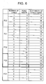
- Fig. 6 is a table showing a relationship between the number of lanes of a road and a shiftwidth for a display position of a street name for each road type.
- the table showing this relationship is stored in the storage unit 17.
- a road width corresponding to the number of lanes and a shiftwidth for a street name in accordance with the road width are defined for each road type. For example, in a case of a road with a function class FC3, if the number of lanes is five or more, it is defined that the road width is 11 dots and the shiftwidth for a street name in this case is 17 dots.
- Fig. 7 is a flowchart showing exemplary processing for displaying a map around a vehicle position.
- Fig. 8 is a flowchart showing exemplary processing for calculating a display position of road-related information.
- step S11 in Fig. 7 a vehicle position is detected by using a signal from the GPS receiver 3.
- step S12 map data around the vehicle position is acquired.
- the map data corresponding to a range to be displayed on a screen with a predetermined scale is extracted from map data stored in the DVD-ROM 1a.
- step S13 a display position of road-related information is calculated. Processing for calculating the display position will be described in more detail below.
- step S14 a map around the vehicle position including the road-related information at the optimal display position is displayed on the display screen.
- step S15 it is determined whether a stop instruction is given for the map display. If the stop instruction for the map display is given as a result of that, for example, an engine stops, or the user changes the display, the processing is ended. If no instruction is given, the processing returns to step S11, and continuously performs the processing for displaying the map around the vehicle position.
- Fig. 8 illustrates the exemplary processing for calculating the display position of the road-related information.
- step S21 in Fig. 8 data of a road to be displayed and data of road-related information related to the road are acquired.
- step S22 the number of lanes of the road is detected.
- the number of lanes is previously stored in part of the map database, as road information data of the map data.
- step S23 a shiftwidth for the display position of the road-related information corresponding to the number of lanes of the road detected in step S22 is detected.
- the shiftwidth is previously defined in accordance with the road type and the number of lanes of the road (width), and is stored in the storage unit 17.
- step S24 the display position of the road-related information is calculated on the basis of the shiftwidth acquired in step S23.
- the position data is stored in the storage unit 17.
- step S25 it is determined whether display positions of road-related information have been determined for all roads to be displayed. If the display positions of the road-related information have been determined not for all roads, the processing returns to step S24, and the display positions are continuously calculated. If the display positions for all roads to be displayed have been determined, the processing is ended, and the processing goes to step S14 in Fig. 7 .
- the display position of the road-related information is calculated by using adjustment data information (shiftwidth) indicative of a distance by which the road-related information stored in association with the road data is shifted from the road.
- the road-related information is displayed on the basis of the calculation result. Accordingly, even if the road width is changed to a road width defined in accordance with a road type and the number of lanes of the road, the display of the road-related information does not overlap the road. Thus, the map can be easily viewed.
- the position adjustment data for displaying the road-related information (street name etc.) defined such that the shiftwidth is associated with the road is stored separately from the map data. Hence, the display position of the road-related information is determined when the map is displayed, and the road-related information is displayed at the determined position.
- the map data does not have to be entirely updated.
- the road-related information can be displayed at the optimal position easily and quickly.
- the display position of the road-related information is calculated with reference to the position adjustment data and is displayed every time when the map around the vehicle position is displayed.
- the map may be displayed, and updated data for the display position of the road-related information may be reflected on the map data. Then, the updated data may be re-used when the map for the same region is displayed. In this case, the calculation for changing the position of the road-related information can be omitted.
- the road-related information may include an intersection name, a road sign (icon figure indicative of a road number), etc., as long as the information relates to a road.
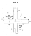
- Fig. 9 illustrates an exemplary display of an intersection name and a road sign.
- Fig. 9 provides an exemplary map display near an intersection 91 where a road 91a (with a road width of RW2) intersects with a road 91b (with a road width of RW3).
- a balloon-like intersection-name display icon 92 shows an intersection name "ABC intersection" along the road 91a.
- a reference line of the road 91a is a center line 93 of the road 91a
- a reference line of the display icon 92 is a side 94 of the display icon 92, the side 94 being parallel to the road 91a that corresponds to the display icon 92 and being near the road 91a.
- a distance (shiftwidth) SW2 between the center line 93 that is the reference line of the road 91a and the side 94 that is the reference line of the display icon 92 is previously determined.
- the display position of the display icon 92 is determined with reference to the shiftwidth SW2.
- a road sign icon 95 is displayed along the road 91b.
- a reference line of the road 91b is a center line 96 of the road 91b
- a reference line of the road sign icon 95 is a side 97a of the road sign icon 95, the side 97a being parallel to the road 91b and being near the road 91b, from among sides of a rectangular frame 97 that is a virtual outer frame of the road sign icon 95.
- a distance (shiftwidth) SW3 between the center line 96 that is the reference line of the road 91b and the side 97a that is the reference line of the road sign icon 95 are previously determined.
- the display position of the road sign icon 95 is determined with reference to the shiftwidth SW3.
Abstract
Description
- The present invention relates to a map display device and a map display method, and more particularly to a map display device and a map display method that have a function for displaying a street name at an optimal position in accordance with a road width.
- A typical on-vehicle navigation device of related art includes a control device, such as a CPU, that controls all processing related to navigation; a storage device, such as a digital versatile disk read only memory (DVD-ROM) or an integrated circuit (IC) memory card, that previously stores map data; a display device; a global positioning system (GPS) receiver; and detectors, such as a gyro and a vehicle speed sensor, that detect a current position and a current azimuth of a vehicle. The control device reads map data including the current position of the vehicle from the storage device. The control device causes the display device to display a map image around the vehicle position on a screen of the display device by using the map data. Also, the control device causes the display device to display a vehicle position mark indicative of the current position of the vehicle in a superposed manner on the map image, so that the map image is scrolled to follow travel of the vehicle, or the map image is fixed to the screen and the vehicle position mark is moved. Thus, a user can quickly recognize where the vehicle currently travels.
- In addition, the on-vehicle navigation device typically has a guide function (route guide function) for allowing the user to easily travel to a destination without traveling on a wrong road. With the route guide function, the CPU uses the map data and searches an optimal route from a departure place (normally, a current position of the vehicle) to a destination by simulation of, for example, breadth-first search or Dijkstra's algorithm. The searched route is stored as a guide route and the guide route is displayed on a map image during traveling such that the guide route can be distinguished from the other roads (for example, by changing the color or line width of the guide route). Also, when the vehicle approaches a position at a predetermined distance from an intersection in the guide route, at which the vehicle changes the course, a guide view of the intersection (for example, an enlarged view of the intersection, an arrow indicative of a travel direction of the vehicle at the intersection, a distance to the intersection, and an intersection name) is displayed on the map image. Thus, the user can recognize which road the user travels, and which direction the user travels ahead at the intersection.
- Roads and facilities are displayed on the map image of the on-vehicle navigation device in accordance with map data Also, names of the roads and facilities are displayed on the map image. Accordingly, the user can easily recognize the road and the position on the road where the vehicle currently travels, and facilities around the vehicle.
- When the names are displayed, if the density of the names to be displayed varies depending on the scale of the map, the names may overlap one another, or the name of a facility may overlap another facility. The user may have difficulty in viewing the map, or the user may not effectively use the map.
- As a technique that provides easy viewing of a map display, Japanese Unexamined Patent Application Publication No.
05-061405 - Japanese Unexamined Patent Application Publication No.
07-168524 - Japanese Unexamined Patent Application Publication No.
05-181414 - Japanese Unexamined Patent Application Publication No.
05-281903 - Japanese Unexamined Patent Application Publication No.
08-006496 - As described above, even when the map is enlarged and reduced, the characters and symbols are stored separately from the map data, and the characters and symbols are displayed with a uniform size, or the names of the facilities are displayed so as not to overlap one another. Thus, the techniques provide easy viewing of the map.
- Meanwhile, a road width of a road to be displayed is previously defined in map data. The road with the road width is displayed on the basis of the definition. A display of a character or a symbol is effective for the predefined road width.
- If the map data, for example, the road width is displayed recognizably, in particular, if the road width is changed in accordance with the actual number of lanes of the road, a display of a name related to the road may overlap the road depending on the width of a line of the road. The user may have difficulty in viewing the display.
- To address this, definition may be previously given such that a display of a related name is changed if a road display is changed. However, map data has to be entirely updated to reflect the changed display. The update may take time and be troublesome work.
- The present invention is made to address the disadvantages of the related art, and an object of the present invention is to provide a map display device and a map display method that can change a display position of road-related information easily and efficiently without entirely updating map data.
- To address the disadvantages of the related art, according to an aspect of the present invention, a map display device that displays a map image around a vehicle position is provided. The map display device includes a display unit; a first storage unit storing map data including road data of a road and road-related information related to the road; a second storage unit storing adjustment data indicative of a relationship between a display position of the road data and a display position of the road-related information; and a map display control unit for calculating the display position of the road-related information related to the road on the basis of the adjustment data for the individual road, and displaying the road-related information on a screen of the display unit.
- In the map display device according to the aspect, a road width when the road is displayed on the screen of the display unit may be determined in accordance with the number of lanes and a road type of the road. The adjustment data may be a distance between the display position of the road and the display position of the road-related information, and may be determined in accordance with the road type and the road width of the road.
- In the map display device according to the aspect, the map display control unit may extract a distance between a reference line for displaying the road-related information in accordance with the road type and the road width of the road and a reference line of the road from the adjustment data stored in the second storage unit, and may calculate the display position of the road-related information in accordance with the distance. The reference line for displaying the road-related information may be a center line of a display frame for a region in which the road-related information is displayed, the center line being parallel to the road that corresponds to the display frame. Alternatively, the reference line for displaying the road-related information may be a side of a display frame for a region in which the road-related information is displayed, the side being parallel to the road that corresponds to the display frame and being near the road. The reference line of the road may be a center line of the road. Alternatively, the reference line of the road may be a side of the road, the side being parallel to the display frame and being near the display frame.
- According to another aspect of the present invention, a map display method performed in the map display device according to the above aspect is provided. The map display method according to this aspect generates a map image by using map data including map character data having a street name, and adjustment data indicative of a relationship between a display position of a street name and a display position of a road. The method includes the steps of detecting a current vehicle position; extracting the map data around the vehicle position; acquiring the adjustment data indicative of the relationship between the display position of the road data and the display position of the road-related information included in the map data; calculating the display position of the road-related information related to the road on the basis of the adjustment data in accordance with the road width; and generating the map image including the road-related information on the basis of the calculated position, and displaying the map image on a screen of a display unit.
- In the map display method according to the aspect, the calculation for the display position of the road-related information related to the road on the basis of the adjustment data in accordance with the road width may include the steps of extracting a distance between a reference line for displaying the road-related information in accordance with a road type and a road width of the road and a reference line of the road from the adjustment data stored in a storage unit, and calculating the display position of the road-related information in accordance with the distance. The reference line for displaying the road-related information may be a center line of a display frame for a region in which the road-related information is displayed, the center line being parallel to the road that corresponds to the display frame. Alternatively, the reference line for displaying the road-related information may be a side of a display frame for a region in which the road-related information is displayed, the side being parallel to the road that corresponds to the display frame and being near the road. The reference line of the road may be a center line of the road. Alternatively, the reference line of the road may be a side of the road, the side being parallel to the display frame and being near the display frame.
- With the map display device and the map display method according to the aspects of the present invention, the display position of the road-related information is calculated on the basis of the adjustment data information (shiftwidth) indicative of a distance by which the road-related information stored in associated with the road data is shifted from the road when the map is displayed. The road-related information is displayed on the basis of the calculation result. Accordingly, even if the road width is changed to the road width defined on the basis of the road type and the number of lanes of the road, the display of the road-related information does not overlap the road. The map display can be easily viewed.
- In addition, since the shiftwidth is defined in association with the road, the display position of the road-related information is determined and the road-related information is displayed at the determined position when the map is displayed. The map data does not have to be entirely updated. The road-related information can be easily and quickly displayed at the optimal position.
-
-
Fig. 1 is a block diagram showing a configuration of an on-vehicle navigation device having a function of a map display device according to an embodiment of the present invention; -
Figs. 2A and 2B illustrate an exemplary map display when road widths are not changed in accordance with road types, and an exemplary map display when the road widths are changed in accordance with the road types as compared with the map display inFig. 2A ; -
Figs. 3A and 3B illustrate an exemplary map display when the road widths are not changed in accordance with road types, and an exemplary map display when the road widths are changed in accordance with the road types and when street names are displayed at optimal positions; -
Figs. 4A and 4B each illustrate a configuration of a road database; -
Figs. 5A to 5C each illustrate a relationship between a display position of a road and a display position of a street name; -
Fig. 6 is a table showing a relationship between the number of lanes of a road and a shiftwidth for a display position of the street name for each road type; -
Fig. 7 is a flowchart showing exemplary processing for displaying a map in the map display device inFig. 1 ; -
Fig. 8 is a flowchart showing exemplary processing for calculating a display position of road-related information in the flowchart inFig. 7 ; and -
Fig. 9 illustrates a relationship between display positions of roads and display positions of an intersection name and a road sign. - An embodiment of the present invention will be described below with reference to the attached drawings. Configuration of On-vehicle Navigation Device
-
Fig. 1 is a block diagram showing a configuration of an on-vehicle navigation device 100 having a function of a map display device, as an embodiment for a map display device of the present invention. - Referring to
Fig. 1 , a DVD-ROM drive 1 is illustrated. A storage medium stores map data and guide data. In this embodiment, the storage medium that stores such data is a DVD-ROM 1a. However, hard disk or another storage medium may be used. The map stored in the DVD-ROM 1a is divided into longitude widths and latitude widths with proper sizes depending on scales, for example, 1/12500, 1/25000, 1/50000, and 1/100000. Various objects including roads, buildings, and facilities in the map are stored as sets of coordinates of nodes expressed with the longitude and latitude. The map data includes (1) a road layer having a road list, a node table, an intersection-nodes list, etc., (2) a background layer for displaying roads, buildings, parks, rivers, etc., on a map image, and (3) a characters-and-symbols layer for displaying characters and map symbols to identify names of administrative districts like municipal districts, street names, intersection names, etc. - The DVD-
ROM 1a also stores road data that expresses shapes of roads that are used for map matching. The road data includes links between shape nodes. Distances between the nodes differ from one another in accordance with the shapes of the roads. - An
operation unit 2 includes operation buttons and the like for operating anavigation device body 10. In this embodiment, theoperation unit 2 includes a remote-controller transmitter. A user may operate thenavigation device body 10 by using the remote-controller transmitter. - A
GPS receiver 3 receives GPS signals transmitted from a plurality of GPS satellites; generates GPS data including a longitude and a latitude of a current position of a vehicle, and GPS data including position dilution of precision (position DOP, PDOP) and a horizontal position dilution of precision (HDOP); and outputs the GPS data. -
Various sensors 4 include a self-contained navigation sensor, an acceleration sensor, and a steering-angle sensor. The self-contained navigation sensor includes an angle sensor such as a gyro that detects a rotation angle of a vehicle, and a travel distance sensor that generates a pulse every predetermined travel distance. The acceleration sensor detects an operated state of a brake. The steering-angle sensor detects an operated state of a steering wheel. - A
communication device 5 is, for example, a mobile phone for communication between the user and various service centers. A vehicle information and communication system (VICS)receiver 6 receives information from radio beacons or optical beacons. These beacons are provided at roadsides. The beacons are connected with police offices, road administrators, and an integrated center. - A
display unit 7 is, for example, a liquid crystal panel. Thenavigation device body 10 causes thedisplay unit 7 to display a map around a current position of the vehicle, a guide route from a departure place to a destination, a vehicle mark, and other guide information. Thedisplay unit 7 includes a touch panel on a screen thereof. The touch panel includes various buttons corresponding to display contents of a displayed screen.
The touch panel also serves as an input device to select menus in the form of various buttons. Aspeaker 8 provides guide information to the user with voice. - The
navigation device body 10 includes following components. Abuffer memory 11 temporarily stores the map data read from the DVD-ROM 1a through the DVD-ROM drive 1. - A
control unit 12 is a microcomputer including a navigation program. Under the program, thecontrol unit 12 executes various processing including calculating a current position of the vehicle by using a signal output from theGPS receiver 3 and a signal output from the self-contained navigation sensor included in thevarious sensors 4; reading map data to be displayed from the DVD-ROM 1a through the DVD-ROM drive 1 and providing the read map data to thebuffer memory 11; and searching a guide route from a departure place to a destination to meet a search condition determined with the map data in thebuffer memory 11. In this embodiment, thecontrol unit 12 has a function of a map display control unit. When thecontrol unit 12 causes a screen of thedisplay unit 7 to display a road and a street name related to the road, thecontrol unit 12 adjusts a distance between a display position of the road and a display position of the street name etc., and determines the display positions. Thus, thecontrol unit 12 performs processing for displaying a map that can be easily viewed. - A
map drawing unit 13 generates a map image by using the map data in thebuffer memory 11. An operation screen and mark generatingunit 14 generates various menu screens (operation screens) in accordance with operated states, a vehicle position mark, and various marks such as cursors. - A guide
route storage unit 15 stores the guide route searched by thecontrol unit 12. A guideroute drawing unit 16 draws a guide route. The guideroute storage unit 15 stores all nodes in the guide route searched by thecontrol unit 12, from the departure place to the destination. The guideroute drawing unit 16 reads guide route information from the guideroute storage unit 15 when the map is displayed, and draws the guide route with a color and a line width different from those of the other roads. - A
storage unit 17 is, for example, hard disk. Thestorage unit 17 stores data for adjusting, for example, a position of a street name with respect to a position of a road displayed on a screen of thedisplay unit 7. - A
voice output unit 18 supplies thespeaker 8 with a voice signal on the basis of a signal from thecontrol unit 12. Animage combining unit 19 superposes the various marks and the operation screen generated by the operation screen and mark generatingunit 14, and the guide route drawn by the guideroute drawing unit 16, on the map image drawn by themap drawing unit 13. The resultant map image is displayed on thedisplay unit 7. - Described next is a display of a map image when the widths of roads are changed in accordance with road types by the on-
vehicle navigation device 100 with the above configuration. -
Fig. 2A illustrates an example of amap image 21 that is displayed on the screen of thedisplay unit 7 when the widths of roads are not changed in accordance with the numbers of lanes of the roads. Roads (25, 26, 27, 28, and 29) with different widths in accordance with road types, avehicle position mark 24 indicative of a current position of the vehicle, anazimuth mark 22, and astate display section 23 are displayed on themap image 21 inFig. 2A . Thestate display section 23 indicates that the vehicle currently travels to the west along the 55th street (W 55TH ST). Referring toFig. 2A , theroads road 26. Hence, theroads road 26. If the widths of the roads are not changed in accordance with the numbers of lanes of the roads, the street names (54TH, etc.) are displayed generally at distances from the roads to prevent the street names from overlapping the display of the roads. -
Fig. 2B illustrates an example of a map image when the widths of roads are changed in accordance with the road types (thus, theroads roads Fig. 2A . The street names are data independent from data of the roads. Even if the widths of the roads are changed, the display positions of the street names are not changed. Thus, a road may overlap a street name depending on the width of the road, or a street name may be too far from a road. - In
Fig. 2B , the positional relationship between theroad 28a and its street name "FLOWER" is proper. However, theroad 25a overlaps its street name "FIGUEROA," and theroad 29a is too far from its street name "HOOVER." -
Figs. 3A and 3B illustrate an example in which a street name is displayed at a proper position such that a street name does not overlap a road or is not too far from the road when the widths of the roads are changed in accordance with the road types.Fig. 3A is the same figure asFig. 2A , and illustrates a map image when the widths of roads are not changed in accordance with the numbers of lanes of the roads -
Fig. 3B illustrates a map image when the widths of the roads are changed in accordance with the numbers of lanes of the roads, as compared with the map image inFig. 3A . Referring toFig. 3B , the street name "FIGUEROA," which overlaps the road inFig. 2B , is separated from the road, and the street name "HOOVER," which is too far from the road inFig. 2B , is displayed at a proper distance from the road. - Optimization processing for the display position of the street name will be described below with reference to the drawings.
Figs. 4A and 4B each illustrate a primary configuration of a road database.Fig. 4A illustrates part of the content of the map database. The map database includes roads and street name information.Fig. 4B illustrates part of a directory structure of information data related to a street name. - The road layer in the map data includes road link data, node data, and intersection data. The road link data is data related to roads that connect intersections with one another. The road link data includes node data indicative of longitudes and latitudes of a start point and an end point of a road, a road type (national road, highway, prefectural road, other local road and street), the number of nodes that form a link, a street name, a road width, and the number of lanes of a road, for each link that forms a road.
- In the United States, the road types are classified into five function classes (FCO to FC4) based on the road network by Navigation Technologies. FC0 corresponds to Super Highways, FC1 corresponds to Highways, FC2 corresponds to Collector Roads, FC3 corresponds to Feeder Roads, and FC4 corresponds to Local Streets.
- Referring to
Fig. 4B , the information related to the display of the street is written in a Road Text Data Type directory, as data, for example, in the form of files. The Road Text Data Type directory includes a Road Information directory and a TEXT directory, and has a Text Center X file and a Text center Y file. The Text Center X file and the Text center Y file respectively indicate an X coordinate and a Y coordinate of the center of a text (street name). - The Road Information directory saves data of road information, and has a Function Road Class file and a Number of Lanes file. The Function Road Class file saves a road type, and the Number of Lanes file saves the number of lanes of a road.
- The TEXT directory further includes a Text Record directory. The Text Record directory has a String Angle file, a Char Angle file, and a String file. The String Angle file saves an angle of a street name string to be displayed, the Char Angle file saves an angle of characters of the street name to be displayed, and the String file saves a string of the street name to be displayed. In
Fig. 4B , FIGUEROA is saved as the string of the street name. -
Figs. 5A to 5C each illustrate calculation of a display position of a street name. InFig. 5A , acenter line 53 of a road 51 (with a road width of RW1) serves as a reference line of theroad 51, and acenter line 54 of adisplay frame 52 for a street name serves as a reference line for displaying the street name, thecenter line 54 being parallel to theroad 51. - The street name is displayed within the
display frame 52 for the street name. The XY coordinates of the center of the display is previously defined as shown inFig. 4B . For example, if a road is parallel to the X direction, the X coordinate of the center of the display position of the street name is the same as the defined X coordinate, and the Y coordinate thereof is obtained by adding a shiftwidth SW1 to the Y coordinate of thecenter line 53 of theroad 51. Thus, by calculating the display position of the street name, the street name is displayed at a proper position without overlapping the display of the road. - The
display frame 52 for the street name is a region in which the string of the street name is displayed. Thedisplay frame 52 may be displayed or may not be displayed when the map is displayed. - In
Fig. 5B , thecenter line 53 of theroad 51 serves as the reference line of theroad 51, and aside 55 of thedisplay frame 52 for the street name serves as a reference line for displaying the street name, theside 55 being parallel to theroad 51 and being near theroad 51. Calculation for the display position of the street name is similar to that inFig. 5A . - The shiftwidth for the street name from the road is the shiftwidth SW1 from the
center line 53 of theroad 51 to the lower end of thedisplay frame 52 for the street name. Thus, even if the font size of the string displayed within thedisplay frame 52 for the street name is changed, the shiftwidth SW1 of the street name does not have to be corrected. - In
Fig. 5C , aside 56 of theroad 51 serves as a reference line of theroad 51, theside 56 being parallel to thedisplay frame 52 and being near thedisplay frame 52 for the street name, and theside 55 of thedisplay frame 52 for the street name serves as the reference line of the street name, theside 55 being parallel to theroad 51 and being near theroad 51. Calculation for the display position of the street name is similar to that inFig. 5A . - The shiftwidth for the street name from the road is the shiftwidth SW1 from the
side 56 of theroad 51 to the lower end of thedisplay frame 52 for the street name. Thus, even if the drawn width of theroad 51 is changed, the shiftwidth SW1 of the street name does not have to be corrected. Also, even if the font size of the string to be displayed within thedisplay frame 52 for the street name is changed, the shiftwidth SW1 of the street name does not have to be corrected. -
Fig. 6 is a table showing a relationship between the number of lanes of a road and a shiftwidth for a display position of a street name for each road type. The table showing this relationship is stored in thestorage unit 17. Referring toFig. 6 , a road width corresponding to the number of lanes and a shiftwidth for a street name in accordance with the road width are defined for each road type. For example, in a case of a road with a function class FC3, if the number of lanes is five or more, it is defined that the road width is 11 dots and the shiftwidth for a street name in this case is 17 dots. - Next, a map display method performed in the map display device according to this embodiment will be described. Processing for calculating a display position of road-related information in the map display method will be described in detail below with reference to flowcharts shown in
Figs. 7 and8 . -
Fig. 7 is a flowchart showing exemplary processing for displaying a map around a vehicle position.Fig. 8 is a flowchart showing exemplary processing for calculating a display position of road-related information. - In step S11 in
Fig. 7 , a vehicle position is detected by using a signal from theGPS receiver 3. - In step S12, map data around the vehicle position is acquired. The map data corresponding to a range to be displayed on a screen with a predetermined scale is extracted from map data stored in the DVD-
ROM 1a. - In step S13, a display position of road-related information is calculated. Processing for calculating the display position will be described in more detail below.
- In step S14, a map around the vehicle position including the road-related information at the optimal display position is displayed on the display screen.
- In step S15, it is determined whether a stop instruction is given for the map display. If the stop instruction for the map display is given as a result of that, for example, an engine stops, or the user changes the display, the processing is ended. If no instruction is given, the processing returns to step S11, and continuously performs the processing for displaying the map around the vehicle position.
-
Fig. 8 illustrates the exemplary processing for calculating the display position of the road-related information. In step S21 inFig. 8 , data of a road to be displayed and data of road-related information related to the road are acquired. - In step S22, the number of lanes of the road is detected. The number of lanes is previously stored in part of the map database, as road information data of the map data.
- In step S23, a shiftwidth for the display position of the road-related information corresponding to the number of lanes of the road detected in step S22 is detected. The shiftwidth is previously defined in accordance with the road type and the number of lanes of the road (width), and is stored in the
storage unit 17. - In step S24, the display position of the road-related information is calculated on the basis of the shiftwidth acquired in step S23. The position data is stored in the
storage unit 17. - In step S25, it is determined whether display positions of road-related information have been determined for all roads to be displayed. If the display positions of the road-related information have been determined not for all roads, the processing returns to step S24, and the display positions are continuously calculated. If the display positions for all roads to be displayed have been determined, the processing is ended, and the processing goes to step S14 in
Fig. 7 . - As described above, with the map display device and the map display method according to this embodiment, when the map is displayed, the display position of the road-related information is calculated by using adjustment data information (shiftwidth) indicative of a distance by which the road-related information stored in association with the road data is shifted from the road. The road-related information is displayed on the basis of the calculation result. Accordingly, even if the road width is changed to a road width defined in accordance with a road type and the number of lanes of the road, the display of the road-related information does not overlap the road. Thus, the map can be easily viewed.
- The position adjustment data for displaying the road-related information (street name etc.) defined such that the shiftwidth is associated with the road is stored separately from the map data. Hence, the display position of the road-related information is determined when the map is displayed, and the road-related information is displayed at the determined position. The map data does not have to be entirely updated. The road-related information can be displayed at the optimal position easily and quickly.
- In the above embodiment, the display position of the road-related information is calculated with reference to the position adjustment data and is displayed every time when the map around the vehicle position is displayed. Also, the map may be displayed, and updated data for the display position of the road-related information may be reflected on the map data. Then, the updated data may be re-used when the map for the same region is displayed. In this case, the calculation for changing the position of the road-related information can be omitted.
- In the above embodiment, the adjustment for the display position of the street name as the road-related information has been described. However, it is not limited thereto.
The road-related information may include an intersection name, a road sign (icon figure indicative of a road number), etc., as long as the information relates to a road. - For example,
Fig. 9 illustrates an exemplary display of an intersection name and a road sign.Fig. 9 provides an exemplary map display near anintersection 91 where aroad 91a (with a road width of RW2) intersects with aroad 91b (with a road width of RW3). A balloon-like intersection-name display icon 92 shows an intersection name "ABC intersection" along theroad 91a. In this case, a reference line of theroad 91a is acenter line 93 of theroad 91a, and a reference line of thedisplay icon 92 is aside 94 of thedisplay icon 92, theside 94 being parallel to theroad 91a that corresponds to thedisplay icon 92 and being near theroad 91a. A distance (shiftwidth) SW2 between thecenter line 93 that is the reference line of theroad 91a and theside 94 that is the reference line of thedisplay icon 92 is previously determined. When thedisplay icon 92 is displayed, the display position of thedisplay icon 92 is determined with reference to the shiftwidth SW2. - A
road sign icon 95 is displayed along theroad 91b.
In this case, a reference line of theroad 91b is acenter line 96 of theroad 91b, and a reference line of theroad sign icon 95 is a side 97a of theroad sign icon 95, the side 97a being parallel to theroad 91b and being near theroad 91b, from among sides of a rectangular frame 97 that is a virtual outer frame of theroad sign icon 95. - A distance (shiftwidth) SW3 between the
center line 96 that is the reference line of theroad 91b and the side 97a that is the reference line of theroad sign icon 95 are previously determined. When theroad sign icon 95 is displayed, the display position of theroad sign icon 95 is determined with reference to the shiftwidth SW3.
Claims (9)
- A map display device that displays a map image around a vehicle position, comprising:display means (7);first storage means (1a) storing map data including road data of a road and road-related information related to the road;second storage means (17) storing adjustment data indicative of a relationship between a display position of the road data and a display position of the road-related information; andmap display control means (12) for calculating the display position of the road-related information related to the road on the basis of the adjustment data for the individual road, and displaying the road-related information on a screen of the display means (7).
- The map display device according to claim 1,
wherein a road width when the road is displayed on the screen of the display means (7) is determined in accordance with the number of lanes and a road type of the road. - The map display device according to claim 2,
wherein the adjustment data is a distance between the display position of the road and the display position of the road-related information, and is determined in accordance with the road type and the road width of the road. - The map display device according to claim 3,
wherein the map display control means (12) extracts a distance between a reference line for displaying the road-related information, in accordance with the road type and the road width of the road, and a reference line of the road from the adjustment data stored in the second storage means (17), and calculates the display position of the road-related information in accordance with the distance. - The map display device according to claim 4,
wherein the reference line for displaying the road-related information is a center line of a display frame for a region in which the road-related information is displayed, the center line being parallel to the road that corresponds to the display frame. - The map display device according to claim 4,
wherein the reference line for displaying the road-related information is a side of a display frame for a region in which the road-related information is displayed, the side being parallel to the road that corresponds to the display frame and being nearest the road. - The map display device according to claim 5 or 6,
wherein the reference line of the road is a center line of the road. - The map display device according to claim 5 or 6,
wherein the reference line of the road is a side of the road, the side being parallel to the display frame and being nearest the display frame. - The map display device according to any preceding claim, wherein the road-related information is one of a street name, an intersection name, and a road sign.
Applications Claiming Priority (1)
| Application Number | Priority Date | Filing Date | Title |
|---|---|---|---|
| JP2009242055A JP5554045B2 (en) | 2009-10-21 | 2009-10-21 | Map display device and map display method |
Publications (3)
| Publication Number | Publication Date |
|---|---|
| EP2317282A2 true EP2317282A2 (en) | 2011-05-04 |
| EP2317282A3 EP2317282A3 (en) | 2014-02-26 |
| EP2317282B1 EP2317282B1 (en) | 2019-09-04 |
Family
ID=43733980
Family Applications (1)
| Application Number | Title | Priority Date | Filing Date |
|---|---|---|---|
| EP10169810.8A Active EP2317282B1 (en) | 2009-10-21 | 2010-07-16 | Map display device and map display method |
Country Status (3)
| Country | Link |
|---|---|
| US (1) | US8504297B2 (en) |
| EP (1) | EP2317282B1 (en) |
| JP (1) | JP5554045B2 (en) |
Families Citing this family (6)
| Publication number | Priority date | Publication date | Assignee | Title |
|---|---|---|---|---|
| JP4553033B2 (en) * | 2008-05-15 | 2010-09-29 | 株式会社デンソー | Current position calculation device and program |
| DE102012222931A1 (en) * | 2012-12-12 | 2014-06-12 | Robert Bosch Gmbh | Method for determining e.g. position and/or type of road sign, involves reading set of records, where each record comprises positional data representing different geographical positions, transaction data and vehicle specifications |
| WO2017044804A1 (en) * | 2015-09-10 | 2017-03-16 | Benavides Miguel | Method and system for visualization of position data |
| JP6607139B2 (en) * | 2016-04-26 | 2019-11-20 | トヨタ自動車株式会社 | Information collection system |
| CN107687863B (en) * | 2017-08-31 | 2019-12-06 | 城市生活(北京)资讯有限公司 | road name display method and system |
| CN111238503B (en) * | 2018-11-29 | 2022-12-02 | 沈阳美行科技股份有限公司 | Map generation method, device and related system for road segments |
Citations (5)
| Publication number | Priority date | Publication date | Assignee | Title |
|---|---|---|---|---|
| JPH0561405A (en) | 1991-09-02 | 1993-03-12 | Nissin Electric Co Ltd | In-figure name display device |
| JPH05181414A (en) | 1991-12-27 | 1993-07-23 | Fujitsu Ten Ltd | Map display device |
| JPH05281903A (en) | 1992-04-02 | 1993-10-29 | Nissan Motor Co Ltd | Navigation device for vehicle |
| JPH07168524A (en) | 1994-08-23 | 1995-07-04 | Zanabui Informatics:Kk | Navigation device |
| JPH086496A (en) | 1994-06-15 | 1996-01-12 | Nec Home Electron Ltd | Map display device |
Family Cites Families (24)
| Publication number | Priority date | Publication date | Assignee | Title |
|---|---|---|---|---|
| JPS57144589A (en) | 1981-03-04 | 1982-09-07 | Nissan Motor | Picture display unit |
| JP3568621B2 (en) * | 1995-04-20 | 2004-09-22 | 株式会社日立製作所 | Map display device |
| US7418346B2 (en) * | 1997-10-22 | 2008-08-26 | Intelligent Technologies International, Inc. | Collision avoidance methods and systems |
| JPH09210714A (en) * | 1996-01-31 | 1997-08-15 | Aisin Aw Co Ltd | Navigation device |
| KR100245267B1 (en) * | 1996-06-03 | 2000-02-15 | 모리 하루오 | Car navigation system |
| US6266442B1 (en) * | 1998-10-23 | 2001-07-24 | Facet Technology Corp. | Method and apparatus for identifying objects depicted in a videostream |
| US6565610B1 (en) * | 1999-02-11 | 2003-05-20 | Navigation Technologies Corporation | Method and system for text placement when forming maps |
| US6710774B1 (en) * | 1999-05-12 | 2004-03-23 | Denso Corporation | Map display device |
| JP3794875B2 (en) * | 1999-08-30 | 2006-07-12 | アイシン・エィ・ダブリュ株式会社 | Navigation device |
| JP3908419B2 (en) * | 1999-09-14 | 2007-04-25 | アルパイン株式会社 | Navigation device |
| JP3707770B2 (en) * | 2000-02-14 | 2005-10-19 | 松下電器産業株式会社 | Map information correction apparatus and map information correction method |
| JP3908437B2 (en) * | 2000-04-14 | 2007-04-25 | アルパイン株式会社 | Navigation system |
| US7075512B1 (en) * | 2002-02-07 | 2006-07-11 | Palmsource, Inc. | Method and system for navigating a display screen for locating a desired item of information |
| US7221287B2 (en) * | 2002-03-05 | 2007-05-22 | Triangle Software Llc | Three-dimensional traffic report |
| JP2004126036A (en) * | 2002-09-30 | 2004-04-22 | Xanavi Informatics Corp | Distribution map data structure, distribution map data preparation method, distribution map data preparation device, and terminal equipment |
| US7076363B1 (en) * | 2003-07-17 | 2006-07-11 | America Online, Inc. | Using route narrative symbols |
| JP4597496B2 (en) * | 2003-09-04 | 2010-12-15 | 三菱電機株式会社 | Display device |
| JP2006330112A (en) * | 2005-05-23 | 2006-12-07 | Pioneer Electronic Corp | Information generating device, its method, its program, and recording medium with program recorded thereon |
| WO2008099483A1 (en) * | 2007-02-15 | 2008-08-21 | Pioneer Corporation | Display controller, display control method, display control program, and recording medium |
| US20080243378A1 (en) * | 2007-02-21 | 2008-10-02 | Tele Atlas North America, Inc. | System and method for vehicle navigation and piloting including absolute and relative coordinates |
| JP4789827B2 (en) * | 2007-03-05 | 2011-10-12 | アルパイン株式会社 | Navigation device and freeway search method |
| JP4850133B2 (en) * | 2007-06-06 | 2012-01-11 | アルパイン株式会社 | Map display device and map display method |
| CN101815928A (en) * | 2007-10-02 | 2010-08-25 | 电子地图有限公司 | Method of capturing linear features along a reference-line across a surface for use in a map database |
| CA2712673A1 (en) * | 2008-02-04 | 2009-08-13 | Tele Atlas North America Inc. | Method for map matching with sensor detected objects |
-
2009
- 2009-10-21 JP JP2009242055A patent/JP5554045B2/en active Active
-
2010
- 2010-07-16 EP EP10169810.8A patent/EP2317282B1/en active Active
- 2010-09-30 US US12/895,172 patent/US8504297B2/en active Active
Patent Citations (5)
| Publication number | Priority date | Publication date | Assignee | Title |
|---|---|---|---|---|
| JPH0561405A (en) | 1991-09-02 | 1993-03-12 | Nissin Electric Co Ltd | In-figure name display device |
| JPH05181414A (en) | 1991-12-27 | 1993-07-23 | Fujitsu Ten Ltd | Map display device |
| JPH05281903A (en) | 1992-04-02 | 1993-10-29 | Nissan Motor Co Ltd | Navigation device for vehicle |
| JPH086496A (en) | 1994-06-15 | 1996-01-12 | Nec Home Electron Ltd | Map display device |
| JPH07168524A (en) | 1994-08-23 | 1995-07-04 | Zanabui Informatics:Kk | Navigation device |
Also Published As
| Publication number | Publication date |
|---|---|
| JP2011089819A (en) | 2011-05-06 |
| US8504297B2 (en) | 2013-08-06 |
| US20110093195A1 (en) | 2011-04-21 |
| EP2317282A3 (en) | 2014-02-26 |
| EP2317282B1 (en) | 2019-09-04 |
| JP5554045B2 (en) | 2014-07-23 |
Similar Documents
| Publication | Publication Date | Title |
|---|---|---|
| EP0827125B1 (en) | Land vehicle navigation apparatus with guidance display image limiter for recognizability enhancement | |
| EP0773525B1 (en) | Navigation apparatus for a vehicle taking into account the road width | |
| JP4435846B2 (en) | Location registration apparatus, location registration method, location registration program, and recording medium | |
| EP1852680A1 (en) | Guiding route generation device and guiding route generation method | |
| JP4096180B2 (en) | NAVIGATION DEVICE, PROGRAM FOR THE DEVICE, AND RECORDING MEDIUM | |
| JP4809900B2 (en) | Navigation device, map display method, and map display program | |
| US20040111215A1 (en) | Navigation system | |
| EP2317282B1 (en) | Map display device and map display method | |
| US8494769B2 (en) | Information system, terminal device, and information center device | |
| US8428865B2 (en) | Navigation system and roadway search method | |
| JP4936070B2 (en) | Navigation device and navigation program | |
| US7657369B2 (en) | Navigation device for a vehicle, method for producing data for a search, and method for searching for a guided route | |
| EP1406065A2 (en) | Recording medium storage hierarchical information, device, system, method, and computer program, and recording medium storing such computer program | |
| JP3561603B2 (en) | Car navigation system | |
| JP2002071369A (en) | On-vehicle navigation device | |
| JP4210869B2 (en) | NAVIGATION DEVICE, PROGRAM FOR THE DEVICE, AND RECORDING MEDIUM | |
| JP2001201353A (en) | Navigation device | |
| JPH08304101A (en) | Navigation device | |
| JPWO2008041338A1 (en) | Map display device, map display method, map display program, and recording medium | |
| JP5615607B2 (en) | Map display device and map display method | |
| JP5005454B2 (en) | On-vehicle navigation device and minute angle branch determination method | |
| JP4915298B2 (en) | Navigation device and program | |
| JP2008064468A (en) | Navigation device and information displaying method | |
| JP4413044B2 (en) | Navigation device | |
| JP5319330B2 (en) | Car navigation system |
Legal Events
| Date | Code | Title | Description |
|---|---|---|---|
| PUAI | Public reference made under article 153(3) epc to a published international application that has entered the european phase |
Free format text: ORIGINAL CODE: 0009012 |
|
| AK | Designated contracting states |
Kind code of ref document: A2 Designated state(s): AL AT BE BG CH CY CZ DE DK EE ES FI FR GB GR HR HU IE IS IT LI LT LU LV MC MK MT NL NO PL PT RO SE SI SK SM TR |
|
| AX | Request for extension of the european patent |
Extension state: BA ME RS |
|
| PUAL | Search report despatched |
Free format text: ORIGINAL CODE: 0009013 |
|
| AK | Designated contracting states |
Kind code of ref document: A3 Designated state(s): AL AT BE BG CH CY CZ DE DK EE ES FI FR GB GR HR HU IE IS IT LI LT LU LV MC MK MT NL NO PL PT RO SE SI SK SM TR |
|
| AX | Request for extension of the european patent |
Extension state: BA ME RS |
|
| RIC1 | Information provided on ipc code assigned before grant |
Ipc: G01C 21/36 20060101AFI20140121BHEP |
|
| 17P | Request for examination filed |
Effective date: 20140306 |
|
| RBV | Designated contracting states (corrected) |
Designated state(s): AL AT BE BG CH CY CZ DE DK EE ES FI FR GB GR HR HU IE IS IT LI LT LU LV MC MK MT NL NO PL PT RO SE SI SK SM TR |
|
| 17Q | First examination report despatched |
Effective date: 20160708 |
|
| STAA | Information on the status of an ep patent application or granted ep patent |
Free format text: STATUS: EXAMINATION IS IN PROGRESS |
|
| GRAP | Despatch of communication of intention to grant a patent |
Free format text: ORIGINAL CODE: EPIDOSNIGR1 |
|
| STAA | Information on the status of an ep patent application or granted ep patent |
Free format text: STATUS: GRANT OF PATENT IS INTENDED |
|
| INTG | Intention to grant announced |
Effective date: 20190318 |
|
| GRAS | Grant fee paid |
Free format text: ORIGINAL CODE: EPIDOSNIGR3 |
|
| GRAA | (expected) grant |
Free format text: ORIGINAL CODE: 0009210 |
|
| STAA | Information on the status of an ep patent application or granted ep patent |
Free format text: STATUS: THE PATENT HAS BEEN GRANTED |
|
| AK | Designated contracting states |
Kind code of ref document: B1 Designated state(s): AL AT BE BG CH CY CZ DE DK EE ES FI FR GB GR HR HU IE IS IT LI LT LU LV MC MK MT NL NO PL PT RO SE SI SK SM TR |
|
| REG | Reference to a national code |
Ref country code: GB Ref legal event code: FG4D |
|
| REG | Reference to a national code |
Ref country code: CH Ref legal event code: EP |
|
| REG | Reference to a national code |
Ref country code: AT Ref legal event code: REF Ref document number: 1176001 Country of ref document: AT Kind code of ref document: T Effective date: 20190915 |
|
| REG | Reference to a national code |
Ref country code: DE Ref legal event code: R096 Ref document number: 602010060856 Country of ref document: DE |
|
| REG | Reference to a national code |
Ref country code: IE Ref legal event code: FG4D |
|
| REG | Reference to a national code |
Ref country code: NL Ref legal event code: MP Effective date: 20190904 |
|
| REG | Reference to a national code |
Ref country code: LT Ref legal event code: MG4D |
|
| PG25 | Lapsed in a contracting state [announced via postgrant information from national office to epo] |
Ref country code: BG Free format text: LAPSE BECAUSE OF FAILURE TO SUBMIT A TRANSLATION OF THE DESCRIPTION OR TO PAY THE FEE WITHIN THE PRESCRIBED TIME-LIMIT Effective date: 20191204 Ref country code: SE Free format text: LAPSE BECAUSE OF FAILURE TO SUBMIT A TRANSLATION OF THE DESCRIPTION OR TO PAY THE FEE WITHIN THE PRESCRIBED TIME-LIMIT Effective date: 20190904 Ref country code: NO Free format text: LAPSE BECAUSE OF FAILURE TO SUBMIT A TRANSLATION OF THE DESCRIPTION OR TO PAY THE FEE WITHIN THE PRESCRIBED TIME-LIMIT Effective date: 20191204 Ref country code: FI Free format text: LAPSE BECAUSE OF FAILURE TO SUBMIT A TRANSLATION OF THE DESCRIPTION OR TO PAY THE FEE WITHIN THE PRESCRIBED TIME-LIMIT Effective date: 20190904 Ref country code: LT Free format text: LAPSE BECAUSE OF FAILURE TO SUBMIT A TRANSLATION OF THE DESCRIPTION OR TO PAY THE FEE WITHIN THE PRESCRIBED TIME-LIMIT Effective date: 20190904 Ref country code: HR Free format text: LAPSE BECAUSE OF FAILURE TO SUBMIT A TRANSLATION OF THE DESCRIPTION OR TO PAY THE FEE WITHIN THE PRESCRIBED TIME-LIMIT Effective date: 20190904 |
|
| PG25 | Lapsed in a contracting state [announced via postgrant information from national office to epo] |
Ref country code: GR Free format text: LAPSE BECAUSE OF FAILURE TO SUBMIT A TRANSLATION OF THE DESCRIPTION OR TO PAY THE FEE WITHIN THE PRESCRIBED TIME-LIMIT Effective date: 20191205 Ref country code: ES Free format text: LAPSE BECAUSE OF FAILURE TO SUBMIT A TRANSLATION OF THE DESCRIPTION OR TO PAY THE FEE WITHIN THE PRESCRIBED TIME-LIMIT Effective date: 20190904 Ref country code: LV Free format text: LAPSE BECAUSE OF FAILURE TO SUBMIT A TRANSLATION OF THE DESCRIPTION OR TO PAY THE FEE WITHIN THE PRESCRIBED TIME-LIMIT Effective date: 20190904 Ref country code: AL Free format text: LAPSE BECAUSE OF FAILURE TO SUBMIT A TRANSLATION OF THE DESCRIPTION OR TO PAY THE FEE WITHIN THE PRESCRIBED TIME-LIMIT Effective date: 20190904 |
|
| REG | Reference to a national code |
Ref country code: AT Ref legal event code: MK05 Ref document number: 1176001 Country of ref document: AT Kind code of ref document: T Effective date: 20190904 |
|
| PG25 | Lapsed in a contracting state [announced via postgrant information from national office to epo] |
Ref country code: PT Free format text: LAPSE BECAUSE OF FAILURE TO SUBMIT A TRANSLATION OF THE DESCRIPTION OR TO PAY THE FEE WITHIN THE PRESCRIBED TIME-LIMIT Effective date: 20200106 Ref country code: EE Free format text: LAPSE BECAUSE OF FAILURE TO SUBMIT A TRANSLATION OF THE DESCRIPTION OR TO PAY THE FEE WITHIN THE PRESCRIBED TIME-LIMIT Effective date: 20190904 Ref country code: PL Free format text: LAPSE BECAUSE OF FAILURE TO SUBMIT A TRANSLATION OF THE DESCRIPTION OR TO PAY THE FEE WITHIN THE PRESCRIBED TIME-LIMIT Effective date: 20190904 Ref country code: NL Free format text: LAPSE BECAUSE OF FAILURE TO SUBMIT A TRANSLATION OF THE DESCRIPTION OR TO PAY THE FEE WITHIN THE PRESCRIBED TIME-LIMIT Effective date: 20190904 Ref country code: RO Free format text: LAPSE BECAUSE OF FAILURE TO SUBMIT A TRANSLATION OF THE DESCRIPTION OR TO PAY THE FEE WITHIN THE PRESCRIBED TIME-LIMIT Effective date: 20190904 Ref country code: IT Free format text: LAPSE BECAUSE OF FAILURE TO SUBMIT A TRANSLATION OF THE DESCRIPTION OR TO PAY THE FEE WITHIN THE PRESCRIBED TIME-LIMIT Effective date: 20190904 Ref country code: AT Free format text: LAPSE BECAUSE OF FAILURE TO SUBMIT A TRANSLATION OF THE DESCRIPTION OR TO PAY THE FEE WITHIN THE PRESCRIBED TIME-LIMIT Effective date: 20190904 |
|
| PG25 | Lapsed in a contracting state [announced via postgrant information from national office to epo] |
Ref country code: IS Free format text: LAPSE BECAUSE OF FAILURE TO SUBMIT A TRANSLATION OF THE DESCRIPTION OR TO PAY THE FEE WITHIN THE PRESCRIBED TIME-LIMIT Effective date: 20200224 Ref country code: CZ Free format text: LAPSE BECAUSE OF FAILURE TO SUBMIT A TRANSLATION OF THE DESCRIPTION OR TO PAY THE FEE WITHIN THE PRESCRIBED TIME-LIMIT Effective date: 20190904 Ref country code: SM Free format text: LAPSE BECAUSE OF FAILURE TO SUBMIT A TRANSLATION OF THE DESCRIPTION OR TO PAY THE FEE WITHIN THE PRESCRIBED TIME-LIMIT Effective date: 20190904 Ref country code: SK Free format text: LAPSE BECAUSE OF FAILURE TO SUBMIT A TRANSLATION OF THE DESCRIPTION OR TO PAY THE FEE WITHIN THE PRESCRIBED TIME-LIMIT Effective date: 20190904 |
|
| REG | Reference to a national code |
Ref country code: DE Ref legal event code: R097 Ref document number: 602010060856 Country of ref document: DE |
|
| PLBE | No opposition filed within time limit |
Free format text: ORIGINAL CODE: 0009261 |
|
| STAA | Information on the status of an ep patent application or granted ep patent |
Free format text: STATUS: NO OPPOSITION FILED WITHIN TIME LIMIT |
|
| PG2D | Information on lapse in contracting state deleted |
Ref country code: IS |
|
| PG25 | Lapsed in a contracting state [announced via postgrant information from national office to epo] |
Ref country code: DK Free format text: LAPSE BECAUSE OF FAILURE TO SUBMIT A TRANSLATION OF THE DESCRIPTION OR TO PAY THE FEE WITHIN THE PRESCRIBED TIME-LIMIT Effective date: 20190904 Ref country code: IS Free format text: LAPSE BECAUSE OF FAILURE TO SUBMIT A TRANSLATION OF THE DESCRIPTION OR TO PAY THE FEE WITHIN THE PRESCRIBED TIME-LIMIT Effective date: 20200105 |
|
| 26N | No opposition filed |
Effective date: 20200605 |
|
| PG25 | Lapsed in a contracting state [announced via postgrant information from national office to epo] |
Ref country code: SI Free format text: LAPSE BECAUSE OF FAILURE TO SUBMIT A TRANSLATION OF THE DESCRIPTION OR TO PAY THE FEE WITHIN THE PRESCRIBED TIME-LIMIT Effective date: 20190904 |
|
| PG25 | Lapsed in a contracting state [announced via postgrant information from national office to epo] |
Ref country code: MC Free format text: LAPSE BECAUSE OF FAILURE TO SUBMIT A TRANSLATION OF THE DESCRIPTION OR TO PAY THE FEE WITHIN THE PRESCRIBED TIME-LIMIT Effective date: 20190904 |
|
| REG | Reference to a national code |
Ref country code: CH Ref legal event code: PL |
|
| REG | Reference to a national code |
Ref country code: BE Ref legal event code: MM Effective date: 20200731 |
|
| PG25 | Lapsed in a contracting state [announced via postgrant information from national office to epo] |
Ref country code: CH Free format text: LAPSE BECAUSE OF NON-PAYMENT OF DUE FEES Effective date: 20200731 Ref country code: LI Free format text: LAPSE BECAUSE OF NON-PAYMENT OF DUE FEES Effective date: 20200731 Ref country code: LU Free format text: LAPSE BECAUSE OF NON-PAYMENT OF DUE FEES Effective date: 20200716 |
|
| PG25 | Lapsed in a contracting state [announced via postgrant information from national office to epo] |
Ref country code: BE Free format text: LAPSE BECAUSE OF NON-PAYMENT OF DUE FEES Effective date: 20200731 |
|
| PG25 | Lapsed in a contracting state [announced via postgrant information from national office to epo] |
Ref country code: IE Free format text: LAPSE BECAUSE OF NON-PAYMENT OF DUE FEES Effective date: 20200716 |
|
| PG25 | Lapsed in a contracting state [announced via postgrant information from national office to epo] |
Ref country code: TR Free format text: LAPSE BECAUSE OF FAILURE TO SUBMIT A TRANSLATION OF THE DESCRIPTION OR TO PAY THE FEE WITHIN THE PRESCRIBED TIME-LIMIT Effective date: 20190904 Ref country code: MT Free format text: LAPSE BECAUSE OF FAILURE TO SUBMIT A TRANSLATION OF THE DESCRIPTION OR TO PAY THE FEE WITHIN THE PRESCRIBED TIME-LIMIT Effective date: 20190904 Ref country code: CY Free format text: LAPSE BECAUSE OF FAILURE TO SUBMIT A TRANSLATION OF THE DESCRIPTION OR TO PAY THE FEE WITHIN THE PRESCRIBED TIME-LIMIT Effective date: 20190904 |
|
| PG25 | Lapsed in a contracting state [announced via postgrant information from national office to epo] |
Ref country code: MK Free format text: LAPSE BECAUSE OF FAILURE TO SUBMIT A TRANSLATION OF THE DESCRIPTION OR TO PAY THE FEE WITHIN THE PRESCRIBED TIME-LIMIT Effective date: 20190904 |
|
| PGFP | Annual fee paid to national office [announced via postgrant information from national office to epo] |
Ref country code: GB Payment date: 20230720 Year of fee payment: 14 |
|
| PGFP | Annual fee paid to national office [announced via postgrant information from national office to epo] |
Ref country code: FR Payment date: 20230725 Year of fee payment: 14 Ref country code: DE Payment date: 20230719 Year of fee payment: 14 |