EP2303125B1 - Spectral imaging - Google Patents
Spectral imaging Download PDFInfo
- Publication number
- EP2303125B1 EP2303125B1 EP09786439.1A EP09786439A EP2303125B1 EP 2303125 B1 EP2303125 B1 EP 2303125B1 EP 09786439 A EP09786439 A EP 09786439A EP 2303125 B1 EP2303125 B1 EP 2303125B1
- Authority
- EP
- European Patent Office
- Prior art keywords
- contrast agent
- contrast
- contrast agents
- image
- time
- Prior art date
- Legal status (The legal status is an assumption and is not a legal conclusion. Google has not performed a legal analysis and makes no representation as to the accuracy of the status listed.)
- Active
Links
- 238000000701 chemical imaging Methods 0.000 title description 3
- 239000002872 contrast media Substances 0.000 claims description 98
- 238000000034 method Methods 0.000 claims description 24
- 238000003384 imaging method Methods 0.000 claims description 12
- 230000005855 radiation Effects 0.000 claims description 11
- 238000002347 injection Methods 0.000 claims description 10
- 239000007924 injection Substances 0.000 claims description 10
- 230000007704 transition Effects 0.000 claims description 5
- 230000003595 spectral effect Effects 0.000 description 19
- 238000002591 computed tomography Methods 0.000 description 16
- 230000000694 effects Effects 0.000 description 16
- 230000010412 perfusion Effects 0.000 description 11
- 239000000126 substance Substances 0.000 description 11
- 210000004556 brain Anatomy 0.000 description 5
- 239000000463 material Substances 0.000 description 5
- 230000003727 cerebral blood flow Effects 0.000 description 4
- 238000001514 detection method Methods 0.000 description 4
- 210000004185 liver Anatomy 0.000 description 4
- 230000003111 delayed effect Effects 0.000 description 3
- 230000001419 dependent effect Effects 0.000 description 3
- 238000002059 diagnostic imaging Methods 0.000 description 3
- 206010061216 Infarction Diseases 0.000 description 2
- 238000000862 absorption spectrum Methods 0.000 description 2
- 230000004075 alteration Effects 0.000 description 2
- 239000008280 blood Substances 0.000 description 2
- 210000004369 blood Anatomy 0.000 description 2
- 238000000354 decomposition reaction Methods 0.000 description 2
- 238000000295 emission spectrum Methods 0.000 description 2
- 230000007574 infarction Effects 0.000 description 2
- 238000001990 intravenous administration Methods 0.000 description 2
- 238000005259 measurement Methods 0.000 description 2
- 238000012986 modification Methods 0.000 description 2
- 230000004048 modification Effects 0.000 description 2
- 230000008569 process Effects 0.000 description 2
- 230000035945 sensitivity Effects 0.000 description 2
- 238000000926 separation method Methods 0.000 description 2
- 230000002792 vascular Effects 0.000 description 2
- 229910052688 Gadolinium Inorganic materials 0.000 description 1
- 238000007476 Maximum Likelihood Methods 0.000 description 1
- 206010027476 Metastases Diseases 0.000 description 1
- 208000006011 Stroke Diseases 0.000 description 1
- 238000010521 absorption reaction Methods 0.000 description 1
- 238000002583 angiography Methods 0.000 description 1
- 238000013459 approach Methods 0.000 description 1
- 230000017531 blood circulation Effects 0.000 description 1
- 230000002490 cerebral effect Effects 0.000 description 1
- 230000003788 cerebral perfusion Effects 0.000 description 1
- 230000008859 change Effects 0.000 description 1
- 239000003814 drug Substances 0.000 description 1
- 229940079593 drug Drugs 0.000 description 1
- UIWYJDYFSGRHKR-UHFFFAOYSA-N gadolinium atom Chemical compound [Gd] UIWYJDYFSGRHKR-UHFFFAOYSA-N 0.000 description 1
- 230000000004 hemodynamic effect Effects 0.000 description 1
- 230000002440 hepatic effect Effects 0.000 description 1
- 238000012905 input function Methods 0.000 description 1
- PNDPGZBMCMUPRI-UHFFFAOYSA-N iodine Chemical compound II PNDPGZBMCMUPRI-UHFFFAOYSA-N 0.000 description 1
- 230000000302 ischemic effect Effects 0.000 description 1
- 238000012067 mathematical method Methods 0.000 description 1
- 230000001338 necrotic effect Effects 0.000 description 1
- 210000000056 organ Anatomy 0.000 description 1
- 238000001228 spectrum Methods 0.000 description 1
Images

Classifications
-
- A—HUMAN NECESSITIES
- A61—MEDICAL OR VETERINARY SCIENCE; HYGIENE
- A61B—DIAGNOSIS; SURGERY; IDENTIFICATION
- A61B6/00—Apparatus or devices for radiation diagnosis; Apparatus or devices for radiation diagnosis combined with radiation therapy equipment
- A61B6/50—Apparatus or devices for radiation diagnosis; Apparatus or devices for radiation diagnosis combined with radiation therapy equipment specially adapted for specific body parts; specially adapted for specific clinical applications
- A61B6/504—Apparatus or devices for radiation diagnosis; Apparatus or devices for radiation diagnosis combined with radiation therapy equipment specially adapted for specific body parts; specially adapted for specific clinical applications for diagnosis of blood vessels, e.g. by angiography
-
- A—HUMAN NECESSITIES
- A61—MEDICAL OR VETERINARY SCIENCE; HYGIENE
- A61B—DIAGNOSIS; SURGERY; IDENTIFICATION
- A61B5/00—Measuring for diagnostic purposes; Identification of persons
- A61B5/48—Other medical applications
- A61B5/4869—Determining body composition
-
- A—HUMAN NECESSITIES
- A61—MEDICAL OR VETERINARY SCIENCE; HYGIENE
- A61B—DIAGNOSIS; SURGERY; IDENTIFICATION
- A61B6/00—Apparatus or devices for radiation diagnosis; Apparatus or devices for radiation diagnosis combined with radiation therapy equipment
- A61B6/02—Arrangements for diagnosis sequentially in different planes; Stereoscopic radiation diagnosis
- A61B6/03—Computed tomography [CT]
- A61B6/032—Transmission computed tomography [CT]
-
- A—HUMAN NECESSITIES
- A61—MEDICAL OR VETERINARY SCIENCE; HYGIENE
- A61B—DIAGNOSIS; SURGERY; IDENTIFICATION
- A61B6/00—Apparatus or devices for radiation diagnosis; Apparatus or devices for radiation diagnosis combined with radiation therapy equipment
- A61B6/48—Diagnostic techniques
- A61B6/481—Diagnostic techniques involving the use of contrast agents
-
- A—HUMAN NECESSITIES
- A61—MEDICAL OR VETERINARY SCIENCE; HYGIENE
- A61B—DIAGNOSIS; SURGERY; IDENTIFICATION
- A61B6/00—Apparatus or devices for radiation diagnosis; Apparatus or devices for radiation diagnosis combined with radiation therapy equipment
- A61B6/48—Diagnostic techniques
- A61B6/482—Diagnostic techniques involving multiple energy imaging
-
- A—HUMAN NECESSITIES
- A61—MEDICAL OR VETERINARY SCIENCE; HYGIENE
- A61B—DIAGNOSIS; SURGERY; IDENTIFICATION
- A61B6/00—Apparatus or devices for radiation diagnosis; Apparatus or devices for radiation diagnosis combined with radiation therapy equipment
- A61B6/50—Apparatus or devices for radiation diagnosis; Apparatus or devices for radiation diagnosis combined with radiation therapy equipment specially adapted for specific body parts; specially adapted for specific clinical applications
- A61B6/501—Apparatus or devices for radiation diagnosis; Apparatus or devices for radiation diagnosis combined with radiation therapy equipment specially adapted for specific body parts; specially adapted for specific clinical applications for diagnosis of the head, e.g. neuroimaging or craniography
-
- A—HUMAN NECESSITIES
- A61—MEDICAL OR VETERINARY SCIENCE; HYGIENE
- A61B—DIAGNOSIS; SURGERY; IDENTIFICATION
- A61B6/00—Apparatus or devices for radiation diagnosis; Apparatus or devices for radiation diagnosis combined with radiation therapy equipment
- A61B6/50—Apparatus or devices for radiation diagnosis; Apparatus or devices for radiation diagnosis combined with radiation therapy equipment specially adapted for specific body parts; specially adapted for specific clinical applications
- A61B6/507—Apparatus or devices for radiation diagnosis; Apparatus or devices for radiation diagnosis combined with radiation therapy equipment specially adapted for specific body parts; specially adapted for specific clinical applications for determination of haemodynamic parameters, e.g. perfusion CT
-
- A—HUMAN NECESSITIES
- A61—MEDICAL OR VETERINARY SCIENCE; HYGIENE
- A61P—SPECIFIC THERAPEUTIC ACTIVITY OF CHEMICAL COMPOUNDS OR MEDICINAL PREPARATIONS
- A61P43/00—Drugs for specific purposes, not provided for in groups A61P1/00-A61P41/00
-
- A—HUMAN NECESSITIES
- A61—MEDICAL OR VETERINARY SCIENCE; HYGIENE
- A61K—PREPARATIONS FOR MEDICAL, DENTAL OR TOILETRY PURPOSES
- A61K49/00—Preparations for testing in vivo
-
- A—HUMAN NECESSITIES
- A61—MEDICAL OR VETERINARY SCIENCE; HYGIENE
- A61M—DEVICES FOR INTRODUCING MEDIA INTO, OR ONTO, THE BODY; DEVICES FOR TRANSDUCING BODY MEDIA OR FOR TAKING MEDIA FROM THE BODY; DEVICES FOR PRODUCING OR ENDING SLEEP OR STUPOR
- A61M5/00—Devices for bringing media into the body in a subcutaneous, intra-vascular or intramuscular way; Accessories therefor, e.g. filling or cleaning devices, arm-rests
- A61M5/007—Devices for bringing media into the body in a subcutaneous, intra-vascular or intramuscular way; Accessories therefor, e.g. filling or cleaning devices, arm-rests for contrast media
Definitions
- CT computed tomography
- a computed tomography (CT) scanner has been used to capture perfusion information, such as flow through vascular tissue, which can be used to facilitate diagnosing patients.
- perfusion information such as flow through vascular tissue
- a brain perfusion scan provides information that can be used to facilitate identifying mal-perfusion in stroke patients.
- CTP computed tomography perfusion
- a conventional computed tomography perfusion (CTP) procedure includes intravenously administering a contrast agent bolus to a patient, which causes the x-ray density of the brain to temporarily increase as the contrast agent is taken up and flows through and washes out of the vascular structure of the brain, and performing a time series of CT scans of the patient's brain.
- the captured data can be used to trace the contrast agent as it flows through the brain and identify ischemic tissue and/or differentiate between irreversibly damaged or necrotic tissue (the core of the infarct) and potentially reversibly damaged or at-risk tissue (the penumbra of the infarct).
- the differences in the absorption in the time series provide relative measures of mean transition time (MTT), cerebral blood volume (CBV) and cerebral blood-flow (CBF).
- This may have limited reliability since the de-convolution process requires operator selection of a reference vessel for the input function, and the selection is prone to error.
- the accuracy of such a technique is limited since the pharmacokinetics is a complex function and the information carried by the CTP measurements are not well-suited for deriving the hemodynamic and perfusion parameters.
- the contrast agent bolus is only temporarily present within the patient, and the time interval during which the contrast agent can be visualized is limited by the residence time of the contrast agent within the patient.
- a contrast agent based CT procedure can be used to identify hyper and/or hypo perfused regions of the liver during the aortic (contrast uptake) phase, the portal venous (contrast wash out) phase, and/or the equilibrium (no contrast) phase.
- a contrast agent based CT procedure
- multiple scans e.g., 3 to 5 scans
- patient dose may be high relative to protocols in which fewer scans are performed.
- US2004/101088 A1 discloses multi-energy imaging of two contrast agents injected into two vessels at different delay times and reconstructing spectrally resolved images of each contrast agent.
- US2008/137803 A1 discloses a diagnostic imaging system which employs an inversion table or function to convert N+2 measured projections at different incident spectra into material specific integrals for N+2 materials that comprise two non K-edge basis materials and N K-edge contrast agents.
- WO2007/039838 A discloses a contrast injector used in angiography that injects contrast agent based in a desired clinical injection profile based on patient function and desired enhancement profile.
- a method which is not claimed, includes concurrently modulating administration of at least two different contrast agents to a subject during an imaging procedure based on a modulation profile.
- the at least two different contrast agents exhibit different spectral characteristics.
- the method further includes performing a spectral decomposition of data indicative of the at least two different contrast agents, determining concentrations of the at least two different contrast agents based on the spectral reconstruction, and determining a perfusion parameter based on a ratio of the concentrations and the modulation profile.
- the method further includes concurrently administering at least one additional contrast agent with the at least two contrast agents, wherein the perfusion parameter is based on the concentrations of the three contrast agents and corresponding modulation profiles.
- At least one of the at least first and second contrast agents can be tissue specific contrast agent. However, at least one of the at least first and second contrast agents can also be a non-specific contrast agent.
- a method which is not claimed, includes administering at least first and second intravenous contrast agents, each with different spectral properties, to a subject, wherein the second intravenous contrast agent is administered after a first pre-set time delay from the administering of the first contrast agent, wherein the at least first and second contrast agents are administered to a same vessel.
- the method further includes performing a single spectral scan of the subject after a second pre-set time delay from the administering of the second contrast agent.
- the method further includes generating a first image of the first contrast agent representing a first physiological phase and a second image of the second contrast agent representing a second different physiological phase.
- the invention may take form in various components and arrangements of components, and in various steps and arrangements of steps.
- the drawings are only for purposes of illustrating the preferred embodiments and are not to be construed as limiting the invention.
- FIGURE 1 illustrates a computed tomography (CT) scanner 100 that includes a stationary gantry 102 and a rotating gantry 104, which is rotatably supported by the stationary gantry 102.
- the rotating gantry 104 rotates around an examination region 106 about a longitudinal or z-axis 108.
- a radiation source 110 such as an x-ray tube, is supported by and rotates with the rotating gantry 104 around the examination region 106 and emits polychromatic radiation.
- a collimator 112 collimates the emitted radiation to produce a generally fan, wedge, or cone shaped radiation beam that traverses the examination region 106.
- a radiation sensitive detector array 118 detects photons that traverse the examination region 106 and generates projection data indicative the examination region.
- An injector 114 is configured to inject or administer a contrast medium in the patient for a scan.
- the injector is used to concurrently administer at least two different contrast agents (e.g., a contrast agent containing gadolinium or iodine, etc.) with two different spectral properties in a same vessel or in different vessels.
- the injector is used to successively administer two or more different contrast agents with a delay between the administering.
- a modulator 116 provides a control signal indicative of the injection pattern or profile of the two or more different contrast agents, including the concentrations of the two or more different contrast agents over time.
- the contrast agents can alternatively be manually administered by a clinician or the like.
- a reconstructor 120 reconstructs the projection data and generates volumetric image data indicative thereof.
- the reconstructor 120 employs a spectral algorithm 124 such as a K-edge algorithm.
- a spectral algorithm 124 such as a K-edge algorithm.
- Such an algorithm allows for selective and quantitative imaging of materials with different spectral properties, such as one or more administered contrast agents.
- the reconstructor 120 may also employ conventional reconstruction algorithms, for example, a filtered backprojection algorithm or an iterative reconstruction algorithm.
- An image generator 126 processes the volumetric image data and generates one or more images. In one instance, this includes generating at least a first image showing a first contrast agent and a second image showing a second contrast agent. If a tissue specific contrast agent(s) is used, the contrast is substantially absorbed by the tissue and the corresponding image(s) is indicative of the tissue. If a non-tissue specific contrast agent(s) is used, the corresponding image(s) is indicative of the vessels through which the contrast flows. One or more than one of the contrast agents can be specific or non-specific.
- the image generator 126 can also generate other images such as a conventional CT attenuation based image, another image showing another contrast agent, a Compton effect image, a photo-electric effect image, etc.
- a general purpose computing system 130 serves as an operator console. Software resident on the console 130 allows the operator to control the operation of the system 100 such as select imaging protocols including contrast agent based K-edge imaging protocols. As described in greater detail below, one such protocol includes concurrently modulating the administration of two or more different contrast agents during a scan to acquire information about organ perfusion, such as cerebral perfusion, with a time series of spectral CT scans. Another protocol includes successively administering different contrast agents, with a delay therebetween, and performing a scan to concurrently acquire information about different physiological phases in a single scan.
- the scanner 100 is used to determine a perfusion parameter such as mean transit time (MTT).
- MTT mean transit time
- this includes using a combination of concurrently modulating administration of contrast agents and a spectral scan, and determining the MTT based on the modulation technique, the contrast agents, and resulting image data.
- FIGURE 2 illustrates an MTT determiner 202 that determines an MTT based on an image(s) generated from the image data and the contrast agent concentrations derived from the modulation pattern or profile.
- example contrast agent modulation profiles are shown.
- the y-axis 302 represents the amount (e.g., milliliter per second (ml/sec), etc.) of the contrast agent administered and the x-axis 304 represents time.
- a first profile 306 shows an amount of a first contrast agent as a function of time
- a second profile 308 shows an amount of a second contrast agent as a function of time.
- the profiles 306 and 308 are both saw tooth in shape. In other embodiments, the profiles can be different and/or otherwise shape, such as sinusoidal or triangular. Furthermore, the profiles 306 and 308 are inversions of each other. Moreover, in this example the aggregate amount of both contrast agents over time is substantially constant as shown at 310. In other embodiments, the aggregate amount of the contrast agents may change over time.
- a transition time can be determined by determining the time difference between the time when a particular ratio of the concentrations is administered and a point in an image where the ratio of the concentrations is about the same as the particular ratio of concentrations.
- the measured ratio at a particular image point or destination can be mapped to the modulation function shown in FIGURE 3 to determine the corresponding start time of that concentration ratio, and the difference in time represents that transition time.
- At 402 at least two different contrast agents having two different spectral properties are concurrently administered to a subject during an imaging procedure, using pre-determined contrast agent administration modulation patterns.
- the subject is scanned.
- a spectral reconstruction is performed on the resulting projection data, which is indicative of the at least two different contrast agents.
- the concentrations of the at least two different contrast agents are determined for a particular image point based on the spectral reconstruction.
- the MTT determiner determines an MTT for the particular image point based on a ratio of the concentrations and the contrast modulation patterns.
- the scanner 100 is used for multi-phase study such as a multi-phase liver study.
- multi-phase studies can be used to identify hyper or hypo perfused regions (HCC or metastases) during the aortic phase, the portal venous phase and/or the equilibrium phase.
- HCC or metastases hyper or hypo perfused regions
- 3 to 5 scans may be performed after the contrast agent is injected in order to capture these phases.
- the number of scans may be reduced via a suitable injection protocol combined with a spectral CT separation of the injected contrast agents.
- a first contrast agent is administered for a first pre-set period of time.
- the first pre-set period of time is ten (10) seconds.
- the next administration of a contrast agent is delayed by a second pre-set period of time.
- the second pre-set period of time is ten (10) seconds.
- a second contrast agent is administered for a third pre-set period of time.
- the third pre-set period of time is five (5) seconds. If another contrast agent is to be administered, it may also be delayed another pre-set time period.
- scanning is delayed by a fourth pre-set period of time. In one instance, the fourth pre-set period of time is ten (10) seconds.
- a spectral CT scan is performed. Using the above protocol or other suitable protocol, during the scan the first contrast agent will be in the portal venous phase when the second contrast agent is in the aortic phase.
- the selective imaging capabilities of spectral CT allows the separation between the first and second contrast agents.
- two contrast images for two of the venous and the aortic are generated. As such, two contrast images for two of the phases can be captured in a single scan. When three or more contrast agents are administered, three or more images for the three phases are captured in a single scan.
- two or more contrast agents are concurrently administered in the same vessel or successively administered in the same vessel.
- administration of the contrast agents can alternatively be in different vessels.
- the contrast agents can be administered at different injection points (left and right hemisphere, front and back lobe, etc.).
- Another application of this technique is to solve the inverse problem of a complex pharmacokinetic model.
- the free parameter of a pharmacokinetic model can be numerically determined with a proper multi contrast agent modulated injection protocol and selective imaging of the used contrast agents.
- the reconstructor 120 can employ a K-edge algorithm.
- the following illustrates an example algorithm for two K-edge substances, such as the two contrast agents in the examples herein.
- the radiation source 110 emits polychromatic radiation with an emission spectrum T ( E ).
- Equation 1 includes the following add
- the input to the image generator 126 includes the energy-resolved detection signals d i for a plurality, e.g., four (4), energy bins.
- the emission spectrum T(E) and spectral sensitivity D i (E) generally are known.
- the absorption spectra P ( E ), C ( E ), K 1 ( E ) and K 2 ( E ) are known. Since the energy dependent functions and the detection signals d i are known and since at least four detection signals d 1 - d 4 are available for at least four energy bins b 1 - b 4 , a system of at least four equations is formed having four unknowns which can thus be solved with known mathematical methods. If more than four energy bins are available, it is preferred to use a maximum likelihood approach that takes the noise statistics of the measurements into account.
- the resulting density length products ⁇ k-edge1 and ⁇ k-edge2 are the first substance contribution and the second substance contribution, respectively, which can be used to generate a first K-edge image for the first substance and a second K-edge image for the second substance.
- the photo-electric density length product ⁇ photo can be used to reconstruct a photo-electric image
- the Compton effect density length product ⁇ compton can be used to reconstruct a Compton effect image.
- the Compton effect image and the photo-electric effect image show the object itself. These four images can be shown one by one, or they can be mixed, for example, a final image can show the first substance, the second substance and the Compton effect image and/or the photo-electric effect image. It is also possible to reconstruct one image showing one, some or all of the four components.
- the spectral decomposition can be performed on projection data or in the image domain.
- the embodiments can be used to determine other parameters related to perfursion such, but not limited to, blood flow, blood volume, and/or other perfusion parameters.
Landscapes
- Health & Medical Sciences (AREA)
- Life Sciences & Earth Sciences (AREA)
- Engineering & Computer Science (AREA)
- Medical Informatics (AREA)
- Veterinary Medicine (AREA)
- Public Health (AREA)
- General Health & Medical Sciences (AREA)
- Animal Behavior & Ethology (AREA)
- Heart & Thoracic Surgery (AREA)
- Pathology (AREA)
- Biomedical Technology (AREA)
- Biophysics (AREA)
- Molecular Biology (AREA)
- Surgery (AREA)
- Physics & Mathematics (AREA)
- Nuclear Medicine, Radiotherapy & Molecular Imaging (AREA)
- Optics & Photonics (AREA)
- Radiology & Medical Imaging (AREA)
- High Energy & Nuclear Physics (AREA)
- Dentistry (AREA)
- Oral & Maxillofacial Surgery (AREA)
- Neurology (AREA)
- Vascular Medicine (AREA)
- Theoretical Computer Science (AREA)
- Pulmonology (AREA)
- Neurosurgery (AREA)
- Organic Chemistry (AREA)
- Chemical & Material Sciences (AREA)
- Bioinformatics & Cheminformatics (AREA)
- Chemical Kinetics & Catalysis (AREA)
- General Chemical & Material Sciences (AREA)
- Medicinal Chemistry (AREA)
- Pharmacology & Pharmacy (AREA)
- Apparatus For Radiation Diagnosis (AREA)
Description
- The following generally relates to spectral imaging, and finds particular application to computed tomography (CT). However, it also amenable to other medical imaging applications and to non-medical imaging applications.
- A computed tomography (CT) scanner has been used to capture perfusion information, such as flow through vascular tissue, which can be used to facilitate diagnosing patients. For instance, a brain perfusion scan provides information that can be used to facilitate identifying mal-perfusion in stroke patients. In general, a conventional computed tomography perfusion (CTP) procedure includes intravenously administering a contrast agent bolus to a patient, which causes the x-ray density of the brain to temporarily increase as the contrast agent is taken up and flows through and washes out of the vascular structure of the brain, and performing a time series of CT scans of the patient's brain. The captured data can be used to trace the contrast agent as it flows through the brain and identify ischemic tissue and/or differentiate between irreversibly damaged or necrotic tissue (the core of the infarct) and potentially reversibly damaged or at-risk tissue (the penumbra of the infarct). The differences in the absorption in the time series provide relative measures of mean transition time (MTT), cerebral blood volume (CBV) and cerebral blood-flow (CBF).
- Unfortunately, it may be difficult to measure the MTT value directly with a short and dense contrast bolus due to limitations of the injection rate. Often the MTT parameter is measured indirectly with a perfusion scan, a de-convolution technique to derive CBV and CBF, and the relation MTT = CBV/CBF. This may have limited reliability since the de-convolution process requires operator selection of a reference vessel for the input function, and the selection is prone to error. Furthermore, the accuracy of such a technique is limited since the pharmacokinetics is a complex function and the information carried by the CTP measurements are not well-suited for deriving the hemodynamic and perfusion parameters. Moreover, the contrast agent bolus is only temporarily present within the patient, and the time interval during which the contrast agent can be visualized is limited by the residence time of the contrast agent within the patient.
- Another example perfusion procedure is a multi-phase liver study. For such a study, a contrast agent based CT procedure can be used to identify hyper and/or hypo perfused regions of the liver during the aortic (contrast uptake) phase, the portal venous (contrast wash out) phase, and/or the equilibrium (no contrast) phase. Unfortunately, such a study conventional requires administration of a contrast agent and then multiple scans (e.g., 3 to 5 scans) thereafter in order to capture the contrast agent in each of these phases as the contrast agent flows through the vessels. As such, patient dose may be high relative to protocols in which fewer scans are performed.
-
US2004/101088 A1 discloses multi-energy imaging of two contrast agents injected into two vessels at different delay times and reconstructing spectrally resolved images of each contrast agent. -
US2008/137803 A1 discloses a diagnostic imaging system which employs an inversion table or function to convert N+2 measured projections at different incident spectra into material specific integrals for N+2 materials that comprise two non K-edge basis materials and N K-edge contrast agents. -
WO2007/039838 A discloses a contrast injector used in angiography that injects contrast agent based in a desired clinical injection profile based on patient function and desired enhancement profile. - J.P. Schlomka et.al. in 'Experimental feasibility of multi-energy photon-counting K-edge imaging in pre-clinical computed tomography; Experimental feasibility of multi-energy photon-counting K-edge imaging in pre-clinical CT', Physics in Medicine and Biology, vol. 53, no. 15, 2008 discloses spectral imaging with various contrast agents.
- Aspects of the present application address the above-referenced matters and others.
- According to one aspect, a method, which is not claimed, includes concurrently modulating administration of at least two different contrast agents to a subject during an imaging procedure based on a modulation profile. The at least two different contrast agents exhibit different spectral characteristics. The method further includes performing a spectral decomposition of data indicative of the at least two different contrast agents, determining concentrations of the at least two different contrast agents based on the spectral reconstruction, and determining a perfusion parameter based on a ratio of the concentrations and the modulation profile.
- In an embodiment, the method, which is not claimed, further includes concurrently administering at least one additional contrast agent with the at least two contrast agents, wherein the perfusion parameter is based on the concentrations of the three contrast agents and corresponding modulation profiles. At least one of the at least first and second contrast agents can be tissue specific contrast agent. However, at least one of the at least first and second contrast agents can also be a non-specific contrast agent.
- According to another aspect, a method, which is not claimed, includes administering at least first and second intravenous contrast agents, each with different spectral properties, to a subject, wherein the second intravenous contrast agent is administered after a first pre-set time delay from the administering of the first contrast agent, wherein the at least first and second contrast agents are administered to a same vessel. The method further includes performing a single spectral scan of the subject after a second pre-set time delay from the administering of the second contrast agent. The method further includes generating a first image of the first contrast agent representing a first physiological phase and a second image of the second contrast agent representing a second different physiological phase.
- Another aspect of the invention is represented by the system according to independent claim 1, with further embodiments represented by dependent claims 2 - 11.
- The invention may take form in various components and arrangements of components, and in various steps and arrangements of steps. The drawings are only for purposes of illustrating the preferred embodiments and are not to be construed as limiting the invention.
-
FIGURE 1 illustrates an example imaging system. -
FIGURE 2 illustrates an example MTT determiner. -
FIGURE 3 illustrates example contrast agent modulation profiles. -
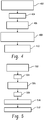
FIGURE 4 illustrates an example method. -
FIGURE 5 illustrates another example method. -
FIGURE 1 illustrates a computed tomography (CT)scanner 100 that includes astationary gantry 102 and a rotatinggantry 104, which is rotatably supported by thestationary gantry 102. The rotatinggantry 104 rotates around anexamination region 106 about a longitudinal or z-axis 108. Aradiation source 110, such as an x-ray tube, is supported by and rotates with the rotatinggantry 104 around theexamination region 106 and emits polychromatic radiation. Acollimator 112 collimates the emitted radiation to produce a generally fan, wedge, or cone shaped radiation beam that traverses theexamination region 106. A radiationsensitive detector array 118 detects photons that traverse theexamination region 106 and generates projection data indicative the examination region. - An
injector 114 is configured to inject or administer a contrast medium in the patient for a scan. As described in greater detail below, in one instance the injector is used to concurrently administer at least two different contrast agents (e.g., a contrast agent containing gadolinium or iodine, etc.) with two different spectral properties in a same vessel or in different vessels. In another instance, the injector is used to successively administer two or more different contrast agents with a delay between the administering. Amodulator 116 provides a control signal indicative of the injection pattern or profile of the two or more different contrast agents, including the concentrations of the two or more different contrast agents over time. The contrast agents can alternatively be manually administered by a clinician or the like. - A
reconstructor 120 reconstructs the projection data and generates volumetric image data indicative thereof. In one instance, thereconstructor 120 employs a spectral algorithm 124 such as a K-edge algorithm. Such an algorithm allows for selective and quantitative imaging of materials with different spectral properties, such as one or more administered contrast agents. Thereconstructor 120 may also employ conventional reconstruction algorithms, for example, a filtered backprojection algorithm or an iterative reconstruction algorithm. - An
image generator 126 processes the volumetric image data and generates one or more images. In one instance, this includes generating at least a first image showing a first contrast agent and a second image showing a second contrast agent. If a tissue specific contrast agent(s) is used, the contrast is substantially absorbed by the tissue and the corresponding image(s) is indicative of the tissue. If a non-tissue specific contrast agent(s) is used, the corresponding image(s) is indicative of the vessels through which the contrast flows. One or more than one of the contrast agents can be specific or non-specific. Theimage generator 126 can also generate other images such as a conventional CT attenuation based image, another image showing another contrast agent, a Compton effect image, a photo-electric effect image, etc. - A patient support 128, such as a couch, supports the patient for the scan. A general
purpose computing system 130 serves as an operator console. Software resident on theconsole 130 allows the operator to control the operation of thesystem 100 such as select imaging protocols including contrast agent based K-edge imaging protocols. As described in greater detail below, one such protocol includes concurrently modulating the administration of two or more different contrast agents during a scan to acquire information about organ perfusion, such as cerebral perfusion, with a time series of spectral CT scans. Another protocol includes successively administering different contrast agents, with a delay therebetween, and performing a scan to concurrently acquire information about different physiological phases in a single scan. - In one embodiment, the
scanner 100 is used to determine a perfusion parameter such as mean transit time (MTT). In one instance, this includes using a combination of concurrently modulating administration of contrast agents and a spectral scan, and determining the MTT based on the modulation technique, the contrast agents, and resulting image data.FIGURE 2 illustrates anMTT determiner 202 that determines an MTT based on an image(s) generated from the image data and the contrast agent concentrations derived from the modulation pattern or profile. - Briefly turning to
FIGURE 3 , example contrast agent modulation profiles are shown. InFIGURE 3 , the y-axis 302 represents the amount (e.g., milliliter per second (ml/sec), etc.) of the contrast agent administered and thex-axis 304 represents time. Afirst profile 306 shows an amount of a first contrast agent as a function of time, and asecond profile 308 shows an amount of a second contrast agent as a function of time. - In this example, the
profiles profiles - Returning to
FIGURE 2 , a suitable example modulation profile or pattern of the contrast agents can be expressed in terms of two contrast agents as shown in modulation function 1:
1 represents the maximal flow rate of the first contrast agent, fl CA2 represents the maximal flow rate of the second contrast agent, CA1 represents the measured concentration of the first contrast agent, and CA2 represents the measured concentration of the second contrast agent. - Based on the modulation profile employed, for any image the measured ratio of the concentrations at any particular image point can be used to calculate an absolute transition time relative to the injection time. That is, a transition time can be determined by determining the time difference between the time when a particular ratio of the concentrations is administered and a point in an image where the ratio of the concentrations is about the same as the particular ratio of concentrations. For instance, the measured ratio at a particular image point or destination can be mapped to the modulation function shown in
FIGURE 3 to determine the corresponding start time of that concentration ratio, and the difference in time represents that transition time. - The above is illustrated in the method of
FIGURE 4 . At 402, at least two different contrast agents having two different spectral properties are concurrently administered to a subject during an imaging procedure, using pre-determined contrast agent administration modulation patterns. At 404, the subject is scanned. At 406, a spectral reconstruction is performed on the resulting projection data, which is indicative of the at least two different contrast agents. At 408, the concentrations of the at least two different contrast agents are determined for a particular image point based on the spectral reconstruction. At 410, the MTT determiner determines an MTT for the particular image point based on a ratio of the concentrations and the contrast modulation patterns. - In another embodiment, the
scanner 100 is used for multi-phase study such as a multi-phase liver study. Such studies can be used to identify hyper or hypo perfused regions (HCC or metastases) during the aortic phase, the portal venous phase and/or the equilibrium phase. As noted above, in a conventional study 3 to 5 scans may be performed after the contrast agent is injected in order to capture these phases. In this embodiment, the number of scans may be reduced via a suitable injection protocol combined with a spectral CT separation of the injected contrast agents. - An example is provided in
FIGURE 5 . At 502, a first contrast agent is administered for a first pre-set period of time. In one instance, the first pre-set period of time is ten (10) seconds. At 504, the next administration of a contrast agent is delayed by a second pre-set period of time. In one instance, the second pre-set period of time is ten (10) seconds. At 506, a second contrast agent is administered for a third pre-set period of time. In one instance, the third pre-set period of time is five (5) seconds. If another contrast agent is to be administered, it may also be delayed another pre-set time period. At 508, scanning is delayed by a fourth pre-set period of time. In one instance, the fourth pre-set period of time is ten (10) seconds. - At 510, a spectral CT scan is performed. Using the above protocol or other suitable protocol, during the scan the first contrast agent will be in the portal venous phase when the second contrast agent is in the aortic phase. The selective imaging capabilities of spectral CT allows the separation between the first and second contrast agents. At 512, two contrast images for two of the venous and the aortic are generated. As such, two contrast images for two of the phases can be captured in a single scan. When three or more contrast agents are administered, three or more images for the three phases are captured in a single scan.
- In the above embodiments, two or more contrast agents are concurrently administered in the same vessel or successively administered in the same vessel. It is to be appreciated that administration of the contrast agents can alternatively be in different vessels. For example, the contrast agents can be administered at different injection points (left and right hemisphere, front and back lobe, etc.). Another application of this technique is to solve the inverse problem of a complex pharmacokinetic model. In other words, the free parameter of a pharmacokinetic model can be numerically determined with a proper multi contrast agent modulated injection protocol and selective imaging of the used contrast agents.
- It is to be appreciated that other procedure and phases are also contemplated herein, including essentially any procedure involving tracking contrast flow through different phases is contemplated herein. For such procedure, a single scan can be performed to capture contrast in one or more of the different phases. Examples of other suitable phases include, but are not limited to, arterial, pancreatic, hepatic, liver, etc. phases.
- As noted above, the
reconstructor 120 can employ a K-edge algorithm. The following illustrates an example algorithm for two K-edge substances, such as the two contrast agents in the examples herein. Generally, theradiation source 110 emits polychromatic radiation with an emission spectrum T(E). The detection signal of the i-th detector channel is indicated by di and can be described by Equation 1:
- The input to the
image generator 126 includes the energy-resolved detection signals di for a plurality, e.g., four (4), energy bins. The emission spectrum T(E) and spectral sensitivity Di(E) generally are known. The absorption spectra P(E), C(E), K1 (E) and K2 (E) are known. Since the energy dependent functions and the detection signals di are known and since at least four detection signals d 1-d 4 are available for at least four energy bins b 1-b 4, a system of at least four equations is formed having four unknowns which can thus be solved with known mathematical methods. If more than four energy bins are available, it is preferred to use a maximum likelihood approach that takes the noise statistics of the measurements into account. - The resulting density length products ρ k-edge1 and ρ k-edge2 are the first substance contribution and the second substance contribution, respectively, which can be used to generate a first K-edge image for the first substance and a second K-edge image for the second substance. In addition, the photo-electric density length product ρ photo can be used to reconstruct a photo-electric image, and the Compton effect density length product ρ compton can be used to reconstruct a Compton effect image. Generally, the Compton effect image and the photo-electric effect image show the object itself. These four images can be shown one by one, or they can be mixed, for example, a final image can show the first substance, the second substance and the Compton effect image and/or the photo-electric effect image. It is also possible to reconstruct one image showing one, some or all of the four components.
- It is to be understood that the spectral decomposition can be performed on projection data or in the image domain.
- Although the above is explained relatvie to particular applications, it is to be appreciated that the embodiments can be used to determine other parameters related to perfursion such, but not limited to, blood flow, blood volume, and/or other perfusion parameters.
- The invention has been described herein with reference to the various embodiments. Modifications and alterations may occur to others upon reading the description herein. It is intended that the invention be construed as including all such modifications and alterations insofar as they come within the scope of the appended claims.
Claims (10)
- A system, comprising:a radiation source (110) configured to rotate about an examination region and emit polychromatic radiation that traverses the examination region;a detector array (118), located across from the radiation source (110) opposite the examination region, configured to detect radiation traversing the examination region and generate a signal indicative thereof;an injector (114) configured to administer at least two different contrast agents for an imaging procedure based on a contrast agent amount modulation profile; anda reconstructor (120) configured to spectrally reconstruct the signal to generate first image data of the first contrast agent and second image data of the second contrast agent;
characterised in that the system further comprisesa mean transit time determiner (202) configured to determine a mean transit time based on the first and second image data and first and second contrast agent concentration derived from the contrast agent modulation profile. - The system of claim 1, wherein the injector (114) is configured to concurrently administer the at least two contrast agents based on different modulation patterns.
- The system of claim 2, wherein the modulation profile is one of triangular, saw tooth, or sinusoidal.
- The system of any one of claims 1 to 3, wherein the injector is configured to substantially continuously vary an amount of each contrast agent with respect to time.
- The system of any one of claims 1 to 4, wherein the injector is configured to administer the at least two different contrast agents such that an aggregate amount of the contrast agents is substantially constant over time.
- The system of any one of claims 1 to 5, wherein the modulation profiles of the first and second contrast agents are inversely proportional.
- The system of any of claims 1 or 2, wherein the reconstructor (120) decomposes the signal into components, including but not limited to, at least a first K-edge component and a second K-edge component, and the first image is based on the first K-edge component and the second image is based on the second K-edge component.
- The system of any of claims 1 to 3, further including a modulator (116) configured to determine and provide the modulation profile.
- The system of any of claims 1 to 8, wherein the mean transit time determiner (202) determines the mean transit time for a particular image point based on a ratio of the concentrations and the contrast modulation patterns.
- The system of claim 9, wherein the mean transit time is an absolute transition time relative to the injection time.
Applications Claiming Priority (2)
| Application Number | Priority Date | Filing Date | Title |
|---|---|---|---|
| US8175208P | 2008-07-18 | 2008-07-18 | |
| PCT/IB2009/052672 WO2010007545A1 (en) | 2008-07-18 | 2009-06-22 | Spectral imaging |
Publications (2)
| Publication Number | Publication Date |
|---|---|
| EP2303125A1 EP2303125A1 (en) | 2011-04-06 |
| EP2303125B1 true EP2303125B1 (en) | 2019-10-30 |
Family
ID=40947944
Family Applications (1)
| Application Number | Title | Priority Date | Filing Date |
|---|---|---|---|
| EP09786439.1A Active EP2303125B1 (en) | 2008-07-18 | 2009-06-22 | Spectral imaging |
Country Status (5)
| Country | Link |
|---|---|
| US (1) | US9055919B2 (en) |
| EP (1) | EP2303125B1 (en) |
| JP (1) | JP5539342B2 (en) |
| CN (1) | CN102098963B (en) |
| WO (1) | WO2010007545A1 (en) |
Families Citing this family (17)
| Publication number | Priority date | Publication date | Assignee | Title |
|---|---|---|---|---|
| WO2012046157A1 (en) * | 2010-10-05 | 2012-04-12 | Koninklijke Philips Electronics N.V. | Apparatus and method for locating magnetic particles |
| US9928585B2 (en) * | 2011-01-27 | 2018-03-27 | Koninklijke Philips N.V. | Spectral imaging |
| EP2844147B1 (en) * | 2012-05-02 | 2018-06-20 | Koninklijke Philips N.V. | Spectral ct visualization of imageable drug eluting beads |
| DE102012222714A1 (en) * | 2012-12-11 | 2014-06-12 | Siemens Aktiengesellschaft | Determination of a multiple energy image |
| JP2015033578A (en) | 2013-07-11 | 2015-02-19 | 株式会社東芝 | X-ray ct apparatus, x-ray ct system and injector |
| KR101725099B1 (en) * | 2014-12-05 | 2017-04-26 | 삼성전자주식회사 | Computed tomography apparatus and control method for the same |
| JP2018513715A (en) * | 2015-03-18 | 2018-05-31 | コーニンクレッカ フィリップス エヌ ヴェKoninklijke Philips N.V. | Determination of drug concentration after hepatic artery chemoembolization with differently sized drug-eluting microsphere beads |
| US10383590B2 (en) * | 2015-09-28 | 2019-08-20 | General Electric Company | Methods and systems for adaptive scan control |
| JP6619890B2 (en) * | 2015-11-10 | 2019-12-11 | コーニンクレッカ フィリップス エヌ ヴェKoninklijke Philips N.V. | Computed tomography method |
| CN107530037B (en) * | 2015-12-17 | 2018-11-27 | 皇家飞利浦有限公司 | Method for generating contrast medium concentrations figure |
| CN109414236A (en) * | 2016-07-06 | 2019-03-01 | 皇家飞利浦有限公司 | For providing the system for being used for inner hexagon image |
| DE102016222093A1 (en) * | 2016-11-10 | 2017-12-28 | Siemens Healthcare Gmbh | Simultaneous use of different contrast agents in CT imaging procedures |
| CN106923856B (en) * | 2017-04-14 | 2020-05-22 | 郑州大学第一附属医院 | Image processing method for simultaneously realizing CT perfusion and energy spectrum liver scanning |
| EP3672688B1 (en) * | 2017-08-23 | 2023-03-01 | Siemens Healthcare GmbH | Method for providing result data which is suitable for use in planning the irradiation of a patient |
| US20190370956A1 (en) * | 2018-05-30 | 2019-12-05 | General Electric Company | Contrast imaging system and method |
| EP3795080B1 (en) * | 2019-09-19 | 2023-01-11 | Siemens Healthcare GmbH | Contrast media based time coding in x-ray imaging |
| DE102020206729A1 (en) | 2020-05-28 | 2021-12-02 | Siemens Healthcare Gmbh | Motion correction procedure |
Family Cites Families (25)
| Publication number | Priority date | Publication date | Assignee | Title |
|---|---|---|---|---|
| US4859450A (en) * | 1984-08-13 | 1989-08-22 | The General Hospital Corporation | Method of NMR imaging using antibody to cardiac myosin |
| US6365183B1 (en) * | 1998-05-07 | 2002-04-02 | Alza Corporation | Method of fabricating a banded prolonged release active agent dosage form |
| EP1105162A1 (en) * | 1998-08-10 | 2001-06-13 | Bracco Research S.A. | Combination of a positive mri contrast agent with a negative mri contrast agent |
| US6645147B1 (en) * | 1998-11-25 | 2003-11-11 | Acuson Corporation | Diagnostic medical ultrasound image and system for contrast agent imaging |
| DE19859811C2 (en) * | 1998-12-23 | 2001-05-10 | Hilekes Guido | Contrast agent injection system |
| WO2001008552A1 (en) * | 1999-08-03 | 2001-02-08 | Biophysica, Llc | Spectroscopic systems and methods for detecting tissue properties |
| US6804546B1 (en) * | 2001-04-20 | 2004-10-12 | Koninklijke Philips Electronics, N.V. | Multiple contrast echo-planar imaging for contrast-enhanced imaging |
| US20030050555A1 (en) * | 2001-04-30 | 2003-03-13 | Critchlow Richard G. | MR injector system with increased mobility and electromagnetic interference mitigation |
| JP3878176B2 (en) * | 2001-11-12 | 2007-02-07 | ウイスコンシン アラムナイ リサーチ フオンデーシヨン | Three-dimensional phase contrast magnetic resonance imaging using interleaved projection-reconstruction data |
| US6745066B1 (en) * | 2001-11-21 | 2004-06-01 | Koninklijke Philips Electronics, N.V. | Measurements with CT perfusion |
| US7627078B2 (en) * | 2002-11-08 | 2009-12-01 | Ge Medical Systems Global Technology Company, Llc | Methods and apparatus for detecting structural, perfusion, and functional abnormalities |
| US6813333B2 (en) * | 2002-11-27 | 2004-11-02 | Ge Medical Systems Global Technology Company, Llc | Methods and apparatus for detecting structural, perfusion, and functional abnormalities |
| US20040101088A1 (en) * | 2002-11-27 | 2004-05-27 | Sabol John Michael | Methods and apparatus for discriminating multiple contrast agents |
| US6950492B2 (en) * | 2003-06-25 | 2005-09-27 | Besson Guy M | Dynamic multi-spectral X-ray projection imaging |
| ATE476724T1 (en) * | 2003-12-19 | 2010-08-15 | Koninkl Philips Electronics Nv | METHOD FOR THE COMPUTER-ASSISTED VISUALIZATION OF DIAGNOSTIC IMAGE DATA |
| EP1756742A2 (en) * | 2004-05-28 | 2007-02-28 | Philips Intellectual Property & Standards GmbH | System for the noninvasive determination of tracer concentration in blood |
| US20060036167A1 (en) * | 2004-07-03 | 2006-02-16 | Shina Systems Ltd. | Vascular image processing |
| US20080253503A1 (en) | 2005-09-22 | 2008-10-16 | Koninklijke Philips Electronics N. V. | Ct-Imaging System |
| US8208699B2 (en) | 2005-10-05 | 2012-06-26 | Koninklijke Philips Electronics N.V. | Method and apparatus for predicting enhancement in angiography |
| DE102006009222B4 (en) * | 2006-02-28 | 2008-02-28 | Siemens Ag | Method and device for determining the concentration of a substance in a body material by means of multi-energy computed tomography |
| JP2009535126A (en) * | 2006-04-27 | 2009-10-01 | バーンズ−ジューイッシュ ホスピタル | Target tissue detection and imaging |
| US7756239B2 (en) * | 2006-12-07 | 2010-07-13 | General Electric Company | Diagnostic imaging two non K-edge basis materials plus N K-edge contrast agents |
| EP2097835B1 (en) * | 2006-12-29 | 2018-05-30 | Bayer Healthcare LLC | Patient-based parameter generation systems for medical injection procedures |
| US20080208068A1 (en) * | 2007-02-26 | 2008-08-28 | Timothy Robertson | Dynamic positional information constrained heart model |
| US20090052621A1 (en) * | 2007-08-23 | 2009-02-26 | Deborah Joy Walter | Method and apparatus for basis material decomposition with k-edge materials |
-
2009
- 2009-06-22 JP JP2011518036A patent/JP5539342B2/en active Active
- 2009-06-22 EP EP09786439.1A patent/EP2303125B1/en active Active
- 2009-06-22 WO PCT/IB2009/052672 patent/WO2010007545A1/en active Application Filing
- 2009-06-22 US US13/000,384 patent/US9055919B2/en active Active
- 2009-06-22 CN CN200980127987.0A patent/CN102098963B/en active Active
Non-Patent Citations (1)
| Title |
|---|
| None * |
Also Published As
| Publication number | Publication date |
|---|---|
| JP5539342B2 (en) | 2014-07-02 |
| WO2010007545A1 (en) | 2010-01-21 |
| US9055919B2 (en) | 2015-06-16 |
| EP2303125A1 (en) | 2011-04-06 |
| US20110097273A1 (en) | 2011-04-28 |
| CN102098963A (en) | 2011-06-15 |
| CN102098963B (en) | 2014-03-26 |
| JP2011528248A (en) | 2011-11-17 |
Similar Documents
| Publication | Publication Date | Title |
|---|---|---|
| EP2303125B1 (en) | Spectral imaging | |
| Lee et al. | Computed body tomography with MRI correlation | |
| Fleischmann et al. | Optimal vascular and parenchymal contrast enhancement: the current state of the art | |
| EP2429403B1 (en) | Perfusion imaging | |
| Hartman et al. | Applications of dual-energy CT in urologic imaging: an update | |
| JP5363572B2 (en) | Spectral X-ray imaging system and method | |
| US9955934B2 (en) | Dynamic acquisition sampling rate for computed tomography perfusion (CTP) imaging | |
| Saini | Multi–detector row CT: principles and practice for abdominal applications | |
| Kim et al. | Adenosine-stress dynamic myocardial perfusion imaging using 128-slice dual-source CT: optimization of the CT protocol to reduce the radiation dose | |
| Stehli et al. | Impact of monochromatic coronary computed tomography angiography from single-source dual-energy CT on coronary stenosis quantification | |
| Müller et al. | Interventional dual‐energy imaging—Feasibility of rapid kV‐switching on a C‐arm CT system | |
| Christensen et al. | Effects of iopamidol-370 versus iodixanol-320 on coronary contrast, branch depiction, and heart rate variability in dual-source coronary MDCT angiography | |
| JP5820549B2 (en) | Perfusion imaging | |
| US11406339B2 (en) | System and method for determining vascular velocity using medical imaging | |
| WO2008078231A1 (en) | Imaging system for imaging substances present in an object of interest | |
| Knobloch et al. | Dual-energy computed tomography for the assessment of early treatment effects of regorafenib in a preclinical tumor model: comparison with dynamic contrast-enhanced CT and conventional contrast-enhanced single-energy CT | |
| Chatzizisis et al. | Accuracy and reproducibility of automated, standardized coronary transluminal attenuation gradient measurements | |
| Wu et al. | Left ventricular functional analysis using 64-slice multidetector row computed tomography: comparison with left ventriculography and cardiovascular magnetic resonance | |
| US20170014069A1 (en) | Spectral imaging based fluid volume map | |
| FI104042B (en) | Procedure for measuring lung perfusion | |
| EP2501287B1 (en) | Functional imaging | |
| Taguchi | Imaging Technologies and Potential Clinical Applications of Photon Counting X-Ray Computed Tomography | |
| Territo et al. | Measurement of cardiovascular function using a novel view-sharing PET reconstruction method and tracer kinetic analysis | |
| Kang et al. | Evaluation of Myocardial Ischemia Using Perfusion Study | |
| Ko | CT Evaluation of the Myocardial Blood Supply: Dual-Source Dual-Energy CT |
Legal Events
| Date | Code | Title | Description |
|---|---|---|---|
| PUAI | Public reference made under article 153(3) epc to a published international application that has entered the european phase |
Free format text: ORIGINAL CODE: 0009012 |
|
| 17P | Request for examination filed |
Effective date: 20110218 |
|
| AK | Designated contracting states |
Kind code of ref document: A1 Designated state(s): AT BE BG CH CY CZ DE DK EE ES FI FR GB GR HR HU IE IS IT LI LT LU LV MC MK MT NL NO PL PT RO SE SI SK TR |
|
| AX | Request for extension of the european patent |
Extension state: AL BA RS |
|
| DAX | Request for extension of the european patent (deleted) | ||
| RAP1 | Party data changed (applicant data changed or rights of an application transferred) |
Owner name: KONINKLIJKE PHILIPS N.V. Owner name: PHILIPS INTELLECTUAL PROPERTY & STANDARDS GMBH |
|
| 17Q | First examination report despatched |
Effective date: 20140924 |
|
| STAA | Information on the status of an ep patent application or granted ep patent |
Free format text: STATUS: EXAMINATION IS IN PROGRESS |
|
| GRAP | Despatch of communication of intention to grant a patent |
Free format text: ORIGINAL CODE: EPIDOSNIGR1 |
|
| STAA | Information on the status of an ep patent application or granted ep patent |
Free format text: STATUS: GRANT OF PATENT IS INTENDED |
|
| RIC1 | Information provided on ipc code assigned before grant |
Ipc: A61M 5/00 20060101ALI20190425BHEP Ipc: A61K 49/00 20060101ALI20190425BHEP Ipc: A61B 5/00 20060101ALI20190425BHEP Ipc: A61B 6/00 20060101AFI20190425BHEP Ipc: A61B 6/03 20060101ALI20190425BHEP |
|
| INTG | Intention to grant announced |
Effective date: 20190515 |
|
| GRAS | Grant fee paid |
Free format text: ORIGINAL CODE: EPIDOSNIGR3 |
|
| GRAA | (expected) grant |
Free format text: ORIGINAL CODE: 0009210 |
|
| STAA | Information on the status of an ep patent application or granted ep patent |
Free format text: STATUS: THE PATENT HAS BEEN GRANTED |
|
| AK | Designated contracting states |
Kind code of ref document: B1 Designated state(s): AT BE BG CH CY CZ DE DK EE ES FI FR GB GR HR HU IE IS IT LI LT LU LV MC MK MT NL NO PL PT RO SE SI SK TR |
|
| REG | Reference to a national code |
Ref country code: GB Ref legal event code: FG4D |
|
| REG | Reference to a national code |
Ref country code: CH Ref legal event code: EP |
|
| REG | Reference to a national code |
Ref country code: AT Ref legal event code: REF Ref document number: 1195292 Country of ref document: AT Kind code of ref document: T Effective date: 20191115 |
|
| REG | Reference to a national code |
Ref country code: DE Ref legal event code: R096 Ref document number: 602009060297 Country of ref document: DE |
|
| REG | Reference to a national code |
Ref country code: IE Ref legal event code: FG4D |
|
| REG | Reference to a national code |
Ref country code: DE Ref legal event code: R084 Ref document number: 602009060297 Country of ref document: DE |
|
| REG | Reference to a national code |
Ref country code: GB Ref legal event code: 746 Effective date: 20200107 |
|
| REG | Reference to a national code |
Ref country code: LT Ref legal event code: MG4D |
|
| RAP2 | Party data changed (patent owner data changed or rights of a patent transferred) |
Owner name: PHILIPS INTELLECTUAL PROPERTY & STANDARDS GMBH Owner name: KONINKLIJKE PHILIPS N.V. |
|
| PG25 | Lapsed in a contracting state [announced via postgrant information from national office to epo] |
Ref country code: NO Free format text: LAPSE BECAUSE OF FAILURE TO SUBMIT A TRANSLATION OF THE DESCRIPTION OR TO PAY THE FEE WITHIN THE PRESCRIBED TIME-LIMIT Effective date: 20200130 Ref country code: LT Free format text: LAPSE BECAUSE OF FAILURE TO SUBMIT A TRANSLATION OF THE DESCRIPTION OR TO PAY THE FEE WITHIN THE PRESCRIBED TIME-LIMIT Effective date: 20191030 Ref country code: PL Free format text: LAPSE BECAUSE OF FAILURE TO SUBMIT A TRANSLATION OF THE DESCRIPTION OR TO PAY THE FEE WITHIN THE PRESCRIBED TIME-LIMIT Effective date: 20191030 Ref country code: GR Free format text: LAPSE BECAUSE OF FAILURE TO SUBMIT A TRANSLATION OF THE DESCRIPTION OR TO PAY THE FEE WITHIN THE PRESCRIBED TIME-LIMIT Effective date: 20200131 Ref country code: ES Free format text: LAPSE BECAUSE OF FAILURE TO SUBMIT A TRANSLATION OF THE DESCRIPTION OR TO PAY THE FEE WITHIN THE PRESCRIBED TIME-LIMIT Effective date: 20191030 Ref country code: NL Free format text: LAPSE BECAUSE OF FAILURE TO SUBMIT A TRANSLATION OF THE DESCRIPTION OR TO PAY THE FEE WITHIN THE PRESCRIBED TIME-LIMIT Effective date: 20191030 Ref country code: PT Free format text: LAPSE BECAUSE OF FAILURE TO SUBMIT A TRANSLATION OF THE DESCRIPTION OR TO PAY THE FEE WITHIN THE PRESCRIBED TIME-LIMIT Effective date: 20200302 Ref country code: LV Free format text: LAPSE BECAUSE OF FAILURE TO SUBMIT A TRANSLATION OF THE DESCRIPTION OR TO PAY THE FEE WITHIN THE PRESCRIBED TIME-LIMIT Effective date: 20191030 Ref country code: SE Free format text: LAPSE BECAUSE OF FAILURE TO SUBMIT A TRANSLATION OF THE DESCRIPTION OR TO PAY THE FEE WITHIN THE PRESCRIBED TIME-LIMIT Effective date: 20191030 Ref country code: FI Free format text: LAPSE BECAUSE OF FAILURE TO SUBMIT A TRANSLATION OF THE DESCRIPTION OR TO PAY THE FEE WITHIN THE PRESCRIBED TIME-LIMIT Effective date: 20191030 Ref country code: BG Free format text: LAPSE BECAUSE OF FAILURE TO SUBMIT A TRANSLATION OF THE DESCRIPTION OR TO PAY THE FEE WITHIN THE PRESCRIBED TIME-LIMIT Effective date: 20200130 |
|
| REG | Reference to a national code |
Ref country code: NL Ref legal event code: MP Effective date: 20191030 |
|
| PG25 | Lapsed in a contracting state [announced via postgrant information from national office to epo] |
Ref country code: IS Free format text: LAPSE BECAUSE OF FAILURE TO SUBMIT A TRANSLATION OF THE DESCRIPTION OR TO PAY THE FEE WITHIN THE PRESCRIBED TIME-LIMIT Effective date: 20200229 Ref country code: HR Free format text: LAPSE BECAUSE OF FAILURE TO SUBMIT A TRANSLATION OF THE DESCRIPTION OR TO PAY THE FEE WITHIN THE PRESCRIBED TIME-LIMIT Effective date: 20191030 |
|
| PG25 | Lapsed in a contracting state [announced via postgrant information from national office to epo] |
Ref country code: CZ Free format text: LAPSE BECAUSE OF FAILURE TO SUBMIT A TRANSLATION OF THE DESCRIPTION OR TO PAY THE FEE WITHIN THE PRESCRIBED TIME-LIMIT Effective date: 20191030 Ref country code: DK Free format text: LAPSE BECAUSE OF FAILURE TO SUBMIT A TRANSLATION OF THE DESCRIPTION OR TO PAY THE FEE WITHIN THE PRESCRIBED TIME-LIMIT Effective date: 20191030 Ref country code: RO Free format text: LAPSE BECAUSE OF FAILURE TO SUBMIT A TRANSLATION OF THE DESCRIPTION OR TO PAY THE FEE WITHIN THE PRESCRIBED TIME-LIMIT Effective date: 20191030 Ref country code: EE Free format text: LAPSE BECAUSE OF FAILURE TO SUBMIT A TRANSLATION OF THE DESCRIPTION OR TO PAY THE FEE WITHIN THE PRESCRIBED TIME-LIMIT Effective date: 20191030 |
|
| REG | Reference to a national code |
Ref country code: DE Ref legal event code: R097 Ref document number: 602009060297 Country of ref document: DE |
|
| REG | Reference to a national code |
Ref country code: AT Ref legal event code: MK05 Ref document number: 1195292 Country of ref document: AT Kind code of ref document: T Effective date: 20191030 |
|
| PG25 | Lapsed in a contracting state [announced via postgrant information from national office to epo] |
Ref country code: SK Free format text: LAPSE BECAUSE OF FAILURE TO SUBMIT A TRANSLATION OF THE DESCRIPTION OR TO PAY THE FEE WITHIN THE PRESCRIBED TIME-LIMIT Effective date: 20191030 Ref country code: IT Free format text: LAPSE BECAUSE OF FAILURE TO SUBMIT A TRANSLATION OF THE DESCRIPTION OR TO PAY THE FEE WITHIN THE PRESCRIBED TIME-LIMIT Effective date: 20191030 |
|
| PLBE | No opposition filed within time limit |
Free format text: ORIGINAL CODE: 0009261 |
|
| STAA | Information on the status of an ep patent application or granted ep patent |
Free format text: STATUS: NO OPPOSITION FILED WITHIN TIME LIMIT |
|
| 26N | No opposition filed |
Effective date: 20200731 |
|
| PG25 | Lapsed in a contracting state [announced via postgrant information from national office to epo] |
Ref country code: AT Free format text: LAPSE BECAUSE OF FAILURE TO SUBMIT A TRANSLATION OF THE DESCRIPTION OR TO PAY THE FEE WITHIN THE PRESCRIBED TIME-LIMIT Effective date: 20191030 Ref country code: SI Free format text: LAPSE BECAUSE OF FAILURE TO SUBMIT A TRANSLATION OF THE DESCRIPTION OR TO PAY THE FEE WITHIN THE PRESCRIBED TIME-LIMIT Effective date: 20191030 |
|
| REG | Reference to a national code |
Ref country code: DE Ref legal event code: R081 Ref document number: 602009060297 Country of ref document: DE Owner name: PHILIPS GMBH, DE Free format text: FORMER OWNER: PHILIPS INTELLECTUAL PROPERTY & STANDARDS GMBH, 20099 HAMBURG, DE |
|
| PG25 | Lapsed in a contracting state [announced via postgrant information from national office to epo] |
Ref country code: MC Free format text: LAPSE BECAUSE OF FAILURE TO SUBMIT A TRANSLATION OF THE DESCRIPTION OR TO PAY THE FEE WITHIN THE PRESCRIBED TIME-LIMIT Effective date: 20191030 |
|
| REG | Reference to a national code |
Ref country code: CH Ref legal event code: PL |
|
| PG25 | Lapsed in a contracting state [announced via postgrant information from national office to epo] |
Ref country code: LU Free format text: LAPSE BECAUSE OF NON-PAYMENT OF DUE FEES Effective date: 20200622 |
|
| REG | Reference to a national code |
Ref country code: BE Ref legal event code: MM Effective date: 20200630 |
|
| PG25 | Lapsed in a contracting state [announced via postgrant information from national office to epo] |
Ref country code: LI Free format text: LAPSE BECAUSE OF NON-PAYMENT OF DUE FEES Effective date: 20200630 Ref country code: IE Free format text: LAPSE BECAUSE OF NON-PAYMENT OF DUE FEES Effective date: 20200622 Ref country code: CH Free format text: LAPSE BECAUSE OF NON-PAYMENT OF DUE FEES Effective date: 20200630 |
|
| PG25 | Lapsed in a contracting state [announced via postgrant information from national office to epo] |
Ref country code: BE Free format text: LAPSE BECAUSE OF NON-PAYMENT OF DUE FEES Effective date: 20200630 |
|
| PG25 | Lapsed in a contracting state [announced via postgrant information from national office to epo] |
Ref country code: TR Free format text: LAPSE BECAUSE OF FAILURE TO SUBMIT A TRANSLATION OF THE DESCRIPTION OR TO PAY THE FEE WITHIN THE PRESCRIBED TIME-LIMIT Effective date: 20191030 Ref country code: MT Free format text: LAPSE BECAUSE OF FAILURE TO SUBMIT A TRANSLATION OF THE DESCRIPTION OR TO PAY THE FEE WITHIN THE PRESCRIBED TIME-LIMIT Effective date: 20191030 Ref country code: CY Free format text: LAPSE BECAUSE OF FAILURE TO SUBMIT A TRANSLATION OF THE DESCRIPTION OR TO PAY THE FEE WITHIN THE PRESCRIBED TIME-LIMIT Effective date: 20191030 |
|
| PG25 | Lapsed in a contracting state [announced via postgrant information from national office to epo] |
Ref country code: MK Free format text: LAPSE BECAUSE OF FAILURE TO SUBMIT A TRANSLATION OF THE DESCRIPTION OR TO PAY THE FEE WITHIN THE PRESCRIBED TIME-LIMIT Effective date: 20191030 |
|
| PGFP | Annual fee paid to national office [announced via postgrant information from national office to epo] |
Ref country code: FR Payment date: 20230622 Year of fee payment: 15 Ref country code: DE Payment date: 20230627 Year of fee payment: 15 |
|
| PGFP | Annual fee paid to national office [announced via postgrant information from national office to epo] |
Ref country code: GB Payment date: 20230620 Year of fee payment: 15 |