EP2302745A1 - Electrical connector assembly - Google Patents
Electrical connector assembly Download PDFInfo
- Publication number
- EP2302745A1 EP2302745A1 EP10177606A EP10177606A EP2302745A1 EP 2302745 A1 EP2302745 A1 EP 2302745A1 EP 10177606 A EP10177606 A EP 10177606A EP 10177606 A EP10177606 A EP 10177606A EP 2302745 A1 EP2302745 A1 EP 2302745A1
- Authority
- EP
- European Patent Office
- Prior art keywords
- latch
- base
- towers
- contact
- flanges
- Prior art date
- Legal status (The legal status is an assumption and is not a legal conclusion. Google has not performed a legal analysis and makes no representation as to the accuracy of the status listed.)
- Granted
Links
Images


Classifications
-
- H—ELECTRICITY
- H01—ELECTRIC ELEMENTS
- H01R—ELECTRICALLY-CONDUCTIVE CONNECTIONS; STRUCTURAL ASSOCIATIONS OF A PLURALITY OF MUTUALLY-INSULATED ELECTRICAL CONNECTING ELEMENTS; COUPLING DEVICES; CURRENT COLLECTORS
- H01R13/00—Details of coupling devices of the kinds covered by groups H01R12/70 or H01R24/00 - H01R33/00
- H01R13/64—Means for preventing incorrect coupling
- H01R13/645—Means for preventing incorrect coupling by exchangeable elements on case or base
- H01R13/6456—Means for preventing incorrect coupling by exchangeable elements on case or base comprising keying elements at different positions along the periphery of the connector
-
- H—ELECTRICITY
- H01—ELECTRIC ELEMENTS
- H01R—ELECTRICALLY-CONDUCTIVE CONNECTIONS; STRUCTURAL ASSOCIATIONS OF A PLURALITY OF MUTUALLY-INSULATED ELECTRICAL CONNECTING ELEMENTS; COUPLING DEVICES; CURRENT COLLECTORS
- H01R13/00—Details of coupling devices of the kinds covered by groups H01R12/70 or H01R24/00 - H01R33/00
- H01R13/62—Means for facilitating engagement or disengagement of coupling parts or for holding them in engagement
- H01R13/627—Snap or like fastening
- H01R13/6271—Latching means integral with the housing
- H01R13/6272—Latching means integral with the housing comprising a single latching arm
Abstract
Description
- The subject matter herein relates generally to electrical connector assemblies, and more particularly, to electrical connector assemblies having mating features.
- Electrical connector assemblies typically include mating halves that are mated together. Electrical connector assemblies are used in a variety of industries and applications, such as in the appliance industry in a refrigerator. Other examples include in the automotive industry, the machinery industry, cabling networks, and the like. The mating halves are typically terminated to ends of cables and include contacts that are mated together to make an electrical connection between the mating halves.
- One problem with known connector assemblies is difficulty in mating the mating halves and/or damage to the various components during mating. For example, the contacts may be damaged if the mating halves are not properly aligned during mating. Additionally, in some applications, it may be difficult for the user to make the connection as the connector assembly may be positioned in an area that is difficult to reach or see the mating halves during mating. It is also difficult to grip the connector assemblies during mating and unmating.
- Another problem with known connector assemblies is that the latches that are provided on one or both connector halves may be snagged by the wires that are associated with the connector assemblies. For example, during shipping of the cabled assemblies, the wires may wrap around or get snagged underneath the latch. When handling the connector assemblies, pulling on the wires may cause the latch to bend and/or break.
- The problem to be solved is a need for an electrical connector assembly that overcomes these and other problems. An electrical connector assembly is needed that may be assembled in a convenient manner. An electrical connector assembly is needed that reduces or eliminates the problems associated with wire snag of the latch.
- The solution to the problem is provided by an electrical connector assembly that includes a housing having a base and contact towers extending forward from the base. The base has an outer perimeter defined between a front and a rear of the base, and the base has a latch extending forward from the base generally parallel to and spaced apart from the towers such that a gap is defined between a bottom of the latch and a top of the towers. Flanges extend upward from the top of the towers and at least partially block the gap. Contacts are held by the housing, where the contacts extend into the contact towers for mating with mating contacts of a mating connector.
- Furthermore, an electrical connector assembly is provided that includes a housing having a base and contact towers extending forward from the base. The base has an outer perimeter defined between a front and a rear of the base, and the base has a latch extending forward from the base for latching engagement with a mating connector. The base has a first finger grip and a second finger grip. The first finger grip is tapered in a forward direction and the second finger grip is tapered in a rearward direction. Contacts are held by the housing, where the contacts extend into the contact towers for mating with mating contacts of the mating connector.
- In addition, an electrical connector assembly is provided including a plug connector and a mating connector. The plug connector includes a housing having a base and contact towers extending forward from the base. The base receives contacts therein that extend at least partially into the contact towers. The base has an outer perimeter defined between a front and a rear of the base, and the base has a latch extending forward from the base. The latch is recessed with respect to the outer perimeter of the base. The mating connector includes a housing having contact chambers extending between a front and a rear of the housing. The chambers receive mating contacts therein and the chambers receive the contact towers of the plug connector such that the mating contacts engage the contacts of the plug connector. The housing has a latch cavity receiving the latch of the plug connector such that the latch is contained within the housing of the mating connector.
- The invention will now be described by way of example with reference to the accompanying drawings in which:
-
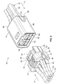
Figure 1 illustrates an electrical connector assembly having a plug connector and a mating connector formed in accordance with an exemplary embodiment. -
Figure 2 illustrates the electrical connector assembly shown inFigure 1 in an unmated state. -
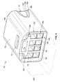
Figure 3 is a front perspective view of the plug connector shown inFigure 1 . -
Figure 4 is a front perspective view of the mating connector shown inFigure 1 . -
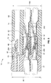
Figure 5 is a cross-sectional view of the electrical connector assembly shown inFigure 1 . -
Figure 1 illustrates anelectrical connector assembly 10 having aplug connector 12 and amating connector 14 formed in accordance with an exemplary embodiment.Figure 2 illustrates theelectrical connector assembly 10 in an unmated state. Theconnectors cables cables individual wires connectors Contacts 24, 26 (shown inFigure 5 ) are terminated to ends of theindividual wires connectors - The
connectors cables connectors connectors connectors connectors connectors connectors - The
plug connector 12 includes ahousing 30 having abase 32 and contact towers 34 (shown inFigure 2 ) extending forward from thebase 32. Thebase 32 extends between afront 36 and a rear 38. Thewires 20 extend rearward from therear 38. Thecontacts 24 and associatedwires 20 may be loaded into thebase 32 through the rear 38. For example, thebase 32 may includecontact cavities 40 that extend entirely through thebase 32 and into thecontact towers 34. Thecontact cavities 40 are separated from one another and receive individual ones of thecontacts 24. Alternatively, thecontact cavities 40 may receive one ormore contacts 24, depending on the particular application. - The
plug connector 12 includes aresilient latch 42 extending forward from thebase 32. Thelatch 42 may be deflectable during mating and unmated with themating connector 14. In the illustrated embodiment, the latch includes aramp surface 44 at a front thereof, and alatching surface 46 behind theramp surface 44. Thelatch 42 is recessed with respect to thebase 32. For example, thelatch 42 does not extend beyond (e.g. above or below) an outer perimeter of thebase 32. - The
plug connector 12 includes afirst finger grip 50 and a pair ofsecond finger grips 52. Any number offinger grips 50 and/or 52 may be provided in alternative embodiments. Thefirst finger grip 50 is provided at thefront 36 of thebase 32. Thesecond finger grips 52 are provided at therear 38 of thebase 32. Thefinger grips base 32. The finger grips 50, 52 provide an area for the user to grip thehousing 30 of theplug connector 12 during mating or unmating. In an exemplary embodiment, thefirst finger grip 50 is tapered in a forward direction and the second finger grips 52 are tapered in a rearward direction. As such, the second finger grips 52 provide a different type of bearing surface for the user to grip thehousing 30 than thefirst finger grip 50. For example, the second finger grips 52 may be configured to allow the user to push theplug connector 12 towards themating connector 14, such as in the direction of the Arrow A, during mating. In contrast, thefirst finger grip 50 may be configured to allow the user to pull theplug connector 12 away from themating connector 14, such as in the direction of Arrow B. In an exemplary embodiment, thefirst finger grip 50 is aligned with thelatch 42. Pushing downward on thefirst finger grip 50 may deflect thelatch 42 so that the user may unlatch thelatch 42, such as during unmating. - The
mating connector 14 includes ahousing 60 having contact chambers 62 (shown inFigure 2 ). Thehousing 60 extends between a front 64 and a rear 66. Thecontact chambers 62 extend entirely through thehousing 60. Thecontacts 26 and associatedwires 22 may be loaded into thehousing 60 through the rear 66. Thewires 22 extend rearward from the rear 66. Thecontact chambers 62 also receive corresponding contact towers 34 of theplug connector 12 such that themating contacts 26 engage thecontacts 24 of theplug connector 12. Thecontact chambers 62 are separated from one another by separatingwalls 68. The separatingwalls 68 are positioned between adjacent contact towers 34 when theplug connector 12 andmating connector 14 are coupled together. - The
mating connector 14 includes alatch cavity 70 that receives thelatch 42 of theplug connector 12 such that thelatch 42 is contained within thehousing 60 of themating connector 14. Thelatch cavity 70 is open at the front 64 and receives thelatch 42 through the open front of thelatch cavity 70. Themating connector 14 also includes awindow 72 that opens through a top 73 of thehousing 60 to thelatch cavity 70. As illustratedFigure 1 , thelatch 42 may be visible within thewindow 72 when theplug connector 12 andmating connector 14 are coupled together. Optionally, thelatch 42 may engage thewindow 72 in a latching engagement. For example, thelatch surface 46 may be received within thewindow 72 and engage one of the walls of thewindow 72 when theplug connector 12 andmating connector 14 are coupled together. - The
mating connector 14 includes a plurality of finger grips 74. Any number of finger grips 74 may be provided. The finger grips 74 are provided at the rear 66 of thehousing 60. The finger grips 74 are recessed with respect to the outer perimeter of thehousing 60. The finger grips 74 provide an area for the user to grip thehousing 60 of themating connector 14 during mating or unmating. The finger grips 74 may be configured to allow the user to push themating connector 14 towards theplug connector 12, such as in the direction of the Arrow C, during mating. -
Figure 3 is a front perspective view of theplug connector 12. Thehousing 30 is manufactured from a dielectric material, such as plastic material. Optionally, thehousing 30 may be formed by an injection molding process using one or more molds that may be separated from thehousing 30 when thehousing 30 is formed. - The
base 32 defines anouter perimeter 80. In an exemplary embodiment, theouter perimeter 80 of thebase 32 is the outermost portion of theplug connector 12. For example, thelatch 42 is recessed with respect to theouter perimeter 80. Additionally, the contact towers 34 are recessed with respect to theouter perimeter 80. As such, theplug connector 12 does not include components that extend outward from thebase 32, which may make theplug connector 12 easier to handle and route through the appliance or device in which theplug connector 12 is used. For example, theplug connector 12 does not include components that could potentially snag on surfaces or through openings as theplug connector 12 is routed into position. - The contact towers 34 extend forward from the
front 36 of thebase 32. The contact towers 34 are rectangular in shape, however the contact towers 34 may have other shapes and alternative embodiment. In the illustrated embodiment, the contact towers 34 are arranged in two rows, anupper row 82 and alower row 84. Four contact towers 34 are included in theupper row 82 and fourcontact towers 34 are included in thelower row 84, thus defining interior contact towers 34 and exterior contact towers 34, with the exterior contact towers 34 flanking the interior contact towers 34. Any number of different tower configurations (e.g. 1x4, 2x4, 3x3, and the like) may be provided in alternative embodiments. - Each of the contact towers 34 includes a top 86, a bottom 88, and opposed
sides front 94 of the contact towers 34. The contact cavities 40 have chamfered surfaces at the front 94. In the illustrated embodiment, thecontact cavities 40 havewindows 96 along the top of thecontact cavities 40 that are configured to receive a tool to release the contacts 24 (shown inFigure 5 ) from thecontact cavities 40, as will be described in further detail below. - In an exemplary embodiment,
flanges flanges upper row 82. However, theflanges flanges outermost sides flanges upper row 82. Theflanges height 104 measured from the top 86. Optionally, theflanges front 94 of the contact towers 34 rearward to thebase 32. Theflanges tops 86 of each of the contact towers 34 in theupper row 82. Thevoid 106 has aheight 108 that is the same as theheight 104 of theflanges void 106 has awidth 110 measured betweeninterior surfaces flanges flanges void 106. For example, theflanges tops 86 of the contact towers 34. The contact towers 34 extend along a bottom ofvoid 106, theflanges - The
latch 42 extends forward from thefront 36 of thebase 32. Thelatch 42 extends to adistal end 116. Theramp surface 44 extends upward and rearward from adistal end 116. The latchingsurface 46 is provided rearward of theramp surface 44. The latchingsurface 46 is generally rearward facing such that the latchingsurface 46 faces thebase 32. Thelatch 42 includes a planar top 120 extending rearward from the latchingsurface 46 to thebase 32. Thelatch 42 includes aplanar bottom 122 opposite to the top 120. Theplanar bottom 122 faces thetops 86 of the contact towers 34. Alternative latch configurations are possible in alternative embodiments. - The
latch 42 extends forward from the base 32 such that the bottom 122 is generally parallel to, and spaced apart from, the contact towers 34 such that agap 124 is defined between a bottom 122 of thelatch 42 and thetops 86 of the contact towers 34. In the illustrated embodiment, thelatch 42 is centered over, and positioned vertically above, the interior contact towers 34. Thelatch 42 does not overlay the exterior contact towers 34. Thegap 124 has aheight 126 measured between the tops 86 of the contact towers 34 and thebottom 122 of thelatch 42. Theheight 126 may be changed, such as when thelatch 42 is depressed closer to the contact towers during latching and unlatching. Thegap 124 has awidth 128 measured between opposed sides 130, 132 of thelatch 42. As such, thelatch 42 extends along the top of thegap 124, the interior contact towers 34 extend along the bottom of thegap 124, and sides of thegap 124 are open. A portion of thegap 124 overlaps with a portion of thevoid 106. - The
flanges gap 124. In an exemplary embodiment, theflanges latch 42 such that theflanges gap 124, but rather flank the sides of thegap 124. Theflanges gap 124 to restrict access to thegap 124 from sides of thegap 124. As such, theflanges gap 124. For example, theflanges flanges void 106. Additionally, thelatch 42, in effect, indirectly blocks the top of thevoid 106. Because objects are blocked from getting into thevoid 106, the effective area of thegap 124 is reduced by the overlapping area of thevoid 106. As such, the effective height of thegap 124 is reduced, making it more difficult for objects to get between thelatch 42 and the contact towers 34. For example, theflanges Figures 1 and2 ) to get caught below thelatch 42. Thelatch 42 is thus less susceptible to damage or breakage because theflanges latch 42. Additionally, because theflanges latch 42, thelatch 42 retains a full range of motion with respect to the contact towers 34. - In an exemplary embodiment, the
flanges Figures 1 and2 ). Theflanges plug connector 12 with themating connector 14. - The finger grips 50, 52 are provided on the
base 32. Thefirst finger grip 50 is located at thefront 36 of thebase 32 and the second finger grips 52 are located at the rear 38 of thebase 32. Thefirst finger grip 50 is tapered in a forward direction with the tapered surface facing in the forward direction. The second finger grips 52 are tapered in a rearward direction with the tapered surface facing in the rearward direction. - The
first finger grip 50 is stepped inward from theouter perimeter 80. Thefirst finger grip 50 includes a plurality ofsteps 140 that are stepped downward or inward toward the front 36. Any number ofsteps 140 may be provided. In an exemplary embodiment, thesteps 140 have an elliptical shape. Thesteps 140 haverisers 142 that are forward facing. Thesteps 140 haverunners 144 that extend betweenadjacent steps 140. A height of therisers 142 and a width of therunners 144 control an angle of taper of thefinger grip 50. Thefirst finger grip 50 is tapered in a forward direction to provide a forward facing interference surface that follows therisers 142 andrunners 144. The forward facing interface surface is configured to be engaged by a user's finger to pull thehousing 30 in a rearward direction. - The
housing 30 has an opening 146 interior of thefirst finger grip 50. Theopening 146 allows thefirst finger grip 50 to flex inward. As thefirst finger grip 50 flexes inward, the interface surface may be changed. For example, the angle of taper of thefinger grip 50 may be increased, which may make it easier for the user to grip thehousing 30 and pull thehousing 30 rearward. Optionally, thelatch 42 may be aligned with and/or extend into theopening 146. As thefirst finger grip 50 flexes inward, thelatch 42 may simultaneously be actuated to an unlatch position. Optionally,slots 148 may be formed in thebase 32 on opposite sides of thefirst finger grip 50 to allow thefirst finger grip 50 and/or thelatch 42 to be pressed inward. - The second finger grips 52 are stepped inward from the
outer perimeter 80. The second finger grips 52 include a plurality ofsteps 150 that are stepped downward or inward toward the rear 38. Any number ofsteps 150 may be provided. In an exemplary embodiment, thesteps 150 have an elliptical shape. Thesteps 150 haverisers 152 that are forward facing. Thesteps 150 haverunners 154 that extend betweenadjacent steps 150. A height of therisers 152 and a width of therunners 154 control an angle of taper of the finger grips 52. The second finger grips 52 are tapered in a rearward direction to provide a rearward facing interference surface that follows therisers 152 andrunners 154. The rearward facing interface surface is configured to be engaged by a user's finger to push thehousing 30 in a forward direction. - In an exemplary embodiment, the direction in which the
steps housing 30 may be injection molded using multiple molds that are pulled apart once thehousing 30 is molded. By stepping thesteps steps housing 30, which may reduce the overall cost of manufacturing thehousing 30. - In an exemplary embodiment, the
housing 30 includes a taperedregion 156 between the front 36 of thebase 32 and the contact towers 34. The taperedregion 156 is configured to fit within the mating connector 14 (shown inFigures 1 and2 ) when theplug connector 12 is coupled thereto. Optionally, a gasket (not shown) may surround or define the taperedregion 156 for sealing engagement with themating connector 14. The contact towers 34 have alength 158 measured between the front 94 and thebase 32. Thelength 158 may be selected based on a length of thecontacts length 158 may be long enough to insure proper alignment of thehousing 30 with the mating connector to prevent damage to thecontacts length 158 may be selected to control a condensation weeping path length. For example, as thelength 158 is increased, the distance along which condensation would be required to travel to thecontacts -
Figure 4 is a front perspective view of themating connector 14. Thehousing 60 is manufactured from a dielectric material, such as plastic material. Optionally, thehousing 60 may be formed by an injection molding process using one or more molds that may be separated from thehousing 60 when thehousing 60 is formed. - The
housing 60 defines anouter perimeter 180. In an exemplary embodiment, theouter perimeter 180 is the outermost portion of themating connector 14. Thecontact chambers 62 are recessed with respect to theouter perimeter 180. As such, themating connector 14 does not include components that extend outward from thehousing 60, which may make themating connector 14 easier to handle and route through the appliance or device in which themating connector 14 is used. For example, theplug connector 12 does not include components that could potentially snag on surfaces or through openings as themating connector 14 is routed into position. - The
contact chambers 62 are rectangular shape, however thecontact chambers 62 may have other shapes and alternative embodiment. The separatingwalls 68 separateadjacent contact chambers 62. In the illustrated embodiment, thecontact chambers 62 are arranged in two rows, anupper row 182 and alower row 184. One of the separatingwalls 68 is provided between the upper andlower rows contact chambers 62 are included in theupper row 182 and fourcontact chambers 62 are included in thelower row 184. In an exemplary embodiment,grooves outermost contact chambers 62 in theupper row 182. Thegrooves flanges 100, 102 (shown inFigure 3 ). Thegrooves flanges plug connector 12 andmating connector 14 are coupled together. - The
latch cavity 70 is open at the front 64 and is configured to receive the latch 42 (shown inFigure 3 ). Optionally, at least a portion of thelatch 42 is configured to be received within thewindow 72 when theplug connector 12 and themating connector 14 are coupled together. - The finger grips 74 are provided on the
housing 60. The first finger grips 74 are located at the rear 66. The finger grips 74 are tapered in a rearward direction with the tapered surface facing in the rearward direction. The finger grips 74 are stepped inward from theouter perimeter 180. The finger grips 74 include a plurality ofsteps 190 that are stepped downward or inward toward the rear 66. Any number ofsteps 190 may be provided. In an exemplary embodiment, thesteps 190 have an elliptical shape. Thesteps 190 haverisers 192 that are rearward facing. Thesteps 190 haverunners 194 that extend betweenadjacent steps 190. A height of therisers 192 and a width of therunners 194 control an angle of taper of the finger grips 74. The finger grips 74 are tapered in a rearward direction to provide a rearward facing interference surface that follows therisers 192 andrunners 194. The rearward facing interface surface is configured to be engaged by a user's finger to push thehousing 60 in a forward direction. - In an exemplary embodiment, the direction in which the
steps 190 of the finger grips 74 are stepped coincide with a direction of the mold pull. For example, thehousing 60 may be injection molded using multiple molds that are pulled apart once thehousing 60 is molded. By stepping thesteps 190 inward from the rear 66, the various molds may be pulled apart in different directions in such a way that thesteps 190 do not block the molds from being pulled apart. As such, simpler molds may be used for thehousing 60, which may reduce the overall cost of manufacturing thehousing 60. - In an exemplary embodiment, the
housing 60 includes a chamfered lead-in 196 at the front 64. The lead-in 196 is configured to guide the contact towers 34 (shown inFigure 3 ) into thecontact chambers 62 when theplug connector 12 is coupled to themating connector 14. Optionally, a gasket (not shown) may surround the lead-in 196 for sealing engagement with theplug connector 12. -
Figure 5 is a cross-sectional view of theelectrical connector assembly 10 in an assembled state. Theplug connector 12 is coupled to themating connector 14. During mating, the contact towers 34 are loaded into thecontact chambers 62. During mating, thelatch 42 is received in thelatch cavity 70 to securely couple theplug connector 12 to themating connector 14. - The
contacts 24 are held within thecontact cavities 40 and thecontacts 26 are held within thecontact chambers 62. Thecontacts 24 engage thecontacts 26 when theplug connector 12 is coupled to themating connector 14. An electrical connection is made therebetween. In the illustrated embodiment, thecontact 24 represents a socket contact and thecontact 26 represents a pin contact. Thepin contact 26 is loaded into thecorresponding contact cavity 40 to mate with the correspondingsocket contact 24. Optionally, thecontact cavities 40 may be chamfered at the front 94. Alatch 200 extends into thecontact cavities 40 to hold thecontact 24 within thecontact cavities 40. Similarly, alatch 202 extends into thecontact chamber 62 to hold thecontact 26 within thecontact chamber 62. Thelatches contact cavity 40 through thewindow 96 in the front 94. Similarly, the tool may be loaded into thecontact chamber 62 through the front 64. - When mated, the
latch 42 securely couples theplug connector 12 to themating connector 14. For example, the latchingsurface 46 engages acorresponding latching surface 204 within thelatch cavity 70. The latchingsurface 204 is positioned below thewindow 72 so that the user is able to visually determine if thelatch 42 is properly position. Optionally, the latchingsurface 204 may be angled such that the latchingsurface 204 may be readily observed by the user through thewindow 72. In an alternative embodiment, the latchingsurface 204 may be defined by one of the walls defining thewindow 72. As such, thelatch 42 may extend at least partially into thewindow 72. - In the assembled state, the
electrical connector assembly 10 has a generally smooth outer surface. For example, theouter perimeter 80 of thebase 32 is substantially the same as theouter perimeter 180 of thehousing 60. When mated, thehousing 60 is positioned adjacent to the base 32 such that theelectrical connector assembly 10 has a smooth and continuous outer surface. Thelatch 42 is recessed below theouter perimeters latch 42 is positioned internal to thehousing 60. When mated, thehousing 60 completely circumferentially surrounds thelatch 42 and the contact towers 34. As such, neither thelatch 42 nor the contact towers 34 are exposed externally.
Claims (7)
- An electrical connector assembly (10) comprising:a housing (30) having a base (32) and contact towers (34) extending forward from the base (32), the base (32) having an outer perimeter (80) defined between a front (36) and a rear (38) of the base (32), the base (32) having a latch (42) extending forward from the base (32) generally parallel to and spaced apart from the towers (34) such that a gap (124) is defined between a bottom (122) of the latch (42) and a top (86) of the towers (34);flanges (100, 102) extending upward from the top (86) of the towers (34), the flanges (100, 102) at least partially blocking the gap (124); andcontacts (24) held by the housing (30), the contacts (24) extending into the contact towers (34) for mating with mating contacts (26) of a mating connector (14).
- The electrical connector assembly (10) of claim 1, wherein the flanges (100, 102) are spaced apart on opposite sides of the gap (124), the flanges (100, 102) being offset from the latch (42).
- The electrical connector assembly (10) of claim 1 or 2, wherein the flanges (100, 102) extend upward from the top (86) of the towers (34) to reduce the gap (124).
- The electrical connector assembly (10) of claim 1, 2 or 3, wherein the flanges (100, 102) restrict access to the gap (124) from sides of the gap (124).
- The electrical connector assembly (10) of any preceding claim, wherein the towers (34) have a first side (90) and a second side (92), the flanges (100, 102) being positioned on the first side (90) and the second side (92), respectively.
- The electrical connector assembly (10) of any preceding claim, wherein the flanges (100, 102) prevent objects sized to fit in the gap (124) from getting into the gap (124) by blocking the gap (124) from opposite sides of the gap (124).
- The electrical connector assembly (10) of any preceding claim, wherein the latch (42) is deflectable toward the towers (34), the flanges (100, 102) being offset with respect to latch (42).
Applications Claiming Priority (1)
| Application Number | Priority Date | Filing Date | Title |
|---|---|---|---|
| US12/566,878 US8052458B2 (en) | 2009-09-25 | 2009-09-25 | Electrical connector assembly |
Publications (2)
| Publication Number | Publication Date |
|---|---|
| EP2302745A1 true EP2302745A1 (en) | 2011-03-30 |
| EP2302745B1 EP2302745B1 (en) | 2016-08-24 |
Family
ID=43007314
Family Applications (1)
| Application Number | Title | Priority Date | Filing Date |
|---|---|---|---|
| EP10177606.0A Not-in-force EP2302745B1 (en) | 2009-09-25 | 2010-09-20 | Electrical connector assembly |
Country Status (4)
| Country | Link |
|---|---|
| US (1) | US8052458B2 (en) |
| EP (1) | EP2302745B1 (en) |
| CN (1) | CN102035099B (en) |
| ES (1) | ES2601678T3 (en) |
Cited By (2)
| Publication number | Priority date | Publication date | Assignee | Title |
|---|---|---|---|---|
| WO2014011422A1 (en) * | 2012-07-13 | 2014-01-16 | Robert Bosch Gmbh | Modular electrical connector and connection method |
| WO2014094706A1 (en) * | 2012-12-21 | 2014-06-26 | Erni Production Gmbh & Co. Kg | Plug-in connector arrangement |
Families Citing this family (20)
| Publication number | Priority date | Publication date | Assignee | Title |
|---|---|---|---|---|
| CN201498836U (en) * | 2009-05-14 | 2010-06-02 | 富士康(昆山)电脑接插件有限公司 | Cable connector component |
| JP4971412B2 (en) * | 2009-12-10 | 2012-07-11 | ヒロセ電機株式会社 | Plug electrical connector |
| US20120077369A1 (en) * | 2010-09-28 | 2012-03-29 | Alcan Products Corporation | Systems, methods, and apparatus for providing a branch wiring connector |
| CN103794951A (en) * | 2012-10-30 | 2014-05-14 | 凡甲电子(苏州)有限公司 | Power connector and power connector combination |
| US9203183B2 (en) | 2013-07-30 | 2015-12-01 | GM Global Technology Operations LLC | Electrical connector assembly |
| CN203707455U (en) * | 2013-10-30 | 2014-07-09 | 泰科电子(上海)有限公司 | Electric connector |
| US9368911B2 (en) | 2014-11-14 | 2016-06-14 | GM Global Technology Operations LLC | Systems and methods for self-closing electrical connector |
| CN104682106B (en) * | 2015-02-17 | 2017-04-19 | 福州六方机电有限公司 | High-current input connector applied to PDU |
| JP6319280B2 (en) * | 2015-12-09 | 2018-05-09 | 第一精工株式会社 | Connector device |
| US20170222361A1 (en) * | 2016-02-01 | 2017-08-03 | Ford Global Technologies, Llc | Electrical connection system |
| US9647378B1 (en) * | 2016-05-10 | 2017-05-09 | Te Connectivity Corporation | Electrical connector |
| EP3396786B1 (en) * | 2017-04-27 | 2020-03-18 | Aptiv Technologies Limited | Connector assembly |
| CN109546424B (en) * | 2017-09-22 | 2021-04-09 | 上海莫仕连接器有限公司 | Electric connector assembly and electric connector |
| TWI665839B (en) * | 2017-10-31 | 2019-07-11 | 映興電子股份有限公司 | Insulated casing and sluice-type electrical connector using the same |
| JP6925952B2 (en) * | 2017-12-20 | 2021-08-25 | ヒロセ電機株式会社 | Power connector and power connector device |
| USD879722S1 (en) * | 2018-03-15 | 2020-03-31 | Phoenix Contact Gmbh & Co. Kg | Electrical connector |
| CN110534969B (en) * | 2018-05-23 | 2021-03-16 | 上海莫仕连接器有限公司 | Electric connector and connector combination with same |
| JP6897632B2 (en) * | 2018-05-24 | 2021-07-07 | 京セラドキュメントソリューションズ株式会社 | Connector holder |
| ES1222987Y (en) * | 2018-10-15 | 2019-04-09 | Valco Melton S L U | CONNECTOR TO SUPPLY ELECTRICAL POWER |
| US11509095B2 (en) | 2020-03-27 | 2022-11-22 | Panduit Corp. | Quick release plug pack assembly |
Citations (4)
| Publication number | Priority date | Publication date | Assignee | Title |
|---|---|---|---|---|
| US5595509A (en) * | 1995-08-14 | 1997-01-21 | Molex Incorporated | Electrical connector with terminal position assurance system |
| US6022246A (en) * | 1998-05-08 | 2000-02-08 | Hon Hai Precision Ind. Co., Ltd. | Arrangement for preventing mis-mating of connector assembly |
| CN2399851Y (en) * | 1999-04-16 | 2000-10-04 | 富士康(昆山)电脑接插件有限公司 | Electrical connector with malposition preventing device |
| US7462067B1 (en) * | 2007-08-08 | 2008-12-09 | Tyco Electronics Corporation | Cable-to-cable panel mount power connector |
Family Cites Families (21)
| Publication number | Priority date | Publication date | Assignee | Title |
|---|---|---|---|---|
| US4449767A (en) | 1982-08-30 | 1984-05-22 | Amp Incorporated | Connector assembly having improved keying and latching system |
| US4448467A (en) | 1982-09-02 | 1984-05-15 | Amp Incorporated | Connector assembly having compact keying and latching system |
| MY104824A (en) * | 1989-03-17 | 1994-06-30 | Whitaker Corp | Electrical connector |
| US5147226A (en) | 1991-01-25 | 1992-09-15 | Amp Incorporated | Connector assembly and keyed alignment assist shroud therefor |
| US5213534A (en) | 1992-07-31 | 1993-05-25 | Molex Incorporated | Electrical connector assembly for flat flexible cable |
| US6116938A (en) | 1997-08-28 | 2000-09-12 | The Whitaker Corporation | Low profile electrical connector |
| US6146190A (en) | 1998-06-01 | 2000-11-14 | Molex Incorporated | Electrical connector assembly for connecting flat flexible circuitry to discrete electrical terminals |
| US6290527B1 (en) * | 1998-07-03 | 2001-09-18 | Nippon Telegraph And Telephone Corp. | Nippon telegraph and telephone corporation |
| US6953285B2 (en) | 2002-10-01 | 2005-10-11 | Itt Manufacturing Enterprises, Inc. | Anti-backout latch for fiber optic connector |
| US6857892B2 (en) | 2003-06-05 | 2005-02-22 | Fci Americas Technology, Inc. | Electrical connector with connector position assurance member |
| US6964579B2 (en) | 2003-06-06 | 2005-11-15 | Fci Americas Technology, Inc. | Position assured connector |
| US6827609B1 (en) | 2003-11-12 | 2004-12-07 | Tyco Electronics Corporation | Electrical connector having improved terminal positioning assurance member |
| USD509321S1 (en) * | 2004-01-09 | 2005-09-06 | The Gillette Company | Razor |
| US7063578B2 (en) | 2004-09-17 | 2006-06-20 | Tyco Electronics Canada, Ltd. | Electrical connector having improved terminal positioning assurance member |
| US7419399B2 (en) | 2004-12-15 | 2008-09-02 | Tyco Electronics Corporation | Panel mount connector with integrated latch and polarizing key |
| US7189005B2 (en) | 2005-03-14 | 2007-03-13 | Borgwarner Inc. | Bearing system for a turbocharger |
| US7465185B2 (en) | 2006-03-30 | 2008-12-16 | Fci Americas Technology, Inc | Electrical connector assembly with mate-assist and a wire dress cover |
| US7303447B1 (en) | 2006-03-31 | 2007-12-04 | Fci Americas Technology, Inc. | Electrical terminal with anti-snag feature |
| US7217161B1 (en) | 2006-03-31 | 2007-05-15 | Fci Americas Technology, Inc. | Electrical terminal with anti-snag feature |
| US8167638B2 (en) * | 2007-06-12 | 2012-05-01 | Panduit Corp. | Multi-position quick release plug cassette assembly |
| US7481664B1 (en) * | 2008-06-12 | 2009-01-27 | Tyco Electronics Corporation | Electrical connector assembly |
-
2009
- 2009-09-25 US US12/566,878 patent/US8052458B2/en not_active Expired - Fee Related
-
2010
- 2010-09-20 EP EP10177606.0A patent/EP2302745B1/en not_active Not-in-force
- 2010-09-20 ES ES10177606.0T patent/ES2601678T3/en active Active
- 2010-09-25 CN CN201010552654.7A patent/CN102035099B/en not_active Expired - Fee Related
Patent Citations (4)
| Publication number | Priority date | Publication date | Assignee | Title |
|---|---|---|---|---|
| US5595509A (en) * | 1995-08-14 | 1997-01-21 | Molex Incorporated | Electrical connector with terminal position assurance system |
| US6022246A (en) * | 1998-05-08 | 2000-02-08 | Hon Hai Precision Ind. Co., Ltd. | Arrangement for preventing mis-mating of connector assembly |
| CN2399851Y (en) * | 1999-04-16 | 2000-10-04 | 富士康(昆山)电脑接插件有限公司 | Electrical connector with malposition preventing device |
| US7462067B1 (en) * | 2007-08-08 | 2008-12-09 | Tyco Electronics Corporation | Cable-to-cable panel mount power connector |
Cited By (4)
| Publication number | Priority date | Publication date | Assignee | Title |
|---|---|---|---|---|
| WO2014011422A1 (en) * | 2012-07-13 | 2014-01-16 | Robert Bosch Gmbh | Modular electrical connector and connection method |
| US9112295B2 (en) | 2012-07-13 | 2015-08-18 | Robert Bosch Gmbh | Modular electrical connector and connection method |
| WO2014094706A1 (en) * | 2012-12-21 | 2014-06-26 | Erni Production Gmbh & Co. Kg | Plug-in connector arrangement |
| US9478895B2 (en) | 2012-12-21 | 2016-10-25 | Erni Production Gmbh & Co. Kg | Plug-in connector arrangement |
Also Published As
| Publication number | Publication date |
|---|---|
| US20110076889A1 (en) | 2011-03-31 |
| CN102035099A (en) | 2011-04-27 |
| EP2302745B1 (en) | 2016-08-24 |
| ES2601678T3 (en) | 2017-02-15 |
| CN102035099B (en) | 2015-05-27 |
| US8052458B2 (en) | 2011-11-08 |
Similar Documents
| Publication | Publication Date | Title |
|---|---|---|
| EP2302745B1 (en) | Electrical connector assembly | |
| US7329137B2 (en) | Modular plug with slider latch | |
| US9379473B2 (en) | Connector | |
| KR102004736B1 (en) | Insertion-type connector | |
| EP1941585B1 (en) | Electrical connector housing with terminal position assurance (tpa) member | |
| EP2284957B1 (en) | Waterproof structure and waterproof connector | |
| US5026304A (en) | Connector and connector assembly having improved terminal insertion feature | |
| US9362665B2 (en) | Joint connector with pairs of locking lances and communication space extending between the pairs of locking lances | |
| US7232339B1 (en) | Sealed electrical connector | |
| US20060223356A1 (en) | Electrical connector with latching element | |
| EP1986286A2 (en) | Connector | |
| KR20140059798A (en) | Plug connector | |
| CA2911854A1 (en) | System comprising a plurality of plug-in connectors and multiple plug-in connector | |
| EP2412062B1 (en) | Connector assembly with a latch | |
| JP2538821B2 (en) | Electric connector and its manufacturing method | |
| EP0996200B1 (en) | Multipole waterproof connector | |
| EP3678263B1 (en) | Waterproof connector | |
| WO2005071799A1 (en) | Electrical connector including an improved terminal | |
| US6132252A (en) | Electrical connector with locking of the contact terminals | |
| WO2006044770A1 (en) | Cable connector with termination arrangement | |
| US20230022889A1 (en) | Connector | |
| CN109219907B (en) | Electrical contact with autorotation feature | |
| US9627794B2 (en) | Connector element having a contact module engagement | |
| KR101758674B1 (en) | misassembling preventing apparatus for connector assembly | |
| EP1439611B1 (en) | Connector for a ribbon cable |
Legal Events
| Date | Code | Title | Description |
|---|---|---|---|
| PUAI | Public reference made under article 153(3) epc to a published international application that has entered the european phase |
Free format text: ORIGINAL CODE: 0009012 |
|
| AK | Designated contracting states |
Kind code of ref document: A1 Designated state(s): AL AT BE BG CH CY CZ DE DK EE ES FI FR GB GR HR HU IE IS IT LI LT LU LV MC MK MT NL NO PL PT RO SE SI SK SM TR |
|
| AX | Request for extension of the european patent |
Extension state: BA ME RS |
|
| 17P | Request for examination filed |
Effective date: 20110920 |
|
| 17Q | First examination report despatched |
Effective date: 20111114 |
|
| GRAP | Despatch of communication of intention to grant a patent |
Free format text: ORIGINAL CODE: EPIDOSNIGR1 |
|
| RIC1 | Information provided on ipc code assigned before grant |
Ipc: H01R 13/627 20060101ALN20160218BHEP Ipc: H01R 13/645 20060101AFI20160218BHEP |
|
| INTG | Intention to grant announced |
Effective date: 20160307 |
|
| GRAS | Grant fee paid |
Free format text: ORIGINAL CODE: EPIDOSNIGR3 |
|
| REG | Reference to a national code |
Ref country code: DE Ref legal event code: R079 Ref document number: 602010035757 Country of ref document: DE Free format text: PREVIOUS MAIN CLASS: H01R0013640000 Ipc: H01R0013645000 |
|
| GRAR | Information related to intention to grant a patent recorded |
Free format text: ORIGINAL CODE: EPIDOSNIGR71 |
|
| GRAA | (expected) grant |
Free format text: ORIGINAL CODE: 0009210 |
|
| RIC1 | Information provided on ipc code assigned before grant |
Ipc: H01R 13/627 20060101ALN20160629BHEP Ipc: H01R 13/645 20060101AFI20160629BHEP |
|
| INTG | Intention to grant announced |
Effective date: 20160712 |
|
| AK | Designated contracting states |
Kind code of ref document: B1 Designated state(s): AL AT BE BG CH CY CZ DE DK EE ES FI FR GB GR HR HU IE IS IT LI LT LU LV MC MK MT NL NO PL PT RO SE SI SK SM TR |
|
| REG | Reference to a national code |
Ref country code: GB Ref legal event code: FG4D |
|
| REG | Reference to a national code |
Ref country code: CH Ref legal event code: EP |
|
| REG | Reference to a national code |
Ref country code: AT Ref legal event code: REF Ref document number: 823824 Country of ref document: AT Kind code of ref document: T Effective date: 20160915 |
|
| REG | Reference to a national code |
Ref country code: IE Ref legal event code: FG4D |
|
| REG | Reference to a national code |
Ref country code: FR Ref legal event code: PLFP Year of fee payment: 7 |
|
| REG | Reference to a national code |
Ref country code: DE Ref legal event code: R096 Ref document number: 602010035757 Country of ref document: DE |
|
| REG | Reference to a national code |
Ref country code: LT Ref legal event code: MG4D |
|
| REG | Reference to a national code |
Ref country code: NL Ref legal event code: MP Effective date: 20160824 |
|
| REG | Reference to a national code |
Ref country code: AT Ref legal event code: MK05 Ref document number: 823824 Country of ref document: AT Kind code of ref document: T Effective date: 20160824 |
|
| PG25 | Lapsed in a contracting state [announced via postgrant information from national office to epo] |
Ref country code: NL Free format text: LAPSE BECAUSE OF FAILURE TO SUBMIT A TRANSLATION OF THE DESCRIPTION OR TO PAY THE FEE WITHIN THE PRESCRIBED TIME-LIMIT Effective date: 20160824 Ref country code: NO Free format text: LAPSE BECAUSE OF FAILURE TO SUBMIT A TRANSLATION OF THE DESCRIPTION OR TO PAY THE FEE WITHIN THE PRESCRIBED TIME-LIMIT Effective date: 20161124 Ref country code: HR Free format text: LAPSE BECAUSE OF FAILURE TO SUBMIT A TRANSLATION OF THE DESCRIPTION OR TO PAY THE FEE WITHIN THE PRESCRIBED TIME-LIMIT Effective date: 20160824 Ref country code: FI Free format text: LAPSE BECAUSE OF FAILURE TO SUBMIT A TRANSLATION OF THE DESCRIPTION OR TO PAY THE FEE WITHIN THE PRESCRIBED TIME-LIMIT Effective date: 20160824 Ref country code: LT Free format text: LAPSE BECAUSE OF FAILURE TO SUBMIT A TRANSLATION OF THE DESCRIPTION OR TO PAY THE FEE WITHIN THE PRESCRIBED TIME-LIMIT Effective date: 20160824 |
|
| RAP2 | Party data changed (patent owner data changed or rights of a patent transferred) |
Owner name: TE CONNECTIVITY CORPORATION |
|
| REG | Reference to a national code |
Ref country code: ES Ref legal event code: FG2A Ref document number: 2601678 Country of ref document: ES Kind code of ref document: T3 Effective date: 20170215 |
|
| PG25 | Lapsed in a contracting state [announced via postgrant information from national office to epo] |
Ref country code: PT Free format text: LAPSE BECAUSE OF FAILURE TO SUBMIT A TRANSLATION OF THE DESCRIPTION OR TO PAY THE FEE WITHIN THE PRESCRIBED TIME-LIMIT Effective date: 20161226 Ref country code: GR Free format text: LAPSE BECAUSE OF FAILURE TO SUBMIT A TRANSLATION OF THE DESCRIPTION OR TO PAY THE FEE WITHIN THE PRESCRIBED TIME-LIMIT Effective date: 20161125 Ref country code: LV Free format text: LAPSE BECAUSE OF FAILURE TO SUBMIT A TRANSLATION OF THE DESCRIPTION OR TO PAY THE FEE WITHIN THE PRESCRIBED TIME-LIMIT Effective date: 20160824 Ref country code: AT Free format text: LAPSE BECAUSE OF FAILURE TO SUBMIT A TRANSLATION OF THE DESCRIPTION OR TO PAY THE FEE WITHIN THE PRESCRIBED TIME-LIMIT Effective date: 20160824 Ref country code: SE Free format text: LAPSE BECAUSE OF FAILURE TO SUBMIT A TRANSLATION OF THE DESCRIPTION OR TO PAY THE FEE WITHIN THE PRESCRIBED TIME-LIMIT Effective date: 20160824 Ref country code: BE Free format text: LAPSE BECAUSE OF NON-PAYMENT OF DUE FEES Effective date: 20160930 |
|
| PG25 | Lapsed in a contracting state [announced via postgrant information from national office to epo] |
Ref country code: EE Free format text: LAPSE BECAUSE OF FAILURE TO SUBMIT A TRANSLATION OF THE DESCRIPTION OR TO PAY THE FEE WITHIN THE PRESCRIBED TIME-LIMIT Effective date: 20160824 Ref country code: RO Free format text: LAPSE BECAUSE OF FAILURE TO SUBMIT A TRANSLATION OF THE DESCRIPTION OR TO PAY THE FEE WITHIN THE PRESCRIBED TIME-LIMIT Effective date: 20160824 |
|
| REG | Reference to a national code |
Ref country code: CH Ref legal event code: PL |
|
| REG | Reference to a national code |
Ref country code: DE Ref legal event code: R097 Ref document number: 602010035757 Country of ref document: DE |
|
| PG25 | Lapsed in a contracting state [announced via postgrant information from national office to epo] |
Ref country code: SK Free format text: LAPSE BECAUSE OF FAILURE TO SUBMIT A TRANSLATION OF THE DESCRIPTION OR TO PAY THE FEE WITHIN THE PRESCRIBED TIME-LIMIT Effective date: 20160824 Ref country code: BE Free format text: LAPSE BECAUSE OF FAILURE TO SUBMIT A TRANSLATION OF THE DESCRIPTION OR TO PAY THE FEE WITHIN THE PRESCRIBED TIME-LIMIT Effective date: 20160824 Ref country code: BG Free format text: LAPSE BECAUSE OF FAILURE TO SUBMIT A TRANSLATION OF THE DESCRIPTION OR TO PAY THE FEE WITHIN THE PRESCRIBED TIME-LIMIT Effective date: 20161124 Ref country code: DK Free format text: LAPSE BECAUSE OF FAILURE TO SUBMIT A TRANSLATION OF THE DESCRIPTION OR TO PAY THE FEE WITHIN THE PRESCRIBED TIME-LIMIT Effective date: 20160824 Ref country code: CZ Free format text: LAPSE BECAUSE OF FAILURE TO SUBMIT A TRANSLATION OF THE DESCRIPTION OR TO PAY THE FEE WITHIN THE PRESCRIBED TIME-LIMIT Effective date: 20160824 Ref country code: SM Free format text: LAPSE BECAUSE OF FAILURE TO SUBMIT A TRANSLATION OF THE DESCRIPTION OR TO PAY THE FEE WITHIN THE PRESCRIBED TIME-LIMIT Effective date: 20160824 Ref country code: PL Free format text: LAPSE BECAUSE OF FAILURE TO SUBMIT A TRANSLATION OF THE DESCRIPTION OR TO PAY THE FEE WITHIN THE PRESCRIBED TIME-LIMIT Effective date: 20160824 |
|
| REG | Reference to a national code |
Ref country code: IE Ref legal event code: MM4A |
|
| PG25 | Lapsed in a contracting state [announced via postgrant information from national office to epo] |
Ref country code: MC Free format text: LAPSE BECAUSE OF FAILURE TO SUBMIT A TRANSLATION OF THE DESCRIPTION OR TO PAY THE FEE WITHIN THE PRESCRIBED TIME-LIMIT Effective date: 20160824 |
|
| PLBE | No opposition filed within time limit |
Free format text: ORIGINAL CODE: 0009261 |
|
| STAA | Information on the status of an ep patent application or granted ep patent |
Free format text: STATUS: NO OPPOSITION FILED WITHIN TIME LIMIT |
|
| GBPC | Gb: european patent ceased through non-payment of renewal fee |
Effective date: 20161124 |
|
| PG25 | Lapsed in a contracting state [announced via postgrant information from national office to epo] |
Ref country code: LI Free format text: LAPSE BECAUSE OF NON-PAYMENT OF DUE FEES Effective date: 20160930 Ref country code: CH Free format text: LAPSE BECAUSE OF NON-PAYMENT OF DUE FEES Effective date: 20160930 Ref country code: IE Free format text: LAPSE BECAUSE OF NON-PAYMENT OF DUE FEES Effective date: 20160920 |
|
| 26N | No opposition filed |
Effective date: 20170526 |
|
| PG25 | Lapsed in a contracting state [announced via postgrant information from national office to epo] |
Ref country code: LU Free format text: LAPSE BECAUSE OF NON-PAYMENT OF DUE FEES Effective date: 20160920 Ref country code: SI Free format text: LAPSE BECAUSE OF FAILURE TO SUBMIT A TRANSLATION OF THE DESCRIPTION OR TO PAY THE FEE WITHIN THE PRESCRIBED TIME-LIMIT Effective date: 20160824 |
|
| REG | Reference to a national code |
Ref country code: FR Ref legal event code: PLFP Year of fee payment: 8 |
|
| PG25 | Lapsed in a contracting state [announced via postgrant information from national office to epo] |
Ref country code: GB Free format text: LAPSE BECAUSE OF NON-PAYMENT OF DUE FEES Effective date: 20161124 |
|
| PG25 | Lapsed in a contracting state [announced via postgrant information from national office to epo] |
Ref country code: CY Free format text: LAPSE BECAUSE OF FAILURE TO SUBMIT A TRANSLATION OF THE DESCRIPTION OR TO PAY THE FEE WITHIN THE PRESCRIBED TIME-LIMIT Effective date: 20160824 Ref country code: HU Free format text: LAPSE BECAUSE OF FAILURE TO SUBMIT A TRANSLATION OF THE DESCRIPTION OR TO PAY THE FEE WITHIN THE PRESCRIBED TIME-LIMIT; INVALID AB INITIO Effective date: 20100920 |
|
| PG25 | Lapsed in a contracting state [announced via postgrant information from national office to epo] |
Ref country code: IS Free format text: LAPSE BECAUSE OF FAILURE TO SUBMIT A TRANSLATION OF THE DESCRIPTION OR TO PAY THE FEE WITHIN THE PRESCRIBED TIME-LIMIT Effective date: 20160824 Ref country code: MK Free format text: LAPSE BECAUSE OF FAILURE TO SUBMIT A TRANSLATION OF THE DESCRIPTION OR TO PAY THE FEE WITHIN THE PRESCRIBED TIME-LIMIT Effective date: 20160824 Ref country code: MT Free format text: LAPSE BECAUSE OF NON-PAYMENT OF DUE FEES Effective date: 20160930 |
|
| REG | Reference to a national code |
Ref country code: FR Ref legal event code: PLFP Year of fee payment: 9 |
|
| REG | Reference to a national code |
Ref country code: DE Ref legal event code: R082 Ref document number: 602010035757 Country of ref document: DE Representative=s name: MURGITROYD & COMPANY, DE Ref country code: DE Ref legal event code: R081 Ref document number: 602010035757 Country of ref document: DE Owner name: TE CONNECTIVITY CORPORATION, BERWYN, US Free format text: FORMER OWNER: TYCO ELECTRONICS CORPORATION, BERWYN, PA., US |
|
| PG25 | Lapsed in a contracting state [announced via postgrant information from national office to epo] |
Ref country code: AL Free format text: LAPSE BECAUSE OF FAILURE TO SUBMIT A TRANSLATION OF THE DESCRIPTION OR TO PAY THE FEE WITHIN THE PRESCRIBED TIME-LIMIT Effective date: 20160824 |
|
| PGFP | Annual fee paid to national office [announced via postgrant information from national office to epo] |
Ref country code: FR Payment date: 20190815 Year of fee payment: 10 Ref country code: IT Payment date: 20190917 Year of fee payment: 10 Ref country code: TR Payment date: 20190911 Year of fee payment: 10 |
|
| PGFP | Annual fee paid to national office [announced via postgrant information from national office to epo] |
Ref country code: ES Payment date: 20191001 Year of fee payment: 10 |
|
| PGFP | Annual fee paid to national office [announced via postgrant information from national office to epo] |
Ref country code: DE Payment date: 20200909 Year of fee payment: 11 |
|
| PG25 | Lapsed in a contracting state [announced via postgrant information from national office to epo] |
Ref country code: FR Free format text: LAPSE BECAUSE OF NON-PAYMENT OF DUE FEES Effective date: 20200930 |
|
| PG25 | Lapsed in a contracting state [announced via postgrant information from national office to epo] |
Ref country code: IT Free format text: LAPSE BECAUSE OF NON-PAYMENT OF DUE FEES Effective date: 20200920 |
|
| REG | Reference to a national code |
Ref country code: ES Ref legal event code: FD2A Effective date: 20220118 |
|
| REG | Reference to a national code |
Ref country code: DE Ref legal event code: R119 Ref document number: 602010035757 Country of ref document: DE |
|
| PG25 | Lapsed in a contracting state [announced via postgrant information from national office to epo] |
Ref country code: ES Free format text: LAPSE BECAUSE OF NON-PAYMENT OF DUE FEES Effective date: 20200921 |
|
| PG25 | Lapsed in a contracting state [announced via postgrant information from national office to epo] |
Ref country code: TR Free format text: LAPSE BECAUSE OF NON-PAYMENT OF DUE FEES Effective date: 20200920 |
|
| PG25 | Lapsed in a contracting state [announced via postgrant information from national office to epo] |
Ref country code: DE Free format text: LAPSE BECAUSE OF NON-PAYMENT OF DUE FEES Effective date: 20220401 |