EP2301318B1 - A control system of an agricultural vehicle with a goods carrier, an agricultural vehicle and a method of controlling a goods carrier of the agricultural vehicle - Google Patents
A control system of an agricultural vehicle with a goods carrier, an agricultural vehicle and a method of controlling a goods carrier of the agricultural vehicle Download PDFInfo
- Publication number
- EP2301318B1 EP2301318B1 EP20090169622 EP09169622A EP2301318B1 EP 2301318 B1 EP2301318 B1 EP 2301318B1 EP 20090169622 EP20090169622 EP 20090169622 EP 09169622 A EP09169622 A EP 09169622A EP 2301318 B1 EP2301318 B1 EP 2301318B1
- Authority
- EP
- European Patent Office
- Prior art keywords
- control system
- target area
- pose
- characteristic points
- frame
- Prior art date
- Legal status (The legal status is an assumption and is not a legal conclusion. Google has not performed a legal analysis and makes no representation as to the accuracy of the status listed.)
- Active
Links
- 238000000034 method Methods 0.000 title claims description 17
- 230000008859 change Effects 0.000 claims abstract description 28
- 238000003384 imaging method Methods 0.000 claims abstract description 28
- 238000004458 analytical method Methods 0.000 claims abstract description 15
- 239000004459 forage Substances 0.000 claims description 10
- 230000001276 controlling effect Effects 0.000 description 8
- 239000011159 matrix material Substances 0.000 description 5
- 239000000428 dust Substances 0.000 description 4
- 239000000463 material Substances 0.000 description 4
- 230000008569 process Effects 0.000 description 4
- 230000004044 response Effects 0.000 description 4
- 238000012545 processing Methods 0.000 description 3
- 238000013519 translation Methods 0.000 description 3
- 238000001514 detection method Methods 0.000 description 2
- 230000000694 effects Effects 0.000 description 2
- 238000012544 monitoring process Methods 0.000 description 2
- 230000009466 transformation Effects 0.000 description 2
- 239000003086 colorant Substances 0.000 description 1
- 230000008030 elimination Effects 0.000 description 1
- 238000003379 elimination reaction Methods 0.000 description 1
- 238000003306 harvesting Methods 0.000 description 1
- 238000012546 transfer Methods 0.000 description 1
Images


Classifications
-
- A—HUMAN NECESSITIES
- A01—AGRICULTURE; FORESTRY; ANIMAL HUSBANDRY; HUNTING; TRAPPING; FISHING
- A01D—HARVESTING; MOWING
- A01D43/00—Mowers combined with apparatus performing additional operations while mowing
- A01D43/08—Mowers combined with apparatus performing additional operations while mowing with means for cutting up the mown crop, e.g. forage harvesters
- A01D43/086—Mowers combined with apparatus performing additional operations while mowing with means for cutting up the mown crop, e.g. forage harvesters and means for collecting, gathering or loading mown material
- A01D43/087—Mowers combined with apparatus performing additional operations while mowing with means for cutting up the mown crop, e.g. forage harvesters and means for collecting, gathering or loading mown material with controllable discharge spout
Definitions
- the present invention relates to a control system of an agricultural vehicle controlling a controllable goods carrier of the agricultural vehicle, especially a discharge spout of a forage harvester, for conveying goods to a target area, said control system comprising a 3D imaging device for providing frames imaging at least part of the target area, a data processor and a memory, said control system deriving information from the frames for controlling the goods carrier.
- the invention further relates to an agricultural vehicle comprising a control system, and to a method of controlling a controllable goods carrier of an agricultural vehicle by means of a control system.
- DE 44 26 059 A1 discloses a harvester with an ejecting spout or discharge spout for ejecting harvested material into a crop-carrying container of a transport wagon.
- a camera is attached to the lower side of the spout at a distance from its ejecting end. The camera provides an image of the end of the spout and the open top of the crop-carrying container, said image being transferred to a monitor in the driver's cabin.
- image processing is used to provide control of the spout to maintain it aimed at the open top of the crop-carrying container in order to automatically ensure that the ejected crop will always hit its target: the open top of the crop-carrying container.
- EP 1 344 445 A1 discloses a harvester with an ejecting spout or discharge spout with a hood for directing material ejected from the spout.
- a camera is attached to the hood and thus the camera will always have its direction of view parallel to the direction of ejecting of the spout. It is suggested to use two cameras and to stitch together two images provided thereby thus providing a larger field of view. In the alternative only one camera may be used at a time, namely the camera providing the best image.
- EP 2 020 174 A1 suggests using e.g. a stereo camera attached to a spout of a harvester for providing three-dimensional or 3D images of a transport or storage container, into which the spout is pouring harvested goods to load the container therewith, to be able to control the spout and the transfer of goods. It is suggested to derive from the images so-called patterns of the storage container, its surroundings, and the filling level of goods in the storage container, respectively.
- the patterns can be structured as 3D patterns, shape patterns, texture patterns and/or colour patterns.
- a goods carrier e.g. a discharge spout of a forage harvester
- a 3D imaging device e.g. a stereo camera
- problems may arise due to dust and bits of goods, e.g. leaves and parts of leaves, scattered in the air around the goods carrier and in the area between the goods carrier and the target area and creating noise in the images provided by the 3D imaging device.
- This makes it difficult to control the goods carrier in an appropriate manner based on the images.
- noise such as dust and debris scattered in the air between the goods carrier and the target area.
- a control system of an agricultural vehicle controlling a controllable goods carrier of the agricultural vehicle, especially a discharge spout of a forage harvester, for conveying goods to a target area
- said control system comprising a 3D imaging device for providing frames imaging at least part of the target area, a data processor and a memory, said control system deriving information from the frames for controlling the goods carrier, and said control system operating to obtain a reference frame comprising 3D information about the pose of at least part of the target area, identify a plurality of characteristic points or distinctive features of the target area in the reference frame, obtain from the 3D imaging device a new frame imaging at least a part of the target area, analyse the new frame to identify a plurality of characteristic points in the new frame, search and match characteristic points in the reference frame and the new frame, analyse pairs of matched characteristic points to establish a group of pairs showing a common change of pose between the reference frame and the new frame, and said control system operating to provide a signal taking into account results of the latter analysis.
- pose means position and attitude (or orientation).
- a change of pose is a combination of a change of position effected by a translation and a change of attitude effected by a rotation around an axis.
- points showing a common change of pose are points that are moved from their position in the reference frame to their position in the new frame by a common translation and a common rotation around a common axis.
- control system operates to provide said signal taking into account said common change of pose and/or the relative positions of the individual pairs of matched characteristic points in the group of pairs showing a common change of pose.
- said signal is a control signal for controlling the goods carrier, thus providing for keeping the goods carrier aimed at the target.
- the signal can be a control signal for controlling the goods carrier in order to follow a filling strategy.
- the system comprises a monitor and said signal comprises an information signal displayed on the monitor.
- said signal comprises an information signal displayed on the monitor.
- control system operates to establish a pose of the target area corresponding to the reference frame and to update said pose taking into account said common change of pose.
- the current pose of the target area may be established even in case of a current image comprising to much noise for establishing the pose based on the image per se.
- control system operates to establish the pose of at least part of the target area in a reference system, preferably a reference system of the agricultural vehicle.
- control system further operates to update the pose of the target area in said reference system.
- the pose of the target area is established also for parts of the target area outside the image of a current frame.
- control system operates to establish surfaces of the target area and to establish individual pairs of matched characteristic points in the group of pairs showing a common change of pose, that are not positioned on a surface of the target area, as indicating a surface of the goods conveyed to the target area.
- points of the surface of goods deposited in the target area are established with great certainty making it possible with corresponding great certainty to establish the amount of deposited goods or the degree of filling of the target area with the goods.
- the overall surface of goods deposited in the target area is generally a mobile surface due to new material more or less continuously arriving from the goods carrier. However the entire surface is generally not changing simultaneously, but individual areas of the surface are still from time to time.
- characteristic points belonging to individual currently still areas of the surface of the goods deposited in the target area may be searched and of the goods deposited in the target area may be searched and matched in two successive images e.g. obtained at an interval of 0.2-0.3 second.
- control system comprises means for establishing the pose of at least part of the target area said means providing a measure of degree of reliability of the established pose, said control system operating to update the pose of the target area using the pose established by the means for establishing the pose, when said degree of reliability is high.
- the pose is always established with great certainty, as a drifting effect of establishment by summing minor changes of pose from frame to frame is avoided.
- the means for establishing the pose of at least part of the target area comprises means for analysing a 3D frame.
- the pose can be established from a frame provided by the 3D imaging device, thus avoiding a need for a separate device for establishing the pose.
- control system comprises means for establishing the position and direction of view of the 3D imaging device, and the control system operates to disregard points in the 3D frames indicating positions below a specific level below the 3D imaging device. In this way it is possible to filter out irrelevant parts of an image, which might introduce noise. Such irrelevant parts might be the ground surrounding the target area.
- control system operates to establish areas of expectation within which the searching of characteristic points in the reference frame and/or the new frame for matching is performed.
- areas of expectation within which the searching of characteristic points in the reference frame and/or the new frame for matching is performed.
- control system operates to search and match characteristic points in the new frame with characteristic points in several previously obtained frames.
- characteristic points representing the surface of the target area or the goods deposited there may be found in the new frame.
- a more certain change of pose may be established when comparing the pose of the characteristic points in the new frame with the poses of characteristic points in several frames obtained over a longer time span than the time span or interval between two successive frames.
- the object is correspondingly obtained by an agricultural vehicle according to claim 14, and by a method according to claim 15.
- Fig. 1 shows in a front view a forage harvester 1 with a header 3, ground wheels 5, a driver's cabin 7 and a discharge or ejecting spout 9.
- the header 3 will harvest a crop, which is processed by the harvester 1 and ejected from the spout 9.
- a transport wagon 11 is driven alongside the forage harvester 1. Of the transport wagon 11 only ground wheels 13 and a crop-carrying container with a bottom 15, sidewalls 17, 18 and an open top 19, is shown in Fig. 1 .
- the spout 9 is in a manner known per se mounted on the harvester 1 to be rotatable in a controlled manner around a vertical axis 21 by means of actuators indicated by numeral 22.
- a gauge is attached to the actuator 22, whereby the position of the spout 9 relative to the harvester 1 is known.
- the spout 9 is elongated and has an outer end 23 provided with an adjustable hood 25 for directing a crop stream 27 ejected from the spout 9.
- a 3D imaging device in the form of a stereo camera 29 is mounted on the spout 9 on the lower side thereof and at a distance from the outer end 23.
- the stereo camera 29 comprises two cameras, e.g. CCD cameras or video cameras, with objective lenses 36a and 36b, respectively, having a mean view direction 39 of the stereo camera 29.
- the two cameras are accommodated in a common housing 41.
- the stereo camera is preferably a wide-angle camera with a large viewing angle ⁇ allowing the camera to "see” simultaneously the open top 19 and the nearest sidewall 17 of the crop-carrying container of the transport wagon 11 as indicated in Fig. 1 .
- the spout 9 does not comprise any joints between the body of the harvester 1 and the camera 29.
- the position of the stereo camera 29, especially its height above the ground is always known.
- the spout in alternative embodiments comprises joints allowing the spout to be raised and lowered changing the overall geometry of the spout.
- gauges might be attached to the joints to allow establishment of the current geometry of the spout and thus of the height of the stereo camera's position above the ground.
- the provision of the stereo camera 29 provides for obtaining monochrome (or even colour) images as well as disparity images of the crop-carrying container.
- the monochrome images may e.g. be transferred to a monitor 44 in the driver's cabin to enable or help the driver monitoring the process of transferring crop to the transport wagon 11 as it is known per se, while the disparity image is suited as an input for automatic or semi-automatic control.
- the forage harvester 1 comprises a control device 46 with a data processor and a memory.
- the control device receives images or frames, i.e. data files comprising pixel information of the images, from the stereo camera 29 and process the images.
- the control device 46 uses prior art software to process the stereo images received from the stereo camera 29.
- the control device 46 receives a stereo frame comprising a "left” and a “right” frame provided respectively by the two objective lenses 36a and 36b.
- “left” and “right” are used in relation to the two frames or pictures provided by the two objective lenses, as it is normal in relation to stereo vision, even though in the present embodiment the lenses are positioned one above the other rather than side by side.
- the control device 46 processes the stereo frame to provide a disparity picture, i.e. a picture comprising depth information i.e. 3D information. Normally the disparity picture is obtained analysing e.g.
- the disparity picture is processed by the control device 46 using prior art software to recognise and locate the transport wagon 11, especially the mainly horizontal rim 51 of the open top 19.
- control device 46 cannot with a sufficient degree of reliability recognise and locate the transport wagon on basis of a given frame it fails to establish the pose of the rim.
- the transport wagon 11 comprises, as mentioned, two sidewalls i.e. a proximal sidewall 17 and a distal sidewall 18 relative to the harvester 1. Further the transport wagon 11, or its crop carrying container, comprises a front wall 20a and a rear wall 20b.
- the rim 51 comprises a proximal rim part 51a, a distal rim part 51b, a front rim part 51c and a rear rim part 51d.
- the area of the picture between the proximal rim part 51a and the distal rim part 51b may be analysed pixel by pixel, and pixels which from the information of the disparity picture are adjudged to represent points situated mainly vertically below the distal rim part 51b are assigned to the distal sidewall 18.
- the information of the stereo frame i.e. the disparity picture, is stored in the memory of the control device 46 together with information about the pose of the rim 51.
- the pose of the rim is referenced to the harvester 1.
- the pose, i.e. position and attitude, of the rim 51 and therewith the transport wagon 11 relative to the harvester 1 is established.
- this frame is denoted "reference frame”.
- the system proceeds as follows having obtained a reference frame in an initial step 100.
- characteristic points are identified in the reference frame.
- a new stereo frame is obtained from the stereo camera 29 and the new stereo frame is analysed to seek and identify characteristic points or distinctive features in the new stereo frame.
- a third step 105 characteristic points found in the reference frame and the new stereo frame, respectively are matched to establish a group of characteristic points showing a common change of pose from the reference frame to the new stereo frame.
- the common change of pose thus found corresponds to the change of pose of the transport wagon 11 relative to the stereo camera 29 during the time span between obtaining the reference frame and the new stereo frame.
- a fourth step 107 the pose of the rim 51 registered together with the information of the reference frame is updated by the common change of pose as a new pose, and the control device 46 may provide any control signal appropriate to keep the crop stream ejected by the spout 9 aimed at the target, i.e. the open top 19 or a determined place within the open top 19.
- the new stereo frame is in an alternative fourth step 109 used as a new reference frame.
- Fig. 2 shows a picture of a transport wagon 11 wherein characteristic points found in said picture and a subsequent new picture are indicated as lines 53 extending between pairs of matched characteristic points. It is seen that no points are found on the surrounding ground, which has been filtered out as mentioned above.
- the crop stream 27 entering the container of the transport wagon 11 is seen and it is noticed that no matched characteristic points are found in the crop stream 27 or at its place of impact inside the transport wagon 11. This is due to the fact that around the crop stream 27 dusty conditions are present creating noise and the surface of the crop deposited in the transport wagon 11 is kind of vivid or mobile in the area of impact of the crop stream due to the continuous arrival of crop.
- pixels positioned between the distal and the proximal rim parts 51b and 51a are analysed to be possibly assigned to the distal side wall 18.
- Identified and matched characteristic points positioned between the distal and the proximal rim parts 51b and 51a are assigned to the surface of deposited crop if they are not assigned to the distal side wall 19.
- a signal is sent to the monitor 44 as information for the driver or operator of the harvester 1.
- Fig. 3 shows a monitor picture of a transport wagon 11 in which the rim 51 has been indicated by means of signals provided by the software recognising and locating the rim.
- the indication of the rim has the form of a picture frame 51' generated by the control device 46 and superposed the picture provided from the camera i.e. one of the two objectives 36a and 36b.
- the degree of filling is indicated gradually for various longitudinal sections of the transport wagon 11 by picture fields 61, 63a, 63b, 65 and 67 generated by the control device 46 and superposed the picture provided from the camera. This indication of the degree of filling tells which parts of the container of the transport wagon has been sufficiently filled and which parts still have room for more crop.
- colours are used to indicate various degrees of filling of different areas, e.g. indicating by a red colour that an area has been filled (field 61), indicating by a green colour areas that are far from filled (field 67), and indicating by one or more yellow nuances areas, which are close to being filled (field 63a, 63b and 65).
- the method returns to the first step 101 using the information of the up-dated reference frame.
- Identifying characteristic points in the first step 101 and the second step 103 may be performed by any known method e.g. by any known method of so-called “Blob detection” or any known method of so-called “Corner detection”. These methods provide a response for a pixel or small group of pixels centred around a pixel. A pixel having a response, but for which another pixel having a more pronounced response is found in its local neighbourhood, is rejected since weak responses are likely to cause noise.
- Matching of characteristic points in the third step 105 may be performed on basis of texture analysis of the vicinity of the respective points or features. Such analysis is made by means of a so-called "Feature descriptor", of which several are known in the art, e.g. Zero-mean Normal Cross Correlation, the SURF (Speeded Up Robust Features) descriptor and the SIFT (Scale-invariant feature transform) descriptor.
- Feature descriptor of which several are known in the art, e.g. Zero-mean Normal Cross Correlation, the SURF (Speeded Up Robust Features) descriptor and the SIFT (Scale-invariant feature transform) descriptor.
- the search for a possible match may be restricted to an area, where the correct match is expected to be found.
- areas which are expected not to relate to the transport wagon 11, but its surroundings e.g. on an external side the front rim part, may be excluded.
- M R T 0 0 0 1
- R is a 3 by 3 matrix (3 rows and 3 columns) expressing the rotation about three spatial axes
- T is a 3 by 1 matrix defining the translation in three spatial directions
- M is thus a 4 by 4 matrix.
- P a designates the reference frame of a time a and P b designates the new stereo frame of a later time b , i.e. a ⁇ b
- P b M ab *P a
- M ab is a matrix expressing the transformation from a to b .
- M is in an embodiment of the present invention established by a RANSAC method:
- M ab is according to a RANSAC method calculated as estimate a large number of times for randomly selected three matched pairs of characteristic points f a and f b . Once an estimate of M ab is thus calculated it is tested against the other matched pairs of characteristic points in P a and P b . Here through a best estimate of M ab is established. Matched pairs of characteristic points, which according to the best estimate of M ab appear to be mis-matches, are rejected as outliers.
- the pose of the rim or part thereof is established and information is stored, at least in a preferred embodiment, it is possible to keep track of either end of the container of the wagon i.e. the front rim part 51c and the rear rim part 51d, once the respective rim part has been within the view of the camera 29, even if the entire rim 51 is not within the view of the camera, i.e. is not represented in a given stereo frame, at any time.
Landscapes
- Life Sciences & Earth Sciences (AREA)
- Environmental Sciences (AREA)
- Guiding Agricultural Machines (AREA)
- Control Of Position, Course, Altitude, Or Attitude Of Moving Bodies (AREA)
- Length Measuring Devices By Optical Means (AREA)
Abstract
Description
- The present invention relates to a control system of an agricultural vehicle controlling a controllable goods carrier of the agricultural vehicle, especially a discharge spout of a forage harvester, for conveying goods to a target area, said control system comprising a 3D imaging device for providing frames imaging at least part of the target area, a data processor and a memory, said control system deriving information from the frames for controlling the goods carrier.
- The invention further relates to an agricultural vehicle comprising a control system, and to a method of controlling a controllable goods carrier of an agricultural vehicle by means of a control system.
-
DE 44 26 059 A1 discloses a harvester with an ejecting spout or discharge spout for ejecting harvested material into a crop-carrying container of a transport wagon. A camera is attached to the lower side of the spout at a distance from its ejecting end. The camera provides an image of the end of the spout and the open top of the crop-carrying container, said image being transferred to a monitor in the driver's cabin. It is further suggested that image processing is used to provide control of the spout to maintain it aimed at the open top of the crop-carrying container in order to automatically ensure that the ejected crop will always hit its target: the open top of the crop-carrying container. -
EP 1 344 445 A1 -
EP 2 020 174 A1 suggests using e.g. a stereo camera attached to a spout of a harvester for providing three-dimensional or 3D images of a transport or storage container, into which the spout is pouring harvested goods to load the container therewith, to be able to control the spout and the transfer of goods. It is suggested to derive from the images so-called patterns of the storage container, its surroundings, and the filling level of goods in the storage container, respectively. The patterns can be structured as 3D patterns, shape patterns, texture patterns and/or colour patterns. It is further suggested that based on the shifts of these patterns from one image to the next it is possible to derive the speed of travel and steering movement of the harvester, the speed of travel and steering movement of the storage container, and variations of loading conditions and variations of the position of the spout in space, respectively. - When conveying goods to a target area by means of a goods carrier, e.g. a discharge spout of a forage harvester, and monitoring the conveyance by means of a 3D imaging device, e.g. a stereo camera, problems may arise due to dust and bits of goods, e.g. leaves and parts of leaves, scattered in the air around the goods carrier and in the area between the goods carrier and the target area and creating noise in the images provided by the 3D imaging device. This in turn makes it difficult to control the goods carrier in an appropriate manner based on the images. Thus it is hard for prior art control systems to distinguish the target area and goods that is deposited in the target area from noise such as dust and debris scattered in the air between the goods carrier and the target area.
- It is an object of the present invention to overcome or minimise this problem.
- This is achieved by means of a control system of an agricultural vehicle controlling a controllable goods carrier of the agricultural vehicle, especially a discharge spout of a forage harvester, for conveying goods to a target area, said control system comprising a 3D imaging device for providing frames imaging at least part of the target area, a data processor and a memory, said control system deriving information from the frames for controlling the goods carrier, and said control system operating to obtain a reference frame comprising 3D information about the pose of at least part of the target area, identify a plurality of characteristic points or distinctive features of the target area in the reference frame, obtain from the 3D imaging device a new frame imaging at least a part of the target area, analyse the new frame to identify a plurality of characteristic points in the new frame, search and match characteristic points in the reference frame and the new frame, analyse pairs of matched characteristic points to establish a group of pairs showing a common change of pose between the reference frame and the new frame, and said control system operating to provide a signal taking into account results of the latter analysis. By identifying a group of pairs of characteristic points showing a common change of pose a group of image points belonging to the surface of a common rigid body is identified. This rigid body will be the target area and goods deposited in the target area.
- As used herein "pose" means position and attitude (or orientation). Thus a change of pose is a combination of a change of position effected by a translation and a change of attitude effected by a rotation around an axis. Thus points showing a common change of pose are points that are moved from their position in the reference frame to their position in the new frame by a common translation and a common rotation around a common axis.
- Thus image points showing dust and debris are so-to-speak filtered out while points belonging with large certainty to the target area, are identified.
- In a preferred embodiment the control system operates to provide said signal taking into account said common change of pose and/or the relative positions of the individual pairs of matched characteristic points in the group of pairs showing a common change of pose. By taking into account the common change of pose the current position of the target relative to the agricultural vehicle can be established and preferably said signal is a control signal for controlling the goods carrier, thus providing for keeping the goods carrier aimed at the target. By taking into account the relative positions of the individual pairs of matched characteristic points in the group of pairs showing a common change of pose, the degree of filling of different areas of the target can be monitored, and the signal can be a control signal for controlling the goods carrier in order to follow a filling strategy.
- In a preferred embodiment the system comprises a monitor and said signal comprises an information signal displayed on the monitor. When taking into account the relative positions of the individual pairs of matched characteristic points in the group of pairs showing a common change of pose, in this embodiment the degree of filling of different areas of the target can be indicated clearly on the monitor, e.g. for a driver of the vehicle to monitor the filling of the target or to perform controlling actions to follow a filling strategy.
- Preferably the control system operates to establish a pose of the target area corresponding to the reference frame and to update said pose taking into account said common change of pose. Hereby is obtained that the current pose of the target area may be established even in case of a current image comprising to much noise for establishing the pose based on the image per se.
- Preferably the control system operates to establish the pose of at least part of the target area in a reference system, preferably a reference system of the agricultural vehicle.
- Preferably the control system further operates to update the pose of the target area in said reference system. Hereby is obtained that the pose of the target area is established also for parts of the target area outside the image of a current frame.
- Preferably the control system operates to establish surfaces of the target area and to establish individual pairs of matched characteristic points in the group of pairs showing a common change of pose, that are not positioned on a surface of the target area, as indicating a surface of the goods conveyed to the target area. Hereby is obtained that points of the surface of goods deposited in the target area are established with great certainty making it possible with corresponding great certainty to establish the amount of deposited goods or the degree of filling of the target area with the goods. It should be noted that the overall surface of goods deposited in the target area is generally a mobile surface due to new material more or less continuously arriving from the goods carrier. However the entire surface is generally not changing simultaneously, but individual areas of the surface are still from time to time. Thus characteristic points belonging to individual currently still areas of the surface of the goods deposited in the target area may be searched and of the goods deposited in the target area may be searched and matched in two successive images e.g. obtained at an interval of 0.2-0.3 second.
- Preferably the control system comprises means for establishing the pose of at least part of the target area said means providing a measure of degree of reliability of the established pose, said control system operating to update the pose of the target area using the pose established by the means for establishing the pose, when said degree of reliability is high. Hereby is obtained that the pose is always established with great certainty, as a drifting effect of establishment by summing minor changes of pose from frame to frame is avoided.
- In a preferred embodiment the means for establishing the pose of at least part of the target area comprises means for analysing a 3D frame. Hereby is obtained that the pose can be established from a frame provided by the 3D imaging device, thus avoiding a need for a separate device for establishing the pose.
- Preferably the control system comprises means for establishing the position and direction of view of the 3D imaging device, and the control system operates to disregard points in the 3D frames indicating positions below a specific level below the 3D imaging device. In this way it is possible to filter out irrelevant parts of an image, which might introduce noise. Such irrelevant parts might be the ground surrounding the target area.
- In a further preferred embodiment the control system operates to establish areas of expectation within which the searching of characteristic points in the reference frame and/or the new frame for matching is performed. Hereby is obtained that individual characteristic points may be searched with in a limited area of an image reducing the processing time, and areas of an image wherein relevant characteristic points are not expected may be excluded from search thus avoiding possible noise.
- In a further embodiment the control system operates to search and match characteristic points in the new frame with characteristic points in several previously obtained frames. Hereby is obtained that more characteristic points representing the surface of the target area or the goods deposited there may be found in the new frame. Further a more certain change of pose may be established when comparing the pose of the characteristic points in the new frame with the poses of characteristic points in several frames obtained over a longer time span than the time span or interval between two successive frames.
- The object is correspondingly obtained by an agricultural vehicle according to claim 14, and by a method according to
claim 15. - In the following the invention will be explained in more detail by means of examples of embodiments with reference to the schematic drawings, wherein
-
Fig. 1 shows a forage harvester and transport wagon, -
Fig. 2 shows an image of the transport wagon, -
Fig. 3 shows another image of the transport wagon, and -
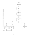
Fig. 4 shows a flow chart illustrating a method according to the invention. -
Fig. 1 shows in a front view aforage harvester 1 with aheader 3,ground wheels 5, a driver's cabin 7 and a discharge or ejectingspout 9. During work theheader 3 will harvest a crop, which is processed by theharvester 1 and ejected from thespout 9. To collect the ejected crop atransport wagon 11 is driven alongside theforage harvester 1. Of thetransport wagon 11 onlyground wheels 13 and a crop-carrying container with abottom 15,sidewalls open top 19, is shown inFig. 1 . - The
spout 9 is in a manner known per se mounted on theharvester 1 to be rotatable in a controlled manner around avertical axis 21 by means of actuators indicated bynumeral 22. A gauge is attached to theactuator 22, whereby the position of thespout 9 relative to theharvester 1 is known. Thespout 9 is elongated and has anouter end 23 provided with an adjustable hood 25 for directing acrop stream 27 ejected from thespout 9. - A 3D imaging device in the form of a
stereo camera 29 is mounted on thespout 9 on the lower side thereof and at a distance from theouter end 23. Thestereo camera 29 comprises two cameras, e.g. CCD cameras or video cameras, withobjective lenses 36a and 36b, respectively, having a mean view direction 39 of thestereo camera 29. The two cameras are accommodated in a common housing 41. - The stereo camera is preferably a wide-angle camera with a large viewing angle β allowing the camera to "see" simultaneously the open top 19 and the
nearest sidewall 17 of the crop-carrying container of thetransport wagon 11 as indicated inFig. 1 . - In the embodiment shown, apart from the joint providing for the rotation of the
spout 9 around thevertical axis 21, thespout 9 does not comprise any joints between the body of theharvester 1 and thecamera 29. Thus the position of thestereo camera 29, especially its height above the ground, is always known. It is envisaged that the spout in alternative embodiments comprises joints allowing the spout to be raised and lowered changing the overall geometry of the spout. In such embodiments gauges might be attached to the joints to allow establishment of the current geometry of the spout and thus of the height of the stereo camera's position above the ground. - The provision of the
stereo camera 29 provides for obtaining monochrome (or even colour) images as well as disparity images of the crop-carrying container. The monochrome images may e.g. be transferred to a monitor 44 in the driver's cabin to enable or help the driver monitoring the process of transferring crop to thetransport wagon 11 as it is known per se, while the disparity image is suited as an input for automatic or semi-automatic control. - Thus the
forage harvester 1 comprises acontrol device 46 with a data processor and a memory. The control device receives images or frames, i.e. data files comprising pixel information of the images, from thestereo camera 29 and process the images. - In the present embodiment the
control device 46 uses prior art software to process the stereo images received from thestereo camera 29. Thus thecontrol device 46 receives a stereo frame comprising a "left" and a "right" frame provided respectively by the twoobjective lenses 36a and 36b. It should be noted that "left" and "right" are used in relation to the two frames or pictures provided by the two objective lenses, as it is normal in relation to stereo vision, even though in the present embodiment the lenses are positioned one above the other rather than side by side. Thecontrol device 46 processes the stereo frame to provide a disparity picture, i.e. a picture comprising depth information i.e. 3D information. Normally the disparity picture is obtained analysing e.g. the left frame pixel by pixel, search for each pixel the corresponding pixel in the right frame and calculate the distance from the camera to the point imaged by those pixels by triangulation. Information of this distance is attached to the pixel of the left frame, which thus comprises the 3D information and constitutes the disparity picture. The disparity picture is processed by thecontrol device 46 using prior art software to recognise and locate thetransport wagon 11, especially the mainlyhorizontal rim 51 of the open top 19. - This requires a fairly good stereo picture without too much noise. Such pictures are frequently obtainable during operation, but also frequently they are not obtainable e.g. due to debris and dust flowing in the air around and below the
spout 9. - If the
control device 46 cannot with a sufficient degree of reliability recognise and locate the transport wagon on basis of a given frame it fails to establish the pose of the rim. - Having obtained a stereo frame or picture without too much noise and having therefrom established the pose of the
rim 51 of the open top it is possible to maintain or adjust the position of thespout 9 to aim the crop stream ejected by the spout at the target i.e. the open top 19 to fill the container of thetransport wagon 11. - The
transport wagon 11 comprises, as mentioned, two sidewalls i.e. aproximal sidewall 17 and adistal sidewall 18 relative to theharvester 1. Further thetransport wagon 11, or its crop carrying container, comprises a front wall 20a and a rear wall 20b. Correspondingly therim 51 comprises aproximal rim part 51a, a distal rim part 51b, a front rim part 51c and arear rim part 51d. - Having established the pose of the
rim 51 in a stereo picture the area of the picture between theproximal rim part 51a and the distal rim part 51b may be analysed pixel by pixel, and pixels which from the information of the disparity picture are adjudged to represent points situated mainly vertically below the distal rim part 51b are assigned to thedistal sidewall 18. - The information of the stereo frame, i.e. the disparity picture, is stored in the memory of the
control device 46 together with information about the pose of therim 51. The pose of the rim is referenced to theharvester 1. Thus the pose, i.e. position and attitude, of therim 51 and therewith thetransport wagon 11 relative to theharvester 1 is established. - Due to the fact that the position or height of the
stereo camera 29 above the ground is known, it is possible to filter out information relating to the ground, e.g. by eliminating any information relating to positions below 50 cm above the ground level. Elimination of information in this way reduces noise and data processing. - Having obtained and stored in this way information of a frame from which it has been possible to establish the pose of the
rim 51 or at least a part of the rim comprising either the front rim part 51c or therear rim part 51d together with adjacent parts of theproximal rim part 51a and the distal rim part 51b, this frame is denoted "reference frame". - Referring to
Fig. 4 the system proceeds as follows having obtained a reference frame in aninitial step 100. In afirst step 101 characteristic points are identified in the reference frame. In a second step 103 a new stereo frame is obtained from thestereo camera 29 and the new stereo frame is analysed to seek and identify characteristic points or distinctive features in the new stereo frame. - In a
third step 105 characteristic points found in the reference frame and the new stereo frame, respectively are matched to establish a group of characteristic points showing a common change of pose from the reference frame to the new stereo frame. The common change of pose thus found corresponds to the change of pose of thetransport wagon 11 relative to thestereo camera 29 during the time span between obtaining the reference frame and the new stereo frame. - If the quality of the new stereo frame is not sufficient to establish the pose of the
rim 51 or part thereof as explained above then in afourth step 107 the pose of therim 51 registered together with the information of the reference frame is updated by the common change of pose as a new pose, and thecontrol device 46 may provide any control signal appropriate to keep the crop stream ejected by thespout 9 aimed at the target, i.e. the open top 19 or a determined place within the open top 19. - If the quality of the new stereo frame is sufficient to determine the pose of the
rim 51 or part thereof, the new stereo frame is in an alternativefourth step 109 used as a new reference frame. -
Fig. 2 shows a picture of atransport wagon 11 wherein characteristic points found in said picture and a subsequent new picture are indicated aslines 53 extending between pairs of matched characteristic points. It is seen that no points are found on the surrounding ground, which has been filtered out as mentioned above. Thecrop stream 27 entering the container of thetransport wagon 11 is seen and it is noticed that no matched characteristic points are found in thecrop stream 27 or at its place of impact inside thetransport wagon 11. This is due to the fact that around thecrop stream 27 dusty conditions are present creating noise and the surface of the crop deposited in thetransport wagon 11 is kind of vivid or mobile in the area of impact of the crop stream due to the continuous arrival of crop. These conditions make it impossible to determine the actual position of the surface of the crop deposited in thetransport wagon 11 based on a single 3D image because for a given point or pixel found in the 3D image it is not possible to determine whether the point actually belongs to the surface of deposited crop or whether it belongs to the flowingcrop stream 27. However next to the place of impact of the crop stream the surface will locally be at rest during the time span between obtaining two subsequent frames and thus it is possible to identify and match characteristic points of the surface of the deposited goods. These points reliably indicate the current surface of the deposited crop, thus providing for determining the degree of filling of the container of thetransport wagon 11. - As mentioned above pixels positioned between the distal and the
proximal rim parts 51b and 51a are analysed to be possibly assigned to thedistal side wall 18. Identified and matched characteristic points positioned between the distal and theproximal rim parts 51b and 51a are assigned to the surface of deposited crop if they are not assigned to thedistal side wall 19. - In a fifth step 111 (
Fig. 4 ) a signal is sent to the monitor 44 as information for the driver or operator of theharvester 1. ThusFig. 3 shows a monitor picture of atransport wagon 11 in which therim 51 has been indicated by means of signals provided by the software recognising and locating the rim. The indication of the rim has the form of a picture frame 51' generated by thecontrol device 46 and superposed the picture provided from the camera i.e. one of the twoobjectives 36a and 36b. Further the degree of filling is indicated gradually for various longitudinal sections of thetransport wagon 11 bypicture fields control device 46 and superposed the picture provided from the camera. This indication of the degree of filling tells which parts of the container of the transport wagon has been sufficiently filled and which parts still have room for more crop. - Preferably colours are used to indicate various degrees of filling of different areas, e.g. indicating by a red colour that an area has been filled (field 61), indicating by a green colour areas that are far from filled (field 67), and indicating by one or more yellow nuances areas, which are close to being filled (field 63a, 63b and 65).
- Subsequently to the fourth and fifth steps the method returns to the
first step 101 using the information of the up-dated reference frame. - Identifying characteristic points in the
first step 101 and thesecond step 103 may be performed by any known method e.g. by any known method of so-called "Blob detection" or any known method of so-called "Corner detection". These methods provide a response for a pixel or small group of pixels centred around a pixel. A pixel having a response, but for which another pixel having a more pronounced response is found in its local neighbourhood, is rejected since weak responses are likely to cause noise. - Matching of characteristic points in the
third step 105 may be performed on basis of texture analysis of the vicinity of the respective points or features. Such analysis is made by means of a so-called "Feature descriptor", of which several are known in the art, e.g. Zero-mean Normal Cross Correlation, the SURF (Speeded Up Robust Features) descriptor and the SIFT (Scale-invariant feature transform) descriptor. - When matching a characteristic point found in the new stereo frame with a characteristic point in the reference frame, then the search for a possible match may be restricted to an area, where the correct match is expected to be found. Thus areas which are expected not to relate to the
transport wagon 11, but its surroundings e.g. on an external side the front rim part, may be excluded. - The
stereo camera 29's and thetransport wagon 11's mutual change of pose during the time between one frame (the reference frame) and another frame (the new stereo frame) is described by a transformation matrix M:
where
R is a 3 by 3 matrix (3 rows and 3 columns) expressing the rotation about three spatial axes, and
T is a 3 by 1 matrix defining the translation in three spatial directions;
M is thus a 4 by 4 matrix. - If Pa designates the reference frame of a time a and Pb designates the new stereo frame of a later time b, i.e. a<b, then
Pb = Mab*Pa, where Mab is a matrix expressing the transformation from a to b. - Cf. the
third step 105 mentioned above, M is in an embodiment of the present invention established by a RANSAC method: - If fas is characteristic point No. s in Pa, which have been matched with fbs, which is characteristic point No. s in Pb, and correspondingly fat is characteristic point No. t in Pa, which have been matched with fbt, which is characteristic point No. t in Pb, and fau is characteristic point No. u in Pa, which have been matched with fbu, which is characteristic point No. u in Pb, and if fs, ft and fu are non-collinear, then

constitutes an equation system from which Mab can be calculated. - Mab is according to a RANSAC method calculated as estimate a large number of times for randomly selected three matched pairs of characteristic points fa and fb. Once an estimate of Mab is thus calculated it is tested against the other matched pairs of characteristic points in Pa and Pb. Here through a best estimate of Mab is established. Matched pairs of characteristic points, which according to the best estimate of Mab appear to be mis-matches, are rejected as outliers.
- By the present invention several advantageous effect may be obtained:
- In periods when images obtained by the
stereo camera 29 are of a poor quality it is still possible to keep track off the mutual position of the stereo camera (and thus the harvester) and a target i.e. the transport wagon. - It is possible reliable to detect the current surface of a material in the target i.e. of crop in the transport wagon and thus the degree of filling (of the wagon).
- Further due to the fact that the pose of the rim or part thereof is established and information is stored, at least in a preferred embodiment, it is possible to keep track of either end of the container of the wagon i.e. the front rim part 51c and the
rear rim part 51d, once the respective rim part has been within the view of thecamera 29, even if theentire rim 51 is not within the view of the camera, i.e. is not represented in a given stereo frame, at any time.
Claims (15)
- A control system of an agricultural vehicle controlling a controllable goods carrier (9) of the agricultural vehicle (1), especially a discharge spout of a forage harvester, for conveying goods to a target area (11), said control system comprising a 3D imaging device (29) for providing frames imaging at least part of the target area, a data processor (46) and a memory (46), said control system deriving information from the frames for controlling the goods carrier (9), and said control system operating to
obtain a reference frame comprising 3D information about the pose of at least part of the target area (11),
identify a plurality of characteristic points of the target area (11) in the reference frame,
obtain from the 3D imaging device (29) a new frame imaging at least a part of the target area (11),
analyse the new frame to identify a plurality of characteristic points in the new frame,
search and match characteristic points in the reference frame and the new frame,
analyse pairs (53) of matched characteristic points to establish a group of pairs showing a common change of pose between the reference frame and the new frame, and
said control system operating to provide a signal taking into account results of the latter analysis. - A control system according to claim 1, wherein the control system operates to provide said signal taking into account said common change of pose and/or the relative positions of the individual pairs of matched characteristic points in the group of pairs showing a common change of pose.
- A control system according to claim 1 or 2, wherein said signal is a control signal for controlling the goods carrier.
- A control system according to any of the preceding claims, wherein the system comprises a monitor (44) and said signal is an information signal displayed (51', 61, 63a, 63b, 65, 67) on the monitor (44).
- A control system according to any of the preceding claims, wherein the control system operates to establish a pose of the target area corresponding to the reference frame and to update said pose taking into account said common change of pose.
- A control system according to any of the preceding claims, wherein the control system operates to establish the pose of at least part of the target area (11) in a reference system, preferably a reference system of the agricultural vehicle (1).
- A control system according to claims 5 and 6, wherein the control system operates to update the pose of the target area in said reference system.
- A control system according to any of the preceding claims, wherein the control system operates to establish surfaces (17, 18, 20a, 20b) of the target area (11) and to establish individual pairs (53) of matched characteristic points in the group of pairs showing a common change of pose, that are not positioned on a surface (17, 18, 20a, 20b) of the target area, as indicating a surface of the goods conveyed to the target area.
- A control system according to any of the preceding claims, wherein the control system comprises means for establishing the pose of at least part of the target area, said means providing a measure of degree of reliability of the established pose, said control system operating to update the pose of the target area using the pose established by the means for establishing the pose, when said degree of reliability is high.
- A control system according to claim 9, wherein said means for establishing the pose of at least part of the target area comprises means (46) for analysing a 3D frame.
- A control system according to any of the preceding claims, wherein the control system comprises means for establishing the position and direction of view of the 3D imaging device, and the control system operates to disregard points in the 3D frames indicating positions below a specific level below the 3D imaging device.
- A control system according to any of the preceding claims, wherein the control system operates to establish areas of expectation within which the searching of characteristic points in the reference frame and/or the new frame for matching is performed.
- A control system according to any of the preceding claims, wherein the control system operates to search and match characteristic points in the new frame with characteristic points in several previously obtained frames.
- An agricultural vehicle (1) comprising a control system controlling a controllable goods carrier (9) of the agricultural vehicle, especially a discharge spout of a forage harvester, for conveying goods to a target area (11), said control system comprising a 3D imaging device (29) for providing frames imaging at least part of the target area, a data processor (46) and a memory (46), said control system deriving information from the frames for controlling the goods carrier, and said control system operating to
obtain a reference frame comprising 3D information about the pose of at least part of the target area (11),
identify a plurality of characteristic points of the target area in the reference frame,
obtain from the 3D imaging device (29) a new frame imaging at least a part of the target area,
analyse the new frame to identify a plurality of characteristic points in the new frame,
search and match characteristic points in the reference frame and the new frame,
analyse pairs (53) of matched characteristic points to establish a group of pairs showing a common change of pose between the reference frame and the new frame, and
said control system operating to provide a signal taking into account results of the latter analysis. - A method of controlling by means of a control system a controllable goods carrier (9) of the agricultural vehicle (1), especially a discharge spout of a forage harvester, for conveying goods to a target area (11), said control system comprising a 3D imaging device (29) for providing frames imaging at least part of the target area, a data processor (46) and a memory (46), said control system deriving information from the frames for controlling the goods carrier, and said method comprising:obtaining a reference frame comprising 3D information about the pose of at least part of the target area (11),identifying a plurality of characteristic points of the target area in the reference frame,obtaining from the 3D imaging device (29) a new frame imaging at least a part of the target area,analysing the new frame to identify a plurality of characteristic points in the new frame,searching and matching characteristic points in the reference frame and the new frame,analysing pairs (53) of matched characteristic points to establish a group of pairs showing a common change of pose between the reference frame and the new frame, andproviding a signal taking into account results of the latter analysis.
Priority Applications (9)
| Application Number | Priority Date | Filing Date | Title |
|---|---|---|---|
| AT09169622T ATE533350T1 (en) | 2009-09-07 | 2009-09-07 | CONTROL SYSTEM OF AN AGRICULTURAL VEHICLE WITH A GOODS CARRIER, AGRICULTURAL VEHICLE AND METHOD FOR CONTROLLING A GOODS CARRIER OF THE AGRICULTURAL VEHICLE |
| EP20090169622 EP2301318B1 (en) | 2009-09-07 | 2009-09-07 | A control system of an agricultural vehicle with a goods carrier, an agricultural vehicle and a method of controlling a goods carrier of the agricultural vehicle |
| AT09170842T ATE536092T1 (en) | 2009-09-07 | 2009-09-21 | FILLING STRENGTH MEASUREMENT DEVICE, AGRICULTURAL VEHICLE HAVING SUCH A MEASUREMENT DEVICE AND METHOD FOR CONTROLLING THE FILLING OF A TARGET AREA |
| PL09170842T PL2311307T3 (en) | 2009-09-07 | 2009-09-21 | A filling degree gauge, an agricultural vehicle comprising such gauge, and a method of controlling filling of a target area |
| EP09170842A EP2311307B1 (en) | 2009-09-07 | 2009-09-21 | A filling degree gauge, an agricultural vehicle comprising such gauge, and a method of controlling filling of a target area |
| US12/868,885 US9107344B2 (en) | 2009-09-07 | 2010-08-26 | Control system of agricultural vehicle with goods carrier, agricultural vehicle, and method of controlling goods carrier of agricultural vehicle |
| US12/868,856 US8656693B2 (en) | 2009-09-07 | 2010-08-26 | Filling degree gauge, agricultural vehicle with the gauge, and method of measuring and displaying residual filling potential of target area |
| RU2010135813/13A RU2520148C2 (en) | 2009-09-07 | 2010-08-30 | Control system for agricultural vehicle, agricultural vehicle and method of control of controlled means of product transportation |
| RU2010136365/13A RU2529905C2 (en) | 2009-09-07 | 2010-09-02 | Measuring device of filling degree, agricultural vehicle and method of control of filling target area |
Applications Claiming Priority (1)
| Application Number | Priority Date | Filing Date | Title |
|---|---|---|---|
| EP20090169622 EP2301318B1 (en) | 2009-09-07 | 2009-09-07 | A control system of an agricultural vehicle with a goods carrier, an agricultural vehicle and a method of controlling a goods carrier of the agricultural vehicle |
Publications (2)
| Publication Number | Publication Date |
|---|---|
| EP2301318A1 EP2301318A1 (en) | 2011-03-30 |
| EP2301318B1 true EP2301318B1 (en) | 2011-11-16 |
Family
ID=41508268
Family Applications (1)
| Application Number | Title | Priority Date | Filing Date |
|---|---|---|---|
| EP20090169622 Active EP2301318B1 (en) | 2009-09-07 | 2009-09-07 | A control system of an agricultural vehicle with a goods carrier, an agricultural vehicle and a method of controlling a goods carrier of the agricultural vehicle |
Country Status (4)
| Country | Link |
|---|---|
| US (1) | US9107344B2 (en) |
| EP (1) | EP2301318B1 (en) |
| AT (2) | ATE533350T1 (en) |
| RU (1) | RU2529905C2 (en) |
Cited By (17)
| Publication number | Priority date | Publication date | Assignee | Title |
|---|---|---|---|---|
| US8626406B2 (en) | 2011-12-22 | 2014-01-07 | Deere & Company | Method and system for transferring material between vehicles |
| US8649940B2 (en) | 2012-02-10 | 2014-02-11 | Deere & Company | Method and stereo vision system for managing the unloading of an agricultural material from a vehicle |
| US8868304B2 (en) | 2012-02-10 | 2014-10-21 | Deere & Company | Method and stereo vision system for facilitating the unloading of agricultural material from a vehicle |
| US9126776B2 (en) | 2008-02-08 | 2015-09-08 | Wirtgen Gmbh | Milling machine, in particular surface miner, and method for mining milled material of an open cast surface |
| US9234319B2 (en) | 2012-08-23 | 2016-01-12 | Wirtgen Gmbh | Automotive milling machine, as well as method for steering an automotive milling machine |
| US9415953B2 (en) | 2012-02-10 | 2016-08-16 | Deere & Company, A Delaware Corporation | System and method of material handling using one imaging device on the receiving vehicle to control the material distribution into the storage portion of the receiving vehicle |
| US9642305B2 (en) | 2015-08-10 | 2017-05-09 | Deere & Company | Method and stereo vision system for managing the unloading of an agricultural material from a vehicle |
| US9764910B2 (en) | 2014-08-22 | 2017-09-19 | Wirtgen Gmbh | Automotive milling machine, as well as method for discharging milled material |
| US9809937B2 (en) | 2014-08-22 | 2017-11-07 | Wirtgen Gmbh | Automotive milling machine, as well as method for discharging milled material |
| US9861040B2 (en) | 2012-02-10 | 2018-01-09 | Deere & Company | Method and stereo vision system for facilitating the unloading of agricultural material from a vehicle |
| US9915043B2 (en) | 2012-08-23 | 2018-03-13 | Wirtgen Gmbh | Automotive milling machine, as well as method for unloading milled material |
| US10015928B2 (en) | 2015-08-10 | 2018-07-10 | Deere & Company | Method and stereo vision system for managing the unloading of an agricultural material from a vehicle |
| US10100470B2 (en) | 2014-08-21 | 2018-10-16 | Wirtgen Gmbh | Automotive milling machine, as well as method for discharging milled material |
| US10100471B2 (en) | 2007-04-19 | 2018-10-16 | Wirtgen Gmbh | Automotive construction machine |
| US10753052B2 (en) | 2016-11-16 | 2020-08-25 | Wirtgen Gmbh | Self-propelled milling machine, as well as method for controlling a self-propelled milling machine |
| EP3915353A1 (en) | 2020-05-29 | 2021-12-01 | CLAAS E-Systems GmbH | Method for determining the position of a camera mounted on a loading device of a self-propelled harvester |
| DE102020007112A1 (en) | 2020-11-20 | 2022-05-25 | Bomag Gmbh | METHOD OF CONTROLLING THE OPERATION OF A BULK MATERIAL LOADING CONVEYOR ATTACHED TO A SELF-PROPELLED ROAD OR OPEN MINE MACHINE RELATIVE TO A DUMP BODY OF A TRANSPORT VEHICLE AND ROAD OR OPEN MINE MACHINE FOR CARRYING OUT THE METHOD |
Families Citing this family (15)
| Publication number | Priority date | Publication date | Assignee | Title |
|---|---|---|---|---|
| US9392746B2 (en) | 2012-02-10 | 2016-07-19 | Deere & Company | Artificial intelligence for detecting and filling void areas of agricultural commodity containers |
| EP2792229B1 (en) * | 2013-04-02 | 2016-03-23 | Deere & Company | Control arrangement and method for controlling a position of a transfer device of a harvesting machine |
| GB2517049B (en) * | 2013-07-28 | 2019-09-11 | Deere & Co | Artificial intelligence for detecting and filling void areas of agricultural commodity containers |
| BE1021164B1 (en) | 2013-10-28 | 2016-01-18 | Cnh Industrial Belgium Nv | DISCHARGE SYSTEMS |
| RU2568695C1 (en) * | 2014-11-12 | 2015-11-20 | Общество с ограниченной ответственностью "Научно-производственное предприятие "Резонанс" | Working machine indicator |
| EP3150052B1 (en) | 2015-09-30 | 2018-06-13 | CLAAS E-Systems KGaA mbH & Co KG | Crop harvesting machine |
| PL3165078T3 (en) * | 2015-11-06 | 2020-11-02 | Exel Industries | Crop transfer device and corresponding method |
| US11266054B2 (en) | 2017-01-24 | 2022-03-08 | Cnh Industrial America Llc | System and method for automatically estimating and adjusting crop residue parameters as a tillage operation is being performed |
| DE102017220869A1 (en) | 2017-11-22 | 2019-05-23 | Wirtgen Gmbh | Self-propelled milling machine, method for automatically loading a means of transport with milled material, as well as road or soil treatment unit |
| CN108550141A (en) * | 2018-03-29 | 2018-09-18 | 上海大学 | A kind of movement wagon box automatic identification and localization method based on deep vision information |
| KR20210008045A (en) * | 2018-05-09 | 2021-01-20 | 트리나미엑스 게엠베하 | Method and device for determining the charge level of at least one storage unit |
| DE102019104218A1 (en) | 2019-02-19 | 2020-08-20 | Wirtgen Gmbh | Work train, comprising a tillage machine and another vehicle as well as an automated distance monitoring |
| CN111815679B (en) * | 2020-07-27 | 2022-07-26 | 西北工业大学 | Binocular camera-based trajectory prediction method during loss of spatial target feature points |
| US11980134B2 (en) | 2021-03-09 | 2024-05-14 | Deere & Company | Operator commanded placement for control of filling mechanisms |
| US11930738B2 (en) * | 2021-06-28 | 2024-03-19 | Deere & Company | Closed loop control of filling mechanisms |
Family Cites Families (16)
| Publication number | Priority date | Publication date | Assignee | Title |
|---|---|---|---|---|
| JPS5664605A (en) * | 1979-11-01 | 1981-06-01 | Mitsubishi Heavy Ind Ltd | Method for sensing distribution of height of stored material |
| DE4426059C2 (en) | 1994-07-25 | 2001-07-05 | Case Harvesting Sys Gmbh | harvester |
| DE19848127A1 (en) * | 1998-10-19 | 2000-04-20 | Claas Selbstfahr Erntemasch | Device for controlling a transfer device |
| DE10064860A1 (en) * | 2000-12-23 | 2002-06-27 | Claas Selbstfahr Erntemasch | Harvested crop transfer optimisation device uses control unit providing signals for controlling velocity and steering angle of crop transport vehicle adjacent harvesting machine |
| US6819780B2 (en) * | 2001-02-02 | 2004-11-16 | Cnh America Llc | Method and apparatus for automatically steering a vehicle in an agricultural field using a plurality of fuzzy logic membership functions |
| US6943824B2 (en) * | 2002-03-13 | 2005-09-13 | Deere & Company | Image processing spout control system |
| DE10240219A1 (en) * | 2002-08-28 | 2004-03-11 | Claas Selbstfahrende Erntemaschinen Gmbh | Device for controlling a transfer device |
| DE10244148A1 (en) * | 2002-09-23 | 2004-04-08 | Daimlerchrysler Ag | Method and device for video-based observation and measurement of the lateral surroundings of a vehicle |
| US7587081B2 (en) * | 2005-09-28 | 2009-09-08 | Deere & Company | Method for processing stereo vision data using image density |
| JP2009534415A (en) * | 2006-04-20 | 2009-09-24 | ザ リージェンツ オブ ザ ユニバーシティ オブ カリフォルニア | Pharmacological control of the action of AMPA receptor modulators on neurotrophin expression |
| US20070288147A1 (en) * | 2006-05-25 | 2007-12-13 | Reeves Barry H | System and method for indicating to a remote location operation of an auger or the like |
| US7822266B2 (en) * | 2006-06-02 | 2010-10-26 | Carnegie Mellon University | System and method for generating a terrain model for autonomous navigation in vegetation |
| JP2008182945A (en) * | 2007-01-30 | 2008-08-14 | Iseki & Co Ltd | Grain-unloading system |
| DE102007009666A1 (en) * | 2007-02-22 | 2008-08-28 | Carl Zeiss Microimaging Gmbh | Arrangement for filling a container with bulk material |
| EP2020174B1 (en) | 2007-08-03 | 2012-02-29 | AGROCOM GmbH & Co. Agrarsystem KG | Agricultural working machine |
| US20090276108A1 (en) * | 2008-05-01 | 2009-11-05 | Ajith Kuttannair Kumar | System and method for processing images of wayside equipment adjacent to a route |
-
2009
- 2009-09-07 EP EP20090169622 patent/EP2301318B1/en active Active
- 2009-09-07 AT AT09169622T patent/ATE533350T1/en active
- 2009-09-21 AT AT09170842T patent/ATE536092T1/en active
-
2010
- 2010-08-26 US US12/868,885 patent/US9107344B2/en active Active
- 2010-09-02 RU RU2010136365/13A patent/RU2529905C2/en active
Cited By (32)
| Publication number | Priority date | Publication date | Assignee | Title |
|---|---|---|---|---|
| US10100471B2 (en) | 2007-04-19 | 2018-10-16 | Wirtgen Gmbh | Automotive construction machine |
| US10077655B2 (en) | 2008-02-08 | 2018-09-18 | Wirtgen Gmbh | Milling machine, in particular surface miner, and method for mining milled material of an open cast surface |
| US9126776B2 (en) | 2008-02-08 | 2015-09-08 | Wirtgen Gmbh | Milling machine, in particular surface miner, and method for mining milled material of an open cast surface |
| US8626406B2 (en) | 2011-12-22 | 2014-01-07 | Deere & Company | Method and system for transferring material between vehicles |
| US9457971B2 (en) | 2012-02-10 | 2016-10-04 | Deere & Company | System and method of material handling using one or more imaging devices on the transferring vehicle to control the material distribution into the storage portion of the receiving vehicle |
| US9415953B2 (en) | 2012-02-10 | 2016-08-16 | Deere & Company, A Delaware Corporation | System and method of material handling using one imaging device on the receiving vehicle to control the material distribution into the storage portion of the receiving vehicle |
| US11252869B2 (en) | 2012-02-10 | 2022-02-22 | Deere & Company | Imaging system for facilitating the unloading of agricultural material from a vehicle |
| US9463939B2 (en) | 2012-02-10 | 2016-10-11 | Deere & Company | System and method of material handling using one or more imaging devices on the transferring vehicle and on the receiving vehicle to control the material distribution into the storage portion of the receiving vehicle |
| US9511958B2 (en) | 2012-02-10 | 2016-12-06 | Deere & Company | System and method of material handling using one imaging device on the receiving vehicle to control the material distribution into the storage portion of the receiving vehicle |
| US9522792B2 (en) | 2012-02-10 | 2016-12-20 | Deere & Company | System and method of material handling using one or more imaging devices on the transferring vehicle and on the receiving vehicle to control the material distribution into the storage portion of the receiving vehicle |
| US9522791B2 (en) | 2012-02-10 | 2016-12-20 | Carnegie Mellon University, A Pennsylvania Non-Profit Corporation | System and method of material handling using one or more imaging devices on the transferring vehicle to control the material distribution into the storage portion of the receiving vehicle |
| US10631462B2 (en) | 2012-02-10 | 2020-04-28 | Deere & Company | Method and stereo vision system for facilitating unloading of agricultural material from a vehicle |
| US8868304B2 (en) | 2012-02-10 | 2014-10-21 | Deere & Company | Method and stereo vision system for facilitating the unloading of agricultural material from a vehicle |
| US8649940B2 (en) | 2012-02-10 | 2014-02-11 | Deere & Company | Method and stereo vision system for managing the unloading of an agricultural material from a vehicle |
| US9861040B2 (en) | 2012-02-10 | 2018-01-09 | Deere & Company | Method and stereo vision system for facilitating the unloading of agricultural material from a vehicle |
| US9915043B2 (en) | 2012-08-23 | 2018-03-13 | Wirtgen Gmbh | Automotive milling machine, as well as method for unloading milled material |
| US9234319B2 (en) | 2012-08-23 | 2016-01-12 | Wirtgen Gmbh | Automotive milling machine, as well as method for steering an automotive milling machine |
| US9873993B2 (en) | 2012-08-23 | 2018-01-23 | Wirtgen Gmbh | Automotive milling machine, as well as method for steering an automotive milling machine |
| US10100470B2 (en) | 2014-08-21 | 2018-10-16 | Wirtgen Gmbh | Automotive milling machine, as well as method for discharging milled material |
| US10697135B2 (en) | 2014-08-21 | 2020-06-30 | Wirtgen Gmbh | Automotive milling machine, as well as method for discharging milled material |
| US9809937B2 (en) | 2014-08-22 | 2017-11-07 | Wirtgen Gmbh | Automotive milling machine, as well as method for discharging milled material |
| US9764910B2 (en) | 2014-08-22 | 2017-09-19 | Wirtgen Gmbh | Automotive milling machine, as well as method for discharging milled material |
| US10196784B2 (en) | 2014-08-22 | 2019-02-05 | Wirtgen Gmbh | Automotive milling machine, as well as method for discharging milled material |
| US10015928B2 (en) | 2015-08-10 | 2018-07-10 | Deere & Company | Method and stereo vision system for managing the unloading of an agricultural material from a vehicle |
| US9642305B2 (en) | 2015-08-10 | 2017-05-09 | Deere & Company | Method and stereo vision system for managing the unloading of an agricultural material from a vehicle |
| US10753052B2 (en) | 2016-11-16 | 2020-08-25 | Wirtgen Gmbh | Self-propelled milling machine, as well as method for controlling a self-propelled milling machine |
| US11466412B2 (en) | 2016-11-16 | 2022-10-11 | Wirtgen Gmbh | Self-propelled milling machine, as well as method for controlling a self-propelled milling machine |
| US11761155B2 (en) | 2016-11-16 | 2023-09-19 | Wirtgen Gmbh | Self-propelled milling machine, as well as method for controlling a self-propelled milling machine |
| DE102020114498A1 (en) | 2020-05-29 | 2021-12-02 | Claas E-Systems Gmbh | Method for determining the position of a camera arranged on a transfer device of a self-propelled harvesting machine |
| EP3915353A1 (en) | 2020-05-29 | 2021-12-01 | CLAAS E-Systems GmbH | Method for determining the position of a camera mounted on a loading device of a self-propelled harvester |
| DE102020007112A1 (en) | 2020-11-20 | 2022-05-25 | Bomag Gmbh | METHOD OF CONTROLLING THE OPERATION OF A BULK MATERIAL LOADING CONVEYOR ATTACHED TO A SELF-PROPELLED ROAD OR OPEN MINE MACHINE RELATIVE TO A DUMP BODY OF A TRANSPORT VEHICLE AND ROAD OR OPEN MINE MACHINE FOR CARRYING OUT THE METHOD |
| EP4001507A1 (en) | 2020-11-20 | 2022-05-25 | BOMAG GmbH | Method for controlling the operation of a loading conveyor belt for bulk material arranged on a self-propelled road construction or surface mining machine relative to a transport trough of a transport vehicle, as well as a road construction or surface mining machine for carrying out the method |
Also Published As
| Publication number | Publication date |
|---|---|
| ATE533350T1 (en) | 2011-12-15 |
| US9107344B2 (en) | 2015-08-18 |
| RU2529905C2 (en) | 2014-10-10 |
| EP2301318A1 (en) | 2011-03-30 |
| ATE536092T1 (en) | 2011-12-15 |
| RU2010136365A (en) | 2012-03-10 |
| US20110064274A1 (en) | 2011-03-17 |
Similar Documents
| Publication | Publication Date | Title |
|---|---|---|
| EP2301318B1 (en) | A control system of an agricultural vehicle with a goods carrier, an agricultural vehicle and a method of controlling a goods carrier of the agricultural vehicle | |
| EP2311307B1 (en) | A filling degree gauge, an agricultural vehicle comprising such gauge, and a method of controlling filling of a target area | |
| EP3192345B1 (en) | Fill level indicator for an automated unloading system | |
| EP3406123B1 (en) | Aerial vehicle systems and methods | |
| EP3315005B1 (en) | Stereo vision system for managing the unloading of an agricultural material from a vehicle | |
| EP2812791B1 (en) | Method and stereo vision system for facilitating the unloading of agricultural material from a vehicle | |
| CN104220351B (en) | For being easy to unload method and the stereo visual system of agricultural material from vehicle | |
| US20200068804A1 (en) | Agricultural work machine | |
| DE102016214320A1 (en) | A method and stereo vision system for managing the unloading of an agricultural material from a vehicle | |
| EP3316218A1 (en) | Control arrangement and method for controlling a position of a transfer device of a harvesting machine | |
| US20230113645A1 (en) | Harverster systems and methods for automated and semi-automated filling of bins of receiving vehicles | |
| CN113766824B (en) | Harvester, obstacle determination program, recording medium, and obstacle determination method | |
| EP4095642B1 (en) | Material detection and handling of material irregularities | |
| WO2020218528A1 (en) | Agricultural machine such as harvester | |
| EP4356716A1 (en) | System and method for assisted or automated crop transfer | |
| US20230114174A1 (en) | Harverster systems and methods for automated and semi-automated filling of groups of receiving vehicles | |
| US20240130292A1 (en) | System And Method For Assisted Or Automated Crop Transfer | |
| US20240130293A1 (en) | System And Method For Assisted Or Automated Crop Transfer | |
| US20240130291A1 (en) | System And Method For Assisted Or Automated Crop Transfer | |
| WO2024110795A1 (en) | Agricultural machine monitoring | |
| AU2022200213A1 (en) | Harvester with feed forward control of filling mechanisms | |
| CN118104468A (en) | Harvesting system | |
| WO2022130038A1 (en) | System and method of assisted or automated grain unload synchronization | |
| JP2022081049A (en) | Transplanter |
Legal Events
| Date | Code | Title | Description |
|---|---|---|---|
| PUAI | Public reference made under article 153(3) epc to a published international application that has entered the european phase |
Free format text: ORIGINAL CODE: 0009012 |
|
| 17P | Request for examination filed |
Effective date: 20100721 |
|
| AK | Designated contracting states |
Kind code of ref document: A1 Designated state(s): AT BE BG CH CY CZ DE DK EE ES FI FR GB GR HR HU IE IS IT LI LT LU LV MC MK MT NL NO PL PT RO SE SI SK SM TR |
|
| AX | Request for extension of the european patent |
Extension state: AL BA RS |
|
| GRAP | Despatch of communication of intention to grant a patent |
Free format text: ORIGINAL CODE: EPIDOSNIGR1 |
|
| GRAS | Grant fee paid |
Free format text: ORIGINAL CODE: EPIDOSNIGR3 |
|
| GRAA | (expected) grant |
Free format text: ORIGINAL CODE: 0009210 |
|
| AK | Designated contracting states |
Kind code of ref document: B1 Designated state(s): AT BE BG CH CY CZ DE DK EE ES FI FR GB GR HR HU IE IS IT LI LT LU LV MC MK MT NL NO PL PT RO SE SI SK SM TR |
|
| AX | Request for extension of the european patent |
Extension state: AL BA RS |
|
| REG | Reference to a national code |
Ref country code: GB Ref legal event code: FG4D |
|
| REG | Reference to a national code |
Ref country code: CH Ref legal event code: EP |
|
| REG | Reference to a national code |
Ref country code: IE Ref legal event code: FG4D |
|
| REG | Reference to a national code |
Ref country code: DE Ref legal event code: R096 Ref document number: 602009003704 Country of ref document: DE Effective date: 20120112 |
|
| REG | Reference to a national code |
Ref country code: NL Ref legal event code: VDEP Effective date: 20111116 |
|
| LTIE | Lt: invalidation of european patent or patent extension |
Effective date: 20111116 |
|
| PG25 | Lapsed in a contracting state [announced via postgrant information from national office to epo] |
Ref country code: LT Free format text: LAPSE BECAUSE OF FAILURE TO SUBMIT A TRANSLATION OF THE DESCRIPTION OR TO PAY THE FEE WITHIN THE PRESCRIBED TIME-LIMIT Effective date: 20111116 Ref country code: NO Free format text: LAPSE BECAUSE OF FAILURE TO SUBMIT A TRANSLATION OF THE DESCRIPTION OR TO PAY THE FEE WITHIN THE PRESCRIBED TIME-LIMIT Effective date: 20120216 Ref country code: IS Free format text: LAPSE BECAUSE OF FAILURE TO SUBMIT A TRANSLATION OF THE DESCRIPTION OR TO PAY THE FEE WITHIN THE PRESCRIBED TIME-LIMIT Effective date: 20120316 |
|
| PG25 | Lapsed in a contracting state [announced via postgrant information from national office to epo] |
Ref country code: SE Free format text: LAPSE BECAUSE OF FAILURE TO SUBMIT A TRANSLATION OF THE DESCRIPTION OR TO PAY THE FEE WITHIN THE PRESCRIBED TIME-LIMIT Effective date: 20111116 Ref country code: HR Free format text: LAPSE BECAUSE OF FAILURE TO SUBMIT A TRANSLATION OF THE DESCRIPTION OR TO PAY THE FEE WITHIN THE PRESCRIBED TIME-LIMIT Effective date: 20111116 Ref country code: SI Free format text: LAPSE BECAUSE OF FAILURE TO SUBMIT A TRANSLATION OF THE DESCRIPTION OR TO PAY THE FEE WITHIN THE PRESCRIBED TIME-LIMIT Effective date: 20111116 Ref country code: PT Free format text: LAPSE BECAUSE OF FAILURE TO SUBMIT A TRANSLATION OF THE DESCRIPTION OR TO PAY THE FEE WITHIN THE PRESCRIBED TIME-LIMIT Effective date: 20120316 Ref country code: PL Free format text: LAPSE BECAUSE OF FAILURE TO SUBMIT A TRANSLATION OF THE DESCRIPTION OR TO PAY THE FEE WITHIN THE PRESCRIBED TIME-LIMIT Effective date: 20111116 Ref country code: GR Free format text: LAPSE BECAUSE OF FAILURE TO SUBMIT A TRANSLATION OF THE DESCRIPTION OR TO PAY THE FEE WITHIN THE PRESCRIBED TIME-LIMIT Effective date: 20120217 Ref country code: LV Free format text: LAPSE BECAUSE OF FAILURE TO SUBMIT A TRANSLATION OF THE DESCRIPTION OR TO PAY THE FEE WITHIN THE PRESCRIBED TIME-LIMIT Effective date: 20111116 Ref country code: NL Free format text: LAPSE BECAUSE OF FAILURE TO SUBMIT A TRANSLATION OF THE DESCRIPTION OR TO PAY THE FEE WITHIN THE PRESCRIBED TIME-LIMIT Effective date: 20111116 |
|
| PG25 | Lapsed in a contracting state [announced via postgrant information from national office to epo] |
Ref country code: CY Free format text: LAPSE BECAUSE OF FAILURE TO SUBMIT A TRANSLATION OF THE DESCRIPTION OR TO PAY THE FEE WITHIN THE PRESCRIBED TIME-LIMIT Effective date: 20111116 |
|
| PG25 | Lapsed in a contracting state [announced via postgrant information from national office to epo] |
Ref country code: SK Free format text: LAPSE BECAUSE OF FAILURE TO SUBMIT A TRANSLATION OF THE DESCRIPTION OR TO PAY THE FEE WITHIN THE PRESCRIBED TIME-LIMIT Effective date: 20111116 Ref country code: CZ Free format text: LAPSE BECAUSE OF FAILURE TO SUBMIT A TRANSLATION OF THE DESCRIPTION OR TO PAY THE FEE WITHIN THE PRESCRIBED TIME-LIMIT Effective date: 20111116 Ref country code: DK Free format text: LAPSE BECAUSE OF FAILURE TO SUBMIT A TRANSLATION OF THE DESCRIPTION OR TO PAY THE FEE WITHIN THE PRESCRIBED TIME-LIMIT Effective date: 20111116 Ref country code: EE Free format text: LAPSE BECAUSE OF FAILURE TO SUBMIT A TRANSLATION OF THE DESCRIPTION OR TO PAY THE FEE WITHIN THE PRESCRIBED TIME-LIMIT Effective date: 20111116 Ref country code: BG Free format text: LAPSE BECAUSE OF FAILURE TO SUBMIT A TRANSLATION OF THE DESCRIPTION OR TO PAY THE FEE WITHIN THE PRESCRIBED TIME-LIMIT Effective date: 20120216 |
|
| PLBI | Opposition filed |
Free format text: ORIGINAL CODE: 0009260 |
|
| PG25 | Lapsed in a contracting state [announced via postgrant information from national office to epo] |
Ref country code: RO Free format text: LAPSE BECAUSE OF FAILURE TO SUBMIT A TRANSLATION OF THE DESCRIPTION OR TO PAY THE FEE WITHIN THE PRESCRIBED TIME-LIMIT Effective date: 20111116 Ref country code: IT Free format text: LAPSE BECAUSE OF FAILURE TO SUBMIT A TRANSLATION OF THE DESCRIPTION OR TO PAY THE FEE WITHIN THE PRESCRIBED TIME-LIMIT Effective date: 20111116 |
|
| 26 | Opposition filed |
Opponent name: DEERE & COMPANY Effective date: 20120730 |
|
| REG | Reference to a national code |
Ref country code: AT Ref legal event code: MK05 Ref document number: 533350 Country of ref document: AT Kind code of ref document: T Effective date: 20111116 |
|
| PLAX | Notice of opposition and request to file observation + time limit sent |
Free format text: ORIGINAL CODE: EPIDOSNOBS2 |
|
| REG | Reference to a national code |
Ref country code: DE Ref legal event code: R026 Ref document number: 602009003704 Country of ref document: DE Effective date: 20120730 |
|
| PG25 | Lapsed in a contracting state [announced via postgrant information from national office to epo] |
Ref country code: AT Free format text: LAPSE BECAUSE OF FAILURE TO SUBMIT A TRANSLATION OF THE DESCRIPTION OR TO PAY THE FEE WITHIN THE PRESCRIBED TIME-LIMIT Effective date: 20111116 |
|
| PG25 | Lapsed in a contracting state [announced via postgrant information from national office to epo] |
Ref country code: ES Free format text: LAPSE BECAUSE OF FAILURE TO SUBMIT A TRANSLATION OF THE DESCRIPTION OR TO PAY THE FEE WITHIN THE PRESCRIBED TIME-LIMIT Effective date: 20120227 Ref country code: MC Free format text: LAPSE BECAUSE OF NON-PAYMENT OF DUE FEES Effective date: 20120930 |
|
| PLBB | Reply of patent proprietor to notice(s) of opposition received |
Free format text: ORIGINAL CODE: EPIDOSNOBS3 |
|
| REG | Reference to a national code |
Ref country code: IE Ref legal event code: MM4A |
|
| PG25 | Lapsed in a contracting state [announced via postgrant information from national office to epo] |
Ref country code: FI Free format text: LAPSE BECAUSE OF FAILURE TO SUBMIT A TRANSLATION OF THE DESCRIPTION OR TO PAY THE FEE WITHIN THE PRESCRIBED TIME-LIMIT Effective date: 20111116 |
|
| PG25 | Lapsed in a contracting state [announced via postgrant information from national office to epo] |
Ref country code: IE Free format text: LAPSE BECAUSE OF NON-PAYMENT OF DUE FEES Effective date: 20120907 |
|
| PG25 | Lapsed in a contracting state [announced via postgrant information from national office to epo] |
Ref country code: MT Free format text: LAPSE BECAUSE OF FAILURE TO SUBMIT A TRANSLATION OF THE DESCRIPTION OR TO PAY THE FEE WITHIN THE PRESCRIBED TIME-LIMIT Effective date: 20111116 |
|
| PG25 | Lapsed in a contracting state [announced via postgrant information from national office to epo] |
Ref country code: TR Free format text: LAPSE BECAUSE OF FAILURE TO SUBMIT A TRANSLATION OF THE DESCRIPTION OR TO PAY THE FEE WITHIN THE PRESCRIBED TIME-LIMIT Effective date: 20111116 |
|
| REG | Reference to a national code |
Ref country code: CH Ref legal event code: PL |
|
| PG25 | Lapsed in a contracting state [announced via postgrant information from national office to epo] |
Ref country code: LU Free format text: LAPSE BECAUSE OF NON-PAYMENT OF DUE FEES Effective date: 20120907 Ref country code: SM Free format text: LAPSE BECAUSE OF FAILURE TO SUBMIT A TRANSLATION OF THE DESCRIPTION OR TO PAY THE FEE WITHIN THE PRESCRIBED TIME-LIMIT Effective date: 20111116 |
|
| PG25 | Lapsed in a contracting state [announced via postgrant information from national office to epo] |
Ref country code: LI Free format text: LAPSE BECAUSE OF NON-PAYMENT OF DUE FEES Effective date: 20130930 Ref country code: CH Free format text: LAPSE BECAUSE OF NON-PAYMENT OF DUE FEES Effective date: 20130930 Ref country code: HU Free format text: LAPSE BECAUSE OF FAILURE TO SUBMIT A TRANSLATION OF THE DESCRIPTION OR TO PAY THE FEE WITHIN THE PRESCRIBED TIME-LIMIT Effective date: 20090907 |
|
| REG | Reference to a national code |
Ref country code: DE Ref legal event code: R100 Ref document number: 602009003704 Country of ref document: DE |
|
| PLCK | Communication despatched that opposition was rejected |
Free format text: ORIGINAL CODE: EPIDOSNREJ1 |
|
| PLBN | Opposition rejected |
Free format text: ORIGINAL CODE: 0009273 |
|
| STAA | Information on the status of an ep patent application or granted ep patent |
Free format text: STATUS: OPPOSITION REJECTED |
|
| 27O | Opposition rejected |
Effective date: 20140919 |
|
| REG | Reference to a national code |
Ref country code: DE Ref legal event code: R100 Ref document number: 602009003704 Country of ref document: DE Effective date: 20140919 |
|
| PG25 | Lapsed in a contracting state [announced via postgrant information from national office to epo] |
Ref country code: MK Free format text: LAPSE BECAUSE OF FAILURE TO SUBMIT A TRANSLATION OF THE DESCRIPTION OR TO PAY THE FEE WITHIN THE PRESCRIBED TIME-LIMIT Effective date: 20111116 |
|
| REG | Reference to a national code |
Ref country code: FR Ref legal event code: PLFP Year of fee payment: 7 |
|
| REG | Reference to a national code |
Ref country code: FR Ref legal event code: CD Owner name: CLAAS E-SYSTEMS KGAA MBH & CO KG, DE Effective date: 20160202 |
|
| REG | Reference to a national code |
Ref country code: DE Ref legal event code: R081 Ref document number: 602009003704 Country of ref document: DE Owner name: CLAAS E-SYSTEMS GMBH, DE Free format text: FORMER OWNER: CLAAS AGROSYSTEMS GMBH & CO. KG, 33330 GUETERSLOH, DE Ref country code: DE Ref legal event code: R081 Ref document number: 602009003704 Country of ref document: DE Owner name: CLAAS E-SYSTEMS KGAA MBH & CO. KG, DE Free format text: FORMER OWNER: CLAAS AGROSYSTEMS GMBH & CO. KG, 33330 GUETERSLOH, DE Ref country code: DE Ref legal event code: R081 Ref document number: 602009003704 Country of ref document: DE Owner name: CLAAS E-SYSTEMS KGAA MBH, DE Free format text: FORMER OWNER: CLAAS AGROSYSTEMS GMBH & CO. KG, 33330 GUETERSLOH, DE Ref country code: DE Ref legal event code: R081 Ref document number: 602009003704 Country of ref document: DE Owner name: CLAAS E-SYSTEMS KGAA MBH & CO KG, DE Free format text: FORMER OWNER: CLAAS AGROSYSTEMS GMBH & CO. KG, 33330 GUETERSLOH, DE |
|
| REG | Reference to a national code |
Ref country code: FR Ref legal event code: PLFP Year of fee payment: 8 |
|
| REG | Reference to a national code |
Ref country code: FR Ref legal event code: PLFP Year of fee payment: 9 |
|
| REG | Reference to a national code |
Ref country code: DE Ref legal event code: R081 Ref document number: 602009003704 Country of ref document: DE Owner name: CLAAS E-SYSTEMS GMBH, DE Free format text: FORMER OWNER: CLAAS E-SYSTEMS KGAA MBH & CO. KG, 33330 GUETERSLOH, DE Ref country code: DE Ref legal event code: R081 Ref document number: 602009003704 Country of ref document: DE Owner name: CLAAS E-SYSTEMS KGAA MBH, DE Free format text: FORMER OWNER: CLAAS E-SYSTEMS KGAA MBH & CO. KG, 33330 GUETERSLOH, DE Ref country code: DE Ref legal event code: R081 Ref document number: 602009003704 Country of ref document: DE Owner name: CLAAS E-SYSTEMS KGAA MBH & CO KG, DE Free format text: FORMER OWNER: CLAAS E-SYSTEMS KGAA MBH & CO. KG, 33330 GUETERSLOH, DE |
|
| REG | Reference to a national code |
Ref country code: DE Ref legal event code: R081 Ref document number: 602009003704 Country of ref document: DE Owner name: CLAAS E-SYSTEMS GMBH, DE Free format text: FORMER OWNER: CLAAS E-SYSTEMS KGAA MBH, 49201 DISSEN, DE Ref country code: DE Ref legal event code: R081 Ref document number: 602009003704 Country of ref document: DE Owner name: CLAAS E-SYSTEMS KGAA MBH & CO KG, DE Free format text: FORMER OWNER: CLAAS E-SYSTEMS KGAA MBH, 49201 DISSEN, DE |
|
| REG | Reference to a national code |
Ref country code: FR Ref legal event code: CA Effective date: 20180316 |
|
| REG | Reference to a national code |
Ref country code: FR Ref legal event code: PLFP Year of fee payment: 10 |
|
| REG | Reference to a national code |
Ref country code: DE Ref legal event code: R081 Ref document number: 602009003704 Country of ref document: DE Owner name: CLAAS E-SYSTEMS GMBH, DE Free format text: FORMER OWNER: CLAAS E-SYSTEMS KGAA MBH & CO KG, 49201 DISSEN, DE |
|
| REG | Reference to a national code |
Ref country code: BE Ref legal event code: HC Owner name: CLAAS E-SYSTEMS KGAA MBH & CO KG; DE Free format text: DETAILS ASSIGNMENT: CHANGE OF OWNER(S), CHANGEMENT NOM PROPRIETAIRE; FORMER OWNER NAME: CLAAS AGROSYSTEMS KGAA MBH & CO KG Effective date: 20150320 Ref country code: BE Ref legal event code: HC Owner name: CLAAS E-SYSTEMS GMBH; DE Free format text: DETAILS ASSIGNMENT: CHANGE OF OWNER(S), CHANGEMENT DE NOM DU PROPRIETAIRE; FORMER OWNER NAME: CLAAS E-SYSTEMS VERWALTUNGS GMBH Effective date: 20190403 Ref country code: BE Ref legal event code: PD Owner name: CLAAS AGROSYSTEMS KGAA MBH & CO KG; DE Free format text: DETAILS ASSIGNMENT: CHANGE OF OWNER(S), CHANGEMENT D'ENTITE JURIDIQUE; FORMER OWNER NAME: CLAAS AGROSYSTEMS GMBH & CO. KG Effective date: 20150320 Ref country code: BE Ref legal event code: PD Owner name: CLAAS E-SYSTEMS VERWALTUNGS GMBH; DE Free format text: DETAILS ASSIGNMENT: CHANGE OF OWNER(S), CESSION; FORMER OWNER NAME: CLAAS E-SYSTEMS KGAA MBH & CO KG Effective date: 20190403 |
|
| P01 | Opt-out of the competence of the unified patent court (upc) registered |
Effective date: 20230515 |
|
| PGFP | Annual fee paid to national office [announced via postgrant information from national office to epo] |
Ref country code: GB Payment date: 20230920 Year of fee payment: 15 |
|
| PGFP | Annual fee paid to national office [announced via postgrant information from national office to epo] |
Ref country code: FR Payment date: 20230928 Year of fee payment: 15 Ref country code: DE Payment date: 20230920 Year of fee payment: 15 Ref country code: BE Payment date: 20230920 Year of fee payment: 15 |