EP2300925B1 - System to connect a serial scsi array controller to a storage area network - Google Patents
System to connect a serial scsi array controller to a storage area network Download PDFInfo
- Publication number
- EP2300925B1 EP2300925B1 EP08795485.5A EP08795485A EP2300925B1 EP 2300925 B1 EP2300925 B1 EP 2300925B1 EP 08795485 A EP08795485 A EP 08795485A EP 2300925 B1 EP2300925 B1 EP 2300925B1
- Authority
- EP
- European Patent Office
- Prior art keywords
- circuit
- format
- sas
- data packets
- storage area
- Prior art date
- Legal status (The legal status is an assumption and is not a legal conclusion. Google has not performed a legal analysis and makes no representation as to the accuracy of the status listed.)
- Active
Links
- 239000000835 fiber Substances 0.000 claims description 19
- 239000003999 initiator Substances 0.000 claims description 18
- 238000000034 method Methods 0.000 claims description 7
- 238000004891 communication Methods 0.000 claims description 3
- 238000010586 diagram Methods 0.000 description 10
- 238000006243 chemical reaction Methods 0.000 description 7
- 230000006870 function Effects 0.000 description 2
- 238000012546 transfer Methods 0.000 description 2
- 238000012384 transportation and delivery Methods 0.000 description 2
- 238000013459 approach Methods 0.000 description 1
- 238000003491 array Methods 0.000 description 1
- 230000003139 buffering effect Effects 0.000 description 1
- 238000013461 design Methods 0.000 description 1
- 230000009977 dual effect Effects 0.000 description 1
- 238000005516 engineering process Methods 0.000 description 1
- 239000004744 fabric Substances 0.000 description 1
- 238000007726 management method Methods 0.000 description 1
- 238000013439 planning Methods 0.000 description 1
- 238000012545 processing Methods 0.000 description 1
- 230000004044 response Effects 0.000 description 1
Images


Classifications
-
- G—PHYSICS
- G06—COMPUTING; CALCULATING OR COUNTING
- G06F—ELECTRIC DIGITAL DATA PROCESSING
- G06F15/00—Digital computers in general; Data processing equipment in general
- G06F15/16—Combinations of two or more digital computers each having at least an arithmetic unit, a program unit and a register, e.g. for a simultaneous processing of several programs
-
- H—ELECTRICITY
- H04—ELECTRIC COMMUNICATION TECHNIQUE
- H04L—TRANSMISSION OF DIGITAL INFORMATION, e.g. TELEGRAPHIC COMMUNICATION
- H04L67/00—Network arrangements or protocols for supporting network services or applications
- H04L67/01—Protocols
- H04L67/10—Protocols in which an application is distributed across nodes in the network
- H04L67/1097—Protocols in which an application is distributed across nodes in the network for distributed storage of data in networks, e.g. transport arrangements for network file system [NFS], storage area networks [SAN] or network attached storage [NAS]
-
- G—PHYSICS
- G06—COMPUTING; CALCULATING OR COUNTING
- G06F—ELECTRIC DIGITAL DATA PROCESSING
- G06F13/00—Interconnection of, or transfer of information or other signals between, memories, input/output devices or central processing units
- G06F13/38—Information transfer, e.g. on bus
- G06F13/40—Bus structure
- G06F13/4004—Coupling between buses
- G06F13/4022—Coupling between buses using switching circuits, e.g. switching matrix, connection or expansion network
-
- G—PHYSICS
- G06—COMPUTING; CALCULATING OR COUNTING
- G06F—ELECTRIC DIGITAL DATA PROCESSING
- G06F3/00—Input arrangements for transferring data to be processed into a form capable of being handled by the computer; Output arrangements for transferring data from processing unit to output unit, e.g. interface arrangements
- G06F3/06—Digital input from, or digital output to, record carriers, e.g. RAID, emulated record carriers or networked record carriers
- G06F3/0601—Interfaces specially adapted for storage systems
- G06F3/0602—Interfaces specially adapted for storage systems specifically adapted to achieve a particular effect
- G06F3/0604—Improving or facilitating administration, e.g. storage management
- G06F3/0607—Improving or facilitating administration, e.g. storage management by facilitating the process of upgrading existing storage systems, e.g. for improving compatibility between host and storage device
-
- G—PHYSICS
- G06—COMPUTING; CALCULATING OR COUNTING
- G06F—ELECTRIC DIGITAL DATA PROCESSING
- G06F3/00—Input arrangements for transferring data to be processed into a form capable of being handled by the computer; Output arrangements for transferring data from processing unit to output unit, e.g. interface arrangements
- G06F3/06—Digital input from, or digital output to, record carriers, e.g. RAID, emulated record carriers or networked record carriers
- G06F3/0601—Interfaces specially adapted for storage systems
- G06F3/0628—Interfaces specially adapted for storage systems making use of a particular technique
- G06F3/0655—Vertical data movement, i.e. input-output transfer; data movement between one or more hosts and one or more storage devices
- G06F3/0661—Format or protocol conversion arrangements
-
- G—PHYSICS
- G06—COMPUTING; CALCULATING OR COUNTING
- G06F—ELECTRIC DIGITAL DATA PROCESSING
- G06F3/00—Input arrangements for transferring data to be processed into a form capable of being handled by the computer; Output arrangements for transferring data from processing unit to output unit, e.g. interface arrangements
- G06F3/06—Digital input from, or digital output to, record carriers, e.g. RAID, emulated record carriers or networked record carriers
- G06F3/0601—Interfaces specially adapted for storage systems
- G06F3/0668—Interfaces specially adapted for storage systems adopting a particular infrastructure
- G06F3/067—Distributed or networked storage systems, e.g. storage area networks [SAN], network attached storage [NAS]
Definitions
- the present invention relates to storage arrays generally and, more particularly, to a method and/or apparatus for connecting a serial Small Computer System Interface (SCSI) array controller module to a storage area network.
- SCSI Serial Small Computer System Interface
- SAS Serial Attached SCSI
- FC Fibre Channel
- SATA Serial Advanced Technology Attachment
- SAS array modules such as a Model 1333/Keystone/E3600 cannot be connected to a Storage Area Network (SAN). While fibre channel array modules sometimes have SAN connectivity, SAS modules do not.
- the lack of capability in connecting a SAS array to a SAN occurs because the SAS interface is a point to point connection (or a point to many points) via an expander, where the expander has the capability of being on a network.
- IP Internet Protocol
- SAS devices can span up to a maximum of 6 meters at 3 Gbps speed in full duplex mode. Because of the cable length constraint, SAS devices are mostly restricted to point-to-point connectivity. Most modern backend storage devices are SAS devices (i.e., SAS disk drives). The storage devices have been made part of the SAN through fibre channel controllers which act as the SAN interface to the SAS drives. The SAS initiators do not have any SAN interface. SAS to FC converters are not currently available in conventional systems.
- US 2006/0004935 A1 discloses a system employing a multi-protocol bridge for format conversion of data frames. It would be desirable to implement a system to connect a serial SCSI array controller module to a storage area network.
- the present invention concerns an apparatus comprising a first circuit, a second circuit and an expansion circuit and a method for converting signal formats.
- the first circuit is configured to present and receive one or more first data packets in a first format compatible with a first protocol of an initiator.
- the second circuit is configured to present and receive one or more second data packets in a second format compatible with a second protocol of a storage area network.
- the expansion circuit is configured to convert the first data packets from the first format to the second format such that the initiator is in communication with a storage device of a storage area network.
- the objects, features and advantages of the present invention include providing a system to connect a variety of network protocols that may (i) provide a serial SCSI array controller module to a storage area network, (ii) connect one or more SAN devices to one or more SAS devices, (iii) connect one or more SAS devices over a fibre channel network, and/or (iv) provide a cost effective implementation.
- the invention is defined according to the apparatus of claim 1 and the method of claim 11.
- An embodiment of the present invention may be used to connect a Serial Attached SCSI (SAS) array to a Storage Area Network (SAN).
- SAS Serial Attached SCSI
- SAN Storage Area Network
- An embodiment of the present invention may be used to convert SAS protocol frames (e.g., information unit "Command, Data, XferRDY, and Response", and task management), handshake, and/or primitive to Fibre Channel (FC) commands.
- FC Fibre Channel
- An embodiment of the present invention may be transparent to a user and/or may be implemented with little or no impact on system performance (e.g., bandwidth and/or throughput performance).
- An embodiment of the present invention may be used to implement SAS devices in a SAN environment. With conventional approaches, SAS devices operate mostly in a point to point connectivity configuration with limited operating distances. An embodiment of the present invention may be used to ensure SAS devices become an integrated part of a SAN environment and/or take full advantage of the large distances often present in a FC infrastructure. The present invention is extended to SAS initiators. An embodiment of the present invention may be implemented as a device with SAS ports and FC ports, which may provide a SAN interface to all SAS devices.
- the system 100 may be implemented as an "SAS to FC Switch" or an "STF switch".
- the system 100 generally comprises a block (or circuit) 102 and a block (or circuit) 104.
- the circuit 102 may include a number of ports 106a-106n.
- the circuit 104 may include a number of ports 108a-108n.
- the particular number of ports 106a-106n and 108a-108n on the system 100 may depend on the particular type of expander and IO chip implemented (to be described in more detail in connection with FIG. 2 ).
- the ports may receive one or more data packets in a format compatible with a SAS format.
- the ports 108a-108n may present and receive one or more second data packets in a format compatible with a fibre channel format.
- the system 100 converts between the SAS format and the fibre channel format.
- the system 110 illustrates the internal components of a switch 100a and a switch 100b.
- the circuit 100a generally comprises a block (or circuit) 120a, a block (or circuit) 122a.
- the circuit 120a may be implemented as a controller circuit.
- the circuit 122a may be implemented as an expander circuit.
- the circuit 122a generally comprises a block (or circuit) 124a and a number of blocks (or circuits) 126a-126n.
- the circuit 124a may provide expander logic.
- the circuits 126a-126n may be implemented as a number of port circuits.
- the expander logic circuit 124a can accommodate one or more SAS initiators along with the target SAS devices.
- the expander logic circuit 124a may be implemented as an IOC chip.
- the circuit 124a is configured to handle SAS initiator traffic when one or more SAS Host Bus Adapters (HBAs) are directly connected to the expander.
- the switch 100a is used to encapsulate SAS frames (or data packets) into one or more FC frames (or packets) so that the encapsulated frames can be transmitted through the SAN.
- the switch 100a may thus be used to implement SAS initiators as part of a SAN.
- the system 110 also comprises a block (or circuit) 112, a block (or circuit) 114 and a block (or circuit) 116.
- the block 112 may represent a SAN cloud.
- the block 114 may be implemented as an SAS initiator, an SAS target port, or one more expander ports.
- the circuit 116 may also be implemented as an SAS initiator, an SAS target port, or one or more expanded ports.
- the controller 120 generally comprises a block (or circuit) 140, a block (or circuit) 142, a block (or circuit) 144 and a block (or circuit) 146.
- the circuit 140 may be implemented as a host card.
- the circuit 142 may be implemented as a central processing unit (CPU).
- the circuit 144 may be implemented as a memory.
- the circuit 146 may be implemented as a number of SAS I/O circuits. In one example, the circuit 146 may include a SAS I/O circuit.
- the circuit 140 generally comprises a block (or circuit) 150, a block (or circuit) 152 and a block (or circuit) 154.
- the circuit 150 may be implemented as a fibre channel input circuit.
- the circuit 152 may also be implemented as a fibre channel input circuit.
- the circuit 150 and the circuit 152 may be implemented as four gigabit fibre channel input circuits.
- the circuit 154 may be implemented as a fibre channel input/output circuit. In one example, the circuit 154 may be implemented as a four gigabit input/output circuit.
- the controller 110 may be implemented as a logic device where an FC frame gets converted to SAS data at the SAS IOC chip level. Such a frame may be forwarded to the expander function circuit 124a which then routes the frame to the appropriate SAS disks/targets.
- the system 150 illustrates primitive and frame conversion between an SAS device 152, an STF device 100a', a SAN cloud 112', an STF device 100b', and an SAS device 154.
- the device 152 may have a logical connection to the switch 100a' .
- the connection between the device 152 and the switch 100a' may be a serial connection, a parallel connection, or other type of sequenced connection.
- a number of signals (e.g., OPEN, IDLE_DWORDS, SOS/EOF, OPEN, DONE, CLOSE, R_RDY, and HARDREST/OOB) may be transfer between the device 152 and the device 100a' .
- the device 154 may have a logical connection to the switch 100b'.
- the connection between the device 154 and the switch 100b' may be a serial connection, a parallel connection, or other type of sequenced connection.
- a number of signals e.g., OPEN, IDLE_DWORDS, SOS/EOF, OPEN, DONE, CLOSE, R_RDY, and HARDREST/OOB
- OPEN OPEN
- IDLE_DWORDS SOS/EOF
- OPEN OPEN
- DONE e.g., CLOSE, R_RDY, and HARDREST/OOB
- the switch 100a' may have a number of inputs/outputs 162a-162n that may connect to the SAN cloud 112'.
- the switch 100b' may have a number of inputs/outputs 164a-164n that may connect to the SAN cloud 112'.
- the number of ports in the switch 100a' and/or the switch 100b' may be 4 ports. For example, if the switch 100a' has a dual port HBA switch installed, the 2 ports may be present. If two HBA cards are installed, then 4 ports may be present. The particular number of ports implemented may be varied to meet the design criterial of a particular implementation.
- the conversions from SAS to FC may take place between the expander function circuit 124a and the SAS IOC chip.
- the system 150 illustrates conversion from the SAS device 152 into the STF switch 100a', then to the SAN cloud 112', then to the STF switch 100b' , and then to the SAS device 154.
- a number of signals are shown inside the switch 100a' and the switch 100b' that represent fibre channel and SAS primitives.
- the signal ARB may represent an SAS primitive.
- the signal ARB is one example of the format of a FC primitive.
- the other signals shown may represent similar primitives.
- the signal DHD may represent a dynamic half-duplex
- the signal R_RDY may represent a receiver ready signal
- the signal LR may represent a link reset, etc.
- FIG. 5 a block diagram of a system 180 is shown.
- the system 180 illustrates primitive and frame conversion between an SAS device 182, a STF switch 100'', and a FC device 184.
- a number of signals e.g., OPEN, IDLE_DWORDS, SOS/EOF, OPEN, DONE, CLOSE, R_RDY, and HARDREST/OOB
- the device 184 may have a logical connection to the switch 100".
- the STF switch 100'' may be used to allow SAS devices (e.g., 182) to talk with FC devices (e.g., 184).
- the STF switch 100'' may be used to generate/strip certain primitives/commands that the SAS device 182 does not support.
- the FC device 184 generally communicates with the SAS device 182 through a node port on the fabric side. Support for loop devices to participate in such a scenario may be added as a separate module. Also the "No Operational State” and the "Offline State” may be ignored, since the device is not present in such a case.
- the FC payload sizes may need to be limited to 1024 bytes in the example where the SAS does not support 2K data size.
- FC devices with Fibre Channel Class 1 and Class 2 compatibility may be implemented in such a configuration.
- the Exchange ID and sequence ID may be implemented by (i) ensuring all frames are sent in order [IOD] (e.g., Out of Order delivery may not be supported in a general implementation), (ii) in cases where an FC device is trying to communicate with a SAS device, stripping the Exchange ID and the sequence ID at the STF switch level and forward the stripped packet to the SAS device (e.g., either after buffering the entire data or on a part by part basis), and (iii) in cases where a SAS device is trying to communicate with an FC device, generating the Exchange ID at the STF switch level.
- the Exchange ID may be 1 and all the sequences mapped to such an ID may be based on a sequence count mapped to a data offset field.
- the switch 100 may allow SAS devices to be a part of the SAN.
- An embodiment of the present invention may provide SAN interfaces to both SAS Initiator/Target devices.
- the distance limitation for SAS devices may be eliminated by implementing a FC sub-system delivery module.
- the switch 100 may be implemented to avoid affecting the overall speed of operation by planning the number of SAS to FC ports implemented on the STF switch 100.
- the switch 100 may implement an interface between one or more SAN devices and one or more SAS devices.
- one or more SAS device may communicate with one or more FC devices, and vice versa.
- one or more SAS devices may talk over a fibre channel network.
- one or more iSCSI devices may be connected to a FC network by adding a layer in the switch 100. For example, an Ethernet Network may be connected to a SAN network.
Description
- The present invention relates to storage arrays generally and, more particularly, to a method and/or apparatus for connecting a serial Small Computer System Interface (SCSI) array controller module to a storage area network.
- With enterprise storage requirements escalating and becoming more complex, factors such as larger capacity, density, security, scalability and accessibility are more critical than ever. Enterprise data centers must be online all of the time, simultaneously fulfill requests from numerous users, allow for constant growth and expansion and be maintained while in operation. Serial Attached SCSI (SAS) devices are more affordable than Fibre Channel (FC) and more robust and reliable than Serial Advanced Technology Attachment (SATA). SAS systems fulfil these requirements as well as provide the necessary performance and scalability to move data at gigabit speeds-speeds that meet or exceed current storage I/O performance found in ATA, SATA, SCSI or FC systems. The industry has also benefitted from the freedom to choose either Serial Attached SCSI or SATA drives or both, depending on storage applications, since both drive types can operate on the same backplane.
- Conventional SAS array modules (such as a Model 1333/Keystone/E3600) cannot be connected to a Storage Area Network (SAN). While fibre channel array modules sometimes have SAN connectivity, SAS modules do not. The lack of capability in connecting a SAS array to a SAN (using either Fibre Channel or Internet Protocol (IP)) occurs because the SAS interface is a point to point connection (or a point to many points) via an expander, where the expander has the capability of being on a network.
- Conventional SAS devices can span up to a maximum of 6 meters at 3 Gbps speed in full duplex mode. Because of the cable length constraint, SAS devices are mostly restricted to point-to-point connectivity. Most modern backend storage devices are SAS devices (i.e., SAS disk drives). The storage devices have been made part of the SAN through fibre channel controllers which act as the SAN interface to the SAS drives. The SAS initiators do not have any SAN interface. SAS to FC converters are not currently available in conventional systems.
-
US 2006/0004935 A1 discloses a system employing a multi-protocol bridge for format conversion of data frames. It would be desirable to implement a system to connect a serial SCSI array controller module to a storage area network. - The present invention concerns an apparatus comprising a first circuit, a second circuit and an expansion circuit and a method for converting signal formats. The first circuit is configured to present and receive one or more first data packets in a first format compatible with a first protocol of an initiator. The second circuit is configured to present and receive one or more second data packets in a second format compatible with a second protocol of a storage area network. The expansion circuit is configured to convert the first data packets from the first format to the second format such that the initiator is in communication with a storage device of a storage area network.
- The objects, features and advantages of the present invention include providing a system to connect a variety of network protocols that may (i) provide a serial SCSI array controller module to a storage area network, (ii) connect one or more SAN devices to one or more SAS devices, (iii) connect one or more SAS devices over a fibre channel network, and/or (iv) provide a cost effective implementation.
- The invention is defined according to the apparatus of
claim 1 and the method of claim 11. - These and other objects, features and advantages of the present invention will be apparent from the following detailed description and the appended claims and drawings in which:
-
FIG. 1 is a block diagram of an embodiment of the present invention; -
FIG. 2 is a more detailed diagram of an embodiment of the present invention; -
FIG. 3 is a more detailed diagram of the controller portion of an embodiment of the present invention; -
FIG. 4 is a block diagram illustrating frame conversion between an STF device and a SAS device; and -
FIG. 5 is a block diagram illustrating the frame conversion between an STF device and a FC device. - An embodiment of the present invention may be used to connect a Serial Attached SCSI (SAS) array to a Storage Area Network (SAN). An embodiment of the present invention may be used to convert SAS protocol frames (e.g., information unit "Command, Data, XferRDY, and Response", and task management), handshake, and/or primitive to Fibre Channel (FC) commands. An embodiment of the present invention may be transparent to a user and/or may be implemented with little or no impact on system performance (e.g., bandwidth and/or throughput performance).
- An embodiment of the present invention may be used to implement SAS devices in a SAN environment. With conventional approaches, SAS devices operate mostly in a point to point connectivity configuration with limited operating distances. An embodiment of the present invention may be used to ensure SAS devices become an integrated part of a SAN environment and/or take full advantage of the large distances often present in a FC infrastructure. The present invention is extended to SAS initiators. An embodiment of the present invention may be implemented as a device with SAS ports and FC ports, which may provide a SAN interface to all SAS devices.
- Referring to
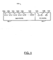
FIG. 1 , a block diagram of asystem 100 is shown in accordance with an embodiment of the present invention. Thesystem 100 may be implemented as an "SAS to FC Switch" or an "STF switch". Thesystem 100 generally comprises a block (or circuit) 102 and a block (or circuit) 104. Thecircuit 102 may include a number ofports 106a-106n. Thecircuit 104 may include a number ofports 108a-108n. The particular number ofports 106a-106n and 108a-108n on thesystem 100 may depend on the particular type of expander and IO chip implemented (to be described in more detail in connection withFIG. 2 ). In one example, the ports may receive one or more data packets in a format compatible with a SAS format. In one example, theports 108a-108n may present and receive one or more second data packets in a format compatible with a fibre channel format. Thesystem 100 converts between the SAS format and the fibre channel format. - Referring to
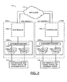
FIG. 2 , a block diagram of asystem 110 is shown. Thesystem 110 illustrates the internal components of aswitch 100a and aswitch 100b. Thecircuit 100a generally comprises a block (or circuit) 120a, a block (or circuit) 122a. Thecircuit 120a may be implemented as a controller circuit. Thecircuit 122a may be implemented as an expander circuit. Thecircuit 122a generally comprises a block (or circuit) 124a and a number of blocks (or circuits) 126a-126n. Thecircuit 124a may provide expander logic. Thecircuits 126a-126n may be implemented as a number of port circuits. - The
expander logic circuit 124a can accommodate one or more SAS initiators along with the target SAS devices. Theexpander logic circuit 124a may be implemented as an IOC chip. Thecircuit 124a is configured to handle SAS initiator traffic when one or more SAS Host Bus Adapters (HBAs) are directly connected to the expander. Theswitch 100a is used to encapsulate SAS frames (or data packets) into one or more FC frames (or packets) so that the encapsulated frames can be transmitted through the SAN. Theswitch 100a may thus be used to implement SAS initiators as part of a SAN. - The
system 110 also comprises a block (or circuit) 112, a block (or circuit) 114 and a block (or circuit) 116. Theblock 112 may represent a SAN cloud. Theblock 114 may be implemented as an SAS initiator, an SAS target port, or one more expander ports. Thecircuit 116 may also be implemented as an SAS initiator, an SAS target port, or one or more expanded ports. - Referring to
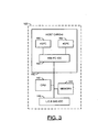
FIG. 3 , a more detailed diagram of thecontroller 120 is shown. Thecontroller 120 generally comprises a block (or circuit) 140, a block (or circuit) 142, a block (or circuit) 144 and a block (or circuit) 146. Thecircuit 140 may be implemented as a host card. Thecircuit 142 may be implemented as a central processing unit (CPU). Thecircuit 144 may be implemented as a memory. Thecircuit 146 may be implemented as a number of SAS I/O circuits. In one example, thecircuit 146 may include a SAS I/O circuit. Thecircuit 140 generally comprises a block (or circuit) 150, a block (or circuit) 152 and a block (or circuit) 154. Thecircuit 150 may be implemented as a fibre channel input circuit. Thecircuit 152 may also be implemented as a fibre channel input circuit. In one example, thecircuit 150 and thecircuit 152 may be implemented as four gigabit fibre channel input circuits. Thecircuit 154 may be implemented as a fibre channel input/output circuit. In one example, thecircuit 154 may be implemented as a four gigabit input/output circuit. Thecontroller 110 may be implemented as a logic device where an FC frame gets converted to SAS data at the SAS IOC chip level. Such a frame may be forwarded to theexpander function circuit 124a which then routes the frame to the appropriate SAS disks/targets. - Referring to
FIG. 4 , a block diagram of asystem 150 is shown. Thesystem 150 illustrates primitive and frame conversion between anSAS device 152, anSTF device 100a', a SAN cloud 112', anSTF device 100b', and anSAS device 154. Thedevice 152 may have a logical connection to theswitch 100a' . The connection between thedevice 152 and theswitch 100a' may be a serial connection, a parallel connection, or other type of sequenced connection. A number of signals (e.g., OPEN, IDLE_DWORDS, SOS/EOF, OPEN, DONE, CLOSE, R_RDY, and HARDREST/OOB) may be transfer between thedevice 152 and thedevice 100a' . Thedevice 154 may have a logical connection to theswitch 100b'. The connection between thedevice 154 and theswitch 100b' may be a serial connection, a parallel connection, or other type of sequenced connection. A number of signals (e.g., OPEN, IDLE_DWORDS, SOS/EOF, OPEN, DONE, CLOSE, R_RDY, and HARDREST/OOB) may be transfer between thedevice 154 and thedevice 100b'. - The
switch 100a' may have a number of inputs/outputs 162a-162n that may connect to the SAN cloud 112'. Theswitch 100b' may have a number of inputs/outputs 164a-164n that may connect to the SAN cloud 112'. In one example, the number of ports in theswitch 100a' and/or theswitch 100b' may be 4 ports. For example, if theswitch 100a' has a dual port HBA switch installed, the 2 ports may be present. If two HBA cards are installed, then 4 ports may be present. The particular number of ports implemented may be varied to meet the design criterial of a particular implementation. - The conversions from SAS to FC (and vice-versa) may take place between the
expander function circuit 124a and the SAS IOC chip. Thesystem 150 illustrates conversion from theSAS device 152 into theSTF switch 100a', then to the SAN cloud 112', then to theSTF switch 100b' , and then to theSAS device 154. A number of signals are shown inside theswitch 100a' and theswitch 100b' that represent fibre channel and SAS primitives. For example, the signal ARB may represent an SAS primitive. In particular, the signal ARB may represent an arbitrate signal (e.g., with parameters 94F0F0 to represent fairness, 94FFFF to fill a word and/or 94yyy to request arbitration for AL_PA=YY). The signal ARB is one example of the format of a FC primitive. The other signals shown (e.g., IDLE, SOF, etc.) may represent similar primitives. For example, the signal DHD may represent a dynamic half-duplex, the signal R_RDY may represent a receiver ready signal, the signal LR may represent a link reset, etc. - Referring to
FIG. 5 a block diagram of asystem 180 is shown. Thesystem 180 illustrates primitive and frame conversion between anSAS device 182, a STF switch 100'', and aFC device 184. A number of signals (e.g., OPEN, IDLE_DWORDS, SOS/EOF, OPEN, DONE, CLOSE, R_RDY, and HARDREST/OOB) may be transmitted between thedevice 182 and the switch 100''. Thedevice 184 may have a logical connection to theswitch 100". - The STF switch 100'' may be used to allow SAS devices (e.g., 182) to talk with FC devices (e.g., 184). The STF switch 100'' may be used to generate/strip certain primitives/commands that the
SAS device 182 does not support. TheFC device 184 generally communicates with theSAS device 182 through a node port on the fabric side. Support for loop devices to participate in such a scenario may be added as a separate module. Also the "No Operational State" and the "Offline State" may be ignored, since the device is not present in such a case. - In one example, the FC payload sizes may need to be limited to 1024 bytes in the example where the SAS does not support 2K data size. In general, FC devices with
Fibre Channel Class 1 andClass 2 compatibility may be implemented in such a configuration. - The Exchange ID and sequence ID may be implemented by (i) ensuring all frames are sent in order [IOD] (e.g., Out of Order delivery may not be supported in a general implementation), (ii) in cases where an FC device is trying to communicate with a SAS device, stripping the Exchange ID and the sequence ID at the STF switch level and forward the stripped packet to the SAS device (e.g., either after buffering the entire data or on a part by part basis), and (iii) in cases where a SAS device is trying to communicate with an FC device, generating the Exchange ID at the STF switch level. The Exchange ID may be 1 and all the sequences mapped to such an ID may be based on a sequence count mapped to a data offset field.
- The
switch 100 may allow SAS devices to be a part of the SAN. An embodiment of the present invention may provide SAN interfaces to both SAS Initiator/Target devices. The distance limitation for SAS devices may be eliminated by implementing a FC sub-system delivery module. Theswitch 100 may be implemented to avoid affecting the overall speed of operation by planning the number of SAS to FC ports implemented on theSTF switch 100. - In one example, the
switch 100 may implement an interface between one or more SAN devices and one or more SAS devices. In one example, one or more SAS device may communicate with one or more FC devices, and vice versa. In one example, one or more SAS devices may talk over a fibre channel network. In another example, one or more iSCSI devices may be connected to a FC network by adding a layer in theswitch 100. For example, an Ethernet Network may be connected to a SAN network. - While the invention has been particularly shown and described with reference to the preferred embodiments thereof, it will be understood by those skilled in the art that various changes in form and details may be made without departing from the scope of the invention.
Claims (11)
- An apparatus comprising:a first circuit (182) configured to present and receive one or more first data packets in a first format compatible with a first protocol of an initiator (114, 116);a second circuit (184) configured to present and receive one or more second data packets in a second format compatible with a second protocol of a storage area network (112); andan expansion circuit (100, 124) configured to convert said first data packets from said first format to said second format such that said initiator is in communication with a storage device in said storage area network,characterised in thatsaid first format comprises a serial attached small computer system interface (SAS) format,said second format comprising a fibre channel (FC) format, andsaid data packets are converted by being encapsulated in fibre channel frames.
- The apparatus according to claim 1, wherein said initiator comprises an SAS initiator.
- The apparatus according to claim 1, wherein said first circuit, said second circuit, and said expansion circuit are implemented in a single network device.
- The apparatus according to claim 1, wherein said expansion circuit is further configured to convert second data packets from said second format to said first format.
- The apparatus according to claim 1, wherein said apparatus is configured to operate as an interface between a SAS device and said storage area network.
- The apparatus according to claim 1, wherein said expansion circuit converts SAS primitives.
- The apparatus according to claim 1, wherein said expansion circuit is directly connected to a plurality of said first circuits.
- A method for converting signals comprising the steps of:(A) presenting and receiving using a first circuit one or more first data packets in a first format compatible with a first protocol of an initiator circuit;(B) presenting and receiving using a second circuit one or more second data packets in a second format compatible with a second protocol of a storage area network; and(C) converting said first data packets from said first format to said second format using an expansion circuit such that said initiator is in communication with a storage device in said storage area network,characterised in that
said first format comprises a serial attached small computer system interface (SAS) format,
said second format comprising a fibre channel (FC) format, and
said data packets are converted by being encapsulated in fibre channel frames. - The method according to claim 8, wherein said initiator comprises an SAS initiator.
- The method according to claim 8, further comprising the step of:converting second data packets from said second format to said first format.
- The method according to claim 8, wherein said first circuit, said second circuit, and said expansion circuit are implemented in a single network device.
Applications Claiming Priority (2)
| Application Number | Priority Date | Filing Date | Title |
|---|---|---|---|
| US8076208P | 2008-07-15 | 2008-07-15 | |
| PCT/US2008/009944 WO2010008366A1 (en) | 2008-07-15 | 2008-08-21 | System to connect a serial scsi array controller to a storage area network |
Publications (3)
| Publication Number | Publication Date |
|---|---|
| EP2300925A1 EP2300925A1 (en) | 2011-03-30 |
| EP2300925A4 EP2300925A4 (en) | 2012-09-19 |
| EP2300925B1 true EP2300925B1 (en) | 2015-04-08 |
Family
ID=41550577
Family Applications (1)
| Application Number | Title | Priority Date | Filing Date |
|---|---|---|---|
| EP08795485.5A Active EP2300925B1 (en) | 2008-07-15 | 2008-08-21 | System to connect a serial scsi array controller to a storage area network |
Country Status (7)
| Country | Link |
|---|---|
| US (1) | US20110090924A1 (en) |
| EP (1) | EP2300925B1 (en) |
| JP (1) | JP2011528465A (en) |
| KR (1) | KR20110040849A (en) |
| CN (1) | CN102089750B (en) |
| TW (1) | TW201003400A (en) |
| WO (1) | WO2010008366A1 (en) |
Families Citing this family (3)
| Publication number | Priority date | Publication date | Assignee | Title |
|---|---|---|---|---|
| US8775774B2 (en) * | 2011-08-26 | 2014-07-08 | Vmware, Inc. | Management system and methods for object storage system |
| RU2474679C1 (en) * | 2012-04-17 | 2013-02-10 | Открытое акционерное общество "Татнефть" им. В.Д. Шашина | Development method of oil deposit with porous-cavernous-fractured manifold |
| US9965197B2 (en) * | 2015-12-15 | 2018-05-08 | Quanta Computer Inc. | System and method for storage area network management using serial attached SCSI expander |
Family Cites Families (18)
| Publication number | Priority date | Publication date | Assignee | Title |
|---|---|---|---|---|
| US6542961B1 (en) * | 1998-12-22 | 2003-04-01 | Hitachi, Ltd. | Disk storage system including a switch |
| US6985983B2 (en) * | 2001-03-01 | 2006-01-10 | Hewlett-Packard Development Company, L.P. | Translating device adapter having a common command set for interfacing multiple types of redundant storage devices to a host processor |
| US6823401B2 (en) * | 2003-01-15 | 2004-11-23 | Hewlett-Packard Development Company, L.P. | Monitor for obtaining device state by intelligent sampling |
| US7376147B2 (en) * | 2003-12-18 | 2008-05-20 | Intel Corporation | Adaptor supporting different protocols |
| US20060004935A1 (en) * | 2004-06-30 | 2006-01-05 | Pak-Lung Seto | Multi-protocol bridge |
| US7296094B2 (en) * | 2004-08-20 | 2007-11-13 | Lsi Corporation | Circuit and method to provide configuration of serial ATA queue depth versus number of devices |
| JP4555029B2 (en) * | 2004-09-01 | 2010-09-29 | 株式会社日立製作所 | Disk array device |
| US7453904B2 (en) * | 2004-10-29 | 2008-11-18 | Intel Corporation | Cut-through communication protocol translation bridge |
| US20070073966A1 (en) * | 2005-09-23 | 2007-03-29 | Corbin John R | Network processor-based storage controller, compute element and method of using same |
| US20070076685A1 (en) * | 2005-09-30 | 2007-04-05 | Pak-Lung Seto | Programmable routing for frame-packet based frame processing |
| US20070121621A1 (en) * | 2005-11-30 | 2007-05-31 | Michael Moretti | Integrated active-active fibre channel capability in SATA and SAS devices |
| JP4775846B2 (en) * | 2006-03-20 | 2011-09-21 | 株式会社日立製作所 | Computer system and method for controlling allocation of physical links |
| US7457902B2 (en) * | 2006-07-21 | 2008-11-25 | Emulex Design & Manufacturing Corporation | Lock and release mechanism for out-of-order frame prevention and support of native command queueing in FC-SATA |
| JP2008027312A (en) * | 2006-07-24 | 2008-02-07 | Hitachi Ltd | Storage device and conversion board |
| US8127089B1 (en) * | 2007-02-14 | 2012-02-28 | Marvell International Ltd. | Hard disk controller which coordinates transmission of buffered data with a host |
| US8156415B1 (en) * | 2007-12-26 | 2012-04-10 | Marvell International Ltd. | Method and system for command queuing in disk drives |
| US8019895B2 (en) * | 2008-03-25 | 2011-09-13 | International Business Machines Corporation | Serial attached SCSI and serial ATA wide port tunnelling through a fibre channel connection |
| US7809865B2 (en) * | 2008-04-25 | 2010-10-05 | International Business Machines Corporation | Apparatus and method to set a communication speed for a SAS/SATA distance extender |
-
2008
- 2008-08-21 WO PCT/US2008/009944 patent/WO2010008366A1/en active Application Filing
- 2008-08-21 JP JP2011518688A patent/JP2011528465A/en active Pending
- 2008-08-21 KR KR1020117001394A patent/KR20110040849A/en not_active Application Discontinuation
- 2008-08-21 EP EP08795485.5A patent/EP2300925B1/en active Active
- 2008-08-21 CN CN200880130322.0A patent/CN102089750B/en active Active
- 2008-10-09 TW TW097138858A patent/TW201003400A/en unknown
-
2010
- 2010-12-16 US US12/969,892 patent/US20110090924A1/en not_active Abandoned
Also Published As
| Publication number | Publication date |
|---|---|
| EP2300925A4 (en) | 2012-09-19 |
| TW201003400A (en) | 2010-01-16 |
| US20110090924A1 (en) | 2011-04-21 |
| CN102089750B (en) | 2014-12-24 |
| EP2300925A1 (en) | 2011-03-30 |
| KR20110040849A (en) | 2011-04-20 |
| CN102089750A (en) | 2011-06-08 |
| JP2011528465A (en) | 2011-11-17 |
| WO2010008366A1 (en) | 2010-01-21 |
Similar Documents
| Publication | Publication Date | Title |
|---|---|---|
| US7917682B2 (en) | Multi-protocol controller that supports PCIe, SAS and enhanced Ethernet | |
| US10437765B2 (en) | Link system for establishing high speed network communications and file transfer between hosts using I/O device links | |
| US7461195B1 (en) | Method and system for dynamically adjusting data transfer rates in PCI-express devices | |
| US7424564B2 (en) | PCI—express slot for coupling plural devices to a host system | |
| US7743178B2 (en) | Method and apparatus for SATA tunneling over fibre channel | |
| EP2316075B1 (en) | Method and apparatus for connecting usb devices to a remote computer | |
| US8700821B2 (en) | Unified multi-transport medium connector architecture | |
| US8694723B2 (en) | Method and system for coupling serial attached SCSI (SAS) devices and internet small computer system internet (iSCSI) devices through single host bus adapter | |
| US20160335209A1 (en) | High-speed data transmission using pcie protocol | |
| CN116501681B (en) | CXL data transmission board card and method for controlling data transmission | |
| CN102185833A (en) | Fiber channel (FC) input/output (I/O) parallel processing method based on field programmable gate array (FPGA) | |
| CN108345555A (en) | Interface bridgt circuit based on high-speed serial communication and its method | |
| CN114168520A (en) | Optical fiber communication bus device, equipment and system | |
| US20050273672A1 (en) | Method and system for efficiently recording processor events in host bus adapters | |
| EP2300925B1 (en) | System to connect a serial scsi array controller to a storage area network | |
| WO2006019770A2 (en) | System and method for transmitting data in storage controllers | |
| EP1810161A1 (en) | Method and system for optimizing data transfer in networks | |
| US7366802B2 (en) | Method in a frame based system for reserving a plurality of buffers based on a selected communication protocol | |
| JP4432388B2 (en) | I / O controller | |
| EP1794953B1 (en) | Method and system for using an in-line credit extender with a host bus adapter | |
| JP4930554B2 (en) | I / O controller | |
| US20090234991A1 (en) | Enhanced throughput communication with a peripheral device | |
| WO2024102916A1 (en) | Root complex switching across inter-die data interface to multiple endpoints | |
| CN117971135A (en) | Storage device access method and device, storage medium and electronic device | |
| Elliott | Serial attached SCSI technical overview |
Legal Events
| Date | Code | Title | Description |
|---|---|---|---|
| PUAI | Public reference made under article 153(3) epc to a published international application that has entered the european phase |
Free format text: ORIGINAL CODE: 0009012 |
|
| 17P | Request for examination filed |
Effective date: 20110111 |
|
| AK | Designated contracting states |
Kind code of ref document: A1 Designated state(s): AT BE BG CH CY CZ DE DK EE ES FI FR GB GR HR HU IE IS IT LI LT LU LV MC MT NL NO PL PT RO SE SI SK TR |
|
| AX | Request for extension of the european patent |
Extension state: AL BA MK RS |
|
| DAX | Request for extension of the european patent (deleted) | ||
| REG | Reference to a national code |
Ref country code: DE Ref legal event code: R079 Ref document number: 602008037590 Country of ref document: DE Free format text: PREVIOUS MAIN CLASS: G06F0015160000 Ipc: G06F0013400000 |
|
| A4 | Supplementary search report drawn up and despatched |
Effective date: 20120822 |
|
| RIC1 | Information provided on ipc code assigned before grant |
Ipc: G06F 3/06 20060101ALN20120816BHEP Ipc: H04L 29/08 20060101ALI20120816BHEP Ipc: G06F 13/40 20060101AFI20120816BHEP |
|
| RAP1 | Party data changed (applicant data changed or rights of an application transferred) |
Owner name: NETAPP, INC. |
|
| GRAP | Despatch of communication of intention to grant a patent |
Free format text: ORIGINAL CODE: EPIDOSNIGR1 |
|
| INTG | Intention to grant announced |
Effective date: 20141029 |
|
| GRAS | Grant fee paid |
Free format text: ORIGINAL CODE: EPIDOSNIGR3 |
|
| GRAA | (expected) grant |
Free format text: ORIGINAL CODE: 0009210 |
|
| AK | Designated contracting states |
Kind code of ref document: B1 Designated state(s): AT BE BG CH CY CZ DE DK EE ES FI FR GB GR HR HU IE IS IT LI LT LU LV MC MT NL NO PL PT RO SE SI SK TR |
|
| REG | Reference to a national code |
Ref country code: GB Ref legal event code: FG4D |
|
| REG | Reference to a national code |
Ref country code: CH Ref legal event code: EP |
|
| REG | Reference to a national code |
Ref country code: IE Ref legal event code: FG4D |
|
| REG | Reference to a national code |
Ref country code: AT Ref legal event code: REF Ref document number: 721024 Country of ref document: AT Kind code of ref document: T Effective date: 20150515 |
|
| REG | Reference to a national code |
Ref country code: DE Ref legal event code: R096 Ref document number: 602008037590 Country of ref document: DE Effective date: 20150521 |
|
| REG | Reference to a national code |
Ref country code: AT Ref legal event code: MK05 Ref document number: 721024 Country of ref document: AT Kind code of ref document: T Effective date: 20150408 |
|
| REG | Reference to a national code |
Ref country code: LT Ref legal event code: MG4D |
|
| PG25 | Lapsed in a contracting state [announced via postgrant information from national office to epo] |
Ref country code: PT Free format text: LAPSE BECAUSE OF FAILURE TO SUBMIT A TRANSLATION OF THE DESCRIPTION OR TO PAY THE FEE WITHIN THE PRESCRIBED TIME-LIMIT Effective date: 20150810 Ref country code: FI Free format text: LAPSE BECAUSE OF FAILURE TO SUBMIT A TRANSLATION OF THE DESCRIPTION OR TO PAY THE FEE WITHIN THE PRESCRIBED TIME-LIMIT Effective date: 20150408 Ref country code: NO Free format text: LAPSE BECAUSE OF FAILURE TO SUBMIT A TRANSLATION OF THE DESCRIPTION OR TO PAY THE FEE WITHIN THE PRESCRIBED TIME-LIMIT Effective date: 20150708 Ref country code: ES Free format text: LAPSE BECAUSE OF FAILURE TO SUBMIT A TRANSLATION OF THE DESCRIPTION OR TO PAY THE FEE WITHIN THE PRESCRIBED TIME-LIMIT Effective date: 20150408 Ref country code: LT Free format text: LAPSE BECAUSE OF FAILURE TO SUBMIT A TRANSLATION OF THE DESCRIPTION OR TO PAY THE FEE WITHIN THE PRESCRIBED TIME-LIMIT Effective date: 20150408 Ref country code: HR Free format text: LAPSE BECAUSE OF FAILURE TO SUBMIT A TRANSLATION OF THE DESCRIPTION OR TO PAY THE FEE WITHIN THE PRESCRIBED TIME-LIMIT Effective date: 20150408 |
|
| PG25 | Lapsed in a contracting state [announced via postgrant information from national office to epo] |
Ref country code: AT Free format text: LAPSE BECAUSE OF FAILURE TO SUBMIT A TRANSLATION OF THE DESCRIPTION OR TO PAY THE FEE WITHIN THE PRESCRIBED TIME-LIMIT Effective date: 20150408 Ref country code: LV Free format text: LAPSE BECAUSE OF FAILURE TO SUBMIT A TRANSLATION OF THE DESCRIPTION OR TO PAY THE FEE WITHIN THE PRESCRIBED TIME-LIMIT Effective date: 20150408 Ref country code: GR Free format text: LAPSE BECAUSE OF FAILURE TO SUBMIT A TRANSLATION OF THE DESCRIPTION OR TO PAY THE FEE WITHIN THE PRESCRIBED TIME-LIMIT Effective date: 20150709 Ref country code: IS Free format text: LAPSE BECAUSE OF FAILURE TO SUBMIT A TRANSLATION OF THE DESCRIPTION OR TO PAY THE FEE WITHIN THE PRESCRIBED TIME-LIMIT Effective date: 20150808 |
|
| REG | Reference to a national code |
Ref country code: DE Ref legal event code: R097 Ref document number: 602008037590 Country of ref document: DE |
|
| PG25 | Lapsed in a contracting state [announced via postgrant information from national office to epo] |
Ref country code: DK Free format text: LAPSE BECAUSE OF FAILURE TO SUBMIT A TRANSLATION OF THE DESCRIPTION OR TO PAY THE FEE WITHIN THE PRESCRIBED TIME-LIMIT Effective date: 20150408 Ref country code: EE Free format text: LAPSE BECAUSE OF FAILURE TO SUBMIT A TRANSLATION OF THE DESCRIPTION OR TO PAY THE FEE WITHIN THE PRESCRIBED TIME-LIMIT Effective date: 20150408 |
|
| PLBE | No opposition filed within time limit |
Free format text: ORIGINAL CODE: 0009261 |
|
| STAA | Information on the status of an ep patent application or granted ep patent |
Free format text: STATUS: NO OPPOSITION FILED WITHIN TIME LIMIT |
|
| PG25 | Lapsed in a contracting state [announced via postgrant information from national office to epo] |
Ref country code: SK Free format text: LAPSE BECAUSE OF FAILURE TO SUBMIT A TRANSLATION OF THE DESCRIPTION OR TO PAY THE FEE WITHIN THE PRESCRIBED TIME-LIMIT Effective date: 20150408 Ref country code: CZ Free format text: LAPSE BECAUSE OF FAILURE TO SUBMIT A TRANSLATION OF THE DESCRIPTION OR TO PAY THE FEE WITHIN THE PRESCRIBED TIME-LIMIT Effective date: 20150408 Ref country code: RO Free format text: LAPSE BECAUSE OF NON-PAYMENT OF DUE FEES Effective date: 20150408 Ref country code: PL Free format text: LAPSE BECAUSE OF FAILURE TO SUBMIT A TRANSLATION OF THE DESCRIPTION OR TO PAY THE FEE WITHIN THE PRESCRIBED TIME-LIMIT Effective date: 20150408 |
|
| 26N | No opposition filed |
Effective date: 20160111 |
|
| PG25 | Lapsed in a contracting state [announced via postgrant information from national office to epo] |
Ref country code: MC Free format text: LAPSE BECAUSE OF FAILURE TO SUBMIT A TRANSLATION OF THE DESCRIPTION OR TO PAY THE FEE WITHIN THE PRESCRIBED TIME-LIMIT Effective date: 20150408 Ref country code: LU Free format text: LAPSE BECAUSE OF FAILURE TO SUBMIT A TRANSLATION OF THE DESCRIPTION OR TO PAY THE FEE WITHIN THE PRESCRIBED TIME-LIMIT Effective date: 20150821 |
|
| REG | Reference to a national code |
Ref country code: CH Ref legal event code: PL |
|
| PG25 | Lapsed in a contracting state [announced via postgrant information from national office to epo] |
Ref country code: IT Free format text: LAPSE BECAUSE OF FAILURE TO SUBMIT A TRANSLATION OF THE DESCRIPTION OR TO PAY THE FEE WITHIN THE PRESCRIBED TIME-LIMIT Effective date: 20150408 Ref country code: CH Free format text: LAPSE BECAUSE OF NON-PAYMENT OF DUE FEES Effective date: 20150831 Ref country code: LI Free format text: LAPSE BECAUSE OF NON-PAYMENT OF DUE FEES Effective date: 20150831 |
|
| PG25 | Lapsed in a contracting state [announced via postgrant information from national office to epo] |
Ref country code: SI Free format text: LAPSE BECAUSE OF FAILURE TO SUBMIT A TRANSLATION OF THE DESCRIPTION OR TO PAY THE FEE WITHIN THE PRESCRIBED TIME-LIMIT Effective date: 20150408 |
|
| REG | Reference to a national code |
Ref country code: IE Ref legal event code: MM4A |
|
| REG | Reference to a national code |
Ref country code: FR Ref legal event code: ST Effective date: 20160429 |
|
| PG25 | Lapsed in a contracting state [announced via postgrant information from national office to epo] |
Ref country code: IE Free format text: LAPSE BECAUSE OF NON-PAYMENT OF DUE FEES Effective date: 20150821 |
|
| PG25 | Lapsed in a contracting state [announced via postgrant information from national office to epo] |
Ref country code: FR Free format text: LAPSE BECAUSE OF NON-PAYMENT OF DUE FEES Effective date: 20150831 Ref country code: BE Free format text: LAPSE BECAUSE OF FAILURE TO SUBMIT A TRANSLATION OF THE DESCRIPTION OR TO PAY THE FEE WITHIN THE PRESCRIBED TIME-LIMIT Effective date: 20150408 |
|
| PG25 | Lapsed in a contracting state [announced via postgrant information from national office to epo] |
Ref country code: MT Free format text: LAPSE BECAUSE OF FAILURE TO SUBMIT A TRANSLATION OF THE DESCRIPTION OR TO PAY THE FEE WITHIN THE PRESCRIBED TIME-LIMIT Effective date: 20150408 |
|
| PG25 | Lapsed in a contracting state [announced via postgrant information from national office to epo] |
Ref country code: HU Free format text: LAPSE BECAUSE OF FAILURE TO SUBMIT A TRANSLATION OF THE DESCRIPTION OR TO PAY THE FEE WITHIN THE PRESCRIBED TIME-LIMIT; INVALID AB INITIO Effective date: 20080821 Ref country code: BG Free format text: LAPSE BECAUSE OF FAILURE TO SUBMIT A TRANSLATION OF THE DESCRIPTION OR TO PAY THE FEE WITHIN THE PRESCRIBED TIME-LIMIT Effective date: 20150408 |
|
| PG25 | Lapsed in a contracting state [announced via postgrant information from national office to epo] |
Ref country code: CY Free format text: LAPSE BECAUSE OF FAILURE TO SUBMIT A TRANSLATION OF THE DESCRIPTION OR TO PAY THE FEE WITHIN THE PRESCRIBED TIME-LIMIT Effective date: 20150408 Ref country code: SE Free format text: LAPSE BECAUSE OF FAILURE TO SUBMIT A TRANSLATION OF THE DESCRIPTION OR TO PAY THE FEE WITHIN THE PRESCRIBED TIME-LIMIT Effective date: 20150408 |
|
| PG25 | Lapsed in a contracting state [announced via postgrant information from national office to epo] |
Ref country code: TR Free format text: LAPSE BECAUSE OF FAILURE TO SUBMIT A TRANSLATION OF THE DESCRIPTION OR TO PAY THE FEE WITHIN THE PRESCRIBED TIME-LIMIT Effective date: 20150408 |
|
| PGFP | Annual fee paid to national office [announced via postgrant information from national office to epo] |
Ref country code: NL Payment date: 20170826 Year of fee payment: 10 |
|
| PGFP | Annual fee paid to national office [announced via postgrant information from national office to epo] |
Ref country code: ES Payment date: 20170601 Year of fee payment: 9 |
|
| REG | Reference to a national code |
Ref country code: NL Ref legal event code: MM Effective date: 20180901 |
|
| GBPC | Gb: european patent ceased through non-payment of renewal fee |
Effective date: 20180821 |
|
| PG25 | Lapsed in a contracting state [announced via postgrant information from national office to epo] |
Ref country code: NL Free format text: LAPSE BECAUSE OF NON-PAYMENT OF DUE FEES Effective date: 20180901 |
|
| PG25 | Lapsed in a contracting state [announced via postgrant information from national office to epo] |
Ref country code: GB Free format text: LAPSE BECAUSE OF NON-PAYMENT OF DUE FEES Effective date: 20180821 |
|
| REG | Reference to a national code |
Ref country code: DE Ref legal event code: R082 Ref document number: 602008037590 Country of ref document: DE Representative=s name: D YOUNG & CO LLP, DE |
|
| P01 | Opt-out of the competence of the unified patent court (upc) registered |
Effective date: 20230523 |
|
| PGFP | Annual fee paid to national office [announced via postgrant information from national office to epo] |
Ref country code: DE Payment date: 20230829 Year of fee payment: 16 |