EP2299723A1 - Video display apparatus and video display method - Google Patents
Video display apparatus and video display method Download PDFInfo
- Publication number
- EP2299723A1 EP2299723A1 EP10159794A EP10159794A EP2299723A1 EP 2299723 A1 EP2299723 A1 EP 2299723A1 EP 10159794 A EP10159794 A EP 10159794A EP 10159794 A EP10159794 A EP 10159794A EP 2299723 A1 EP2299723 A1 EP 2299723A1
- Authority
- EP
- European Patent Office
- Prior art keywords
- time
- determining module
- color temperature
- video
- video display
- Prior art date
- Legal status (The legal status is an assumption and is not a legal conclusion. Google has not performed a legal analysis and makes no representation as to the accuracy of the status listed.)
- Withdrawn
Links
- 238000000034 method Methods 0.000 title claims description 9
- 230000005236 sound signal Effects 0.000 description 9
- 230000000875 corresponding effect Effects 0.000 description 7
- 230000001276 controlling effect Effects 0.000 description 4
- 238000010586 diagram Methods 0.000 description 4
- 230000008569 process Effects 0.000 description 4
- 238000012986 modification Methods 0.000 description 3
- 230000004048 modification Effects 0.000 description 3
- 238000006243 chemical reaction Methods 0.000 description 2
- 230000006870 function Effects 0.000 description 2
- 238000003672 processing method Methods 0.000 description 2
- 230000008859 change Effects 0.000 description 1
- 230000002596 correlated effect Effects 0.000 description 1
- 239000004973 liquid crystal related substance Substances 0.000 description 1
- 230000004044 response Effects 0.000 description 1
Images


Classifications
-
- H—ELECTRICITY
- H04—ELECTRIC COMMUNICATION TECHNIQUE
- H04N—PICTORIAL COMMUNICATION, e.g. TELEVISION
- H04N9/00—Details of colour television systems
- H04N9/64—Circuits for processing colour signals
- H04N9/73—Colour balance circuits, e.g. white balance circuits or colour temperature control
-
- G—PHYSICS
- G09—EDUCATION; CRYPTOGRAPHY; DISPLAY; ADVERTISING; SEALS
- G09G—ARRANGEMENTS OR CIRCUITS FOR CONTROL OF INDICATING DEVICES USING STATIC MEANS TO PRESENT VARIABLE INFORMATION
- G09G2320/00—Control of display operating conditions
- G09G2320/06—Adjustment of display parameters
- G09G2320/0666—Adjustment of display parameters for control of colour parameters, e.g. colour temperature
-
- G—PHYSICS
- G09—EDUCATION; CRYPTOGRAPHY; DISPLAY; ADVERTISING; SEALS
- G09G—ARRANGEMENTS OR CIRCUITS FOR CONTROL OF INDICATING DEVICES USING STATIC MEANS TO PRESENT VARIABLE INFORMATION
- G09G2360/00—Aspects of the architecture of display systems
- G09G2360/14—Detecting light within display terminals, e.g. using a single or a plurality of photosensors
- G09G2360/144—Detecting light within display terminals, e.g. using a single or a plurality of photosensors the light being ambient light
Definitions
- the present invention relates to a video display apparatus and a video display method.
- JP-A-2009-31554 discloses a related-art video display apparatus in which a color temperature of a displayed video is corrected according to brightness of a screen of a display unit that is determined according to illuminance of an ambient light of the video display apparatus.
- the video display apparatus disclosed in JP-A-2009-31554 is provided with an illuminance sensor for measuring the illuminance of the ambient light of the video display apparatus and outputting a signal corresponding to the measured illuminance, a luminance determining module for determining luminance of the display unit based on the illuminance measured by the illuminance sensor, a color temperature correcting module for correcting, based on the luminance determined by the luminance determining module, the color temperature by correcting gradation curves to be used for adjustment of RGB gradations of a video signal, and the display unit for displaying the video signal as corrected by the luminance determining module and the color temperature correcting module.
- video can be displayed that has been corrected so as to be suitable for the illuminance of the ambient light and, as a result, the user would feel natural by setting the luminance and the color temperature of video to be high when the illuminance of the ambient light is high and setting the luminance and the color temperature of video to be low when the illuminance is low.
- the related-art video display apparatus corrects the luminance and the color temperature of video according to the illuminance of the ambient light, it cannot accommodate a case that the color temperature of the ambient light varies being affected by external light coming through a window of a room where the video display apparatus is installed, a color scheme of wallpaper or curtains, or some other factor. Therefore, the related-art video display apparatus may not be able to display a video that the user would feel natural because of a difference between a color temperature of the video as an adjustment result of the video display apparatus and a color temperature of the ambient light that the user senses.
- One of objects of the present invention is to provide a video display apparatus and a video display method which displays video that is corrected so as to be suitable for illuminance and a color temperature of an ambient light of the video display apparatus, and that a user who is viewing the video would feel natural.
- a video display apparatus including: a sensor configured to detect a color temperature of an ambient light of the video display apparatus; a determining module configured to determine that a current time is in one of a first time slot which is from a sunrise time to a sunset time and a second time slot which is from the sunset time to the sunrise time based on sunrise/sunset time information to obtain time slot information of the current time; and an image quality controller configured to control image quality of a video signal based on the color temperature and the time slot information.
- a video display method including: detecting a color temperature of an ambient light of the video display apparatus; determining whether a current time is in one of a first time slot from a sunrise time to a sunset time and a second time slot from the sunset time to the sunrise time based on sunrise/sunset time information to obtain time slot information of the current time; and controlling image quality of a video signal based on the color temperature and the time slot information.
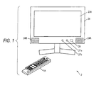
- Fig. 1 is a schematic view showing an appearance of a video display apparatus according to an embodiment of the present invention.
- the video display apparatus 2 is a TV receiver which displays video by receiving digital broadcast waves or the like from the outside via an antenna 20A (see Fig. 2 ) or by receiving a video signal from an external video reproducing apparatus (not shown) such as a hard disk drive (HDD) recorder or a digital versatile disc (DVD) player.
- the video display apparatus 2 is equipped with a display unit 23A which is provided with a liquid crystal display (LCD) panel 231A (see Fig. 2 ) etc.
- LCD liquid crystal display
- an illuminance sensor 27a such as a photodiode which measures illuminance of an ambient light of the video display apparatus 2 and outputs a signal corresponding to the measured illuminance
- a color temperature sensor 27b such as an RGB color sensor which measures a color temperature of the ambient of the video display apparatus 2 and outputs a signal corresponding to the measured color temperature
- a receiver 28 for receiving an operation signal such as a radio frequency (RF) signal or an infrared signal transmitted from a remote controller 1A having a plurality of operation switches.
- RF radio frequency
- the video display apparatus 2 also has, on its back side, antenna terminals, external input terminals, an operation unit consisting of a plurality of switches, etc. (not shown). Furthermore, the video display apparatus 2 has, inside a main body 2A, electronic components such as a central processing unit (CPU) for processing a video signal and an audio signal and controlling respective modules and units, a random access memory (RAM), a read-only memory (ROM), and an HDD.
- CPU central processing unit
- RAM random access memory
- ROM read-only memory
- HDD high-only memory
- the remote controller 1A has, on a front surface of a body of the remote controller 1A, a plurality of operation switches etc. and also has, inside the body, a conversion module for converting an operation on a switch into an operation signal and a transmitting module for sending the operation signal to the video display apparatus 2 in the form of an RF signal, for example.
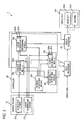
- Fig. 2 is a block diagram showing an exemplary configuration of the video display apparatus 2.
- the video display apparatus 2 is provided with a tuner 20, a signal processor 21, a video processor 22, a display processor 23, an audio processor 24, a controller 25, a storage unit 26, an ambient sensor 27 and the receiver 28, which are connected to each other via a bus 29.
- the tuner 20 selects a signal on a desired channel from broadcast signals transmitted from digital broadcasting stations and received by the antenna 20A, and outputs the desired broadcast signal to the signal processor 21.
- the signal processor 21 is connected to the video processor 22 and the audio processor 24.
- the signal processor 21 separates the broadcast signal received from the tuner 20 into a video signal and an audio signal and outputs the video signal and the audio signal to the video processor 22 and the audio processor 24, respectively.
- the video processor 22 is connected to the display unit 23A via the display processor 23.
- the display processor 23 performs an image quality adjustment on the received video signal and outputs a resulting video signal to the display unit 23A.
- the display processor 23 is provided with a backlight processor 230, a color temperature processor 231, etc. (not shown) for performing display adjustments for the display unit 23A.
- the display unit 23A is provided with a backlight 230A whose luminance is varied by being controlled by an inverter or the like and the LCD panel 231A for displaying video by being illuminated with the backlight 230A.
- the backlight processor 230 adjusts brightness of the LCD panel 231A by varying the luminance of the backlight 230A.
- the color temperature processor 231 adjusts a color temperature of the LCD panel 231A by varying RGB values.
- the audio processor 24 is connected to the speakers 24A and 24B and adjusts sound quality of the received audio signal.
- the video display apparatus 2 is provided with a video analog/digital converter (A/D converter) and an audio A/D converter for receiving a video signal and an audio signal output from a video playback apparatus that is connected to an external input terminal(not shown).
- a video signal and an audio signal (analog signals) that are input to the video A/D converter and the audio A/D converter are converted into digital signals (output signals), respectively, which are output to the video processor 22 and the audio processor 24, respectively.
- the controller has a CPU, and controls the respective units of the video display apparatus 2 via control lines (drawn as solid lines (not arrows) in Fig. 2 ) such as the bus 29.
- the controller 25 operates as a luminance determining module 25a, a color temperature determining module 25b, a density (light and shade) determining module 25c, an image quality determining module 25d, a day/night determining module 25e, etc., which will be described later in detail with reference to Fig. 3 .
- the storage unit 26 stores region information 260 which is information indicating a region where the video display apparatus 2 is placed, sunrise/sunset information 261 which is information of sunrise times and sunset times that are correlated with pieces of region information and dates, video information of programs recorded by the video display apparatus 2, programs for causing the controller 25 to operate as the luminance determining module 25a, the color temperature determining module 25b, the density determining module 25c, the image quality determining module 25d, and the day/night determining module 25e, and other information.
- the region information 260 is set by the user when, for example, the video display apparatus 2 is used for the first time (including a case that the region where the video display apparatus 2 is placed is changed because of a move of the user, for example).
- the ambient sensor 27 consists of a plurality of sensors including the illuminance sensor 27a and the color temperature sensor 271 which are shown in Fig. 1 , and outputs, to the controller 25, signals corresponding to values measured by the illuminance sensor 27a and the color temperature sensor 27b.
- an RGB sensor may be used as the ambient sensor 27, in which case illuminance values of light components in red, green, and blue wavelength ranges are measured, and the illuminance and the color temperature of the ambient light of the video display apparatus 2 are calculated from the measured illuminance values of the three color components.
- the RGB sensor has the functions of both of the illuminance sensor 27a and the color temperature sensor 27b.
- the receiver 28 receives of an operation signal from the remote controller 1A in the form of an RF signal, for example, and outputs the operation signal to the controller 25.
- Fig. 3 is a block diagram showing an exemplary configuration of the control system of the video display apparatus 2.
- the controller 25 operates as the luminance determining module 25a, the color temperature determining module 25b, the density determining module 25c, the image quality determining module 25d, and the day/night determining module 25e.
- the luminance determining module 25a determines luminance of the backlight 230A based on illuminance that is input from the illuminance sensor 27a and a day parameter 250a or a night parameter 251a that is employed according to a day/night determination result which is input from the day/night determining module 25e (described later).
- the backlight 230A is controlled via the backlight processor 230 of the display processor 23.
- the color temperature determining module 25b changes the color temperature of the LCD panel 231A based on the luminance of the backlight 230A that is input from the luminance determining module 25a, a color temperature that is input from the color temperature sensor 27b, and one of a day parameter 250b and a night parameter 251b that is employed according to a day/night determination result that is input from the day/night determining module 25e.
- the LCD panel 231A is controlled via the color temperature processor 231 of the display processor 23.
- the density determining module 25c determines a density (light and shade) of a color signal of a video signal based on the luminance of the backlight 230A that is input from the luminance determining module 25a, the color temperature that is input from the color temperature sensor 27b, and one of a day parameter 250c and a night parameter 251c that is employed according to the day/night determination result that is input from the day/night determining module 25e.
- the density of the color signal of the video signal is changed by the video processor 22.
- the image quality determining module 25d determines a ⁇ -value and sharpness of the video signal based on the luminance of the backlight 230A that is input from the luminance determining module 25a.
- the ⁇ -value and the sharpness of the video signal are changed by the video processor 22.
- the day/night determining module 25e refers to the region information 260 and the sunrise/sunset information 261 which are stored in the storage unit 26, recognizes a current time based on time information that is included in digital broadcast waves received by the tuner 20, and determines whether the current time is in a time slot which is from a sunrise time to a sunset time (hereinafter referred to as a first time slot) or in a time slot which is from the sunset time to the sunrise time (hereinafter referred to as a second time slot). If the current time is in the first time slot, the day/night determining module 25e outputs a signal indicating that the current time is in the first time slot. If the current time is in the second time slot, the day/night determining module 25e outputs a signal indicating that the current time is in the second time slot.
- the user presses a power switch of the remote controller 1A to power-on the video display apparatus 2.
- a control module of the remote controller 1A generates an operation signal for powering-on the video display apparatus 2 and sends the operation signal to the video display apparatus 2 in the form of an RF signal.
- the receiver 28 of the video display apparatus 2 receives the RF signal, the receiver 28 of the video display apparatus 2 outputs a corresponding operation signal to the controller 25, which requests, based on the received operation signal, a power unit (not shown) to power-on the video display apparatus 2.
- the video display apparatus 2 starts to operate in response to the power-on request.
- the tuner 20 receives broadcast signals transmitted from the digital broadcasting stations via the antenna 20A, selects a signal on a desired channel from the received broadcast signals, and outputs the selected signal to the signal processor 21.
- the signal processor 21 separates the broadcast signal received from the tuner 20 into a video signal and an audio signal, and outputs the video signal and the audio signal to the video processor 22 and the audio processor 24, respectively.
- the video processor 22 processes the video signal received from the signal processor 21 under control of the image quality determining module 25d and the density determining module 25c of the controller 25.
- the display processor 23 processes the video signal as processed by the video processor 22 under control of the luminance determining module 25a and the color temperature determining module 25b of the controller 25, and displays a resulting video signal on the display unit 23A.
- the audio processor 24 performs a sound quality adjustment on the audio signal that is input from the signal processor 21, and causes the speakers 24A and 24B to output a sound.
- controller 25 Operations of controller 25 for controlling video processor 22 and display processor 23
- controller 25 for controlling the video processor 22 and the display processor 23, that is, operations of the day/night determining module 25e, the luminance determining module 25a, the color temperature determining module 25b, and the density determining module 25c, will be described below.
- step S3 the day/night determining module 25e determines whether the current time is in the first time slot which is from the sunrise time to the sunset time.
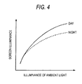
- Fig. 4 is a graph showing an exemplary operation of the luminance determining module 25a of the video display apparatus 2.
- the luminance determining module 25a varies screen luminance of a video to be displayed on the display unit 23A according to the luminance of the ambient light that is measured by the illuminance sensor 27a. More specifically, the luminance determining module 25a varies the screen luminance in the manner represented by a solid line in Fig. 4 by using the day parameter 250a if the determination result of the day/night determining module 25e is that the current time is in the first time slot, and varies the screen luminance in the manner represented by a broken line in Fig. 4 by using the night parameter 251a if the determination result of the day/night determining module 25e is that the current time is in the second time slot.
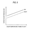
- Fig. 5 is a graph showing an exemplary operation of the color temperature determining module 25b of the video display apparatus 2.
- the color temperature determining module 25b varies a color temperature of a video signal according to the color temperature of the ambient light that is measured by the color temperature sensor 27b. More specifically, the color temperature determining module 25b varies the color temperature in the manner represented by a solid line in Fig. 5 by using the day parameter 250b if the determination result of the day/night determining module 25e is that the current time is in the first time slot, and varies the color temperature in the manner represented by a broken line in Fig. 5 by using the night parameter 251b if the determination result of the day/night determining module 25e is that the current time is in the second time slot.
- the color temperature determining module 25b varies the color temperature of the video signal also according to screen luminance that is determined by the luminance determining module 25a.
- the lines shown in Fig. 5 are ones of a case that the screen luminance is fixed at an arbitrary value.
- Fig. 6 is a graph showing an exemplary operation of the density determining module 25c of the video display apparatus 2.
- the density determining module 25c varies density of a color signal of a video signal according to the color temperature of the ambient light that is measured by the color temperature sensor 27b. More specifically, the density determining module 25c varies the density in the manner represented by a solid line in Fig. 6 by using the day parameter 250c if the determination result of the day/night determining module 25e is that the current time is in the first time slot, and varies the density in the manner represented by a broken line in Fig. 6 by using the night parameter 251e if the determination result of the day/night determining module 25e is that the current time is in the second time slot.
- the density determining module 25c varies the density of the color signal of the video signal also according to the screen luminance that is determined by the luminance determining module 25a.
- the lines shown in Fig. 6 are ones of a case that the screen luminance is fixed at an arbitrary value.
- the image quality determining module 25d determines a ⁇ -value and sharpness of a video signal according to luminance of the backlight 230A that is input from the luminance determining module 25a, and outputs the ⁇ -value and sharpness to the video processor 22.
- video processing and display processing are performed according to the color temperature of the ambient light that is measured by the color temperature sensor 27b in such a manner that a color temperature change due to presence/absence of incidence of external light or some other factor that is determined by the day/night determining module 25e is taken into consideration. Therefore, it is possible to display a video in such a manner that that the user (viewer) would feel the video natural according to the illuminance and the color temperature of the ambient light of the video display apparatus 2.
- the day/night determining module 25e may determine not only whether the current time is in the first time slot or the second time slot but also determine, if it is in the first time slot, whether it is in the morning, around the noon, or in the evening.
- each of the luminance determining module 25a, the color temperature determining module 25b, and the density determining module 25c is configured so as to have parameters corresponding to those time slots.
- a video/display adjustment mode may be provided in which all or part of the illuminance sensor 27a, the color temperature sensor 27b, and the day/night determining module 25e do not function.
- This configuration is effective in, for example, the case where the video display apparatus 2 is placed in a room where there is no difference between a daytime color temperature and a nighttime color temperature, such as a room having no window.
- each of the luminance determining module 25a, the color temperature determining module 25b, the density determining module 25e, and the image quality determining module 25d may be modified according to information other than the (pieces of) information used in the embodiment.
- the processing method may be modified depending on whether or not the video signal source is a movie or the like (e.g., a source that requires 2-3 pull-down conversion).
Landscapes
- Engineering & Computer Science (AREA)
- Multimedia (AREA)
- Signal Processing (AREA)
- Controls And Circuits For Display Device (AREA)
- Processing Of Color Television Signals (AREA)
- Control Of Indicators Other Than Cathode Ray Tubes (AREA)
- Liquid Crystal Display Device Control (AREA)
- Transforming Electric Information Into Light Information (AREA)
Abstract
A video display apparatus includes: a sensor configured to detect a color temperature of an ambient light of the video display apparatus; a determining module configured to determine that a current time is in one of a first time slot which is from a sunrise time to a sunset time and a second time slot which is from the sunset time to the sunrise time based on sunrise/sunsct time information to obtain time slot information of the current time; and an image quality controller configured to control image quality of a video signal based on the color temperature and the time slot information.
Description
- The present disclosure relates to the subject matters contained in Japanese Patent Application No.
2009-211313 filed on September 14, 2009 - The present invention relates to a video display apparatus and a video display method.
-
JP-A-2009-31554 - The video display apparatus disclosed in
JP-A-2009-31554 - However, although the related-art video display apparatus corrects the luminance and the color temperature of video according to the illuminance of the ambient light, it cannot accommodate a case that the color temperature of the ambient light varies being affected by external light coming through a window of a room where the video display apparatus is installed, a color scheme of wallpaper or curtains, or some other factor. Therefore, the related-art video display apparatus may not be able to display a video that the user would feel natural because of a difference between a color temperature of the video as an adjustment result of the video display apparatus and a color temperature of the ambient light that the user senses.
- One of objects of the present invention is to provide a video display apparatus and a video display method which displays video that is corrected so as to be suitable for illuminance and a color temperature of an ambient light of the video display apparatus, and that a user who is viewing the video would feel natural.
- According to an aspect of the present invention, there is provided a video display apparatus including: a sensor configured to detect a color temperature of an ambient light of the video display apparatus; a determining module configured to determine that a current time is in one of a first time slot which is from a sunrise time to a sunset time and a second time slot which is from the sunset time to the sunrise time based on sunrise/sunset time information to obtain time slot information of the current time; and an image quality controller configured to control image quality of a video signal based on the color temperature and the time slot information.
- According to another aspect of the present invention, there is provided a video display method including: detecting a color temperature of an ambient light of the video display apparatus; determining whether a current time is in one of a first time slot from a sunrise time to a sunset time and a second time slot from the sunset time to the sunrise time based on sunrise/sunset time information to obtain time slot information of the current time; and controlling image quality of a video signal based on the color temperature and the time slot information.
- A general configuration that implements the various features of the invention will be described with reference to the drawings. The drawings and the associated descriptions are provided to illustrate embodiments of the invention and not to limit the scope of the invention.
-
Fig. 1 is a schematic view showing an appearance of a video display apparatus according to an embodiment of the present invention. -
Fig. 2 is a block diagram showing an exemplary configuration of the video display apparatus. -
Fig. 3 is a block diagram showing an exemplary configuration of a control system of the video display apparatus. -
Fig. 4 is a graph showing an exemplary operation of a luminance determining module of the video display apparatus. -
Fig. 5 is a graph showing an exemplary operation of a color temperature determining module of the video display apparatus. -
Fig. 6 is a graph showing an exemplary operation of a density determining module of the video display apparatus. -
Fig. 7 is a flowchart showing an exemplary process which is executed by a day/night determining module of the video display apparatus. -
Fig. 1 is a schematic view showing an appearance of a video display apparatus according to an embodiment of the present invention. - The
video display apparatus 2 is a TV receiver which displays video by receiving digital broadcast waves or the like from the outside via anantenna 20A (seeFig. 2 ) or by receiving a video signal from an external video reproducing apparatus (not shown) such as a hard disk drive (HDD) recorder or a digital versatile disc (DVD) player. Thevideo display apparatus 2 is equipped with adisplay unit 23A which is provided with a liquid crystal display (LCD)panel 231A (seeFig. 2 ) etc. and displays video on a front surface of the LCD panel,speakers illuminance sensor 27a such as a photodiode which measures illuminance of an ambient light of thevideo display apparatus 2 and outputs a signal corresponding to the measured illuminance, acolor temperature sensor 27b such as an RGB color sensor which measures a color temperature of the ambient of thevideo display apparatus 2 and outputs a signal corresponding to the measured color temperature, and areceiver 28 for receiving an operation signal such as a radio frequency (RF) signal or an infrared signal transmitted from aremote controller 1A having a plurality of operation switches. - The
video display apparatus 2 also has, on its back side, antenna terminals, external input terminals, an operation unit consisting of a plurality of switches, etc. (not shown). Furthermore, thevideo display apparatus 2 has, inside amain body 2A, electronic components such as a central processing unit (CPU) for processing a video signal and an audio signal and controlling respective modules and units, a random access memory (RAM), a read-only memory (ROM), and an HDD. - The
remote controller 1A has, on a front surface of a body of theremote controller 1A, a plurality of operation switches etc. and also has, inside the body, a conversion module for converting an operation on a switch into an operation signal and a transmitting module for sending the operation signal to thevideo display apparatus 2 in the form of an RF signal, for example. -
Fig. 2 is a block diagram showing an exemplary configuration of thevideo display apparatus 2. - The
video display apparatus 2 is provided with atuner 20, asignal processor 21, avideo processor 22, adisplay processor 23, anaudio processor 24, acontroller 25, astorage unit 26, anambient sensor 27 and thereceiver 28, which are connected to each other via abus 29. - The
tuner 20 selects a signal on a desired channel from broadcast signals transmitted from digital broadcasting stations and received by theantenna 20A, and outputs the desired broadcast signal to thesignal processor 21. - The
signal processor 21 is connected to thevideo processor 22 and theaudio processor 24. Thesignal processor 21 separates the broadcast signal received from thetuner 20 into a video signal and an audio signal and outputs the video signal and the audio signal to thevideo processor 22 and theaudio processor 24, respectively. - The
video processor 22 is connected to thedisplay unit 23A via thedisplay processor 23. - The
display processor 23 performs an image quality adjustment on the received video signal and outputs a resulting video signal to thedisplay unit 23A. Thedisplay processor 23 is provided with abacklight processor 230, acolor temperature processor 231, etc. (not shown) for performing display adjustments for thedisplay unit 23A. Thedisplay unit 23A is provided with abacklight 230A whose luminance is varied by being controlled by an inverter or the like and theLCD panel 231A for displaying video by being illuminated with thebacklight 230A. Thebacklight processor 230 adjusts brightness of theLCD panel 231A by varying the luminance of thebacklight 230A. Thecolor temperature processor 231 adjusts a color temperature of theLCD panel 231A by varying RGB values. - The
audio processor 24 is connected to thespeakers - The
video display apparatus 2 is provided with a video analog/digital converter (A/D converter) and an audio A/D converter for receiving a video signal and an audio signal output from a video playback apparatus that is connected to an external input terminal(not shown). A video signal and an audio signal (analog signals) that are input to the video A/D converter and the audio A/D converter are converted into digital signals (output signals), respectively, which are output to thevideo processor 22 and theaudio processor 24, respectively. - The controller has a CPU, and controls the respective units of the
video display apparatus 2 via control lines (drawn as solid lines (not arrows) inFig. 2 ) such as thebus 29. Thecontroller 25 operates as aluminance determining module 25a, a colortemperature determining module 25b, a density (light and shade) determiningmodule 25c, an imagequality determining module 25d, a day/night determining module 25e, etc., which will be described later in detail with reference toFig. 3 . - The
storage unit 26stores region information 260 which is information indicating a region where thevideo display apparatus 2 is placed, sunrise/sunset information 261 which is information of sunrise times and sunset times that are correlated with pieces of region information and dates, video information of programs recorded by thevideo display apparatus 2, programs for causing thecontroller 25 to operate as theluminance determining module 25a, the colortemperature determining module 25b, thedensity determining module 25c, the imagequality determining module 25d, and the day/night determining module 25e, and other information. Theregion information 260 is set by the user when, for example, thevideo display apparatus 2 is used for the first time (including a case that the region where thevideo display apparatus 2 is placed is changed because of a move of the user, for example). - The
ambient sensor 27 consists of a plurality of sensors including theilluminance sensor 27a and the color temperature sensor 271 which are shown inFig. 1 , and outputs, to thecontroller 25, signals corresponding to values measured by theilluminance sensor 27a and thecolor temperature sensor 27b. Alternatively, only an RGB sensor may be used as theambient sensor 27, in which case illuminance values of light components in red, green, and blue wavelength ranges are measured, and the illuminance and the color temperature of the ambient light of thevideo display apparatus 2 are calculated from the measured illuminance values of the three color components. In this case, the RGB sensor has the functions of both of theilluminance sensor 27a and thecolor temperature sensor 27b. - The
receiver 28 receives of an operation signal from theremote controller 1A in the form of an RF signal, for example, and outputs the operation signal to thecontroller 25. -
Fig. 3 is a block diagram showing an exemplary configuration of the control system of thevideo display apparatus 2. - As described above, the
controller 25 operates as theluminance determining module 25a, the colortemperature determining module 25b, thedensity determining module 25c, the imagequality determining module 25d, and the day/night determining module 25e. - The
luminance determining module 25a determines luminance of thebacklight 230A based on illuminance that is input from theilluminance sensor 27a and aday parameter 250a or anight parameter 251a that is employed according to a day/night determination result which is input from the day/night determining module 25e (described later). Thebacklight 230A is controlled via thebacklight processor 230 of thedisplay processor 23. - The color
temperature determining module 25b changes the color temperature of theLCD panel 231A based on the luminance of thebacklight 230A that is input from theluminance determining module 25a, a color temperature that is input from thecolor temperature sensor 27b, and one of aday parameter 250b and anight parameter 251b that is employed according to a day/night determination result that is input from the day/night determining module 25e. TheLCD panel 231A is controlled via thecolor temperature processor 231 of thedisplay processor 23. - The
density determining module 25c determines a density (light and shade) of a color signal of a video signal based on the luminance of thebacklight 230A that is input from theluminance determining module 25a, the color temperature that is input from thecolor temperature sensor 27b, and one of aday parameter 250c and anight parameter 251c that is employed according to the day/night determination result that is input from the day/night determining module 25e. The density of the color signal of the video signal is changed by thevideo processor 22. - The image
quality determining module 25d determines a γ-value and sharpness of the video signal based on the luminance of thebacklight 230A that is input from theluminance determining module 25a. The γ-value and the sharpness of the video signal are changed by thevideo processor 22. - The day/
night determining module 25e refers to theregion information 260 and the sunrise/sunset information 261 which are stored in thestorage unit 26, recognizes a current time based on time information that is included in digital broadcast waves received by thetuner 20, and determines whether the current time is in a time slot which is from a sunrise time to a sunset time (hereinafter referred to as a first time slot) or in a time slot which is from the sunset time to the sunrise time (hereinafter referred to as a second time slot). If the current time is in the first time slot, the day/night determining module 25e outputs a signal indicating that the current time is in the first time slot. If the current time is in the second time slot, the day/night determining module 25e outputs a signal indicating that the current time is in the second time slot. - An exemplary operation of the
video display apparatus 2 according to the embodiment of the invention will be described below with reference to the drawings. - First, the user presses a power switch of the
remote controller 1A to power-on thevideo display apparatus 2. When the power switch is pressed, a control module of theremote controller 1A generates an operation signal for powering-on thevideo display apparatus 2 and sends the operation signal to thevideo display apparatus 2 in the form of an RF signal. - Receiving the RF signal, the
receiver 28 of thevideo display apparatus 2 outputs a corresponding operation signal to thecontroller 25, which requests, based on the received operation signal, a power unit (not shown) to power-on thevideo display apparatus 2. - The
video display apparatus 2 starts to operate in response to the power-on request. Thetuner 20 receives broadcast signals transmitted from the digital broadcasting stations via theantenna 20A, selects a signal on a desired channel from the received broadcast signals, and outputs the selected signal to thesignal processor 21. - The
signal processor 21 separates the broadcast signal received from thetuner 20 into a video signal and an audio signal, and outputs the video signal and the audio signal to thevideo processor 22 and theaudio processor 24, respectively. - The
video processor 22 processes the video signal received from thesignal processor 21 under control of the imagequality determining module 25d and thedensity determining module 25c of thecontroller 25. - The
display processor 23 processes the video signal as processed by thevideo processor 22 under control of theluminance determining module 25a and the colortemperature determining module 25b of thecontroller 25, and displays a resulting video signal on thedisplay unit 23A. - The
audio processor 24 performs a sound quality adjustment on the audio signal that is input from thesignal processor 21, and causes thespeakers - Operations of the
controller 25 for controlling thevideo processor 22 and thedisplay processor 23, that is, operations of the day/night determining module 25e, theluminance determining module 25a, the colortemperature determining module 25b, and thedensity determining module 25c, will be described below. -
Fig. 7 is a flowchart of an exemplary process which is executed by the day/night determining module 25e of thevideo display apparatus 2. - First, in step S1, the day/
night determining module 25e obtains theregion information 260 from thestorage unit 26 for determining a region where thevideo display apparatus 2 is placed. In step S2, the day/night determining module 25e refers to pieces of information, corresponding to theregion information 260, of the sunrise/sunset information 261 stored in thestorage unit 26 for determining today's sunrise time and a sunset time. - In step S3, the day/
night determining module 25e determines whether the current time is in the first time slot which is from the sunrise time to the sunset time. - If the current time is from the sunrise time to the sunset time (YES in step S3), in step S4, the day/
night determining module 25e outputs a signal indicating that the current time is in the first time slot to theluminance determining module 25a, the colortemperature determining module 25b, and thedensity determining module 25c. If the current time is from the sunset time to the sunrise time (No in step S3), in step S5, the day/night determining module 25e outputs a signal indicating that the current time is in the second time slot to theluminance determining module 25a, the colortemperature determining module 25b, and thedensity determining module 25c. -
Fig. 4 is a graph showing an exemplary operation of theluminance determining module 25a of thevideo display apparatus 2. - The
luminance determining module 25a varies screen luminance of a video to be displayed on thedisplay unit 23A according to the luminance of the ambient light that is measured by theilluminance sensor 27a. More specifically, theluminance determining module 25a varies the screen luminance in the manner represented by a solid line inFig. 4 by using theday parameter 250a if the determination result of the day/night determining module 25e is that the current time is in the first time slot, and varies the screen luminance in the manner represented by a broken line inFig. 4 by using thenight parameter 251a if the determination result of the day/night determining module 25e is that the current time is in the second time slot. -
Fig. 5 is a graph showing an exemplary operation of the colortemperature determining module 25b of thevideo display apparatus 2. - The color
temperature determining module 25b varies a color temperature of a video signal according to the color temperature of the ambient light that is measured by thecolor temperature sensor 27b. More specifically, the colortemperature determining module 25b varies the color temperature in the manner represented by a solid line inFig. 5 by using theday parameter 250b if the determination result of the day/night determining module 25e is that the current time is in the first time slot, and varies the color temperature in the manner represented by a broken line inFig. 5 by using thenight parameter 251b if the determination result of the day/night determining module 25e is that the current time is in the second time slot. The colortemperature determining module 25b varies the color temperature of the video signal also according to screen luminance that is determined by theluminance determining module 25a. The lines shown inFig. 5 are ones of a case that the screen luminance is fixed at an arbitrary value. -
Fig. 6 is a graph showing an exemplary operation of thedensity determining module 25c of thevideo display apparatus 2. - The
density determining module 25c varies density of a color signal of a video signal according to the color temperature of the ambient light that is measured by thecolor temperature sensor 27b. More specifically, thedensity determining module 25c varies the density in the manner represented by a solid line inFig. 6 by using theday parameter 250c if the determination result of the day/night determining module 25e is that the current time is in the first time slot, and varies the density in the manner represented by a broken line inFig. 6 by using the night parameter 251e if the determination result of the day/night determining module 25e is that the current time is in the second time slot. Thedensity determining module 25c varies the density of the color signal of the video signal also according to the screen luminance that is determined by theluminance determining module 25a. The lines shown inFig. 6 are ones of a case that the screen luminance is fixed at an arbitrary value. - The image
quality determining module 25d determines a γ-value and sharpness of a video signal according to luminance of thebacklight 230A that is input from theluminance determining module 25a, and outputs the γ-value and sharpness to thevideo processor 22. - In the above-described embodiment, video processing and display processing are performed according to the color temperature of the ambient light that is measured by the
color temperature sensor 27b in such a manner that a color temperature change due to presence/absence of incidence of external light or some other factor that is determined by the day/night determining module 25e is taken into consideration. Therefore, it is possible to display a video in such a manner that that the user (viewer) would feel the video natural according to the illuminance and the color temperature of the ambient light of thevideo display apparatus 2. - The invention is not limited to the above embodiment, and various modifications are possible without departing from the spirit and scope of the invention. For example, the day/
night determining module 25e may determine not only whether the current time is in the first time slot or the second time slot but also determine, if it is in the first time slot, whether it is in the morning, around the noon, or in the evening. In this case, each of theluminance determining module 25a, the colortemperature determining module 25b, and thedensity determining module 25c is configured so as to have parameters corresponding to those time slots. - A video/display adjustment mode may be provided in which all or part of the
illuminance sensor 27a, thecolor temperature sensor 27b, and the day/night determining module 25e do not function. This configuration is effective in, for example, the case where thevideo display apparatus 2 is placed in a room where there is no difference between a daytime color temperature and a nighttime color temperature, such as a room having no window. - The processing method of each of the
luminance determining module 25a, the colortemperature determining module 25b, thedensity determining module 25e, and the imagequality determining module 25d may be modified according to information other than the (pieces of) information used in the embodiment. For example, the processing method may be modified depending on whether or not the video signal source is a movie or the like (e.g., a source that requires 2-3 pull-down conversion). - Although the embodiment according to the present invention has been described above, the present invention is not limited to the above-mentioned embodiment but can be variously modified.
- Additional advantages and modifications will readily occur to those skilled in the art. Therefore, the invention in its broader aspects is not limited to the specific details and representative embodiments shown and described herein. Accordingly, various modifications may be made without departing from the spirit or scope of the general inventive concept as defined by the appended claims and their equivalents.
Claims (6)
- A video display apparatus comprising:a sensor configured to detect a color temperature of an ambient light the video display apparatus;a determining module configured to determine that a current time is in one of a first time slot which is from a sunrise time to a sunset time and a second time slot which is from the sunset time to the sunrise time based on sunrise/sunset time information to obtain time slot information of the current time; andan image quality controller configured to control image quality of a video signal based on the color temperature and the time slot information.
- The apparatus of claim 1, wherein the image quality controller is configured to control at least one of luminance, color temperature, and density of the video signal.
- The apparatus according of claim 1 or 2, wherein the determining module is configured to obtain the time slot information based on sunrise/sunset time information of a preset region.
- The apparatus of any one of claims 1 to 3, wherein the first time slot and the second time slot are separated into a plurality of subordinate time slots, respectively, and the determining module is configured to determine whether the current time is in one of the plurality of subordinate time slots.
- The apparatus of claim 1, wherein the sensor is configured to detect three-color illuminance values of red, green, and blue light and to calculate the color temperature and illuminance of the ambient light based on the detected three-color illuminance values.
- A video display method comprising:detecting a color temperature of an ambient light the video display apparatus;determining whether a current time is in one of a first time slot from a sunrise time to a sunset time and a second time slot from the sunset time to the sunrise time based on sunrise/sunset time information to obtain time slot information of the current time; andcontrolling image quality of a video signal based on the color temperature and the time slot information.
Applications Claiming Priority (1)
| Application Number | Priority Date | Filing Date | Title |
|---|---|---|---|
| JP2009211313A JP4585601B1 (en) | 2009-09-14 | 2009-09-14 | Video display device and video display method |
Publications (1)
| Publication Number | Publication Date |
|---|---|
| EP2299723A1 true EP2299723A1 (en) | 2011-03-23 |
Family
ID=42245992
Family Applications (1)
| Application Number | Title | Priority Date | Filing Date |
|---|---|---|---|
| EP10159794A Withdrawn EP2299723A1 (en) | 2009-09-14 | 2010-04-13 | Video display apparatus and video display method |
Country Status (2)
| Country | Link |
|---|---|
| EP (1) | EP2299723A1 (en) |
| JP (1) | JP4585601B1 (en) |
Cited By (17)
| Publication number | Priority date | Publication date | Assignee | Title |
|---|---|---|---|---|
| CN104795051A (en) * | 2014-11-17 | 2015-07-22 | 苹果公司 | Ambient light adaptive display |
| CN106205557A (en) * | 2016-09-29 | 2016-12-07 | 北京小米移动软件有限公司 | Screen brightness regulation method and device |
| US9530362B2 (en) | 2014-12-23 | 2016-12-27 | Apple Inc. | Ambient light adaptive displays with paper-like appearance |
| WO2017031237A1 (en) * | 2015-08-17 | 2017-02-23 | Manufacturing Resources International, Inc. | Electronic display with environmental adaptation of display characteristics based on location |
| US9799306B2 (en) | 2011-09-23 | 2017-10-24 | Manufacturing Resources International, Inc. | System and method for environmental adaptation of display characteristics |
| US9924583B2 (en) | 2015-05-14 | 2018-03-20 | Mnaufacturing Resources International, Inc. | Display brightness control based on location data |
| US10354620B2 (en) | 2017-05-12 | 2019-07-16 | Samsung Electronics Co., Ltd. | Electronic apparatus and method for displaying a content screen on the electronic apparatus thereof |
| CN110032351A (en) * | 2019-04-22 | 2019-07-19 | 广东小天才科技有限公司 | Screen blue light adjusting method, device, electronic equipment and storage medium |
| US10440790B2 (en) | 2008-05-21 | 2019-10-08 | Manufacturing Resources International, Inc. | Electronic display system with illumination control |
| US10578658B2 (en) | 2018-05-07 | 2020-03-03 | Manufacturing Resources International, Inc. | System and method for measuring power consumption of an electronic display assembly |
| US10586508B2 (en) | 2016-07-08 | 2020-03-10 | Manufacturing Resources International, Inc. | Controlling display brightness based on image capture device data |
| US10593255B2 (en) | 2015-05-14 | 2020-03-17 | Manufacturing Resources International, Inc. | Electronic display with environmental adaptation of display characteristics based on location |
| US10607520B2 (en) | 2015-05-14 | 2020-03-31 | Manufacturing Resources International, Inc. | Method for environmental adaptation of display characteristics based on location |
| CN110969996A (en) * | 2018-09-30 | 2020-04-07 | 北京奇虎科技有限公司 | Mobile terminal, method and device for adjusting brightness of display screen of mobile terminal and storage medium |
| US10782276B2 (en) | 2018-06-14 | 2020-09-22 | Manufacturing Resources International, Inc. | System and method for detecting gas recirculation or airway occlusion |
| CN114430480A (en) * | 2021-12-30 | 2022-05-03 | 南京巨鲨显示科技有限公司 | Environmental color temperature self-adaptive adjusting method and system for medical display |
| US11526044B2 (en) | 2020-03-27 | 2022-12-13 | Manufacturing Resources International, Inc. | Display unit with orientation based operation |
Families Citing this family (3)
| Publication number | Priority date | Publication date | Assignee | Title |
|---|---|---|---|---|
| JP6094305B2 (en) * | 2013-03-26 | 2017-03-15 | セイコーエプソン株式会社 | Head-mounted display device and method for controlling head-mounted display device |
| JP2014216963A (en) * | 2013-04-26 | 2014-11-17 | シャープ株式会社 | Display device, control method of display device, and control program of display device |
| JP6992053B2 (en) * | 2016-08-16 | 2022-01-13 | 楽天グループ株式会社 | Device case magnet system and method |
Citations (3)
| Publication number | Priority date | Publication date | Assignee | Title |
|---|---|---|---|---|
| JP2009031554A (en) * | 2007-07-27 | 2009-02-12 | Sharp Corp | Video display device and video display method thereof |
| EP2071558A1 (en) * | 2006-09-27 | 2009-06-17 | Sony Corporation | Display apparatus and display method |
| US20090256916A1 (en) * | 2008-04-09 | 2009-10-15 | Canon Kabushiki Kaisha | Display device, broadcast receiving apparatus, display method, and broadcast receiving method |
Family Cites Families (6)
| Publication number | Priority date | Publication date | Assignee | Title |
|---|---|---|---|---|
| JPS62189891A (en) * | 1986-02-14 | 1987-08-19 | Fuji Photo Film Co Ltd | Automatic white balance device |
| JPH10174017A (en) * | 1996-12-16 | 1998-06-26 | Mitsubishi Electric Corp | Television receiver and its color temperature control method |
| JP2001282175A (en) * | 2000-03-31 | 2001-10-12 | Matsushita Electric Ind Co Ltd | Large-sized video display device |
| JP2001296820A (en) * | 2000-04-12 | 2001-10-26 | Matsushita Electric Ind Co Ltd | Led display device |
| JP2003078920A (en) * | 2001-09-05 | 2003-03-14 | Nec Gumma Ltd | Display device |
| JP2003228330A (en) * | 2002-02-01 | 2003-08-15 | Sanyo Electric Co Ltd | Display device |
-
2009
- 2009-09-14 JP JP2009211313A patent/JP4585601B1/en active Active
-
2010
- 2010-04-13 EP EP10159794A patent/EP2299723A1/en not_active Withdrawn
Patent Citations (3)
| Publication number | Priority date | Publication date | Assignee | Title |
|---|---|---|---|---|
| EP2071558A1 (en) * | 2006-09-27 | 2009-06-17 | Sony Corporation | Display apparatus and display method |
| JP2009031554A (en) * | 2007-07-27 | 2009-02-12 | Sharp Corp | Video display device and video display method thereof |
| US20090256916A1 (en) * | 2008-04-09 | 2009-10-15 | Canon Kabushiki Kaisha | Display device, broadcast receiving apparatus, display method, and broadcast receiving method |
Cited By (36)
| Publication number | Priority date | Publication date | Assignee | Title |
|---|---|---|---|---|
| US10440790B2 (en) | 2008-05-21 | 2019-10-08 | Manufacturing Resources International, Inc. | Electronic display system with illumination control |
| US9799306B2 (en) | 2011-09-23 | 2017-10-24 | Manufacturing Resources International, Inc. | System and method for environmental adaptation of display characteristics |
| US10255884B2 (en) | 2011-09-23 | 2019-04-09 | Manufacturing Resources International, Inc. | System and method for environmental adaptation of display characteristics |
| US9947259B2 (en) | 2014-11-17 | 2018-04-17 | Apple Inc. | Ambient light adaptive displays |
| EP3021315A1 (en) * | 2014-11-17 | 2016-05-18 | Apple Inc. | Ambient light adaptive displays |
| US9478157B2 (en) | 2014-11-17 | 2016-10-25 | Apple Inc. | Ambient light adaptive displays |
| CN104795051A (en) * | 2014-11-17 | 2015-07-22 | 苹果公司 | Ambient light adaptive display |
| EP3486895A1 (en) * | 2014-11-17 | 2019-05-22 | Apple Inc. | Ambient light adaptive displays |
| CN104795051B (en) * | 2014-11-17 | 2017-07-07 | 苹果公司 | Ambient light adaptive display |
| US10867578B2 (en) | 2014-12-23 | 2020-12-15 | Apple Inc. | Ambient light adaptive displays with paper-like appearance |
| US9530362B2 (en) | 2014-12-23 | 2016-12-27 | Apple Inc. | Ambient light adaptive displays with paper-like appearance |
| US10412816B2 (en) | 2015-05-14 | 2019-09-10 | Manufacturing Resources International, Inc. | Display brightness control based on location data |
| US10607520B2 (en) | 2015-05-14 | 2020-03-31 | Manufacturing Resources International, Inc. | Method for environmental adaptation of display characteristics based on location |
| US9924583B2 (en) | 2015-05-14 | 2018-03-20 | Mnaufacturing Resources International, Inc. | Display brightness control based on location data |
| US10593255B2 (en) | 2015-05-14 | 2020-03-17 | Manufacturing Resources International, Inc. | Electronic display with environmental adaptation of display characteristics based on location |
| US10321549B2 (en) | 2015-05-14 | 2019-06-11 | Manufacturing Resources International, Inc. | Display brightness control based on location data |
| WO2017031237A1 (en) * | 2015-08-17 | 2017-02-23 | Manufacturing Resources International, Inc. | Electronic display with environmental adaptation of display characteristics based on location |
| US10586508B2 (en) | 2016-07-08 | 2020-03-10 | Manufacturing Resources International, Inc. | Controlling display brightness based on image capture device data |
| CN106205557B (en) * | 2016-09-29 | 2019-08-02 | 北京小米移动软件有限公司 | Screen brightness regulation method and device |
| EP3301664A3 (en) * | 2016-09-29 | 2018-06-13 | Beijing Xiaomi Mobile Software Co., Ltd. | Method and apparatus for adjusting screen brightness |
| CN106205557A (en) * | 2016-09-29 | 2016-12-07 | 北京小米移动软件有限公司 | Screen brightness regulation method and device |
| US10204595B2 (en) | 2016-09-29 | 2019-02-12 | Beijing Xiaomi Mobile Software Co., Ltd. | Methods and devices for adjusting screen brightness |
| US10354620B2 (en) | 2017-05-12 | 2019-07-16 | Samsung Electronics Co., Ltd. | Electronic apparatus and method for displaying a content screen on the electronic apparatus thereof |
| US10867585B2 (en) | 2017-05-12 | 2020-12-15 | Samsung Electronics Co., Ltd. | Electronic apparatus and method for displaying a content screen on the electronic apparatus thereof |
| US11022635B2 (en) | 2018-05-07 | 2021-06-01 | Manufacturing Resources International, Inc. | Measuring power consumption of an electronic display assembly |
| US10578658B2 (en) | 2018-05-07 | 2020-03-03 | Manufacturing Resources International, Inc. | System and method for measuring power consumption of an electronic display assembly |
| US11656255B2 (en) | 2018-05-07 | 2023-05-23 | Manufacturing Resources International, Inc. | Measuring power consumption of a display assembly |
| US10782276B2 (en) | 2018-06-14 | 2020-09-22 | Manufacturing Resources International, Inc. | System and method for detecting gas recirculation or airway occlusion |
| US11293908B2 (en) | 2018-06-14 | 2022-04-05 | Manufacturing Resources International, Inc. | System and method for detecting gas recirculation or airway occlusion |
| US11774428B2 (en) | 2018-06-14 | 2023-10-03 | Manufacturing Resources International, Inc. | System and method for detecting gas recirculation or airway occlusion |
| CN110969996A (en) * | 2018-09-30 | 2020-04-07 | 北京奇虎科技有限公司 | Mobile terminal, method and device for adjusting brightness of display screen of mobile terminal and storage medium |
| CN110032351A (en) * | 2019-04-22 | 2019-07-19 | 广东小天才科技有限公司 | Screen blue light adjusting method, device, electronic equipment and storage medium |
| US11526044B2 (en) | 2020-03-27 | 2022-12-13 | Manufacturing Resources International, Inc. | Display unit with orientation based operation |
| US11815755B2 (en) | 2020-03-27 | 2023-11-14 | Manufacturing Resources International, Inc. | Display unit with orientation based operation |
| CN114430480A (en) * | 2021-12-30 | 2022-05-03 | 南京巨鲨显示科技有限公司 | Environmental color temperature self-adaptive adjusting method and system for medical display |
| CN114430480B (en) * | 2021-12-30 | 2023-12-12 | 南京巨鲨显示科技有限公司 | Environment color temperature self-adaptive adjusting method and system for medical display |
Also Published As
| Publication number | Publication date |
|---|---|
| JP4585601B1 (en) | 2010-11-24 |
| JP2011059543A (en) | 2011-03-24 |
Similar Documents
| Publication | Publication Date | Title |
|---|---|---|
| EP2299723A1 (en) | Video display apparatus and video display method | |
| KR100774203B1 (en) | Control method for display character of television receiver and the television receiver | |
| US8436803B2 (en) | Image display device and image display method | |
| US20090213272A1 (en) | Video processing apparatus and method for processing video signal | |
| US8542182B2 (en) | Video display apparatus and video display method | |
| JP2010124197A (en) | Television device | |
| US8044995B2 (en) | Image processor and method for adjusting image quality | |
| EP3140829A1 (en) | Method and apparatus for adjusting display settings of a display according to ambient lighting | |
| US20100066712A1 (en) | Video processing apparatus and video processing method | |
| JP2009198653A (en) | Video display device and video display method | |
| JP2000115649A (en) | Television receiver | |
| US20110164182A1 (en) | Video Processing Apparatus and Video Processing Method | |
| JP4749839B2 (en) | LCD television | |
| JP2009294296A (en) | Liquid crystal image display device | |
| KR20110001545A (en) | Image display dvic and the method for controlling | |
| JP2011059389A (en) | Video display device | |
| JP2012003201A (en) | Graphic display device | |
| JP4940273B2 (en) | Video display device and video display method | |
| KR20000032178A (en) | Device and method for automatically adjusting screen brightness of tv | |
| US20070296862A1 (en) | Television receiving apparatus | |
| US20110164183A1 (en) | Video processing apparatus and video processing method | |
| KR0153092B1 (en) | Color level variable control apparatus of a television | |
| KR930007373B1 (en) | Auto picture level adjusting method | |
| KR20080067240A (en) | Method for power saving of digital television | |
| KR20040009885A (en) | Video displaying device capable of adjusting picture for DTV signal and a method of adjusting picture thereof |
Legal Events
| Date | Code | Title | Description |
|---|---|---|---|
| PUAI | Public reference made under article 153(3) epc to a published international application that has entered the european phase |
Free format text: ORIGINAL CODE: 0009012 |
|
| 17P | Request for examination filed |
Effective date: 20100413 |
|
| AK | Designated contracting states |
Kind code of ref document: A1 Designated state(s): AT BE BG CH CY CZ DE DK EE ES FI FR GB GR HR HU IE IS IT LI LT LU LV MC MK MT NL NO PL PT RO SE SI SK SM TR |
|
| AX | Request for extension of the european patent |
Extension state: AL BA ME RS |
|
| STAA | Information on the status of an ep patent application or granted ep patent |
Free format text: STATUS: THE APPLICATION HAS BEEN WITHDRAWN |
|
| 18W | Application withdrawn |
Effective date: 20160309 |