EP2298242B1 - Assembly for use with a intraocular lens - Google Patents
Assembly for use with a intraocular lens Download PDFInfo
- Publication number
- EP2298242B1 EP2298242B1 EP09758358.7A EP09758358A EP2298242B1 EP 2298242 B1 EP2298242 B1 EP 2298242B1 EP 09758358 A EP09758358 A EP 09758358A EP 2298242 B1 EP2298242 B1 EP 2298242B1
- Authority
- EP
- European Patent Office
- Prior art keywords
- intraocular lens
- protrusion
- lens
- cartridge
- casing
- Prior art date
- Legal status (The legal status is an assumption and is not a legal conclusion. Google has not performed a legal analysis and makes no representation as to the accuracy of the status listed.)
- Active
Links
Images


Classifications
-
- A—HUMAN NECESSITIES
- A61—MEDICAL OR VETERINARY SCIENCE; HYGIENE
- A61F—FILTERS IMPLANTABLE INTO BLOOD VESSELS; PROSTHESES; DEVICES PROVIDING PATENCY TO, OR PREVENTING COLLAPSING OF, TUBULAR STRUCTURES OF THE BODY, e.g. STENTS; ORTHOPAEDIC, NURSING OR CONTRACEPTIVE DEVICES; FOMENTATION; TREATMENT OR PROTECTION OF EYES OR EARS; BANDAGES, DRESSINGS OR ABSORBENT PADS; FIRST-AID KITS
- A61F2/00—Filters implantable into blood vessels; Prostheses, i.e. artificial substitutes or replacements for parts of the body; Appliances for connecting them with the body; Devices providing patency to, or preventing collapsing of, tubular structures of the body, e.g. stents
- A61F2/02—Prostheses implantable into the body
- A61F2/14—Eye parts, e.g. lenses, corneal implants; Implanting instruments specially adapted therefor; Artificial eyes
- A61F2/16—Intraocular lenses
- A61F2/1662—Instruments for inserting intraocular lenses into the eye
- A61F2/1678—Instruments for inserting intraocular lenses into the eye with a separate cartridge or other lens setting part for storage of a lens, e.g. preloadable for shipping
-
- A—HUMAN NECESSITIES
- A61—MEDICAL OR VETERINARY SCIENCE; HYGIENE
- A61F—FILTERS IMPLANTABLE INTO BLOOD VESSELS; PROSTHESES; DEVICES PROVIDING PATENCY TO, OR PREVENTING COLLAPSING OF, TUBULAR STRUCTURES OF THE BODY, e.g. STENTS; ORTHOPAEDIC, NURSING OR CONTRACEPTIVE DEVICES; FOMENTATION; TREATMENT OR PROTECTION OF EYES OR EARS; BANDAGES, DRESSINGS OR ABSORBENT PADS; FIRST-AID KITS
- A61F2/00—Filters implantable into blood vessels; Prostheses, i.e. artificial substitutes or replacements for parts of the body; Appliances for connecting them with the body; Devices providing patency to, or preventing collapsing of, tubular structures of the body, e.g. stents
- A61F2/02—Prostheses implantable into the body
- A61F2/14—Eye parts, e.g. lenses, corneal implants; Implanting instruments specially adapted therefor; Artificial eyes
- A61F2/16—Intraocular lenses
- A61F2/1662—Instruments for inserting intraocular lenses into the eye
- A61F2/1664—Instruments for inserting intraocular lenses into the eye for manual insertion during surgery, e.g. forceps-like instruments
-
- A—HUMAN NECESSITIES
- A61—MEDICAL OR VETERINARY SCIENCE; HYGIENE
- A61F—FILTERS IMPLANTABLE INTO BLOOD VESSELS; PROSTHESES; DEVICES PROVIDING PATENCY TO, OR PREVENTING COLLAPSING OF, TUBULAR STRUCTURES OF THE BODY, e.g. STENTS; ORTHOPAEDIC, NURSING OR CONTRACEPTIVE DEVICES; FOMENTATION; TREATMENT OR PROTECTION OF EYES OR EARS; BANDAGES, DRESSINGS OR ABSORBENT PADS; FIRST-AID KITS
- A61F2/00—Filters implantable into blood vessels; Prostheses, i.e. artificial substitutes or replacements for parts of the body; Appliances for connecting them with the body; Devices providing patency to, or preventing collapsing of, tubular structures of the body, e.g. stents
- A61F2/02—Prostheses implantable into the body
- A61F2/14—Eye parts, e.g. lenses, corneal implants; Implanting instruments specially adapted therefor; Artificial eyes
- A61F2/16—Intraocular lenses
- A61F2/1662—Instruments for inserting intraocular lenses into the eye
- A61F2/167—Instruments for inserting intraocular lenses into the eye with pushable plungers
-
- A—HUMAN NECESSITIES
- A61—MEDICAL OR VETERINARY SCIENCE; HYGIENE
- A61F—FILTERS IMPLANTABLE INTO BLOOD VESSELS; PROSTHESES; DEVICES PROVIDING PATENCY TO, OR PREVENTING COLLAPSING OF, TUBULAR STRUCTURES OF THE BODY, e.g. STENTS; ORTHOPAEDIC, NURSING OR CONTRACEPTIVE DEVICES; FOMENTATION; TREATMENT OR PROTECTION OF EYES OR EARS; BANDAGES, DRESSINGS OR ABSORBENT PADS; FIRST-AID KITS
- A61F2/00—Filters implantable into blood vessels; Prostheses, i.e. artificial substitutes or replacements for parts of the body; Appliances for connecting them with the body; Devices providing patency to, or preventing collapsing of, tubular structures of the body, e.g. stents
- A61F2/02—Prostheses implantable into the body
- A61F2/14—Eye parts, e.g. lenses, corneal implants; Implanting instruments specially adapted therefor; Artificial eyes
- A61F2/16—Intraocular lenses
- A61F2/1691—Packages or dispensers for intraocular lenses
Definitions
- This invention relates to an intraocular lens insertion device and a cartridge thereof that are used when implanting an intraocular lens into an aphakic eye after a cataract operation.
- Intraocular lenses include: a hard intraocular lens whose optical portion is made of a hard material such as PMMA (polymethylmethacrylate), and a soft intraocular lens which is made of a soft material such as silicone elastomer, soft acrylic, or hydrogel.
- the intraocular lens When using a hard intraocular lens, the intraocular lens must be inserted through an incision formed in the cornea or sclera that is of the same or slightly wider width than the diameter of the optical portion. On the other hand, when using a soft intraocular lens, folding of the optical portion allows the intraocular lens to be inserted into the eye through an incision smaller than the diameter of the optical portion.
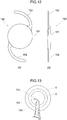
- FIG. 12 shows a soft intraocular lens of this kind.
- a front view is shown in FIG.12(A) and a side view is shown in FIG.12(B) .
- a soft intraocular lens 100 of this kind is formed in a flat circular shape and comprises an optical portion 101 serving as a crystalline lens in an eyeball and two supporting portions 102, 102 formed in a linear shape. These two supporting portions 102, 102 are provided at two symmetrically opposite sections on the circumference of the optical portion 101.
- the supporting portions 102, 102 are extended in the form of a circular arc in such a manner as gradually departing away from the outer fringe of the optical portion 101 at a curvature slightly larger than that of the outer fringe of the optical portion 101
- the soft intraocular lens 100 of this kind is designed so as to be able to be inserted through a small incision into an eye after the optical portion 101 thereof is folded in two by an intraocular lens insertion device disclosed, for example, in Intl Application Publication Pamphlet of WO2006/090531 , Japanese Unexamined Patent Application Publication No. 2004-351196 or in Advanced Medical Optics Inc. of WO 2007/087641 A2 . Further, WO 2007/087641 A2 discloses an intraocular lens insertion device comprising a cylindrical insertion portion to place therein an intraocular lens having one or more supporting portions provided on an outer fringe of an optical portion.
- the intraocular lens insertion device pushing out the intraocular lens by a plunger and releasing the intraocular lens to an outside from a noozle portion of the cylindrical insertion portion.
- the intraocular lens may be transferred from a storage case to an inserter handpiece and/or inserter cartridge in preparation for placement into the eye of a subject.
- an object of the present invention to provide an intraocular lens insertion device and cartridge thereof which enable an intraocular lens to be inserted into an eye more easily and more stably as compared to by the conventional ones.
- the protrusion is provided in the casing, and thus even thin and short protrusion can be easily engaged or disengaged by just attaching or detaching the casing to or from the cartridge.
- reference numeral 1 indicates an intraocular lens insertion device as a whole.
- the intraocular lens insertion device 1 comprises a cartridge 2 and an insertion device body 3 having a plunger 4.
- the cartridge 2 is attached to an attaching portion 3a of the insertion device body 3.
- the intraocular lens insertion device 1 has an intraocular lens 100 installed in the cartridge 2, and is structured so as to be able to discharge the intraocular lens 100 from the tip end of the cartridge 2 into an eye by pushing out the intraocular lens 100 in the lens-advancing direction x (i.e., the direction of an arrow x, or an anterior direction in the lens-advancing axis A) using the plunger 4.
- the lens-advancing direction x i.e., the direction of an arrow x, or an anterior direction in the lens-advancing axis A
- the cartridge 2 attached to the insertion device body 3 as referred to above is described further below.
- the cartridge 2 serving as a cylindrical or tubular insertion portion, comprises a cartridge body 14 composed of a lens insertion opening 10, a lens placement portion 11, a transition portion 12 and a nozzle 13 in sequence, along the lens-advancing axis A; and wings 15, 15 extending from both side faces of the cartridge body 14 along the lateral direction y perpendicular to the lens-advancing direction x.
- the lens insertion opening 10 is provided with an insertion groove 16 formed on upper and lower surfaces by being cut out in the lens-advancing direction x.
- the lens placement portion 11 is provided anterior to the lens insertion opening 10 with respect to the lens-advancing axis A
- the transition portion 12 is provided anterior to the lens placement portion 11 with respect to the lens-advancing axis A.
- An inner wall of the transition portion 12 is formed in the shape of a mortar gradually tapering toward the tip end thereof, and the tip end of the transition portion 12 is communicated with the nozzle 13.
- the cartridge body 14 is formed such that the intraocular lens 100 can be moved from the lens placement portion 11 through the transition portion 12 to the nozzle 13 in sequence by being pushed with the plunger 4 in the lens-advancing direction x. Also, the cartridge body 14 is formed so as to be able to discharge the intraocular lens pushed by the plunger 4 into the eye from a discharge port 13a of the nozzle 13.
- the nozzle 13 is contoured so that it can be inserted into an incision (not shown).
- the cartridge 2 of the present invention is provided with a protrusion insertion hole 20 formed so as to penetrate the thickness thereof in the vicinity of the lens placement portion 11 toward the vertical direction z perpendicular to both the lens-advancing direction x and the lateral direction y, as illustrated in FIGs. 2(A) and 2(B) .
- the protrusion insertion hole 20 is, as shown in FIG.2(A) , shifted toward one side relative to the lens-advancing axis A (in this case, downward) and is formed so as to allow a hole region thereof to cross only a part of a transition space in which the intraocular lens 100 moves.
- the cartridge 2 is formed so as to be detachable from a casing 22 on which a protrusion 21 is vertically provided so that the protrusion 21 may be inserted into the protrusion insertion hole 20 by attaching the cartridge 2 to the casing.
- the protrusion 21 is allowed to pass through a part of the transition space in the cartridge 2 so that the tip end of the protrusion 21 is exposed to the outside.
- the casing 22 includes a casing main body 23 to which the cartridge 2 is attached, and the casing main body 23 is provided with fixing claws 24, 24 for fixedly attaching the cartridge 2 to the casing main body 23 and the said protrusion 21 that is to be inserted into the protrusion insertion hole 20 at the time of the attachment of the cartridge 2.
- the casing main body 23 is integrally formed of a synthetic resin material such as a plastic material, and comprises a tip-side holding portion 25 holding the transition portion 12 and nozzle 13 of the cartridge 2; and an insertion-side holding portion 26 holding the lens insertion opening 10, lens placement portion 11 and wings 15, 15 of the cartridge 2.
- the tip-side holding portion 25 includes a base plate 27 having a bell shape as a whole such that its side faces are slightly concavely curved toward the inside at their central portions, and a wall portion 28 vertically provided along the outer fringe of the base plate 27.
- the tip-side holding portion 25 is formed such that the side faces of the wall portion 28 are also slightly concavely curved toward the inside at their central portions, corresponding to the contour of the base plate 27, so that it may be easily held between user's thumb and index finger.
- the tip-side holding portion 25 includes a cutout portion 30 provided at a wall portion 29 on a proximal portion thereof adjacent to the insertion-side holding portion 26.
- the cutout portion 30 is formed by being cut out in a concavely curved manner, corresponding to the contour of the transition portion 12 of the cartridge 2, thereby enabling the transition portion 12 of the cartridge 2 to be placed on the cutout portion 30.
- the tip-side holding portion 25 includes an inner wall portion 31 spaced a distance away from the wall portion 29 on the proximal portion, extending toward the lateral direction y.
- the inner wall portion 31 is cut out in a concavely curved manner, corresponding to the contour of the transition portion 12 of the cartridge 2, thereby enabling the transition portion 12 of the cartridge 2 to be placed on a cutout portion 32 thereof as well.
- the tip-side holding portion 25 includes the two fixing claws 24, 24 opposed to each other, at given positions on the base plate 27 between the wall portion 29 on the proximal side and the inner wall portion 31.
- the two fixing claws 24, 24 have elastic retention capacity as a result of selecting a synthetic resin material as a material, thereby expanding the fixing claws 24, 24 toward the lateral direction y by an external force applied at the time when the cartridge 2 is placed on the casing 22 and returning the fixing claws 24, 24 to an original state at the time when the external force is no longer applied.
- the fixing claws 24, 24 are each provided, at their tip end, with an engaging claw 24a folded back toward the upper face side of the cartridge 2, so that the cartridge 2 may be fitted and held in the casing 22 through the two fixing claws 24, 24 of the tip-side holding portion 25.
- the insertion-side holding portion 26 comprises a base plate 35 formed by cutting a rectangular plate in a letter U shape, and a wall portion 36 vertically provided at both side faces of the base plate 35.
- the insertion-side holding portion 26 is configured to hold the cartridge 2 due to the wings 15 of the cartridge 2 abutting onto the upper faces of the wall portions 36 when the cartridge 2 is fitted in the fixing claws 24 of the tip-side holding portion 25 (See FIG.4 ).
- the casing 22 of the present invention is provided with the protrusion 21 vertically extending from the base plate 35 of the insertion-side holding portion 26.
- the protrusion 21 is formed so that it may be able to be inserted into the protrusion insertion hole 20 of the cartridge 2 when the cartridge 2 is installed in the casing 22 through the fixing claws 24, 24 of the tip-side holding portion 25.
- the protrusion 21, serving as a folding means is strip-shaped and formed to have a given thickness, corresponding to the shape of the opening of the protrusion insertion hole 20 of the cartridge 2, and is vertically provided on the base plate 35 of the insertion-side holding portion 26 so as to be extended in the vertical direction z.
- the intraocular lens 100 can be inserted from the lens insertion opening 10 of the cartridge 2.
- the optical portion 101 of the intraocular lens 100 is folded in two with supporting portions 102, 102 extended outward.
- the optical portion 101 is grasped with tweezers (not shown), and then, as shown in FIG.6(B) , the intraocular lens is inserted into the lens insertion opening 10 while it is arranged so as to allow the tip end of one of the supporting portions 102 to abut onto the protrusion 21.
- the casing main body 23 is not shown but only the protrusion 21 is shown in FIG.6 .
- the cartridge 2 allows the distal end of the supporting portion 102 of the intraocular lens 100 to abut onto the protrusion 21 that is exposed within the transition space 39. With the tip actually being abutted onto the protrusion 21, the intraocular lens 100 is inserted up to the lens placement portion 11 by the tweezers. In this way, as shown in FIG.6(C) , the cartridge 2 allows the distal end of the supporting portion 102 to be folded back by the protrusion 21 in the opposite direction against the lens-advancing direction x (hereinafter, this is called backward direction).
- the cartridge 2 is able to place the intraocular lens 100 on the lens placement portion 11 with the supporting portion 102 being folded in a substantially U-shape by the protrusion 21.
- the cartridge 2 is formed such that the optical portion 101 of the intraocular lens 100 abuts on the protrusion 21 that is inserted through the protrusion insertion hole 20 and is exposed to the transition space 39, so that the protrusion 21 receives the optical portion 101, thereby precisely positioning the intraocular lens 100 on the lens placement portion 11.
- the cartridge 2 is removed from the casing 22 and thus the protrusion 21 is allowed to disengage from the protrusion insertion hole 20.
- the cartridge 2 can keep the distal end of the supporting portion 102 folded back toward the optical portion 101 by allowing the supporting portion 10 of the intraocular lens 100, which had been abutted onto the protrusion 21 until then, to abut onto an inner wall 40 of the transition space 39. In such state, the cartridge 2 is capable of being attached to the attaching portion 3a of the insertion device body 3.
- the intraocular lens insertion device 1 allows the intraocular lens 100 to be pushed out by the plunger 4 toward the lens-advancing direction x with the supporting portion 102 being folded back, thus enabling the intraocular lens 100 to be released into an eye from the nozzle 13 provided on the tip end of the cartridge 2.
- the intraocular lens insertion device 1 of the present invention allows the curved portion of the folded supporting portion 102, which has become U-shaped and less likely to move freely, to be exposed from the discharge port 13a of the nozzle 13, and then allows the optical portion 101 to be released from the discharge port 13a thereof by pushing out the intraocular lens 100 by the plunger 4, thereby preventing only the distal end of the supporting portion 102 from being released and moved freely in the process of releasing the intraocular lens 100 into the eye from the tip end of the cartridge 2.
- the cartridge 2 is installed in the casing 22, thereby allowing the protrusion 21 provided on the casing 22 to be inserted into the protrusion insertion hole 20 so that the protrusion 21 can be exposed to the transition space 39.
- a user may insert the intraocular lens 100 from the lens insertion opening 10 with the cartridge 2 being installed in the casing 22, and place the intraocular lens 100 on the lens placement portion 11.
- the user can pinch the wall portion 28 of the casing 22 much larger in size than the wings 15, 15 without directly pinching the wings 15, 15 of the cartridge 2, thereby enabling the cartridge 2 to be easily stabilized.
- the user can place the intraocular lens 100 on the lens placement portion 11 more easily than by the conventional ones.
- the user can hold the cartridge 2 in a stable condition by pinching the wall portion 28 of the casing 22, thus enabling the user to easily fill a viscoelastic material such as a hyaluronic acid preparation for ophthalmic application into the inside of the cartridge 2.
- the cartridge 2 when the intraocular lens 100 is gradually inserted from the lens insertion opening 10 in order to place the intraocular lens 100 on the lens placement portion 11, the distal end of the supporting portion 102 of the intraocular lens 100 is allowed to abut on the protrusion 21, and thus the distal end of the supporting portion 102 in the lens-advancing direction x can be folded backward.
- the protrusion 21 is not exposed all through the transition space 39, but is only exposed in a part thereof at one side in the lens-advancing axis A, it is possible to allow only the distal end of the supporting portion 102 to abut on the protrusion 21, thereby ensuring an intermediate portion between the distal end of the supporting portion 102 and the proximal portion thereof to be folded in a U-shape.
- the supporting portion 102 of the intraocular lens placed on the lens advancing side with respect to the lens-advancing direction x is pressed against the protrusion 21 to thereby be folded backward, thus enabling the curved portion of the folded supporting portion 102, which has become U-shaped and less likely to move freely, to be first released when releasing the intraocular lens 100 from the nozzle 13.
- the intraocular lens 100 can be more easily inserted into an eye with the same kept in a more stable condition than by the conventional ones.
- the intraocular lens insertion device 1 is detachably provided with the protrusion 21, thereby preventing the protrusion 21 from blocking the movement of the intraocular lens 100 when inserting the intraocular lens 100 into an eye.
- the protrusion insertion hole 20 of the cartridge 2 is drilled at the top face of the lens placement portion 11 so that the tip of the protrusion 21 of the casing 22 is exposed from the top face of the lens placement portion 11, and thus a user can visually confirm the position of the protrusion 21 in a moment. Accordingly, it is possible to ensure the distal end of the supporting portion 102 to be properly placed on the side of the protrusion 21 so that the supporting portion 102 may be pressed to the protrusion 21 and folded when the intraocular lens 100 is placed on the lens placement portion 11.
- the protrusion 21 is provided on the casing 22, and thus even thin and short protrusion 21 can be inserted into and removed from the protrusion insertion hole 20 of the cartridge 2 by just attaching and detaching the casing 22 to and from the cartridge 2.
- the cartridge 2 is installed in the casing 22, and thus the nozzle 13, the transition portion 12 and the like can be protected against an external force owing to the casing 22.
- the cartridge 2 can be placed on a pedestal with the casing 22 installed, thus preventing the nozzle 13, the transition portion 12 and the like from directly contacting the pedestal. Accordingly, the cartridge 2 can be always kept clean.
- FIG.7 which is given the same reference numerals as corresponding parts in FIG. 6 shows a cartridge according to a second embodiment.
- a cartridge 50 is different from that of the foregoing first embodiment in that the optical portion 101 is inserted into a lens insertion opening 51 without being folded in half.
- the cartridge 50 is formed so as to be able to be installed in the casing not shown in the drawings.
- a protrusion 52 provided on the casing is allowed to be inserted into a protrusion insertion hole 53.
- the casing is not shown in FIG.7 but only the protrusion 52 is shown therein.
- the protrusion insertion hole 53 is drilled so as to penetrate the thickness in the vicinity of the lens placement portion 54 toward the bottom-to-top direction (toward a viewer seeing the drawing) perpendicular to both the lens-advancing direction x and the lateral direction y.
- the protrusion insertion hole 20 is drilled in the substantial center of the lens placement portion 54 so as to cross the lens-advancing axis A, and thus an hole region is formed in the middle of the transition space in which the intraocular lens 100 moves.
- the protrusion 52 when the protrusion 52 is inserted into protrusion insertion hole 53 by installing the cartridge 50 in the casing, the protrusion 52 passes through the middle of the transition space 39 and the tip of the protrusion 52 can be exposed to the outside.
- the intraocular lens 100 is pinched with a tweezers (not shown) with the supporting portions 102, 102 extending outwardly and the optical portion 101 unfolded, and then it may be inserted into the lens insertion opening 51 of the cartridge 50, with the tip of one supporting portion 102 being the leading end, as illustrated in FIG.7(C) .
- the cartridge 50 allows the distal end of the supporting portion 102 of the intraocular lens 100 to abut on the protrusion 21 exposed inside the transition space 39.
- the intraocular lens 100 is inserted up to the lens placement portion 54 by the tweezers.
- the cartridge 50 allows the distal end of the supporting portion 102 to be folded back along a curved surface of the protrusion 52 in the opposite direction relative to the lens-advancing direction x.
- the cartridge 50 enables the intraocular lens 100 to be placed on the lens placement portion 54 with the supporting portion 102 being folded in a U-shape by the protrusion 52.
- the surface of the protrusion 52 on which the supporting portion 102 of the intraocular lens 100 abuts is curved toward a given direction, thereby ensuring the supporting portion 102 of the intraocular lens 100 to be bent in a desired direction along the curved surface.
- the cartridge 50 is removed from the casing and thus the protrusion 52 disengages from the protrusion insertion hole 53.
- the cartridge 50 is capable of keeping the distal end of the supporting portion 102 folded due to the supporting portion 102 of the intraocular lens 100, which had been abutted on the protrusion 52 until then, to then abut onto the inner wall 40 in the transition space 39. In such state, the cartridge 50 is capable of being attached to the attaching portion of the insertion device body not shown.
- the intraocular lens insertion device allows the intraocular lens 100 to be pushed out by the plunger 4 in the lens-advancing direction x with the supporting portion 102 being folded back, thus enabling the intraocular lens 100 to be released into an eye from the nozzle 13 provided on the tip end of the cartridge 2.
- numeral 60 denotes an assembly of an intraocular lens insertion device and a casing according to a third embodiment.
- the assembly 60 of an intraocular lens insertion device and a casing comprises an intraocular lens insertion device 61, a casing 62 on which the intraocular lens insertion device 61 is detachably installed, and a cover body 63 which is detachably attached to the casing 62 on which the intraocular lens insertion device 61 is installed to cover the intraocular lens insertion device 61.
- the intraocular lens insertion device 61 is described hereinbelow.
- the intraocular lens insertion device 61 is of a preset-type in which the intraocular lens 100 is set in advance, unlike in the foregoing first and second embodiments.
- the intraocular lens insertion device 61 comprises a main body 66, a slider 67, a plunger 68 and a locking mechanism, and this main body 66 comprises a cylindrical proximal member 70 and a tapered distal member 71.
- a lens placement portion (not shown) made of a plate member is provided in the distal portion of the proximal member 70 on the lens advancing side with respect to the lens-advancing axis A so that the intraocular lens 100 may be placed on the lens placement portion.
- the tapered distal member 71 is connected integrally with the proximal member 70 so that the intraocular lens 100 placed on the lens placement portion of the proximal member 70 may be placed in the inside of the tapered distal member 71.
- the slider 67 and the plunger 68 are provided so as to be movable back-and-forth in the main body 66.
- the locking mechanism 69 can limit the forward movement of the plunger 68.
- the locking mechanism 69 is unlocked by moving the slider 67 forward, thereby allowing the plunger 68 to be movable forward.
- the intraocular lens insertion device 61 thus structured allows the intraocular lens 100 to be pushed by the slider 67 so that it is properly folded in a predetermined shape at first, and then allows the intraocular lens 100 to be inserted into an eye by folding the intraocular lens 100 even smaller by continuously pushing the intraocular lens 100 by the plunger 68. Accordingly, the intraocular lens insertion device 61 is structured such that the locking mechanism 69 thereof ensures that the intraocular lens 100 is prevented from being pushed out by the plunger 68 prior to being pushed out by the slider 67, and thus the intraocular lens 100 placed in the main body 66 is folded as it is moved forward in two steps by the slider 67 and then by the plunger.
- the cylindrical insertion portion according to claim 1 comprises the lens placement portion and the tapered distal member 71, and in the tapered distal member 71, a protrusion insertion hole 73 is drilled so as to penetrate the thickness of the tapered distal member 71 toward the vertical direction z perpendicular to both the lens-advancing direction x and the lateral direction y.
- the protrusion insertion hole 73 is drilled in the approximate center of the lens placement portion 54 so as to cross the lens-advancing axis A, and a hole region is formed in the middle of the transition space in which the intraocular lens 100 moves.
- the intraocular lens insertion device 61 is capable of being removably attached to the casing 62 which is separate from the intraocular lens insertion device 61 and is formed from e.g., a synthetic resin material into a one-piece structure.
- a U-shaped wall portion 76 is vertically provided on a base plate 75 of the casing 63, in a manner surrounding the intraocular lens insertion device 61, while a protrusion 80 is vertically provided on a given position of the base plate 75.
- the protrusion 80 has the same structure as that of the foregoing second embodiment so that it may be, as shown in FIG.11 , inserted into the protrusion insertion hole 73 of the intraocular lens insertion device 61 by installing the intraocular lens insertion device 61 in the casing 62.
- the protrusion 80 of the casing 62 can be arranged in the center region of the transition space of the tapered distal member 71.
- the wall portion 76 of the casing 62 is formed, on its both sides, with a stepped portion 81 whose height from the base plate 75 is comparatively low.
- the slider 67 of the intraocular lens insertion device 61 is capable of being located on the stepped portion 81. At this time, there is a given distance between an abutting surface 82 of the wall portion 76 and the slider 67 of the intraocular lens insertion device 61.
- the intraocular lens insertion device 61 can move the intraocular lens 100 installed inside the tapered distal member 71 toward the lens-advancing direction x up to a given position, by allowing the slider 67 in the lens-advancing direction x until it abuts on the abutting surface 82 of the wall portion 76 of the casing 62.
- the intraocular lens 100 is allowed to have its supporting portion 102 abutted on the protrusion 80 so as to have the tip end of the supporting portion 102 folded back along a curved surface of the protrusion 80 in the backward direction opposed to the lens-advancing direction x.
- the intraocular lens insertion device 61 is capable of placing the intraocular lens 100 on the lens placement portion (not shown) with the supporting portion 102 folded in a substantially U- shape by the protrusion 80.
- the intraocular lens insertion device 61 is detached from the casing 62 with the above arrangement being retained, and then the intraocular lens 100 is pushed out by the plunger 68 in the lens-advancing direction x with the supporting portion 102 folded back, thereby allowing the intraocular lens 100 to be released from a nozzle 85 of the tapered distal member 71.
- fitting holes 86 are drilled on the top surface of the wall portion 76 of the casing 62 so that fitting protrusions 87 provided on the lower surface of the cover body 63 may be fitted into the fitting holes 86, thereby allowing the cover body 63 to be attached to the casing 62.
- the contour of the lower surface of the cover body 63 is formed corresponding to that of the top surface of the wall portion 76 of the casing 62, and thus it includes a stepped abutting portion 88 formed corresponding to the shape of the stepped portion 81 of the wall portion 76.
- the cover body 63 when the cover body 63 is attached to the casing 62 on which the intraocular lens insertion device 61 is installed, the stepped abutting portion 88 is fitted in a gap formed between the abutting surface 82 of the wall portion 76 of the casing 62 and the slider 67 of the intraocular lens insertion device 61, thereby preventing the slider 67 from sliding.
- the cover body 63 may have, for example, two positioning protrusions 90, 91 on the lower surface thereof so that the positioning protrusions 90, 91 may be inserted into positioning holes 92, 93 drilled in the tapered distal member 71 of the intraocular lens insertion device 61 (see FIG.9 ). Accordingly, when the cover body 63 is attached to the casing 62, the positioning protrusions 90, 91 of the cover body 63 are inserted into these positioning holes 92, 93 respectively, thereby allowing the two supporting portions 102, 102 of the intraocular lens 100 to be properly positioned by allowing them to abut on the positioning protrusions 90, 91.
- the intraocular lens insertion device 61 allows a viscoelastic material such as a hyaluronic acid preparation for ophthalmic application to be filled thereinside through one positioning hole 91 by a syringe or the like not shown in the drawings.
- the intraocular lens insertion device 61 enables the supporting portion 102 of the intraocular lens 100 arranged on the lens-advancing side with respect to the lens-advancing direction x to be bent by the protrusion 80 in the backward direction, thus enabling the curved portion of the supporting portion 102, which has become U-shaped and hardly movable, to be released first when releasing the intraocular lens 100 from the tapered distal member 71, thereby enabling the intraocular lens 100 to be inserted into an eye more easily and stably compared to by the conventional ones.
- the present invention is not limited to the foregoing embodiments and various modifications are possible within the scope of the gist of the present invention.
- the protrusion may be formed in a circular or various other shapes.
- the present invention is also applicable to other intraocular lens which has only one supporting portion, or three, four or more supporting portions provided on the optical portion.
- the present invention is not limited thereto, but the supporting portion 102 may be folded in V-, C-, L- or various other shapes by the protrusions 21, 52, 80.
- the present invention is not limited thereto. Any other protrusions extending in the lateral direction y, oblique direction, or various other directions may be possible, as long as the distal end of the supporting portion 102 of the intraocular lens 100 can be folded in the backward direction which is opposed to the lens-advancing direction x. In these cases, a protrusion insertion hole may be drilled in the cartridge 2, 50 and the tapered distal member 71, corresponding to the extending direction of the protrusion.
- the present invention is not limited thereto, but various other configurations are applicable, such that only the protrusion may be detachably provided, or the protrusion may be provided on the cartridge or tapered distal member itself, and then moved by a slide mechanism.
- the protrusion insertion hole 20 is provided in the vicinity of the lens placement portion 11 in the foregoing embodiments, the present invention is not limited to this.
- the protrusion 21 may be provided on the lens insertion opening 10, transition portion 12, or various other portions, as long as the tip end of the supporting portion 102 of the intraocular lens 100 can be folded in the backward direction as opposed to the lens-advancing direction x when the intraocular lens is released from the nozzle 13.
- the protrusion insertion hole 20 is drilled through between the top surface and the lower surface of the lens placement portion 11 and the tip of the protrusion 21 is exposed from the top surface of the lens placement portion 11 in the foregoing embodiments, the present invention is not limited thereto.
- the protrusion insertion hole 20 may be drilled through only the lower surface of the lens placement portion 11 so that the tip of the protrusion 21 may not be exposed from the top surface of the lens placement portion 11.
Landscapes
- Health & Medical Sciences (AREA)
- Ophthalmology & Optometry (AREA)
- Cardiology (AREA)
- Oral & Maxillofacial Surgery (AREA)
- Transplantation (AREA)
- Engineering & Computer Science (AREA)
- Biomedical Technology (AREA)
- Heart & Thoracic Surgery (AREA)
- Vascular Medicine (AREA)
- Life Sciences & Earth Sciences (AREA)
- Animal Behavior & Ethology (AREA)
- General Health & Medical Sciences (AREA)
- Public Health (AREA)
- Veterinary Medicine (AREA)
- Prostheses (AREA)
Description
- This invention relates to an intraocular lens insertion device and a cartridge thereof that are used when implanting an intraocular lens into an aphakic eye after a cataract operation.
- In a cataract operation, removing an opacified lens by phacoemulsification (PEA), and implanting an intraocular lens after removing an opacified lens are widely performed. Intraocular lenses include: a hard intraocular lens whose optical portion is made of a hard material such as PMMA (polymethylmethacrylate), and a soft intraocular lens which is made of a soft material such as silicone elastomer, soft acrylic, or hydrogel.
- When using a hard intraocular lens, the intraocular lens must be inserted through an incision formed in the cornea or sclera that is of the same or slightly wider width than the diameter of the optical portion. On the other hand, when using a soft intraocular lens, folding of the optical portion allows the intraocular lens to be inserted into the eye through an incision smaller than the diameter of the optical portion.
-
FIG. 12 shows a soft intraocular lens of this kind. A front view is shown inFIG.12(A) and a side view is shown inFIG.12(B) . In practice, a softintraocular lens 100 of this kind is formed in a flat circular shape and comprises anoptical portion 101 serving as a crystalline lens in an eyeball and two supportingportions portions optical portion 101. The supportingportions optical portion 101 at a curvature slightly larger than that of the outer fringe of theoptical portion 101 - The soft
intraocular lens 100 of this kind is designed so as to be able to be inserted through a small incision into an eye after theoptical portion 101 thereof is folded in two by an intraocular lens insertion device disclosed, for example, in Intl Application Publication Pamphlet ofWO2006/090531 , Japanese Unexamined Patent Application Publication No.2004-351196 WO 2007/087641 A2 . Further,WO 2007/087641 A2 discloses an intraocular lens insertion device comprising a cylindrical insertion portion to place therein an intraocular lens having one or more supporting portions provided on an outer fringe of an optical portion. The intraocular lens insertion device pushing out the intraocular lens by a plunger and releasing the intraocular lens to an outside from a noozle portion of the cylindrical insertion portion. The intraocular lens may be transferred from a storage case to an inserter handpiece and/or inserter cartridge in preparation for placement into the eye of a subject. - Patent Document 1:
WO2006/090531 Intl Application Publication Pamphlet - Patent Document 2: Japanese Unexamined Patent Application Publication No.
2004-351196 - Patent Document 3:
WO 2007/087641 A2 Advanced Medical Optics Inc. - According to these conventional intraocular insertion devices, however, there is a problem that proficiency is required to insert the
intraocular lens 100 into the eye while keeping the distal end of the supportingportion 102 stable because when inserting theintraocular lens 100 into a lens capsule C inside an eyeball E, the distal end of the supportingportion 102 is foremost discharged from adischarge port 104, as shown inFIG. 13 , and thus the distal end of the supportingportion 102 is prone to be moved freely. - In view of the problem described above, it is, therefore, an object of the present invention to provide an intraocular lens insertion device and cartridge thereof which enable an intraocular lens to be inserted into an eye more easily and more stably as compared to by the conventional ones.
- In order to achieve the object of the present invention, the present invention is defined in the appended claims.
- In accordance with the assembly in accordance with appended
claim 1, the protrusion is provided in the casing, and thus even thin and short protrusion can be easily engaged or disengaged by just attaching or detaching the casing to or from the cartridge. -
-
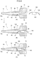
FIG.1 is a schematic view showing the whole structure of an intraocular lens insertion device according to a first embodiment of the invention. -
FIG.2 is a schematic view showing the front and side views of a cartridge. -
FIG.3 is a perspective view showing the whole structure of the cartridge and a casing. -
FIG.4 is a schematic view showing the cartridge being placed onto the casing. -
FIG.5 is a schematic view showing the front, side and back views of the casing. -
FIG.6 is a cross-sectional view of the cartridge used for explanation of how the intraocular lens is installed in the cartridge placed onto the casing. -
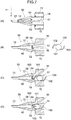
FIG.7 is a cross-sectional view of the cartridge used for explanation of how the intraocular lens is installed in the cartridge according to a second embodiment. -
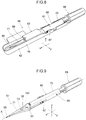
FIG.8 is a perspective view showing the whole structure of the intraocular lens insertion device with the casing according to a third embodiment. -
FIG.9 is a perspective view showing the structure of the intraocular lens insertion device according to the third embodiment. -
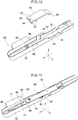
FIG. 10 is a perspective view showing the structures of the casing and a cover body. -
FIG.11 is a perspective view showing the intraocular lens insertion device placed onto the casing according to the third embodiment. -
FIG.12 is a schematic view showing the front and side views of the intraocular lens. -
FIG.13 is a schematic view illustrating how the intraocular lens is inserted into the eye using the intraocular lens insertion device. - Preferred embodiments of the present invention are described hereinafter with reference to the drawings.
- In
FIG.1 ,reference numeral 1 indicates an intraocular lens insertion device as a whole. The intraocularlens insertion device 1 comprises acartridge 2 and aninsertion device body 3 having aplunger 4. Thecartridge 2 is attached to an attachingportion 3a of theinsertion device body 3. Further, the intraocularlens insertion device 1 has anintraocular lens 100 installed in thecartridge 2, and is structured so as to be able to discharge theintraocular lens 100 from the tip end of thecartridge 2 into an eye by pushing out theintraocular lens 100 in the lens-advancing direction x (i.e., the direction of an arrow x, or an anterior direction in the lens-advancing axis A) using theplunger 4. - The
cartridge 2 attached to theinsertion device body 3 as referred to above is described further below. As shown inFIG.2 (A) , thecartridge 2, serving as a cylindrical or tubular insertion portion, comprises acartridge body 14 composed of a lens insertion opening 10, alens placement portion 11, atransition portion 12 and anozzle 13 in sequence, along the lens-advancing axis A; andwings cartridge body 14 along the lateral direction y perpendicular to the lens-advancing direction x. - The
lens insertion opening 10 is provided with aninsertion groove 16 formed on upper and lower surfaces by being cut out in the lens-advancing direction x. Thelens placement portion 11 is provided anterior to the lens insertion opening 10 with respect to the lens-advancing axis A, and thetransition portion 12 is provided anterior to thelens placement portion 11 with respect to the lens-advancing axis A. An inner wall of thetransition portion 12 is formed in the shape of a mortar gradually tapering toward the tip end thereof, and the tip end of thetransition portion 12 is communicated with thenozzle 13. - In this way, the
cartridge body 14 is formed such that theintraocular lens 100 can be moved from thelens placement portion 11 through thetransition portion 12 to thenozzle 13 in sequence by being pushed with theplunger 4 in the lens-advancing direction x. Also, thecartridge body 14 is formed so as to be able to discharge the intraocular lens pushed by theplunger 4 into the eye from adischarge port 13a of thenozzle 13. Here, thenozzle 13 is contoured so that it can be inserted into an incision (not shown). - In addition to the above-mentioned basic structure, the
cartridge 2 of the present invention is provided with aprotrusion insertion hole 20 formed so as to penetrate the thickness thereof in the vicinity of thelens placement portion 11 toward the vertical direction z perpendicular to both the lens-advancing direction x and the lateral direction y, as illustrated inFIGs. 2(A) and 2(B) . In the case of the present embodiment, theprotrusion insertion hole 20 is, as shown inFIG.2(A) , shifted toward one side relative to the lens-advancing axis A (in this case, downward) and is formed so as to allow a hole region thereof to cross only a part of a transition space in which theintraocular lens 100 moves. - Furthermore, the
cartridge 2 is formed so as to be detachable from acasing 22 on which aprotrusion 21 is vertically provided so that theprotrusion 21 may be inserted into theprotrusion insertion hole 20 by attaching thecartridge 2 to the casing. When thecartridge 2 is attached to thecasing 22 and thus theprotrusion 21 is inserted into theprotrusion insertion hole 20, theprotrusion 21 is allowed to pass through a part of the transition space in thecartridge 2 so that the tip end of theprotrusion 21 is exposed to the outside. - Here, as shown in
FIGs.5(A), 5(B) and 5(C) , thecasing 22 includes a casingmain body 23 to which thecartridge 2 is attached, and the casingmain body 23 is provided withfixing claws cartridge 2 to the casingmain body 23 and the saidprotrusion 21 that is to be inserted into theprotrusion insertion hole 20 at the time of the attachment of thecartridge 2. - The casing
main body 23 is integrally formed of a synthetic resin material such as a plastic material, and comprises a tip-side holding portion 25 holding thetransition portion 12 andnozzle 13 of thecartridge 2; and an insertion-side holding portion 26 holding the lens insertion opening 10,lens placement portion 11 andwings cartridge 2. - According to the present embodiment, the tip-
side holding portion 25 includes abase plate 27 having a bell shape as a whole such that its side faces are slightly concavely curved toward the inside at their central portions, and awall portion 28 vertically provided along the outer fringe of thebase plate 27. Thus, the tip-side holding portion 25 is formed such that the side faces of thewall portion 28 are also slightly concavely curved toward the inside at their central portions, corresponding to the contour of thebase plate 27, so that it may be easily held between user's thumb and index finger. - The tip-
side holding portion 25 includes acutout portion 30 provided at awall portion 29 on a proximal portion thereof adjacent to the insertion-side holding portion 26. Thecutout portion 30 is formed by being cut out in a concavely curved manner, corresponding to the contour of thetransition portion 12 of thecartridge 2, thereby enabling thetransition portion 12 of thecartridge 2 to be placed on thecutout portion 30. - Further, the tip-
side holding portion 25 includes aninner wall portion 31 spaced a distance away from thewall portion 29 on the proximal portion, extending toward the lateral direction y. Theinner wall portion 31 is cut out in a concavely curved manner, corresponding to the contour of thetransition portion 12 of thecartridge 2, thereby enabling thetransition portion 12 of thecartridge 2 to be placed on acutout portion 32 thereof as well. - Furthermore, the tip-
side holding portion 25 includes the two fixingclaws base plate 27 between thewall portion 29 on the proximal side and theinner wall portion 31. Here, the two fixingclaws claws cartridge 2 is placed on thecasing 22 and returning the fixingclaws - The fixing
claws claw 24a folded back toward the upper face side of thecartridge 2, so that thecartridge 2 may be fitted and held in thecasing 22 through the two fixingclaws side holding portion 25. - On the other hand, the insertion-
side holding portion 26 comprises abase plate 35 formed by cutting a rectangular plate in a letter U shape, and awall portion 36 vertically provided at both side faces of thebase plate 35. The insertion-side holding portion 26 is configured to hold thecartridge 2 due to thewings 15 of thecartridge 2 abutting onto the upper faces of thewall portions 36 when thecartridge 2 is fitted in the fixingclaws 24 of the tip-side holding portion 25 (SeeFIG.4 ). - In addition to the above-mentioned structure, the
casing 22 of the present invention is provided with theprotrusion 21 vertically extending from thebase plate 35 of the insertion-side holding portion 26. Theprotrusion 21 is formed so that it may be able to be inserted into theprotrusion insertion hole 20 of thecartridge 2 when thecartridge 2 is installed in thecasing 22 through the fixingclaws side holding portion 25. - In practice, the
protrusion 21, serving as a folding means, is strip-shaped and formed to have a given thickness, corresponding to the shape of the opening of theprotrusion insertion hole 20 of thecartridge 2, and is vertically provided on thebase plate 35 of the insertion-side holding portion 26 so as to be extended in the vertical direction z. With thecartridge 2 being installed onsuch casing 22, theintraocular lens 100 can be inserted from thelens insertion opening 10 of thecartridge 2. - Then, as shown in
FIG. 6(A) , theoptical portion 101 of theintraocular lens 100 is folded in two with supportingportions optical portion 101 is grasped with tweezers (not shown), and then, as shown inFIG.6(B) , the intraocular lens is inserted into thelens insertion opening 10 while it is arranged so as to allow the tip end of one of the supportingportions 102 to abut onto theprotrusion 21. Here, for sake of simplicity, the casingmain body 23 is not shown but only theprotrusion 21 is shown inFIG.6 . - Then, the
cartridge 2 allows the distal end of the supportingportion 102 of theintraocular lens 100 to abut onto theprotrusion 21 that is exposed within thetransition space 39. With the tip actually being abutted onto theprotrusion 21, theintraocular lens 100 is inserted up to thelens placement portion 11 by the tweezers. In this way, as shown inFIG.6(C) , thecartridge 2 allows the distal end of the supportingportion 102 to be folded back by theprotrusion 21 in the opposite direction against the lens-advancing direction x (hereinafter, this is called backward direction). - Thus, the
cartridge 2 is able to place theintraocular lens 100 on thelens placement portion 11 with the supportingportion 102 being folded in a substantially U-shape by theprotrusion 21. - Moreover, the
cartridge 2 is formed such that theoptical portion 101 of theintraocular lens 100 abuts on theprotrusion 21 that is inserted through theprotrusion insertion hole 20 and is exposed to thetransition space 39, so that theprotrusion 21 receives theoptical portion 101, thereby precisely positioning theintraocular lens 100 on thelens placement portion 11. - After that, the
cartridge 2 is removed from thecasing 22 and thus theprotrusion 21 is allowed to disengage from theprotrusion insertion hole 20. However, thecartridge 2 can keep the distal end of the supportingportion 102 folded back toward theoptical portion 101 by allowing the supportingportion 10 of theintraocular lens 100, which had been abutted onto theprotrusion 21 until then, to abut onto aninner wall 40 of thetransition space 39. In such state, thecartridge 2 is capable of being attached to the attachingportion 3a of theinsertion device body 3. Thus, the intraocularlens insertion device 1 allows theintraocular lens 100 to be pushed out by theplunger 4 toward the lens-advancing direction x with the supportingportion 102 being folded back, thus enabling theintraocular lens 100 to be released into an eye from thenozzle 13 provided on the tip end of thecartridge 2. - At this time, the intraocular
lens insertion device 1 of the present invention allows the curved portion of the folded supportingportion 102, which has become U-shaped and less likely to move freely, to be exposed from thedischarge port 13a of thenozzle 13, and then allows theoptical portion 101 to be released from thedischarge port 13a thereof by pushing out theintraocular lens 100 by theplunger 4, thereby preventing only the distal end of the supportingportion 102 from being released and moved freely in the process of releasing theintraocular lens 100 into the eye from the tip end of thecartridge 2. - According to the above-mentioned structure, the
cartridge 2 is installed in thecasing 22, thereby allowing theprotrusion 21 provided on thecasing 22 to be inserted into theprotrusion insertion hole 20 so that theprotrusion 21 can be exposed to thetransition space 39. - A user may insert the
intraocular lens 100 from thelens insertion opening 10 with thecartridge 2 being installed in thecasing 22, and place theintraocular lens 100 on thelens placement portion 11. At this time, the user can pinch thewall portion 28 of thecasing 22 much larger in size than thewings wings cartridge 2, thereby enabling thecartridge 2 to be easily stabilized. Thus, the user can place theintraocular lens 100 on thelens placement portion 11 more easily than by the conventional ones. - Further, the user can hold the
cartridge 2 in a stable condition by pinching thewall portion 28 of thecasing 22, thus enabling the user to easily fill a viscoelastic material such as a hyaluronic acid preparation for ophthalmic application into the inside of thecartridge 2. - Furthermore, according to the
cartridge 2, when theintraocular lens 100 is gradually inserted from thelens insertion opening 10 in order to place theintraocular lens 100 on thelens placement portion 11, the distal end of the supportingportion 102 of theintraocular lens 100 is allowed to abut on theprotrusion 21, and thus the distal end of the supportingportion 102 in the lens-advancing direction x can be folded backward. - Particularly, according to the present embodiment, since the
protrusion 21 is not exposed all through thetransition space 39, but is only exposed in a part thereof at one side in the lens-advancing axis A, it is possible to allow only the distal end of the supportingportion 102 to abut on theprotrusion 21, thereby ensuring an intermediate portion between the distal end of the supportingportion 102 and the proximal portion thereof to be folded in a U-shape. - According to the intraocular
lens insertion device 1, therefore, the supportingportion 102 of the intraocular lens placed on the lens advancing side with respect to the lens-advancing direction x is pressed against theprotrusion 21 to thereby be folded backward, thus enabling the curved portion of the folded supportingportion 102, which has become U-shaped and less likely to move freely, to be first released when releasing theintraocular lens 100 from thenozzle 13. Thus, theintraocular lens 100 can be more easily inserted into an eye with the same kept in a more stable condition than by the conventional ones. - Moreover, the intraocular
lens insertion device 1 is detachably provided with theprotrusion 21, thereby preventing theprotrusion 21 from blocking the movement of theintraocular lens 100 when inserting theintraocular lens 100 into an eye. - Additionally, according to the present embodiment, the
protrusion insertion hole 20 of thecartridge 2 is drilled at the top face of thelens placement portion 11 so that the tip of theprotrusion 21 of thecasing 22 is exposed from the top face of thelens placement portion 11, and thus a user can visually confirm the position of theprotrusion 21 in a moment. Accordingly, it is possible to ensure the distal end of the supportingportion 102 to be properly placed on the side of theprotrusion 21 so that the supportingportion 102 may be pressed to theprotrusion 21 and folded when theintraocular lens 100 is placed on thelens placement portion 11. - Also, according to the present embodiment, the
protrusion 21 is provided on thecasing 22, and thus even thin andshort protrusion 21 can be inserted into and removed from theprotrusion insertion hole 20 of thecartridge 2 by just attaching and detaching thecasing 22 to and from thecartridge 2. - Besides, the
cartridge 2 is installed in thecasing 22, and thus thenozzle 13, thetransition portion 12 and the like can be protected against an external force owing to thecasing 22. In addition, thecartridge 2 can be placed on a pedestal with thecasing 22 installed, thus preventing thenozzle 13, thetransition portion 12 and the like from directly contacting the pedestal. Accordingly, thecartridge 2 can be always kept clean. -
FIG.7 which is given the same reference numerals as corresponding parts inFIG. 6 shows a cartridge according to a second embodiment. Acartridge 50 is different from that of the foregoing first embodiment in that theoptical portion 101 is inserted into alens insertion opening 51 without being folded in half. - In practice, as shown in
FIG.7(A) and 7(B) , thecartridge 50 is formed so as to be able to be installed in the casing not shown in the drawings. When it is installed in the casing, aprotrusion 52 provided on the casing is allowed to be inserted into aprotrusion insertion hole 53. In the meantime, for sake of simplicity, the casing is not shown inFIG.7 but only theprotrusion 52 is shown therein. - In practice, the
protrusion insertion hole 53 is drilled so as to penetrate the thickness in the vicinity of thelens placement portion 54 toward the bottom-to-top direction (toward a viewer seeing the drawing) perpendicular to both the lens-advancing direction x and the lateral direction y. In this embodiment, theprotrusion insertion hole 20 is drilled in the substantial center of thelens placement portion 54 so as to cross the lens-advancing axis A, and thus an hole region is formed in the middle of the transition space in which theintraocular lens 100 moves. - Thus, when the
protrusion 52 is inserted intoprotrusion insertion hole 53 by installing thecartridge 50 in the casing, theprotrusion 52 passes through the middle of thetransition space 39 and the tip of theprotrusion 52 can be exposed to the outside. - In that state, the
intraocular lens 100 is pinched with a tweezers (not shown) with the supportingportions optical portion 101 unfolded, and then it may be inserted into thelens insertion opening 51 of thecartridge 50, with the tip of one supportingportion 102 being the leading end, as illustrated inFIG.7(C) . - At this time, the
cartridge 50 allows the distal end of the supportingportion 102 of theintraocular lens 100 to abut on theprotrusion 21 exposed inside thetransition space 39. In that state, theintraocular lens 100 is inserted up to thelens placement portion 54 by the tweezers. In this way, as shown in FIG. 6(D), thecartridge 50 allows the distal end of the supportingportion 102 to be folded back along a curved surface of theprotrusion 52 in the opposite direction relative to the lens-advancing direction x. Thus, thecartridge 50 enables theintraocular lens 100 to be placed on thelens placement portion 54 with the supportingportion 102 being folded in a U-shape by theprotrusion 52. - In this embodiment, the surface of the
protrusion 52 on which the supportingportion 102 of theintraocular lens 100 abuts is curved toward a given direction, thereby ensuring the supportingportion 102 of theintraocular lens 100 to be bent in a desired direction along the curved surface. - After that, like in the above-mentioned first embodiment, the
cartridge 50 is removed from the casing and thus theprotrusion 52 disengages from theprotrusion insertion hole 53. Thecartridge 50, however, is capable of keeping the distal end of the supportingportion 102 folded due to the supportingportion 102 of theintraocular lens 100, which had been abutted on theprotrusion 52 until then, to then abut onto theinner wall 40 in thetransition space 39. In such state, thecartridge 50 is capable of being attached to the attaching portion of the insertion device body not shown. Thus, the intraocular lens insertion device allows theintraocular lens 100 to be pushed out by theplunger 4 in the lens-advancing direction x with the supportingportion 102 being folded back, thus enabling theintraocular lens 100 to be released into an eye from thenozzle 13 provided on the tip end of thecartridge 2. - In
FIG.8 , numeral 60 denotes an assembly of an intraocular lens insertion device and a casing according to a third embodiment. Theassembly 60 of an intraocular lens insertion device and a casing comprises an intraocularlens insertion device 61, acasing 62 on which the intraocularlens insertion device 61 is detachably installed, and acover body 63 which is detachably attached to thecasing 62 on which the intraocularlens insertion device 61 is installed to cover the intraocularlens insertion device 61. - At first, the intraocular
lens insertion device 61 is described hereinbelow. The intraocularlens insertion device 61 is of a preset-type in which theintraocular lens 100 is set in advance, unlike in the foregoing first and second embodiments. - As shown in
FIG.9 , the intraocularlens insertion device 61 comprises amain body 66, aslider 67, aplunger 68 and a locking mechanism, and thismain body 66 comprises a cylindricalproximal member 70 and a tapereddistal member 71. - In this case, a lens placement portion (not shown) made of a plate member is provided in the distal portion of the
proximal member 70 on the lens advancing side with respect to the lens-advancing axis A so that theintraocular lens 100 may be placed on the lens placement portion. Further, the tapereddistal member 71 is connected integrally with theproximal member 70 so that theintraocular lens 100 placed on the lens placement portion of theproximal member 70 may be placed in the inside of the tapereddistal member 71. - The
slider 67 and theplunger 68 are provided so as to be movable back-and-forth in themain body 66. Thelocking mechanism 69 can limit the forward movement of theplunger 68. Thelocking mechanism 69 is unlocked by moving theslider 67 forward, thereby allowing theplunger 68 to be movable forward. - The intraocular
lens insertion device 61 thus structured allows theintraocular lens 100 to be pushed by theslider 67 so that it is properly folded in a predetermined shape at first, and then allows theintraocular lens 100 to be inserted into an eye by folding theintraocular lens 100 even smaller by continuously pushing theintraocular lens 100 by theplunger 68. Accordingly, the intraocularlens insertion device 61 is structured such that thelocking mechanism 69 thereof ensures that theintraocular lens 100 is prevented from being pushed out by theplunger 68 prior to being pushed out by theslider 67, and thus theintraocular lens 100 placed in themain body 66 is folded as it is moved forward in two steps by theslider 67 and then by the plunger. - These matters have already been disclosed by the present applicant. For details relating to the matters, one may refer to the description in Best Mode for Carrying Out the Invention in
PCT/JP2008/59995 - In this case, the cylindrical insertion portion according to
claim 1 comprises the lens placement portion and the tapereddistal member 71, and in the tapereddistal member 71, aprotrusion insertion hole 73 is drilled so as to penetrate the thickness of the tapereddistal member 71 toward the vertical direction z perpendicular to both the lens-advancing direction x and the lateral direction y. According to this embodiment, theprotrusion insertion hole 73 is drilled in the approximate center of thelens placement portion 54 so as to cross the lens-advancing axis A, and a hole region is formed in the middle of the transition space in which theintraocular lens 100 moves. - The intraocular
lens insertion device 61 is capable of being removably attached to thecasing 62 which is separate from the intraocularlens insertion device 61 and is formed from e.g., a synthetic resin material into a one-piece structure. As shown inFIG.10 , aU-shaped wall portion 76 is vertically provided on abase plate 75 of thecasing 63, in a manner surrounding the intraocularlens insertion device 61, while aprotrusion 80 is vertically provided on a given position of thebase plate 75. - The
protrusion 80 has the same structure as that of the foregoing second embodiment so that it may be, as shown inFIG.11 , inserted into theprotrusion insertion hole 73 of the intraocularlens insertion device 61 by installing the intraocularlens insertion device 61 in thecasing 62. In this way, in the intraocularlens insertion device 61, theprotrusion 80 of thecasing 62 can be arranged in the center region of the transition space of the tapereddistal member 71. - Also, as shown in
FIG.10 , thewall portion 76 of thecasing 62 is formed, on its both sides, with a steppedportion 81 whose height from thebase plate 75 is comparatively low. As shown inFIG.11 , when the intraocularlens insertion device 61 is installed, theslider 67 of the intraocularlens insertion device 61 is capable of being located on the steppedportion 81. At this time, there is a given distance between an abuttingsurface 82 of thewall portion 76 and theslider 67 of the intraocularlens insertion device 61. - Thus, the intraocular
lens insertion device 61 can move theintraocular lens 100 installed inside the tapereddistal member 71 toward the lens-advancing direction x up to a given position, by allowing theslider 67 in the lens-advancing direction x until it abuts on the abuttingsurface 82 of thewall portion 76 of thecasing 62. - In this way, like in the foregoing second embodiment, the
intraocular lens 100 is allowed to have its supportingportion 102 abutted on theprotrusion 80 so as to have the tip end of the supportingportion 102 folded back along a curved surface of theprotrusion 80 in the backward direction opposed to the lens-advancing direction x. Thus, the intraocularlens insertion device 61 is capable of placing theintraocular lens 100 on the lens placement portion (not shown) with the supportingportion 102 folded in a substantially U- shape by theprotrusion 80. - Also, the intraocular
lens insertion device 61 is detached from thecasing 62 with the above arrangement being retained, and then theintraocular lens 100 is pushed out by theplunger 68 in the lens-advancing direction x with the supportingportion 102 folded back, thereby allowing theintraocular lens 100 to be released from anozzle 85 of the tapereddistal member 71. - In the meantime, as shown in
FIG.10 ,fitting holes 86 are drilled on the top surface of thewall portion 76 of thecasing 62 so thatfitting protrusions 87 provided on the lower surface of thecover body 63 may be fitted into the fitting holes 86, thereby allowing thecover body 63 to be attached to thecasing 62. - In practice, the contour of the lower surface of the
cover body 63 is formed corresponding to that of the top surface of thewall portion 76 of thecasing 62, and thus it includes a stepped abuttingportion 88 formed corresponding to the shape of the steppedportion 81 of thewall portion 76. - Accordingly, as shown in
FIG.8 , when thecover body 63 is attached to thecasing 62 on which the intraocularlens insertion device 61 is installed, the stepped abuttingportion 88 is fitted in a gap formed between the abuttingsurface 82 of thewall portion 76 of thecasing 62 and theslider 67 of the intraocularlens insertion device 61, thereby preventing theslider 67 from sliding. - Additionally, as shown in
FIG.10 , thecover body 63 may have, for example, two positioningprotrusions positioning protrusions distal member 71 of the intraocular lens insertion device 61 (seeFIG.9 ). Accordingly, when thecover body 63 is attached to thecasing 62, the positioningprotrusions cover body 63 are inserted into these positioning holes 92, 93 respectively, thereby allowing the two supportingportions intraocular lens 100 to be properly positioned by allowing them to abut on thepositioning protrusions lens insertion device 61 allows a viscoelastic material such as a hyaluronic acid preparation for ophthalmic application to be filled thereinside through onepositioning hole 91 by a syringe or the like not shown in the drawings. - From the above-mentioned structure, the intraocular
lens insertion device 61 enables the supportingportion 102 of theintraocular lens 100 arranged on the lens-advancing side with respect to the lens-advancing direction x to be bent by theprotrusion 80 in the backward direction, thus enabling the curved portion of the supportingportion 102, which has become U-shaped and hardly movable, to be released first when releasing theintraocular lens 100 from the tapereddistal member 71, thereby enabling theintraocular lens 100 to be inserted into an eye more easily and stably compared to by the conventional ones. - The present invention is not limited to the foregoing embodiments and various modifications are possible within the scope of the gist of the present invention. For example, the protrusion may be formed in a circular or various other shapes. Further, the present invention is also applicable to other intraocular lens which has only one supporting portion, or three, four or more supporting portions provided on the optical portion.
- Whilst the supporting
portion 102 is folded in a U-shape by theprotrusions portion 102 may be folded in V-, C-, L- or various other shapes by theprotrusions - Moreover, whilst the
protrusions portion 102 of theintraocular lens 100 can be folded in the backward direction which is opposed to the lens-advancing direction x. In these cases, a protrusion insertion hole may be drilled in thecartridge distal member 71, corresponding to the extending direction of the protrusion. - Additionally, whilst the
protrusions casings - In addition, whilst the
protrusion insertion hole 20 is provided in the vicinity of thelens placement portion 11 in the foregoing embodiments, the present invention is not limited to this. Theprotrusion 21 may be provided on thelens insertion opening 10,transition portion 12, or various other portions, as long as the tip end of the supportingportion 102 of theintraocular lens 100 can be folded in the backward direction as opposed to the lens-advancing direction x when the intraocular lens is released from thenozzle 13. - In addition to the foregoing, whilst the
protrusion insertion hole 20 is drilled through between the top surface and the lower surface of thelens placement portion 11 and the tip of theprotrusion 21 is exposed from the top surface of thelens placement portion 11 in the foregoing embodiments, the present invention is not limited thereto. Theprotrusion insertion hole 20 may be drilled through only the lower surface of thelens placement portion 11 so that the tip of theprotrusion 21 may not be exposed from the top surface of thelens placement portion 11.
Claims (3)
- An assembly for use with an intraocular lens (100) having an optical portion (101) with an outer fringe and first and second supporting portions (102) on the outer fringe, the assembly comprising:an intraocular lens insertion device (61) including a tapered distal member (71) with an internal lumen and a nozzle portion (85), a lens placement portion for storing the intraocular lens (100) in such a manner that the first supporting portion (102) is located between the optical portion (101) and the nozzle portion (85), and a plunger (68) that pushes the intraocular lens in a lens advancing direction (x) through the nozzle portion (85); anda casing (62) on which the intraocular lens insertion device (61) is detachably installed;characterized bythe tapered distal member (71) of the intraocular lens insertion device (61) includes a protrusion insertion hole (73);the casing (62) includes a protrusion (80); andthe intraocular lens insertion device (61) and the casing (62) are respectively configured such that the protrusion (80) extends through the protrusion insertion hole (73) and into the internal lumen at a location between the nozzle portion (85) and the first support portion (102) when the intraocular lens insertion device (61) is installed on the casing (62).
- The assembly according to claim 1, wherein the protrusion (80) is configured to bend the first supporting portion (102) backward when the intraocular lens (100) moves in the lens advancement direction (x) and the intraocular lens insertion device (61) is installed on the casing (62).
- The assembly according to claim 1 or claim 2, wherein the intraocular lens (100) is preloaded within the intraocular lens insertion device (61).
Priority Applications (1)
| Application Number | Priority Date | Filing Date | Title |
|---|---|---|---|
| EP20165537.0A EP3708118B1 (en) | 2008-06-05 | 2009-06-03 | Intraocular lens insertion device and cartridge |
Applications Claiming Priority (2)
| Application Number | Priority Date | Filing Date | Title |
|---|---|---|---|
| JP2008147781A JP5254669B2 (en) | 2008-06-05 | 2008-06-05 | Intraocular lens insertion device and cartridge |
| PCT/JP2009/060184 WO2009148091A1 (en) | 2008-06-05 | 2009-06-03 | Intraocular lens inserting instrument and cartridge |
Related Child Applications (1)
| Application Number | Title | Priority Date | Filing Date |
|---|---|---|---|
| EP20165537.0A Division EP3708118B1 (en) | 2008-06-05 | 2009-06-03 | Intraocular lens insertion device and cartridge |
Publications (3)
| Publication Number | Publication Date |
|---|---|
| EP2298242A1 EP2298242A1 (en) | 2011-03-23 |
| EP2298242A4 EP2298242A4 (en) | 2017-06-21 |
| EP2298242B1 true EP2298242B1 (en) | 2020-04-01 |
Family
ID=41398164
Family Applications (2)
| Application Number | Title | Priority Date | Filing Date |
|---|---|---|---|
| EP20165537.0A Active EP3708118B1 (en) | 2008-06-05 | 2009-06-03 | Intraocular lens insertion device and cartridge |
| EP09758358.7A Active EP2298242B1 (en) | 2008-06-05 | 2009-06-03 | Assembly for use with a intraocular lens |
Family Applications Before (1)
| Application Number | Title | Priority Date | Filing Date |
|---|---|---|---|
| EP20165537.0A Active EP3708118B1 (en) | 2008-06-05 | 2009-06-03 | Intraocular lens insertion device and cartridge |
Country Status (5)
| Country | Link |
|---|---|
| US (2) | US9554894B2 (en) |
| EP (2) | EP3708118B1 (en) |
| JP (1) | JP5254669B2 (en) |
| CN (1) | CN102056571B (en) |
| WO (1) | WO2009148091A1 (en) |
Families Citing this family (48)
| Publication number | Priority date | Publication date | Assignee | Title |
|---|---|---|---|---|
| US8460311B2 (en) | 2004-12-27 | 2013-06-11 | Hoya Corporation | Intraocular lens implanting device |
| EP1849436B1 (en) | 2005-01-26 | 2017-11-01 | Hoya Corporation | Intraocular lens insertion device |
| JP4836046B2 (en) | 2005-02-24 | 2011-12-14 | Hoya株式会社 | Intraocular lens insertion device |
| EP1941846B1 (en) | 2005-09-28 | 2021-01-27 | Hoya Corporation | Intraocular lens insertion device |
| JP4877643B2 (en) * | 2005-12-08 | 2012-02-15 | Hoya株式会社 | Intraocular lens insertion device |
| JP5236638B2 (en) | 2007-05-30 | 2013-07-17 | Hoya株式会社 | Intraocular lens insertion device |
| CN101677853B (en) | 2007-05-30 | 2012-04-18 | Hoya株式会社 | Intraocular lens inserting tool |
| JP5086713B2 (en) | 2007-07-11 | 2012-11-28 | Hoya株式会社 | Intraocular lens insertion device |
| US8968396B2 (en) | 2007-07-23 | 2015-03-03 | Powervision, Inc. | Intraocular lens delivery systems and methods of use |
| JP5254669B2 (en) | 2008-06-05 | 2013-08-07 | Hoya株式会社 | Intraocular lens insertion device and cartridge |
| JP5470753B2 (en) | 2008-06-17 | 2014-04-16 | Hoya株式会社 | Intraocular lens insertion device |
| JP5323420B2 (en) | 2008-08-21 | 2013-10-23 | Hoya株式会社 | Intraocular lens insertion device |
| JP5416379B2 (en) | 2008-09-04 | 2014-02-12 | Hoya株式会社 | Intraocular lens insertion device |
| WO2010079780A1 (en) | 2009-01-07 | 2010-07-15 | Hoya株式会社 | Intraocular lens insertion device |
| ES2549727T3 (en) * | 2009-10-22 | 2015-11-02 | Kowa Company Ltd. | Intraocular lens insertion device |
| US9326847B2 (en) | 2010-04-08 | 2016-05-03 | Hoya Corporation | Ocular implant insertion apparatus and methods |
| JP5511530B2 (en) | 2010-06-10 | 2014-06-04 | Hoya株式会社 | Intraocular lens insertion device |
| WO2012006616A2 (en) | 2010-07-09 | 2012-01-12 | Powervision, Inc. | Intraocular lens delivery devices and methods of use |
| JP2014505521A (en) * | 2010-12-20 | 2014-03-06 | ノバルティス アーゲー | Intraocular lens transfer case |
| ES2725562T3 (en) | 2011-09-15 | 2019-09-24 | Kowa Co | Intraocular lens insertion tool |
| US8690941B2 (en) * | 2011-10-04 | 2014-04-08 | Novartis Ag | Intraocular lens surgical system and method |
| JP5874351B2 (en) * | 2011-11-29 | 2016-03-02 | 株式会社ニデック | Intraocular lens insertion system |
| EP2797555A1 (en) * | 2011-12-30 | 2014-11-05 | Haydaroglu, Orhan | Intraocular lens cartridge |
| ES2610198T3 (en) | 2012-06-04 | 2017-04-26 | Alcon Pharmaceuticals Ltd. | Intraocular lens insertion device and method for unloading an intraocular lens from a cartridge |
| EP2858593B1 (en) | 2012-06-12 | 2020-09-30 | Alcon Inc. | Intraocular gas injector |
| US9155615B2 (en) * | 2012-11-09 | 2015-10-13 | Bausch & Lomb Incorporated | Hingeless cartridge for use with an intraocular lens injector providing haptic control |
| US9237947B2 (en) * | 2012-11-09 | 2016-01-19 | Bausch & Lomb Incorporated | Hingeless cartridge for intraocular lens injector providing haptic control |
| EP3785668A1 (en) | 2013-03-15 | 2021-03-03 | Alcon Inc. | Intraocular lens storage and loading devices and methods of use |
| JPWO2015012312A1 (en) * | 2013-07-24 | 2017-03-02 | 興和株式会社 | Intraocular lens insertion device |
| CN104414774B (en) * | 2013-08-28 | 2017-12-22 | 爱博诺德(北京)医疗科技有限公司 | Prepackage type intraocular lens injector |
| JP5694489B2 (en) * | 2013-11-25 | 2015-04-01 | 興和株式会社 | Intraocular lens insertion device |
| JP6276619B2 (en) | 2014-03-19 | 2018-02-07 | Hoya株式会社 | Intraocular lens insertion device and intraocular lens insertion device |
| EP3125840B1 (en) | 2014-04-04 | 2021-03-24 | Alcon Inc. | Intraocular lens inserter |
| US10588780B2 (en) | 2015-03-04 | 2020-03-17 | Alcon Inc. | Intraocular lens injector |
| JP6646987B2 (en) | 2015-09-16 | 2020-02-14 | Hoya株式会社 | Intraocular lens insertion device |
| CN107920891A (en) | 2015-09-16 | 2018-04-17 | Hoya株式会社 | Intraocular lens inserting instrument |
| US10172706B2 (en) | 2015-10-31 | 2019-01-08 | Novartis Ag | Intraocular lens inserter |
| US11547555B2 (en) | 2015-12-17 | 2023-01-10 | Atrion Medical Products, Inc. | Intraocular lens delivery device and method of use |
| US10722347B2 (en) | 2015-12-17 | 2020-07-28 | Atrion Medical Products, Inc. | Intraocular lens delivery device and method of use |
| JP6929843B2 (en) | 2016-06-28 | 2021-09-01 | Hoya株式会社 | Intraocular lens inserter |
| US11000367B2 (en) | 2017-01-13 | 2021-05-11 | Alcon Inc. | Intraocular lens injector |
| US10568735B2 (en) | 2017-01-13 | 2020-02-25 | Alcon Inc. | Intraocular lens injector |
| US10426602B2 (en) * | 2017-10-05 | 2019-10-01 | Ast Products, Inc. | Intraocular lens (IOL) injector and method of use thereof |
| US10925722B2 (en) * | 2018-04-26 | 2021-02-23 | Visioncare Inc. | Apparatus for use in implanting intraocular lenses and method of preparing apparatus for use |
| US10849739B2 (en) * | 2018-08-02 | 2020-12-01 | Carl Zeiss Meditec Ag | Ophthalmosurgical injector system |
| US11224537B2 (en) | 2018-10-19 | 2022-01-18 | Alcon Inc. | Intraocular gas injector |
| JP7327956B2 (en) * | 2019-03-13 | 2023-08-16 | Hoya株式会社 | Intraocular lens insertion device |
| JP7430128B2 (en) | 2020-09-09 | 2024-02-09 | Hoya株式会社 | Intraocular lens insertion device and its design method |
Citations (2)
| Publication number | Priority date | Publication date | Assignee | Title |
|---|---|---|---|---|
| EP1502559B1 (en) | 2003-07-31 | 2006-11-15 | Nidek Co., Ltd. | Intraocular lens injector |
| EP1808150A1 (en) | 2006-01-11 | 2007-07-18 | Nidek Co., Ltd | Intraocular lens injector and intraocular lens injecting system including the same |
Family Cites Families (248)
| Publication number | Priority date | Publication date | Assignee | Title |
|---|---|---|---|---|
| US1003966A (en) | 1910-12-31 | 1911-09-19 | H L Judd Company | Curtain-rod socket. |
| US2761446A (en) | 1955-03-30 | 1956-09-04 | Chemical Specialties Co Inc | Implanter and cartridge |
| GB999506A (en) | 1960-11-02 | 1965-07-28 | Engis Ltd | Improvements in syringes for dispensing paste or the like |
| US4066297A (en) * | 1976-06-01 | 1978-01-03 | Atlantic Richfield Company | Process for the recovery of uranium |
| US4205747A (en) | 1978-09-05 | 1980-06-03 | Cilco, Inc. | Lens storage device |
| US4269307A (en) * | 1979-08-09 | 1981-05-26 | Iolab Corporation | Intraocular lens storage assembly |
| US4423809A (en) * | 1982-02-05 | 1984-01-03 | Staar Surgical Company, Inc. | Packaging system for intraocular lens structures |
| US4573998A (en) | 1982-02-05 | 1986-03-04 | Staar Surgical Co. | Methods for implantation of deformable intraocular lenses |
| US4702244A (en) | 1982-02-05 | 1987-10-27 | Staar Surgical Company | Surgical device for implantation of a deformable intraocular lens |
| US4608049A (en) | 1982-06-28 | 1986-08-26 | Kelman Charles D | Intraocular lens and method of inserting an intraocular lens into an eye |
| US4634423A (en) * | 1984-04-30 | 1987-01-06 | Bailey Jr Paul F | Ophthalmological method and instrument for implantation of posterior chamber intraocular lens |
| US4787904A (en) | 1984-07-06 | 1988-11-29 | Severin Sanford L | Hydrophillic intraocular lens |
| US4699140A (en) | 1985-07-10 | 1987-10-13 | Iolab Corporation | Instrument for inserting an intraocular lens |
| US4681102A (en) | 1985-09-11 | 1987-07-21 | Bartell Michael T | Apparatus and method for insertion of an intra-ocular lens |
| US4715373A (en) | 1985-09-27 | 1987-12-29 | Mazzocco Thomas R | Devices for implantation of deformable intraocular lens structures |
| US4750498A (en) | 1986-02-21 | 1988-06-14 | Coopervision, Inc. | Method and tool for inserting an intraocular lens |
| DE3610925C2 (en) | 1986-03-24 | 1994-11-03 | Michael Ulrich Prof D Dardenne | Device for folding an implantable intraocular lens, in particular provided with two plastic haptic plates on the side, and for inserting the folded intraocular lens into the eye |
| US4697697A (en) | 1986-08-18 | 1987-10-06 | Coopervision, Inc. | Method and apparatus for packaging an intraocular lens |
| US4919130A (en) * | 1986-11-07 | 1990-04-24 | Nestle S.A. | Tool for inserting compressible intraocular lenses into the eye and method |
| JPS63197453A (en) | 1986-11-07 | 1988-08-16 | ザ・クーパー・カンパニー・インク | Instrument and method for inserting compressive intraocular lens |
| US4747404A (en) * | 1986-11-10 | 1988-05-31 | Kresge Eye Institute Of Wayne State University | Foldable intraocular lens inserter |
| US4763650A (en) | 1987-01-20 | 1988-08-16 | Hauser Stephen G | Instrument for inserting a deformable lens into the eye |
| US4810249A (en) * | 1987-03-12 | 1989-03-07 | Habley Medical Technology Corp. | Linear and Vernier-type syringe |
| US4994028A (en) * | 1987-03-18 | 1991-02-19 | Endocon, Inc. | Injector for inplanting multiple pellet medicaments |
| US4819631A (en) * | 1987-03-26 | 1989-04-11 | Poley Brooks J | Folded intraocular lens, method of implanting it, retainer, and apparatus for folding lens |
| US4988352A (en) * | 1987-03-26 | 1991-01-29 | Poley Brooks J | Method and apparatus for folding, freezing and implanting intraocular lens |
| US5176686A (en) * | 1987-03-26 | 1993-01-05 | Poley Brooks J | Apparatus for packaging, folding, rigidifying and inserting an intraocular lens |
| US4769034A (en) | 1987-03-26 | 1988-09-06 | Poley Brooks J | Folded intraocular lens, method of implanting folded intraocular lens |
| US4781719A (en) | 1987-07-28 | 1988-11-01 | Kelman Charles D | Method of inserting an intraocular lens into an eye |
| US4759359A (en) | 1987-08-31 | 1988-07-26 | Allergan, Inc. | Lens implantation instrument |
| US4834094A (en) * | 1987-10-07 | 1989-05-30 | Patton Medical Technologies, Inc. | "Canoe" apparatus for inserting intra-ocular lens into the eye |
| US4765329A (en) | 1987-10-19 | 1988-08-23 | Cumming, Redwitz & Wilson, Inc. | Intraocular lens insertion instrument |
| US4934363A (en) | 1987-12-15 | 1990-06-19 | Iolab Corporation | Lens insertion instrument |
| US4880000A (en) | 1987-12-15 | 1989-11-14 | Iolab Corporation | Lens insertion instrument |
| US4836201A (en) | 1988-03-24 | 1989-06-06 | Patton Medical Technologies, Inc. | "Envelope" apparatus for inserting intra-ocular lens into the eye |
| US4862885A (en) | 1988-05-25 | 1989-09-05 | Cumming J Stuart | Instrument for inserting a deformable intraocular lens into the eye |
| CA2000287A1 (en) | 1988-10-07 | 1990-04-07 | David C. Buboltz | Intraocular lens insertion instrument |
| US5066297A (en) | 1989-01-23 | 1991-11-19 | Cumming J Stuart | Intraocular lens insertion device |
| US4976716A (en) | 1989-01-23 | 1990-12-11 | Cumming J Stuart | Intraocular lens insertion device |
| US4955889A (en) | 1989-02-06 | 1990-09-11 | Allergan, Inc. | Apparatus for inserting a lens into an eye and method for using same |
| US5098439A (en) * | 1989-04-12 | 1992-03-24 | Allergan, Inc. | Small incision intraocular lens insertion apparatus |
| US5222972A (en) | 1989-04-12 | 1993-06-29 | Allergan, Inc. | Small incision intraocular lens insertion apparatus |
| US5171241A (en) | 1989-06-09 | 1992-12-15 | Ioptex Research Inc. | Device for folding an intraocular lens and holding it in the folded state |
| DE4030492C1 (en) | 1990-09-26 | 1991-09-05 | Adatomed Pharmazeutische Und Medizintechnische Gesellschaft Mbh, 8000 Muenchen, De | |
| DE4039119C1 (en) | 1990-12-07 | 1991-09-05 | Dieter Dr.Med. 8904 Friedberg De Klaas | |
| DE4108303C2 (en) * | 1991-03-14 | 1993-11-04 | Adatomed Pharma & Med | METHOD AND DEVICE FOR INSERTING A RUBBER-ELASTIC INTRAOCULAR LENS IN AN IMPLANTATION TOOL |
| DE4110278A1 (en) | 1991-03-28 | 1992-10-01 | Geuder Hans Gmbh | Surgical instrument for implanting soft lenses in eye - has guide sleeve attached to handle by quick-action coupling |
| US5123905A (en) | 1991-06-07 | 1992-06-23 | Kelman Charles D | Intraocular lens injector |
| JPH0779825B2 (en) | 1991-06-13 | 1995-08-30 | キヤノンスター株式会社 | Intraocular lens implanter |
| JPH0779826B2 (en) | 1991-06-14 | 1995-08-30 | キヤノンスター株式会社 | Intraocular lens implanter |
| US5259395A (en) | 1992-01-15 | 1993-11-09 | Siemens Pacesetter, Inc. | Pacemaker lead with extendable retractable lockable fixing helix |
| US5190552A (en) * | 1992-02-04 | 1993-03-02 | Kelman Charles D | Slotted tube injector for an intraocular lens |
| US5242450A (en) | 1992-05-18 | 1993-09-07 | Henry H. McDonald | Eye implantable lens haptics twist apparatus |
| US5395378A (en) * | 1992-05-18 | 1995-03-07 | Henry H. McDonald | Eye implantable lens haptics insertion and twist apparatus |
| US5571113A (en) | 1992-05-18 | 1996-11-05 | Henry H. McDonald | Surgical probe with tips for plastic lens implantation in the eye |
| US5304182A (en) * | 1992-09-23 | 1994-04-19 | Kabi Pharmacia Ophthalmics, Inc. | Apparatus and method for curling and inserting flexible intraocular lenses |
| US5902307A (en) * | 1992-09-30 | 1999-05-11 | Starr Surgical Company, Inc. | Method of loading an intraocular lens into a lens injecting apparatus, and implanting the intraocular lens through a small incision made in an eye |
| US5499987A (en) * | 1992-09-30 | 1996-03-19 | Staar Surgical Company | Deformable intraocular lens cartridge |
| US5807400A (en) | 1992-09-30 | 1998-09-15 | Staar Surgical Company, Inc. | Deformable intraocular lens insertion system |
| US5876440A (en) * | 1992-09-30 | 1999-03-02 | Staar Surgical Company, Inc. | Methods of implantation of deformable intraocular lens |
| US5620450A (en) * | 1992-09-30 | 1997-04-15 | Staar Surgical Company, Inc. | Transverse hinged deformable intraocular lens injecting apparatus |
| US5928245A (en) | 1992-09-30 | 1999-07-27 | Staar Surgical Company, Inc. | Deformable intraocular lens injecting apparatus with transverse hinged lens cartridge |
| US5616148A (en) * | 1992-09-30 | 1997-04-01 | Staar Surgical Company, Inc. | Transverse hinged deformable intraocular lens injecting apparatus |
| US6712848B1 (en) * | 1992-09-30 | 2004-03-30 | Staar Surgical Company, Inc. | Deformable intraocular lens injecting apparatus with transverse hinged lens cartridge |
| US6022358A (en) * | 1992-09-30 | 2000-02-08 | Staar Surgical Company, Inc. | Deformable intraocular lens injecting device |
| US6506195B2 (en) * | 1992-09-30 | 2003-01-14 | Staar Surgical Company, Inc. | Deformable intraocular lens insertion system |
| US6001107A (en) | 1992-09-30 | 1999-12-14 | Staar Surgical Company, Inc. | Deformable intraocular lens injecting apparatus |
| US5941886A (en) | 1992-09-30 | 1999-08-24 | Staar Surgical Company, Inc. | Hingeless lens cartridges for insertion of deformable intraocular lens |
| US5728102A (en) * | 1992-09-30 | 1998-03-17 | Staar Surgical Company, Inc. | Disposable intraocular lens insertion system |
| US6059791A (en) * | 1992-09-30 | 2000-05-09 | Staar Surgical Company, Inc. | Deformable intraocular lens injection system, and method thereof |
| US6056757A (en) | 1992-09-30 | 2000-05-02 | Staar Surgical Company, Inc. | Implantation device with deformable nozzle tip for implanting a deformable intraocular lens |
| US5860984A (en) * | 1992-09-30 | 1999-01-19 | Staar Surgical Company, Inc. | Spring biased deformable intraocular injecting apparatus |
| US5772666A (en) | 1992-09-30 | 1998-06-30 | Staar Surgical Company, Inc. | Deformable intraocular lens injecting apparatus with deformable tip plunger |
| EP0723429B1 (en) | 1992-09-30 | 2002-04-10 | FEINGOLD, Vladimir | Intraocular lens insertion system |
| US5281227A (en) * | 1992-11-09 | 1994-01-25 | Allergan, Inc. | Lens case with IOL folding device |
| US5275604A (en) * | 1992-12-03 | 1994-01-04 | Kabi Pharmacia Ophthalmics, Inc. | Contoured duct apparatus and method for insertion of flexible intraocular lens |
| US5653715A (en) | 1993-03-09 | 1997-08-05 | Chiron Vision Corporation | Apparatus for preparing an intraocular lens for insertion |
| US5425734A (en) | 1993-07-02 | 1995-06-20 | Iovision, Inc. | Intraocular lens injector |
| US5468246A (en) | 1993-07-02 | 1995-11-21 | Iovision, Inc. | Intraocular lens injector |
| JP3459664B2 (en) * | 1993-07-15 | 2003-10-20 | キヤノンスター株式会社 | Deformable intraocular lens insertion device |
| SE9303568D0 (en) * | 1993-10-29 | 1993-10-29 | Kabi Pharmacia Ab | Improvements in injection devices |
| US5582613A (en) | 1993-11-18 | 1996-12-10 | Allergan | Apparatus and methods for controlled insertion of intraocular lenses |
| US5584304A (en) | 1993-11-18 | 1996-12-17 | Allergan, Inc. | Method of inserting an IOL using a forceps inside a folding tube |
| US5702402A (en) | 1994-04-29 | 1997-12-30 | Allergal | Method and apparatus for folding of intraocular lens |
| WO1995013766A1 (en) | 1993-11-18 | 1995-05-26 | Allergan, Inc. | Deformable lens insertion apparatus |
| AU1915595A (en) | 1994-02-09 | 1995-08-29 | Kabi Pharmacia Ophthalmics, Inc. | Rapid implantation of shape transformable optical lenses |
| US6174315B1 (en) * | 1994-02-15 | 2001-01-16 | Staar Surgical Company, Inc. | Spring biased deformable intraocular injecting apparatus |
| US5578042A (en) | 1994-03-14 | 1996-11-26 | Cumming; J. Stuart | Ophthalmic kit and method for lens insertion |
| US5645534A (en) | 1994-06-24 | 1997-07-08 | Becton Dickinson And Company | Time of last injection indicator for medication delivery pen |
| JP3412106B2 (en) | 1994-07-07 | 2003-06-03 | キヤノンスター株式会社 | Deformable intraocular lens insertion device |
| JP3412107B2 (en) | 1994-07-18 | 2003-06-03 | キヤノンスター株式会社 | Deformable intraocular lens insertion device |
| US5454818A (en) | 1994-07-26 | 1995-10-03 | Alcon Laboratories, Inc. | Intraocular lens folder |
| CA2173609C (en) * | 1994-08-05 | 2006-06-20 | Dennis Alexander Figueroa | Device for inserting a flexible intraocular lens |
| CN1143313A (en) | 1994-11-18 | 1997-02-19 | 弗拉基米尔·法因戈尔德 | Disposable intraocular lens insertion system |
| US5803925A (en) | 1995-01-17 | 1998-09-08 | Allergan | IOL insertion apparatus with covalently bonded lubricant |
| KR100461880B1 (en) | 1995-03-14 | 2005-08-29 | 스타 서지컬 컴퍼니 | Deformable intraocular lens injecting device |
| US5643276A (en) | 1995-10-10 | 1997-07-01 | Allergan | Apparatus and method for providing desired rotational orientation to an intraocular lens |
| DE19544119A1 (en) | 1995-11-27 | 1997-05-28 | Wolfram Dr Wehner | Intra=ocular lens implanting tool |
| US5735858A (en) * | 1996-01-26 | 1998-04-07 | Allergan | IOL insertion apparatus and method for using same |
| US5776138A (en) * | 1996-01-26 | 1998-07-07 | Allergan | Apparatus and methods for IOL insertion |
| FR2749752B1 (en) | 1996-06-17 | 1998-11-20 | Moria Sa | DEVICE FOR FOLDING AND HOLDING A FLEXIBLE INTRAOCULAR IMPLANT |
| DE19625520C1 (en) * | 1996-06-26 | 1997-06-12 | Reishauer Ag | Precision finishing process for spur wheel gear clamped on workpiece spindle |
| US6083230A (en) * | 1997-07-30 | 2000-07-04 | Allergan | Method for making IOL insertion apparatus |
| US6283975B1 (en) | 1996-07-10 | 2001-09-04 | Allergan Sales, Inc. | IOL insertion apparatus and method for making and using same |
| US5716364A (en) | 1996-07-10 | 1998-02-10 | Allergan | IOL insertion apparatus and method for making and using same |
| US5766181A (en) | 1996-08-02 | 1998-06-16 | Staar Surgical Company, Inc. | Spring biased deformable intraocular injecting apparatus |
| US5876406A (en) * | 1996-08-02 | 1999-03-02 | Staar Surgical Company, Inc. | Deformable intraocular lens injecting apparatus with transverse hinged lens cartridge |
| US5944725A (en) | 1996-09-26 | 1999-08-31 | Bausch & Lomb Surgical, Inc. | Method and apparatus for inserting a flexible membrane into an eye |
| US5810834A (en) | 1996-10-07 | 1998-09-22 | Chiron Vision Corporation | Tip formation for inserting a flexible membrane into an eye |
| JP3226813B2 (en) | 1996-12-13 | 2001-11-05 | トリンプ・インターナショナル・ジャパン株式会社 | Women's clothing |
| US5947975A (en) * | 1997-03-07 | 1999-09-07 | Canon Staar Co., Inc. | Inserting device for deformable intraocular lens |
| US5919197A (en) | 1997-05-05 | 1999-07-06 | Surgical Concepts, Inc. | Insertion of multiple folded lens into the eye |
| US5957896A (en) | 1997-08-11 | 1999-09-28 | Becton, Dickinson And Company | Medication delivery pen |
| JP3779819B2 (en) | 1997-08-11 | 2006-05-31 | キヤノンスター株式会社 | Lens insertion device for intraocular insertion |
| US6605093B1 (en) * | 1997-10-24 | 2003-08-12 | Tekia, Inc. | Device and method for use with an ophthalmologic insertor apparatus |
| US5947974A (en) | 1997-12-09 | 1999-09-07 | Allergan | Folding device and method for an intraocular lens |
| US6050999A (en) | 1997-12-18 | 2000-04-18 | Keravision, Inc. | Corneal implant introducer and method of use |
| US5921989A (en) | 1998-02-12 | 1999-07-13 | Allergan | Lens protector for intraocular lens inserter |
| US6497708B1 (en) | 1998-05-11 | 2002-12-24 | Medevec Licensing, B.V. | Intraocular lens insertion instrument |
| US6371960B2 (en) * | 1998-05-19 | 2002-04-16 | Bausch & Lomb Surgical, Inc. | Device for inserting a flexible intraocular lens |
| US6010510A (en) | 1998-06-02 | 2000-01-04 | Alcon Laboratories, Inc. | Plunger |
| US6143001A (en) | 1998-06-02 | 2000-11-07 | Alcon Laboratories, Inc. | Asymmetric intraocular lens injection cartridge |
| US6447520B1 (en) | 2001-03-19 | 2002-09-10 | Advanced Medical Optics, Inc. | IOL insertion apparatus with IOL engagement structure and method for using same |
| DE19904220C2 (en) | 1999-02-03 | 2001-08-30 | Helmut Binder | Injector for folding and inserting an intraocular lens, and containers for storing and transporting the injector |
| FR2789890B1 (en) | 1999-02-22 | 2002-01-18 | Lab Contactologie Appl Lca | DEVICE FOR INJECTING AN INTRAOCULAR LENS IN FLEXIBLE MATERIAL |
| US6129733A (en) | 1999-04-15 | 2000-10-10 | Allergan Sales, Inc. | Apparatus for holding intraocular lenses and injectors, and methods for using same |
| US6386357B1 (en) * | 1999-07-12 | 2002-05-14 | Hoya Healthcare Corporation | Soft intraocular lens-folding device and storage case |
| US6248111B1 (en) | 1999-08-06 | 2001-06-19 | Allergan Sales, Inc. | IOL insertion apparatus and methods for using same |
| US6699285B2 (en) | 1999-09-24 | 2004-03-02 | Scieran Technologies, Inc. | Eye endoplant for the reattachment of a retina |
| JP3728155B2 (en) | 1999-10-05 | 2005-12-21 | キヤノンスター株式会社 | Intraocular lens insertion system |
| JP3944555B2 (en) | 1999-10-06 | 2007-07-11 | キヤノンスター株式会社 | Intraocular lens insertion system |
| US6312433B1 (en) | 1999-10-22 | 2001-11-06 | Staar Surgical Company, Inc. | Deformable intraocular lens injecting apparatus and method |
| US6387101B1 (en) * | 1999-10-22 | 2002-05-14 | Staar Surgical Company, Inc. | Deformable intraocular lens injecting apparatus and method |
| US6251114B1 (en) | 1999-10-29 | 2001-06-26 | Allergan Sales, Inc. | Rotatable IOL insertion apparatus and method for using same |
| SE9904338D0 (en) * | 1999-11-30 | 1999-11-30 | Pharmacia & Upjohn Ab | Intraocular lens implants |
| US6390905B1 (en) * | 2000-03-31 | 2002-05-21 | Speedfam-Ipec Corporation | Workpiece carrier with adjustable pressure zones and barriers |
| US6283976B1 (en) | 2000-05-05 | 2001-09-04 | Allergan Sales Inc. | Intraocular lens implanting instrument |
| GB0011507D0 (en) | 2000-05-13 | 2000-06-28 | Duckworth & Kent Ltd | Ophthalmic lens injectors |
| FR2814360B1 (en) | 2000-09-28 | 2002-12-27 | Corneal Ind | FLEXIBLE INTRAOCULAR IMPLANT INJECTOR |
| US6500181B1 (en) | 2000-10-17 | 2002-12-31 | Valdemar Portney | Instrument for folding and inserting anterior chamber intraocular lenses |
| US6471708B2 (en) | 2000-12-21 | 2002-10-29 | Bausch & Lomb Incorporated | Intraocular lens and additive packaging system |
| US6899699B2 (en) * | 2001-01-05 | 2005-05-31 | Novo Nordisk A/S | Automatic injection device with reset feature |
| US6540754B2 (en) * | 2001-01-26 | 2003-04-01 | Advanced Medical Optics, Inc. | Apparatus and method for multiply folding and inserting an intraocular lens in an eye |
| US6554839B2 (en) * | 2001-01-26 | 2003-04-29 | Advanced Medical Optics, Inc. | Stepped IOL insertion cartridge for inserting an intraocular lens in an eye |
| FR2822055B1 (en) | 2001-03-16 | 2003-09-12 | Lab Contactologie Appl Lca | INTRAOCULAR LENS INJECTOR |
| ES2304438T3 (en) | 2001-04-07 | 2008-10-16 | Glaukos Corporation | GLAUCOMA STENT FOR THE TREATMENT OF GLAUCOMA. |
| JP3704125B2 (en) | 2001-05-25 | 2005-10-05 | Hoyaヘルスケア株式会社 | Storage container with soft intraocular lens folding function |
| JP2002355268A (en) * | 2001-06-01 | 2002-12-10 | Nidek Co Ltd | Intraocular lens inserter |
| US6537283B2 (en) * | 2001-08-17 | 2003-03-25 | Alcon, Inc. | Intraocular lens shipping case and injection cartridge |
| DE50115100D1 (en) * | 2001-08-23 | 2009-10-22 | Meyer & Co Ag Anton | Device for introducing a lens into an eye |
| JP3861138B2 (en) * | 2001-09-04 | 2006-12-20 | キヤノンスター株式会社 | Intraocular lens insertion device |
| US7037312B2 (en) | 2001-09-07 | 2006-05-02 | Canon-Staar Co., Inc. | Insertion device for deformable intraocular lens |
| US7798185B2 (en) | 2005-08-01 | 2010-09-21 | Medical Instill Technologies, Inc. | Dispenser and method for storing and dispensing sterile food product |
| US20030088253A1 (en) * | 2001-11-07 | 2003-05-08 | Seil Randolph L | Dual action ophthalmic implant extractor |
| FR2833154B1 (en) | 2001-12-12 | 2004-11-19 | Ioltechnologie Production | CASSETTE AND FLEXIBLE INTRAOCULAR LENS INJECTOR AND METHOD FOR INJECTING SUCH LENSES |
| JP3791421B2 (en) | 2002-01-23 | 2006-06-28 | キヤノンスター株式会社 | Intraocular lens insertion device |
| US6723104B2 (en) * | 2002-03-13 | 2004-04-20 | Advanced Medical Optics, Inc. | IOL insertion apparatus and method for using same |
| US6733507B2 (en) | 2002-04-12 | 2004-05-11 | Advanced Medical Optics, Inc. | Intraocular lens insertion apparatus |
| JP2003325569A (en) | 2002-05-08 | 2003-11-18 | Canon Star Kk | System for inserting intraocular insertion lens |
| US7131976B2 (en) | 2002-05-08 | 2006-11-07 | Canon-Staar Co. Inc. | Insertion device for intraocular lens |
| JP2003325572A (en) * | 2002-05-08 | 2003-11-18 | Canon Star Kk | System for inserting intraocular insertion lens |
| US7014641B2 (en) | 2002-05-08 | 2006-03-21 | Canon-Staar Co., Inc. | Insertion device for intraocular lens |
| JP2003325570A (en) | 2002-05-08 | 2003-11-18 | Canon Star Kk | System for inserting intraocular insertion lens |
| JP3876284B2 (en) | 2002-05-08 | 2007-01-31 | キヤノンスター株式会社 | Lens insertion device for intraocular insertion |
| US6923815B2 (en) | 2002-05-14 | 2005-08-02 | Advanced Medical Optics, Inc. | Intraocular lens insertion apparatus |
| EP1545400B1 (en) * | 2002-07-26 | 2012-09-26 | AMO Groningen B.V. | Method for manipulation of an intraocular lens |
| US20040186428A1 (en) | 2002-09-11 | 2004-09-23 | Utpal Ray | Auto-destructible syringe |
| US20040147938A1 (en) | 2002-09-25 | 2004-07-29 | Microsurgical Technology | System for IOL insertion |
| DE50212191D1 (en) | 2002-12-09 | 2008-06-12 | Meyer & Co Ag Anton | Piston needle for an intraocular lens injector |
| US7074227B2 (en) | 2002-12-12 | 2006-07-11 | Valdemar Portney | IOL insertion tool with forceps |
| US20050033308A1 (en) * | 2003-04-11 | 2005-02-10 | Callahan Wayne B. | Intraocular lens storage and insertion device and method of use thereof |
| US20060293694A1 (en) | 2003-05-27 | 2006-12-28 | Hoya Corporation | Injector |
| US7156854B2 (en) * | 2003-05-28 | 2007-01-02 | Alcon, Inc. | Lens delivery system |
| US8403941B2 (en) | 2003-06-02 | 2013-03-26 | Abbott Medical Optics Inc. | Intraocular lens and cartridge packaging with lens-loading function |
| US7422604B2 (en) | 2003-08-28 | 2008-09-09 | Bausch & Lomb Incorporated | Preloaded IOL injector |
| US7429263B2 (en) * | 2003-08-28 | 2008-09-30 | Bausch & Lomb Incorporated | Preloaded IOL injector |
| JP4590505B2 (en) | 2003-10-01 | 2010-12-01 | スター・ジャパン株式会社 | Intraocular lens insertion device |
| US20050143750A1 (en) | 2003-12-30 | 2005-06-30 | Edward Vaquero | IOL inserter plunger |
| WO2005070341A1 (en) | 2004-01-27 | 2005-08-04 | Hoya Corporation | Intraocular lens inserting device and cartridge thereof |
| US7645300B2 (en) * | 2004-02-02 | 2010-01-12 | Visiogen, Inc. | Injector for intraocular lens system |
| AU2005218601B2 (en) * | 2004-03-02 | 2012-01-19 | Johnson & Johnson Surgical Vision, Inc. | Devices and methods for storing, loading, and delivering an intraocular lens |
| US7458976B2 (en) * | 2005-03-02 | 2008-12-02 | Advanced Medical Optics, Inc. | Devices and methods for storing, loading, and delivering an intraocular lens |
| US7947049B2 (en) | 2004-03-31 | 2011-05-24 | Bausch & Lomb Incorporated | IOL injector |
| ES2349954T3 (en) * | 2004-04-22 | 2011-01-13 | Advanced Vision Science, Inc. | DEVICE FOR THE IMPLEMENTATION OF DEFORMABLE INTRAOCULAR LENSES. |
| US20060085013A1 (en) * | 2004-10-20 | 2006-04-20 | Vaclav Dusek | Intraocular lens inserter |
| KR101134830B1 (en) | 2004-11-30 | 2012-04-13 | 보오슈 앤드 롬 인코포레이팃드 | Two stage plunger for intraocular lens injector |
| US8460311B2 (en) * | 2004-12-27 | 2013-06-11 | Hoya Corporation | Intraocular lens implanting device |
| JP4766442B2 (en) | 2004-12-28 | 2011-09-07 | Hoya株式会社 | Intraocular lens insertion device |
| US20060142781A1 (en) | 2004-12-29 | 2006-06-29 | Joel Pynson | Preloaded IOL injector and method |
| ES2365514T3 (en) | 2004-12-29 | 2011-10-06 | BAUSCH & LOMB INCORPORATED | PREPARATION METHOD OF A PRECARGED IOL INJECTOR. |
| US20060167466A1 (en) | 2005-01-21 | 2006-07-27 | Vaclav Dusek | Intraocular lens inserter system components |
| EP1849436B1 (en) * | 2005-01-26 | 2017-11-01 | Hoya Corporation | Intraocular lens insertion device |
| US8435289B2 (en) | 2005-02-11 | 2013-05-07 | Abbott Medical Optics Inc. | Rapid exchange IOL insertion apparatus and methods of using |
| JP4836046B2 (en) * | 2005-02-24 | 2011-12-14 | Hoya株式会社 | Intraocular lens insertion device |
| US7892282B2 (en) | 2005-04-08 | 2011-02-22 | Abbott Medical Optics Inc. | Methods and apparatus for inserting an intraocular lens into an eye |
| US7740636B2 (en) | 2005-04-15 | 2010-06-22 | Abbott Medical Optics Inc. | Multi-action device for inserting an intraocular lens into an eye |
| JP4481878B2 (en) | 2005-05-31 | 2010-06-16 | 株式会社ニデック | Intraocular lens insertion device |
| JP2006333981A (en) | 2005-05-31 | 2006-12-14 | Canon Star Kk | Insertion implement for intraocular lens |
| US20070005135A1 (en) * | 2005-07-01 | 2007-01-04 | Harish Makker | Intraocular lens insertion plunger with low stimulus soft tip |
| EP1941846B1 (en) * | 2005-09-28 | 2021-01-27 | Hoya Corporation | Intraocular lens insertion device |
| JP4877643B2 (en) | 2005-12-08 | 2012-02-15 | Hoya株式会社 | Intraocular lens insertion device |
| US8475526B2 (en) | 2005-12-22 | 2013-07-02 | Bausch & Lomb Incorporated | Apparatus and methods for loading of an IOL injector |
| JP5041322B2 (en) | 2006-01-10 | 2012-10-03 | Hoya株式会社 | Intraocular lens insertion device |
| JPWO2007080869A1 (en) | 2006-01-13 | 2009-06-11 | Hoya株式会社 | Intraocular lens insertion device |
| CA2640239C (en) * | 2006-01-26 | 2014-12-09 | Advanced Medical Optics, Inc. | Intraocular lens insertion apparatus and lens case |
| JP4947484B2 (en) | 2006-02-22 | 2012-06-06 | Hoya株式会社 | Intraocular lens insertion device |
| JP4648859B2 (en) | 2006-03-15 | 2011-03-09 | スター・ジャパン株式会社 | Intraocular lens insertion device and intraocular lens insertion system |
| JP2007307168A (en) | 2006-05-18 | 2007-11-29 | Canon Star Kk | Instrument for inserting intraocular lens to be inserted |
| EP2123240A1 (en) | 2006-05-18 | 2009-11-25 | STAAR Japan Inc. | Insertion device for intraocular lens and method for manufacturing a lens-containing insertion device |
| US8852256B2 (en) | 2010-11-15 | 2014-10-07 | Aquesys, Inc. | Methods for intraocular shunt placement |
| JP4975400B2 (en) | 2006-09-01 | 2012-07-11 | 浜松ホトニクス株式会社 | Tube |
| US20080221584A1 (en) | 2007-03-06 | 2008-09-11 | Downer David A | Lens Delivery System |
| JP5236638B2 (en) | 2007-05-30 | 2013-07-17 | Hoya株式会社 | Intraocular lens insertion device |
| CN101677853B (en) | 2007-05-30 | 2012-04-18 | Hoya株式会社 | Intraocular lens inserting tool |
| JP5086713B2 (en) | 2007-07-11 | 2012-11-28 | Hoya株式会社 | Intraocular lens insertion device |
| US8105332B2 (en) | 2007-10-30 | 2012-01-31 | Novartis Ag | Lens delivery system |
| JP5086062B2 (en) | 2007-12-29 | 2012-11-28 | 株式会社ニデック | Intraocular lens insertion device |
| US8702794B2 (en) * | 2008-04-28 | 2014-04-22 | Abbott Medical Optics Inc. | Back loaded IOL insertion cartridge |
| JP5254669B2 (en) | 2008-06-05 | 2013-08-07 | Hoya株式会社 | Intraocular lens insertion device and cartridge |
| JP5470753B2 (en) * | 2008-06-17 | 2014-04-16 | Hoya株式会社 | Intraocular lens insertion device |
| US8273122B2 (en) | 2008-06-23 | 2012-09-25 | Abbott Medical Optics Inc. | Pre-loaded IOL insertion system |
| JP5323420B2 (en) * | 2008-08-21 | 2013-10-23 | Hoya株式会社 | Intraocular lens insertion device |
| JP5416379B2 (en) | 2008-09-04 | 2014-02-12 | Hoya株式会社 | Intraocular lens insertion device |
| US8801780B2 (en) | 2008-10-13 | 2014-08-12 | Alcon Research, Ltd. | Plunger tip coupling device for intraocular lens injector |
| US8308736B2 (en) | 2008-10-13 | 2012-11-13 | Alcon Research, Ltd. | Automated intraocular lens injector device |
| US20100106160A1 (en) | 2008-10-24 | 2010-04-29 | George Tsai | Intraocular lens injection systems and methods |
| WO2010079780A1 (en) | 2009-01-07 | 2010-07-15 | Hoya株式会社 | Intraocular lens insertion device |
| JP5501658B2 (en) | 2009-05-29 | 2014-05-28 | 株式会社ニデック | Intraocular lens insertion device |
| GB2472873A (en) | 2009-08-18 | 2011-02-23 | Carl Zeiss Meditec Sas | Cassette for intraocular lens |
| GB2472871A (en) | 2009-08-18 | 2011-02-23 | Carl Zeiss Meditec Sas | Cassette for intraocular lens |
| US9326847B2 (en) * | 2010-04-08 | 2016-05-03 | Hoya Corporation | Ocular implant insertion apparatus and methods |
| US9998081B2 (en) | 2010-05-12 | 2018-06-12 | Nokia Technologies Oy | Method and apparatus for processing an audio signal based on an estimated loudness |
| JP5511530B2 (en) | 2010-06-10 | 2014-06-04 | Hoya株式会社 | Intraocular lens insertion device |
| EP2608739B1 (en) | 2010-08-24 | 2021-08-11 | Johnson & Johnson Surgical Vision, Inc. | Intraocular lens insertion system |
| DE102011101940B4 (en) | 2011-05-18 | 2014-01-02 | Iolution Gmbh | Injector for implanting an intraocular lens |
| JP6015226B2 (en) | 2011-09-30 | 2016-10-26 | 株式会社ニデック | Intraocular lens insertion device |
| ES2610198T3 (en) | 2012-06-04 | 2017-04-26 | Alcon Pharmaceuticals Ltd. | Intraocular lens insertion device and method for unloading an intraocular lens from a cartridge |
| JP6071349B2 (en) | 2012-09-05 | 2017-02-01 | 興和株式会社 | Intraocular lens insertion device and auxiliary device for insertion device |
| KR20150102952A (en) | 2012-12-27 | 2015-09-09 | 산텐 세이야꾸 가부시키가이샤 | Intraocular lens injector |
| JPWO2015012312A1 (en) | 2013-07-24 | 2017-03-02 | 興和株式会社 | Intraocular lens insertion device |
| EP2873391A1 (en) | 2013-11-15 | 2015-05-20 | Atttinger Technik AG | Intraocular lens injector, method for folding an intraocular lens and intraocular lens injector system |
| CN106029007B (en) | 2014-02-20 | 2018-01-30 | 参天制药株式会社 | Intraocular lens syringe |
| JP6276619B2 (en) | 2014-03-19 | 2018-02-07 | Hoya株式会社 | Intraocular lens insertion device and intraocular lens insertion device |
| JP6540048B2 (en) | 2015-01-28 | 2019-07-10 | 株式会社ニデック | Intraocular lens insertion device |
| JP6646987B2 (en) | 2015-09-16 | 2020-02-14 | Hoya株式会社 | Intraocular lens insertion device |
| CN107920891A (en) | 2015-09-16 | 2018-04-17 | Hoya株式会社 | Intraocular lens inserting instrument |
| JP6929843B2 (en) | 2016-06-28 | 2021-09-01 | Hoya株式会社 | Intraocular lens inserter |
| WO2018003853A1 (en) | 2016-06-28 | 2018-01-04 | Hoya株式会社 | Intraocular lens insertion tool |
-
2008
- 2008-06-05 JP JP2008147781A patent/JP5254669B2/en active Active
-
2009
- 2009-06-03 US US12/995,263 patent/US9554894B2/en active Active
- 2009-06-03 CN CN200980121056.XA patent/CN102056571B/en active Active
- 2009-06-03 EP EP20165537.0A patent/EP3708118B1/en active Active
- 2009-06-03 WO PCT/JP2009/060184 patent/WO2009148091A1/en active Application Filing
- 2009-06-03 EP EP09758358.7A patent/EP2298242B1/en active Active
-
2016
- 2016-12-16 US US15/382,377 patent/US10517717B2/en active Active
Patent Citations (2)
| Publication number | Priority date | Publication date | Assignee | Title |
|---|---|---|---|---|
| EP1502559B1 (en) | 2003-07-31 | 2006-11-15 | Nidek Co., Ltd. | Intraocular lens injector |
| EP1808150A1 (en) | 2006-01-11 | 2007-07-18 | Nidek Co., Ltd | Intraocular lens injector and intraocular lens injecting system including the same |
Also Published As
| Publication number | Publication date |
|---|---|
| EP3708118B1 (en) | 2024-05-01 |
| EP2298242A1 (en) | 2011-03-23 |
| JP5254669B2 (en) | 2013-08-07 |
| US9554894B2 (en) | 2017-01-31 |
| WO2009148091A1 (en) | 2009-12-10 |
| EP2298242A4 (en) | 2017-06-21 |
| CN102056571A (en) | 2011-05-11 |
| JP2009291399A (en) | 2009-12-17 |
| CN102056571B (en) | 2014-03-26 |
| US10517717B2 (en) | 2019-12-31 |
| US20110082463A1 (en) | 2011-04-07 |
| US20170151056A1 (en) | 2017-06-01 |
| EP3708118A1 (en) | 2020-09-16 |
Similar Documents
| Publication | Publication Date | Title |
|---|---|---|
| EP2298242B1 (en) | Assembly for use with a intraocular lens | |
| US9980811B2 (en) | Ocular implant insertion apparatus and methods | |
| EP1961399B1 (en) | Instrument for inserting intraocular lens | |
| EP2177178B1 (en) | Intraocular lens insertion device for controlling movement of the intraocular lens | |
| TWI626932B (en) | Injector for intraocular lens | |
| JP5470753B2 (en) | Intraocular lens insertion device | |
| JP6379421B2 (en) | Intraocular lens injector | |
| US20030212408A1 (en) | Insertion system for intraocular lens | |
| JP6027536B2 (en) | Intraocular lens insertion device | |
| JP5545606B2 (en) | Intraocular lens insertion device and cartridge | |
| EP3939542A1 (en) | Intraocular lens insertion tool |
Legal Events
| Date | Code | Title | Description |
|---|---|---|---|
| PUAI | Public reference made under article 153(3) epc to a published international application that has entered the european phase |
Free format text: ORIGINAL CODE: 0009012 |
|
| 17P | Request for examination filed |
Effective date: 20110105 |
|
| AK | Designated contracting states |
Kind code of ref document: A1 Designated state(s): AT BE BG CH CY CZ DE DK EE ES FI FR GB GR HR HU IE IS IT LI LT LU LV MC MK MT NL NO PL PT RO SE SI SK TR |
|
| AX | Request for extension of the european patent |
Extension state: AL BA RS |
|
| DAX | Request for extension of the european patent (deleted) | ||
| RA4 | Supplementary search report drawn up and despatched (corrected) |
Effective date: 20170522 |
|
| RIC1 | Information provided on ipc code assigned before grant |
Ipc: A61F 2/16 20060101AFI20170516BHEP Ipc: A61F 9/007 20060101ALI20170516BHEP |
|
| GRAP | Despatch of communication of intention to grant a patent |
Free format text: ORIGINAL CODE: EPIDOSNIGR1 |
|
| STAA | Information on the status of an ep patent application or granted ep patent |
Free format text: STATUS: GRANT OF PATENT IS INTENDED |
|
| INTG | Intention to grant announced |
Effective date: 20191107 |
|
| GRAS | Grant fee paid |
Free format text: ORIGINAL CODE: EPIDOSNIGR3 |
|
| GRAA | (expected) grant |
Free format text: ORIGINAL CODE: 0009210 |
|
| STAA | Information on the status of an ep patent application or granted ep patent |
Free format text: STATUS: THE PATENT HAS BEEN GRANTED |
|
| AK | Designated contracting states |
Kind code of ref document: B1 Designated state(s): AT BE BG CH CY CZ DE DK EE ES FI FR GB GR HR HU IE IS IT LI LT LU LV MC MK MT NL NO PL PT RO SE SI SK TR |
|
| REG | Reference to a national code |
Ref country code: GB Ref legal event code: FG4D |
|
| REG | Reference to a national code |
Ref country code: CH Ref legal event code: EP Ref country code: AT Ref legal event code: REF Ref document number: 1250384 Country of ref document: AT Kind code of ref document: T Effective date: 20200415 |
|
| REG | Reference to a national code |
Ref country code: DE Ref legal event code: R096 Ref document number: 602009061597 Country of ref document: DE |
|
| REG | Reference to a national code |
Ref country code: IE Ref legal event code: FG4D |
|
| REG | Reference to a national code |
Ref country code: DE Ref legal event code: R026 Ref document number: 602009061597 Country of ref document: DE |
|
| PLBI | Opposition filed |
Free format text: ORIGINAL CODE: 0009260 |
|
| PG25 | Lapsed in a contracting state [announced via postgrant information from national office to epo] |
Ref country code: BG Free format text: LAPSE BECAUSE OF FAILURE TO SUBMIT A TRANSLATION OF THE DESCRIPTION OR TO PAY THE FEE WITHIN THE PRESCRIBED TIME-LIMIT Effective date: 20200701 |
|
| REG | Reference to a national code |
Ref country code: NL Ref legal event code: MP Effective date: 20200401 |
|
| 26 | Opposition filed |
Opponent name: PATENTANWAELTE WALTHER HINZ BAYER PARTGMBB Effective date: 20200811 |
|
| REG | Reference to a national code |
Ref country code: LT Ref legal event code: MG4D |
|
| PG25 | Lapsed in a contracting state [announced via postgrant information from national office to epo] |
Ref country code: NL Free format text: LAPSE BECAUSE OF FAILURE TO SUBMIT A TRANSLATION OF THE DESCRIPTION OR TO PAY THE FEE WITHIN THE PRESCRIBED TIME-LIMIT Effective date: 20200401 Ref country code: SE Free format text: LAPSE BECAUSE OF FAILURE TO SUBMIT A TRANSLATION OF THE DESCRIPTION OR TO PAY THE FEE WITHIN THE PRESCRIBED TIME-LIMIT Effective date: 20200401 Ref country code: FI Free format text: LAPSE BECAUSE OF FAILURE TO SUBMIT A TRANSLATION OF THE DESCRIPTION OR TO PAY THE FEE WITHIN THE PRESCRIBED TIME-LIMIT Effective date: 20200401 Ref country code: IS Free format text: LAPSE BECAUSE OF FAILURE TO SUBMIT A TRANSLATION OF THE DESCRIPTION OR TO PAY THE FEE WITHIN THE PRESCRIBED TIME-LIMIT Effective date: 20200801 Ref country code: NO Free format text: LAPSE BECAUSE OF FAILURE TO SUBMIT A TRANSLATION OF THE DESCRIPTION OR TO PAY THE FEE WITHIN THE PRESCRIBED TIME-LIMIT Effective date: 20200701 Ref country code: GR Free format text: LAPSE BECAUSE OF FAILURE TO SUBMIT A TRANSLATION OF THE DESCRIPTION OR TO PAY THE FEE WITHIN THE PRESCRIBED TIME-LIMIT Effective date: 20200702 Ref country code: PT Free format text: LAPSE BECAUSE OF FAILURE TO SUBMIT A TRANSLATION OF THE DESCRIPTION OR TO PAY THE FEE WITHIN THE PRESCRIBED TIME-LIMIT Effective date: 20200817 Ref country code: CZ Free format text: LAPSE BECAUSE OF FAILURE TO SUBMIT A TRANSLATION OF THE DESCRIPTION OR TO PAY THE FEE WITHIN THE PRESCRIBED TIME-LIMIT Effective date: 20200401 Ref country code: LT Free format text: LAPSE BECAUSE OF FAILURE TO SUBMIT A TRANSLATION OF THE DESCRIPTION OR TO PAY THE FEE WITHIN THE PRESCRIBED TIME-LIMIT Effective date: 20200401 |
|
| REG | Reference to a national code |
Ref country code: AT Ref legal event code: MK05 Ref document number: 1250384 Country of ref document: AT Kind code of ref document: T Effective date: 20200401 |
|
| PG25 | Lapsed in a contracting state [announced via postgrant information from national office to epo] |
Ref country code: LV Free format text: LAPSE BECAUSE OF FAILURE TO SUBMIT A TRANSLATION OF THE DESCRIPTION OR TO PAY THE FEE WITHIN THE PRESCRIBED TIME-LIMIT Effective date: 20200401 Ref country code: HR Free format text: LAPSE BECAUSE OF FAILURE TO SUBMIT A TRANSLATION OF THE DESCRIPTION OR TO PAY THE FEE WITHIN THE PRESCRIBED TIME-LIMIT Effective date: 20200401 |
|
| PLAX | Notice of opposition and request to file observation + time limit sent |
Free format text: ORIGINAL CODE: EPIDOSNOBS2 |
|
| PG25 | Lapsed in a contracting state [announced via postgrant information from national office to epo] |
Ref country code: IT Free format text: LAPSE BECAUSE OF FAILURE TO SUBMIT A TRANSLATION OF THE DESCRIPTION OR TO PAY THE FEE WITHIN THE PRESCRIBED TIME-LIMIT Effective date: 20200401 Ref country code: RO Free format text: LAPSE BECAUSE OF FAILURE TO SUBMIT A TRANSLATION OF THE DESCRIPTION OR TO PAY THE FEE WITHIN THE PRESCRIBED TIME-LIMIT Effective date: 20200401 Ref country code: EE Free format text: LAPSE BECAUSE OF FAILURE TO SUBMIT A TRANSLATION OF THE DESCRIPTION OR TO PAY THE FEE WITHIN THE PRESCRIBED TIME-LIMIT Effective date: 20200401 Ref country code: DK Free format text: LAPSE BECAUSE OF FAILURE TO SUBMIT A TRANSLATION OF THE DESCRIPTION OR TO PAY THE FEE WITHIN THE PRESCRIBED TIME-LIMIT Effective date: 20200401 Ref country code: AT Free format text: LAPSE BECAUSE OF FAILURE TO SUBMIT A TRANSLATION OF THE DESCRIPTION OR TO PAY THE FEE WITHIN THE PRESCRIBED TIME-LIMIT Effective date: 20200401 Ref country code: MC Free format text: LAPSE BECAUSE OF FAILURE TO SUBMIT A TRANSLATION OF THE DESCRIPTION OR TO PAY THE FEE WITHIN THE PRESCRIBED TIME-LIMIT Effective date: 20200401 Ref country code: ES Free format text: LAPSE BECAUSE OF FAILURE TO SUBMIT A TRANSLATION OF THE DESCRIPTION OR TO PAY THE FEE WITHIN THE PRESCRIBED TIME-LIMIT Effective date: 20200401 |
|
| REG | Reference to a national code |
Ref country code: CH Ref legal event code: PL |
|
| PG25 | Lapsed in a contracting state [announced via postgrant information from national office to epo] |
Ref country code: SK Free format text: LAPSE BECAUSE OF FAILURE TO SUBMIT A TRANSLATION OF THE DESCRIPTION OR TO PAY THE FEE WITHIN THE PRESCRIBED TIME-LIMIT Effective date: 20200401 Ref country code: PL Free format text: LAPSE BECAUSE OF FAILURE TO SUBMIT A TRANSLATION OF THE DESCRIPTION OR TO PAY THE FEE WITHIN THE PRESCRIBED TIME-LIMIT Effective date: 20200401 |
|
| PLAB | Opposition data, opponent's data or that of the opponent's representative modified |
Free format text: ORIGINAL CODE: 0009299OPPO |
|
| PG25 | Lapsed in a contracting state [announced via postgrant information from national office to epo] |
Ref country code: LU Free format text: LAPSE BECAUSE OF NON-PAYMENT OF DUE FEES Effective date: 20200603 |
|
| REG | Reference to a national code |
Ref country code: BE Ref legal event code: MM Effective date: 20200630 |
|
| R26 | Opposition filed (corrected) |
Opponent name: PATENTANWAELTE WALTHER HINZ BAYER PARTGMBB Effective date: 20200811 |
|
| PG25 | Lapsed in a contracting state [announced via postgrant information from national office to epo] |
Ref country code: IE Free format text: LAPSE BECAUSE OF NON-PAYMENT OF DUE FEES Effective date: 20200603 Ref country code: LI Free format text: LAPSE BECAUSE OF NON-PAYMENT OF DUE FEES Effective date: 20200630 Ref country code: CH Free format text: LAPSE BECAUSE OF NON-PAYMENT OF DUE FEES Effective date: 20200630 |
|
| PG25 | Lapsed in a contracting state [announced via postgrant information from national office to epo] |
Ref country code: BE Free format text: LAPSE BECAUSE OF NON-PAYMENT OF DUE FEES Effective date: 20200630 Ref country code: SI Free format text: LAPSE BECAUSE OF FAILURE TO SUBMIT A TRANSLATION OF THE DESCRIPTION OR TO PAY THE FEE WITHIN THE PRESCRIBED TIME-LIMIT Effective date: 20200401 |
|
| PLBB | Reply of patent proprietor to notice(s) of opposition received |
Free format text: ORIGINAL CODE: EPIDOSNOBS3 |
|
| PG25 | Lapsed in a contracting state [announced via postgrant information from national office to epo] |
Ref country code: TR Free format text: LAPSE BECAUSE OF FAILURE TO SUBMIT A TRANSLATION OF THE DESCRIPTION OR TO PAY THE FEE WITHIN THE PRESCRIBED TIME-LIMIT Effective date: 20200401 Ref country code: MT Free format text: LAPSE BECAUSE OF FAILURE TO SUBMIT A TRANSLATION OF THE DESCRIPTION OR TO PAY THE FEE WITHIN THE PRESCRIBED TIME-LIMIT Effective date: 20200401 Ref country code: CY Free format text: LAPSE BECAUSE OF FAILURE TO SUBMIT A TRANSLATION OF THE DESCRIPTION OR TO PAY THE FEE WITHIN THE PRESCRIBED TIME-LIMIT Effective date: 20200401 |
|
| REG | Reference to a national code |
Ref country code: DE Ref legal event code: R100 Ref document number: 602009061597 Country of ref document: DE |
|
| PG25 | Lapsed in a contracting state [announced via postgrant information from national office to epo] |
Ref country code: MK Free format text: LAPSE BECAUSE OF FAILURE TO SUBMIT A TRANSLATION OF THE DESCRIPTION OR TO PAY THE FEE WITHIN THE PRESCRIBED TIME-LIMIT Effective date: 20200401 |
|
| PLCK | Communication despatched that opposition was rejected |
Free format text: ORIGINAL CODE: EPIDOSNREJ1 |
|
| PLBN | Opposition rejected |
Free format text: ORIGINAL CODE: 0009273 |
|
| STAA | Information on the status of an ep patent application or granted ep patent |
Free format text: STATUS: OPPOSITION REJECTED |
|
| 27O | Opposition rejected |
Effective date: 20220628 |
|
| P01 | Opt-out of the competence of the unified patent court (upc) registered |
Effective date: 20230418 |
|
| PGFP | Annual fee paid to national office [announced via postgrant information from national office to epo] |
Ref country code: FR Payment date: 20230510 Year of fee payment: 15 Ref country code: DE Payment date: 20230502 Year of fee payment: 15 |
|
| PGFP | Annual fee paid to national office [announced via postgrant information from national office to epo] |
Ref country code: GB Payment date: 20230427 Year of fee payment: 15 |