EP2296394B1 - Base station, method and computer program product for load balancing in a group of base stations - Google Patents
Base station, method and computer program product for load balancing in a group of base stations Download PDFInfo
- Publication number
- EP2296394B1 EP2296394B1 EP09360041.9A EP09360041A EP2296394B1 EP 2296394 B1 EP2296394 B1 EP 2296394B1 EP 09360041 A EP09360041 A EP 09360041A EP 2296394 B1 EP2296394 B1 EP 2296394B1
- Authority
- EP
- European Patent Office
- Prior art keywords
- base station
- user equipment
- coverage area
- base stations
- group
- Prior art date
- Legal status (The legal status is an assumption and is not a legal conclusion. Google has not performed a legal analysis and makes no representation as to the accuracy of the status listed.)
- Not-in-force
Links
Images


Classifications
-
- H—ELECTRICITY
- H04—ELECTRIC COMMUNICATION TECHNIQUE
- H04W—WIRELESS COMMUNICATION NETWORKS
- H04W16/00—Network planning, e.g. coverage or traffic planning tools; Network deployment, e.g. resource partitioning or cells structures
- H04W16/24—Cell structures
- H04W16/26—Cell enhancers or enhancement, e.g. for tunnels, building shadow
-
- H—ELECTRICITY
- H04—ELECTRIC COMMUNICATION TECHNIQUE
- H04W—WIRELESS COMMUNICATION NETWORKS
- H04W16/00—Network planning, e.g. coverage or traffic planning tools; Network deployment, e.g. resource partitioning or cells structures
- H04W16/02—Resource partitioning among network components, e.g. reuse partitioning
- H04W16/06—Hybrid resource partitioning, e.g. channel borrowing
- H04W16/08—Load shedding arrangements
-
- H—ELECTRICITY
- H04—ELECTRIC COMMUNICATION TECHNIQUE
- H04B—TRANSMISSION
- H04B7/00—Radio transmission systems, i.e. using radiation field
- H04B7/14—Relay systems
- H04B7/15—Active relay systems
- H04B7/155—Ground-based stations
-
- H—ELECTRICITY
- H04—ELECTRIC COMMUNICATION TECHNIQUE
- H04W—WIRELESS COMMUNICATION NETWORKS
- H04W16/00—Network planning, e.g. coverage or traffic planning tools; Network deployment, e.g. resource partitioning or cells structures
- H04W16/24—Cell structures
- H04W16/32—Hierarchical cell structures
-
- H—ELECTRICITY
- H04—ELECTRIC COMMUNICATION TECHNIQUE
- H04W—WIRELESS COMMUNICATION NETWORKS
- H04W84/00—Network topologies
- H04W84/02—Hierarchically pre-organised networks, e.g. paging networks, cellular networks, WLAN [Wireless Local Area Network] or WLL [Wireless Local Loop]
- H04W84/04—Large scale networks; Deep hierarchical networks
- H04W84/042—Public Land Mobile systems, e.g. cellular systems
- H04W84/045—Public Land Mobile systems, e.g. cellular systems using private Base Stations, e.g. femto Base Stations, home Node B
Definitions
- the present invention relates to a base station, a method and a computer program product.
- radio coverage is provided by areas known as cells.
- a base station is located in each cell to provide the radio coverage area.
- Traditional base stations provide coverage in relatively large geographical areas and these cells are often referred to as macro cells.
- macro cells It is possible to provide smaller sized cells, often within a macro cell.
- Such smaller sized cells are sometimes referred to as micro cells, pico cells or femto cells.
- Such small cells are typically established by providing a small cell base station that provides radio coverage having a relatively limited range within the radio coverage area of a macro cell.
- the transmission power of the small cell base station is relatively low and, hence, each small cell provides a smaller coverage area compared to that of a macro cell and covers, for example, an office or a home.
- a group of such small cell base stations may together provide a wireless small cell network.
- Such small cells are typically provided where the communications coverage provided by the macro cell is poor or where a user wishes to use an alternative communications link provided locally, by the small cell base station, to communicate with the core network.
- Such a situation might arise where, for example, a user has a pre-existing communications link and the user wishes to utilise that link in preference to that provided by a macro cell network provider to communicate with the core network.
- the group of small cell base stations providing the wireless small cell network can together provide extended local coverage to user equipment throughout, for example, a home or an office building by using multiple small cell base stations distributed throughout those buildings which enables each of those base stations to transmit at a lower power than would otherwise be necessary if coverage was to be provided by a single small cell base station.
- US 2008/0181184 A1 discloses methods and apparatus for use in controlling the loading of wireless access points in a wireless local area network.
- An indication which indicates whether a loading of an overloaded wireless access point is grater than a predetermined threshold, is identified.
- a transmission power of another wireless access point is increased in order to increase its radio coverage area.
- the transmission power of the overloaded wireless access point is reduced in order to reduce a coverage are of that wireless access point.
- the coverage area of the wireless access point reaches the lower threshold specified by a minimum transmit power, the wireless access point is prevented from decreasing its transmit power any further.
- a base station as claimed in claim 1.
- the first aspect recognises that radio coverage optimisation of base stations is an important element in improving the overall performance of each of the base stations within a group.
- a group of base stations with co-ordinated and optimised coverage can achieve higher end user data rates and improved quality of service than would otherwise be possible.
- the first aspect also recognises that achieving optimised coverage requires careful trade-offs to be made in order to accommodate conflicting objectives.
- the network provider may have little or no control over the exact locations of each individual base station, the first aspect recognises that coordinating the coverage areas becomes difficult to achieve.
- a base station which may operate together with other base stations within a group such as, for example, a wireless small cell network, to support wireless communications with user equipment.
- Transmission logic is provided which may generate a cell such as, for example, a macro cell, micro cell, pico cell or femto cell which has a coverage area which supports wireless communications with user equipment.
- Reception logic is provided which may receive information regarding the communications load being experienced by other base stations within the group.
- Coverage area adjustment logic is provided which may determine those changes required to the coverage area to vary the communications load experienced by base stations within the group.
- each base station within the group may receive information about the user loading on other base stations within that group and is able to adjust its coverage area to cause that communications loading to be rebalanced to enable efficient use of resources and optimise the overall performance of each of the base stations within the group.
- optimised coverage can be achieved through trade-offs made locally to accommodate conflicting local objectives.
- the load information may be obtained from neighbouring base stations within the group either directly or via another network node such as, for example, a gateway or may be obtained from measurement reports communicated by the user equipment.
- the group of base stations with co-ordinated and optimised coverage can achieve higher end user data rates and improved quality of service than would otherwise be possible.
- the coverage area adjustment logic is operable to determine changes required the coverage area within a predetermined range bounded by an upper and lower threshold. Hence, the extent to which changes can be made may generally be restricted to within a particular range to help improve the stability and convergence of the overall system.
- the coverage area adjustment logic is operable, when the user equipment communications load supported by the base station is below an average user equipment communications load for the group but fails to exceed a predetermined maximum user equipment communications load supportable by the base station, to increase the coverage area to no more than a maximum coverage area defined by the upper threshold of the predetermined range to increase the user equipment communications load experienced by the base station. Accordingly, should it be determined that the load currently being supported by the base station is less than the maximum load which the base station can support and is also less than the average load for base stations within that group, then this is likely to indicate that that the base station still has capacity to take on more load and that other base stations are carrying more than their fair share of load. Hence, the coverage area of that base station may be increased.
- Increasing the coverage area is likely to cause user equipment which currently exerts a communications load on a neighbouring base station to handover to this base station thereby rebalancing the load on base stations within the group. Also, by ensuring that the increase in coverage does not exceed the maximum threshold, the maximum coverage area of that base station can be restrained to prevent any one base station unnecessarily dominating an area which may otherwise cause a detrimental effect on the overall performance of the network.
- the coverage area adjustment logic is operable, when the user equipment communications load experienced by the base station is above an average user equipment communications load for the group and exceeds a predetermined maximum user equipment communications load supportable by the base station, to decrease the coverage area to decrease the user equipment communications load experienced by the base station. Accordingly, should it be determined that the load currently being supported by the base station exceeds the maximum load which the base station can support and is also above the average load of base stations within the group, then this is likely to indicate that that the base station still has no capacity to take on more load and that other base stations are carrying less than their fair share of load. Hence, the coverage area of that base station is decreased. Decreasing the coverage area of the base station is likely to cause user equipment exerting a load on that base station to handover to another base station within that group, again rebalancing the load between base stations within the group.
- the coverage area adjustment logic is operable, when the decrease in the coverage area is to below the lower threshold, to reduce the lower threshold. It will be appreciated that if the decreased coverage area provides a coverage area which is less that the lower threshold, then it is likely that the lower threshold may be too high for the currently loading since that base stations is exceeding its capacity and supporting more user load than others within the group. By reducing the lower threshold, the coverage area may be reduced to an amount which enables reasonable operation of that base station and helps to rebalance the loading.
- the coverage area adjustment logic is operable, when the user equipment communications load experienced by the base station is above an average user equipment communications load for the group but fails to exceed a predetermined maximum user equipment communications load experienced by the base station and when base stations identified from the load information as being candidates to support user equipment communications load which would no longer be supported by the base station fail to exceed a predetermined maximum user equipment communications load supportable by those base stations, to decrease the coverage area to no less than a minimum coverage area defined by the lower threshold of the predetermined range to decrease user equipment communications load experienced by the base station. Accordingly, it is determined whether the current loading on the base station is less than the maximum loading for that base station but exceeds the average loading for the group, thereby indicating that the base station is more heavily loaded than it need be.
- the reception logic is operable to receive receiver sensitivity information indicative of a sensitivity of receivers of user equipment supported by base stations within the group and the coverage area adjustment logic is operable to determine from the receiver sensitivity information whether the decrease to the coverage area would cause user equipment communications load to no longer be supported by the base stations within the group and, if so, to prevent the decrease. Accordingly, information regarding the sensitivity of receivers of the user equipment being supported by base stations within the group may be provided. It will be appreciated that this information may be provided by the user equipment themselves and communicated to base stations either directly, via the base stations to which the user equipment are attached, or via some other network node.
- a decrease in the coverage area of the base station may be prevented should it be determined from the receiver sensitivity information that doing so would cause user equipment to no longer be supported by the base stations within the group. It will be appreciated that if that would be allowed to occur, then either the user equipment would experience a dropped call or this may cause the user equipment to be handed back to any overlying cell such as, for example, a macro cell within which the group is located.
- the load information indicative of a user equipment communications load experienced by base stations within the group comprises information indicative of numbers of user equipment supported by the base stations within the group and the coverage area adjustment logic is operable to determine changes required to the coverage area by changing its pilot channel transmission power to change the user equipment communications load experienced by at least one base station within the group by changing numbers of users supported by the at least one base station within the group. Accordingly, the number of user equipment supported by the base stations may be provided. Changes in the pilot transmission power level may be utilised to vary the coverage area. It will be appreciated that increasing or decreasing the pilot channel transmission power may cause the number of user equipment being supported by base stations to be increased or decreased.
- the predetermined range bounded by an upper and lower threshold comprises a predetermined pilot channel transmission power range bounded by an upper pilot channel transmission power threshold and a lower pilot channel transmission power threshold.
- the base station may compute the average user load shared by all base stations. The difference between the base station's current load and the average load shared by all the base stations represents a target number of users to be adjusted within its coverage area. The base station may then adjust its pilot transmission power (and consequentially its coverage) within the threshold of the minimum pilot transmission power and the maximum transmission power to acquire or handover the desired number of users to or from other base stations.
- the maximum pilot transmission power threshold is typically fixed and depends on how much of the total base station transmission power is allocated to the pilot channel by the network operator, whereas the lower threshold may be varied to suit the individual operating conditions of that base station.
- the coverage area adjustment logic is operable, when the number of user equipment supported by the base station is below an average number of user equipment supported by base stations within the group but fails to exceed a predetermined maximum number of user equipment supportable by the base station, to increase the coverage area to no more than a maximum coverage area defined by the upper threshold of the predetermined range to increase the number of user equipment supported by the base station.
- the coverage area adjustment logic is operable, when the number of user equipment supported by the base station is above an average number of user equipment supported by base stations within the group and exceeds a predetermined maximum number of user equipment supportable by the base station, to decrease the coverage area to decrease the number of user equipment supported by the base station.
- the coverage area adjustment logic is operable, when the number of user equipment supported by the base station is above an average number of user equipment supported by base stations within the group but fails to exceed a predetermined maximum number of user equipment supportable the base station and when base stations identified from the information indicative of numbers of user equipment supported by the base stations as being candidates to support user equipment which would no longer be supported by the base station fail to exceed a predetermined maximum number of user equipment supportable by those base stations, to decrease the coverage area to no less than a minimum coverage area defined by the lower threshold of the predetermined range to decrease the number of user equipment supported by the base station.
- the reception logic is operable to receive an indication of quality of service provided to user equipment supported by the base station and the coverage area adjustment logic is operable to adjust the lower threshold of the predetermined range to vary the minimum coverage area definable by the predetermined range in response to the indication.
- a measured coverage metric such as, for example, the quality of service
- an assessment can be made of the overall coverage provided by the base stations within the group to help minimise coverage holes and/or overlap.
- the coverage area adjustment logic is operable to perform at least one of: when the indication of quality of service indicates that less than or equal to a predetermined quality of service is being provided to user equipment supported by the base station, to increase the lower threshold of the predetermined range by a first predetermined amount; and when the indication of quality of service indicates that greater than a predetermined quality of service is being provided to user equipment supported by the base station, to decrease the lower threshold of the predetermined range by a second predetermined amount.
- the threshold may be incremented to help to remove coverage holes whilst the threshold may be decremented to help to minimise any coverage overlap.
- a base station's coverage area may typically be the geographical region where its transmitted signal can be received by user equipment at a signal strength that is greater than some specified threshold.
- a coverage gap represents the area where the received base station signal is typically below the specified threshold, whereas a coverage overlap denotes the region where two or more base stations signals are received by user equipment above the specified threshold.
- the first predetermined amount is greater than the second predetermined amount. Setting the decrement step to be much lower than the increment step helps to ensure that the coverage is dominated by the increment step and that coverage is decreased gradually. Accordingly, the base station may monitor the value of a coverage metric (for example a metric incorporating the users call drop probability or a coverage overlap coefficient) over a specified amount of time. If the measured value of the specified metric exceeds a corresponding maximum allowable threshold, then the base station's minimum pilot transmission power threshold may be increased typically by a fixed step size. However, if the measured metric value is less than the maximum allowable threshold, then the base station's minimum pilot transmission power threshold may be reduced gradually.
- a coverage metric for example a metric incorporating the users call drop probability or a coverage overlap coefficient
- the coverage area adjustment logic is operable to asses whether changes are required to the lower threshold based on the indication of quality of service less frequently than whether changes are required to the coverage area based on the load information. Accordingly, the rate at which the lower threshold is assessed may be much lower that the rate at which the coverage area is assessed to help improve convergence of the system. Accordingly, the minimum pilot transmission power threshold is set adaptively by the algorithm which runs individually on each base station and consists of two update cycles, a more frequent pilot transmission power update, which achieves user load balancing, and a less frequent minimum pilot transmit power threshold update to minimise coverage holes and overlap.
- the step of determining comprises: when the user equipment communications load supported by the base station is below an average user equipment communications load for the group but fails to exceed a predetermined maximum user equipment communications load supportable by the base station, increasing the coverage area to no more than a maximum coverage area defined by the upper threshold of the predetermined range to increase the user equipment communications load experienced by the base station.
- the step of determining comprises: when the user equipment communications load experienced by the base station is above an average user equipment communications load for the group but fails to exceed a predetermined maximum user equipment communications load experienced the base station and when base stations identified from the load information as being candidates to support user equipment communications load which would no longer be supported by the base station fail to exceed a predetermined maximum user equipment communications load supportable by those base stations, decreasing the coverage area to no less than a minimum coverage area defined by the lower threshold of the predetermined range to decrease user equipment communications load experienced by the base station.
- the step of receiving comprises: receiving receiver sensitivity information indicative of a sensitivity of receivers of user equipment supported by base stations within the group and the step of determining comprises: determining from the receiver sensitivity information whether the decrease to the coverage area would cause user equipment communications load to no longer be supported by the base stations within the group and, if so, to prevent the decrease.
- the load information indicative of a user equipment communications load experienced by base stations within the group comprises information indicative of numbers of user equipment supported by the base stations within the group and the step of determining comprises: determining changes required to the coverage area by changing its pilot channel transmission power to change the user equipment communications load experienced by at least one base station within the group by changing numbers of users supported by the at least one base station within the group.
- the predetermined range bounded by an upper and lower threshold comprises a predetermined pilot channel transmission power range bounded by an upper pilot channel transmission power threshold and a lower pilot channel transmission power threshold.
- the step of determining comprises: when the number of user equipment supported by the base station is below an average number of user equipment supported by base stations within the group but fails to exceed a predetermined maximum number of user equipment supportable by the base station, increasing the coverage area to no more than a maximum coverage area defined by the upper threshold of the predetermined range to increase the number of user equipment supported by the base station.
- the step of determining comprises: when the number of user equipment supported by the base station is above an average number of user equipment supported by base stations within the group and exceeds a predetermined maximum number of user equipment supportable by the base station, decreasing the coverage area to decrease the number of user equipment supported by the base station.
- the step of determining comprises: when the number of user equipment supported by the base station is above an average number of user equipment supported by base stations within the group but fails to exceed a predetermined maximum number of user equipment supportable the base station and when base stations identified from the information indicative of numbers of user equipment supported by the base stations as being candidates to support user equipment which would no longer be supported by the base station fail to exceed a predetermined maximum number of user equipment supportable by those base stations, decreasing the coverage area to no less than a minimum coverage area defined by the lower threshold of the predetermined range to decrease the number of user equipment supported by the base station.
- the step of receiving comprises: receiving an indication of quality of service provided to user equipment supported by the base station and the step of determining comprises: adjusting the lower threshold of the predetermined range to vary the minimum coverage area definable by the predetermined range in response to the indication.
- the step of determining comprises at least one of: when the indication of quality of service indicates that less than or equal to a predetermined quality of service is being provided to user equipment supported by the base station, increasing the lower threshold of the predetermined range by a first predetermined amount; and when the indication of quality of service indicates that greater than a predetermined quality of service is being provided to user equipment supported by the base station, decreasing the lower threshold of the predetermined range by a second predetermined amount.
- the first predetermined amount is greater than the second predetermined amount.
- the step of determining comprises assessing whether changes are required to the lower threshold based on the indication of quality of service less frequently than whether changes are required to the coverage area based on the load information.
- a computer program product operable, when executed on a computer, to perform the method steps of the second aspect.
- Figure 1 illustrates a wireless communication system, generally 10, according to one embodiment.
- User equipment 44 roam through the wireless communication system 10.
- Base stations 22 are provided which support respective macro cells 24. A number of such base stations are provided, which are distributed geographically in order to provide a wide area of coverage to the user equipment 44.
- Each base station typically supports a number of sectors. Typically, a different antenna within a base station supports an associated sector.
- Figure 1 illustrates a small subset of the total number of user equipment and base stations that may be present in a typical communications system.
- the wireless communication system 10 is managed by a radio network controller 170.
- the radio network controller 170 controls the operation of the wireless communications system 10 by communicating with the base stations 22 over a backhaul communications link 160.
- the network controller 170 also communicates with the user equipment 44 via their respective radio links in order to efficiently manage the wireless communication system 10.
- the radio network controller 170 maintains a neighbour list which includes information about the geographical relationship between cells supported by base stations. In addition, the radio network controller 170 maintains location information which provides information on the location of the user equipment within the wireless communications system 10.
- the radio network controller 170 is operable to route traffic via circuit-switched and packet-switched networks.
- a mobile switching centre 250 is provided with which the radio network controller 170 may communicate.
- the mobile switching centre 250 then communicates with a circuit-switched network such as a public switched telephone network (PSTN) 210.
- PSTN public switched telephone network
- the network controller 170 communicates with service general packet radio service support nodes (SGSNs) 220 and a gateway general packet radio support node (GGSN) 180.
- the GGSN then communicates with a packet-switch core 190 such as, for example, the Internet.
- femto cell base stations F A to F C each of which provides a femto cell A to C in the vicinity of a building within which the associated femto cell base station is installed.
- the femto cells A to C provide local communications coverage for a user in the vicinity of those buildings.
- Each femto cell base station F A to F C communicates via a femtocell controller/gateway 230.
- a handover or camping event occurs between the base station 22 and the femto cell base stations F A to F C when the femto base stations F A to F C detect that user equipment comes within range.
- the femto cell base stations F A to F C typically utilise the user's broadband Internet connection 240 (such as ADSL, Cable, Ethernet, etc.) as a backhaul.
- Femto cell base stations F A to Fc are lower-power, low-cost, user-deployed base stations that provide a high cellular quality of service in residential or enterprise environment.
- the femto cell base stations F A to F C are provided locally by customers.
- Such femto cell base stations F A to F C provide local coverage in areas of the macro network where quality of service may be low.
- the femto cell base stations F A to F C provide for improved quality of service in areas which are difficult for network operators.
- the transmission power of the femto cell base station F A to F C is relatively low in order to restrict the size of the femto cell to a range of tens of metres or less.
- the femto cell base stations F A to F C have extensive auto-configuration and self-optimisation capability to enable a simply plug-and-play deployment. As such, they are designed to automatically integrate themselves into an existing macro cellular wireless network 10.
- Figure 3 illustrates a cluster or group of femto base stations F A to F C jointly providing coverage in an intended geographical area.
- the group of femto base stations form a wireless small cell network.
- the wireless small cell network is provided typically within an underlying macro cell 24.
- the underlying macro cell 2 is intended to cater for high mobility users and a wide geographical coverage area.
- the group of femto base stations forming the wireless small cell network is intended to provide local coverage to user equipment. When user equipment move between the different femto cells A to C forming the wireless small cell network, it is desired that the user equipment remains supported by those femto base stations and avoids being handed over to the underlying macro cell 24.
- Each base station's coverage area is the geographical region where the transmitted signal can be received by a user equipments receiver at a signal strength which is greater than some specified threshold.
- the coverage will depend on may factors such as, for example, the transmission strength of the signal, the sensitivity of the receiver at the user equipment, the attenuation between the transmitter and the receiver, as well as any other noise or interference experienced.
- the area 11 is a coverage gap or hole where the received signal from each of the femto base stations is below that specified threshold.
- the overlap areas 8, 9, 10 denote those regions where the signal strength from two base stations in that region is greater than the specified threshold.
- the technique disclosed herein seeks to perform optimisation within the wireless small cell network by varying the coverage area provided by each base station in a way which seeks to meet the following objectives.
- the first is to balance the user load amongst the co-located base stations to enable efficient utilisation of radio resources.
- the second is to minimise any radio coverage holes or gaps within the wireless small cell network.
- the third is to minimise any coverage overlap between neighbouring base stations; in other words to achieve the first two objectives with a minimum possible transmission power.
- Local status information available to each base stations is used to perform this optimisation. This information is obtained from measurement reports communicated back to the base stations by connected user equipment and/or from information provided by neighbouring base stations either directly or via a central node such as, for example, the femto controller/gateway 230.
- Each base station then makes use of this information and, based on predefined algorithms, makes a local decision to help the wireless small cell network collectively to better achieve those objectives.
- each base station performs frequent updates to its pilot channel transmission power to vary the coverage area of that base station, thereby adjusting the load on that base station and/or on neighbouring base stations.
- Each base station stores thresholds for maximum pilot channel transmission power and minimum pilot channel transmission power.
- the maximum pilot channel transmission power threshold is fixed and depends on how much of the total base station transmission power is allocated to the pilot channel by the network designer.
- the minimum pilot power transmission threshold is set adaptively by the predefined algorithms. Pilot channel transmission power updates occur more frequently and adjust the level of the pilot channel transmission power within these two thresholds. Minimum pilot channel transmission power threshold updates occur less frequently, as illustrated schematically in Figure 4 .
- Each base station upon receiving user load information relating to neighbouring base stations, computes the average user load shared by those base stations.
- the difference between the base stations current load and the average load shared by the neighbouring base stations represents the target number of users to be adjusted within the base stations coverage area.
- the base station then, if appropriate, adjusts its pilot channel transmission power, and consequently its coverage, within the thresholds to acquire or handover the desired number of users to a neighbouring base station in order to rebalance the load, as will be described in more detail below.
- Each base station also monitors the value of the coverage metric such as a metric incorporating a call drop probability and/or a coverage overlap coefficient and/or another quality of service metric over a specified amount of time. If the measured value of the specified metric exceeds a corresponding maximum allowable threshold, the base station's minimum pilot channel transmission power threshold is increased by a particular step size because exceeding the desired threshold indicates inadequate coverage. However, if the measured metric is less than the maximum allowable threshold, the base station's minimum pilot channel transmission power threshold is reduced gradually since greater than an adequate quality of service is being provided to user equipment and it may be that the base station can reduce its transmission power.
- the coverage metric such as a metric incorporating a call drop probability and/or a coverage overlap coefficient and/or another quality of service metric over a specified amount of time.
- each base station F A , F B , F C is operable to communicate and/or sense the neighbouring base stations within the group.
- the base station F A will be referred to as the "local" base station.
- the neighbouring base station F B and F C will the referred to as neighbouring base stations.
- the local base station F A is operable to perform pilot channel signal measurements to detect the neighbouring base stations that are located nearby either directly or through measurement reports.
- the local base station F A can also perform query and respond procedures over the backhaul network to obtain information about its neighbours either directly from those neighbouring base stations or from information stored centrally by the femto cell controller/gateway 230.
- the neighbouring base stations are those whose pilot channel power changes can have a significant impact on the local base station performance and visa versa.
- each base station periodically gathers information from supported user equipment and neighbouring base stations the base station then periodically adjusts its pilot channel transmission power lower threshold periodically to minimise coverage holes and any overlaps.
- Each base station also performs more frequently changes to its pilot channel transmission power within the set upper and lower thresholds to balance the load experienced between neighbouring base stations within the wireless small cell network, as will now be described in more detail.
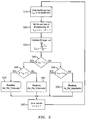
- FIG 5 is a flow chart illustrating the operation of each base station when performing load balancing updates. As mentioned previously, these load balancing updates occur relatively frequently compared to the coverage updates illustrated in Figure 6 .
- the local base station determines the current user load L 0,k (typically the number of active users being supported by the base station, but may also include other load metrics such as, for example, the transmission bandwidth being demanded by the supported users) in the current update slot, K.
- L 0,k typically the number of active users being supported by the base station, but may also include other load metrics such as, for example, the transmission bandwidth being demanded by the supported users
- This target load can then be used to provide an indication of whether the local base station is supporting more or less than the average load being supported by other base stations within the group.
- step S40 a determination is made as to whether the current user load L 0,k on the base station is greater than the target load L T,k for that base station. If the current user load L 0,k is less than the target load L T,k (meaning that the current user load is less than the maximum capacity of the base station C), then processing proceeds to step S45. At step S45, a determination is made as to whether the current user load L 0,k on the base station equals the target load L T,k for that base station. If the current user load L 0,K equals the target load L T,K , then no changes to the pilot channel transmission power and processing proceeds to step S90.
- step S50 If the current user load L 0,k is less than but not equal to the target load L T,k (meaning that the current user load is less than the maximum capacity of the base station C), then processing proceeds to step S50 where routine 3: Inc_Pwr_Underloaded (shown below) occurs because the base station is operating at less than the target level meaning that other base stations within the group are supporting a greater load and the local base station still has capacity to accept more load; the coverage area of the local base station is then increased by increasing the pilot channel transmission power to cause user equipment to handover from the more heavily loaded base stations within the group to the local base station, and processing proceeds to step S90. If the current user load L 0,K is greater than the target load L T,K , indicating that the base station is supporting greater than its share of load then processing proceeds to step S60.
- routine 3 Inc_Pwr_Underloaded (shown below) occurs because the base station is operating at less than the target level meaning that other base stations within the group are supporting a greater load and the local base station still has capacity to
- step S60 a determination is made of whether the current user load L 0,K is greater than the capacity C of the local base station. If the current user load L 0,K is greater than the capacity C of the local base station, then this indicates that the local base station is overloaded and needs to reduce its loading by handing-off user equipment; processing then proceeds to step S70 where routine 1: Dec_Pwr_Overloaded occurs. If the user load L 0,K is less than or equal to the capacity C of the local base station then processing proceeds to step S80 where routine 2 Dec_Pwr_Underloaded occurs whereby the local base station seeks to reduce its transmission power, but only when it is possible to do so; accordingly a determination is made of whether other base stations within the group are able to carry that load before any power reduction occurs.
- step S90 processing returns to step S10 to calculate the user load in the next slot.
- a local base station employs algorithms to adjust its user load to that of the calculated mean of all N neighbouring base stations. Given the current user load of the local base station, it collects via backhaul the user loads of its neighbours. It then computes the average load of the neighbour set (including its own load. Next, the local base station compares its current user load against the average load of the neighbour set, and decreases or increases its pilot transmission power to handover or acquire desired users, respectively. If the current user load is greater than its capacity (L0 > C; the overloaded case), it employs the routine Dec_Pwr_Overloaded to drop the extra users.
- the local base station uses the routine Dec_Pwr_Underloaded, which drops a user only if it can be picked up by another femtocell.
- the routine Inc_Pwr_Underloaded increases the BS's pilot transmission power to acquire the required number of users (L T -L 0 ).
- the minimum pilot channel transmission power threshold P tx , min thr is varied to help minimise coverage holes and any overlaps.
- a coverage metric is measured over a certain predetermined amount of time and the base station compares the measured metric against a predetermined threshold and decides to increase or decrease the minimum pilot channel transmission power threshold accordingly.
- An increase in the minimum pilot channel transmission power threshold P tx , min thr helps to remove coverage holes whilst a decrease in the minimum pilot channel transmission threshold P tx , min thr helps to minimise any coverage overlaps.
- the decrease step size P ⁇ step will be set to be much lower than the increment step size P ⁇ step to ensure that the base station coverage decreases gradually and that the coverage is dominated by the increment step. This is because coverage overlaps are less likely to adversely affect user equipment quality of service than coverage holes.
- step S100 the coverage metric ⁇ 0, k is measured.
- step S110 a determination is made as to whether the measured coverage metric ⁇ 0, k exceeds the predetermined threshold ⁇ 0 thr or not. If the measured coverage metric ⁇ 0, k does exceeds the threshold ⁇ 0 thr , indicating that an inadequate service is being provided to the user equipment, then the minimum pilot channel transmission power threshold P tx , min thr is increased by a predetermined step P step as step S120. If it is determined at step S110 that the measured coverage metric is less than or equal to the threshold ⁇ 0 thr , then processing proceeds to step S130.
- step S130 a determination is made of whether the current transmission power P tx equals the minimum pilot channel transmission power threshold P tx , min thr . If it does not, then no changes are made and processing proceeds to step S150. If it is determined that the pilot channel transmission power P tx equals the minimum pilot channel transmission power threshold P tx , min thr then, at step S140, the minimum pilot channel transmission power threshold P tx , min thr is reduced by a predetermined step P ⁇ step . Thereafter, processing proceeds step S150.
- step S150 further processing is suspended until the next update slot in B time periods.
- a decentralized joint coverage optimisation algorithm runs individually in each femtocell base station and works towards achieving user load balancing and minimization of coverage holes and overlap.
- Each base station stores thresholds for maximum pilot transmission power and minimum pilot transmission power.
- the maximum pilot power threshold is fixed and depends upon how much of the total base station transmission power is allocated to the pilot channel by the network designer.
- the minimum pilot power threshold is set adaptively by the algorithm.
- the algorithm which runs individually at each base station, consists of two update cycles; a more frequent pilot power transmission update to achieve user load balancing and an infrequent minimum pilot transmission threshold update to handle coverage hole and overlap minimization. The reason for more frequent load balancing updates is to cater for the mobility of the users and to converge to a balanced load before the users' positions change.
- program storage devices e.g., digital data storage media, which are machine or computer readable and encode machine-executable or computer-executable programs of instructions, wherein said instructions perform some or all of the steps of said above-described methods.
- the program storage devices may be, e.g., digital memories, magnetic storage media such as a magnetic disks and magnetic tapes, hard drives, or optically readable digital data storage media.
- the embodiments are also intended to cover computers programmed to perform said steps of the above-described methods.
- processors may be provided through the use of dedicated hardware as well as hardware capable of executing software in association with appropriate software.
- the functions may be provided by a single dedicated processor, by a single shared processor, or by a plurality of individual processors, some of which may be shared.
- processor or “controller” or “logic” should not be construed to refer exclusively to hardware capable of executing software, and may implicitly include, without limitation, digital signal processor (DSP) hardware, network processor, application specific integrated circuit (ASIC), field programmable gate array (FPGA), read only memory (ROM) for storing software, random access memory (RAM), and non volatile storage. Other hardware, conventional and/or custom, may also be included.
- DSP digital signal processor
- ASIC application specific integrated circuit
- FPGA field programmable gate array
- ROM read only memory
- RAM random access memory
- any switches shown in the Figures are conceptual only. Their function may be carried out through the operation of program logic, through dedicated logic, through the interaction of program control and dedicated logic, or even manually, the particular technique being selectable by the implementer as more specifically understood from the context.
- any block diagrams herein represent conceptual views of illustrative circuitry embodying the principles of the invention.
- any flow charts, flow diagrams, state transition diagrams, pseudo code, and the like represent various processes which may be substantially represented in computer readable medium and so executed by a computer or processor, whether or not such computer or processor is explicitly shown.
Landscapes
- Engineering & Computer Science (AREA)
- Computer Networks & Wireless Communication (AREA)
- Signal Processing (AREA)
- Mobile Radio Communication Systems (AREA)
Description
- The present invention relates to a base station, a method and a computer program product.
- In a cellular wireless telecommunications system, radio coverage is provided by areas known as cells. A base station is located in each cell to provide the radio coverage area. Traditional base stations provide coverage in relatively large geographical areas and these cells are often referred to as macro cells. It is possible to provide smaller sized cells, often within a macro cell. Such smaller sized cells are sometimes referred to as micro cells, pico cells or femto cells. Such small cells are typically established by providing a small cell base station that provides radio coverage having a relatively limited range within the radio coverage area of a macro cell. The transmission power of the small cell base station is relatively low and, hence, each small cell provides a smaller coverage area compared to that of a macro cell and covers, for example, an office or a home. A group of such small cell base stations may together provide a wireless small cell network.
- Such small cells are typically provided where the communications coverage provided by the macro cell is poor or where a user wishes to use an alternative communications link provided locally, by the small cell base station, to communicate with the core network. Such a situation might arise where, for example, a user has a pre-existing communications link and the user wishes to utilise that link in preference to that provided by a macro cell network provider to communicate with the core network. The group of small cell base stations providing the wireless small cell network can together provide extended local coverage to user equipment throughout, for example, a home or an office building by using multiple small cell base stations distributed throughout those buildings which enables each of those base stations to transmit at a lower power than would otherwise be necessary if coverage was to be provided by a single small cell base station.
- However, the proliferation of the deployment of base stations makes the control of base stations difficult to achieve.
US 2008/0181184 A1 discloses methods and apparatus for use in controlling the loading of wireless access points in a wireless local area network. An indication, which indicates whether a loading of an overloaded wireless access point is grater than a predetermined threshold, is identified. When the indication indicates that the loading is greater than a predetermined threshold, a transmission power of another wireless access point is increased in order to increase its radio coverage area. The transmission power of the overloaded wireless access point is reduced in order to reduce a coverage are of that wireless access point. When the coverage area of the wireless access point reaches the lower threshold specified by a minimum transmit power, the wireless access point is prevented from decreasing its transmit power any further. Some of the mobile communications devices then switch between wireless access points in order to reduce loading of the overloaded wireless access point. - Accordingly, it is desired to provide an improved technique for controlling base stations.
- According to a first aspect there is provided a base station as claimed in
claim 1. The first aspect recognises that radio coverage optimisation of base stations is an important element in improving the overall performance of each of the base stations within a group. A group of base stations with co-ordinated and optimised coverage can achieve higher end user data rates and improved quality of service than would otherwise be possible. However, the first aspect also recognises that achieving optimised coverage requires careful trade-offs to be made in order to accommodate conflicting objectives. Furthermore, since the network provider may have little or no control over the exact locations of each individual base station, the first aspect recognises that coordinating the coverage areas becomes difficult to achieve. - Existing techniques for coverage optimisation generally utilise centralised computation approaches to determine base station configurations for the network. However, the first aspect recognises that utilising such an approach would require each base station to communicate with a central entity which would significantly increase the amount of signalling data being transmitted throughout the network. Also, such an approach would require either accurate information on the location and configuration of the base stations to be provided by the installer of that base station or complex functionality to be provided in the base stations to enable those base stations to provide that information automatically. However, if that information is inaccurate or incomplete, then optimisation of coverage areas may not be possible to achieve. Accordingly, a technique is provided where distributed joint coverage optimisation is achieved between base stations. Although this technique has particular utility to base stations deployed in wireless small cell networks, it will be appreciated that similar functionality would also be beneficial in other base stations or network nodes such as, for example, macro base stations.
- Hence, a base station is provided which may operate together with other base stations within a group such as, for example, a wireless small cell network, to support wireless communications with user equipment. Transmission logic is provided which may generate a cell such as, for example, a macro cell, micro cell, pico cell or femto cell which has a coverage area which supports wireless communications with user equipment. Reception logic is provided which may receive information regarding the communications load being experienced by other base stations within the group. Coverage area adjustment logic is provided which may determine those changes required to the coverage area to vary the communications load experienced by base stations within the group. In this way, it can be seen that each base station within the group may receive information about the user loading on other base stations within that group and is able to adjust its coverage area to cause that communications loading to be rebalanced to enable efficient use of resources and optimise the overall performance of each of the base stations within the group. By co-ordinating within the group, the need to obtain and communicate accurate configuration and location information to a central entity is obviated. Instead, optimised coverage can be achieved through trade-offs made locally to accommodate conflicting local objectives. It will be appreciated that the load information may be obtained from neighbouring base stations within the group either directly or via another network node such as, for example, a gateway or may be obtained from measurement reports communicated by the user equipment. The group of base stations with co-ordinated and optimised coverage can achieve higher end user data rates and improved quality of service than would otherwise be possible.
- The coverage area adjustment logic is operable to determine changes required the coverage area within a predetermined range bounded by an upper and lower threshold. Hence, the extent to which changes can be made may generally be restricted to within a particular range to help improve the stability and convergence of the overall system.
- In one embodiment, the coverage area adjustment logic is operable, when the user equipment communications load supported by the base station is below an average user equipment communications load for the group but fails to exceed a predetermined maximum user equipment communications load supportable by the base station, to increase the coverage area to no more than a maximum coverage area defined by the upper threshold of the predetermined range to increase the user equipment communications load experienced by the base station. Accordingly, should it be determined that the load currently being supported by the base station is less than the maximum load which the base station can support and is also less than the average load for base stations within that group, then this is likely to indicate that that the base station still has capacity to take on more load and that other base stations are carrying more than their fair share of load. Hence, the coverage area of that base station may be increased. Increasing the coverage area is likely to cause user equipment which currently exerts a communications load on a neighbouring base station to handover to this base station thereby rebalancing the load on base stations within the group. Also, by ensuring that the increase in coverage does not exceed the maximum threshold, the maximum coverage area of that base station can be restrained to prevent any one base station unnecessarily dominating an area which may otherwise cause a detrimental effect on the overall performance of the network.
- The coverage area adjustment logic is operable, when the user equipment communications load experienced by the base station is above an average user equipment communications load for the group and exceeds a predetermined maximum user equipment communications load supportable by the base station, to decrease the coverage area to decrease the user equipment communications load experienced by the base station. Accordingly, should it be determined that the load currently being supported by the base station exceeds the maximum load which the base station can support and is also above the average load of base stations within the group, then this is likely to indicate that that the base station still has no capacity to take on more load and that other base stations are carrying less than their fair share of load. Hence, the coverage area of that base station is decreased. Decreasing the coverage area of the base station is likely to cause user equipment exerting a load on that base station to handover to another base station within that group, again rebalancing the load between base stations within the group.
- The coverage area adjustment logic is operable, when the decrease in the coverage area is to below the lower threshold, to reduce the lower threshold. It will be appreciated that if the decreased coverage area provides a coverage area which is less that the lower threshold, then it is likely that the lower threshold may be too high for the currently loading since that base stations is exceeding its capacity and supporting more user load than others within the group. By reducing the lower threshold, the coverage area may be reduced to an amount which enables reasonable operation of that base station and helps to rebalance the loading.
- In one embodiment, the coverage area adjustment logic is operable, when the user equipment communications load experienced by the base station is above an average user equipment communications load for the group but fails to exceed a predetermined maximum user equipment communications load experienced by the base station and when base stations identified from the load information as being candidates to support user equipment communications load which would no longer be supported by the base station fail to exceed a predetermined maximum user equipment communications load supportable by those base stations, to decrease the coverage area to no less than a minimum coverage area defined by the lower threshold of the predetermined range to decrease user equipment communications load experienced by the base station. Accordingly, it is determined whether the current loading on the base station is less than the maximum loading for that base station but exceeds the average loading for the group, thereby indicating that the base station is more heavily loaded than it need be. However, rather than simply decrease its coverage area, a further determination is made as to whether those base stations which would experience an increase in load should be coverage area of this base station be reduced have the capacity to take on that additional load. Only if those base stations do have the capacity to take the additional load may the coverage area be decreased. Otherwise, no changes in the coverage area may be made since the base station still has sufficient capacity to accommodate the additional loading. In this way it can be seen that a decrease in coverage area may only occur when it is not overly detrimental to do so to other base stations within the group.
- In one embodiment, the reception logic is operable to receive receiver sensitivity information indicative of a sensitivity of receivers of user equipment supported by base stations within the group and the coverage area adjustment logic is operable to determine from the receiver sensitivity information whether the decrease to the coverage area would cause user equipment communications load to no longer be supported by the base stations within the group and, if so, to prevent the decrease. Accordingly, information regarding the sensitivity of receivers of the user equipment being supported by base stations within the group may be provided. It will be appreciated that this information may be provided by the user equipment themselves and communicated to base stations either directly, via the base stations to which the user equipment are attached, or via some other network node. A decrease in the coverage area of the base station may be prevented should it be determined from the receiver sensitivity information that doing so would cause user equipment to no longer be supported by the base stations within the group. It will be appreciated that if that would be allowed to occur, then either the user equipment would experience a dropped call or this may cause the user equipment to be handed back to any overlying cell such as, for example, a macro cell within which the group is located.
- In one embodiment, the load information indicative of a user equipment communications load experienced by base stations within the group comprises information indicative of numbers of user equipment supported by the base stations within the group and the coverage area adjustment logic is operable to determine changes required to the coverage area by changing its pilot channel transmission power to change the user equipment communications load experienced by at least one base station within the group by changing numbers of users supported by the at least one base station within the group. Accordingly, the number of user equipment supported by the base stations may be provided. Changes in the pilot transmission power level may be utilised to vary the coverage area. It will be appreciated that increasing or decreasing the pilot channel transmission power may cause the number of user equipment being supported by base stations to be increased or decreased.
- In one embodiment, the predetermined range bounded by an upper and lower threshold comprises a predetermined pilot channel transmission power range bounded by an upper pilot channel transmission power threshold and a lower pilot channel transmission power threshold. Accordingly, upon receiving user load information from each of its neighbouring base stations, the base station may compute the average user load shared by all base stations. The difference between the base station's current load and the average load shared by all the base stations represents a target number of users to be adjusted within its coverage area. The base station may then adjust its pilot transmission power (and consequentially its coverage) within the threshold of the minimum pilot transmission power and the maximum transmission power to acquire or handover the desired number of users to or from other base stations. The maximum pilot transmission power threshold is typically fixed and depends on how much of the total base station transmission power is allocated to the pilot channel by the network operator, whereas the lower threshold may be varied to suit the individual operating conditions of that base station.
- In one embodiment, the coverage area adjustment logic is operable, when the number of user equipment supported by the base station is below an average number of user equipment supported by base stations within the group but fails to exceed a predetermined maximum number of user equipment supportable by the base station, to increase the coverage area to no more than a maximum coverage area defined by the upper threshold of the predetermined range to increase the number of user equipment supported by the base station. By increasing the pilot channel transmission power it is likely that user equipment which are currently being supported by other base stations within the group may handover to that base station, thereby reducing the number of user equipment being supported by those other base stations and increasing the number or user equipment being supported by this base station. Also, by increasing the pilot channel transmission power any coverage holes which may otherwise exist can be filled.
- In one embodiment, the coverage area adjustment logic is operable, when the number of user equipment supported by the base station is above an average number of user equipment supported by base stations within the group and exceeds a predetermined maximum number of user equipment supportable by the base station, to decrease the coverage area to decrease the number of user equipment supported by the base station. By decreasing the pilot channel transmission power it is likely that user equipment which are currently being supported by that base station may handover to other base stations within the group, thereby reducing the number of user equipment being supported by that base station and increasing the number or user equipment being supported by other base stations within the group. Also, decreasing the pilot channel transmission power helps to minimise any coverage overlap which may exist between neighbouring base stations.
- In one embodiment, the coverage area adjustment logic is operable, when the number of user equipment supported by the base station is above an average number of user equipment supported by base stations within the group but fails to exceed a predetermined maximum number of user equipment supportable the base station and when base stations identified from the information indicative of numbers of user equipment supported by the base stations as being candidates to support user equipment which would no longer be supported by the base station fail to exceed a predetermined maximum number of user equipment supportable by those base stations, to decrease the coverage area to no less than a minimum coverage area defined by the lower threshold of the predetermined range to decrease the number of user equipment supported by the base station.
- In one embodiment, the reception logic is operable to receive an indication of quality of service provided to user equipment supported by the base station and the coverage area adjustment logic is operable to adjust the lower threshold of the predetermined range to vary the minimum coverage area definable by the predetermined range in response to the indication. By utilising a measured coverage metric such as, for example, the quality of service, over a specified amount of time, an assessment can be made of the overall coverage provided by the base stations within the group to help minimise coverage holes and/or overlap.
- In one embodiment, the coverage area adjustment logic is operable to perform at least one of: when the indication of quality of service indicates that less than or equal to a predetermined quality of service is being provided to user equipment supported by the base station, to increase the lower threshold of the predetermined range by a first predetermined amount; and when the indication of quality of service indicates that greater than a predetermined quality of service is being provided to user equipment supported by the base station, to decrease the lower threshold of the predetermined range by a second predetermined amount. Accordingly, the threshold may be incremented to help to remove coverage holes whilst the threshold may be decremented to help to minimise any coverage overlap. It will be appreciated that a base station's coverage area may typically be the geographical region where its transmitted signal can be received by user equipment at a signal strength that is greater than some specified threshold. A coverage gap represents the area where the received base station signal is typically below the specified threshold, whereas a coverage overlap denotes the region where two or more base stations signals are received by user equipment above the specified threshold.
- In one embodiment, the first predetermined amount is greater than the second predetermined amount. Setting the decrement step to be much lower than the increment step helps to ensure that the coverage is dominated by the increment step and that coverage is decreased gradually. Accordingly, the base station may monitor the value of a coverage metric (for example a metric incorporating the users call drop probability or a coverage overlap coefficient) over a specified amount of time. If the measured value of the specified metric exceeds a corresponding maximum allowable threshold, then the base station's minimum pilot transmission power threshold may be increased typically by a fixed step size. However, if the measured metric value is less than the maximum allowable threshold, then the base station's minimum pilot transmission power threshold may be reduced gradually.
- In one embodiment, the coverage area adjustment logic is operable to asses whether changes are required to the lower threshold based on the indication of quality of service less frequently than whether changes are required to the coverage area based on the load information. Accordingly, the rate at which the lower threshold is assessed may be much lower that the rate at which the coverage area is assessed to help improve convergence of the system. Accordingly, the minimum pilot transmission power threshold is set adaptively by the algorithm which runs individually on each base station and consists of two update cycles, a more frequent pilot transmission power update, which achieves user load balancing, and a less frequent minimum pilot transmit power threshold update to minimise coverage holes and overlap.
- According to a second aspect of the present invention, there is provided a method, as claimed in Claim 12.
- In one embodiment, the step of determining comprises: when the user equipment communications load supported by the base station is below an average user equipment communications load for the group but fails to exceed a predetermined maximum user equipment communications load supportable by the base station, increasing the coverage area to no more than a maximum coverage area defined by the upper threshold of the predetermined range to increase the user equipment communications load experienced by the base station.
- In one embodiment, the step of determining comprises: when the user equipment communications load experienced by the base station is above an average user equipment communications load for the group but fails to exceed a predetermined maximum user equipment communications load experienced the base station and when base stations identified from the load information as being candidates to support user equipment communications load which would no longer be supported by the base station fail to exceed a predetermined maximum user equipment communications load supportable by those base stations, decreasing the coverage area to no less than a minimum coverage area defined by the lower threshold of the predetermined range to decrease user equipment communications load experienced by the base station.
- In one embodiment, the step of receiving comprises: receiving receiver sensitivity information indicative of a sensitivity of receivers of user equipment supported by base stations within the group and the step of determining comprises: determining from the receiver sensitivity information whether the decrease to the coverage area would cause user equipment communications load to no longer be supported by the base stations within the group and, if so, to prevent the decrease.
- In one embodiment, the load information indicative of a user equipment communications load experienced by base stations within the group comprises information indicative of numbers of user equipment supported by the base stations within the group and the step of determining comprises: determining changes required to the coverage area by changing its pilot channel transmission power to change the user equipment communications load experienced by at least one base station within the group by changing numbers of users supported by the at least one base station within the group.
- In one embodiment, the predetermined range bounded by an upper and lower threshold comprises a predetermined pilot channel transmission power range bounded by an upper pilot channel transmission power threshold and a lower pilot channel transmission power threshold.
- In one embodiment, the step of determining comprises: when the number of user equipment supported by the base station is below an average number of user equipment supported by base stations within the group but fails to exceed a predetermined maximum number of user equipment supportable by the base station, increasing the coverage area to no more than a maximum coverage area defined by the upper threshold of the predetermined range to increase the number of user equipment supported by the base station.
- In one embodiment, the step of determining comprises: when the number of user equipment supported by the base station is above an average number of user equipment supported by base stations within the group and exceeds a predetermined maximum number of user equipment supportable by the base station, decreasing the coverage area to decrease the number of user equipment supported by the base station.
- In one embodiment, the step of determining comprises: when the number of user equipment supported by the base station is above an average number of user equipment supported by base stations within the group but fails to exceed a predetermined maximum number of user equipment supportable the base station and when base stations identified from the information indicative of numbers of user equipment supported by the base stations as being candidates to support user equipment which would no longer be supported by the base station fail to exceed a predetermined maximum number of user equipment supportable by those base stations, decreasing the coverage area to no less than a minimum coverage area defined by the lower threshold of the predetermined range to decrease the number of user equipment supported by the base station.
- In one embodiment, the step of receiving comprises: receiving an indication of quality of service provided to user equipment supported by the base station and the step of determining comprises: adjusting the lower threshold of the predetermined range to vary the minimum coverage area definable by the predetermined range in response to the indication.
- in one embodiment, the step of determining comprises at least one of: when the indication of quality of service indicates that less than or equal to a predetermined quality of service is being provided to user equipment supported by the base station, increasing the lower threshold of the predetermined range by a first predetermined amount; and when the indication of quality of service indicates that greater than a predetermined quality of service is being provided to user equipment supported by the base station, decreasing the lower threshold of the predetermined range by a second predetermined amount.
- In one embodiment, the first predetermined amount is greater than the second predetermined amount.
- In one embodiment, the step of determining comprises assessing whether changes are required to the lower threshold based on the indication of quality of service less frequently than whether changes are required to the coverage area based on the load information.
- According to a third aspect of the present invention, there is provided a computer program product operable, when executed on a computer, to perform the method steps of the second aspect.
- Further particular and preferred aspects are set out in the accompanying independent and dependent claims. Features of the dependent claims may be combined with features of the independent claims as appropriate, and in combinations other than those explicitly set out in the claims.
- Embodiments of the present invention will now be described further, with reference to the accompanying drawings, in which:
-
Figure 1 illustrates the main components of a telecommunications network according to one embodiment; -
Figure 2 illustrates a general femto cell deployment within one macro cell shown inFigure 1 ; -
Figure 3 illustrates in more detail a specific femto cell deployment within the wireless communications network ofFigure 1 ; -
Figure 4 illustrates schematically the update cycles; -
Figure 5 is a flowchart illustrating the main processing steps of the load balancing updates; and -
Figure 6 is a flowchart illustrating the main processing steps of the coverage updates. -
Figure 1 illustrates a wireless communication system, generally 10, according to one embodiment.User equipment 44 roam through thewireless communication system 10.Base stations 22 are provided which support respectivemacro cells 24. A number of such base stations are provided, which are distributed geographically in order to provide a wide area of coverage to theuser equipment 44. Whenuser equipment 44 is within amacro cell 24 supported by thebase station 22 then communications may be established between theuser equipment 44 and thebase station 22 over an associated radio link. Each base station typically supports a number of sectors. Typically, a different antenna within a base station supports an associated sector. Of course, it will be appreciated thatFigure 1 illustrates a small subset of the total number of user equipment and base stations that may be present in a typical communications system. - The
wireless communication system 10 is managed by aradio network controller 170. Theradio network controller 170 controls the operation of thewireless communications system 10 by communicating with thebase stations 22 over a backhaul communications link 160. Thenetwork controller 170 also communicates with theuser equipment 44 via their respective radio links in order to efficiently manage thewireless communication system 10. - The
radio network controller 170 maintains a neighbour list which includes information about the geographical relationship between cells supported by base stations. In addition, theradio network controller 170 maintains location information which provides information on the location of the user equipment within thewireless communications system 10. Theradio network controller 170 is operable to route traffic via circuit-switched and packet-switched networks. Hence, amobile switching centre 250 is provided with which theradio network controller 170 may communicate. Themobile switching centre 250 then communicates with a circuit-switched network such as a public switched telephone network (PSTN) 210. Likewise, thenetwork controller 170 communicates with service general packet radio service support nodes (SGSNs) 220 and a gateway general packet radio support node (GGSN) 180. The GGSN then communicates with a packet-switch core 190 such as, for example, the Internet. - As shown in more detail in
Figure 2 , there are provided small cell base stations, in this example femto cell base stations FA to FC, each of which provides a femto cell A to C in the vicinity of a building within which the associated femto cell base station is installed. The femto cells A to C provide local communications coverage for a user in the vicinity of those buildings. Each femto cell base station FA to FC communicates via a femtocell controller/gateway 230. A handover or camping event occurs between thebase station 22 and the femto cell base stations FA to FC when the femto base stations FA to FC detect that user equipment comes within range. The femto cell base stations FA to FC typically utilise the user's broadband Internet connection 240 (such as ADSL, Cable, Ethernet, etc.) as a backhaul. - Femto cell base stations FA to Fc are lower-power, low-cost, user-deployed base stations that provide a high cellular quality of service in residential or enterprise environment. In contrast to current macro cell approaches where complex and highly reliable base stations are deployed to strategic locations decided by the network owner, the femto cell base stations FA to FC are provided locally by customers. Such femto cell base stations FA to FC provide local coverage in areas of the macro network where quality of service may be low. Hence, the femto cell base stations FA to FC provide for improved quality of service in areas which are difficult for network operators. To reduce the cost of the femto base stations FA to FC and to reduce complexity and interference effects of the femto cell on other user equipment within the macro cell, the transmission power of the femto cell base station FA to FC is relatively low in order to restrict the size of the femto cell to a range of tens of metres or less. The femto cell base stations FA to FC have extensive auto-configuration and self-optimisation capability to enable a simply plug-and-play deployment. As such, they are designed to automatically integrate themselves into an existing macro
cellular wireless network 10. -
Figure 3 illustrates a cluster or group of femto base stations FA to FC jointly providing coverage in an intended geographical area. The group of femto base stations form a wireless small cell network. The wireless small cell network is provided typically within an underlyingmacro cell 24. The underlyingmacro cell 2 is intended to cater for high mobility users and a wide geographical coverage area. The group of femto base stations forming the wireless small cell network is intended to provide local coverage to user equipment. When user equipment move between the different femto cells A to C forming the wireless small cell network, it is desired that the user equipment remains supported by those femto base stations and avoids being handed over to the underlyingmacro cell 24. - Each base station's coverage area is the geographical region where the transmitted signal can be received by a user equipments receiver at a signal strength which is greater than some specified threshold. Of course, the coverage will depend on may factors such as, for example, the transmission strength of the signal, the sensitivity of the receiver at the user equipment, the attenuation between the transmitter and the receiver, as well as any other noise or interference experienced. Hence, the
area 11 is a coverage gap or hole where the received signal from each of the femto base stations is below that specified threshold. Theoverlap areas - The technique disclosed herein seeks to perform optimisation within the wireless small cell network by varying the coverage area provided by each base station in a way which seeks to meet the following objectives. The first is to balance the user load amongst the co-located base stations to enable efficient utilisation of radio resources. The second is to minimise any radio coverage holes or gaps within the wireless small cell network. The third is to minimise any coverage overlap between neighbouring base stations; in other words to achieve the first two objectives with a minimum possible transmission power. Local status information available to each base stations is used to perform this optimisation. This information is obtained from measurement reports communicated back to the base stations by connected user equipment and/or from information provided by neighbouring base stations either directly or via a central node such as, for example, the femto controller/
gateway 230. Each base station then makes use of this information and, based on predefined algorithms, makes a local decision to help the wireless small cell network collectively to better achieve those objectives. In particular, each base station performs frequent updates to its pilot channel transmission power to vary the coverage area of that base station, thereby adjusting the load on that base station and/or on neighbouring base stations. - Each base station stores thresholds for maximum pilot channel transmission power and minimum pilot channel transmission power. The maximum pilot channel transmission power threshold is fixed and depends on how much of the total base station transmission power is allocated to the pilot channel by the network designer. The minimum pilot power transmission threshold is set adaptively by the predefined algorithms. Pilot channel transmission power updates occur more frequently and adjust the level of the pilot channel transmission power within these two thresholds. Minimum pilot channel transmission power threshold updates occur less frequently, as illustrated schematically in
Figure 4 . - Each base station, upon receiving user load information relating to neighbouring base stations, computes the average user load shared by those base stations. The difference between the base stations current load and the average load shared by the neighbouring base stations represents the target number of users to be adjusted within the base stations coverage area. The base station then, if appropriate, adjusts its pilot channel transmission power, and consequently its coverage, within the thresholds to acquire or handover the desired number of users to a neighbouring base station in order to rebalance the load, as will be described in more detail below.
- Each base station also monitors the value of the coverage metric such as a metric incorporating a call drop probability and/or a coverage overlap coefficient and/or another quality of service metric over a specified amount of time. If the measured value of the specified metric exceeds a corresponding maximum allowable threshold, the base station's minimum pilot channel transmission power threshold is increased by a particular step size because exceeding the desired threshold indicates inadequate coverage. However, if the measured metric is less than the maximum allowable threshold, the base station's minimum pilot channel transmission power threshold is reduced gradually since greater than an adequate quality of service is being provided to user equipment and it may be that the base station can reduce its transmission power.
- As shown in
Figure 3 , each base station FA, FB, FC is operable to communicate and/or sense the neighbouring base stations within the group. To improve clarity of the following description and by way of example, the base station FA will be referred to as the "local" base station. The neighbouring base station FB and FC will the referred to as neighbouring base stations. The local base station FA is operable to perform pilot channel signal measurements to detect the neighbouring base stations that are located nearby either directly or through measurement reports. The local base station FA can also perform query and respond procedures over the backhaul network to obtain information about its neighbours either directly from those neighbouring base stations or from information stored centrally by the femto cell controller/gateway 230. In any event, the neighbouring base stations are those whose pilot channel power changes can have a significant impact on the local base station performance and visa versa. - As mentioned above, each base station periodically gathers information from supported user equipment and neighbouring base stations the base station then periodically adjusts its pilot channel transmission power lower threshold periodically to minimise coverage holes and any overlaps. Each base station also performs more frequently changes to its pilot channel transmission power within the set upper and lower thresholds to balance the load experienced between neighbouring base stations within the wireless small cell network, as will now be described in more detail.
-
Figure 5 is a flow chart illustrating the operation of each base station when performing load balancing updates. As mentioned previously, these load balancing updates occur relatively frequently compared to the coverage updates illustrated inFigure 6 . - At step S10, the local base station determines the current user load L0,k (typically the number of active users being supported by the base station, but may also include other load metrics such as, for example, the transmission bandwidth being demanded by the supported users) in the current update slot, K.
- At step S20, the local base station determines the loads Li,K of each of the neighbouring base stations, where i = 1 to N-1, and N is the total number of base stations in a neighbour cluster or group (for example N is 3 in the example shown in
Figure 3 ). - At step S30, the local base station then calculates a base station target load in accordance with the algorithm

- At step S40, a determination is made as to whether the current user load L0,k on the base station is greater than the target load LT,k for that base station. If the current user load L0,k is less than the target load LT,k (meaning that the current user load is less than the maximum capacity of the base station C), then processing proceeds to step S45. At step S45, a determination is made as to whether the current user load L0,k on the base station equals the target load LT,k for that base station. If the current user load L0,K equals the target load LT,K, then no changes to the pilot channel transmission power and processing proceeds to step S90. If the current user load L0,k is less than but not equal to the target load LT,k (meaning that the current user load is less than the maximum capacity of the base station C), then processing proceeds to step S50 where routine 3: Inc_Pwr_Underloaded (shown below) occurs because the base station is operating at less than the target level meaning that other base stations within the group are supporting a greater load and the local base station still has capacity to accept more load; the coverage area of the local base station is then increased by increasing the pilot channel transmission power to cause user equipment to handover from the more heavily loaded base stations within the group to the local base station, and processing proceeds to step S90. If the current user load L0,K is greater than the target load LT,K, indicating that the base station is supporting greater than its share of load then processing proceeds to step S60.
- At step S60, a determination is made of whether the current user load L0,K is greater than the capacity C of the local base station. If the current user load L0,K is greater than the capacity C of the local base station, then this indicates that the local base station is overloaded and needs to reduce its loading by handing-off user equipment; processing then proceeds to step S70 where routine 1: Dec_Pwr_Overloaded occurs. If the user load L0,K is less than or equal to the capacity C of the local base station then processing proceeds to step S80 where routine 2 Dec_Pwr_Underloaded occurs whereby the local base station seeks to reduce its transmission power, but only when it is possible to do so; accordingly a determination is made of whether other base stations within the group are able to carry that load before any power reduction occurs.
- At step S90, processing returns to step S10 to calculate the user load in the next slot.
-

-


-

- Hence, it can be seen that a local base station employs algorithms to adjust its user load to that of the calculated mean of all N neighbouring base stations. Given the current user load of the local base station, it collects via backhaul the user loads of its neighbours. It then computes the average load of the neighbour set (including its own load. Next, the local base station compares its current user load against the average load of the neighbour set, and decreases or increases its pilot transmission power to handover or acquire desired users, respectively. If the current user load is greater than its capacity (L0 > C; the overloaded case), it employs the routine Dec_Pwr_Overloaded to drop the extra users. For the case (C, L0 > LT), the local base station uses the routine Dec_Pwr_Underloaded, which drops a user only if it can be picked up by another femtocell. For the underloaded case (L0 < LT), the routine Inc_Pwr_Underloaded increases the BS's pilot transmission power to acquire the required number of users (LT-L0).
- As mentioned above, periodically, the minimum pilot channel transmission power threshold


- Turning now to
Figure 6 , at step S100, the coverage metric ζ 0,k is measured. - At step S110, a determination is made as to whether the measured coverage metric ζ 0,k exceeds the
predetermined threshold 
threshold 

threshold 
- At step S130, a determination is made of whether the current transmission power Ptx equals the minimum pilot channel transmission power threshold


- At step S150, further processing is suspended until the next update slot in B time periods.
- Hence, it can be seen that In contrast to centralized approaches, decentralized/distributed algorithms are utilised which allow base stations to take local decisions to achieve a global objective. A decentralized joint coverage optimisation algorithm runs individually in each femtocell base station and works towards achieving user load balancing and minimization of coverage holes and overlap. Each base station stores thresholds for maximum pilot transmission power and minimum pilot transmission power. The maximum pilot power threshold is fixed and depends upon how much of the total base station transmission power is allocated to the pilot channel by the network designer. The minimum pilot power threshold is set adaptively by the algorithm. The algorithm, which runs individually at each base station, consists of two update cycles; a more frequent pilot power transmission update to achieve user load balancing and an infrequent minimum pilot transmission threshold update to handle coverage hole and overlap minimization. The reason for more frequent load balancing updates is to cater for the mobility of the users and to converge to a balanced load before the users' positions change.
-
- N - The total number of base stations in a neighbor cluster, such that each base station has N-1 neighbors.
- C - Base station capacity (e.g. maximum number of active users).
- η - mobile receiver's receiver sensitivity.
- L 0 - User load (number of active users) for the base station currently updating.
- LT - Target user load for the base station currently updating.
-

-

- ξthr - Threshold for the coverage holes metric ξ.
- Prx - Received Pilot Signal Strength (RPSS).
- Prx,L - Lowest Received Pilot Signal Strength.
-

-

-

-

- A person of skill in the art would readily recognize that steps of various above-described methods can be performed by programmed computers. Herein, some embodiments are also intended to cover program storage devices, e.g., digital data storage media, which are machine or computer readable and encode machine-executable or computer-executable programs of instructions, wherein said instructions perform some or all of the steps of said above-described methods. The program storage devices may be, e.g., digital memories, magnetic storage media such as a magnetic disks and magnetic tapes, hard drives, or optically readable digital data storage media. The embodiments are also intended to cover computers programmed to perform said steps of the above-described methods.
- The functions of the various elements shown in the Figures, including any functional blocks labelled as "processors" or "logic", may be provided through the use of dedicated hardware as well as hardware capable of executing software in association with appropriate software. When provided by a processor, the functions may be provided by a single dedicated processor, by a single shared processor, or by a plurality of individual processors, some of which may be shared. Moreover, explicit use of the term "processor" or "controller" or "logic" should not be construed to refer exclusively to hardware capable of executing software, and may implicitly include, without limitation, digital signal processor (DSP) hardware, network processor, application specific integrated circuit (ASIC), field programmable gate array (FPGA), read only memory (ROM) for storing software, random access memory (RAM), and non volatile storage. Other hardware, conventional and/or custom, may also be included. Similarly, any switches shown in the Figures are conceptual only. Their function may be carried out through the operation of program logic, through dedicated logic, through the interaction of program control and dedicated logic, or even manually, the particular technique being selectable by the implementer as more specifically understood from the context.
- It should be appreciated by those skilled in the art that any block diagrams herein represent conceptual views of illustrative circuitry embodying the principles of the invention. Similarly, it will be appreciated that any flow charts, flow diagrams, state transition diagrams, pseudo code, and the like represent various processes which may be substantially represented in computer readable medium and so executed by a computer or processor, whether or not such computer or processor is explicitly shown.
- The description and drawings merely illustrate the principles of the invention. It will thus be appreciated that those skilled in the art will be able to devise various arrangements that, although not explicitly described or shown herein, embody the principles of the invention and are included within its scope. Furthermore, all examples recited herein are principally intended expressly to be only for pedagogical purposes to aid the reader in understanding the principles of the invention and the concepts contributed by the inventor(s) to furthering the art, and are to be construed as being without limitation to such specifically recited examples and conditions. Moreover, all statements herein reciting principles, aspects, and embodiments of the invention, as well as specific examples thereof, are intended to encompass equivalents thereof.
Claims (13)
- A base station (FA; FB; FC) operable, in concert with other base stations within a group (FA. FB, FC), to support wireless communications with user equipment (44), said base station comprising:transmission logic operable to generate a cell (A; B; C) having a coverage area supporting wireless communications with user equipment;reception logic operable to receive load information indicative of a user equipment communications load experienced by base stations within said group; andcoverage area adjustment logic operable to determine changes required to said coverage area within a predetermined range bounded by an upper and lower threshold to change a user equipment communications load experienced by at least one base station within said group and, when said user equipment communications load experienced by said base station is above an average user equipment communications load for said group and exceeds a predetermined maximum user equipment communications load supportable by said base station, to decrease said coverage area to decrease said user equipment communications load experienced by said base station and, when said decrease in said coverage area is to below said lower threshold, to reduce said lower threshold.
- The base station as claimed in claim 1, wherein said coverage area adjustment logic is operable, when said user equipment communications load supported by said base station is below an average user equipment communications load for said group but fails to exceed a predetermined maximum user equipment communications load supportable by said base station, to increase said coverage area to no more than a maximum coverage area defined by said upper threshold of said predetermined range to increase said user equipment communications load experienced by said base station.
- The base station as claimed in claims 1 or 2, wherein said coverage area adjustment logic is operable, when said user equipment communications load experienced by said base station is above an average user equipment communications load for said group but fails to exceed a predetermined maximum user equipment communications load experienced said base station and when base stations identified from said load information as being candidates to support user equipment communications load which would no longer be supported by said base station fail to exceed a predetermined maximum user equipment communications load supportable by those base stations, to decrease said coverage area to no less than a minimum coverage area defined by said lower threshold of said predetermined range to decrease user equipment communications load experienced by said base station.
- The base station as claimed in claim 3, wherein said reception logic is operable to receive receiver sensitivity information indicative of a sensitivity of receivers of user equipment supported by base stations within said group and said coverage area adjustment logic is operable to determine from said receiver sensitivity information whether said decrease to said coverage area would cause user equipment communications load to no longer be supported by said base stations within said group and, if so, to prevent said decrease.
- The base station as claimed in any preceding claim, wherein said load information indicative of a user equipment communications load experienced by base stations within said group comprises information indicative of numbers of user equipment supported by said base stations within said group and said coverage area adjustment logic is operable to determine changes required to said coverage area by changing its pilot channel transmission power to change said user equipment communications load experienced by at least one base station within said group by changing numbers of users supported by said at least one base station within said group.
- The base station as claimed in claim 5, wherein said predetermined range bounded by said upper and lower threshold comprises a predetermined pilot channel transmission power range bounded by an upper pilot channel transmission power threshold and a lower pilot channel transmission power threshold.
- The base station as claimed in claims 5 or 6, wherein said coverage area adjustment logic is operable, when said number of user equipment supported by said base station is below an average number of user equipment supported by base stations within said group but fails to exceed a predetermined maximum number of user equipment supportable by said base station, to increase said coverage area to no more than a maximum coverage area defined by said upper threshold of said predetermined range to increase said number of user equipment supported by said base station.
- The base station as claimed in any one of claims 5 to 7, wherein said coverage area adjustment logic is operable, when said number of user equipment supported by said base station is above an average number of user equipment supported by base stations within said group and exceeds a predetermined maximum number of user equipment supportable by said base station, to decrease said coverage area to decrease said number of user equipment supported by said base station.
- The base station as claimed in any one of claims 5 to 8, wherein said coverage area adjustment logic is operable, when said number of user equipment supported by said base station is above an average number of user equipment supported by base stations within said group but fails to exceed a predetermined maximum number of user equipment supportable said base station and when base stations identified from said information indicative of numbers of user equipment supported by said base stations as being candidates to support user equipment which would no longer be supported by said base station fail to exceed a predetermined maximum number of user equipment supportable by those base stations, to decrease said coverage area to no less than a minimum coverage area defined by said lower threshold of said predetermined range to decrease said number of user equipment supported by said base station.
- The base station as claimed in any one of claims 1 to 9, wherein said reception logic is operable to receive an indication of quality of service provided to user equipment supported by said base station and said coverage area adjustment logic operable to adjust said lower threshold of said predetermined range to vary said minimum coverage area definable by said predetermined range in response to said indication.
- The base station as claimed in claim 10, wherein said coverage area adjustment logic is operable to perform at least one of:when said indication of quality of service indicates that less than or equal to a predetermined quality of service is being provided to user equipment supported by said base station, to increase said lower threshold of said predetermined range by a first predetermined amount; andwhen said indication of quality of service indicates that greater than a predetermined quality of service is being provided to user equipment supported by said base station, to decrease said lower threshold of said predetermined range by a second predetermined amount.
- A method, comprising the steps of:generating a cell (A; B; C) having a coverage area supporting wireless communications with user equipment (44);receiving load information indicative of a user equipment communications load experienced by base stations (FA; FB; FC) operating in concert with other base stations within a group (FA, FB, FC) to support wireless communications with user equipment; anddetermining changes required to the coverage area within a predetermined range bounded by an upper and lower threshold to change a user equipment communications load experienced by at least one base station within the group and when the user equipment communications load experienced by the base station is above an average user equipment communications load for the group and exceeds a predetermined maximum user equipment communications load supportable by the base station, decreasing the coverage area to decrease the user equipment communications load experienced by the base station and when the decrease in the coverage area is to below the lower threshold, reducing the lower threshold.
- A computer program product operable, when executed on a computer, to perform the method steps of claim 12.
Priority Applications (7)
| Application Number | Priority Date | Filing Date | Title |
|---|---|---|---|
| EP09360041.9A EP2296394B1 (en) | 2009-09-10 | 2009-09-10 | Base station, method and computer program product for load balancing in a group of base stations |
| KR20127008924A KR20120053069A (en) | 2009-09-10 | 2010-07-22 | Base station, method and computer program product for load balancing in a group of base stations |
| JP2012528235A JP5450822B2 (en) | 2009-09-10 | 2010-07-22 | Base station, method, and computer program product |
| PCT/EP2010/004585 WO2011029497A1 (en) | 2009-09-10 | 2010-07-22 | Base station, method and computer program product for load balancing in a group of base stations |
| US13/394,836 US9002363B2 (en) | 2009-09-10 | 2010-07-22 | Base station, method and computer program product |
| CN201080046967.3A CN102577467B (en) | 2009-09-10 | 2010-07-22 | Base station, method and computer program product for load balancing in a group of base stations |
| US14/303,952 US20140295846A1 (en) | 2009-09-10 | 2014-06-13 | Base station, method and computer program product |
Applications Claiming Priority (1)
| Application Number | Priority Date | Filing Date | Title |
|---|---|---|---|
| EP09360041.9A EP2296394B1 (en) | 2009-09-10 | 2009-09-10 | Base station, method and computer program product for load balancing in a group of base stations |
Publications (2)
| Publication Number | Publication Date |
|---|---|
| EP2296394A1 EP2296394A1 (en) | 2011-03-16 |
| EP2296394B1 true EP2296394B1 (en) | 2016-08-10 |
Family
ID=41623307
Family Applications (1)
| Application Number | Title | Priority Date | Filing Date |
|---|---|---|---|
| EP09360041.9A Not-in-force EP2296394B1 (en) | 2009-09-10 | 2009-09-10 | Base station, method and computer program product for load balancing in a group of base stations |
Country Status (6)
| Country | Link |
|---|---|
| US (2) | US9002363B2 (en) |
| EP (1) | EP2296394B1 (en) |
| JP (1) | JP5450822B2 (en) |
| KR (1) | KR20120053069A (en) |
| CN (1) | CN102577467B (en) |
| WO (1) | WO2011029497A1 (en) |
Cited By (5)
| Publication number | Priority date | Publication date | Assignee | Title |
|---|---|---|---|---|
| US9490953B2 (en) | 2013-02-26 | 2016-11-08 | Cisco Technology, Inc. | Method and system for dynamic allocation of resources in a cellular network |
| US9497708B2 (en) | 2013-07-09 | 2016-11-15 | Cisco Technology, Inc. | Power setting |
| US9510237B2 (en) | 2012-12-04 | 2016-11-29 | Cisco Technology, Inc. | Method for managing load balance in a cellular heterogeneous network |
| US9544857B2 (en) | 2011-11-28 | 2017-01-10 | Cisco Technology, Inc. | Power management in a cellular system |
| US9559798B2 (en) | 2012-10-25 | 2017-01-31 | Cisco Technology, Inc. | Method and apparatus for reducing inter-cell interference |
Families Citing this family (61)
| Publication number | Priority date | Publication date | Assignee | Title |
|---|---|---|---|---|
| EP2296394B1 (en) * | 2009-09-10 | 2016-08-10 | Alcatel Lucent | Base station, method and computer program product for load balancing in a group of base stations |
| GB201004380D0 (en) * | 2010-03-17 | 2010-04-28 | Vodafone Intellectual Property | Mechanisms for load balancing between eNB/RNC and h(e)NB |
| US9301265B2 (en) | 2010-09-24 | 2016-03-29 | Qualcomm Incorporated | Access point transmit power control |
| US9497714B2 (en) | 2010-09-24 | 2016-11-15 | Qualcomm Incorporated | Power control for a network of access points |
| US9451480B2 (en) * | 2010-09-28 | 2016-09-20 | Qualcomm Incorporated | Methods and apparatus for power management in a wireless communication system |
| KR101787464B1 (en) * | 2010-11-17 | 2017-10-19 | 삼성전자주식회사 | Apparatus and method for load balancing in multiple cell wireless access system |
| US9137733B2 (en) | 2011-03-15 | 2015-09-15 | At&T Mobility Ii Llc | Dynamic control of cell reselection parameters |
| US9913229B2 (en) | 2011-04-20 | 2018-03-06 | Qualcomm Incorporated | Range tuning for open access small cells |
| KR101503042B1 (en) | 2011-04-22 | 2015-03-16 | 주식회사 케이티 | Method, femto base station and femto management system for load balancing |
| JP5742532B2 (en) * | 2011-07-19 | 2015-07-01 | 富士通株式会社 | Base station, communication method, and wireless communication system |
| US8599744B2 (en) * | 2011-07-27 | 2013-12-03 | Cisco Technology, Inc. | Transmit power control maximizing coverage at a minimum interference |
| CN102905278B (en) | 2011-07-28 | 2016-06-01 | 华为技术有限公司 | The management method of coverage optimization, device and system |
| JP5444298B2 (en) * | 2011-08-29 | 2014-03-19 | 株式会社Nttドコモ | Wireless communication system, wireless base station, and communication control method |
| CN102388643B (en) * | 2011-09-19 | 2013-12-04 | 华为技术有限公司 | Load forecast method, device and energy-saving control communication system |
| CN103139833B (en) * | 2011-11-23 | 2015-12-02 | 中磊电子(苏州)有限公司 | The jamming control method of femto base station |
| EP2818002A4 (en) | 2012-02-24 | 2015-10-28 | Intel Corp | Cooperative radio access network with centralized base station baseband unit (bbu) processing pool |
| US8989760B2 (en) * | 2012-03-09 | 2015-03-24 | Qualcomm Incorporated | Using low-power access points to identify traffic congestion zones |
| EP3301974B1 (en) | 2012-03-25 | 2019-12-11 | Intucell Ltd. | Apparatus and method for optimizing performance of a communication network |
| JP6053305B2 (en) | 2012-03-30 | 2016-12-27 | 株式会社Nttドコモ | Wireless base station, wireless communication system, and wireless communication method |
| WO2013161793A1 (en) * | 2012-04-24 | 2013-10-31 | 日本電気株式会社 | Wireless parameter control device, wireless base station, wireless parameter control method, and program |
| JP5953990B2 (en) * | 2012-07-02 | 2016-07-20 | 富士通株式会社 | COMMUNICATION CONTROL DEVICE, COMMUNICATION CONTROL SYSTEM, AND COMMUNICATION CONTROL METHOD |
| EP2892273B1 (en) * | 2012-08-29 | 2018-04-18 | NEC Corporation | Communication system, base station, and communication method |
| US8761021B2 (en) * | 2012-09-06 | 2014-06-24 | Google Inc. | Load distribution in a network of small-cell base stations |
| WO2014044310A1 (en) * | 2012-09-20 | 2014-03-27 | Telefonaktiebolaget L M Ericsson (Publ) | Method and network node for improving resource utilization of a radio cell |
| US9167444B2 (en) | 2012-12-04 | 2015-10-20 | Cisco Technology, Inc. | Method for managing heterogeneous cellular networks |
| US9084211B2 (en) * | 2013-05-10 | 2015-07-14 | Blackberry Limited | Methods and systems for wireless communication in heterogeneous networks |
| CN105191401B (en) * | 2013-05-13 | 2020-06-09 | 上海诺基亚贝尔股份有限公司 | Method for determining mobility of user equipment with dual connectivity in communication system |
| WO2015013968A1 (en) * | 2013-08-01 | 2015-02-05 | 华为技术有限公司 | Adjustment method and relevant device for downlink transmission power |
| CN105453623B (en) | 2013-08-12 | 2020-01-21 | 索尼公司 | Communication control device, communication control method, radio communication system, and terminal device |
| KR102051831B1 (en) * | 2013-09-13 | 2019-12-04 | 삼성전자주식회사 | Method and apparatus for traffic load balancing in mobile communication system |
| EP3053372B1 (en) | 2013-09-30 | 2018-11-14 | Telefonaktiebolaget LM Ericsson (publ) | Dynamically adjusting wireless station connections in a co-located access point system |
| US9414310B2 (en) | 2013-11-27 | 2016-08-09 | Cisco Technology, Inc. | System and method for small cell power control in an enterprise network environment |
| JP6465032B2 (en) * | 2013-12-10 | 2019-02-06 | 日本電気株式会社 | Radio parameter control apparatus, radio parameter control method, radio base station, and radio parameter control program |
| IN2014MU01113A (en) * | 2014-03-28 | 2015-10-02 | Tech Mahindra Ltd | |
| WO2015170812A1 (en) * | 2014-05-09 | 2015-11-12 | Lg Electronics Inc. | Method for performing comp operation in wireless communication system and an apparatus for supporting the same |
| US9655102B2 (en) | 2014-06-20 | 2017-05-16 | Cisco Technology, Inc. | Interference control in a cellular communications network |
| US9402195B2 (en) | 2014-09-07 | 2016-07-26 | Cisco Technology, Inc. | Operation of base station in a cellular communications network |
| US9844070B2 (en) | 2014-09-10 | 2017-12-12 | Cisco Technology, Inc. | System and method for decoupling long term evolution media access control scheduling from subframe rate procedures |
| CN111885647B (en) * | 2014-10-02 | 2023-09-15 | 瑞典爱立信有限公司 | Method, system and apparatus for inter-frequency load balancing in a mobile telecommunications network |
| CN104244310A (en) * | 2014-10-16 | 2014-12-24 | 成都思迈科技发展有限责任公司 | Communication information processing method |
| US9729396B2 (en) | 2014-11-04 | 2017-08-08 | Cisco Technology, Inc. | System and method for providing dynamic radio access network orchestration |
| JP6550746B2 (en) * | 2014-12-19 | 2019-07-31 | 富士通株式会社 | Wireless access system and control method of wireless access system |
| CN105792283A (en) * | 2014-12-24 | 2016-07-20 | 中兴通讯股份有限公司 | Load balancing method, neighboring cell base station and communication system |
| US9918314B2 (en) | 2015-04-14 | 2018-03-13 | Cisco Technology, Inc. | System and method for providing uplink inter cell interference coordination in a network environment |
| CN113747600A (en) * | 2015-04-29 | 2021-12-03 | 交互数字专利控股公司 | Method and apparatus for subchannelized transmission schemes in a WLAN |
| US10244422B2 (en) | 2015-07-16 | 2019-03-26 | Cisco Technology, Inc. | System and method to manage network utilization according to wireless backhaul and radio access network conditions |
| US9648569B2 (en) | 2015-07-25 | 2017-05-09 | Cisco Technology, Inc. | System and method to facilitate small cell uplink power control in a network environment |
| US9860852B2 (en) | 2015-07-25 | 2018-01-02 | Cisco Technology, Inc. | System and method to facilitate small cell uplink power control in a network environment |
| US9854535B2 (en) | 2015-07-28 | 2017-12-26 | Cisco Technology, Inc. | Determining fractional frequency reuse power levels for downlink transmissions |
| US9854536B2 (en) | 2015-08-03 | 2017-12-26 | Cisco Technology, Inc. | User equipment power level selection for downlink transmissions |
| US9967067B2 (en) | 2015-09-08 | 2018-05-08 | Cisco Technology, Inc. | Serving noise/macro interference limited user equipment for downlink inter-cell interference coordination |
| US9826408B2 (en) | 2015-12-07 | 2017-11-21 | Cisco Technology, Inc. | System and method to provide uplink interference coordination in a network environment |
| US10143002B2 (en) | 2016-01-12 | 2018-11-27 | Cisco Technology, Inc. | System and method to facilitate centralized radio resource management in a split radio access network environment |
| US9813970B2 (en) | 2016-01-20 | 2017-11-07 | Cisco Technology, Inc. | System and method to provide small cell power control and load balancing for high mobility user equipment in a network environment |
| US10420134B2 (en) | 2016-02-02 | 2019-09-17 | Cisco Technology, Inc. | System and method to facilitate subframe scheduling in a split medium access control radio access network environment |
| US10091697B1 (en) | 2016-02-08 | 2018-10-02 | Cisco Technology, Inc. | Mitigation of uplink interference within heterogeneous wireless communications networks |
| CN107222918B (en) * | 2016-03-22 | 2020-09-11 | 中国移动通信集团内蒙古有限公司 | Method and device for adjusting transmitting power |
| EP3689021A4 (en) | 2017-09-29 | 2021-03-31 | Nokia Solutions And Networks System Technology (Beijing) Co., Ltd. | Method and apparatus for load balancing |
| TWI710254B (en) * | 2019-12-06 | 2020-11-11 | 中華電信股份有限公司 | Method for allocating network resource and base station using the same |
| CN113115336B (en) * | 2021-04-09 | 2022-12-13 | 英华达(上海)科技有限公司 | Wireless communication optimization method and system based on load tuner |
| US11632271B1 (en) | 2022-02-24 | 2023-04-18 | T-Mobile Usa, Inc. | Location-based channel estimation in wireless communication systems |
Family Cites Families (20)
| Publication number | Priority date | Publication date | Assignee | Title |
|---|---|---|---|---|
| US5504938A (en) * | 1994-05-02 | 1996-04-02 | Motorola, Inc. | Method and apparatus for varying apparent cell size in a cellular communication system |
| SE515898C2 (en) * | 1999-05-21 | 2001-10-22 | Ericsson Telefon Ab L M | A method for cell load distribution in a cellular mobile radio communication system |
| EP1440524A1 (en) * | 2001-10-22 | 2004-07-28 | Nokia Corporation | Pilot channel power autotuning |
| US7162250B2 (en) * | 2003-05-16 | 2007-01-09 | International Business Machines Corporation | Method and apparatus for load sharing in wireless access networks based on dynamic transmission power adjustment of access points |
| ATE428282T1 (en) | 2004-01-08 | 2009-04-15 | Interdigital Tech Corp | WIRELESS COMMUNICATION METHOD AND DEVICE FOR OPTIMIZING THE PERFORMANCE OF ACCESS POINTS |
| US20050152320A1 (en) * | 2004-01-08 | 2005-07-14 | Interdigital Technology Corporation | Wireless communication method and apparatus for balancing the loads of access points by controlling access point transmission power levels |
| US20060142021A1 (en) * | 2004-12-29 | 2006-06-29 | Lucent Technologies, Inc. | Load balancing on shared wireless channels |
| EP1781056A1 (en) * | 2005-10-25 | 2007-05-02 | Siemens Aktiengesellschaft | Intra-frequency and inter-frequency measurements in a radio communication system |
| HRP20050953B1 (en) * | 2005-11-08 | 2012-04-30 | T-Mobile Hrvatska D.O.O. | Base station system performance measurement system in a gsm radio communicatioon network |
| EP2092667B1 (en) * | 2006-12-11 | 2016-03-09 | Telefonaktiebolaget LM Ericsson (publ) | Method and apparatus for generating coverage in a cellular network |
| GB2445988B (en) * | 2007-01-23 | 2009-06-17 | Siemens Ag | Load distribution |
| US7774000B2 (en) * | 2007-01-31 | 2010-08-10 | Research In Motion Limited | Loading control methods and apparatus for wireless access points of wireless local area networks in support of legacy terminals |
| CN101312550B (en) * | 2007-05-22 | 2016-05-25 | 株式会社Ntt都科摩 | In hybrid network, realize the method and apparatus of load equalization |
| US8219100B2 (en) * | 2007-08-31 | 2012-07-10 | Cellco Partnership | Active service redirection for a private femto cell |
| US20090163223A1 (en) * | 2007-12-21 | 2009-06-25 | Elektrobit Wireless Communications Ltd. | Load balancing in mobile environment |
| US8270988B1 (en) * | 2008-03-27 | 2012-09-18 | Sprint Spectrum L.P. | Dynamic addition of carrier frequency to a wireless coverage area in response to low load |
| KR20110071105A (en) * | 2008-09-30 | 2011-06-28 | 스파이더클라우드 와이어리스, 인크. | Dynamic topological adaptation |
| GB2464259B (en) * | 2008-09-30 | 2011-04-27 | Ip Access Ltd | Method and apparatus for setting a transmit power level |
| US8538435B2 (en) * | 2009-02-25 | 2013-09-17 | Eden Rock Communications, Llc | Systems and methods for autonomously determining network capacity and load balancing amongst multiple network cells |
| EP2296394B1 (en) * | 2009-09-10 | 2016-08-10 | Alcatel Lucent | Base station, method and computer program product for load balancing in a group of base stations |
-
2009
- 2009-09-10 EP EP09360041.9A patent/EP2296394B1/en not_active Not-in-force
-
2010
- 2010-07-22 CN CN201080046967.3A patent/CN102577467B/en not_active Expired - Fee Related
- 2010-07-22 WO PCT/EP2010/004585 patent/WO2011029497A1/en active Application Filing
- 2010-07-22 JP JP2012528235A patent/JP5450822B2/en not_active Expired - Fee Related
- 2010-07-22 US US13/394,836 patent/US9002363B2/en not_active Expired - Fee Related
- 2010-07-22 KR KR20127008924A patent/KR20120053069A/en not_active Application Discontinuation
-
2014
- 2014-06-13 US US14/303,952 patent/US20140295846A1/en not_active Abandoned
Cited By (5)
| Publication number | Priority date | Publication date | Assignee | Title |
|---|---|---|---|---|
| US9544857B2 (en) | 2011-11-28 | 2017-01-10 | Cisco Technology, Inc. | Power management in a cellular system |
| US9559798B2 (en) | 2012-10-25 | 2017-01-31 | Cisco Technology, Inc. | Method and apparatus for reducing inter-cell interference |
| US9510237B2 (en) | 2012-12-04 | 2016-11-29 | Cisco Technology, Inc. | Method for managing load balance in a cellular heterogeneous network |
| US9490953B2 (en) | 2013-02-26 | 2016-11-08 | Cisco Technology, Inc. | Method and system for dynamic allocation of resources in a cellular network |
| US9497708B2 (en) | 2013-07-09 | 2016-11-15 | Cisco Technology, Inc. | Power setting |
Also Published As
| Publication number | Publication date |
|---|---|
| CN102577467A (en) | 2012-07-11 |
| WO2011029497A1 (en) | 2011-03-17 |
| JP2013504906A (en) | 2013-02-07 |
| CN102577467B (en) | 2015-07-22 |
| KR20120053069A (en) | 2012-05-24 |
| EP2296394A1 (en) | 2011-03-16 |
| US20140295846A1 (en) | 2014-10-02 |
| US9002363B2 (en) | 2015-04-07 |
| JP5450822B2 (en) | 2014-03-26 |
| US20120282979A1 (en) | 2012-11-08 |
Similar Documents
| Publication | Publication Date | Title |
|---|---|---|
| EP2296394B1 (en) | Base station, method and computer program product for load balancing in a group of base stations | |
| US9838925B2 (en) | Method and a network node for determining an offset for selection of a cell of a first radio network node | |
| CN102165802B (en) | Method and apparatus of communication | |
| EP2364045B1 (en) | Mobility control method mitigating inter cell interference and base stations which adopt the method | |
| EP2761797B1 (en) | Methods and apparatus for interference management | |
| CN103843424B (en) | Radio parameter control device, radio base station, radio parameter control method and non-emporary computer-readable medium | |
| KR101389827B1 (en) | Wireless network resource adaptation | |
| JP5642164B2 (en) | Wireless communication system, wireless base station, and communication control method | |
| US8880088B2 (en) | Signalling for interference management in HETNETs | |
| WO2018143118A1 (en) | Communication system with beam quality measurement | |
| WO2014029892A1 (en) | Method for joint and coordinated load balancing and coverage and capacity optimization in cellular communication networks | |
| KR20050074295A (en) | Radio resource management in wireless local area networks | |
| KR20180127842A (en) | Apparatus and method for controling transmission power of cell in a multi-carrier system | |
| EP3329710B1 (en) | Control of activation of communication devices in a wireless communication network | |
| EP2485516B1 (en) | Radio coverage in mobile telecommunications systems | |
| CN107005850B (en) | Method, base station and cellular communication network for reconfiguring spectrum usage | |
| EP3068176A1 (en) | Femtocells | |
| KR102311061B1 (en) | Device for controlling interference and method for controlling interference using the same |
Legal Events
| Date | Code | Title | Description |
|---|---|---|---|
| PUAI | Public reference made under article 153(3) epc to a published international application that has entered the european phase |
Free format text: ORIGINAL CODE: 0009012 |
|
| AK | Designated contracting states |
Kind code of ref document: A1 Designated state(s): AT BE BG CH CY CZ DE DK EE ES FI FR GB GR HR HU IE IS IT LI LT LU LV MC MK MT NL NO PL PT RO SE SI SK SM TR |
|
| AX | Request for extension of the european patent |
Extension state: AL BA RS |
|
| 17P | Request for examination filed |
Effective date: 20110916 |
|
| RAP1 | Party data changed (applicant data changed or rights of an application transferred) |
Owner name: ALCATEL LUCENT |
|
| 111Z | Information provided on other rights and legal means of execution |
Free format text: AT BE BG CH CY CZ DE DK EE ES FI FR GB GR HR HU IE IS IT LI LT LU LV MC MK MT NL NO PL PT RO SE SI SK SM TR Effective date: 20130410 |
|
| RAP1 | Party data changed (applicant data changed or rights of an application transferred) |
Owner name: ALCATEL LUCENT |
|
| D11X | Information provided on other rights and legal means of execution (deleted) | ||
| GRAP | Despatch of communication of intention to grant a patent |
Free format text: ORIGINAL CODE: EPIDOSNIGR1 |
|
| INTG | Intention to grant announced |
Effective date: 20160314 |
|
| GRAS | Grant fee paid |
Free format text: ORIGINAL CODE: EPIDOSNIGR3 |
|
| GRAA | (expected) grant |
Free format text: ORIGINAL CODE: 0009210 |
|
| AK | Designated contracting states |
Kind code of ref document: B1 Designated state(s): AT BE BG CH CY CZ DE DK EE ES FI FR GB GR HR HU IE IS IT LI LT LU LV MC MK MT NL NO PL PT RO SE SI SK SM TR |
|
| REG | Reference to a national code |
Ref country code: GB Ref legal event code: FG4D |
|
| REG | Reference to a national code |
Ref country code: CH Ref legal event code: EP Ref country code: AT Ref legal event code: REF Ref document number: 820043 Country of ref document: AT Kind code of ref document: T Effective date: 20160815 |
|
| REG | Reference to a national code |
Ref country code: IE Ref legal event code: FG4D |
|
| REG | Reference to a national code |
Ref country code: DE Ref legal event code: R096 Ref document number: 602009040206 Country of ref document: DE |
|
| REG | Reference to a national code |
Ref country code: FR Ref legal event code: PLFP Year of fee payment: 8 |
|
| REG | Reference to a national code |
Ref country code: LT Ref legal event code: MG4D |
|
| REG | Reference to a national code |
Ref country code: NL Ref legal event code: MP Effective date: 20160810 |
|
| REG | Reference to a national code |
Ref country code: AT Ref legal event code: MK05 Ref document number: 820043 Country of ref document: AT Kind code of ref document: T Effective date: 20160810 |
|
| PG25 | Lapsed in a contracting state [announced via postgrant information from national office to epo] |
Ref country code: IS Free format text: LAPSE BECAUSE OF FAILURE TO SUBMIT A TRANSLATION OF THE DESCRIPTION OR TO PAY THE FEE WITHIN THE PRESCRIBED TIME-LIMIT Effective date: 20161210 Ref country code: IT Free format text: LAPSE BECAUSE OF FAILURE TO SUBMIT A TRANSLATION OF THE DESCRIPTION OR TO PAY THE FEE WITHIN THE PRESCRIBED TIME-LIMIT Effective date: 20160810 Ref country code: FI Free format text: LAPSE BECAUSE OF FAILURE TO SUBMIT A TRANSLATION OF THE DESCRIPTION OR TO PAY THE FEE WITHIN THE PRESCRIBED TIME-LIMIT Effective date: 20160810 Ref country code: HR Free format text: LAPSE BECAUSE OF FAILURE TO SUBMIT A TRANSLATION OF THE DESCRIPTION OR TO PAY THE FEE WITHIN THE PRESCRIBED TIME-LIMIT Effective date: 20160810 Ref country code: LT Free format text: LAPSE BECAUSE OF FAILURE TO SUBMIT A TRANSLATION OF THE DESCRIPTION OR TO PAY THE FEE WITHIN THE PRESCRIBED TIME-LIMIT Effective date: 20160810 Ref country code: NO Free format text: LAPSE BECAUSE OF FAILURE TO SUBMIT A TRANSLATION OF THE DESCRIPTION OR TO PAY THE FEE WITHIN THE PRESCRIBED TIME-LIMIT Effective date: 20161110 Ref country code: NL Free format text: LAPSE BECAUSE OF FAILURE TO SUBMIT A TRANSLATION OF THE DESCRIPTION OR TO PAY THE FEE WITHIN THE PRESCRIBED TIME-LIMIT Effective date: 20160810 |
|
| PG25 | Lapsed in a contracting state [announced via postgrant information from national office to epo] |
Ref country code: AT Free format text: LAPSE BECAUSE OF FAILURE TO SUBMIT A TRANSLATION OF THE DESCRIPTION OR TO PAY THE FEE WITHIN THE PRESCRIBED TIME-LIMIT Effective date: 20160810 Ref country code: GR Free format text: LAPSE BECAUSE OF FAILURE TO SUBMIT A TRANSLATION OF THE DESCRIPTION OR TO PAY THE FEE WITHIN THE PRESCRIBED TIME-LIMIT Effective date: 20161111 Ref country code: LV Free format text: LAPSE BECAUSE OF FAILURE TO SUBMIT A TRANSLATION OF THE DESCRIPTION OR TO PAY THE FEE WITHIN THE PRESCRIBED TIME-LIMIT Effective date: 20160810 Ref country code: PT Free format text: LAPSE BECAUSE OF FAILURE TO SUBMIT A TRANSLATION OF THE DESCRIPTION OR TO PAY THE FEE WITHIN THE PRESCRIBED TIME-LIMIT Effective date: 20161212 Ref country code: SE Free format text: LAPSE BECAUSE OF FAILURE TO SUBMIT A TRANSLATION OF THE DESCRIPTION OR TO PAY THE FEE WITHIN THE PRESCRIBED TIME-LIMIT Effective date: 20160810 Ref country code: ES Free format text: LAPSE BECAUSE OF FAILURE TO SUBMIT A TRANSLATION OF THE DESCRIPTION OR TO PAY THE FEE WITHIN THE PRESCRIBED TIME-LIMIT Effective date: 20160810 Ref country code: PL Free format text: LAPSE BECAUSE OF FAILURE TO SUBMIT A TRANSLATION OF THE DESCRIPTION OR TO PAY THE FEE WITHIN THE PRESCRIBED TIME-LIMIT Effective date: 20160810 Ref country code: BE Free format text: LAPSE BECAUSE OF NON-PAYMENT OF DUE FEES Effective date: 20160930 |
|
| PG25 | Lapsed in a contracting state [announced via postgrant information from national office to epo] |
Ref country code: EE Free format text: LAPSE BECAUSE OF FAILURE TO SUBMIT A TRANSLATION OF THE DESCRIPTION OR TO PAY THE FEE WITHIN THE PRESCRIBED TIME-LIMIT Effective date: 20160810 Ref country code: RO Free format text: LAPSE BECAUSE OF FAILURE TO SUBMIT A TRANSLATION OF THE DESCRIPTION OR TO PAY THE FEE WITHIN THE PRESCRIBED TIME-LIMIT Effective date: 20160810 |
|
| REG | Reference to a national code |
Ref country code: CH Ref legal event code: PL |
|
| REG | Reference to a national code |
Ref country code: DE Ref legal event code: R097 Ref document number: 602009040206 Country of ref document: DE |
|
| PG25 | Lapsed in a contracting state [announced via postgrant information from national office to epo] |
Ref country code: DK Free format text: LAPSE BECAUSE OF FAILURE TO SUBMIT A TRANSLATION OF THE DESCRIPTION OR TO PAY THE FEE WITHIN THE PRESCRIBED TIME-LIMIT Effective date: 20160810 Ref country code: CZ Free format text: LAPSE BECAUSE OF FAILURE TO SUBMIT A TRANSLATION OF THE DESCRIPTION OR TO PAY THE FEE WITHIN THE PRESCRIBED TIME-LIMIT Effective date: 20160810 Ref country code: BG Free format text: LAPSE BECAUSE OF FAILURE TO SUBMIT A TRANSLATION OF THE DESCRIPTION OR TO PAY THE FEE WITHIN THE PRESCRIBED TIME-LIMIT Effective date: 20161110 Ref country code: SM Free format text: LAPSE BECAUSE OF FAILURE TO SUBMIT A TRANSLATION OF THE DESCRIPTION OR TO PAY THE FEE WITHIN THE PRESCRIBED TIME-LIMIT Effective date: 20160810 Ref country code: SK Free format text: LAPSE BECAUSE OF FAILURE TO SUBMIT A TRANSLATION OF THE DESCRIPTION OR TO PAY THE FEE WITHIN THE PRESCRIBED TIME-LIMIT Effective date: 20160810 Ref country code: BE Free format text: LAPSE BECAUSE OF FAILURE TO SUBMIT A TRANSLATION OF THE DESCRIPTION OR TO PAY THE FEE WITHIN THE PRESCRIBED TIME-LIMIT Effective date: 20160810 |
|
| PLBE | No opposition filed within time limit |
Free format text: ORIGINAL CODE: 0009261 |
|
| STAA | Information on the status of an ep patent application or granted ep patent |
Free format text: STATUS: NO OPPOSITION FILED WITHIN TIME LIMIT |
|
| REG | Reference to a national code |
Ref country code: IE Ref legal event code: MM4A |
|
| PG25 | Lapsed in a contracting state [announced via postgrant information from national office to epo] |
Ref country code: MC Free format text: LAPSE BECAUSE OF FAILURE TO SUBMIT A TRANSLATION OF THE DESCRIPTION OR TO PAY THE FEE WITHIN THE PRESCRIBED TIME-LIMIT Effective date: 20160810 |
|
| 26N | No opposition filed |
Effective date: 20170511 |
|
| PG25 | Lapsed in a contracting state [announced via postgrant information from national office to epo] |
Ref country code: CH Free format text: LAPSE BECAUSE OF NON-PAYMENT OF DUE FEES Effective date: 20160930 Ref country code: LI Free format text: LAPSE BECAUSE OF NON-PAYMENT OF DUE FEES Effective date: 20160930 Ref country code: IE Free format text: LAPSE BECAUSE OF NON-PAYMENT OF DUE FEES Effective date: 20160910 |
|
| PG25 | Lapsed in a contracting state [announced via postgrant information from national office to epo] |
Ref country code: SI Free format text: LAPSE BECAUSE OF FAILURE TO SUBMIT A TRANSLATION OF THE DESCRIPTION OR TO PAY THE FEE WITHIN THE PRESCRIBED TIME-LIMIT Effective date: 20160810 Ref country code: LU Free format text: LAPSE BECAUSE OF NON-PAYMENT OF DUE FEES Effective date: 20160910 |
|
| REG | Reference to a national code |
Ref country code: FR Ref legal event code: PLFP Year of fee payment: 9 |
|
| PG25 | Lapsed in a contracting state [announced via postgrant information from national office to epo] |
Ref country code: HU Free format text: LAPSE BECAUSE OF FAILURE TO SUBMIT A TRANSLATION OF THE DESCRIPTION OR TO PAY THE FEE WITHIN THE PRESCRIBED TIME-LIMIT; INVALID AB INITIO Effective date: 20090910 Ref country code: CY Free format text: LAPSE BECAUSE OF FAILURE TO SUBMIT A TRANSLATION OF THE DESCRIPTION OR TO PAY THE FEE WITHIN THE PRESCRIBED TIME-LIMIT Effective date: 20160810 |
|
| PG25 | Lapsed in a contracting state [announced via postgrant information from national office to epo] |
Ref country code: MK Free format text: LAPSE BECAUSE OF FAILURE TO SUBMIT A TRANSLATION OF THE DESCRIPTION OR TO PAY THE FEE WITHIN THE PRESCRIBED TIME-LIMIT Effective date: 20160810 Ref country code: TR Free format text: LAPSE BECAUSE OF FAILURE TO SUBMIT A TRANSLATION OF THE DESCRIPTION OR TO PAY THE FEE WITHIN THE PRESCRIBED TIME-LIMIT Effective date: 20160810 Ref country code: MT Free format text: LAPSE BECAUSE OF NON-PAYMENT OF DUE FEES Effective date: 20160930 |
|
| REG | Reference to a national code |
Ref country code: FR Ref legal event code: PLFP Year of fee payment: 10 |
|
| PGFP | Annual fee paid to national office [announced via postgrant information from national office to epo] |
Ref country code: FR Payment date: 20210812 Year of fee payment: 13 |
|
| PGFP | Annual fee paid to national office [announced via postgrant information from national office to epo] |
Ref country code: DE Payment date: 20210803 Year of fee payment: 13 Ref country code: GB Payment date: 20210805 Year of fee payment: 13 |
|
| REG | Reference to a national code |
Ref country code: DE Ref legal event code: R119 Ref document number: 602009040206 Country of ref document: DE |
|
| GBPC | Gb: european patent ceased through non-payment of renewal fee |
Effective date: 20220910 |
|
| PG25 | Lapsed in a contracting state [announced via postgrant information from national office to epo] |
Ref country code: FR Free format text: LAPSE BECAUSE OF NON-PAYMENT OF DUE FEES Effective date: 20220930 Ref country code: DE Free format text: LAPSE BECAUSE OF NON-PAYMENT OF DUE FEES Effective date: 20230401 |
|
| PG25 | Lapsed in a contracting state [announced via postgrant information from national office to epo] |
Ref country code: GB Free format text: LAPSE BECAUSE OF NON-PAYMENT OF DUE FEES Effective date: 20220910 |