EP2296227B1 - Antenna for receiving circular polarised satellite radio signals - Google Patents
Antenna for receiving circular polarised satellite radio signals Download PDFInfo
- Publication number
- EP2296227B1 EP2296227B1 EP10173919.1A EP10173919A EP2296227B1 EP 2296227 B1 EP2296227 B1 EP 2296227B1 EP 10173919 A EP10173919 A EP 10173919A EP 2296227 B1 EP2296227 B1 EP 2296227B1
- Authority
- EP
- European Patent Office
- Prior art keywords
- ring line
- radiator
- antenna
- ring
- line
- Prior art date
- Legal status (The legal status is an assumption and is not a legal conclusion. Google has not performed a legal analysis and makes no representation as to the accuracy of the status listed.)
- Active
Links
- 230000008878 coupling Effects 0.000 claims description 53
- 238000010168 coupling process Methods 0.000 claims description 53
- 238000005859 coupling reaction Methods 0.000 claims description 53
- 239000004020 conductor Substances 0.000 claims description 40
- 230000005284 excitation Effects 0.000 claims description 33
- 238000010586 diagram Methods 0.000 claims description 12
- 238000009826 distribution Methods 0.000 claims description 10
- 230000000694 effects Effects 0.000 claims description 7
- 239000003990 capacitor Substances 0.000 claims description 6
- 230000001902 propagating effect Effects 0.000 claims description 6
- 230000005672 electromagnetic field Effects 0.000 claims description 5
- 239000002184 metal Substances 0.000 claims description 5
- 230000010287 polarization Effects 0.000 description 13
- 238000004519 manufacturing process Methods 0.000 description 12
- 206010001497 Agitation Diseases 0.000 description 11
- 230000005855 radiation Effects 0.000 description 10
- 230000005540 biological transmission Effects 0.000 description 8
- 230000010354 integration Effects 0.000 description 6
- 230000001419 dependent effect Effects 0.000 description 4
- 230000015572 biosynthetic process Effects 0.000 description 3
- 238000007493 shaping process Methods 0.000 description 3
- 238000004904 shortening Methods 0.000 description 3
- 238000005388 cross polarization Methods 0.000 description 2
- 238000006880 cross-coupling reaction Methods 0.000 description 2
- 230000010363 phase shift Effects 0.000 description 2
- 238000005476 soldering Methods 0.000 description 2
- 230000001629 suppression Effects 0.000 description 2
- 241001136792 Alle Species 0.000 description 1
- 101100116570 Caenorhabditis elegans cup-2 gene Proteins 0.000 description 1
- 101710195281 Chlorophyll a-b binding protein Proteins 0.000 description 1
- 101710143415 Chlorophyll a-b binding protein 1, chloroplastic Proteins 0.000 description 1
- 101710181042 Chlorophyll a-b binding protein 1A, chloroplastic Proteins 0.000 description 1
- 101710091905 Chlorophyll a-b binding protein 2, chloroplastic Proteins 0.000 description 1
- 101710095244 Chlorophyll a-b binding protein 3, chloroplastic Proteins 0.000 description 1
- 101710127489 Chlorophyll a-b binding protein of LHCII type 1 Proteins 0.000 description 1
- 101710184917 Chlorophyll a-b binding protein of LHCII type I, chloroplastic Proteins 0.000 description 1
- 101710102593 Chlorophyll a-b binding protein, chloroplastic Proteins 0.000 description 1
- 101100116572 Drosophila melanogaster Der-1 gene Proteins 0.000 description 1
- 206010034016 Paronychia Diseases 0.000 description 1
- 230000006978 adaptation Effects 0.000 description 1
- 238000004026 adhesive bonding Methods 0.000 description 1
- 230000001427 coherent effect Effects 0.000 description 1
- 239000003989 dielectric material Substances 0.000 description 1
- 230000005684 electric field Effects 0.000 description 1
- 238000005516 engineering process Methods 0.000 description 1
- 238000005562 fading Methods 0.000 description 1
- 230000002349 favourable effect Effects 0.000 description 1
- 238000000034 method Methods 0.000 description 1
- 230000003319 supportive effect Effects 0.000 description 1
- 238000009827 uniform distribution Methods 0.000 description 1
Images


Classifications
-
- H—ELECTRICITY
- H01—ELECTRIC ELEMENTS
- H01Q—ANTENNAS, i.e. RADIO AERIALS
- H01Q7/00—Loop antennas with a substantially uniform current distribution around the loop and having a directional radiation pattern in a plane perpendicular to the plane of the loop
-
- H—ELECTRICITY
- H01—ELECTRIC ELEMENTS
- H01Q—ANTENNAS, i.e. RADIO AERIALS
- H01Q21/00—Antenna arrays or systems
- H01Q21/24—Combinations of antenna units polarised in different directions for transmitting or receiving circularly and elliptically polarised waves or waves linearly polarised in any direction
-
- H—ELECTRICITY
- H01—ELECTRIC ELEMENTS
- H01Q—ANTENNAS, i.e. RADIO AERIALS
- H01Q21/00—Antenna arrays or systems
- H01Q21/28—Combinations of substantially independent non-interacting antenna units or systems
-
- H—ELECTRICITY
- H01—ELECTRIC ELEMENTS
- H01Q—ANTENNAS, i.e. RADIO AERIALS
- H01Q3/00—Arrangements for changing or varying the orientation or the shape of the directional pattern of the waves radiated from an antenna or antenna system
- H01Q3/26—Arrangements for changing or varying the orientation or the shape of the directional pattern of the waves radiated from an antenna or antenna system varying the relative phase or relative amplitude of energisation between two or more active radiating elements; varying the distribution of energy across a radiating aperture
- H01Q3/30—Arrangements for changing or varying the orientation or the shape of the directional pattern of the waves radiated from an antenna or antenna system varying the relative phase or relative amplitude of energisation between two or more active radiating elements; varying the distribution of energy across a radiating aperture varying the relative phase between the radiating elements of an array
Definitions
- the invention relates to an antenna for receiving circularly polarized satellite radio signals according to the preamble of claim 1 (see. US 5,977,921 A ).
- Satellite radio signals are transmitted due to polarization rotations in the transmission path usually with circularly polarized electromagnetic waves.
- program contents are transmitted, for example, in frequency bands closely spaced separate frequency bands. This is done in the example of SDARS satellite broadcasting at a frequency of about 2.33 GHz in two adjacent frequency bands each with a bandwidth of 4 MHz with a spacing of the center frequencies of 8 MHz.
- the signals are emitted by different satellites with a circularly polarized in one direction electromagnetic wave.
- circularly polarized antennas are used to receive in the corresponding direction of rotation.
- Such antennas are for example off DE-A-4008505 and DE-A-10163793 known.
- This satellite broadcasting system is additionally supported by the regional emission of terrestrial signals in another, arranged between the two satellite signals frequency band of the same bandwidth. Similar satellite broadcasting systems are currently being planned.
- the satellites of the Global Positioning System (GPS) also radiate circularly polarized waves in one direction at the frequency of approximately 1575 MHz, so that the antenna forms mentioned can basically be designed for this service.
- the from the DE-A-4008505 known antenna is constructed on a substantially horizontally oriented conductive base and It consists of crossed horizontal dipoles with V-shaped downwardly inclined dipole halves made of linear ladder sections mechanically fixed at an azimuthal angle of 90 degrees to each other and attached to the upper end of a linear vertical conductor fixed to the conductive base.
- the from the DE-A-10163793 known antenna is also constructed on a generally horizontally oriented conductive base and consists of crossed azimuthally mounted at 90 ° to each other frame structures. In both antennas, the mutually spatially offset by 90 ° antenna parts in the electrical phase are interconnected shifted by 90 ° to each other to generate the circular polarization.
- both antenna types are suitable for the reception of satellite signals, which are emitted by high-flying satellites - so-called HEOS.
- HEOS high-flying satellites
- the reception of temperature noise can be significantly reduced compared to the reception of the satellite signals.
- a circularly polarized antenna comprising a loop emitter powered by four vertical emitters which may be L-shaped, T-shaped or inverted triangle-shaped.
- antennas which from the DE-A-4008505 and the DE-A-10163793 Problems arise from the fact that the individual antenna parts are placed on planes crossed at a right angle and these planes are also perpendicular to the conductive ground plane.
- Such antennas can not be produced sufficiently economically, as desired, for example, for use in the automotive industry. This applies in particular to the frequencies of several gigahertz that are customary in satellite antennas, for which a particularly high mechanical accuracy is necessary in the interest of polarization purity, impedance matching and the reproducibility of the directional diagram in mass production of the antennas.
- the production of patch antennas is usually relatively complicated due to the tightly tolerated dielectric.
- the object of the invention is therefore to provide an antenna with low volume, which depending on their design for both a particularly powerful reception of high elevation angles incident circularly polarized in one direction radiated satellite signals with high gain in the vertical direction and for the high-performance reception of At low elevation angles incident circularly polarized in one direction of rotation emitted satellite signals with high cross polarization suppression over a large elevation angle range is suitable, in particular, the possibility should be given to an economical production.
- an antenna according to the invention With an antenna according to the invention, the advantage is associated with allowing the reception of linearly polarized waves received at low elevation with azimuthally nearly homogeneous directional diagram. Another advantage of an antenna according to the invention is its particularly simple manufacturability, which allows the realization by simple curved sheet metal structures.
- the antenna for receiving circularly polarized satellite radio signals comprises at least one substantially horizontally oriented conductor loop arranged above a conductive base surface 6, with an arrangement for electromagnetic excitation 3 of the conductor loop connected to an antenna connection 5.
- the conductor loop is designed as a ring line emitter 2 by a polygonal or circular closed loop in a horizontal plane with the height h over the conductive base 6 extending.
- the ring line emitter 2 forms a resonant structure and is electrically excitable by the electromagnetic excitation 3 in such a way that adjusts the current distribution of a current line wave in a circumferential direction, the phase difference over a revolution is just 2 ⁇ on the loop.
- the height h is preferably less than 1/5 of the free space wavelength ⁇ to choose.
- Another very important advantage of the present invention results from the property that, in addition to the horizontally polarized loop antenna 14 at least at a ring line coupling point 7, a further radiator 4 is present, which has a polarization oriented perpendicular to the polarization of the loop antenna 14. In the presence of terrestrially vertically polarized signals, this emitter can advantageously also be used to receive these signals.
- Azimuthal is generally aimed at broadcasting.
- the distribution of the currents on an antenna in receive mode depends on the terminator at the antenna junction.
- the distribution of the currents on the antenna conductors relative to the supply current at the antenna connection point is independent of the source resistance of the supplying signal source and is thus clearly linked to the directional diagram and the polarization of the antenna.
- the object of the invention with respect to polarization and radiation patterns on the basis of the design of the antenna structure for generating corresponding currents in the transmission mode of Antenna solved.
- the object of the invention for the receiving operation is solved. All considerations made below about currents on the antenna structure and their phases or their phase reference point thus refer to the reciprocal operation of the receiving antenna as a transmitting antenna, unless the receiving mode is specifically addressed.
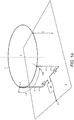
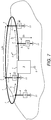
- FIG. 1a shows an antenna with a designed as a resonant structure circular loop emitter 2 for generating a circularly polarized field.
- the stretched length of the ring line of the ring line radiator 2 is chosen such that it substantially corresponds to the line wavelength.
- the ring line emitter 2 is designed to extend in a horizontal plane with the height h over the conductive base 6, so that it forms an electrical line with respect to the conductive base 6 with a characteristic impedance resulting from the height h and the effective diameter of the im Essentially results in a wire-shaped loop conductor.
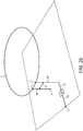
- FIG. 1b is a similar antenna according to the invention is shown in which, however, additional, the excitation 3 not belonging vertical radiators are present, which are coupled at ring line crosspoints 7 to the ring line emitter 2 and guided to the electrically conductive base 6 out and in which at points of interruption low-loss reactance circuits 13 of the Reactance X are turned on.
- the vertical radiator 4 and the switched reactance X the propagation of the line wave on the ring line radiator 2 can be brought about with preferably uniform distribution of the spacings of ⁇ / 4 between the ring line crosspoints 7.
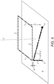
- the directional coupling conductor 8 is connected on one side via a vertical radiator 4a and a matching network 25 to the antenna terminal 5 and on the other side via a vertical radiator 4b with the conductive base 6.
- FIG. 2b In a further advantageous embodiment is in FIG. 2b to generate a continuous line wave on the ring line emitter 2, however, the excitation 3 given by two substantially vertical radiator 4, which are parallel in a respect to the 1 ⁇ 4-line wavelength distance 37 and guided via galvanic coupling points 7 to the ring line emitter 2.
- one vertical emitter 4a is connected to the antenna terminal 5 via a matching network 25 and the other vertical emitter 4b is connected to the conductive base 6 via a ground terminal 11.
- a second directional coupler 21 for generating two signals different by 90 ° is coupled to a transmission conductor 30 extending on the conductive base 6 by parallel guidance at a short distance.
- the second directional coupling conductor 21 is to feed via the vertical radiator 4 with the first directional coupling conductor 8 and the microstrip conductor 30 are connected to the antenna terminal 5.
- the electromagnetic excitation 3 takes place in such a way that equally large signals are fed between the lower ends of the vertical radiator 4 and the electrically conductive base, which are each shifted by 360 ° / 4 to each other in phase.
- the electromagnetic excitation 3 is designed as a ramp-shaped directional coupling conductor 12 with an advantageous length of substantially ⁇ / 4. This is designed substantially as a linear conductor, which advantageously extends in a plane which includes one side of the ring line radiator 2 and which is oriented perpendicular to the electrically conductive base surface 6.
- the linear conductor starting from the antenna connection 5 located on the conductive base 6, leads via a vertical feed line 4 to a coupling end spacing 16 to one of the corners of the ring line emitter 2 and is substantially below an adjacent corner from there in accordance with a ramp function led to the base 6 and connected to this via the ground terminal 11 conductive.
- the adaptation to the antenna connector 5 can be easily made.
- the particular advantage of this arrangement is the non-contact coupling of the excitation 3 to the square-shaped ring line radiator 2, which allows a particularly simple production of the antenna.
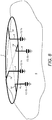
- FIG. 6 Ring line coupling points 7 formed and the electromagnetic excitation 3 is given over the same length vertical and the conductive base 6 extending radiator 4, which are each connected via an equally long lead 22 to a port of a power distribution network and this on the other hand with the antenna port. 5 connected is.
- the power distribution network consists advantageously of chain-connected, formed on the conductive base 6 ⁇ / 4-long microstrip conductors 30a, 30b, 30c, wherein their characteristic impedance - starting from a low characteristic impedance at the antenna terminal 5 - to which one of the vertical radiator 4 is directly connected via its supply line 22 - are highly stepped in such a way that the fed at the corners in the ring line emitter 2 signals have the same power and each lag 90 ° in the phase continuously lagging.
- antennas according to the invention are those arrangements in which the ring line radiator 2 of the straight length L at substantially similar distances UN to each other ring line coupling points 7 are designed and to each of which a vertical radiator 4 is coupled, which on the other hand via ground Connection points 11 are coupled to the electrically conductive base 6.
- a vertical radiator 4 is coupled, which on the other hand via ground Connection points 11 are coupled to the electrically conductive base 6.
- FIG. 7 shows an arrangement of this kind, wherein the versatile design excitation 3 is indicated in a general form.
- electromagnetic coupling that is preferably galvanic or capacitive coupling of the two antenna parts, consisting of the ring line radiator 2 and the circle group of the vertical radiator 4 at the loop coupling points 7, the antenna parts are coupled together in such a way that both antenna parts contribute constructively to a circularly polarized field.
- the ring line emitter 2 acts as a radiating element which generates a circularly polarized field with a vertical main radiation direction. This field is superimposed on the electromagnetic field generated by the vertical radiators 4.
- the electromagnetic field generated by the circle group of the vertical radiator 4 in diagonal elevation is also circularly polarized with the azimuth substantially independent main beam direction. At lower elevation, this field is vertically polarized and substantially azimuthally independent as well.
- the resonance structure is connected to the antenna connection 5 via an excitation 3 in such a way that the line wave on the ring line emitter 2 propagates substantially only in one direction of rotation so that one period of the line wave is contained in the direction of rotation of the ring structure.
- the ring structure with N vertical radiators can be divided into N segments.
- I _ 2 I _ 1 ⁇ exp j 2 ⁇ / N
- I _ S I _ 1 ⁇ exp j ⁇ - I _ 2
- ⁇ 2 ⁇ L / N ⁇ forms the phase rotation across the waveguide of length L / N for a segment.
- the vertical radiators 4 together with the reactances X form in their equivalent circuit diagram a filter consisting of a series inductance, a parallel capacitance and a further series inductance.
- the parallel capacitance is chosen by adjusting the reactances X so that the filter is adapted on both sides to the conductor impedance of the annular transmission line 1.
- the resonant structure thus consists of N conductor segments of length L / N and in each case a filter connected thereto. Each filter causes a phase rotation ⁇ .
- the electromagnetic wave which propagates in the circumferential direction along the ring structure, thus undergoes the phase rotation of 2 ⁇ in one revolution.
- the antenna is also suitable in particular for the reception of signals from low-flying satellites.
- the antenna can also be advantageously used for satellite broadcasting systems in which terrestrial, vertically polarized signals are also transmitted in support of the reception.
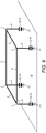
- the vertical radiator 4 as in FIG. 8 coupled via horizontal radiator elements 14 to the loop coupling points 7.
- the horizontal radiator elements 14 can be used flexibly for further shaping of the vertical radiation pattern of the antenna.
- FIG. 9 illustrated quadratic shape, with four formed at the corners of the square ring line crosspoints 7 and there galvanically connected vertical radiators 4, each with a base at the base to the ground connection point 11 introduced capacitance 15 as a reactance circuit 13.
- the excitation 3 of this resonant structure can on various types Be fashioned and is therefore in FIG. 9 not included.
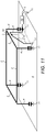
- this is non-contact as directed inductively and capacitively coupled conductor loop as a directional coupler 18 as in FIG. 11 designed.
- the directional coupling conductor 18 is tapered in shape, and is similar as in connection with the excitation 3 in FIG. 5 described, designed substantially as a linear conductor, which advantageously extends in a plane which includes one side of the ring line radiator 2 and which is oriented perpendicular to the electrically conductive base surface 6.
- the linear conductor starting from the located on the conductive base 6 ground connection points 11 via a short vertical lead and a ramp function up to a coupling distance 10 to the Ring line emitter 2 introduces, is returned from there via a vertical radiator 4 to the conductive base and connected via a matching network 25 to the antenna terminal 5.
- one of the vertical radiators 4a with the reactance circuit 13 realized as a capacitor 15 is not coupled to the ground connection point 11 on the electrically conductive base 6 but to the connection formed on the plane of the conductive base 6 to the matching network 25 and thus to the antenna connection 5 ,
- the design of the characteristic impedance can be carried out in a known manner, for example by selecting the effective diameter of the substantially linear ring line emitter 2, or as exemplified by an additional conductor 19 reducing the characteristic impedance.
- To further support the unidirectionality of the wave propagation on the loop emitter 2 is in FIG. 12b a further portion of the ring line radiator 2 opposite the first section having a different characteristic impedance with characteristic impedance deviating from the characteristic impedance of the remaining sections of the ring line radiator 2.
- the electromagnetic excitation 3 is designed by partial coupling to one of the vertical radiator 4 at one of the loop coupling points 7a.
- the unidirectional effect of the electromagnetic excitation 3 with respect to the wave propagation is achieved by partial coupling to a vertical radiator 4a via a, to a part of the ring line radiator 2 in parallel
- Coupling conductor 23 given and the other end of the coupling conductor 23 is connected to a vertical and the conductive base 6 extending radiator 4e, the latter being connected via a matching network 25 to the antenna terminal 5.
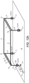
- FIG. 14 is the matching network 25 in the form of a parallel to the electrically conductive base 6 set high-impedance transmission line over about 1 ⁇ 4 of the wavelength advantageously carried out.
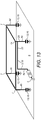
- each section between adjacent ring line coupling points 7 of the ring line radiator 2 can be given a meandering shape 17 that is the same for all sections, as shown by way of example in FIG FIG. 10 is shown.
- An essential feature of an antenna according to the present invention is the possibility for particularly low-cost production.
- an outstandingly advantageous form of the antenna with square ring-shaped radiator 2 is similar in nature to that in FIG. 12b designed and in FIG. 15 shown.
- the ring line emitter 2 with the vertical emitters 4a, 4b, 4c, 4d, together with the flat-shaped capacitance electrodes 32a, 32b, 32c, 32d individually shaped at their lower end, can be made, for example, from a coherent, stamped and formed sheet metal part.
- the characteristic impedance of the sections of the ring line radiator 2 can be designed individually by choosing the width of the connectors.
- the electrically conductive base 6 is preferably designed as a conductive coated circuit board.
- the reactance circuits 13 realized as capacitances 15 are formed in such a way that the capacitance electrodes 32a, 32b, 32c, 32d are provided by interposing a dielectric plate 33 located between them and the electrically conductive base 6 for coupling three vertical radiators 4a, 4b, 4c the electrically conductive base 6 are designed.
- this is one of the conductive layer of the circuit board insulated, flat counter electrode 34 designed. In a particularly low-effort manner, it is therefore possible to produce the essential dimensions necessary for the function of the antenna via a stamped and formed sheet-metal part with the advantages of high reproducibility.
- the sheet-metal part, the dielectric plate 33 and the electrically conductive base 6 embodied as a printed circuit board can be connected to one another by way of example by low-cost adhesive bonding and thus without costly soldering.
- the connection to a receiver can be realized in a known manner, for example by connecting a microstrip line or a coaxial line, starting from the antenna connection 5.
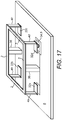
- FIG. 16 instead of a dielectric plate 33 between the lower ends of the vertical radiators 4a, 4b, 4c, 4d and the electrically conductive base 6 designed as a conductive coated printed circuit board, a further conductive coated, dielectric circuit board is inserted.
- the capacitive coupling of the fourth vertical radiator 4 d to the antenna terminal 5, which is designed as a planar counterelectrode 34 isolated from the conductive layer, is provided via the capacitance electrode 32.
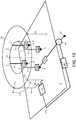
- the antenna is in FIG. 17 similar in the Figures 16 designed, wherein the conductive structure, consisting of the ring conductor 2 and the associated vertical radiators 4, is fixed by a dielectric support structure 36 in such a way that the dielectric plate 33 is realized in the form of an air gap.
- the reactance circuit 13 is designed in such a way multi-frequency, that both the resonance of the ring line radiator 2 and the required running direction of the line shaft on the ring line radiator 2 in separate frequency bands is given.
- This cavity 38 is thus an effective part of the conductive base 6 and consists of a cavity base surface 39 in a base surface plane E2 located at a distance h1 parallel to and below the surface plane E1.
- the cavity base surface 39 is connected to the planar part of the conductive base 6 via the cavity side surfaces 40.
- the ring line emitter 2 is introduced into the cavity 38 in a further horizontal ring line plane E at the height h extending above the cavity base surface 39.
- the environment of the ring line radiator 2 with the cavity basically has a narrowing the frequency bandwidth of the antenna 1 effect, which is essentially determined by the cavity spacing 41 between the ring line radiator 2 and the cavity 38. Therefore, the conductive cavity base surface 39 should be at least large enough to at least cover the vertical projection surface of the loop emitter 2 to the base surface plane E2 located below the conductive base. In an advantageous embodiment, however, the cavity base surface 39 is larger and selected in such a way that the cavity side surfaces 40 can be designed as vertical surfaces and while a sufficient cavity spacing 41 between the ring line radiator 2 and the cavity 38 is given.
- the base surface plane E2 is chosen to be approximately as large as the vertical projection surface of the ring line radiator 2 to the base surface plane E2 and make the cavity side surfaces 40 along a contour inclined from a vertical line.
- the inclination of this contour is to be selected in such a way that, given the required frequency bandwidth of the antenna 1, a sufficiently large cavity spacing 41 is present between the ring line emitter 2 and the cavity 38 at each location.
- the inclination of the cavity side surfaces 40 is selected in each case in the manner that at a vertical distance z above the cavity base surface 39, the horizontal distance d between the vertical connecting line between the ring tube radiator 2 and the cavity base surface 39 and the nearest cavity side surface 40 assumes at least half the vertical distance z.
- the frequency bandwidth of the antenna 1 increases the further the cavity 38 is opened upwards. If, while maintaining the last-mentioned necessary cavity spacing 41 between the ring line radiator 2 and the cavity 38, the cavity side surfaces 40 are designed vertically, the necessary frequency bandwidth is also ensured. The same also applies if the height h of the ring line plane E is greater than the depth of the cavity base surface 39, as shown in FIG FIG. 18a is shown. That is, h is larger than h1 and the antenna 1 is not fully integrated with the vehicle body.
- ring line emitters 2 offer the advantage of a particularly space-saving design.
- a plurality of ring line radiators for the different frequencies of several radio services can be designed around a common center Z. Due to their different resonant frequencies, the different ring line radiators influence only slightly, so that small distances between the ring lines of the ring radiators 2 can be designed.
- a circular-polarized ring-type radiator with an azimuthal circular diagram the phase of the radiated far-field electromagnetic field rotates with the azimuthal angle of the propagation vector due to the current wave propagating in a running direction on the loop.
- Fig. 19 is a ring line emitter 2 according to the invention surrounded by another ring line emitter 2a, which is formed according to the rules described above and which also forms a resonant structure and is electrically excited in such a way that on the loop the current distribution of a current line wave in a single Adjusting the direction of rotation, the phase difference is in contrast to the inner loop emitter 2 over a circuit straight N * 2 ⁇ .
- N is an integer and is N> 1.
- the two ring line radiators are combined with the same center Z.
- the phase reference points of the two ring line emitters 2, 2a are congruent in the common center Z.
- a directional antenna with a predetermined azimuthal main direction and elevation can be designed according to the invention. This is done by the different azimuthal dependency of the current phases on the two ring line radiators 2, 2a, depending on the phase position of the two current waves on the ring line radiators 2, 2a, the radiation depending on the azimuth angle of the propagation vector partially superimposed supportive or attenuating.
- the further ring line radiator 2a as a rotationally symmetrical about the center Z arranged polygonal or circular closed ring line radiator 2a in a horizontal plane with the height ha on the conductive base 6 extending designed.
- the ring line 2a is fed in such a way that adjusts itself to the current distribution of a current line wave whose phase difference over a cycle is just 2 * 2 ⁇ .
- vertical radiator 4a can also be here the extended length of another ring line radiator 2a shorter by a shortening factor k ⁇ 1 than the corresponding double wavelength ⁇ .
- the phase difference of 2 ⁇ (ring line radiator 2) and 2 * 2 ⁇ (ring line radiator 2a) on the loop by increasing the line inductance and / or the line capacitance to the conductive base 6 done.
- this circular or polygonal shape is designed with 8 equidistantly arranged cross-coupling points 7a with vertical radiators 4 coupled thereto.
- Fig. 20 shows by way of example a circular ring line radiator 2a with further reactance circuits 45a,... 45d, which are introduced into the vertical radiators 4.
- reactance circuits 45a ... 45d together with the characteristic impedances Zf of the ring line sections between the loop coupling points 7a are matched to each other so that both the running direction of the rotating shaft in the predetermined direction and the resonance of the ring conditioner 2a for the phase condition Set 2 * 2 ⁇ for this wave.
- the ring line sections of the two ring line emitters 2, 2a can be selected substantially shorter than a quarter wavelength up to ⁇ / 8. Accordingly, in successive loop sections, large and small inductance values and small and large capacitance values of the loop sections alternate.
- FIG. 21 shows a plan view of the directional antenna in FIG. 20 , wherein the antenna is formed of a square shaped ring line radiator 2 and an octagonal shaped further ring line radiator 2.
- the loop coupling points 7 and 7a are respectively formed at the corners of the square inner ring and the octagonal outer ring.
- To each of the vertical radiator 4 are connected.
- the summation network 44 as summation and selection network 44a, it is possible to select separately there between the received signals of the two ring line emitters 2, 2a and the weighted superimposition-possibly with different weightings.
Landscapes
- Variable-Direction Aerials And Aerial Arrays (AREA)
- Waveguide Aerials (AREA)
Description
Die Erfindung betrifft eine Antenne für den Empfang zirkular polarisierter Satellitenfunksignale nach dem Oberbegriff des Anspruchs 1 (vgl.
Insbesondere bei Satelliten-Rundfunksystemen kommt es besonders auf die Wirtschaftlichkeit sowohl bezüglich der vom Satelliten abgestrahlten Sendeleistung als auch auf die Effizienz der Empfangsantenne an. Satellitenfunksignale werden aufgrund von Polarisationsdrehungen auf dem Übertragungsweg in der Regel mit zirkular polarisierten elektromagnetischen Wellen übertragen. Vielfach werden Programminhalte zum Beispiel in frequenzmäßig dicht nebeneinander liegenden getrennten Frequenzbändern übertragen. Dies geschieht im Beispiel des SDARS-Satellitenrundfunks bei einer Frequenz von circa 2,33 GHz in zwei benachbarten Frequenzbändern jeweils mit einer Bandbreite von 4 MHz mit einem Abstand der Mittenfrequenzen von 8 MHz. Die Signale werden von unterschiedlichen Satelliten mit einer in einer Richtung zirkular polarisierten elektromagnetischen Welle abgestrahlt. Demzufolge werden zum Empfang in der entsprechenden Drehrichtung zirkular polarisierte Antennen verwendet. Solche Antennen sind zum Beispiel aus
Die aus der
Beide Antennenformen sind zwar für den Empfang von Satellitensignalen geeignet, welche von hoch fliegenden Satelliten - so genannten HEOS - abgestrahlt werden. Durch eine Erhöhung der Kreuzpolarisationsunterdrückung in einem möglichst großen Elevationswinkelbereich kann jedoch der Empfang von Temperaturrauschen im Vergleich zu dem Empfang der Satellitensignale deutlich reduziert werden.Although both antenna types are suitable for the reception of satellite signals, which are emitted by high-flying satellites - so-called HEOS. However, by increasing the cross-polarization suppression in the largest possible elevation angle range, the reception of temperature noise can be significantly reduced compared to the reception of the satellite signals.
Hinzu kommt die Schwierigkeit der Gestaltung von Antennen mit kleinerem Bauvolumen, welches insbesondere für mobile Anwendungen zwingend gefordert ist. Als weitere Antennen dieser Art sind nach dem Stand der Technik Patch-Antennen bekannt, welche jedoch bezüglich des Empfangs unter niedrigem Elevationswinkel ebenfalls weniger leistungsfähig sind und aufgrund der Verwendung dielektrischer Materialien Verluste aufweisen, welche das Signal-zu-Rauschverhältnis deutlich beeinträchtigen.Added to this is the difficulty of designing antennas with a smaller volume, which is imperative especially for mobile applications. As other antennas of this type are known in the prior art patch antennas, which are also less efficient with respect to the reception at low elevation angle and due to the use of dielectric materials have losses that significantly affect the signal-to-noise ratio.
Für den Empfang aller genannten Funkdienste ist jedoch aufgrund der in Großserie hergestellten Antennen die Wirtschaftlichkeit bei der Herstellung von ausschlaggebender Bedeutung.For the reception of all mentioned radio services, however, the economy in the production of essential because of the manufactured in mass production antennas of crucial importance.
Aus der
Aus der
Aus der
Für die Herstellung von Antennen, welche aus der
Aufgabe der Erfindung ist es deshalb, eine Antenne mit geringem Bauvolumen anzugeben, welche je nach ihrer Auslegung sowohl für einen besonders leistungsstarken Empfang von unter hohen Elevationswinkeln einfallenden zirkular in einer Drehrichtung polarisiert ausgestrahlten Satellitensignalen mit hohem Gewinn in vertikaler Richtung als auch für den leistungsstarken Empfang von unter niedrigen Elevationswinkeln einfallenden zirkular in einer Drehrichtung polarisiert ausgestrahlten Satellitensignalen mit hoher Kreuzpolarisationsunterdrückung über einen großen Elevationswinkelbereich geeignet ist, wobei insbesondere auch die Möglichkeit zu einer wirtschaftlichen Herstellung gegeben sein soll.The object of the invention is therefore to provide an antenna with low volume, which depending on their design for both a particularly powerful reception of high elevation angles incident circularly polarized in one direction radiated satellite signals with high gain in the vertical direction and for the high-performance reception of At low elevation angles incident circularly polarized in one direction of rotation emitted satellite signals with high cross polarization suppression over a large elevation angle range is suitable, in particular, the possibility should be given to an economical production.
Diese Aufgabe wird bei einer Antenne nach dem Oberbegriff des Hauptanspruchs durch die kennzeichnenden Merkmale des Hauptanspruchs gelöst.This object is achieved in an antenna according to the preamble of the main claim by the characterizing features of the main claim.
Mit einer Antenne nach der Erfindung ist der Vorteil verbunden, auch den Empfang linear vertikal polarisierter und unter niedriger Elevation empfangener Wellen mit azimutal nahezu homogenem Richtdiagramm zu ermöglichen. Ein weiterer Vorteil einer Antenne nach der Erfindung ist ihre besonders einfache Herstellbarkeit, welche die Realisierung auch durch einfache gebogene Blechstrukturen ermöglicht.With an antenna according to the invention, the advantage is associated with allowing the reception of linearly polarized waves received at low elevation with azimuthally nearly homogeneous directional diagram. Another advantage of an antenna according to the invention is its particularly simple manufacturability, which allows the realization by simple curved sheet metal structures.
Vorteilhafte Ausführungsformen sind in der Beschreibung un den Unteransprüchen beschrieben.Advantageous embodiments are described in the description and the dependent claims.
Gemäß der Erfindung umfasst die Antenne für den Empfang zirkular polarisierter Satellitenfunksignale wenigstens eine im Wesentlichen horizontal orientierte über einer leitenden Grundfläche 6 angeordnete Leiterschleife, mit einer mit einem Antennenanschluss 5 verbundenen Anordnung zur elektromagnetischen Erregung 3 der Leiterschleife. Die Leiterschleife ist als Ringleitungsstrahler 2 durch eine polygonale oder kreisförmige geschlossene Ringleitung in einer horizontalen Ebene mit der Höhe h über der leitenden Grundfläche 6 verlaufend gestaltet. Der Ringleitungsstrahler 2 bildet eine Resonanzstruktur und ist durch die elektromagnetische Erregung 3 in der Weise elektrisch erregbar, dass sich auf der Ringleitung die Stromverteilung einer laufenden Leitungswelle in einer Umlaufrichtung einstellt, deren Phasenunterschied über einen Umlauf gerade 2π beträgt. Zur Unterstützung der vertikal orientierten Anteile des elektromagnetischen Feldes sind mindestens zwei weitere am Ringleitungsstrahler 2 vertikale und zur leitenden Grundfläche hin verlaufende Strahler 4 vorhanden, welche sowohl mit dem Ringleitungsstrahler 2 als auch der elektrisch leitenden Grundfläche 6 elektromagnetisch verkoppelt sind. Zur Erzeugung einer reinen Leitungswelle ist die Höhe h vorzugsweise kleiner als 1/5 der Freiraum-Wellenlänge λ zu wählen.According to the invention, the antenna for receiving circularly polarized satellite radio signals comprises at least one substantially horizontally oriented conductor loop arranged above a
Die bei Antennen nach der vorliegenden Erfindung geforderten Fertigungstoleranzen können in vorteilhafter Weise wesentlich leichter eingehalten werden. Ein weiterer sehr wesentlicher Vorteil der vorliegenden Erfindung ergibt sich aus der Eigenschaft, dass neben der horizontal polarisierten Schleifenantenne 14 mindestens an einem Ringleitungs-koppelpunkt 7 ein weiterer Strahler 4 vorhanden ist, welcher eine senkrecht zur Polarisation der Schleifenantenne 14 orientierte Polarisation aufweist. Dieser Strahler kann bei Vorhandensein terrestrisch vertikal polarisiert ausgestrahlter Signale vorteilhaft auch zum Empfang dieser Signale eingesetzt werden.The required in antennas according to the present invention manufacturing tolerances can be maintained in an advantageous manner much easier. Another very important advantage of the present invention results from the property that, in addition to the horizontally polarized
Die Erfindung wird im Folgenden an Hand von Ausführungsbeispielen näher erläutert. Die zugehörigen Figuren zeigen im Einzelnen:
-
Fig. 1 :- a) Antenne mit einem als Resonanzstruktur gestalteten
kreisförmigen Ringleitungsstrahler 2 zur Erzeugung eines zirkular polarisierten Feldes mit azimutal abhängiger Phase mit einerelektromagnetischen Erregung 3, welche durch Einspeisung an λ/4 voneinander entfernten Ringleitungs-koppelpunkten 7 von um 90° in der Phase unterschiedlichen Signalen zur Erzeugung einer umlaufenden Welle von einer Wellenlänge über den Umfang der Leitung gegeben ist. Die Unterstützung vertikaler Komponenten des elektrischen Strahlungsfeldes erfolgt durch dievertikalen Strahler 4. - b) wie in a) jedoch mit zusätzlichen
vertikalen Strahlern 4, welche jeweils an einerUnterbrechungsstelle 23 mit einerverlustarmen Blindwiderstandsschaltung 13 der Reaktanz X beschaltet sind.
- a) Antenne mit einem als Resonanzstruktur gestalteten
-
Fig. 2 :- a) Antenne wie in
Figur 1 , jedoch zur Erzeugung der fortlaufenden Leitungswelle mit einem in günstigem Abstand - bezüglich des Leitungs-Wellenwiderstands - parallel zumRingleitungsstrahler 7c geführten λ/4-Richtkoppelleiters 8. - b) Antenne wie in Figur a) mit jedoch zwei im Wesentlichen
vertikalen Strahlern 4, welche in einem bezüglich der ¼-Leitungs-Wellenlängekleinen Abstand 37 parallel geführt sind.
- a) Antenne wie in
-
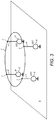
Fig. 3 :Ringleitungsstrahler 2 jedoch mit einerelektromagnetischen Erregung 3 an vier jeweils um λ/4 längs der Ringleitung versetzten Ringleitungs-Koppelpunkten 7 durch in der Phase jeweils um 90° versetzten Signalen der Speisequellen. Die Speisequellen derErregung 3 können auf an sich bekannte Weise durch Leistungsteilung und 90°-Hybridkoppler gewonnen werden. -
Fig. 4 : Antenne wie inFigur 2zweiten Richtkoppelleiter 21beinhaltenden Erregung 3. Der zweite λ/4-Richtkoppelleiter 8 ist parallel zu einemMikrostreifenleiter 30 geführt und bildet zusammen mit dem an denRingleitungsstrahler 2 angekoppelten λ/4-Richtkoppelleiter 8 den zweiten λ/4-Richtkoppler. -
Fig. 5 : Antenne mit einem als geschlossenen quadratischen Leitungsring mit der Kantenlänge von λ/4gestalteten Ringleitungsstrahler 2. DieErregung 3 ist als berührungslose Ankopplung an denRingleitungsstrahler 2 über die rampenförmige λ/4-richtwirkende Koppelstruktur 18 mit demAntennenanschluss 5 gestaltet. Die Koppelstruktur 18 beinhaltet denvertikalen Strahler 4 -
Fig. 6 : Antenne mit λ/4 voneinander entfernten Ringleitungs-Koppelpunkten 7, wobei dieelektromagnetische Erregung 3 über gleich langevertikale Strahler 4 über den Anschluss an einen Leistungs-Verteilnetzwerk - bestehend aus in Kette geschalteten, auf derleitenden Grundfläche 6 gebildeten λ/4-langen Mikrostreifenleitern -
Fig. 7 : Antenne, beispielhaft mitkreisförmigem Ringleitungsstrahler 2 mit allgemeinangedeuteter Erregung 3 und mit am Umfang äquidistant angeordneten Ringleitungs-Koppelpunkten 7 mit daran angekoppeltenvertikalen Strahlern 4, in welche an Unterbrechungsstellenverlustarme Blindwiderstandsschaltungen 13 mit den für die Erzeugung einer umlaufenden Stromwelle auf demRingleitungsstrahler 2 notwendigen unterschiedlichen Reaktanzen X eingeschaltet sind. -
Fig. 8 : Antenne wie inFigur 7 -
Fig. 9 : Antenne mit einer besonders vorteilhaften Ausführungsform desRingleitungsstrahlers 2 in quadratischer Form mit vier an den Ecken befindlichenvertikalen Strahlern 4. Die auf unterschiedliche Weisegestaltete Erregung 3 ist nicht gezeichnet. -
Fig. 10 : Antenne wie inFigur 9 , wobei jedoch jeder Abschnitt zwischen benachbarten Ringleitungs-Koppelpunkten 7 desRingleitungsstrahlers 2 zur Verkleinerung der Resonanzstruktur eine für alle Abschnitte gleichemäanderförmige Ausformung 17 enthält. -
Fig. 11 : Antenne wie inFigur 9 , mitelektromagnetischer Erregung 3 in Form einer gerichtet induktiv und kapazitiv angekoppelten Leiterschleife als Richtkoppler 18 in getaperter Form und einemNetzwerk 25 zur Leistungsanpassung. -
Fig. 12 :- a) Antenne nach der Erfindung wie in
Figur 9 mitelektromagnetischer Erregung 3 durch Einspeisung am unteren Ende an einem dervertikalen Strahler 4 über die als Kapazität 15gestaltete Blindwiderstandsschaltung 13. Zur Unterstützung der Unidirektionalität der Wellenausbreitung auf demRingleitungsstrahler 2 ist durch Gestaltung des Wellenwiderstands des Teilstücks desRingleitungsstrahlers 2 zum benachbarten Ringleitungs-Koppelpunkt 7b in Abweichung von dem Wellenwiderstand der übrigen Teilstücke desRingleitungsstrahlers 2 gestaltet. - b) wie in Figur a) jedoch mit zwei einander gegenüberliegenden Teilstücken des
Ringleitungsstrahlers 2, deren Wellenwiderstand von dem der beiden übrigen Teilstücke abweichen.
- a) Antenne nach der Erfindung wie in
-
Fig. 13 : Antenne nach der Erfindung wie inFigur 9 . Die unidirektionale Wirkung der elektromagnetischen Erregung 3 ist durch Teilankopplung eines über einen Teil des Ringleitungsstrahlers 2 parallel zu diesem geführten Koppelleiter 23 an einen der vertikalenStrahler 4 gegeben. Das andere Ende desKoppelleiters 23 ist über einen vertikalenStrahler 4 mit daran angeschlossenem Anpassnetzwerk 25mit dem Antennenanschluss 5 verbunden. -
Fig. 14 : Antenne nach der Erfindung wie inFigur 13wobei das Anpassnetzwerk 25 in Form einer parallel zur elektrisch leitenden Grundfläche 6 gelegten hochohmigen Übertragungsleitung über etwa ¼ der Wellenlänge ausgeführt ist. -
Fig. 15 : Antenne nach der Erfindung wie inFiguren 12a und12b . Die Kapazitäten 15 sind in der Weise gebildet, dass die vertikalenStrahler 4 an ihrem unteren Ende zu individuell gestalteten flächigen Kapazitätselektroden 32a, 32b, 32c, 32d ausgeformt sind. Durch Zwischenlage zwischen diesen und der als elektrisch leitend beschichteten Leiterplatte ausgeführten elektrisch leitenden Grundfläche 6 befindlichen dielektrischen Platte 33 sind die Kapazitäten 15 zur Ankopplung von drei vertikalen Strahlern 4a, 4b, 4c an die elektrisch leitende Grundfläche 6 gestaltet. Zur kapazitiven Ankopplung des vierten vertikalen Strahlers 4d, anden Antennenanschluss 5 ist dieser als eine von der leitenden Schicht isolierte, flächige Gegenelektrode 34 gestaltet. -
Fig. 16 : Antenne nach der Erfindung wie inFiguren 12a und12b . Zwischen den unteren Enden der vertikalenStrahler Strahler Strahler 4 an die elektrisch leitende Grundfläche 6 verbunden. Für die kapazitive Ankopplung des vierten vertikalen Strahlers 4d anden Antennenanschluss 5 ist dieser als eine von der leitenden Schicht isolierte, flächige Gegenelektrode 34 gestaltet. -
Fig. 17 : Antenne nach der Erfindung wie inFiguren 15 und16 , wobei die leitende Struktur, bestehend ausdem Ringleiter 2 und den damit verbundenen vertikalen Strahlern 4 durch eine dielektrische Stützstruktur 36 so fixiert ist, dass die dielektrische Platte 33 in Form eines Luftspaltes realisiert ist. -
Fig. 18 : Profilansicht eines Ringleitungsstrahlers 2 in einer sich nach oben öffnenden Kavität 38, welche z. B. zum Zwecke der Integration in eine Fahrzeugkarosserie durch Ausformung der leitenden Grundebene 6 gestaltet ist. Die Höhe h1 bezeichnet die Tiefe der Kavität und die Höhe h denAbstand des Ringleitungsstrahlers 2 über der Kavitäts-Basisfläche 39. Ein zu geringer Abstand 41 zwischen dem Ringleitungs-strahler 2 und den Kavitäts-Seitenflächen 40 hat eine die Frequenzbandbreite der Antenne 1 einengende Wirkung.- a) h > h1: teilweise Integration
- b) h = h1: vollständige Integration
-
Fig. 19 :Ringleitungsstrahler 2 nach der Erfindung kombiniert mit einem weiteren Ringleitungsstrahler 2a mit gleichem Zentrum Z und einem Phasenunterschied der auf der Ringleitung 2a in einer einzigen Umlaufrichtung sich ausbreitenden Leitungswelle über einen Umlauf von gerade N*2π mit (N>2) zur Bildung einer Richtantenne mit einem Richtdiagramm mit azimutaler Hauptrichtung am Richtantennen-Anschluss 43. -
Fig. 20 : Richtantenne wie inFigur 19mit kreisförmigem Ringleitungsstrahler 2 und weiterem Ringleitungsstrahler 2a mit N=2.Die vertikalen Strahler 13a-d und 45a-h sind auf beiden Ringleitungsstrahlern äquidistant und entsprechend einer Phasen-Differenz der laufenden Welle von jeweils π/2 angeordnet. DieEmpfangssignale am Antennenanschluss 5 und an der Strahler-Anschlussstelle 46 werden überein steuerbares Phasendrehglied 42 im Summations- und Auswahl-Netzwerk 44 zur Bildung des Richtdiagramms mit steuerbarer azimutaler Hauptrichtung überlagert. -
Fig. 21 : Richtantenne wie inFigur 20 -
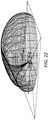
Fig. 22 : Räumliches Richtdiagramm der Richtantenne inFigur 21
-
Fig. 1 :- a) antenna having a designed as a resonant structure
circular ring radiator 2 for generating a circularly polarized field with azimuthally dependent phase with anelectromagnetic excitation 3, which by feeding at λ / 4 remote loop coupling points of 7 by 90 ° in the phase different signals to Generation of a rotating wave of a wavelength over the circumference of the line is given. The support of vertical components of the electric radiation field is carried out by the vertical radiator. 4 - b) as in a) but with additional
vertical radiators 4, which are each connected at aninterruption point 23 with a low-loss reactance circuit 13 of the reactance X.
- a) antenna having a designed as a resonant structure
-
Fig. 2 :- a) Antenna as in
FIG. 1 , However, for generating the continuous line wave with a at a favorable distance - with respect to the line characteristic impedance - parallel to thering line radiator 7c out guided λ / 4 Richtkoppelleiters. 8 - b) Antenna as in Figure a) but with two substantially
vertical radiators 4, which are guided in parallel with respect to the ¼-line wavelength distance 37.
- a) Antenna as in
-
Fig. 3 :Ring line emitter 2, however, with anelectromagnetic excitation 3 to four each by λ / 4 along the ring line offsetloop line crosspoints 7 by in each case by 90 ° offset signals of the supply sources. The feed sources of theexcitation 3 can be obtained in a manner known per se by power sharing and 90 ° hybrid coupler. -
Fig. 4 : Antenna as inFIG. 2 , but with a seconddirectional coupler 21 containingexcitation 3. The second λ / 4Richtkoppelleiter 8 is guided parallel to amicrostrip conductor 30 and forms together with the coupled to the ring line emitter λ / 4Richtkoppelleiter 8 the second λ / 4-directional coupler , -
Fig. 5 Antenna with aring line radiator 2 designed as a closed square line ring with the edge length of λ / 4. Theexcitation 3 is designed as a non-contact coupling to thering line radiator 2 via the ramp-shaped λ / 4-directional coupling structure 18 with theantenna connection 5. The coupling structure 18 includes thevertical radiator 4 -
Fig. 6 : Antenna with λ / 4 distantring line crosspoints 7, wherein theelectromagnetic excitation 3 via equally longvertical radiator 4 via the connection to a power distribution network - consisting of connected in chain, formed on theconductive base 6 λ / 4-long Microstrip conductors -
Fig. 7 : Antenna, by way of example with circularring line emitter 2 with generally indicatedexcitation 3 and with circumferentially equidistantly arrangedring line crosspoints 7 withvertical emitters 4 coupled thereto, into which at interruption points low-impedance reactance circuits 13 with those necessary for the generation of a circulating current wave on thering line emitter 2 different reactances X are turned on. -
Fig. 8 : Antenna as inFIG. 7 , but with horizontal additional elements for further shaping of the directional diagram. -
Fig. 9 : Antenna with a particularly advantageous embodiment of thering line radiator 2 in square shape with four vertical radiators located at thecorners 4. Theexcitation 3 designed in different ways is not drawn. -
Fig. 10 : Antenna as inFIG. 9 , wherein, however, each section between adjacent ringline coupling points 7 of thering line radiator 2 for reducing the resonance structure contains a meander-shapedformation 17 which is the same for all sections. -
Fig. 11 : Antenna as inFIG. 9 , withelectromagnetic excitation 3 in the form of a directionally inductively and capacitively coupled conductor loop as a directional coupler 18 in capped form and anetwork 25 for power adjustment. -
Fig. 12 :- a) Antenna according to the invention as in
FIG. 9 withelectromagnetic excitation 3 by feeding the lower end of one of thevertical radiator 4 via the designed as a capacitance 15reactance circuit 13. To support the unidirectional wave propagation on thering line radiator 2 is by shaping the characteristic impedance of the section of thering line radiator 2 to the adjacentloop cross-coupling point 7b designed in deviation from the characteristic impedance of the remaining sections of thering line radiator 2. - b) as in Figure a) but with two opposing sections of the
ring line radiator 2, whose characteristic impedance differ from that of the other two sections.
- a) Antenna according to the invention as in
-
Fig. 13 : Antenna according to the invention as inFIG. 9 , The unidirectional effect of theelectromagnetic excitation 3 is given by partial coupling of a part of thering line emitter 2 parallel to this guidedcoupling conductor 23 to one of thevertical radiator 4. The other end of thecoupling conductor 23 is connected to theantenna connection 5 via avertical radiator 4 with amatching network 25 connected thereto. -
Fig. 14 : Antenna according to the invention as inFIG. 13 , wherein thematching network 25 in the form of a parallel to the electricallyconductive base surface 6 high-impedance transmission line is performed over about ¼ of the wavelength. -
Fig. 15 : Antenna according to the invention as inFIGS. 12a and12b , The capacitances 15 are formed in such a way that thevertical radiators 4 are formed at their lower end to form individualizedarea capacitance electrodes conductive base plate 6 located dielectric plate 33 are the capacitances 15 for coupling threevertical radiators conductive base 6 designed. For the capacitive coupling of the fourthvertical radiator 4d, to theantenna connection 5, this is designed as a flat counterelectrode 34 isolated from the conductive layer. -
Fig. 16 : Antenna according to the invention as inFIGS. 12a and12b , Between the lower ends of thevertical radiators conductive base 6, a further conductive coated dielectric circuit board is inserted. The lower ends of thevertical radiators surface capacitive electrodes vertical radiators 4 to the electrical onesconductive base 6 connected. For the capacitive coupling of the fourthvertical radiator 4d to theantenna terminal 5, this is designed as a flat counterelectrode 34 isolated from the conductive layer. -
Fig. 17 : Antenna according to the invention as inFIGS. 15 and16 wherein the conductive structure consisting of thering conductor 2 and the associatedvertical radiators 4 is fixed by adielectric support structure 36 so that the dielectric plate 33 is realized in the form of an air gap. -
Fig. 18 : Profile view of aring line radiator 2 in an upwardly openingcavity 38, which z. B. for the purpose of integration in a vehicle body by forming the conductive ground plane. 6 is designed. The height h1 denotes the depth of the cavity and the height h the distance of thering line radiator 2 above the cavity base surface 39. Too small adistance 41 between thering line radiator 2 and the cavity side surfaces 40 has a narrowing the frequency bandwidth of the antenna 1 effect ,- a) h> h1: partial integration
- b) h = h1: complete integration
-
Fig. 19 :Ring line emitter 2 according to the invention combined with anotherring line emitter 2a with the same center Z and a phase difference of on thering line 2a in a single direction propagating line wave over a cycle of just N * 2π with (N> 2) to form a directional antenna with a directional diagram with azimuthal main direction at the directional antenna port 43rd -
Fig. 20 : Directional antenna as inFIG. 19 with circularring line emitter 2 and furtherring line emitter 2a with N = 2. Thevertical radiators 13a-d and 45a-h are arranged equidistantly on both ring line radiators and corresponding to a phase difference of the current wave of π / 2 in each case. The received signals at theantenna connection 5 and at theradiator connection point 46 are superimposed via a controllablephase rotation element 42 in the summation andselection network 44 to form the directional diagram with a controllable azimuthal main direction. -
Fig. 21 : Directional antenna as inFIG. 20 however, with a square-shaped ring line radiator 2 (phase difference of the traveling wave of 2π distributed over the circumference) and with an octagonal shaped furtherring line radiator 2a (phase difference of the traveling wave of 4π distributed over the circumference). -
Fig. 22 : Spatial directional diagram of the directional antenna inFIG. 21 with pronounced azimuthal main direction (arrow) and zero.
Der Ringleitungsstrahler 2 der Erfindung ist als eine passive Resonanzstruktur für eine Sende- oder Empfangsantenne gestaltet, welche die Abstrahlung bzw. den Empfang von im Wesentlichen zirkular polarisierten Wellen in einem Elevationswinkelbereich zwischen theta=0° (vertikal) und theta=65° und im Wesentlichen vertikal polarisierter Wellen in einem Elevationswinkelbereich zwischen theta = 90° und theta = 85° ermöglicht, wobei theta den Winkel der einfallenden Welle gegenüber der Vertikalen beschreibt. Azimutal wird dabei im allgemeinen Rundstrahlung angestrebt.The
Die Verteilung der Ströme auf einer Antenne im Empfangsbetrieb ist vom Abschlusswiderstand an der Antennenanschlussstelle abhängig. Im Gegensatz hierzu ist im Sendebetrieb die auf den Speisestrom an der Antennenanschlussstelle bezogene Verteilung der Ströme auf den Antennenleitern vom Quellwiderstand der speisenden Signalquelle unabhängig und ist somit eindeutig mit dem Richtdiagramm und der Polarisation der Antenne verknüpft. Aufgrund dieser Eindeutigkeit in Verbindung mit dem Gesetz der Reziprozität, nach welchem die Strahlungseigenschaften - wie Richtdiagramm und Polarisation - im Sendebetrieb wie im Empfangsbetrieb identisch sind, wird die erfindungsgemäße Aufgabe bezüglich Polarisation und Strahlungsdiagramme an Hand der Gestaltung der Antennenstruktur zur Erzeugung entsprechender Ströme im Sendebetrieb der Antenne gelöst. Damit ist auch die erfindungsgemäße Aufgabe für den Empfangsbetrieb gelöst. Alle im Folgenden durchgeführten Betrachtungen über Ströme auf der Antennenstruktur und deren Phasen beziehungsweise deren Phasenbezugspunkt beziehen sich somit auf den reziproken Betrieb der Empfangsantenne als Sendeantenne, wenn nicht ausdrücklich der Empfangsbetrieb angesprochen ist.The distribution of the currents on an antenna in receive mode depends on the terminator at the antenna junction. In contrast, in the transmission mode, the distribution of the currents on the antenna conductors relative to the supply current at the antenna connection point is independent of the source resistance of the supplying signal source and is thus clearly linked to the directional diagram and the polarization of the antenna. Because of this uniqueness in connection with the law of reciprocity, according to which the radiation properties - such as directional diagram and polarization - are identical in the transmission mode as in the receiving mode, the object of the invention with respect to polarization and radiation patterns on the basis of the design of the antenna structure for generating corresponding currents in the transmission mode of Antenna solved. Thus, the object of the invention for the receiving operation is solved. All considerations made below about currents on the antenna structure and their phases or their phase reference point thus refer to the reciprocal operation of the receiving antenna as a transmitting antenna, unless the receiving mode is specifically addressed.
In
In einer weiteren Ausgestaltung erfolgt die Erzeugung einer fortlaufenden Leitungswelle auf dem Ringleitungsstrahler 2 in
In einer weiteren vorteilhaften Ausgestaltung ist in
Ähnlich wie in
In
In einer weiteren Ausgestaltung ist der Ringleitungsstrahler 2 in
In einer weiteren vorteilhaften Ausgestaltung einer Antenne sind in
Besonders vorteilhafte Ausführungsformen von Antennen nach der Erfindung sind solche Anordnungen, bei denen an den Ringleitungsstrahler 2 der gestreckten Länge L in im Wesentlichen ähnlichen Abständen UN zueinander Ringleitungs-Koppelpunkte 7 gestaltet sind und an diese jeweils ein vertikaler Strahler 4 angekoppelt ist, welche andererseits über Masse-Anschlusspunkte 11 an die elektrisch leitende Grundfläche 6 angekoppelt sind. Zur Erzeugung einer sich ausschließlich in einer Richtung ausbreitenden Leitungswelle auf dem Ringleitungsstrahler 2 ist es erfindungsgemäß besonders vorteilhaft, in den vertikalen Strahlern 4 an Unterbrechungsstellen Blindwiderstandsschaltungen 13 einzuschalten, um durch die Gestaltung von deren Reaktanz X die Ausbreitungsrichtung dieser Welle festzulegen und die Ausbreitung einer Welle in der hierzu entgegengesetzten Richtung zu unterbinden.
Durch elektromagnetische Kopplung, das heißt vorzugsweise galvanische oder auch kapazitive Kopplung der beiden Antennenteile, bestehend aus dem Ringleitungsstrahler 2 und der Kreisgruppe der vertikalen Strahler 4 an den Ringleitungs-Koppelpunkten 7 werden die Antennenteile in der Weise miteinander verkoppelt, dass beide Antennenteile konstruktiv zu einem zirkular polarisierten Feld beitragen. Der Ringleitungsstrahler 2 wirkt dabei als strahlendes Element, welches ein zirkular polarisiertes Feld mit vertikaler Hauptstrahlrichtung erzeugt. Diesem Feld überlagert sich das von den vertikalen Strahlern 4 erzeugte elektromagnetische Feld. Dabei ist das von der Kreisgruppe der vertikalen Strahler 4 erzeugte elektromagnetische Feld bei diagonaler Elevation ebenfalls zirkular polarisiert mit vom Azimut im Wesentlichen unabhängiger Hauptstrahlrichtung. Bei niedrigerer Elevation ist dieses Feld vertikal polarisiert und im Wesentlichen ebenfalls azimutal unabhängig.By electromagnetic coupling, that is preferably galvanic or capacitive coupling of the two antenna parts, consisting of the
Im Folgenden wird die Wirkungsweise einer Resonanzstruktur an Hand von
Die Ringstruktur mit N vertikalen Strahlern kann in N Segmente aufgeteilt werden. Als Bedingung für eine kontinuierliche Welle mit einer Periode im Umlaufsinn gilt für die Ströme I2 und I1 zueinander benachbarter Segmente: ![]()
![]()
Es gilt weiterhin für den Strom am Ringleitungs-Koppelpunkt 7, welcher in den vertikalen Strahler 4 einfließt: ![]()
wobei ![]()
![]()
in which ![]()
Damit muss der Strom IS über die Impedanz des vertikalen Strahlers 4 zusammen mit der Reaktanz X im Fuß-Anschlusspunkt des vertikalen Strahlers 4 so eingestellt werden, dass gilt: ![]()
![]()
Die vertikalen Strahler 4 zusammen mit den Reaktanzen X bilden in ihrem Ersatzschaltbild ein Filter, bestehend aus einer Serieninduktivität, einer Parallelkapazität und einer weiteren Serieninduktivität. Die Parallelkapazität wird über Einstellung der Reaktanzen X so gewählt, dass das Filter beidseitig an die Leiterimpedanz der ringförmigen Übertragungsleitung 1 angepasst ist. Die Resonanzstruktur besteht somit aus N Leitersegmenten der Länge L/N und jeweils einem daran angeschlossenen Filter. Jedes Filter bewirkt eine Phasendrehung ΔΦ. Die Länge UN der Leitersegmente wird dann so eingestellt, dass sich über diesem Leitersegment eine Phasendrehung von ![]()
![]()
![]()
![]()
Mit dieser besonders vorteilhaften Ausgestaltung der Erfindung besteht somit die Möglichkeit, die gestreckte Länge L der Schleifenantenne 2 um den Verkürzungsfaktor k<1 kürzer als die Wellenlänge λ zu gestalten, sodass L = k* λ gilt.With this particularly advantageous embodiment of the invention, it is therefore possible to make the stretched length L of the
Durch Einhaltung der in Gleichung 4 angegebenen Bedingung für den Strom in den vertikalen Strahlern 4 ergibt sich erfindungsgemäß deren konstruktiver Beitrag zur zirkularen Polarisation in diagonaler Elevation mit azimutaler Rundcharakteristik. Hierdurch ergibt sich der besondere Vorteil der Hauptstrahlung mit zirkularer Polarisation in diagonaler Elevation mit der vorliegenden Erfindung. Somit ist die Antenne auch insbesondere für den Empfang von Signalen niedrig fliegender Satelliten geeignet. Zudem kann die Antenne vorteilhaft auch für solche Satelliten-Rundfunksysteme eingesetzt werden, bei welchen zur Unterstützung des Empfangs zusätzlich terrestrisch, vertikal polarisierte Signale ausgestrahlt werden.By observing the condition given in
In einer weiteren Ausgestaltung werden die vertikalen Strahler 4 wie in
Insbesondere für die aufwandsarme Herstellung eines Ringleitungsstrahlers 2 eignet sich die in
In einer vorteilhaften Ausgestaltung der Erregung 3 für einen Ringleitungsstrahler 2 mit quadratischer Form ist diese berührungslos als gerichtet induktiv und kapazitiv angekoppelte Leiterschleife als Richtkoppler 18 wie in
In
Bei der in
In
In
Aus Platzgründen kann es notwendig sein, den Ringleitungsstrahler 2 unter Beibehaltung der Resonanzbedingung mit geringeren Abmessungen zu gestalten. Hierzu kann erfindungsgemäß jeder Abschnitt zwischen benachbarten Ringleitungs-Koppelpunkten 7 des Ringleitungsstrahlers 2 eine für alle Abschnitte gleiche mäanderförmige Ausformung 17 erhalten, wie es beispielhaft in
Eine wesentliche Eigenschaft einer Antenne nach der vorliegenden Erfindung ist die Möglichkeit zur besonders aufwandsarmen Herstellung. Eine diesbezüglich herausragend vorteilhafte Form der Antenne mit quadratischem Ringleitungsstrahler 2 ist ihrem Wesen nach ähnlich wie in
In einer weiteren Variante einer derartigen Antenne wird in
In einer weiteren vorteilhaften Ausgestaltung der Erfindung ist die Antenne in
Für die Gestaltung einer Multibandantenne nach der Erfindung ist die Blindwiderstandsschaltung 13 in der Weise mehrfrequent gestaltet, dass sowohl die Resonanz des Ringleitungsstrahlers 2 als auch die geforderte Laufrichtung der Leitungswelle auf dem Ringleitungsstrahler 2 in voneinander getrennten Frequenzbändern gegeben ist.For the design of a multiband antenna according to the invention, the
Insbesondere im Fahrzeugbau besteht häufig das Interesse, die sichtbare Bauhöhe einer auf der Fahrzeughaut angebrachten Antenne möglichst niedrig zu gestalten. Dieser Wunsch geht hin bis zur Gestaltung einer vollkommen unsichtbaren Antenne, wobei diese vollständig in die Fahrzeughaut integriert ist. In einer vorteilhaften Ausgestaltung wird deshalb, wie in den
Die Umgebung des Ringleitungsstrahlers 2 mit der Kavität hat grundsätzlich eine die Frequenzbandbreite der Antenne 1 einengende Wirkung, welche im Wesentlichen vom Kavitäts-Abstand 41 zwischen dem Ringleitungsstrahler 2 und der Kavität 38 bestimmt wird. Deshalb sollte die leitende Kavitäts-Basisfläche 39 mindestens so groß sein, dass sie die vertikale Projektionsfläche des Ringleitungsstrahlers 2 auf die unterhalb der leitenden Grundfläche gelegenen Basisflächen-Ebene E2 mindestens überdeckt. In einer vorteilhaften Ausgestaltung ist jedoch die Kavitäts-Basisfläche 39 größer und in der Weise gewählt, dass die Kavitäts-Seitenflächen 40 als vertikale Flächen gestaltet werden können und dabei ein hinreichender Kavitäts-Abstand 41 zwischen dem Ringleitungsstrahler 2 und der Kavität 38 gegeben ist.The environment of the
Für den Fall, dass für die Ausbildung der Kavität mit vertikalen Kavitäts-Seitenflächen 40 nicht genügend Raum zur Verfügung steht, ist es vorteilhaft, die Basisflächen-Ebene E2 etwa so groß zu wählen wie die vertikale Projektionsfläche des Ringleitungsstrahlers 2 auf die Basisflächen-Ebene E2 und die Kavitäts-Seitenflächen 40 längs einer gegenüber einer vertikalen Linie geneigten Kontur zu gestalten. Hierbei ist die Neigung dieser Kontur in der Weise zu wählen, dass bei geforderter Frequenzbandbreite der Antenne 1 ein hinreichend großer Kavitäts-Abstand 41 zwischen dem Ringleitungsstrahler 2 und der Kavität 38 an jeder Stelle gegeben ist. Für den in
Insbesondere für die Bildung von Kombinations-Antennen für mehrere Funkdienste bieten Ringleitungsstrahler 2 nach der vorliegenden Erfindung den Vorteil einer besonders raumsparenden Gestaltbarkeit. Zu diesem Zweck können zum Beispiel mehrere Ringleitungsstrahler für die unterschiedlichen Frequenzen mehrerer Funkdienste um ein gemeinsames Zentrum Z gestaltet werden. Aufgrund ihrer unterschiedlichen Resonanzfrequenzen beeinflussen sich die unterschiedlichen Ringleitungsstrahler nur wenig, so dass geringe Abstände zwischen den Ringleitungen der Ringsstrahler 2 gestaltet werden können.In particular, for the formation of combination antennas for a plurality of radio services
Bei einem Ringleitungsstrahler mit zirkularer Polarisation und azimutalem Runddiagramm nach der Erfindung dreht sich die Phase des ausgestrahlten elektromagnetischen Fernfeldes mit dem azimutalen Winkel des Ausbreitungsvektors aufgrund der sich in einer Laufrichtung ausbreitenden Stromwelle auf der Ringleitung. In
In einer vorteilhaften Ausführungsformen der Erfindung ist auch der weitere Ringleitungsstrahler 2a als ein rotationssymmetrisch um das Zentrum Z angeordneter polygonaler oder kreisförmig geschlossener Ringleitungsstrahler 2a in einer horizontalen Ebene mit der Höhe ha über der leitenden Grundfläche 6 verlaufend, gestaltet. Erfindungsgemäß wird die Ringleitung 2a in der Weise gespeist, dass sich auf ihr die Stromverteilung einer laufenden Leitungswelle einstellt, deren Phasenunterschied über einen Umlauf gerade 2*2π beträgt. Durch Wirkung der an die Ringleitungs-Koppelpunkte 7a angekoppelten vertikalen Strahler 4a lässt sich auch hier die gestreckte Länge des weiteren Ringleitungsstrahlers 2a um einen Verkürzungsfaktor k<1 kürzer gestalten als die entsprechende zweifache Wellenlänge λ. Zur Reduzierung des Durchmessers D der Ringleitungsstrahlers 2, 2a kann der Phasenunterschied von 2π (Ringleitungsstrahlers 2) beziehungsweise 2*2π (Ringleitungsstrahler 2a) auf der Ringleitung durch Erhöhung der Leitungsinduktivität oder/und der Leitungskapazität zur leitenden Grundfläche 6 erfolgen.In an advantageous embodiment of the invention, the further
In einer besonders vorteilhaften Ausgestaltung des weiteren Ringleitungsstrahlers 2a ist dieser kreisförmig oder polygonförmig mit 8 an seinem Umfang äquidistant angeordneten Koppelpunkten 7a mit daran angekoppelten vertikalen Strahlern 4 gestaltet.
Für die Herstellung des weiteren Ringleitungsstrahlers 2a kommen erfindungsgemäß die gleichen Technologien zur Anwendung, wie sie für die Herstellung des Ringleitungsstrahlers 2 z. B. insbesondere auch im Zusammenhang mit den
Claims (12)
- An antenna (1) for the reception of circularly polarized satellite radio signals, comprising at least one horizontally oriented conductor loop arranged above a conductive base surface (6); and an arrangement connected to an antenna connector (5) for the electromagnetic excitation of the conductor loop, comprising the following features:- the conductor loop is configured as a ring line radiator (2) extending through a polygonal or circular closed ring line in a horizontal plane at a height h above the conductive base surface (6);- the ring line radiator (2) forms a resonant structure and can be electrically excited by electromagnetic excitation in a manner such that the current distribution of a running line wave in a single rotation direction is adopted on the ring line, the phase difference of said line wave amounting over one rotation to just 2π, with the periphery (L) of the ring line radiator (2) corresponding to the line wavelength in the ring line;- vertical radiators (4, 4a-d) which are galvanically coupled with the ring line radiator (2) at ring line coupling points (7) and which extend toward the conductive base surface (6) are present at the periphery of the ring line radiator (2), with a radiator being coupled with the electrically conductive base surface (6) and the excitation of the conductor loop taking place via another radiator,characterized in that,
for supporting the vertically oriented portions of the electromagnetic field, at least two further vertical radiators (4, 4a-d) which are galvanically coupled with the ring line radiator (2) and which extend toward the conductive base surface (6) are present and are electromagnetically coupled with the electrically conductive base surface (6); in that the ring line coupling points (7) are distributed equidistantly at the periphery of the ring line radiator (2);
and in that the vertical radiators coupled with the electrically conductive base surface (6) are coupled with the base surface (6) via reactance circuits (13) having a reactance X. - An antenna in accordance with claim 1,
characterized in that
the extended length L of the ring line of the ring line radiator (2) in resonance is shortened by the effect of the vertical radiators (4), starting from approximately the line wavelength A, down to approximately half the line wavelength λ. - An antenna in accordance with one of the claims 1 or 2,
characterized in that
the ring line radiator (2) is configured as a square at whose corners a respective ring line coupling point (7) is formed with a vertical radiator (4, 4a-d) connected there in a galvanically coupled manner; and in that the radiator (4, 4a-d) is respectively provided with a reactance circuit (13) implemented as a capacitor (15) for coupling to a ground connection point (11) on the electrically conductive base surface (6) or to the antenna connector (5). - An antenna in accordance with claim 3,
characterized in that
a first part piece having a wave resistance differing from the wave resistance of the other part pieces of the ring line radiator (2) is present between two ring line coupling points (7). - An antenna in accordance with claim 4,
characterized in that,
for supporting the unidirectionality of the wave propagation on the ring line radiator (2), a further part piece of the ring line radiator (2) is present which is disposed opposite the first part piece and which has a wave resistance differing from the wave resistance of the other part pieces of the ring line radiator (2). - An antenna in accordance with claim 3,
characterized in that
the reactance circuits (13) implemented as capacitors (15) are configured in a manner such that the vertical radiators (4, 4a-d) are formed into individually configured areal capacitor electrodes (32a, 32b, 32c, 32d) at their lower ends; in that the capacitors (15) are configured for coupling three vertical radiators (4a, 4b, 4c) with the electrically conductive base surface (6) by interposing a dielectric plate (33) between the areal capacitor electrodes (32a, 32b, 32c, 32d) and the electrically conductive base surface (6) configured as an electrically conductive coated circuit board; and in that the antenna connector (5) is configured as an areal counter-electrode (34) insulated from the conductive layer for a capacitive coupling of a fourth vertical radiator (4d) with said antenna connector. - An antenna in accordance with claim 6,
characterized in that
the conductive structure comprising the ring conductor (2) and the vertical radiators (4, 4a-d) connected thereto is fixed by a dielectric support structure (36) such that the dielectric plate (33) is implemented in the form of an air gap. - An antenna in accordance with any one of the claims 1 to 7,
characterized in that
an additional ring line radiator is present about the center Z of the ring line radiator (2) and has the same center, said additional ring line radiator being configured in accordance with claims 1 to 7, but being in resonance at a different frequency. - An antenna in accordance with any one of the claims 1 to 7,
characterized in that
a further ring line radiator (2a) is present about the center of the ring line radiator (2) and has the same center, said further ring line radiator being configured in accordance with claims 1 to 7 such that its resonance is the same as that of the ring line radiator in accordance with claims 1 to 7 and, however, differing therefrom, being electrically excited in a manner such that the phase difference of the line wave propagating on the further ring line (2a) in a single rotation direction amounts over one rotation to just N*2π with a whole-number N>1, with the periphery (L') of the further ring line radiator (2a) corresponding to the N-fold line wavelength in the further ring line (2a) and with the reception signals of said further ring line radiator being superimposed with the reception signals of the ring line radiator (2) in a summation and selection network (44) to configure a directional antenna having a directional characteristic with a selectable main direction. - An antenna in accordance with claim 9,
characterized in that
the phase difference of the line wave propagating on the further ring line radiator (2a) in a single rotation direction amounts over one rotation to just 2*2π and the reception signals at a radiator connection point (46) of said further ring line radiator are passed to a summation network (44) via a controllable phase rotation element (42) and are there added in weighted form to the reception signals of the ring line radiator (2), likewise passed to the summation network (44), at its radiator connection point (5) to form the main direction in the azimuthal directional diagram so that the azimuthal main direction of the directional antenna is variably set at the directional antenna connector (43) by a variable setting of the phase rotation element (42). - An antenna in accordance with claim 10,
characterized in that
the ring line radiator (2) is configured as a closed square line ring at a spacing h above the conductive base surface (6); in that the further ring line radiator (2a) is configured as a closed, regular octagonal line ring; and in that respective ring line coupling points (7, 7a) for coupling the vertical radiators (4, 4a-d) are formed at the corners of the two ring line radiators (2, 2b). - An antenna in accordance with any one of the claims 1 to 11,
characterized in that
the ring line radiator (2) and the vertical radiators (4, 4a-d) are manufactured from a contiguous, stamped and curved sheet metal part.
Priority Applications (2)
| Application Number | Priority Date | Filing Date | Title |
|---|---|---|---|
| EP11010231.6A EP2458680B1 (en) | 2009-09-10 | 2010-08-24 | Antenna for receiving circular polarised satellite radio signals |
| EP11010230.8A EP2458679B1 (en) | 2009-09-10 | 2010-08-24 | Antenna for receiving circular polarised satellite radio signals |
Applications Claiming Priority (1)
| Application Number | Priority Date | Filing Date | Title |
|---|---|---|---|
| DE102009040910 | 2009-09-10 |
Related Child Applications (4)
| Application Number | Title | Priority Date | Filing Date |
|---|---|---|---|
| EP11010231.6A Division EP2458680B1 (en) | 2009-09-10 | 2010-08-24 | Antenna for receiving circular polarised satellite radio signals |
| EP11010231.6A Division-Into EP2458680B1 (en) | 2009-09-10 | 2010-08-24 | Antenna for receiving circular polarised satellite radio signals |
| EP11010230.8A Division EP2458679B1 (en) | 2009-09-10 | 2010-08-24 | Antenna for receiving circular polarised satellite radio signals |
| EP11010230.8A Division-Into EP2458679B1 (en) | 2009-09-10 | 2010-08-24 | Antenna for receiving circular polarised satellite radio signals |
Publications (3)
| Publication Number | Publication Date |
|---|---|
| EP2296227A2 EP2296227A2 (en) | 2011-03-16 |
| EP2296227A3 EP2296227A3 (en) | 2011-06-29 |
| EP2296227B1 true EP2296227B1 (en) | 2018-02-21 |
Family
ID=43268395
Family Applications (3)
| Application Number | Title | Priority Date | Filing Date |
|---|---|---|---|
| EP11010231.6A Active EP2458680B1 (en) | 2009-09-10 | 2010-08-24 | Antenna for receiving circular polarised satellite radio signals |
| EP10173919.1A Active EP2296227B1 (en) | 2009-09-10 | 2010-08-24 | Antenna for receiving circular polarised satellite radio signals |
| EP11010230.8A Not-in-force EP2458679B1 (en) | 2009-09-10 | 2010-08-24 | Antenna for receiving circular polarised satellite radio signals |
Family Applications Before (1)
| Application Number | Title | Priority Date | Filing Date |
|---|---|---|---|
| EP11010231.6A Active EP2458680B1 (en) | 2009-09-10 | 2010-08-24 | Antenna for receiving circular polarised satellite radio signals |
Family Applications After (1)
| Application Number | Title | Priority Date | Filing Date |
|---|---|---|---|
| EP11010230.8A Not-in-force EP2458679B1 (en) | 2009-09-10 | 2010-08-24 | Antenna for receiving circular polarised satellite radio signals |
Country Status (3)
| Country | Link |
|---|---|
| US (3) | US8599083B2 (en) |
| EP (3) | EP2458680B1 (en) |
| DE (1) | DE102010035932B4 (en) |
Cited By (1)
| Publication number | Priority date | Publication date | Assignee | Title |
|---|---|---|---|---|
| KR101917130B1 (en) | 2018-07-30 | 2018-11-09 | 한국지질자원연구원 | A single loop-based bistatic pulse radar antenna |
Families Citing this family (24)
| Publication number | Priority date | Publication date | Assignee | Title |
|---|---|---|---|---|
| US9435893B2 (en) * | 2007-05-21 | 2016-09-06 | Spatial Digital Systems, Inc. | Digital beam-forming apparatus and technique for a multi-beam global positioning system (GPS) receiver |
| EP2458680B1 (en) * | 2009-09-10 | 2016-07-27 | Delphi Delco Electronics Europe GmbH | Antenna for receiving circular polarised satellite radio signals |
| FR2956214B1 (en) * | 2010-02-09 | 2012-02-24 | Commissariat Energie Atomique | LINEAR RESONATOR OF A HIGH FREQUENCY ANTENNA FOR NUCLEAR MAGNETIC RESONANCE IMAGING APPARATUS |
| DE102010035934A1 (en) | 2010-08-31 | 2012-03-01 | Heinz Lindenmeier | Receiving antenna for circularly polarized satellite radio signals |
| KR101224089B1 (en) | 2011-06-23 | 2013-01-21 | 엘지전자 주식회사 | Mobile terminal |
| DE102012014913A1 (en) | 2012-07-29 | 2014-05-15 | Heinz Lindenmeier | Electrically small spotlight for vertically polarized radio signals |
| US10158178B2 (en) * | 2013-11-06 | 2018-12-18 | Symbol Technologies, Llc | Low profile, antenna array for an RFID reader and method of making same |
| US9847571B2 (en) * | 2013-11-06 | 2017-12-19 | Symbol Technologies, Llc | Compact, multi-port, MIMO antenna with high port isolation and low pattern correlation and method of making same |
| US9847576B2 (en) * | 2013-11-11 | 2017-12-19 | Nxp B.V. | UHF-RFID antenna for point of sales application |
| US9735822B1 (en) * | 2014-09-16 | 2017-08-15 | Amazon Technologies, Inc. | Low specific absorption rate dual-band antenna structure |
| US9748654B2 (en) | 2014-12-16 | 2017-08-29 | Laird Technologies, Inc. | Antenna systems with proximity coupled annular rectangular patches |
| CN205039248U (en) * | 2015-10-19 | 2016-02-17 | 叶雷 | GNSS signal reception antenna |
| DE102016010200A1 (en) * | 2016-05-04 | 2017-11-09 | Heinz Lindenmeier | Antenna under a cup-shaped antenna cover for vehicles |
| DE102016005556A1 (en) * | 2016-05-06 | 2017-11-09 | Heinz Lindenmeier | Satellite antenna under an antenna cover |
| JP7114221B2 (en) * | 2017-01-11 | 2022-08-08 | キヤノン株式会社 | Wireless communication system, communication device and communication method |
| DE102017003072A1 (en) | 2017-03-30 | 2018-10-04 | Heinz Lindenmeier | Antenna for receiving circularly polarized satellite radio signals for satellite navigation on a vehicle |
| CN107425292A (en) * | 2017-06-08 | 2017-12-01 | 瑞声科技(新加坡)有限公司 | antenna and wearable device |
| DE102017009758A1 (en) | 2017-10-19 | 2019-04-25 | Heinz Lindenmeier | Antenna arrangement for circularly polarized satellite radio signals on a vehicle |
| DE102017010514A1 (en) * | 2017-11-10 | 2019-05-16 | Heinz Lindenmeier | Reception antenna for satellite navigation on a vehicle |
| DE102018105153B4 (en) * | 2018-03-06 | 2022-11-17 | Antonics-Icp Gmbh | notch filter arrangement |
| RU2680429C1 (en) | 2018-05-21 | 2019-02-21 | Самсунг Электроникс Ко., Лтд. | Optically controlled millimeter range switch and devices based on it |
| DE102018211931A1 (en) * | 2018-07-18 | 2020-01-23 | Fraunhofer-Gesellschaft zur Förderung der angewandten Forschung e.V. | Mode swirling device |
| CN114361770B (en) * | 2022-01-07 | 2024-04-02 | 安徽大学 | Differential feed circularly polarized microstrip loop antenna |
| CN116053806B (en) * | 2022-07-19 | 2023-11-28 | 荣耀终端有限公司 | Antenna switching method and terminal antenna |
Family Cites Families (18)
| Publication number | Priority date | Publication date | Assignee | Title |
|---|---|---|---|---|
| NL6602498A (en) * | 1966-02-25 | 1967-08-28 | ||
| DE4002899A1 (en) * | 1990-02-01 | 1991-08-08 | Bosch Gmbh Robert | Roof incorporated vehicle aerial - has coaxial cable passing through base of cup-shaped element below ring shaped gap in roof |
| DE4008505A1 (en) | 1990-03-16 | 1991-09-19 | Lindenmeier Heinz | Mobile antenna for satellite communication system - uses etching process on substrate with two part assembly |
| IT1289333B1 (en) * | 1996-06-21 | 1998-10-02 | Alfa Accessori | ANTENNA FOR RECEIVING AND TRANSMISSION IN CIRCULAR POLARIZATION |
| US5847683A (en) * | 1996-10-28 | 1998-12-08 | Motorola, Inc. | Transmission line antenna and utility meter using same |
| BR9906823A (en) * | 1998-01-13 | 2000-10-24 | Mitsumi Electric Co Ltd | Process of supplying electricity to a flat antenna, and, flat antenna |
| US6718619B2 (en) * | 2000-12-15 | 2004-04-13 | Atheros Communications, Inc. | Method of manufacturing a central stem monopole antenna |
| DE10163793A1 (en) | 2001-02-23 | 2002-09-05 | Heinz Lindenmeier | Antenna for mobile satellite communication in vehicle, has positions of impedance connection point, antenna connection point, impedance coupled to impedance connection point selected to satisfy predetermined condition |
| US6559804B2 (en) * | 2001-09-28 | 2003-05-06 | Mitsumi Electric Co., Ltd. | Electromagnetic coupling type four-point loop antenna |
| CN1435950A (en) * | 2002-01-29 | 2003-08-13 | 三美电机株式会社 | Electromagnetic coupled four-point feed ring antenna |
| ATE401705T1 (en) * | 2004-03-04 | 2008-08-15 | Murata Manufacturing Co | ANTENNA DEVICES AND RADIO COMMUNICATIONS DEVICE USING THE SAME |
| JP4297840B2 (en) * | 2004-06-24 | 2009-07-15 | 古野電気株式会社 | Circularly polarized loop antenna |
| JP2007221185A (en) * | 2006-02-14 | 2007-08-30 | Mitsumi Electric Co Ltd | Circularly polarized wave antenna |
| US7893879B2 (en) * | 2006-09-21 | 2011-02-22 | Mitsumi Electric Co., Ltd. | Antenna apparatus |
| DE102008003532A1 (en) * | 2007-09-06 | 2009-03-12 | Lindenmeier, Heinz, Prof. Dr. Ing. | Antenna for satellite reception |
| DE102009011542A1 (en) * | 2009-03-03 | 2010-09-09 | Heinz Prof. Dr.-Ing. Lindenmeier | Antenna for receiving circularly in a direction of rotation of the polarization of broadcast satellite radio signals |
| EP2458680B1 (en) * | 2009-09-10 | 2016-07-27 | Delphi Delco Electronics Europe GmbH | Antenna for receiving circular polarised satellite radio signals |
| DE102010035934A1 (en) * | 2010-08-31 | 2012-03-01 | Heinz Lindenmeier | Receiving antenna for circularly polarized satellite radio signals |
-
2010
- 2010-08-24 EP EP11010231.6A patent/EP2458680B1/en active Active
- 2010-08-24 EP EP10173919.1A patent/EP2296227B1/en active Active
- 2010-08-24 EP EP11010230.8A patent/EP2458679B1/en not_active Not-in-force
- 2010-08-31 DE DE102010035932.7A patent/DE102010035932B4/en active Active
- 2010-09-02 US US12/875,101 patent/US8599083B2/en active Active
-
2013
- 2013-03-14 US US13/826,875 patent/US9300047B2/en active Active
- 2013-03-14 US US13/827,097 patent/US9287623B2/en active Active
Non-Patent Citations (1)
| Title |
|---|
| None * |
Cited By (1)
| Publication number | Priority date | Publication date | Assignee | Title |
|---|---|---|---|---|
| KR101917130B1 (en) | 2018-07-30 | 2018-11-09 | 한국지질자원연구원 | A single loop-based bistatic pulse radar antenna |
Also Published As
| Publication number | Publication date |
|---|---|
| EP2296227A2 (en) | 2011-03-16 |
| EP2458679B1 (en) | 2016-07-27 |
| US20140203979A1 (en) | 2014-07-24 |
| EP2458680B1 (en) | 2016-07-27 |
| EP2296227A3 (en) | 2011-06-29 |
| EP2458679A2 (en) | 2012-05-30 |
| US9300047B2 (en) | 2016-03-29 |
| DE102010035932A1 (en) | 2011-04-21 |
| EP2458680A3 (en) | 2014-03-26 |
| EP2458680A2 (en) | 2012-05-30 |
| US8599083B2 (en) | 2013-12-03 |
| EP2458679A3 (en) | 2014-03-26 |
| US20110215978A1 (en) | 2011-09-08 |
| US20130257678A1 (en) | 2013-10-03 |
| DE102010035932B4 (en) | 2018-12-20 |
| US9287623B2 (en) | 2016-03-15 |
Similar Documents
| Publication | Publication Date | Title |
|---|---|---|
| EP2296227B1 (en) | Antenna for receiving circular polarised satellite radio signals | |
| EP2424036B1 (en) | Receiver antenna for circular polarised satellite radio signals | |
| EP2226895B1 (en) | Antenna for receiving satellite radio signals emitted circularly in a polarisation direction | |
| EP2256864B1 (en) | Antenna for circular polarisation with a conductive base | |
| EP2664025B1 (en) | Multiband reception antenna for the combined reception of satellite signals and terrestrially emitted radio signals | |
| DE69936657T2 (en) | CIRCULAR POLARIZED DIELECTRIC RESONATOR ANTENNA | |
| DE102005010894B4 (en) | Planar multiband antenna | |
| EP1239543B1 (en) | Flat antenna for the mobil satellite communication | |
| DE102008003532A1 (en) | Antenna for satellite reception | |
| DE112013006167B4 (en) | Antenna for a satellite navigation receiver | |
| WO2013064204A1 (en) | Patch radiator | |
| EP2693565B1 (en) | Electrical radiator for vertically polarised radio signals | |
| DE60213902T2 (en) | M-shaped antenna | |
| EP3440738A1 (en) | Antenna device | |
| DE3130350A1 (en) | VHF TURNTABLE AERIAL | |
| EP2034557B1 (en) | Antenna for satellite reception | |
| EP3483983B1 (en) | Receiving antenna for satellite navigation on a vehicle | |
| EP3499640B1 (en) | Slot antenna | |
| DE602004009460T2 (en) | Ultra-wideband antenna | |
| DE69828389T2 (en) | ANTENNA AND DINING FOR THIS | |
| DE102007012570B4 (en) | Patch antenna | |
| DE102007055534B4 (en) | Compact directional antenna arrangement with multiple use of radiator elements |
Legal Events
| Date | Code | Title | Description |
|---|---|---|---|
| PUAI | Public reference made under article 153(3) epc to a published international application that has entered the european phase |
Free format text: ORIGINAL CODE: 0009012 |
|
| AK | Designated contracting states |
Kind code of ref document: A2 Designated state(s): AL AT BE BG CH CY CZ DE DK EE ES FI FR GB GR HR HU IE IS IT LI LT LU LV MC MK MT NL NO PL PT RO SE SI SK SM TR |
|
| AX | Request for extension of the european patent |
Extension state: BA ME RS |
|
| PUAL | Search report despatched |
Free format text: ORIGINAL CODE: 0009013 |
|
| AK | Designated contracting states |
Kind code of ref document: A3 Designated state(s): AL AT BE BG CH CY CZ DE DK EE ES FI FR GB GR HR HU IE IS IT LI LT LU LV MC MK MT NL NO PL PT RO SE SI SK SM TR |
|
| AX | Request for extension of the european patent |
Extension state: BA ME RS |
|
| 17P | Request for examination filed |
Effective date: 20111227 |
|
| RIN1 | Information on inventor provided before grant (corrected) |
Inventor name: HOPF, JOCHEN Inventor name: LINDENMEIER, HEINZ Inventor name: LINDENMEIER, STEFAN Inventor name: REITER, LEOPOLD |
|
| 17Q | First examination report despatched |
Effective date: 20151130 |
|
| RAP1 | Party data changed (applicant data changed or rights of an application transferred) |
Owner name: DELPHI DEUTSCHLAND GMBH |
|
| STAA | Information on the status of an ep patent application or granted ep patent |
Free format text: STATUS: EXAMINATION IS IN PROGRESS |
|
| RIC1 | Information provided on ipc code assigned before grant |
Ipc: H01Q 7/00 20060101AFI20170428BHEP Ipc: H01Q 21/28 20060101ALI20170428BHEP Ipc: H01Q 21/24 20060101ALI20170428BHEP Ipc: H01Q 3/30 20060101ALI20170428BHEP |
|
| GRAP | Despatch of communication of intention to grant a patent |
Free format text: ORIGINAL CODE: EPIDOSNIGR1 |
|
| STAA | Information on the status of an ep patent application or granted ep patent |
Free format text: STATUS: GRANT OF PATENT IS INTENDED |
|
| INTG | Intention to grant announced |
Effective date: 20170620 |
|
| GRAS | Grant fee paid |
Free format text: ORIGINAL CODE: EPIDOSNIGR3 |
|
| GRAJ | Information related to disapproval of communication of intention to grant by the applicant or resumption of examination proceedings by the epo deleted |
Free format text: ORIGINAL CODE: EPIDOSDIGR1 |
|
| GRAL | Information related to payment of fee for publishing/printing deleted |
Free format text: ORIGINAL CODE: EPIDOSDIGR3 |
|
| STAA | Information on the status of an ep patent application or granted ep patent |
Free format text: STATUS: EXAMINATION IS IN PROGRESS |
|
| INTC | Intention to grant announced (deleted) | ||
| GRAP | Despatch of communication of intention to grant a patent |
Free format text: ORIGINAL CODE: EPIDOSNIGR1 |
|
| STAA | Information on the status of an ep patent application or granted ep patent |
Free format text: STATUS: GRANT OF PATENT IS INTENDED |
|
| INTG | Intention to grant announced |
Effective date: 20171221 |
|
| GRAA | (expected) grant |
Free format text: ORIGINAL CODE: 0009210 |
|
| STAA | Information on the status of an ep patent application or granted ep patent |
Free format text: STATUS: THE PATENT HAS BEEN GRANTED |
|
| AK | Designated contracting states |
Kind code of ref document: B1 Designated state(s): AL AT BE BG CH CY CZ DE DK EE ES FI FR GB GR HR HU IE IS IT LI LT LU LV MC MK MT NL NO PL PT RO SE SI SK SM TR |
|
| REG | Reference to a national code |
Ref country code: GB Ref legal event code: FG4D Free format text: NOT ENGLISH |
|
| REG | Reference to a national code |
Ref country code: CH Ref legal event code: EP |
|
| REG | Reference to a national code |
Ref country code: AT Ref legal event code: REF Ref document number: 972664 Country of ref document: AT Kind code of ref document: T Effective date: 20180315 |
|
| REG | Reference to a national code |
Ref country code: IE Ref legal event code: FG4D Free format text: LANGUAGE OF EP DOCUMENT: GERMAN |
|
| REG | Reference to a national code |
Ref country code: DE Ref legal event code: R096 Ref document number: 502010014660 Country of ref document: DE |
|
| REG | Reference to a national code |
Ref country code: SE Ref legal event code: TRGR |
|
| REG | Reference to a national code |
Ref country code: NL Ref legal event code: MP Effective date: 20180221 |
|
| REG | Reference to a national code |
Ref country code: LT Ref legal event code: MG4D |
|
| PG25 | Lapsed in a contracting state [announced via postgrant information from national office to epo] |
Ref country code: ES Free format text: LAPSE BECAUSE OF FAILURE TO SUBMIT A TRANSLATION OF THE DESCRIPTION OR TO PAY THE FEE WITHIN THE PRESCRIBED TIME-LIMIT Effective date: 20180221 Ref country code: FI Free format text: LAPSE BECAUSE OF FAILURE TO SUBMIT A TRANSLATION OF THE DESCRIPTION OR TO PAY THE FEE WITHIN THE PRESCRIBED TIME-LIMIT Effective date: 20180221 Ref country code: NO Free format text: LAPSE BECAUSE OF FAILURE TO SUBMIT A TRANSLATION OF THE DESCRIPTION OR TO PAY THE FEE WITHIN THE PRESCRIBED TIME-LIMIT Effective date: 20180521 Ref country code: CY Free format text: LAPSE BECAUSE OF FAILURE TO SUBMIT A TRANSLATION OF THE DESCRIPTION OR TO PAY THE FEE WITHIN THE PRESCRIBED TIME-LIMIT Effective date: 20180221 Ref country code: HR Free format text: LAPSE BECAUSE OF FAILURE TO SUBMIT A TRANSLATION OF THE DESCRIPTION OR TO PAY THE FEE WITHIN THE PRESCRIBED TIME-LIMIT Effective date: 20180221 Ref country code: NL Free format text: LAPSE BECAUSE OF FAILURE TO SUBMIT A TRANSLATION OF THE DESCRIPTION OR TO PAY THE FEE WITHIN THE PRESCRIBED TIME-LIMIT Effective date: 20180221 Ref country code: LT Free format text: LAPSE BECAUSE OF FAILURE TO SUBMIT A TRANSLATION OF THE DESCRIPTION OR TO PAY THE FEE WITHIN THE PRESCRIBED TIME-LIMIT Effective date: 20180221 |
|
| REG | Reference to a national code |
Ref country code: FR Ref legal event code: PLFP Year of fee payment: 9 |
|
| PG25 | Lapsed in a contracting state [announced via postgrant information from national office to epo] |
Ref country code: LV Free format text: LAPSE BECAUSE OF FAILURE TO SUBMIT A TRANSLATION OF THE DESCRIPTION OR TO PAY THE FEE WITHIN THE PRESCRIBED TIME-LIMIT Effective date: 20180221 Ref country code: BG Free format text: LAPSE BECAUSE OF FAILURE TO SUBMIT A TRANSLATION OF THE DESCRIPTION OR TO PAY THE FEE WITHIN THE PRESCRIBED TIME-LIMIT Effective date: 20180521 Ref country code: GR Free format text: LAPSE BECAUSE OF FAILURE TO SUBMIT A TRANSLATION OF THE DESCRIPTION OR TO PAY THE FEE WITHIN THE PRESCRIBED TIME-LIMIT Effective date: 20180522 |
|
| PG25 | Lapsed in a contracting state [announced via postgrant information from national office to epo] |
Ref country code: MT Free format text: LAPSE BECAUSE OF FAILURE TO SUBMIT A TRANSLATION OF THE DESCRIPTION OR TO PAY THE FEE WITHIN THE PRESCRIBED TIME-LIMIT Effective date: 20180221 |
|
| PG25 | Lapsed in a contracting state [announced via postgrant information from national office to epo] |
Ref country code: RO Free format text: LAPSE BECAUSE OF FAILURE TO SUBMIT A TRANSLATION OF THE DESCRIPTION OR TO PAY THE FEE WITHIN THE PRESCRIBED TIME-LIMIT Effective date: 20180221 Ref country code: EE Free format text: LAPSE BECAUSE OF FAILURE TO SUBMIT A TRANSLATION OF THE DESCRIPTION OR TO PAY THE FEE WITHIN THE PRESCRIBED TIME-LIMIT Effective date: 20180221 Ref country code: AL Free format text: LAPSE BECAUSE OF FAILURE TO SUBMIT A TRANSLATION OF THE DESCRIPTION OR TO PAY THE FEE WITHIN THE PRESCRIBED TIME-LIMIT Effective date: 20180221 Ref country code: PL Free format text: LAPSE BECAUSE OF FAILURE TO SUBMIT A TRANSLATION OF THE DESCRIPTION OR TO PAY THE FEE WITHIN THE PRESCRIBED TIME-LIMIT Effective date: 20180221 |
|
| REG | Reference to a national code |
Ref country code: DE Ref legal event code: R097 Ref document number: 502010014660 Country of ref document: DE |
|
| PG25 | Lapsed in a contracting state [announced via postgrant information from national office to epo] |
Ref country code: DK Free format text: LAPSE BECAUSE OF FAILURE TO SUBMIT A TRANSLATION OF THE DESCRIPTION OR TO PAY THE FEE WITHIN THE PRESCRIBED TIME-LIMIT Effective date: 20180221 Ref country code: SK Free format text: LAPSE BECAUSE OF FAILURE TO SUBMIT A TRANSLATION OF THE DESCRIPTION OR TO PAY THE FEE WITHIN THE PRESCRIBED TIME-LIMIT Effective date: 20180221 Ref country code: CZ Free format text: LAPSE BECAUSE OF FAILURE TO SUBMIT A TRANSLATION OF THE DESCRIPTION OR TO PAY THE FEE WITHIN THE PRESCRIBED TIME-LIMIT Effective date: 20180221 Ref country code: SM Free format text: LAPSE BECAUSE OF FAILURE TO SUBMIT A TRANSLATION OF THE DESCRIPTION OR TO PAY THE FEE WITHIN THE PRESCRIBED TIME-LIMIT Effective date: 20180221 |
|
| PLBE | No opposition filed within time limit |
Free format text: ORIGINAL CODE: 0009261 |
|
| STAA | Information on the status of an ep patent application or granted ep patent |
Free format text: STATUS: NO OPPOSITION FILED WITHIN TIME LIMIT |
|
| 26N | No opposition filed |
Effective date: 20181122 |
|
| PG25 | Lapsed in a contracting state [announced via postgrant information from national office to epo] |
Ref country code: SI Free format text: LAPSE BECAUSE OF FAILURE TO SUBMIT A TRANSLATION OF THE DESCRIPTION OR TO PAY THE FEE WITHIN THE PRESCRIBED TIME-LIMIT Effective date: 20180221 |
|
| PG25 | Lapsed in a contracting state [announced via postgrant information from national office to epo] |
Ref country code: MC Free format text: LAPSE BECAUSE OF FAILURE TO SUBMIT A TRANSLATION OF THE DESCRIPTION OR TO PAY THE FEE WITHIN THE PRESCRIBED TIME-LIMIT Effective date: 20180221 |
|
| REG | Reference to a national code |
Ref country code: CH Ref legal event code: PL |
|
| PG25 | Lapsed in a contracting state [announced via postgrant information from national office to epo] |
Ref country code: LU Free format text: LAPSE BECAUSE OF NON-PAYMENT OF DUE FEES Effective date: 20180824 Ref country code: CH Free format text: LAPSE BECAUSE OF NON-PAYMENT OF DUE FEES Effective date: 20180831 Ref country code: LI Free format text: LAPSE BECAUSE OF NON-PAYMENT OF DUE FEES Effective date: 20180831 |
|
| REG | Reference to a national code |
Ref country code: BE Ref legal event code: MM Effective date: 20180831 |
|
| PG25 | Lapsed in a contracting state [announced via postgrant information from national office to epo] |
Ref country code: BE Free format text: LAPSE BECAUSE OF NON-PAYMENT OF DUE FEES Effective date: 20180831 |
|
| REG | Reference to a national code |
Ref country code: AT Ref legal event code: MM01 Ref document number: 972664 Country of ref document: AT Kind code of ref document: T Effective date: 20180824 |
|
| PG25 | Lapsed in a contracting state [announced via postgrant information from national office to epo] |
Ref country code: AT Free format text: LAPSE BECAUSE OF NON-PAYMENT OF DUE FEES Effective date: 20180824 |
|
| PG25 | Lapsed in a contracting state [announced via postgrant information from national office to epo] |
Ref country code: TR Free format text: LAPSE BECAUSE OF FAILURE TO SUBMIT A TRANSLATION OF THE DESCRIPTION OR TO PAY THE FEE WITHIN THE PRESCRIBED TIME-LIMIT Effective date: 20180221 |
|
| PG25 | Lapsed in a contracting state [announced via postgrant information from national office to epo] |
Ref country code: HU Free format text: LAPSE BECAUSE OF FAILURE TO SUBMIT A TRANSLATION OF THE DESCRIPTION OR TO PAY THE FEE WITHIN THE PRESCRIBED TIME-LIMIT; INVALID AB INITIO Effective date: 20100824 Ref country code: PT Free format text: LAPSE BECAUSE OF FAILURE TO SUBMIT A TRANSLATION OF THE DESCRIPTION OR TO PAY THE FEE WITHIN THE PRESCRIBED TIME-LIMIT Effective date: 20180221 |
|
| PG25 | Lapsed in a contracting state [announced via postgrant information from national office to epo] |
Ref country code: IE Free format text: LAPSE BECAUSE OF NON-PAYMENT OF DUE FEES Effective date: 20180824 Ref country code: MK Free format text: LAPSE BECAUSE OF NON-PAYMENT OF DUE FEES Effective date: 20180221 |
|
| PG25 | Lapsed in a contracting state [announced via postgrant information from national office to epo] |
Ref country code: IS Free format text: LAPSE BECAUSE OF FAILURE TO SUBMIT A TRANSLATION OF THE DESCRIPTION OR TO PAY THE FEE WITHIN THE PRESCRIBED TIME-LIMIT Effective date: 20180621 |
|
| PGFP | Annual fee paid to national office [announced via postgrant information from national office to epo] |
Ref country code: IT Payment date: 20230825 Year of fee payment: 14 Ref country code: GB Payment date: 20230822 Year of fee payment: 14 |
|
| PGFP | Annual fee paid to national office [announced via postgrant information from national office to epo] |
Ref country code: SE Payment date: 20230821 Year of fee payment: 14 Ref country code: FR Payment date: 20230824 Year of fee payment: 14 |
|
| PGFP | Annual fee paid to national office [announced via postgrant information from national office to epo] |
Ref country code: DE Payment date: 20231027 Year of fee payment: 14 |