EP2293115B1 - Towed marine sensor streamer having concentric stress member - Google Patents
Towed marine sensor streamer having concentric stress member Download PDFInfo
- Publication number
- EP2293115B1 EP2293115B1 EP10173448.1A EP10173448A EP2293115B1 EP 2293115 B1 EP2293115 B1 EP 2293115B1 EP 10173448 A EP10173448 A EP 10173448A EP 2293115 B1 EP2293115 B1 EP 2293115B1
- Authority
- EP
- European Patent Office
- Prior art keywords
- streamer
- sensor
- strength member
- jacket
- sensor holder
- Prior art date
- Legal status (The legal status is an assumption and is not a legal conclusion. Google has not performed a legal analysis and makes no representation as to the accuracy of the status listed.)
- Active
Links
Images

Classifications
-
- G—PHYSICS
- G01—MEASURING; TESTING
- G01V—GEOPHYSICS; GRAVITATIONAL MEASUREMENTS; DETECTING MASSES OR OBJECTS; TAGS
- G01V1/00—Seismology; Seismic or acoustic prospecting or detecting
- G01V1/16—Receiving elements for seismic signals; Arrangements or adaptations of receiving elements
- G01V1/20—Arrangements of receiving elements, e.g. geophone pattern
- G01V1/201—Constructional details of seismic cables, e.g. streamers
Definitions
- the invention relates generally to the field of marine seismic survey apparatus and methods. More specifically, the invention relates to structures for marine seismic streamers that have reduced noise induced by effects of towing such streamers in the water.
- a seismic vessel travels on the surface of a body of water such as a lake or the ocean.
- the seismic vessel typically contains seismic acquisition control equipment, which includes devices such as navigation control, seismic source control, seismic sensor control, and signal recording devices.
- the seismic acquisition control equipment causes a seismic source towed in the body of water, by the seismic vessel or another vessel, to actuate at selected times.
- the seismic source may be any type well known in the art of seismic acquisition, including air guns or water guns, or most commonly, arrays of air guns.
- Seismic streamers, also called seismic cables are elongate cable-like structures that are towed in the body of water by the seismic survey vessel or by another vessel.
- a plurality of seismic streamers is towed behind the seismic vessel laterally spaced apart from each other.
- the seismic streamers contain sensors to detect the seismic wavefields initiated by the seismic source and reflected from acoustic impedance boundaries in the subsurface Earth formations below the water bottom.
- seismic streamers contain pressure-responsive sensors such as hydrophones, but seismic streamers have also been proposed that contain particle motion sensors, such as geophones, in addition to hydrophones.
- the sensors are typically located at regular intervals along the length of seismic streamers.
- Seismic streamers also include electronic components, electrical wiring and may include other types of sensors. Seismic streamers are typically assembled from sections, each section being approximately 75 meters in length. A number of such sections are joined end to end, and can extend the assembled streamer to a total length of many thousands of meters. Position control devices, such as depth controllers, paravanes, and tail buoys are affixed to the streamer at selected positions and are used to regulate and monitor the movement of the streamer in the water.
- Position control devices such as depth controllers, paravanes, and tail buoys are affixed to the streamer at selected positions and are used to regulate and monitor the movement of the streamer in the water.
- the seismic sources and streamers are typically submerged at a selected depth in the water. The seismic sources are typically operated at a depth of 5-15 meters below the water surface and the seismic streamers are typically operated at a depth of 5-40 meters.
- a typical streamer section consists of an external jacket, connectors, spacers, and strength members.
- the external jacket is formed from a flexible, acoustically transparent material such as polyurethane and protects the interior of the streamer section from water intrusion.
- the connectors are disposed at the ends of each streamer section and link the section mechanically, electrically and/or optically to adjacent streamer sections and, therefore, ultimately link it to the seismic towing vessel.
- the strength members provide the streamer section with the capability to carry axial mechanical load.
- the strength members are in the shape of ropes.
- the strength members will be displaced from the center of the streamer to enable locating seismic sensors in the center of the streamer. Such placement of strength members has the effect of making strain distribution radially asymmetric.
- US4,641,288 discloses a towed sonar array with a flat ribbon strength member that passes within the jacket but outside a canister containing electronics, without being in mechanical contact with the canister.
- US2005/0146984 discloses a seismic data acquisition cable with an access means for providing easy-to-reach access to wrap-around circuitry fitted inside a curved space within an electronics carrier.
- US2008/0144434 discloses a seismic streamer having wedge-shaped passages for cabling and sensors, which can be closed at a longitudinal end by a suitable shaped plug.
- One aspect of the invention is a seismic streamer comprising: a jacket, covering an exterior of the streamer; at least one strength member extending the length of the jacket, the strength member formed as a substantially flat belt having a width to thickness ratio of at least 10; at least one sensor holder coupled to the at least one strength member, the at least one sensor holder including a sensor opening therein for retaining a seismic sensor and at least one arcuate opening for receiving the at least one strength member, the at least one arcuate opening laterally displaced from a center of the at least one sensor holder such that when the at least one strength member is disposed therein the at least one strength member is substantially tube shaped and substantially coaxial with the jacket, wherein each such arcuate opening is closed between an exterior surface of the corresponding strength member and an exterior surface of the sensor holder by a wedge shaped plug.
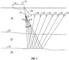
- FIG. 1 shows an example marine seismic data acquisition system as it is typically used on acquiring seismic data.
- a seismic vessel 14 moves along the surface of a body of water 12 such as a lake or the ocean.
- the marine seismic survey is intended to detect and record seismic signals related to structure and composition of various subsurface Earth formations 21, 23 below the water bottom 20.
- the seismic vessel 14 includes source actuation, data recording and navigation equipment, shown generally at 16, referred to for convenience as a "recording system.”
- the seismic vessel 14, or a different vessel can tow one or more seismic energy sources 18, or arrays of such sources in the water 12.
- the seismic vessel 14 or a different vessel tows at least one seismic streamer 10 near the surface of the water 12.
- the streamer 10 is coupled to the vessel 14 by a lead in cable 26.
- a plurality of sensor elements 24, or arrays of such sensor elements, are disposed at spaced apart locations along the streamer 10.
- the sensor elements 24, as will be explained in more detail below with reference to FIG. 4 are formed by mounting a seismic sensor inside a sensor holder. The structure of the streamer will be more fully explained with reference to FIGS. 4 through 6 .
- certain equipment in the recording system 16 causes the source 18 to actuate at selected times.
- the source 18 produces seismic energy 19 that emanates generally outwardly from the source 18.
- the energy 19 travels downwardly, through the water 12, and passes, at least in part, through the water bottom 20 into the formations 21, 23 below.
- Seismic energy 19 is at least partially reflected from one or more acoustic impedance boundaries 22 below the water bottom 20, and travels upwardly whereupon it may be detected by the sensors in each sensor element 24.
- Structure of the formations 21, 23, among other properties of the Earth's subsurface, can be inferred by travel time of the energy 19 and by characteristics of the detected energy such as its amplitude and phase.
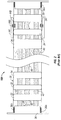
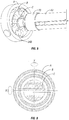
- FIG. 2 is a cut away view of a portion (segment) 10A of a typical marine seismic streamer (10 in FIG. 1 ).
- a streamer as shown in Figure 1 may extend behind the seismic vessel (14 in FIG. 1 ) for several kilometers, and is typically made from a plurality of streamer segments 10A as shown in Figure 2 connected end to end behind the vessel (14 in Figure 1 ).
- the streamer segment 10A in the present embodiment may be about 75 meters overall length.
- a streamer such as shown at 10 in Figure 1 thus may be formed by connecting a selected number of such segments 10A end to end.
- the segment 10A includes a jacket 30, which in the present embodiment can be made from 3.5 mm thick transparent polyurethane and has a nominal external diameter of about 62 millimeters.
- each axial end of the jacket 30 may be terminated by a coupling/termination plate 36.
- the coupling/termination block 36 may include rib elements 36A on an external surface of the coupling/termination block 36 that is inserted into the end of the jacket 30, so as to seal against the inner surface of the jacket 30 and to grip the coupling/termination block 36 to the jacket 30 when the jacket 30 is secured thereto by and external clamp (not shown).
- two strength members 42 are coupled to the interior of each coupling/termination block 36 and extend the length of the segment 10A.
- the strength members 42 may be made from a fiber rope made from a fiber sold under the trademark VECTRAN, which is a registered trademark of Hoechst Celanese Corp., New York, NY.
- the strength members 42 transmit axial load along the length of the segment 10A.
- the mating coupling/termination blocks 36 are coupled together using any suitable connector, so that the axial force is transmitted through the coupling/termination blocks 36 from the strength members 42 in one segment 10A to the strength member in the adjoining segment.
- the strength members are generally circular in cross section and are attached to a number of buoyancy spacers 32 disposed in the jacket 30.
- the buoyancy spacers are coupled to the strength members 42 at spaced apart locations along their length and laterally displaced from the center thereof.
- the buoyancy spacers 32 may be made from foamed polyurethane or other suitable, selected density material.
- the buoyancy spacers 32 have a density selected to provide the segment 10A preferably with approximately the same overall density as the water (12 in FIG. 1 ), so that the streamer (10 in Figure 1 ) will be substantially neutrally buoyant in the water (12 in FIG. 1 ).
- the buoyancy spacers 32 provide the segment 10A with an overall density very slightly less than that of fresh water. Appropriate overall density may then be adjusted in actual use by adding selected buoyancy spacers 32 and fill media having suitable specific gravity.
- the segment 10A includes a generally centrally located conductor cable 40 which can include a plurality of insulated electrical conductors (not shown separately), and may include one or more optical fibers (not shown).
- the cable 40 conducts electrical and/or optical signals from the seismic sensors ( FIG. 3 ) to the recording system (16 in FIG. 1 ).
- the cable 40 may in some implementations also carry electrical power to various signal processing circuits (not shown separately) disposed in one or more segments 10A, or disposed elsewhere along the streamer (10 in FIG. 1 ).
- the length of the conductor cable 40 within a cable segment 10A is generally longer than the axial length of the segment 10A under the largest expected axial stress on the segment 10A, so that the electrical conductors and optical fibers in the cable 40 will not experience any substantial axial stress when the streamer 10 is towed through the water by a vessel.
- the conductors and optical fibers may be terminated in a connector 38 disposed in each coupling/termination block 36 so that when the segments 10A are connected end to end, corresponding electrical and/or optical connections may be made between the electrical conductors and optical fibers in the conductor cable 40 in adjoining segments 10A.
- Sensors which in the present embodiment may be hydrophones, can be disposed inside sensor holders, shown in FIG. 2 generally at 34.
- the hydrophones in the present embodiment can be of a type known to those of ordinary skill in the art, including but not limited to those sold under model number T-2BX by Teledyne Geophysical Instruments, Houston, TX.
- each segment 10A may include 96 such hydrophones, disposed in arrays of sixteen individual hydrophones connected in electrical series. In a particular implementation of the invention, there are thus six such arrays, spaced apart from each other at about 12.5 meters. The spacing between individual hydrophones in each array should be selected so that the axial span of the array is at most equal to about one half the wavelength of the highest frequency seismic energy intended to be detected by the streamer (10 in FIG. 1 ).
- a compass bird 44 may be affixed to the outer surface of the jacket 30.
- the compass bird 44 includes a directional sensor (not shown separately) for determining the geographic orientation of the segment 10A at the location of the compass bird 44.
- the compass bird 44 may include an electromagnetic signal transducer 44A for communicating signals to a corresponding transducer 44B inside the jacket 30 for communication along the conductor cable 40 to the recording system (16 in FIG. 1 ). Measurements of direction are used, as is known in the art, to infer the position of the various sensors in the segment 10A, and thus along the entire length of the streamer (10 in FIG. 1 ).
- a compass bird will be affixed to the streamer (10 in FIG. 1 ) about every 300 meters (every four segments 10A).
- One type of compass bird is described in U.S. Patent No. 4,481,611 issued to Burrage.
- the interior space of the jacket 30 may be filled with a material 46 such as "BVF" (Buoyancy Void Filler), which may be a curable, synthetic urethane-based polymer.
- BVF Buoyancy Void Filler
- the BVF 46 serves to exclude fluid (water) from the interior of the jacket 30, to electrically insulate the various components inside the jacket 30, to add buoyancy to a streamer section and to transmit seismic energy freely through the jacket 30 to the sensors 34.
- the BVF 46 in its uncured state is essentially in liquid form. Upon cure, the BVF 46 no longer flows as a liquid, but instead becomes substantially solid. However, the BVF 46 upon cure retains some flexibility to bending stress, substantial elasticity, and freely transmits seismic energy to the sensors 24.
- the BVF used in the present embodiment only is one example of a gel-like substance that can be used to fill the interior of the streamer.
- Other materials could be also used. For example, heating a selected substance, such as a thermoplastic, above its melting point, and introducing the melted plastic into the interior of the jacket 30, and subsequent cooling, may also be used in a streamer according to the invention. Oil or similar material may also be used to fill the interior of the streamer.
- the sensor holders 34 are typically molded from a rigid, dense plastic to better protect the seismic sensors therein from damage during handling and use.
- the strength members 42 are typically tightly fit in, and adhesively bonded to through passages (52 in FIG 3 ) in the sensor spacers 34.
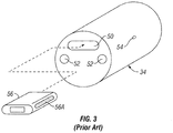
- FIG. 3 illustrates a manner known in the art in which seismic sensors are mounted in the sensor spacers.
- the space holder 34 includes an opening 50 shaped to accept a seismic sensor 56.
- the sensor 56 in this embodiment can be the model number T-2BX hydrophone made by Teledyne Geophysical Instruments, explained above with reference to Figure 2 .
- the housing of the sensor 56 includes ribs 56A on its lateral edges, such that when the sensor 56 is inserted into the opening 50, the sensor 56 is retained in the opening 50 by interference fit.
- the space holder 34 also includes through passages 52 through which the strength members (42 in FIG. 2 ) are inserted.
- An adhesive port 54 is provided on the space holder 34, and into which adhesive (not shown) is injected after the strength members (42 in FIG. 2 ) are inserted into the through passages 52.
- FIGS. 4 through 6 a marine sensor streamer according to the invention will now be explained with reference to FIGS. 4 through 6 .
- the principle for the present invention is to configure a strength member containing at least one strength member initially produced in the form of a substantially flat "belt", and physical characteristics that satisfy the axial load and elongation requirements for use in a towed streamer.
- the belt type strength member may be made from conventional materials and woven into its final form.
- the belt type strength member should have a width to thickness ratio of at least 10, and more preferably in a range of about 10 to 20. Such width to thickness ratio is expected to enable flexure transverse to the plane of the width of the strength member. Such flexure enables the strength member to be retained by chassis components, such as buoyancy and mounting spacers, so that the resulting configuration of the strength member is that of a substantially circular "tube.”
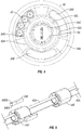
- FIG. 4 shows a cross section through one of the sensor holders 34A configured with strength members 42A as explained above.
- the sensor holder 34A may be made from materials as explained above and may have an outer diameter selected to fit snugly within the jacket 30.
- the sensor holder 34A may define an opening 34C generally concentric with the axis of the sensor holder 34A in which a sensor 56 may be mounted.
- the sensor 56 may be press fit in the opening 34C or may be retained in the opening by elastomer rings (not shown) or the like.
- the sensor holder defines one or more arcuate openings 34B generally disposed near the outer edge of the sensor holder 34A that may be used for passage through the streamer of cables and other devices.
- the cable 40 explained with reference to FIG. 2 may be disposed in one of the arcuate openings 34B as shown in FIG. 2 .
- the strength members 42A may be made as explained above and preferably have the width to thickness ratio explained above. Such ratio enables the strength members 42A to be inserted into and made to conform to substantially arcuate openings 34G disposed in the interior of the sensor holder 34A.
- the present example shows three strength members 42A in each of three corresponding openings 34G.
- the number of strength members and corresponding number of openings is a matter of discretion for the designer of the streamers, however a possible benefit of making a streamer according to the invention, namely more radially distribution of tension in the streamer, may be more effectively realized if the strength members (in their respective arcuate openings) in combination traverse at least 75 percent of the possible circumference. It should also be noted that at irrespective of the total possible traversed circumference, at least some of the circumference traversed by the strength members should include gaps or spaces to admit substantially unobstructed pressure waves to the sensor.
- FIG. 5 shows an oblique view of the strength members 42A and sensor holders 34A, one of which is shown in exploded view, to illustrate one possible configuration for the sensor holder 34A to facilitate assembly of the streamer. It should be noted that similar configuration of that shown for the sensor holder 34A may be used for any or all of the buoyancy spacers (32 in FIG. 2 ).
- the arcuate openings 34G in an unassembled sensor holder 34A may be accessed by removal of a substantially wedge shaped plug 34E.
- the plug 34E is configured to be inserted into a portion of the opening 34G so that its innermost surface just comes into to contact with the surface of the strength member 42A when the strength member 42A is fully seated in the arcuate opening 34G.
- An outer surface 34EB of the plug 34E may conform to the outer surface of the sensor holder 34A when the plug 34E is assembled thereto.
- the assembled sensor holder 34A will have a substantially smooth cylindrical surface for insertion into the jacket.
- a marine sensor streamer made as explained herein may provide one or more of the following benefits.
- the streamer sensors may be coaxially located with the axis of the streamer. Such streamer may have better cross sectional symmetry in all directions resulting in lower sensor noise. Symmetrical distribution of load stresses and vibrations related to towing may result in lower towing noise. Placement of a wiring harness in the outer perimeter of the concentric stress member and using of spacers for its mechanical protection and slack distribution may better protect the harness and may make for more efficient assembly of the streamer.
- FIG. 6 A portion of a fully assembled streamer harness is shown in FIG. 6 , including two sensor holders 34A having sensors in the center thereof, for example a hydrophone.
- particle motion sensors 57 may be mounted inside the strength members 42A and held in place, for example with band clamps 57A. Because of the arrangement of strength members in the present invention, such particle motion sensors may be substantially coaxial with the streamer.
- a non-limiting example of a particle motion sensor is described in U.S. Patent No. 7,239,577 issued to Tenghamn et al. and commonly owned with the present invention.
- FIG. 7 Another possible sensor holder is shown in end view in FIG. 7 .
- the sensor holder in FIG. 7 may be made from a single molded piece of plastic and include openings as shown.
- the strength members may be threaded through the openings 34G.
- FIG. 8 shows a termination plate for the strength members 42, which includes a termination member 70 that can couple to a pivot C disposed in a frame B having openings 34B for the chassis.
- the frame B and pivot C may be enabled to pivot about orthogonal axes with respect to an outer termination housing A. The respective rotations are illustrated in FIG. 9 .
- a seismic streamer having strength members according to the various aspects of the invention may have better distribution of axial loading within the cross section of the streamer, thereby decreasing noise transmitted along the streamer.
Landscapes
- Physics & Mathematics (AREA)
- Life Sciences & Earth Sciences (AREA)
- Engineering & Computer Science (AREA)
- Acoustics & Sound (AREA)
- Environmental & Geological Engineering (AREA)
- Geology (AREA)
- Remote Sensing (AREA)
- General Life Sciences & Earth Sciences (AREA)
- General Physics & Mathematics (AREA)
- Geophysics (AREA)
- Geophysics And Detection Of Objects (AREA)
- Testing Or Calibration Of Command Recording Devices (AREA)
Description
- The invention relates generally to the field of marine seismic survey apparatus and methods. More specifically, the invention relates to structures for marine seismic streamers that have reduced noise induced by effects of towing such streamers in the water.
- In a marine seismic survey, a seismic vessel travels on the surface of a body of water such as a lake or the ocean. The seismic vessel typically contains seismic acquisition control equipment, which includes devices such as navigation control, seismic source control, seismic sensor control, and signal recording devices. The seismic acquisition control equipment causes a seismic source towed in the body of water, by the seismic vessel or another vessel, to actuate at selected times. The seismic source may be any type well known in the art of seismic acquisition, including air guns or water guns, or most commonly, arrays of air guns. Seismic streamers, also called seismic cables, are elongate cable-like structures that are towed in the body of water by the seismic survey vessel or by another vessel. Typically, a plurality of seismic streamers is towed behind the seismic vessel laterally spaced apart from each other. The seismic streamers contain sensors to detect the seismic wavefields initiated by the seismic source and reflected from acoustic impedance boundaries in the subsurface Earth formations below the water bottom.
- Conventionally, seismic streamers contain pressure-responsive sensors such as hydrophones, but seismic streamers have also been proposed that contain particle motion sensors, such as geophones, in addition to hydrophones. The sensors are typically located at regular intervals along the length of seismic streamers.
- Seismic streamers also include electronic components, electrical wiring and may include other types of sensors. Seismic streamers are typically assembled from sections, each section being approximately 75 meters in length. A number of such sections are joined end to end, and can extend the assembled streamer to a total length of many thousands of meters. Position control devices, such as depth controllers, paravanes, and tail buoys are affixed to the streamer at selected positions and are used to regulate and monitor the movement of the streamer in the water. During operation, the seismic sources and streamers are typically submerged at a selected depth in the water. The seismic sources are typically operated at a depth of 5-15 meters below the water surface and the seismic streamers are typically operated at a depth of 5-40 meters.
- A typical streamer section consists of an external jacket, connectors, spacers, and strength members. The external jacket is formed from a flexible, acoustically transparent material such as polyurethane and protects the interior of the streamer section from water intrusion. The connectors are disposed at the ends of each streamer section and link the section mechanically, electrically and/or optically to adjacent streamer sections and, therefore, ultimately link it to the seismic towing vessel. There is at least one, and are usually two or more such strength members in each streamer section that extend the length of each streamer section from one end connector to the other. The strength members provide the streamer section with the capability to carry axial mechanical load. Generally, the strength members are in the shape of ropes. Typically, the strength members will be displaced from the center of the streamer to enable locating seismic sensors in the center of the streamer. Such placement of strength members has the effect of making strain distribution radially asymmetric.
-
US4,641,288 discloses a towed sonar array with a flat ribbon strength member that passes within the jacket but outside a canister containing electronics, without being in mechanical contact with the canister. -
US2005/0146984 discloses a seismic data acquisition cable with an access means for providing easy-to-reach access to wrap-around circuitry fitted inside a curved space within an electronics carrier. -
US2008/0144434 discloses a seismic streamer having wedge-shaped passages for cabling and sensors, which can be closed at a longitudinal end by a suitable shaped plug. - There continues to be a need for structures for marine sensor streamers that provide improved strain distribution within the cross sections thereof.
- One aspect of the invention is a seismic streamer comprising:
a jacket, covering an exterior of the streamer; at least one strength member extending the length of the jacket, the strength member formed as a substantially flat belt having a width to thickness ratio of at least 10; at least one sensor holder coupled to the at least one strength member, the at least one sensor holder including a sensor opening therein for retaining a seismic sensor and at least one arcuate opening for receiving the at least one strength member, the at least one arcuate opening laterally displaced from a center of the at least one sensor holder such that when the at least one strength member is disposed therein the at least one strength member is substantially tube shaped and substantially coaxial with the jacket, wherein each such arcuate opening is closed between an exterior surface of the corresponding strength member and an exterior surface of the sensor holder by a wedge shaped plug. - Other aspects and advantages of the invention will be apparent from the following description and the appended claims.
-
-
FIG. 1 shows typical marine seismic data acquisition using a streamer according to one embodiment of the invention. -
FIG. 2 shows a cut away view of one embodiment of a prior art streamer segment. -
FIG. 3 shows a typical prior art assembly of a seismic sensor to a spacer. -
FIG. 4 shows a cross section of a sensor holder, sensor, and strength member according to the invention. -
FIG. 5 shows an oblique view of the strength member assembled to sensor spacers or buoyancy spacers to illustrate one possible assembly method. -
FIG. 6 shows an oblique view of an assembled "dual sensor" seismic streamer. -
FIG. 7 shows an alternative sensor holder. -
FIG. 8 shows an articulated termination for the strength members. -
FIG. 9 shows the principle of operation of the articulated termination. -
FIG. 1 shows an example marine seismic data acquisition system as it is typically used on acquiring seismic data. Aseismic vessel 14 moves along the surface of a body ofwater 12 such as a lake or the ocean. The marine seismic survey is intended to detect and record seismic signals related to structure and composition of various subsurface Earthformations water bottom 20. Theseismic vessel 14 includes source actuation, data recording and navigation equipment, shown generally at 16, referred to for convenience as a "recording system." Theseismic vessel 14, or a different vessel (not shown), can tow one or moreseismic energy sources 18, or arrays of such sources in thewater 12. Theseismic vessel 14 or a different vessel tows at least oneseismic streamer 10 near the surface of thewater 12. Thestreamer 10 is coupled to thevessel 14 by a lead incable 26. A plurality ofsensor elements 24, or arrays of such sensor elements, are disposed at spaced apart locations along thestreamer 10. Thesensor elements 24, as will be explained in more detail below with reference toFIG. 4 , are formed by mounting a seismic sensor inside a sensor holder. The structure of the streamer will be more fully explained with reference toFIGS. 4 through 6 . - During operation, certain equipment (not shown separately) in the
recording system 16 causes thesource 18 to actuate at selected times. When actuated, thesource 18 producesseismic energy 19 that emanates generally outwardly from thesource 18. Theenergy 19 travels downwardly, through thewater 12, and passes, at least in part, through thewater bottom 20 into theformations Seismic energy 19 is at least partially reflected from one or moreacoustic impedance boundaries 22 below thewater bottom 20, and travels upwardly whereupon it may be detected by the sensors in eachsensor element 24. Structure of theformations energy 19 and by characteristics of the detected energy such as its amplitude and phase. - Having explained the general method of operation of a marine seismic streamer, an example embodiment of a prior art streamer will be explained with reference to
FIG. 2 . The purpose for explaining the prior art streamer structure inFIG. 2 is to more clearly show the differences between prior art streamer construction and examples of a streamer according to the invention.FIG. 2 is a cut away view of a portion (segment) 10A of a typical marine seismic streamer (10 inFIG. 1 ). A streamer as shown inFigure 1 may extend behind the seismic vessel (14 inFIG. 1 ) for several kilometers, and is typically made from a plurality ofstreamer segments 10A as shown inFigure 2 connected end to end behind the vessel (14 inFigure 1 ). - The
streamer segment 10A in the present embodiment may be about 75 meters overall length. A streamer such as shown at 10 inFigure 1 thus may be formed by connecting a selected number ofsuch segments 10A end to end. Thesegment 10A includes ajacket 30, which in the present embodiment can be made from 3.5 mm thick transparent polyurethane and has a nominal external diameter of about 62 millimeters. In eachsegment 10A, each axial end of thejacket 30 may be terminated by a coupling/termination plate 36. The coupling/termination block 36 may includerib elements 36A on an external surface of the coupling/termination block 36 that is inserted into the end of thejacket 30, so as to seal against the inner surface of thejacket 30 and to grip the coupling/termination block 36 to thejacket 30 when thejacket 30 is secured thereto by and external clamp (not shown). In the present embodiment, twostrength members 42 are coupled to the interior of each coupling/termination block 36 and extend the length of thesegment 10A. In a particular implementation of the invention, thestrength members 42 may be made from a fiber rope made from a fiber sold under the trademark VECTRAN, which is a registered trademark of Hoechst Celanese Corp., New York, NY. Thestrength members 42 transmit axial load along the length of thesegment 10A. When onesegment 10A is coupled end to end to another such segment (not shown inFIG. 2 ), the mating coupling/termination blocks 36 are coupled together using any suitable connector, so that the axial force is transmitted through the coupling/termination blocks 36 from thestrength members 42 in onesegment 10A to the strength member in the adjoining segment. - In prior art streamers such as the one shown in
FIG. 2 , the strength members are generally circular in cross section and are attached to a number ofbuoyancy spacers 32 disposed in thejacket 30. The buoyancy spacers are coupled to thestrength members 42 at spaced apart locations along their length and laterally displaced from the center thereof. The buoyancy spacers 32 may be made from foamed polyurethane or other suitable, selected density material. The buoyancy spacers 32 have a density selected to provide thesegment 10A preferably with approximately the same overall density as the water (12 inFIG. 1 ), so that the streamer (10 inFigure 1 ) will be substantially neutrally buoyant in the water (12 inFIG. 1 ). As a practical matter, thebuoyancy spacers 32 provide thesegment 10A with an overall density very slightly less than that of fresh water. Appropriate overall density may then be adjusted in actual use by adding selectedbuoyancy spacers 32 and fill media having suitable specific gravity. - The
segment 10A includes a generally centrally locatedconductor cable 40 which can include a plurality of insulated electrical conductors (not shown separately), and may include one or more optical fibers (not shown). Thecable 40 conducts electrical and/or optical signals from the seismic sensors (FIG. 3 ) to the recording system (16 inFIG. 1 ). Thecable 40 may in some implementations also carry electrical power to various signal processing circuits (not shown separately) disposed in one ormore segments 10A, or disposed elsewhere along the streamer (10 inFIG. 1 ). The length of theconductor cable 40 within acable segment 10A is generally longer than the axial length of thesegment 10A under the largest expected axial stress on thesegment 10A, so that the electrical conductors and optical fibers in thecable 40 will not experience any substantial axial stress when thestreamer 10 is towed through the water by a vessel. The conductors and optical fibers may be terminated in aconnector 38 disposed in each coupling/termination block 36 so that when thesegments 10A are connected end to end, corresponding electrical and/or optical connections may be made between the electrical conductors and optical fibers in theconductor cable 40 in adjoiningsegments 10A. - Sensors, which in the present embodiment may be hydrophones, can be disposed inside sensor holders, shown in
FIG. 2 generally at 34. The hydrophones in the present embodiment can be of a type known to those of ordinary skill in the art, including but not limited to those sold under model number T-2BX by Teledyne Geophysical Instruments, Houston, TX. In the present embodiment, eachsegment 10A may include 96 such hydrophones, disposed in arrays of sixteen individual hydrophones connected in electrical series. In a particular implementation of the invention, there are thus six such arrays, spaced apart from each other at about 12.5 meters. The spacing between individual hydrophones in each array should be selected so that the axial span of the array is at most equal to about one half the wavelength of the highest frequency seismic energy intended to be detected by the streamer (10 inFIG. 1 ). - At selected positions along the streamer a
compass bird 44 may be affixed to the outer surface of thejacket 30. Thecompass bird 44 includes a directional sensor (not shown separately) for determining the geographic orientation of thesegment 10A at the location of thecompass bird 44. Thecompass bird 44 may include an electromagnetic signal transducer 44A for communicating signals to acorresponding transducer 44B inside thejacket 30 for communication along theconductor cable 40 to the recording system (16 inFIG. 1 ). Measurements of direction are used, as is known in the art, to infer the position of the various sensors in thesegment 10A, and thus along the entire length of the streamer (10 inFIG. 1 ). Typically, a compass bird will be affixed to the streamer (10 inFIG. 1 ) about every 300 meters (every foursegments 10A). One type of compass bird is described inU.S. Patent No. 4,481,611 issued to Burrage. - In the present embodiment, the interior space of the
jacket 30 may be filled with a material 46 such as "BVF" (Buoyancy Void Filler), which may be a curable, synthetic urethane-based polymer. TheBVF 46 serves to exclude fluid (water) from the interior of thejacket 30, to electrically insulate the various components inside thejacket 30, to add buoyancy to a streamer section and to transmit seismic energy freely through thejacket 30 to thesensors 34. TheBVF 46 in its uncured state is essentially in liquid form. Upon cure, theBVF 46 no longer flows as a liquid, but instead becomes substantially solid. However, theBVF 46 upon cure retains some flexibility to bending stress, substantial elasticity, and freely transmits seismic energy to thesensors 24. It should be understood that the BVF used in the present embodiment only is one example of a gel-like substance that can be used to fill the interior of the streamer. Other materials could be also used. For example, heating a selected substance, such as a thermoplastic, above its melting point, and introducing the melted plastic into the interior of thejacket 30, and subsequent cooling, may also be used in a streamer according to the invention. Oil or similar material may also be used to fill the interior of the streamer. - The
sensor holders 34, as explained in the Background section herein, are typically molded from a rigid, dense plastic to better protect the seismic sensors therein from damage during handling and use. Thestrength members 42 are typically tightly fit in, and adhesively bonded to through passages (52 inFIG 3 ) in thesensor spacers 34. -
FIG. 3 illustrates a manner known in the art in which seismic sensors are mounted in the sensor spacers. Thespace holder 34 includes anopening 50 shaped to accept aseismic sensor 56. Thesensor 56 in this embodiment can be the model number T-2BX hydrophone made by Teledyne Geophysical Instruments, explained above with reference toFigure 2 . The housing of thesensor 56 includesribs 56A on its lateral edges, such that when thesensor 56 is inserted into theopening 50, thesensor 56 is retained in theopening 50 by interference fit. Thespace holder 34 also includes throughpassages 52 through which the strength members (42 inFIG. 2 ) are inserted. Anadhesive port 54 is provided on thespace holder 34, and into which adhesive (not shown) is injected after the strength members (42 inFIG. 2 ) are inserted into the throughpassages 52. - Having explained typical prior art marine streamer structures, a marine sensor streamer according to the invention will now be explained with reference to
FIGS. 4 through 6 . - The principle for the present invention is to configure a strength member containing at least one strength member initially produced in the form of a substantially flat "belt", and physical characteristics that satisfy the axial load and elongation requirements for use in a towed streamer. The belt type strength member may be made from conventional materials and woven into its final form. The belt type strength member should have a width to thickness ratio of at least 10, and more preferably in a range of about 10 to 20. Such width to thickness ratio is expected to enable flexure transverse to the plane of the width of the strength member. Such flexure enables the strength member to be retained by chassis components, such as buoyancy and mounting spacers, so that the resulting configuration of the strength member is that of a substantially circular "tube."
-
FIG. 4 shows a cross section through one of thesensor holders 34A configured withstrength members 42A as explained above. Thesensor holder 34A may be made from materials as explained above and may have an outer diameter selected to fit snugly within thejacket 30. Thesensor holder 34A may define anopening 34C generally concentric with the axis of thesensor holder 34A in which asensor 56 may be mounted. Thesensor 56 may be press fit in theopening 34C or may be retained in the opening by elastomer rings (not shown) or the like. The sensor holder defines one or morearcuate openings 34B generally disposed near the outer edge of thesensor holder 34A that may be used for passage through the streamer of cables and other devices. Thecable 40 explained with reference toFIG. 2 may be disposed in one of thearcuate openings 34B as shown inFIG. 2 . - The
strength members 42A may be made as explained above and preferably have the width to thickness ratio explained above. Such ratio enables thestrength members 42A to be inserted into and made to conform to substantiallyarcuate openings 34G disposed in the interior of thesensor holder 34A. The present example shows threestrength members 42A in each of three correspondingopenings 34G. The number of strength members and corresponding number of openings is a matter of discretion for the designer of the streamers, however a possible benefit of making a streamer according to the invention, namely more radially distribution of tension in the streamer, may be more effectively realized if the strength members (in their respective arcuate openings) in combination traverse at least 75 percent of the possible circumference. It should also be noted that at irrespective of the total possible traversed circumference, at least some of the circumference traversed by the strength members should include gaps or spaces to admit substantially unobstructed pressure waves to the sensor. -
FIG. 5 shows an oblique view of thestrength members 42A andsensor holders 34A, one of which is shown in exploded view, to illustrate one possible configuration for thesensor holder 34A to facilitate assembly of the streamer. It should be noted that similar configuration of that shown for thesensor holder 34A may be used for any or all of the buoyancy spacers (32 inFIG. 2 ). Thearcuate openings 34G in anunassembled sensor holder 34A may be accessed by removal of a substantially wedge shapedplug 34E. Theplug 34E is configured to be inserted into a portion of theopening 34G so that its innermost surface just comes into to contact with the surface of thestrength member 42A when thestrength member 42A is fully seated in thearcuate opening 34G. An outer surface 34EB of theplug 34E may conform to the outer surface of thesensor holder 34A when theplug 34E is assembled thereto. When theplugs 34E are assembled, as shown in thebackground sensor holder 34A inFIG. 5 , the assembledsensor holder 34A will have a substantially smooth cylindrical surface for insertion into the jacket. - A marine sensor streamer made as explained herein may provide one or more of the following benefits. The streamer sensors may be coaxially located with the axis of the streamer. Such streamer may have better cross sectional symmetry in all directions resulting in lower sensor noise. Symmetrical distribution of load stresses and vibrations related to towing may result in lower towing noise. Placement of a wiring harness in the outer perimeter of the concentric stress member and using of spacers for its mechanical protection and slack distribution may better protect the harness and may make for more efficient assembly of the streamer.
- A portion of a fully assembled streamer harness is shown in
FIG. 6 , including twosensor holders 34A having sensors in the center thereof, for example a hydrophone. In the present example,particle motion sensors 57 may be mounted inside thestrength members 42A and held in place, for example with band clamps 57A. Because of the arrangement of strength members in the present invention, such particle motion sensors may be substantially coaxial with the streamer. A non-limiting example of a particle motion sensor is described inU.S. Patent No. 7,239,577 issued to Tenghamn et al. and commonly owned with the present invention. - Another possible sensor holder is shown in end view in
FIG. 7 . The sensor holder inFIG. 7 may be made from a single molded piece of plastic and include openings as shown. The strength members may be threaded through theopenings 34G. -
FIG. 8 shows a termination plate for thestrength members 42, which includes atermination member 70 that can couple to a pivot C disposed in a frameB having openings 34B for the chassis. The frame B and pivot C may be enabled to pivot about orthogonal axes with respect to an outer termination housing A. The respective rotations are illustrated inFIG. 9 . - A seismic streamer having strength members according to the various aspects of the invention may have better distribution of axial loading within the cross section of the streamer, thereby decreasing noise transmitted along the streamer.
Claims (16)
- A seismic streamer (10), comprising:a jacket (30), covering an exterior of the streamer;at least one strength member (42A) extending the length of the jacket, the strength member formed as a substantially flat belt having a width to thickness ratio of at least 10;at least one sensor holder (34A) coupled to the at least one strength member (42A), the at least one sensor holder including a sensor opening (34C) therein for retaining a seismic sensor (56) and at least one arcuate opening (34G) for receiving the at least one strength member (42A), the at least one arcuate opening (34G) laterally displaced from a center of the at least one sensor holder (34A) such that when the at least one strength member (42A) is disposed therein the at least one strength member is substantially tube shaped and substantially coaxial with the jacket, (30)characterised in that each such arcuate opening (34G) is closed between an exterior surface of the corresponding strength member (42A) and an exterior surface of the sensor holder (34A) by a wedge shaped plug (34E).
- The streamer of claim 1 wherein the at least one sensor holder (34A) comprises a plurality of circumferentially spaced apart arcuate openings (34G) each configured to receive a corresponding strength member (42A), each corresponding strength member being formed as a substantially flat belt having a width to thickness ratio of at least 10.
- The streamer of claim 1 or claim 2 further comprising:a plurality of sensor holders (34A) coupled to the at least one strength member (42A), each sensor holder including at least one arcuate opening (34G) for receiving the at least one strength member, the at least one arcuate opening laterally displaced from a center of each sensor holder such that when the at least one strength member is disposed therein the at least one strength member is substantially tube shaped and substantially coaxial with the jacket (30); andat least one particle motion seismic sensor (57) disposed in the at least one strength member at a longitudinal position between two of the sensor holders.
- A seismic streamer according to claim 1, comprising:a plurality of said strength members (42A) extending the length of the jacket (30); anda plurality of said sensor holders (34A) coupled to the plurality of strength members (42A), each sensor holder including a plurality of circumferentially spaced apart arcuate openings (34G) each for receiving a corresponding strength member (42A), each arcuate opening laterally displaced from a center of the sensor holder such that when each strength member is disposed respectively therein the strength members are substantially tube shaped and substantially coaxial with the jacket.
- The streamer of any of claims 2 to 4 wherein the plurality of arcuate openings (34G) traverse at least 75 percent of a total possible circumference.
- The streamer of any of claims 4 to 5, further comprising at least one particle motion seismic sensor (57) disposed within the strength members (42A) at a longitudinal position between two of the sensor holders (34A).
- The streamer of any of the preceding claims wherein the or each strength member comprises woven fiber.
- The streamer of any of the preceding claims wherein the or each sensor holder (34A) has an external diameter selected to substantially match an internal diameter of the jacket (30), the sensor opening (34C) being substantially coaxial with the jacket for retaining a sensor (56) therein.
- The streamer of claim 8 wherein the or each sensor holder (34A) comprises an arcuate opening (34B) disposed between the strength member (42A) and an outer surface of the sensor holder to enable longitudinal passage of a cable therethrough.
- The streamer of any of the preceding claims further comprising buoyancy spacers (32) disposed along the strength member(s) (42A) and inside the jacket (30) at spaced apart locations, the spacers having a density selected to provide the streamer with a selected overall density.
- The streamer of claim 10 wherein the buoyancy spacers (32) comprise foamed polyurethane.
- The streamer of any of the preceding claims further comprising a cable (40) disposed inside the jacket (30), the cable having at least one of electrical conductors and an optical fiber, the cable adapted to carry signals from at least one sensor (56) disposed in the at least one sensor holder (34A) to a recording system.
- The streamer of any of the preceding claims wherein the sensor opening (34C) of the at least one sensor holder (34A) is in a center thereof for retaining a sensor (56) such as a hydrophone substantially coaxially with the jacket (30).
- The streamer of any of the preceding claims further comprising a termination plate (36) coupled to each axial end of the jacket (30), the termination plates each coupled to the strength member(s) (42A) at an axial end thereof, the termination plates adapted to couple to a corresponding termination plate in another segment of the streamer so as to transmit axial force therethrough.
- The streamer of claim 14 wherein the termination plate (36) is articulated.
- A streamer according to any of the preceding claims, wherein the jacket (30) comprises polyurethane.
Applications Claiming Priority (1)
| Application Number | Priority Date | Filing Date | Title |
|---|---|---|---|
| US12/584,511 US8995221B2 (en) | 2009-09-08 | 2009-09-08 | Towed marine sensor streamer having concentric stress member |
Publications (3)
| Publication Number | Publication Date |
|---|---|
| EP2293115A2 EP2293115A2 (en) | 2011-03-09 |
| EP2293115A3 EP2293115A3 (en) | 2012-08-15 |
| EP2293115B1 true EP2293115B1 (en) | 2020-05-27 |
Family
ID=43413664
Family Applications (1)
| Application Number | Title | Priority Date | Filing Date |
|---|---|---|---|
| EP10173448.1A Active EP2293115B1 (en) | 2009-09-08 | 2010-08-19 | Towed marine sensor streamer having concentric stress member |
Country Status (3)
| Country | Link |
|---|---|
| US (1) | US8995221B2 (en) |
| EP (1) | EP2293115B1 (en) |
| AU (1) | AU2010214728B2 (en) |
Families Citing this family (11)
| Publication number | Priority date | Publication date | Assignee | Title |
|---|---|---|---|---|
| US8947973B2 (en) * | 2010-11-17 | 2015-02-03 | WesternGeco L.L.P. | Active detection of marine mammals during seismic surveying |
| US9720123B2 (en) * | 2011-11-11 | 2017-08-01 | Pgs Geophysical As | Electrode assembly for marine electromagnetic geophysical survey sources |
| CA2874297C (en) * | 2012-06-11 | 2020-06-09 | Dsm Ip Assets B.V. | Endless shaped article |
| US9753168B2 (en) | 2013-03-08 | 2017-09-05 | Pgs Geophysical As | Marine streamer having variable stiffness |
| US20150346366A1 (en) * | 2014-05-28 | 2015-12-03 | Sercel | Seismic acquisition system comprising at least one connecting module to which is connected an auxiliary equipment, corresponding connecting module and data management system |
| WO2016200854A1 (en) * | 2015-06-08 | 2016-12-15 | Westerngeco Llc | Seismic sensor cable |
| US10067251B2 (en) * | 2015-06-29 | 2018-09-04 | Pgs Geophysical As | Stress member connector |
| KR102576784B1 (en) * | 2016-02-05 | 2023-09-07 | 엘에스전선 주식회사 | Sonic Sensing Cable |
| US10613241B2 (en) | 2016-06-24 | 2020-04-07 | Pgs Geophysical As | Streamer manufacturing |
| US10557953B2 (en) | 2016-06-30 | 2020-02-11 | Pgs Geophysical As | Molded snap-in plug and device and method for using same |
| US11079506B2 (en) | 2016-12-16 | 2021-08-03 | Pgs Geophysical As | Multicomponent streamer |
Family Cites Families (13)
| Publication number | Priority date | Publication date | Assignee | Title |
|---|---|---|---|---|
| US4481611A (en) | 1980-01-25 | 1984-11-06 | Shell Oil Company | Seismic cable compass system |
| US4541288A (en) * | 1983-10-27 | 1985-09-17 | General Electric Company | Operating circuit for magnetoelastic force/pressure sensors |
| US4641288A (en) * | 1985-11-07 | 1987-02-03 | Hughes Aircraft Company | Ribbon termination member |
| AU722852B2 (en) | 1995-09-22 | 2000-08-10 | Ion Geophysical Corporation | Coil support device for an underwater cable |
| CN1270675A (en) | 1997-09-19 | 2000-10-18 | 施鲁博格控股有限公司 | Towing seismic streamer used in marine seismic surveying |
| US6128251A (en) * | 1999-04-16 | 2000-10-03 | Syntron, Inc. | Solid marine seismic cable |
| US6559383B1 (en) * | 1999-07-21 | 2003-05-06 | Input/Output, Inc. | Connector housing |
| AUPS015702A0 (en) | 2002-01-25 | 2002-02-14 | Thales Underwater Systems Pty Limited | Electronics carrying module |
| US7239577B2 (en) | 2002-08-30 | 2007-07-03 | Pgs Americas, Inc. | Apparatus and methods for multicomponent marine geophysical data gathering |
| US7733740B2 (en) * | 2006-09-22 | 2010-06-08 | Pgs Geophysical As | Sensor mount for marine seismic streamer |
| US7881159B2 (en) | 2006-12-18 | 2011-02-01 | Pgs Geophysical As | Seismic streamers which attentuate longitudinally traveling waves |
| US7715988B2 (en) * | 2007-06-13 | 2010-05-11 | Westerngeco L.L.C. | Interpolating and deghosting multi-component seismic sensor data |
| US20090010101A1 (en) | 2007-07-05 | 2009-01-08 | Nils Lunde | Seismic streamer having longitudinally symmetrically sensitive sensors to reduce effects of longitudinally traveling waves |
-
2009
- 2009-09-08 US US12/584,511 patent/US8995221B2/en not_active Expired - Fee Related
-
2010
- 2010-08-19 EP EP10173448.1A patent/EP2293115B1/en active Active
- 2010-08-30 AU AU2010214728A patent/AU2010214728B2/en not_active Ceased
Non-Patent Citations (1)
| Title |
|---|
| None * |
Also Published As
| Publication number | Publication date |
|---|---|
| US20110058449A1 (en) | 2011-03-10 |
| US8995221B2 (en) | 2015-03-31 |
| EP2293115A3 (en) | 2012-08-15 |
| AU2010214728A1 (en) | 2011-03-24 |
| AU2010214728B2 (en) | 2016-02-18 |
| EP2293115A2 (en) | 2011-03-09 |
Similar Documents
| Publication | Publication Date | Title |
|---|---|---|
| EP2293115B1 (en) | Towed marine sensor streamer having concentric stress member | |
| AU2007242934B2 (en) | Seismic streamer having directionally sensitive sensors in an array to attentuate longitudinally traveling waves | |
| AU2008202686B2 (en) | Seismic streamer having longitudinally symmetrically sensitive sensors to reduce effects of longitudinally traveling waves | |
| US7298672B1 (en) | Marine seismic streamer having acoustic isolation between strength members and sensor mounting | |
| US7733740B2 (en) | Sensor mount for marine seismic streamer | |
| US7545703B2 (en) | Marine seismic streamer with varying spacer distances for reducing towing noise | |
| AU2007201880B2 (en) | System for reducing towing noise in marine seismic survey streams | |
| US7693005B2 (en) | Sensor streamer having two-layer jacket | |
| US8319497B2 (en) | Marine sensor streamer having pressure activated stiffness enhancement | |
| US20080186803A1 (en) | Fluid filled sensor mount for gel-filled streamer and streamer made therewith | |
| US20070258320A1 (en) | System for seismic sensor mounting in a marine seismic streamer | |
| GB2421078A (en) | Controlling the internal geometry of a seismic streamer during introduction of filler material | |
| US20080008034A1 (en) | Marine seismic survey streamer configuration for reducing towing noise | |
| GB2439816A (en) | Marine seismic survey streamer construction for reducing towing noise | |
| US20120155222A1 (en) | Method and apparatus for terminating rope and its application to seismic streamer strength members | |
| GB2439815A (en) | Marine seismic streamer with varying spacer distances for reducing towing noise |
Legal Events
| Date | Code | Title | Description |
|---|---|---|---|
| PUAI | Public reference made under article 153(3) epc to a published international application that has entered the european phase |
Free format text: ORIGINAL CODE: 0009012 |
|
| AK | Designated contracting states |
Kind code of ref document: A2 Designated state(s): AL AT BE BG CH CY CZ DE DK EE ES FI FR GB GR HR HU IE IS IT LI LT LU LV MC MK MT NL NO PL PT RO SE SI SK SM TR |
|
| AX | Request for extension of the european patent |
Extension state: BA ME RS |
|
| RIC1 | Information provided on ipc code assigned before grant |
Ipc: G01V 1/20 20060101AFI20120316BHEP |
|
| PUAL | Search report despatched |
Free format text: ORIGINAL CODE: 0009013 |
|
| AK | Designated contracting states |
Kind code of ref document: A3 Designated state(s): AL AT BE BG CH CY CZ DE DK EE ES FI FR GB GR HR HU IE IS IT LI LT LU LV MC MK MT NL NO PL PT RO SE SI SK SM TR |
|
| AX | Request for extension of the european patent |
Extension state: BA ME RS |
|
| RIC1 | Information provided on ipc code assigned before grant |
Ipc: G01V 1/20 20060101AFI20120706BHEP |
|
| 17P | Request for examination filed |
Effective date: 20121106 |
|
| 17Q | First examination report despatched |
Effective date: 20121205 |
|
| RAP1 | Party data changed (applicant data changed or rights of an application transferred) |
Owner name: PGS GEOPHYSICAL AS |
|
| STAA | Information on the status of an ep patent application or granted ep patent |
Free format text: STATUS: EXAMINATION IS IN PROGRESS |
|
| GRAP | Despatch of communication of intention to grant a patent |
Free format text: ORIGINAL CODE: EPIDOSNIGR1 |
|
| STAA | Information on the status of an ep patent application or granted ep patent |
Free format text: STATUS: GRANT OF PATENT IS INTENDED |
|
| INTG | Intention to grant announced |
Effective date: 20191218 |
|
| GRAS | Grant fee paid |
Free format text: ORIGINAL CODE: EPIDOSNIGR3 |
|
| GRAA | (expected) grant |
Free format text: ORIGINAL CODE: 0009210 |
|
| STAA | Information on the status of an ep patent application or granted ep patent |
Free format text: STATUS: THE PATENT HAS BEEN GRANTED |
|
| AK | Designated contracting states |
Kind code of ref document: B1 Designated state(s): AL AT BE BG CH CY CZ DE DK EE ES FI FR GB GR HR HU IE IS IT LI LT LU LV MC MK MT NL NO PL PT RO SE SI SK SM TR |
|
| REG | Reference to a national code |
Ref country code: GB Ref legal event code: FG4D |
|
| REG | Reference to a national code |
Ref country code: CH Ref legal event code: EP |
|
| REG | Reference to a national code |
Ref country code: AT Ref legal event code: REF Ref document number: 1275116 Country of ref document: AT Kind code of ref document: T Effective date: 20200615 |
|
| REG | Reference to a national code |
Ref country code: DE Ref legal event code: R096 Ref document number: 602010064441 Country of ref document: DE |
|
| REG | Reference to a national code |
Ref country code: NO Ref legal event code: T2 Effective date: 20200527 |
|
| REG | Reference to a national code |
Ref country code: LT Ref legal event code: MG4D |
|
| PG25 | Lapsed in a contracting state [announced via postgrant information from national office to epo] |
Ref country code: LT Free format text: LAPSE BECAUSE OF FAILURE TO SUBMIT A TRANSLATION OF THE DESCRIPTION OR TO PAY THE FEE WITHIN THE PRESCRIBED TIME-LIMIT Effective date: 20200527 Ref country code: FI Free format text: LAPSE BECAUSE OF FAILURE TO SUBMIT A TRANSLATION OF THE DESCRIPTION OR TO PAY THE FEE WITHIN THE PRESCRIBED TIME-LIMIT Effective date: 20200527 Ref country code: SE Free format text: LAPSE BECAUSE OF FAILURE TO SUBMIT A TRANSLATION OF THE DESCRIPTION OR TO PAY THE FEE WITHIN THE PRESCRIBED TIME-LIMIT Effective date: 20200527 Ref country code: PT Free format text: LAPSE BECAUSE OF FAILURE TO SUBMIT A TRANSLATION OF THE DESCRIPTION OR TO PAY THE FEE WITHIN THE PRESCRIBED TIME-LIMIT Effective date: 20200928 Ref country code: IS Free format text: LAPSE BECAUSE OF FAILURE TO SUBMIT A TRANSLATION OF THE DESCRIPTION OR TO PAY THE FEE WITHIN THE PRESCRIBED TIME-LIMIT Effective date: 20200927 Ref country code: GR Free format text: LAPSE BECAUSE OF FAILURE TO SUBMIT A TRANSLATION OF THE DESCRIPTION OR TO PAY THE FEE WITHIN THE PRESCRIBED TIME-LIMIT Effective date: 20200828 |
|
| REG | Reference to a national code |
Ref country code: NL Ref legal event code: MP Effective date: 20200527 |
|
| PG25 | Lapsed in a contracting state [announced via postgrant information from national office to epo] |
Ref country code: LV Free format text: LAPSE BECAUSE OF FAILURE TO SUBMIT A TRANSLATION OF THE DESCRIPTION OR TO PAY THE FEE WITHIN THE PRESCRIBED TIME-LIMIT Effective date: 20200527 Ref country code: BG Free format text: LAPSE BECAUSE OF FAILURE TO SUBMIT A TRANSLATION OF THE DESCRIPTION OR TO PAY THE FEE WITHIN THE PRESCRIBED TIME-LIMIT Effective date: 20200827 Ref country code: HR Free format text: LAPSE BECAUSE OF FAILURE TO SUBMIT A TRANSLATION OF THE DESCRIPTION OR TO PAY THE FEE WITHIN THE PRESCRIBED TIME-LIMIT Effective date: 20200527 |
|
| REG | Reference to a national code |
Ref country code: AT Ref legal event code: MK05 Ref document number: 1275116 Country of ref document: AT Kind code of ref document: T Effective date: 20200527 |
|
| PG25 | Lapsed in a contracting state [announced via postgrant information from national office to epo] |
Ref country code: AL Free format text: LAPSE BECAUSE OF FAILURE TO SUBMIT A TRANSLATION OF THE DESCRIPTION OR TO PAY THE FEE WITHIN THE PRESCRIBED TIME-LIMIT Effective date: 20200527 Ref country code: NL Free format text: LAPSE BECAUSE OF FAILURE TO SUBMIT A TRANSLATION OF THE DESCRIPTION OR TO PAY THE FEE WITHIN THE PRESCRIBED TIME-LIMIT Effective date: 20200527 |
|
| PG25 | Lapsed in a contracting state [announced via postgrant information from national office to epo] |
Ref country code: ES Free format text: LAPSE BECAUSE OF FAILURE TO SUBMIT A TRANSLATION OF THE DESCRIPTION OR TO PAY THE FEE WITHIN THE PRESCRIBED TIME-LIMIT Effective date: 20200527 Ref country code: CZ Free format text: LAPSE BECAUSE OF FAILURE TO SUBMIT A TRANSLATION OF THE DESCRIPTION OR TO PAY THE FEE WITHIN THE PRESCRIBED TIME-LIMIT Effective date: 20200527 Ref country code: RO Free format text: LAPSE BECAUSE OF FAILURE TO SUBMIT A TRANSLATION OF THE DESCRIPTION OR TO PAY THE FEE WITHIN THE PRESCRIBED TIME-LIMIT Effective date: 20200527 Ref country code: SM Free format text: LAPSE BECAUSE OF FAILURE TO SUBMIT A TRANSLATION OF THE DESCRIPTION OR TO PAY THE FEE WITHIN THE PRESCRIBED TIME-LIMIT Effective date: 20200527 Ref country code: EE Free format text: LAPSE BECAUSE OF FAILURE TO SUBMIT A TRANSLATION OF THE DESCRIPTION OR TO PAY THE FEE WITHIN THE PRESCRIBED TIME-LIMIT Effective date: 20200527 Ref country code: DK Free format text: LAPSE BECAUSE OF FAILURE TO SUBMIT A TRANSLATION OF THE DESCRIPTION OR TO PAY THE FEE WITHIN THE PRESCRIBED TIME-LIMIT Effective date: 20200527 Ref country code: IT Free format text: LAPSE BECAUSE OF FAILURE TO SUBMIT A TRANSLATION OF THE DESCRIPTION OR TO PAY THE FEE WITHIN THE PRESCRIBED TIME-LIMIT Effective date: 20200527 Ref country code: AT Free format text: LAPSE BECAUSE OF FAILURE TO SUBMIT A TRANSLATION OF THE DESCRIPTION OR TO PAY THE FEE WITHIN THE PRESCRIBED TIME-LIMIT Effective date: 20200527 |
|
| PG25 | Lapsed in a contracting state [announced via postgrant information from national office to epo] |
Ref country code: PL Free format text: LAPSE BECAUSE OF FAILURE TO SUBMIT A TRANSLATION OF THE DESCRIPTION OR TO PAY THE FEE WITHIN THE PRESCRIBED TIME-LIMIT Effective date: 20200527 Ref country code: SK Free format text: LAPSE BECAUSE OF FAILURE TO SUBMIT A TRANSLATION OF THE DESCRIPTION OR TO PAY THE FEE WITHIN THE PRESCRIBED TIME-LIMIT Effective date: 20200527 |
|
| REG | Reference to a national code |
Ref country code: DE Ref legal event code: R119 Ref document number: 602010064441 Country of ref document: DE Ref country code: DE Ref legal event code: R097 Ref document number: 602010064441 Country of ref document: DE |
|
| REG | Reference to a national code |
Ref country code: NO Ref legal event code: MMEP |
|
| PG25 | Lapsed in a contracting state [announced via postgrant information from national office to epo] |
Ref country code: MC Free format text: LAPSE BECAUSE OF FAILURE TO SUBMIT A TRANSLATION OF THE DESCRIPTION OR TO PAY THE FEE WITHIN THE PRESCRIBED TIME-LIMIT Effective date: 20200527 |
|
| REG | Reference to a national code |
Ref country code: CH Ref legal event code: PL |
|
| PLBE | No opposition filed within time limit |
Free format text: ORIGINAL CODE: 0009261 |
|
| STAA | Information on the status of an ep patent application or granted ep patent |
Free format text: STATUS: NO OPPOSITION FILED WITHIN TIME LIMIT |
|
| GBPC | Gb: european patent ceased through non-payment of renewal fee |
Effective date: 20200827 |
|
| PG25 | Lapsed in a contracting state [announced via postgrant information from national office to epo] |
Ref country code: NO Free format text: LAPSE BECAUSE OF NON-PAYMENT OF DUE FEES Effective date: 20200831 Ref country code: LU Free format text: LAPSE BECAUSE OF NON-PAYMENT OF DUE FEES Effective date: 20200819 Ref country code: CH Free format text: LAPSE BECAUSE OF NON-PAYMENT OF DUE FEES Effective date: 20200831 Ref country code: LI Free format text: LAPSE BECAUSE OF NON-PAYMENT OF DUE FEES Effective date: 20200831 |
|
| 26N | No opposition filed |
Effective date: 20210302 |
|
| REG | Reference to a national code |
Ref country code: BE Ref legal event code: MM Effective date: 20200831 |
|
| PG25 | Lapsed in a contracting state [announced via postgrant information from national office to epo] |
Ref country code: SI Free format text: LAPSE BECAUSE OF FAILURE TO SUBMIT A TRANSLATION OF THE DESCRIPTION OR TO PAY THE FEE WITHIN THE PRESCRIBED TIME-LIMIT Effective date: 20200527 |
|
| PG25 | Lapsed in a contracting state [announced via postgrant information from national office to epo] |
Ref country code: FR Free format text: LAPSE BECAUSE OF NON-PAYMENT OF DUE FEES Effective date: 20200831 Ref country code: DE Free format text: LAPSE BECAUSE OF NON-PAYMENT OF DUE FEES Effective date: 20210302 |
|
| PG25 | Lapsed in a contracting state [announced via postgrant information from national office to epo] |
Ref country code: IE Free format text: LAPSE BECAUSE OF NON-PAYMENT OF DUE FEES Effective date: 20200819 Ref country code: GB Free format text: LAPSE BECAUSE OF NON-PAYMENT OF DUE FEES Effective date: 20200827 Ref country code: BE Free format text: LAPSE BECAUSE OF NON-PAYMENT OF DUE FEES Effective date: 20200831 |
|
| PG25 | Lapsed in a contracting state [announced via postgrant information from national office to epo] |
Ref country code: TR Free format text: LAPSE BECAUSE OF FAILURE TO SUBMIT A TRANSLATION OF THE DESCRIPTION OR TO PAY THE FEE WITHIN THE PRESCRIBED TIME-LIMIT Effective date: 20200527 Ref country code: MT Free format text: LAPSE BECAUSE OF FAILURE TO SUBMIT A TRANSLATION OF THE DESCRIPTION OR TO PAY THE FEE WITHIN THE PRESCRIBED TIME-LIMIT Effective date: 20200527 Ref country code: CY Free format text: LAPSE BECAUSE OF FAILURE TO SUBMIT A TRANSLATION OF THE DESCRIPTION OR TO PAY THE FEE WITHIN THE PRESCRIBED TIME-LIMIT Effective date: 20200527 |
|
| PG25 | Lapsed in a contracting state [announced via postgrant information from national office to epo] |
Ref country code: MK Free format text: LAPSE BECAUSE OF FAILURE TO SUBMIT A TRANSLATION OF THE DESCRIPTION OR TO PAY THE FEE WITHIN THE PRESCRIBED TIME-LIMIT Effective date: 20200527 |