EP2290784A2 - Analogic MPPT circuit for photovoltaic power generation plant - Google Patents
Analogic MPPT circuit for photovoltaic power generation plant Download PDFInfo
- Publication number
- EP2290784A2 EP2290784A2 EP20100166273 EP10166273A EP2290784A2 EP 2290784 A2 EP2290784 A2 EP 2290784A2 EP 20100166273 EP20100166273 EP 20100166273 EP 10166273 A EP10166273 A EP 10166273A EP 2290784 A2 EP2290784 A2 EP 2290784A2
- Authority
- EP
- European Patent Office
- Prior art keywords
- converter
- conduction mode
- pwm
- signal
- circuit
- Prior art date
- Legal status (The legal status is an assumption and is not a legal conclusion. Google has not performed a legal analysis and makes no representation as to the accuracy of the status listed.)
- Withdrawn
Links
Images


Classifications
-
- H—ELECTRICITY
- H02—GENERATION; CONVERSION OR DISTRIBUTION OF ELECTRIC POWER
- H02J—CIRCUIT ARRANGEMENTS OR SYSTEMS FOR SUPPLYING OR DISTRIBUTING ELECTRIC POWER; SYSTEMS FOR STORING ELECTRIC ENERGY
- H02J7/00—Circuit arrangements for charging or depolarising batteries or for supplying loads from batteries
- H02J7/34—Parallel operation in networks using both storage and other dc sources, e.g. providing buffering
- H02J7/35—Parallel operation in networks using both storage and other dc sources, e.g. providing buffering with light sensitive cells
-
- Y—GENERAL TAGGING OF NEW TECHNOLOGICAL DEVELOPMENTS; GENERAL TAGGING OF CROSS-SECTIONAL TECHNOLOGIES SPANNING OVER SEVERAL SECTIONS OF THE IPC; TECHNICAL SUBJECTS COVERED BY FORMER USPC CROSS-REFERENCE ART COLLECTIONS [XRACs] AND DIGESTS
- Y02—TECHNOLOGIES OR APPLICATIONS FOR MITIGATION OR ADAPTATION AGAINST CLIMATE CHANGE
- Y02E—REDUCTION OF GREENHOUSE GAS [GHG] EMISSIONS, RELATED TO ENERGY GENERATION, TRANSMISSION OR DISTRIBUTION
- Y02E10/00—Energy generation through renewable energy sources
- Y02E10/50—Photovoltaic [PV] energy
- Y02E10/56—Power conversion systems, e.g. maximum power point trackers
Definitions
- This disclosure relates in general to photovoltaic panel(s) power plants and in particular to the techniques for maximum power point tracking (briefly MPPT).
- the disclosed MPPT technique is particularly effective in power plants wherein generated energy is stored in a battery array or is absorbed from the output of a DC-DC step-up converter at an output voltage relatively stable in the short term.
- PV photovoltaic
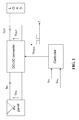
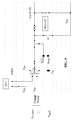
- P&O based MPP trackers are typically implemented by a DSP/ ⁇ C in a feedback loop of a DC-DC converter, whose duty cycle (D) is controlled in such a way as to maximize the power derivable from the PV panel by an electrical load according to a basic scheme as shown in FIG. 1 .
- controlling (varying) the duty cycle of the DC-DC converter is equivalent to perturb the voltage V PV and thus the power extracted from the PV panel.
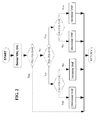
- V PV *I PV The voltage across the PV panel terminals, V PV , and the delivered current, I PV , are periodically measured and converted into digital words. Then their multiplication (V PV *I PV ) is executed to obtain the power currently extracted from the panel and the value obtained is compared with a previously calculated and stored value of output power in order to set the sign of increment of the duty cycle of the PWM drive signal of the power switch of the DC-DC converter that determined the observed variation of the output power. If that variation is greater than zero, the sign is kept unchanged, otherwise it is inverted.
- FIG. 2 The flowchart of such a typical digital MPPT control is depicted in FIG. 2 .
- This control requires two sensors, for measuring both the voltage at the panel terminals and the current, needed for calculate the power currently yielded from the PV panel, and thus two analog to digital conversions are needed too.
- DCM Discontinuous Conduction Mode
- the ADC can represent a crucial part of the whole design, as its resolution strictly relates to circuit complexity and control accuracy.
- a constant current, proportional to the power delivered by the panel(s), to the DC-DC converter charges a capacitor during a first portion of the sampling period and discharges it during a second portion of the sampling period; then, in the third and last portion of the sampling period, the amount of charge left in the capacitor feeds a comparator whose output provides a digital signal indicating whether the power is increasing or decreasing.
- An outstandingly effective novel method of maximum power point tracking (MPPT) in operating a photovoltaic power plant that includes at least a DC-DC converter of the output voltage (V PV ) of a single panel or of a plurality of series-parallel interconnected panels, having a power switch driven by a PWM control signal (V PWM ) of variable duty-cycle (D) generated by a PWM control circuit, in discontinuous conduction mode (DCM) or continuous conduction mode (CCM) depending on the current load of the converter, has now been found, which is implemented by simple low cost analog circuits.
- the method does not require the use of any analog to digital conversion, digital processing or storage and requires only a single voltage sensor, in other words, no dissipative sensing resistance needs to be introduced.
- the method comprises:
- An important embodiment of an analog circuit adapted to force the duty cycle of the PWM drive signal (V PWM ) of the power switch of the DC-DC converter to invert the sign of variation for tracking the maximum power point of functioning of the PV power plant basically comprises:
- the duty cycle D of the power switch of a DC-DC converter is controlled by a Pulse Width Modulated (PWM) driving signal, V PWM .
- PWM Pulse Width Modulated
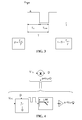
- the ratio between the ON time and the whole period of the waveform is D , as shown in FIG. 3 .
- the amplitude of the PWM driving signal is A and if it is applied to a low-pass filter, the resulting signal will be a constant voltage proportional to the product A*D as far as ripple can be neglected.
- the PWM signal may be used to switch the voltage between V PV and ground at the input of the same low-pass filter, such that the resulting output signal is a constant voltage proportional to V PV *D with negligible ripple.
- the product signal represents the power currently yielded from the PV panel or panels when the converter is functioning in discontinuous conduction mode (DCM).
- FIG. 4 A functional block diagram of hardware adapted to perform such a multiplication is depicted in FIG. 4 .
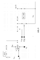
- FIG. 5 is an exemplary analog circuit for producing an output signal of amplitude proportional to the product VPV*D.
- the PWM driving signal is the same waveform that is used to control the power switch of the DC-DC converter of the PV generation plant.
- the low-pass filter may be a simple RC first order circuit, whose time constant may be 5-10 times the period of the PWM driving signal in order to reduce spurious ripple at the output.
- an active low pass filter may alternatively be used.
- V PV may be a scaled version of the panel(s) voltage, tapped from an ordinary voltage divider. Alternatively, and it can be directly coupled, thanks to the decoupling of the amplifier. (V PWM ) and its inverted counterpart are used to switch between V PV and ground the input voltage of the low pass filter. At the output side of the filter, a voltage follower may be used to decouple this stage from the next one.
- the input current is large enough to be monitored as a voltage drop across a relatively small series resistance.
- step-up (boost) converter depicted in FIG. 6 : in (a) for an ideal switch and in (b) for a practical implementation with a MOSFET switch Q 1 in position 1) and a diode D 1 or any equivalent synchronous rectifier in position 2), during the ON time (switch in position 1), the current flowing through the MOSFET Q 1 is I PV (the same current that flows in the PV panel(s)) increases the energy stored in the inductor L . During the OFF time (switch in position 2), the stored energy is released through the diode D 1 to the output node, the voltage on which raises at a value higher than the input voltage.
- I PV the same current that flows in the PV panel(s)
- the MOSFET Q 1 has an intrinsic resistance R DSON when turned on, therefore I PV can be monitored as a voltage drop across Q 1 during ON times.
- I B is equal to the current I A flowing through the MOSFET at T ON l2, as shown in FIG. 7 .
- the average output current can be monitored as the product between (1-D) and the voltage drop across the MOSFET sampled at T ON / 2, which is equal to (R DSON *I A ).
- this multiplication may be performed by a circuit functionally defined in the block diagrams of FIG. 8 .
- the monitored voltage drop must be amplified by a factor K , due to the necessarily low value of R DSON that for a MOSFET is typically in the range of few hundreds m ⁇ .
- FIG. 9 is an exemplary analog circuit for producing an output signal of amplitude proportional to the product of I B* (1-D).
- the circuit may utilize a charge pump at the input for periodically sampling the relatively small voltage drop across the MOSFET at T ON l2 instants accumulating electrical charge for a certain number of PWM cycles for amplifying the detected voltage drop by a certain factor, in the considered sample embodiment by six.
- the resulting voltage, Vcp is proportional to the current I A . of the waveforms of FIG. 7 .
- an analog circuit similar to that of FIG. 5 , performs the product (Vcp*1D).
- the output product signal represents a scaled replica of the average output current of the DC-DC converter I OUT , which tracks the input power trend as explained above.
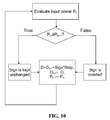
- a simple MPP tracker based on a Perturb & Observe algorithm needs to compare the power extracted from the PV panel at time t n with the power extracted at a precedent time t n-1 in order to verify whether the duty cycle of the PWM signal that controls the power switch of the DC-DC converter is varying in the right direction (i.e. determining an increment of the power extracted from the PV panel(s)) or not. It is assumed that the duty cycle variation is correct if it causes an increase of the input power of the converter, otherwise the duty cycle must vary in the opposite direction.
- FIG. 10 is a typical flow diagram of such a P&O algorithm.
- FIG. 11 An effective embodiment of the core circuit of a fully analog implementation of a MPPT control in a PV generation plant of this disclosure is shown in FIG. 11 .
- the circuit used to delay the product signals produced at the output of the analog circuits of FIG. 5 or of FIG. 9 , that corresponds to the power currently extracted from the panel(s), here identified by the input voltage Vpower may be a distributed RC network, with time constants ranging from about 10 to 100 times the period of the PWM driving signal V PWM .
- the current power value Vpower is applied to the inverting input of a comparator, and its delayed counterpart is applied to the non-inverting input.
- the output of the comparator Vchange becomes high, it means that the direction of the duty cycle variation must be inverted in order to track the maximum power point of operation of the PV panel or panels of the generator plant.
- the number of RC elements in the network will be chosen in order to have the necessary phase shift between the present value of power and its delayed version, sufficient to determine an appreciable voltage drop at the input terminals of the comparator.
- the output of the comparator may be periodically sampled by a common D-type flip flop and the result used to trigger the output inversion of a second flip flop, each time the comparison output Vchange becomes high, that is to say each time the currently monitored power is less than its past value.
- the output of the second flip flop is used to control the slope sign of the reference voltage, Vref, generated by an integrator that is ordinarily compared with a triangular waveform to generate the PWM control waveform.
- a single RC element with a time constant large enough to filter also the lower frequency components introduced by the perturbation process may be used instead of a distributed RC network.
- the time constant should be between about 500 and 1,000 times the period of the PWM drive signal.
- the so filtered value of the input power signal Vpower will correspond to its time-averaged value, which will approach the maximum power when the MPP tracker circuit reaches steady state.
- the time-averaged value of power can be considered as a previous value of power.
- FIG. 12 is a basic block diagram of an exemplary embodiment of the MPPT controller.
- a trivial zero crossing detector can be used to monitor the voltage drop across the diode or any other equivalent synchronous rectifier, and the produced "zero-crossing" flag is processed by any circuit adapted to implement a hysteresis (these ancillary circuits are not shown in the block diagram, being of immediate recognition by any ordinarily skilled technician).
- the DC-DC converter will be considered in DCM only if the flag occurs for at least a pre-established number N of PWM cycles, and it will be considered in CCM if the flag remains absent for at least the same number N of PWM cycles.
- the hysteresis circuit carries out a "working-mode" flag processing that leads to select the pertinent one (Vpower) of the two product signals: V PV *D or Vcp*(1-D), to be fed to the MPP tracker core circuit described above.
- V power the pertinent one
- Vcp*(1-D) the pertinent one of the two product signals: V PV *D or Vcp*(1-D)
- both analog product signals: V PV *D and Vcp*(1-D) are continuously generated by the respective blocks, but only one at the time of the two product signals is used, according to the "working-mode" selection signals CCM and DCM.
- both analog multiplier block include a "memory" element, the capacitor of the output low pass filter, whose state of charge must track the resulting product quantity, in order to guarantee availability of a meaningful analog signal when their output is selected to feed the MPP tracker block.
- another control loop realized by the block Threshold control, forces Vref to stay within a voltage range such that the duty cycle of the PWM generator block be constrained to vary between about 10% and 90%.
- the block PWM generator typically compares the input value Vref with a triangular waveform in order to generate the PWM driving signal V PWM that is used for controlling the step-up converter and the analog multiplication circuits of the blocks V PV *D and Vcp*(1-D).
- the PWM generator block also produces a timing signal that is used at the input of the Charge pump block to sample the voltage drop on the power switch of the converter at T ON / 2 instants.
- circuitry will include other ordinary blocks for functions such as start-up, output voltage and/or current limiting and so on. These circuits not pertinent as far as fully understanding the technical characteristics and manners of practicing the disclosed invention.
Landscapes
- Engineering & Computer Science (AREA)
- Power Engineering (AREA)
- Dc-Dc Converters (AREA)
- Control Of Electrical Variables (AREA)
Abstract
Description
- This disclosure relates in general to photovoltaic panel(s) power plants and in particular to the techniques for maximum power point tracking (briefly MPPT). The disclosed MPPT technique is particularly effective in power plants wherein generated energy is stored in a battery array or is absorbed from the output of a DC-DC step-up converter at an output voltage relatively stable in the short term.
- The cost of photovoltaic (PV) power plants is still high while energy conversion efficiency remains low. Besides the fact that the output power that solar panels can deliver varies with solar radiation, it also depends of how power is being transferred to the load. In other words, solar panels can deliver the maximum power only at specific working points of their V-I characteristics.
- Maximizing the power delivered by PV panels under changing load conditions is a must.
- During the last decades, several methods have been proposed to track the maximum power point of a PV panel array [1], [2], [3]. Most of them are based on a "perturb and observe" (briefly P&O) algorithm usually carried out by either a microcontroller or a DSP [4], [5], [6], [7], [8]. Moreover, only few methods are able to track the MPP using only one sensor [4], [7], [8].
- P&O based MPP trackers are typically implemented by a DSP/µC in a feedback loop of a DC-DC converter, whose duty cycle (D) is controlled in such a way as to maximize the power derivable from the PV panel by an electrical load according to a basic scheme as shown in
FIG. 1 . - In practice, controlling (varying) the duty cycle of the DC-DC converter is equivalent to perturb the voltage VPV and thus the power extracted from the PV panel.
- The voltage across the PV panel terminals, VPV, and the delivered current, IPV, are periodically measured and converted into digital words. Then their multiplication (VPV*IPV) is executed to obtain the power currently extracted from the panel and the value obtained is compared with a previously calculated and stored value of output power in order to set the sign of increment of the duty cycle of the PWM drive signal of the power switch of the DC-DC converter that determined the observed variation of the output power. If that variation is greater than zero, the sign is kept unchanged, otherwise it is inverted. The flowchart of such a typical digital MPPT control is depicted in
FIG. 2 . - This control requires two sensors, for measuring both the voltage at the panel terminals and the current, needed for calculate the power currently yielded from the PV panel, and thus two analog to digital conversions are needed too.
- Furthermore, current measurement implies the connection of a resistance in series between a PV panel terminal and the DC-DC converter and its value is a trade off between conversion efficiency and measurement accuracy. Therefore, current monitoring may become difficult at low power rates, when the current drawn from PV panels is relatively small.
- As interest is in assessing power variation rather than its absolute value, a stable approximation of the current power yield could be used if the DC-DC converter works in the so-called Discontinuous Conduction Mode (DCM), in view of the proportionality that exists between IPV and the duty cycle D in these conditions of operation of the voltage step-up and stabilization DC-DC converter. Therefore, the product between D and VPV can be used as representing approximately the current output power [7], using only one sensor, namely a voltage sensor, which does not require introduction of a series connected resistance that would penalize conversion efficiency.
- Another consideration is that, if the PV generation plant is exploited as a battery charger or in any other equivalent application, including grid connection and alike, where the output voltage of the DC-DC converter can be considered constant in the short term, the input power delivered to the converter by the PV panel, is substantially proportional to the output power (because output/input power ratio of the DC-DC converter can be considered approximately constant) that can be expressed as the product between VOUT (which is considered constant) and the output current IOUT [8]. However, a current sensor is required, which suffers from the above noted drawback of needing a dissipative series resistance. Moreover, an analog to digital conversion (ADC) is needed as well, because of the digital processing (mainly multiplications and power data storage) contemplated by the MPPT control algorithm.
- Notwithstanding the relative simplicity of the digital processing that is required, a working frequency higher than the switching frequency of the DC-DC converter must be provided. Moreover, the ADC can represent a crucial part of the whole design, as its resolution strictly relates to circuit complexity and control accuracy.
- Some P&O based, analog MPP trackers have been disclosed in literature [9], [10]. In these articles, an analog multiplier is used to evaluate the power (VPV*IPV), eliminating the need of analog to digital conversion hardware; however two sensors are needed.
- In [10] a constant current, proportional to the power delivered by the panel(s), to the DC-DC converter, charges a capacitor during a first portion of the sampling period and discharges it during a second portion of the sampling period; then, in the third and last portion of the sampling period, the amount of charge left in the capacitor feeds a comparator whose output provides a digital signal indicating whether the power is increasing or decreasing.
- An outstandingly effective novel method of maximum power point tracking (MPPT) in operating a photovoltaic power plant that includes at least a DC-DC converter of the output voltage (VPV) of a single panel or of a plurality of series-parallel interconnected panels, having a power switch driven by a PWM control signal (VPWM) of variable duty-cycle (D) generated by a PWM control circuit, in discontinuous conduction mode (DCM) or continuous conduction mode (CCM) depending on the current load of the converter, has now been found, which is implemented by simple low cost analog circuits. The method does not require the use of any analog to digital conversion, digital processing or storage and requires only a single voltage sensor, in other words, no dissipative sensing resistance needs to be introduced.
- Basically the method comprises:
- i) detecting, verifying and acknowledging entry in discontinuous conduction mode (DCM) of the DC-DC converter;
- ii) analogically multiplying the current output voltage (VPV) by a quantity corresponding to the time ratio of the current duty-cycle of the PWM drive signal of the converter, for producing an analog signal (VPV*D) that approximately corresponds to the power currently yielded from the panel or panels when the converter is functioning in discontinuous conduction mode (DCM);
- iii) analogically multiplying a periodically sampled, voltage drop (Vmosfet) on the power switch of the converter during conduction phases driven by the PWM drive signal by a predetermined voltage gain factor and low pass filtering the resulting signal for producing an analog product signal (Vcp*(1-D)) that approximately corresponds to the power currently absorbed by an electrical load of the converter when functioning in continuous conduction mode (CCM);
- iv) comparing a first input signal selected between the signals produced in ii) and iii) as representing the currently absorbed power (Vpower) with a second input signal in the form of a delayed replica or a time averaged value of the same signal (Vpower) for outputting a flag (Vchange) when said delayed replica or time averaged value becomes greater than the current value;
- v) inverting the sign of variation of the duty-cycle of said PWM control signal when said delayed replica or a time averaged value becomes greater than the current value.
- An important embodiment of an analog circuit adapted to force the duty cycle of the PWM drive signal (VPWM) of the power switch of the DC-DC converter to invert the sign of variation for tracking the maximum power point of functioning of the PV power plant basically comprises:
- a) means for signalling whether the DC-DC converter is working in discontinuous conduction mode (DCM) or in continuous conduction mode (CCM);
- b) a first analog multiplier circuit of the current output voltage (VPV) by a quantity corresponding to the time ratio of the current duty-cycle (D) of the drive signal of the power switch of converter for producing a signal (VPV*D) representing the current power yielded from the PV panel or panels when the converter is functioning in discontinuous conduction mode (DCM);
- c) a charge pump input stage of a periodically sampled voltage drop (Vmosfet) on the power switch of the converter during conduction phases, for producing an output voltage (Vcp), and a second analog multiplier circuit of the charge pump output voltage (Vcp) by a quantity corresponding to the complementary value (1-D) of said time ratio of the current duty-cycle (D) of the drive signal of the power switch of converter for producing a product signal (Vcp*(1-D)) representing the power currently absorbed by the load of the converter when functioning in continuous conduction mode (CCM);
- d) an analog maximum power tracking circuit core including a comparator of a first input signal (Vpower) selected between the signals produced by b) and c) with a delayed replica or time averaged value of the same signal, for producing an output flag (Vchange) when said delayed replica or time averaged value becomes greater than the current value;
- e) means for inverting the sign of variation of the duty-cycle of said PWM drive signal in controlled by said flag.
-
-
FIG. 1 is a block diagram of a photovoltaic energy conversion system. -
FIG. 2 is a flowchart of a typical digital P&O based MPPT control. -
FIG. 3 is a PWM driving signal waveform. -
FIG. 4 is a block diagram of hardware for obtaining the product VPV*D. -
FIG. 5 is an analog circuit implementation of the functional diagram ofFIG. 4 . -
FIG. 6 depicts basic circuit diagrams of a boost converter: (a) with an ideal switch, (b) with an analog switching device. -
FIG. 7 shows waveforms of (a) input (inductor) current, (b) output diode current, (c) MOSFET switch current. -
FIG. 8 is a block diagram of hardware for obtaining the product IA *(1-D). -
FIG. 9 is an analog circuit implementation of the functional diagram ofFIG. 8 . -
FIG. 10 is a P&O flow diagram of MPPT. -
FIG. 11 is an analog circuit implementation of the MPP tracker. -
FIG. 12 is a basic functional block diagram of an exemplary MPPT controller of this disclosure. - The duty cycle D of the power switch of a DC-DC converter is controlled by a Pulse Width Modulated (PWM) driving signal, VPWM. The ratio between the ON time and the whole period of the waveform is D, as shown in
FIG. 3 . - If the amplitude of the PWM driving signal is A and if it is applied to a low-pass filter, the resulting signal will be a constant voltage proportional to the product A*D as far as ripple can be neglected. Moreover the PWM signal may be used to switch the voltage between VPV and ground at the input of the same low-pass filter, such that the resulting output signal is a constant voltage proportional to VPV*D with negligible ripple. The product signal represents the power currently yielded from the PV panel or panels when the converter is functioning in discontinuous conduction mode (DCM).
- A functional block diagram of hardware adapted to perform such a multiplication is depicted in
FIG. 4 . -
FIG. 5 is an exemplary analog circuit for producing an output signal of amplitude proportional to the product VPV*D. - The PWM driving signal is the same waveform that is used to control the power switch of the DC-DC converter of the PV generation plant.
- The low-pass filter may be a simple RC first order circuit, whose time constant may be 5-10 times the period of the PWM driving signal in order to reduce spurious ripple at the output. Of course an active low pass filter may alternatively be used.
- The amplifier is placed before the input switching circuitry for decoupling reasons, without any effect in respect to the basic diagram of
FIG. 4 . VPV may be a scaled version of the panel(s) voltage, tapped from an ordinary voltage divider. Alternatively, and it can be directly coupled, thanks to the decoupling of the amplifier. (VPWM) and its inverted counterpart are used to switch between VPV and ground the input voltage of the low pass filter. At the output side of the filter, a voltage follower may be used to decouple this stage from the next one. - When the DC-DC converter works in CCM, the input current is large enough to be monitored as a voltage drop across a relatively small series resistance.
- Considering the case of a step-up (boost) converter depicted in
FIG. 6 : in (a) for an ideal switch and in (b) for a practical implementation with a MOSFET switch Q1 in position 1) and a diode D1 or any equivalent synchronous rectifier in position 2), during the ON time (switch in position 1), the current flowing through the MOSFET Q1 is IPV (the same current that flows in the PV panel(s)) increases the energy stored in the inductor L. During the OFF time (switch in position 2), the stored energy is released through the diode D1 to the output node, the voltage on which raises at a value higher than the input voltage. - Of course, the MOSFET Q1 has an intrinsic resistance RDSON when turned on, therefore IPV can be monitored as a voltage drop across Q1 during ON times.
- The average output current is equal to the average current flowing through the diode that is given by the following equation:

where IB is the median current flowing through the diode, as shown inFIG. 7 , valid when the converter works in CCM. - In fact, if the DC-DC converter works in DCM, the diode conduction time will be less than TON because the diode conducts until its current is greater than zero. Thus the above equation holds if TOFF means the effective diode conduction time rather than TON.
- Furthermore IB is equal to the current IA flowing through the MOSFET at TONl2, as shown in
FIG. 7 . Thus the average output current can be monitored as the product between (1-D) and the voltage drop across the MOSFET sampled at TON /2, which is equal to (RDSON*IA). - Similarly to the product (VPV*D), this multiplication may be performed by a circuit functionally defined in the block diagrams of
FIG. 8 . In this case, the monitored voltage drop must be amplified by a factor K, due to the necessarily low value of RDSON that for a MOSFET is typically in the range of few hundreds mΩ. -
FIG. 9 is an exemplary analog circuit for producing an output signal of amplitude proportional to the product of IB*(1-D). - The circuit may utilize a charge pump at the input for periodically sampling the relatively small voltage drop across the MOSFET at TONl2 instants accumulating electrical charge for a certain number of PWM cycles for amplifying the detected voltage drop by a certain factor, in the considered sample embodiment by six. The resulting voltage, Vcp, is proportional to the current IA. of the waveforms of
FIG. 7 , Then an analog circuit, similar to that ofFIG. 5 , performs the product (Vcp*1D). The output product signal represents a scaled replica of the average output current of the DC-DC converter IOUT, which tracks the input power trend as explained above. - A simple MPP tracker based on a Perturb & Observe algorithm needs to compare the power extracted from the PV panel at time tn with the power extracted at a precedent time tn-1 in order to verify whether the duty cycle of the PWM signal that controls the power switch of the DC-DC converter is varying in the right direction (i.e. determining an increment of the power extracted from the PV panel(s)) or not. It is assumed that the duty cycle variation is correct if it causes an increase of the input power of the converter, otherwise the duty cycle must vary in the opposite direction.
FIG. 10 is a typical flow diagram of such a P&O algorithm. - An effective embodiment of the core circuit of a fully analog implementation of a MPPT control in a PV generation plant of this disclosure is shown in
FIG. 11 . The circuit used to delay the product signals produced at the output of the analog circuits ofFIG. 5 or ofFIG. 9 , that corresponds to the power currently extracted from the panel(s), here identified by the input voltage Vpower may be a distributed RC network, with time constants ranging from about 10 to 100 times the period of the PWM driving signal VPWM. The current power value Vpower is applied to the inverting input of a comparator, and its delayed counterpart is applied to the non-inverting input. When the output of the comparator Vchange becomes high, it means that the direction of the duty cycle variation must be inverted in order to track the maximum power point of operation of the PV panel or panels of the generator plant. - The number of RC elements in the network will be chosen in order to have the necessary phase shift between the present value of power and its delayed version, sufficient to determine an appreciable voltage drop at the input terminals of the comparator.
- The output of the comparator may be periodically sampled by a common D-type flip flop and the result used to trigger the output inversion of a second flip flop, each time the comparison output Vchange becomes high, that is to say each time the currently monitored power is less than its past value. The output of the second flip flop is used to control the slope sign of the reference voltage, Vref, generated by an integrator that is ordinarily compared with a triangular waveform to generate the PWM control waveform.
- Optionally, a single RC element with a time constant large enough to filter also the lower frequency components introduced by the perturbation process may be used instead of a distributed RC network. The time constant should be between about 500 and 1,000 times the period of the PWM drive signal. In this case, the so filtered value of the input power signal Vpower will correspond to its time-averaged value, which will approach the maximum power when the MPP tracker circuit reaches steady state. The time-averaged value of power can be considered as a previous value of power.
-
FIG. 12 is a basic block diagram of an exemplary embodiment of the MPPT controller. - A trivial zero crossing detector can be used to monitor the voltage drop across the diode or any other equivalent synchronous rectifier, and the produced "zero-crossing" flag is processed by any circuit adapted to implement a hysteresis (these ancillary circuits are not shown in the block diagram, being of immediate recognition by any ordinarily skilled technician). The DC-DC converter will be considered in DCM only if the flag occurs for at least a pre-established number N of PWM cycles, and it will be considered in CCM if the flag remains absent for at least the same number N of PWM cycles. Thus the hysteresis circuit carries out a "working-mode" flag processing that leads to select the pertinent one (Vpower) of the two product signals: VPV*D or Vcp*(1-D), to be fed to the MPP tracker core circuit described above. Of course, both analog product signals: VPV*D and Vcp*(1-D), are continuously generated by the respective blocks, but only one at the time of the two product signals is used, according to the "working-mode" selection signals CCM and DCM.
- In fact, both analog multiplier block include a "memory" element, the capacitor of the output low pass filter, whose state of charge must track the resulting product quantity, in order to guarantee availability of a meaningful analog signal when their output is selected to feed the MPP tracker block.
- Preferably, as shown in the exemplary diagram of
FIG. 12 , another control loop, realized by the block Threshold control, forces Vref to stay within a voltage range such that the duty cycle of the PWM generator block be constrained to vary between about 10% and 90%. - The block PWM generator typically compares the input value Vref with a triangular waveform in order to generate the PWM driving signal VPWM that is used for controlling the step-up converter and the analog multiplication circuits of the blocks VPV*D and Vcp*(1-D). The PWM generator block also produces a timing signal that is used at the input of the Charge pump block to sample the voltage drop on the power switch of the converter at TON /2 instants.
- Of course, the complete circuitry will include other ordinary blocks for functions such as start-up, output voltage and/or current limiting and so on. These circuits not pertinent as far as fully understanding the technical characteristics and manners of practicing the disclosed invention.
-
- [1] Trishan Esram and Patrick L. Chapman, "Comparison of Photovoltaic Array Maximum Power Point Tracking Techniques ", IEEE transactions on energy conversion, Vol. 22, NO. 2, June 2007.
- [2] N. A. Licia, C. F. Braz, and R. S. Selenio, "Control integrated maximum power point tracking methods ", in Proc. 16th Eur. Photovolt. Solar Energy Conf., May 2000, pp. 2582-2585.
- [3] D. P. Hohm andM. E. Ropp, "Comparative study of maximum power point tracking algorithms", in Proc. Photovolt.: Res. Appl., Apr. 2003, pp. 47-62.
- [4] Ashish Pandey, Nivedita Dasgupta and Ashok K. Mukerjee, "A Simple Single-Sensor MPPT Solution", IEEE transactions on power electronics, Vol. 22, NO. 2, March 2007.
- [5] Dezso Sera , Tamas Kerekes , Remus Teodorescu and Frede Blaabjerg, "Improved MPPT Algorithms for Rapidly Changing Environmental Conditions", Power Electronics and Motion Control Conference, 2006. EPEPEMC 2006. 12th International, Aug. 30 2006-Sept. 1 2006 Page(s):1614 - 1619.
- [6] Chihchiang Hua, Member, IEEE, Jongrong Lin, and Chihming Shen, "Implementation of a DSP-Controlled Photovoltaic System with Peak Power Tracking", IEEE transactions on industrial electronics, Vol. 45, NO. 1, February 1998.
- [7] John Charais, "AN1211 - Maximum Power Solar Converter", Microchip Technology Inc.: Application note DS01211A, 2008.
- [8] Cesare Alippi and Cristian Galperti, "An Adaptive System for Optimal Solar Energy Harvesting in Wireless Sensor Network Nodes ", IEEE Transactions on circuits and systems-i: regular papers, Vol. 55, NO. 6, July 2008.
- [9] R. Leyva, C. Alonso, I. Queinnec, A. Cid-Pastor, D. Lagrange, L. Martinez-Salamero, "MPPT of Photovoltaic Systems using Extremum-Seeking Control", IEEE transactions on aerospace and electronic systems, Vol. 42, NO. 1 January 2006.
- [10] Yongho Kim, Hyunmin Jo, and Deokjung Kim, "A new peak power tracker for cost-effective photovoltaic power system", Energy Conversion Engineering Conference, 1996. IECEC 96. Proceedings of the 31st Intersociety, Volume 3, 11-16 Aug. 1996 Page(s):1673 - 1678 vol.3.
Claims (7)
- A method of maximum power point tracking (MPPT) in a photovoltaic power plant that includes at least a voltage stabilizing DC-DC converter of the output voltage (VPV) of a single or of a plurality of series-parallel connected panels, having a power switch controlled by a PWM drive signal (VPWM) of variable duty-cycle (D) generated by a PWM control circuit, in discontinuous conduction mode (DCM) or continuous conduction mode (CCM) depending on load condition of the converter, comprising the operations ofi) detecting whether the DC-DC converter is functioning in discontinuous conduction mode (DCM) or continuous conduction mode (CCM);ii) analogically multiplying the current voltage at PV panel terminals (VPV) by a quantity corresponding to the time ratio of the current duty-cycle (D) of the PWM drive signal of the converter, for producing an analog product signal (VPV*D) that approximately corresponds to the power currently yielded from the panel or panels when the converter is functioning in discontinuous conduction mode (DCM);iii) analogically multiplying a signal of magnitude representing the voltage drop (Vmosfet) on the power switch of the converter during conduction phases driven by the PWM drive signal, by a predetermined voltage gain factor and low pass filtering the resulting signal for producing an analog product signal (Vcp*(1-D)) that approximately corresponds to the power currently absorbed by an electrical load of the converter when functioning in continuous conduction mode (CCM);iv) comparing a first input signal, selected between the signals produced in ii) and iii) as representing the power currently yielded from the panel or panels, (Vpower) with a second input signal in the form of a delayed replica or of a time averaged value of the same signal (Vpower) for outputting a flag (Vchange) when said delayed replica or time averaged value becomes greater than the current value;v) inverting the sign of variation of the duty-cycle of said PWM control signal when said delayed replica or a time averaged value becomes greater than the current value.
- An analog MPPT circuit for a photovoltaic power plant that includes at least a voltage stabilizing DC-DC converter of the voltage (VPV) at terminals of a single panel or a plurality of series-parallel connected panels, having a power switch driven by a PWM control signal (VPWM) of variable duty-cycle (D) generated by a PWM control circuit, in discontinuous conduction mode (DCM) or continuous conduction mode (CCM) depending on electrical load condition of the converter, comprising:a) means for detecting whether the DC-DC converter is working in discontinuous conduction mode (DCM) or in continuous conduction mode (CCM);b) a first analog multiplier circuit of the current voltage at PV panel terminals (VPV) by a quantity corresponding to the time ratio of the current duty-cycle (D) of the drive signal of the power switch of converter for producing a signal (VPV*D) representing the current power yielded from the PV panel or panels when the converter is functioning in discontinuous conduction mode (DCM);c) a charge pump input stage of a periodically sampled voltage drop (Vmosfet) on the power switch of the converter during conduction phases, for producing an output voltage (Vcp) of cumulative level for a pre-established number of PWM cycles, and a second analog multiplier circuit of the charge pump output voltage (Vcp) by a quantity corresponding to the complementary value (1-D) of said time ratio of the current duty-cycle (D) of the drive signal of the power switch of the converter for producing a product signal (Vcp*(1-D)) representing the power currently absorbed by the load of the converter when functioning in continuous conduction mode (CCM);d) an analog maximum power tracking circuit core including a comparator of a first input signal (Vpower) selected between the signals produced by b) and c) with a second input signal in form of a delayed replica or time averaged value of the same signal (Vpower), for producing an output flag (Vchange) when said delayed replica or time averaged value becomes greater than the current value;e) means for inverting the sign of variation of the duty-cycle of said PWM drive signal in controlled by said flag.
- The analog MPPT circuit of claim 2, wherein said core circuit includes a distributed RC network, with time constants comprised between 10 and 100 times the period of the PWM drive signal, connected to the related input of said comparator for delaying said replica of the selected one (Vpower) of the signals produced by b) or c).
- The analog MPPT circuit of claim 2, wherein said core circuit includes a single RC input circuit, having a time constant comprised between 500 and 1,000 times the period of the PWM drive signal, connected to the related input of said comparator for providing said time averaged value of the selected one (Vpower) same signal of the selected one (Vpower) of the signals produced by b) or c).
- The analog MPPT circuit of claim 2, wherein said converter is a step-up converter using a diode or equivalent synchronous rectifying means, through which energy stored in the reactive element of the converter during ON phases of the power switch transfers to an electrical load of the converter and said a means for flagging said functioning modes comprise a monitoring circuit of the sign of the bias of the converter diode or equivalent synchronous rectifying means, adapted to flag discontinuous conduction mode (DCM) when the diode or other rectifying means are reverse biased during OFF phases of the power switch of the converter, confirming otherwise continuous conduction mode (CCM), and a hysteresis flag processing circuit for validating a discontinuous conduction mode (DCM) recognition when the flag occurs for at least a predefined number of successive PWM cycles or a continuous conduction mode (CCM) recognition when the flag remains absent for at least the same predefined number of successive PWM cycles.
- The analog MPPT circuit of claim 2, further comprising a threshold control circuit for forcing a reference voltage (Vref) to be compared with a triangular waveform in said PWM control circuit, for generating said PWM control signal (VPWM), to remain within a voltage range such to limit the range of variation of the duty-cycle between 10% and 90%.
- The analog MPPT circuit of claim 2, wherein said power switch of the DC-DC converter is a MOSFET.
Applications Claiming Priority (1)
| Application Number | Priority Date | Filing Date | Title |
|---|---|---|---|
| ITVA20090042 | 2009-07-02 |
Publications (2)
| Publication Number | Publication Date |
|---|---|
| EP2290784A2 true EP2290784A2 (en) | 2011-03-02 |
| EP2290784A3 EP2290784A3 (en) | 2012-12-19 |
Family
ID=41607704
Family Applications (1)
| Application Number | Title | Priority Date | Filing Date |
|---|---|---|---|
| EP20100166273 Withdrawn EP2290784A3 (en) | 2009-07-02 | 2010-06-17 | Analogic MPPT circuit for photovoltaic power generation plant |
Country Status (2)
| Country | Link |
|---|---|
| US (1) | US8339112B2 (en) |
| EP (1) | EP2290784A3 (en) |
Cited By (5)
| Publication number | Priority date | Publication date | Assignee | Title |
|---|---|---|---|---|
| TWI481988B (en) * | 2012-04-28 | 2015-04-21 | Au Optronics Corp | Power tracking device and power tracking method |
| CN104731157A (en) * | 2015-03-16 | 2015-06-24 | 北京康拓科技有限公司 | Artificial maximum power judgment circuit |
| CN112003359A (en) * | 2020-07-15 | 2020-11-27 | 宁波大学 | Double-source energy acquisition circuit based on double-stack resonance |
| CN114035644A (en) * | 2021-10-21 | 2022-02-11 | 西安理工大学 | Control method for eliminating steady-state oscillation of photovoltaic power generation system by improving P & O method |
| US11368023B2 (en) | 2018-03-22 | 2022-06-21 | General Electric Company | Dual-sampling maximum power point tracking with dynamic power limiting for power systems |
Families Citing this family (30)
| Publication number | Priority date | Publication date | Assignee | Title |
|---|---|---|---|---|
| FR2961040B1 (en) * | 2010-06-04 | 2012-06-29 | Commissariat Energie Atomique | CONVERTER CIRCUIT AND ELECTRONIC SYSTEM COMPRISING SUCH A CIRCUIT |
| KR20120080107A (en) * | 2011-01-06 | 2012-07-16 | 삼성전자주식회사 | Power control method and apparatus for tracking maximum power point in a photovoltaic system |
| EP2684060A4 (en) * | 2011-03-09 | 2015-06-03 | Solantro Semiconductor Corp | Photovoltaic system maximum power point tracking |
| US9252661B2 (en) * | 2011-04-01 | 2016-02-02 | Qualcomm Inc. | Methods and devices for power supply control |
| JP5842366B2 (en) * | 2011-04-04 | 2016-01-13 | 富士電機株式会社 | Switching power supply control circuit |
| TWI438602B (en) | 2011-12-02 | 2014-05-21 | Ind Tech Res Inst | Maximum power point tracking controllers, maximum power point tracking systems and maximum power point tracking methods |
| CN102447428A (en) * | 2011-12-21 | 2012-05-09 | 东莞市凯登能源科技有限公司 | Method, device and system for self-locking of power |
| CN102427316A (en) * | 2011-12-26 | 2012-04-25 | 东莞市凯登能源科技有限公司 | Power automatic searching method, apparatus thereof and system thereof |
| EP2802955A2 (en) * | 2012-01-11 | 2014-11-19 | Koninklijke Philips N.V. | Solar power converter and method of controlling solar power conversion |
| CN102594211B (en) * | 2012-01-19 | 2014-08-13 | 北京工商大学 | Optimizing method and tracking device for output power of partially shielded photovoltaic power generation system |
| WO2014070831A1 (en) * | 2012-10-30 | 2014-05-08 | Board Of Trustees Of The University Of Alabama | Distributed battery power electronics architecture and control |
| CN103207639B (en) * | 2013-04-10 | 2015-04-01 | 卧龙电气集团股份有限公司 | Photovoltaic inverter with maximum power point tracking module and operation method of photovoltaic inverter |
| CN103218006A (en) * | 2013-04-23 | 2013-07-24 | 南京航空航天大学 | Novel maximum power point tracking (MPPT) control method based on Boost-type convertor |
| TWI470396B (en) | 2013-06-26 | 2015-01-21 | Ind Tech Res Inst | Power point tracking method and apparatus |
| KR101452776B1 (en) * | 2013-07-10 | 2014-12-17 | 엘에스산전 주식회사 | Photovoltaic system |
| GB201312621D0 (en) | 2013-07-15 | 2013-08-28 | Univ Plymouth | Control arrangement |
| US9596724B2 (en) | 2013-08-27 | 2017-03-14 | Texas Instruments Incorporated | Method and apparatus for calculating an average value of an inaccessible current from an accessible current |
| US9397501B2 (en) | 2013-09-09 | 2016-07-19 | Mitsubishi Electric Research Laboratories, Inc. | Maximum power point tracking for photovoltaic power generation system |
| KR20150073680A (en) * | 2013-12-23 | 2015-07-01 | 한국전자통신연구원 | Apparatus and method of tracking maximum power |
| JP6346955B2 (en) * | 2014-01-17 | 2018-06-20 | ユニバーシティ オブ バージニア パテント ファウンデーション ディー/ビー/エイ ユニバーシティ オブ バージニア ライセンシング アンド ベンチャーズ グループUniversity Of Virginia Patent Foundation,D/B/A University Of Virginia Licensing & Ventures Group | Boost converter with peak inductor current control |
| US20150221799A1 (en) * | 2014-01-29 | 2015-08-06 | Nate D. Hawthorn | Transformerless Photovoltaic Solar Heating System |
| CN104868742B (en) * | 2015-05-28 | 2017-07-11 | 西南交通大学 | It is a kind of to realize the virtual power control method that full-bridge isolates DC DC converter decompression transformation pattern minimum current stress |
| CN106329687B (en) * | 2016-08-31 | 2019-08-20 | 天宝电子(惠州)有限公司 | A kind of Portable AC charging pile control circuit |
| US9991715B1 (en) | 2017-03-09 | 2018-06-05 | Industrial Technology Research Institute | Maximum power point tracking method and apparatus |
| TWI632445B (en) * | 2017-03-09 | 2018-08-11 | 財團法人工業技術研究院 | Maximum power point tracking method and apparatus |
| EP3474407B1 (en) * | 2017-10-18 | 2020-01-15 | e-peas S.A. | Power management integrated circuit for energy harvesting with multi power mode selection |
| KR102245969B1 (en) * | 2019-11-21 | 2021-04-29 | 연세대학교 산학협력단 | System and Method for Controlling Constant Power Generation of Photovoltaic System |
| CN110855169B (en) * | 2019-12-06 | 2021-09-14 | 龙岩学院 | Single-phase inverter model prediction control method without voltage sensor |
| CN111404141B (en) * | 2020-03-30 | 2023-04-25 | 湖南大学 | Control method and system for inhibiting output oscillation of photovoltaic converter in direct-current power grid |
| CN114115431B (en) * | 2021-11-30 | 2023-05-30 | 浙江佳乐科仪股份有限公司 | Photovoltaic power generation maximum power tracking method and system |
Family Cites Families (11)
| Publication number | Priority date | Publication date | Assignee | Title |
|---|---|---|---|---|
| JP3744679B2 (en) * | 1998-03-30 | 2006-02-15 | 三洋電機株式会社 | Solar power plant |
| US6043633A (en) * | 1998-06-05 | 2000-03-28 | Systel Development & Industries | Power factor correction method and apparatus |
| US20030066555A1 (en) * | 2000-12-04 | 2003-04-10 | Hui Ron Shu Yuen | Maximum power tracking technique for solar panels |
| FI3589081T3 (en) * | 2004-03-15 | 2024-03-28 | Signify North America Corp | Power control methods and apparatus |
| US7102341B1 (en) * | 2005-03-30 | 2006-09-05 | Texas Instruments Incorporated | Apparatus for controlling a power factor correction converter device |
| ITSA20060016A1 (en) * | 2006-06-07 | 2007-12-08 | Univ Degli Studi Salerno | METHOD AND DEVICE FOR THE FUNCTIONING OF ENERGY SOURCES AT THE MAXIMUM POWER POINT. |
| US7595623B2 (en) * | 2006-11-20 | 2009-09-29 | Freescale Semiconductor, Inc. | Methods and apparatus for a spread spectrum switching regulator |
| JP4374033B2 (en) * | 2007-02-26 | 2009-12-02 | 株式会社ルネサステクノロジ | Switching power supply circuit |
| US8130522B2 (en) * | 2007-06-15 | 2012-03-06 | The Regents Of The University Of Colorado, A Body Corporate | Digital power factor correction |
| US7906943B2 (en) * | 2007-12-20 | 2011-03-15 | Microsemi Corporation | Boost converter with adaptive coil peak current |
| JP4631916B2 (en) * | 2008-02-21 | 2011-02-16 | 日本テキサス・インスツルメンツ株式会社 | Boost DC-DC converter |
-
2010
- 2010-06-17 EP EP20100166273 patent/EP2290784A3/en not_active Withdrawn
- 2010-07-01 US US12/828,736 patent/US8339112B2/en active Active
Non-Patent Citations (9)
| Title |
|---|
| ASHISH PANDEY; NIVEDITA DASGUPTA; ASHOK K. MUKERJEE: "A Simple Single-Sensor MPPT Solution", IEEE TRANSACTIONS ON POWER ELECTRONICS, vol. 22, no. 2, March 2007 (2007-03-01) |
| CESARE ALIPPI; CRISTIAN GALPERTI: "An Adaptive System for Optimal Solar Energy Harvesting in Wireless Sensor Network Nodes", IEEE TRANSACTIONS ON CIRCUITS AND SYSTEMS-I: REGULAR PAPERS, vol. 55, no. 6, July 2008 (2008-07-01) |
| CHIHCHIANG HUA; MEMBER, IEEE; JONGRONG LIN; CHIHMING SHEN: "Implementation of a DSP-Controlled Photovoltaic System with Peak Power Tracking", IEEE TRANSACTIONS ON INDUSTRIAL ELECTRONICS, vol. 45, no. 1, February 1998 (1998-02-01) |
| D. P. HOHM; M. E. ROPP: "Comparative study of maximum power point tracking algorithms", PROC. PHOTOVOLT.: RES. APPL., April 2003 (2003-04-01), pages 47 - 62 |
| DEZSO SERA; TAMAS KEREKES; REMUS TEODORESCU; FREDE BLAABJERG: "Improved MPPT Algorithms for Rapidly Changing Environmental Conditions", POWER ELECTRONICS AND MOTION CONTROL CONFERENCE, 2006. EPEPEMC 2006. 12TH INTERNATIONAL, 30 August 2006 (2006-08-30), pages 1614 - 1619 |
| N. A. LICIA; C. F. BRAZ; R. S. SELENIO: "Control integrated maximum power point tracking methods", PROC. 16TH EUR. PHOTOVOLT. SOLAR ENERGY CONF., May 2000 (2000-05-01), pages 2582 - 2585 |
| R. LEYVA; C. ALONSO; 1. QUEINNEC; A. CID-PASTOR; D. LAGRANGE; L. MARTINEZ-SALAMERO: "MPPT of Photovoltaic Systems using Extremum-Seeking Control", IEEE TRANSACTIONS ON AEROSPACE AND ELECTRONIC SYSTEMS, vol. 42, January 2006 (2006-01-01), pages 1 |
| TRISHAN ESRAM; PATRICK L. CHAPMAN: "Comparison ofPhotovoltaic Array Maximum Power Point Tracking Techniques", IEEE TRANSACTIONS ON ENERGY CONVERSION, vol. 22, no. 2, June 2007 (2007-06-01) |
| YONGHO KIM; HYUNMIN JO; DEOKJUNG KIM: "A new peak power tracker for cost-effective photovoltaic power system", ENERGY CONVERSION ENGINEERING CONFERENCE, 1996. IECEC 96. PROCEEDINGS OF THE 31ST INTERSOCIETY, vol. 3, 11 August 1996 (1996-08-11), pages 1673 - 1678 |
Cited By (6)
| Publication number | Priority date | Publication date | Assignee | Title |
|---|---|---|---|---|
| TWI481988B (en) * | 2012-04-28 | 2015-04-21 | Au Optronics Corp | Power tracking device and power tracking method |
| CN104731157A (en) * | 2015-03-16 | 2015-06-24 | 北京康拓科技有限公司 | Artificial maximum power judgment circuit |
| US11368023B2 (en) | 2018-03-22 | 2022-06-21 | General Electric Company | Dual-sampling maximum power point tracking with dynamic power limiting for power systems |
| CN112003359A (en) * | 2020-07-15 | 2020-11-27 | 宁波大学 | Double-source energy acquisition circuit based on double-stack resonance |
| CN114035644A (en) * | 2021-10-21 | 2022-02-11 | 西安理工大学 | Control method for eliminating steady-state oscillation of photovoltaic power generation system by improving P & O method |
| CN114035644B (en) * | 2021-10-21 | 2023-07-11 | 西安理工大学 | Control method for eliminating steady-state oscillation of photovoltaic power generation system by improving P & O method |
Also Published As
| Publication number | Publication date |
|---|---|
| US8339112B2 (en) | 2012-12-25 |
| EP2290784A3 (en) | 2012-12-19 |
| US20110001360A1 (en) | 2011-01-06 |
Similar Documents
| Publication | Publication Date | Title |
|---|---|---|
| US8339112B2 (en) | Analog MPPT circuit for photovoltaic power plant | |
| US8422258B2 (en) | Maximum power point tracker, power conversion controller, power conversion device having insulating structure, and method for tracking maximum power point thereof | |
| EP3010135B1 (en) | Inverter device | |
| US8400134B2 (en) | Apparatus and methodology for maximum power point tracking for a solar panel | |
| TWI451676B (en) | Dc power conversion module, control method thereof, junction box and power harvesting system | |
| EP3010136B1 (en) | Inverter device | |
| US8035257B2 (en) | Method and apparatus for improved burst mode during power conversion | |
| JP5455184B2 (en) | Method and apparatus for power conversion using maximum power point tracking and burst mode functions | |
| JP4491622B2 (en) | Solar power plant | |
| EP2610698A1 (en) | Solar power generation system, control device used for solar power generation system, and control method and program for the same | |
| US9000748B2 (en) | Maximum power point tracking controllers and maximum power point tracking methods | |
| US20160197508A1 (en) | Maximum Power Point Tracking in Energy Harvesting DC-to-DC Converter | |
| CN109428545B (en) | Method for switching power optimizer of photovoltaic module between different working modes | |
| CN102156504A (en) | Solar-cell panel maximum power tracking device, tracking method and solar power supply device using the same | |
| JP2004280220A (en) | Solar power generation system and maximum power point follow-up control method | |
| KR102087063B1 (en) | Method and apparatus for improved burst mode during power conversion | |
| Kabalci et al. | Design and implementation of a PI-MPPT based Buck-Boost converter | |
| CN102622022A (en) | Voltage controlled current source for voltage regulation | |
| CN109428544B (en) | Switching method for realizing access or removal of photovoltaic module in battery string group | |
| CN113252974B (en) | Load current detection circuit | |
| CN102012714B (en) | Tracking method and circuit of maximum power of solar panel | |
| Riawan et al. | Analysis and design of a solar charge controller using cuk converter | |
| CN102742136B (en) | Buck dc-dc and ON-OFF control circuit | |
| CN103995561A (en) | Maximum power point tracing method and device | |
| Kim et al. | A maximum power point tracking circuit of thermoelectric generators without digital controllers |
Legal Events
| Date | Code | Title | Description |
|---|---|---|---|
| PUAI | Public reference made under article 153(3) epc to a published international application that has entered the european phase |
Free format text: ORIGINAL CODE: 0009012 |
|
| AK | Designated contracting states |
Kind code of ref document: A2 Designated state(s): AL AT BE BG CH CY CZ DE DK EE ES FI FR GB GR HR HU IE IS IT LI LT LU LV MC MK MT NL NO PL PT RO SE SI SK SM TR |
|
| AX | Request for extension of the european patent |
Extension state: BA ME RS |
|
| RAP1 | Party data changed (applicant data changed or rights of an application transferred) |
Owner name: STMICROELECTRONICS SRL |
|
| PUAL | Search report despatched |
Free format text: ORIGINAL CODE: 0009013 |
|
| AK | Designated contracting states |
Kind code of ref document: A3 Designated state(s): AL AT BE BG CH CY CZ DE DK EE ES FI FR GB GR HR HU IE IS IT LI LT LU LV MC MK MT NL NO PL PT RO SE SI SK SM TR |
|
| AX | Request for extension of the european patent |
Extension state: BA ME RS |
|
| RIC1 | Information provided on ipc code assigned before grant |
Ipc: G05F 1/67 20060101ALI20121113BHEP Ipc: H02J 7/35 20060101AFI20121113BHEP |
|
| STAA | Information on the status of an ep patent application or granted ep patent |
Free format text: STATUS: THE APPLICATION HAS BEEN WITHDRAWN |
|
| 18W | Application withdrawn |
Effective date: 20130215 |