EP2288089A1 - Data communication system, router, data transmission and mobility management method - Google Patents
Data communication system, router, data transmission and mobility management method Download PDFInfo
- Publication number
- EP2288089A1 EP2288089A1 EP09828565A EP09828565A EP2288089A1 EP 2288089 A1 EP2288089 A1 EP 2288089A1 EP 09828565 A EP09828565 A EP 09828565A EP 09828565 A EP09828565 A EP 09828565A EP 2288089 A1 EP2288089 A1 EP 2288089A1
- Authority
- EP
- European Patent Office
- Prior art keywords
- data
- module
- abr
- mapping information
- information base
- Prior art date
- Legal status (The legal status is an assumption and is not a legal conclusion. Google has not performed a legal analysis and makes no representation as to the accuracy of the status listed.)
- Withdrawn
Links
Images


Classifications
-
- H—ELECTRICITY
- H04—ELECTRIC COMMUNICATION TECHNIQUE
- H04L—TRANSMISSION OF DIGITAL INFORMATION, e.g. TELEGRAPHIC COMMUNICATION
- H04L45/00—Routing or path finding of packets in data switching networks
- H04L45/02—Topology update or discovery
- H04L45/025—Updating only a limited number of routers, e.g. fish-eye update
-
- H—ELECTRICITY
- H04—ELECTRIC COMMUNICATION TECHNIQUE
- H04L—TRANSMISSION OF DIGITAL INFORMATION, e.g. TELEGRAPHIC COMMUNICATION
- H04L45/00—Routing or path finding of packets in data switching networks
- H04L45/02—Topology update or discovery
- H04L45/04—Interdomain routing, e.g. hierarchical routing
-
- H—ELECTRICITY
- H04—ELECTRIC COMMUNICATION TECHNIQUE
- H04L—TRANSMISSION OF DIGITAL INFORMATION, e.g. TELEGRAPHIC COMMUNICATION
- H04L61/00—Network arrangements, protocols or services for addressing or naming
- H04L61/09—Mapping addresses
- H04L61/25—Mapping addresses of the same type
- H04L61/2503—Translation of Internet protocol [IP] addresses
-
- H—ELECTRICITY
- H04—ELECTRIC COMMUNICATION TECHNIQUE
- H04W—WIRELESS COMMUNICATION NETWORKS
- H04W40/00—Communication routing or communication path finding
- H04W40/34—Modification of an existing route
- H04W40/36—Modification of an existing route due to handover
-
- H—ELECTRICITY
- H04—ELECTRIC COMMUNICATION TECHNIQUE
- H04W—WIRELESS COMMUNICATION NETWORKS
- H04W76/00—Connection management
- H04W76/10—Connection setup
-
- H—ELECTRICITY
- H04—ELECTRIC COMMUNICATION TECHNIQUE
- H04W—WIRELESS COMMUNICATION NETWORKS
- H04W8/00—Network data management
- H04W8/26—Network addressing or numbering for mobility support
Definitions
- This application relates to the field of communications, and in particular, a system for data communications, a router, and a method for data transmission and mobility management.
- the routing and addressing architectures are based on IP address space only, and the data routing and session are identified with the same IP address. This limits the scalability of the Internet and results in complicated mobility management.
- the academic and industrial sectors generally believe that separating the identifier (ID) and locator of a node will help address many problems facing the Internet.
- the problems to be solved by the present invention are to provide a system for data communications, an access router (AR), an area border router (ABR), and a method for data transmission, and to transmit terminal data by separating the ID and locator of the terminal.
- a system for data communications is provided to transmit the terminal data that takes IDs as the source and destination addresses.
- the system includes at least one of:
- an access router which includes:
- an area border router which includes:
- a method for data transmission which includes:
- a method for terminal mobility management which includes:
- a method for terminal mobility management which includes:
- the embodiments of the present invention completely separate the ID, LL, and GL of the terminal, and thus solve the problems with the routing table expansion and scalability faced by the Internet. In this way, the terminal data can be transmitted without changing the terminal or the routing protocol stack.
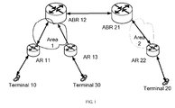
- FIG. 1 shows an architecture of a system for data communications according to an embodiment of the present invention.
- a system for data communications includes at least one AR and at least one ABR.
- the IDs and locators are separated, and the network is divided into multiple areas.
- the AR and ABR use LLs for intra-area communications; the ABR uses the GL for inter-area communications.
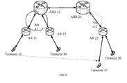
- the system for data communications provided in this embodiment includes AR 11, ABR 12, AR 13, ABR 21, and AR 22.
- AR 11, AR 13, and ABR 12 are in area 1 and are used for managing the data transmission by the terminals in area 1 (terminal 10 and terminal 30); AR 22 and ABR 21 are in area 2 and are used for managing the data transmission by the terminal in area 2 (terminal 20).
- each AR in this embodiment is configured with an LL for establishing communications links to the devices within the area.
- the AR queries the transmission route in the local mapping information base according to the destination ID of the data and then transmits the received data.
- the local mapping information base stores the mappings between IDs and LLs.
- each ABR (ABR 12 or ABR 21) is configured with a GL for establishing communications links to the devices outside the area and an LL for establishing communications links to the devices within the area.
- the ABR queries the transmission route in the local or global mapping information base according to the destination ID of the data and then transmits the data.
- the global mapping information base stores the mappings between IDs and GLs.
- the LLs and GLs can be existing IPv4/IPv6 addresses.
- the AR in the system for data communications of the embodiment includes:
- the AR in this embodiment may further includes an information updating module, adapted to: update the local mapping information base and notify the ABR in the same area of the update results when the terminal enters or leaves the management area of the AR. For example, when terminal 10 in FIG. 1 leaves the management area of AR 11 and enters the management area of AR 13, AR 11 updates the local mapping information base and notifies ABR 12 in the same area of the update results.
- an information updating module adapted to: update the local mapping information base and notify the ABR in the same area of the update results when the terminal enters or leaves the management area of the AR. For example, when terminal 10 in FIG. 1 leaves the management area of AR 11 and enters the management area of AR 13, AR 11 updates the local mapping information base and notifies ABR 12 in the same area of the update results.
- the ABR (ABR 12 or ABR 21) includes:
- the ABR in this embodiment may further includes an information updating module, adapted to: update the global or local mapping information base when the terminal enters or leaves the management area of the ABR.
- the system for data communications accordign to this embodiment includes at least one AR and at least one ABR.
- the system for data communications provided in other embodiments of the present invention further includes at least one of: a local mapping information storage device, adapted to: store the local mapping information base; and a global mapping information storage device, adapted to: store the global mapping information base.
- the AR and ABR queries the local or global mapping information base to identify the route for transmitting the data.
- the embodiments of the present invention completely separate the ID, LL, and GL of the terminal, and thus solve the problems with the routing table expansion and scalability faced by the Internet.
- the terminal data can be transmitted without changing the terminal or the routing protocol stack.
- the hierarchical mapping helps reduces the amount of locally and globally stored information, and thus accelerating the query.
- a method for data transmission based on the preceding system for data communications is provided in the embodiments of the present invention. The following describes the method in this embodiment based on FIG. 4 to FIG. 9 .
- FIG. 4 is a flowchart of a method for data transmission based on the preceding system for data communications according to an embodiment of the present invention.
- the embodiment provides a method for transmitting data between the terminals within the same area. As shown in FIG. 4 , the method includes:
- terminal 10 uses the ID of terminal 10 (ID1) as the source address and the ID of terminal 30 (ID3) as the destination address.
- AR 11 in area 1 finds that the link to terminal 30 is not managed by itself after receiving data from terminal 10, AR 11 checks, by taking the ID3 of terminal 30 as the index, the local mapping information base for the LL of AR 13 that maps the ID3 of terminal 30. Therefore, AR 11 transmits the data to AR 13 through the communications link to AR 13; namely, an IP link encapsulation is added to the outer layer of the original data for transmitting the data, with the source address of the IP link encapsulation being the LL of AR 11 and the destination address being the LL of AR 13.
- AR 13 After receiving the data, AR 13 removes the IP link encapsulation from the outer layer, and then directly transmits the data to terminal 30.
- Terminal 30 can directly return data to terminal 10 and terminal 10 can directly return data to the terminal 20 both based on the information temporarily stored in the router, without querying the route.
- FIG. 5 is a flowchart of a method for data transmission based on the preceding system for data communications according to another embodiment of the present invention.
- the embodiment provides a method for transmitting data between terminals within different areas. As shown in FIG. 5 , the method includes:
- terminal 10 When transmiting data to terminal 20, terminal 10 uses the ID of terminal 10 (ID1) as the source address and the ID of terminal 20 (ID2) as the destination address.
- AR 11 in area 1 finds that the link to terminal 30 is not managed by itself after receiving data from terminal 10, AR 11 checks, by taking the ID2 of terminal 20 as the index, the local mapping information base for the LL that maps the ID2 of terminal 20. AR 11 fails to obtain the LL that maps the ID of terminal 20, so it knows that terminal 20 is not within the local area.
- AR 11 transmits the packets to ABR 12 in the same area through the communications link to ABR 12; namely, an IP link encapsulation is added to the outer layer of the original packet for transmitting the data, with the source addresses of the IP link encapsulation being the LL of AR 11 and the destination address being the LL of ABR 12.
- ABR 12 After receiving the data, ABR 12 removes the IP link encapsulation from the header, queries the global mapping information base by taking the ID2 of terminal 20 as the index, and finds that the GL that maps terminal 20 is managed by ABR 21.
- ABR 12 transmits the data to ABR 21 through an IP link, with the source address of the IP link encapsulation being the GL of ABR 12 and the destination address being the GL of ABR 21.
- ABR 21 After receiving the data, ABR 21 removes the IP link encapsulation from the data, and queries the local mapping information base by taking ID2 as the index. After finding that ID2 maps the LL of AR 22, ABR 21 transmits the data to AR 22 through an IP link, with the source address of the IP link encapsulation being the LL of ABR 21 and the destination address being the LL of AR 22.
- AR 22 After receiving the data, AR 22 removes the IP link encapsulation from the outer layer, and then directly transmits the data to terminal 20.
- Terminal 30 can directly return data to terminal 20 and terminal 10 can directly return data to terminal 20 both based on the information temporarily stored in the router, without querying the route.
- FIG. 6 is a flowchart of a method for data transmission based on the preceding system for data communications accordng to another embodiment of the present invention.
- the method in this embodiment is used to ensure the continuity of data transmission when either of the terminals moves within the area after a data transmission tunnel is established between the terminals.
- the method in this embodiment includes:
- the subsequent data of the terminal (the data to be transmitted to or by the terminal) can be directly transmitted through the tunnel, without querying the information base.
- the method includes:
- the communiation traffic between terminal 10 and terminal 20 can be transmitted through the bi-directional link between AR 11 and AR 13.
- AR 13 and ABR 12 establish a communications link in between by using the LLs as the communications addresses, to replace the communications link between the fifth AR and the first AR for transmitting and receiving data for the terminal. After that, the subsequent data received by terminal 10 can be directly transmitted to AR 13 through ABR 12 instead of AR 11.
- FIG. 8 is a flowchart of a method for data transmission based on the preceding system for data communications according to another embodiment of the present invention.
- the method in this embodiment is used to ensure the continuity of data transmission when either of the terminals moves to a different area after a data transmission tunnel is established between the terminals.
- the method in this embodiment includes:
- the subsequent data of the terminal (the data to be transmitted to or by the terminal) can be directly transmitted through the tunnel, without querying the information base.
- the method includes:
- the communications traffic between terminal 10 and terminal 20 can be transmitted through the bi-directional link between ABR 12 and ABR 21.
- ABR 12 responds to the link establishment request from ABR 21 to establish the link, ABR 12 notifies ABR 21 of the current ID of terminal 10 (the mapping between ID 1 and the GL of ABR 21); and then, ABR 21 directly transmits the data from terminal 20 to terminal 10.
- the embodiments of the present invention completely separate the ID, LL, and GL of the terminal, and thus solve the problems with the routing table expansion and scalability faced by the Internet.
- the terminal data can be transmitted without changing the terminal or the routing protocol stack.
- the hierarchical mapping helps reduces the amount of locally and globally stored information, and thus accelerating the query.
Landscapes
- Engineering & Computer Science (AREA)
- Computer Networks & Wireless Communication (AREA)
- Signal Processing (AREA)
- Data Exchanges In Wide-Area Networks (AREA)
Abstract
Description
- This application relates to the field of communications, and in particular, a system for data communications, a router, and a method for data transmission and mobility management.
- In the traditional Internet, the routing and addressing architectures are based on IP address space only, and the data routing and session are identified with the same IP address. This limits the scalability of the Internet and results in complicated mobility management. After years of discussion, the academic and industrial sectors generally believe that separating the identifier (ID) and locator of a node will help address many problems facing the Internet.
- Currently, many solutions have been launched in the sector by separating the ID and locator of a terminal (e.g., a node). With different features and focuses, these solutions do not treat the network as a whole, and thus vary significantly in the implementation mode. Currently, none of the solutions is accepted as practical.
- The problems to be solved by the present invention are to provide a system for data communications, an access router (AR), an area border router (ABR), and a method for data transmission, and to transmit terminal data by separating the ID and locator of the terminal.
- According to the first aspect of the present invention a system for data communications is provided to transmit the terminal data that takes IDs as the source and destination addresses. The system includes at least one of:
- an AR, adapted to: set local locators (LLs), establish communications links to the devices within the area by using the set LLs, and transmit the received data through the transmission routes, which are obtained by querying the mappings between IDs and LLs in the local mapping information base according to the destination ID of the received data; and
- an ABR, adapted to: set global locators (GLs) and LLs, establish communications links to the devices outside the area by using the set GLs, establish communications links to the devices within the area by using the set LLs, and transmit the received data through the transmission routes, which are obtained by querying the mappings between IDs and GLs in the global mapping information base according to the destination ID of the received data.
- According to the second aspect of the present invention an access router (AR) is provided which includes:
- a configuration module, adapted to: set an LL as the intra-area communications address of the AR;
- a link establishment module, adapted to: establish the communications links to the devices within the area by using the set LL;
- a receiving module, adapted to: receive the data;
- a query module, adapted to: query whether an LL that maps the destination ID of the data received by the receiving exists in the local mapping information base;
- a route identifying module, adapted to: identify the route for transmitting the received data based on the results of querying the local mapping information base by the query module; and
- a transmission module, adapted to: transmit the received data through the transmission route identified by the route identifying module and the link established by the link establishment module.
- According to the third aspect of the present invention an area border router (ABR) is provided which includes:
- a configuration module, adapted to: set a GL as the inter-area communications address and an LL as the intra-area communications address;
- a link establishment module, adapted to: establish the communications links to the devices outside the area by using the set GL, and establish the communications links to the devices within the area by using the set LL;
- a receiving module, adapted to: receive the data;
- a query module, adapted to: query whether an LL that maps the destination ID of the data received by the receiving module exists in the local mapping information base, or query whether a GL that maps the destination ID of the data received by the receiving module exists in the global mapping information base;
- a route identifying module, adapted to: identify the route for transmitting the received data based on the results of querying the local or global mapping information base by the query module; and
- a transmission module, adapted to: transmit the received data through the transmission route identified by the route identifying module and the link established by the link establishment module.
- According to the fourth aspect of the present invention a method for data transmission is provided which includes:
- receiving, by the first AR, the data;
- identifying the transmission route based on the results of querying the local mapping information base; and
- transmitting data, wherein the local mapping information base stores the mappings between IDs and LLs.
- According to the fifth aspect of the present invention a method for terminal mobility management is provided which includes:
- moving, by the terminal, from the management area of the initial AR to that of the current AR in the same area; and
- establishing a communications link between the current and initial ARs, by using the LLs as the communications addresses, for transmitting data of the terminal.
- According to the sixth aspect of the present invention a method for terminal mobility management is provided which includes:
- establishing a communications link between the current and initial ABRs, by using the GLs as the communications addresses, for transmitting data of the terminal, when the terminal moves from the management area of the initial ABR to that of the current ABR.
- The embodiments of the present invention completely separate the ID, LL, and GL of the terminal, and thus solve the problems with the routing table expansion and scalability faced by the Internet. In this way, the terminal data can be transmitted without changing the terminal or the routing protocol stack.
- To describe the technical solutions in the embodiments of the present invention or in the prior art more clearly, the following outlines the accompanying drawings for illustrating such technical solutions. Apparently, the accompanying drawings outlined below are some embodiments of the present invention, and those skilled in the art can derive other drawings from such accompanying drawings without creative efforts.
-
FIG. 1 shows an architecture of a system for data communications according to an embodiment of the present invention; -
FIG. 2 shows a structure of an AR in a system for data communications according to an embodiment of the present invention; -
FIG. 3 shows a structure of an ABR in a system for data communications according to an embodiment of the present invention; -
FIG. 4 is a flowchart of a method for data transmission according to an embodiment of the present invention; -
FIG. 5 is a flowchart of a method for data transmission according to another embodiment of the present invention; -
FIG. 6 is a flowchart of a method for data transmission according to another embodiment of the present invention; -
FIG. 7 shows another architecture of a system for data communications according to an embodiment of the present invention when a terminal moves within the same area; -
FIG. 8 is a flowchart of a method for data transmission according to another embodiment of the present invention; and -
FIG. 9 shows another architecture of a system for data communications according to an embodiment of the present invention when a terminal moves within the same area. - The technical solutions in the embodiments of the present invention are described below clearly and completely with reference to the accompanying drawings in the embodiments of the present invention. Apparently, the described embodiments are merely some of the embodiments of the present invention, rather than all of the embodiments. Based on the embodiments of the present invention, those skilled in the art can obtain other embodiments without making creative efforts, which all fall within the scope of the present invention.
-
FIG. 1 shows an architecture of a system for data communications according to an embodiment of the present invention. In practice, a system for data communications includes at least one AR and at least one ABR. In the architecture used in the embodiments of the present invention, the IDs and locators are separated, and the network is divided into multiple areas. The AR and ABR use LLs for intra-area communications; the ABR uses the GL for inter-area communications. As shown inFIG. 1 , the system for data communications provided in this embodiment includesAR 11, ABR 12,AR 13, ABR 21, andAR 22.AR 11,AR 13, and ABR 12 are inarea 1 and are used for managing the data transmission by the terminals in area 1 (terminal 10 and terminal 30);AR 22 and ABR 21 are inarea 2 and are used for managing the data transmission by the terminal in area 2 (terminal 20). Specifically, in addition to the basic functions, each AR in this embodiment (AR 11,AR 13, or AR 22) is configured with an LL for establishing communications links to the devices within the area. After receiving data, the AR queries the transmission route in the local mapping information base according to the destination ID of the data and then transmits the received data. The local mapping information base stores the mappings between IDs and LLs. In addition to the basic functions, each ABR (ABR 12 or ABR 21) is configured with a GL for establishing communications links to the devices outside the area and an LL for establishing communications links to the devices within the area. After receiving data, the ABR queries the transmission route in the local or global mapping information base according to the destination ID of the data and then transmits the data. The global mapping information base stores the mappings between IDs and GLs. In practice, the LLs and GLs can be existing IPv4/IPv6 addresses. - Further, as shown in
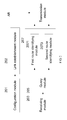
FIG. 2 , the AR (AR 11,AR 13, or AR22) in the system for data communications of the embodiment includes: - a
configuration module 201, adapted to: configure an LL as the intra-area communication address of the AR; - a
link establishment module 202, adapted to: configure the LL for establishing communications links to the devices within the area (for example,AR 11 inFIG. 1 can establish communications links toterminal 10,ABR 12, and ABR 21); - a
receiving module 203, adapted to: receive the data; in practice, receivingmodule 203 receives data from terminal (for example,AR 11 inFIG. 1 can receive data from terminal 10), an ABR in the same area (for example,AR 11 inFIG. 1 can receive fromABR 12 the data to be sent to terminal 10 from area 2), and a different AR in the same area (for example,AR 11 inFIG. 1 can receive data from AR 13); - a
query module 205, adapted to: query whether an LL that maps the destination ID of the data received by receivingmodule 203 exists in the local mapping information base; - a
route identifying module 207, adapted to: identify the route for transmitting the received data based on the results of querying the local mapping information base by thequery module 205; specifically, theroute identifying module 207 further includes: a firstroute identifying module 2071, adapted to: determine to transmit the data to the AR that maps the LL if thequery module 205 obtains the LL that maps the ID of the data in the local mapping information base; a secondroute identifying module 2073, adapted to: determine to transmit the data to the ABR that is bound to the AR in the same area if thequery module 205 does not identify an LL that maps the ID of the data in the local mapping information base; and - a transmission module 209, adapted to: transmit the received data through the transmission route identified by the
route identifying module 207 and the link established by the link establishment module. Specifically, after the route identifying module determines to transmit the data to the AR that maps the identified LL, the transmission module 209 transmits the data through the communiction link to the AR. For example, if theroute identifying module 207 ofAR 11 determines to transmit the data to the identified LL ofAR 13, the transmission module 209 transmits the data toAR 13, with the source address being the LL ofAR 11 and the destination address being the LL ofAR 13. If theroute identifying module 207 does not identify the ID of the data in the local mapping information base, the transmission module 209 transmits the data to the boundABR 12 through a communications link, with the source address being the LL ofAR 11 and the destination address being the LL ofABR 12. - Further, the AR in this embodiment may further includes an information updating module, adapted to: update the local mapping information base and notify the ABR in the same area of the update results when the terminal enters or leaves the management area of the AR. For example, when terminal 10 in
FIG. 1 leaves the management area ofAR 11 and enters the management area ofAR 13,AR 11 updates the local mapping information base and notifiesABR 12 in the same area of the update results. - As shown in
FIG. 3 , the ABR (ABR 12 or ABR 21) includes: - a
configuration module 301, adapted to: configure a GL as the inter-area communications address and an LL as the intra-area communications address; - a
link establishment module 302, adapted to: establish communications links to the devices outside the area by using the configured GL as the communications address, and establish communications links to the devices within the area by using the configured LL as the communications address; for example,ABR 12 inFIG. 1 establishes communications links toAR 11 andAR 13 by using the LL and establishes communications links to ABR 21 by using the GL; - a
receiving module 303, adapted to: receive the data; in practice, the ABR can receive data from the AR in the same area (For example,ABR 12 inFIG. 1 can receive data from AR 11) or the ABR in a different area (For example,ABR 12 inarea 1 inFIG. 1 can receive data fromABR 21 in area 2); - a
query module 305, adapted to: query whether an LL that maps the destination ID of the data received by receivingmodule 303 exists in the local mapping information base, or query whether a GL that maps the destination of the data received exists in the global mapping information base; - a
route identifying module 307, adapted to: identify the route for transmitting the received data based on the results of querying the local or global mapping information base byquery module 305; specifically, theroute identifying module 307 further includes: - a first
route identifying module 3071, adapted to: determine to transmit the data to the AR that maps the LL if thequery module 305 obtains the LL that maps the destination ID of the data in the local mapping information base; for example, if thequery module 305 ofABR 12 inFIG. 1 obtains the LL that maps the destination ID of the received data (for example, LL of AR 11) in the local mapping information base, theroute identifying module 307 can determine to transmit the data toAR 12; and - a second
route identifying module 3073, adapted to: determine to transmit the data to the ABR that maps the identified GL if thequery module 305 obtains the GL that maps the ID of the data in the global mapping information base. For example, if thequery module 305 ofABR 12 inFIG. 1 obtains the GL that maps the destination ID of the received data (for example, GL in ABR 21) in the global mapping information base, theroute identifying module 3073 can determine to transmit the data to ABR 21, with the source address being the GL ofABR 12; and - a transmission module 309, adapted to: transmit the received data through the transmission route identified by the
route identifying module 307 and the link established by the link establishment module. For example, if theroute identifying module 307 determines to transmit the data to the AR that maps the identified LL, the transmission module 309 transmits the data to the AR. Specifically, the ifroute identifying module 307 determines to transmit the data toAR 11, the transmission module 309 ofABR 12 transmits the data toAR 11, with the source address being the LL ofABR 12 and the destination address being the LL ofAR 11. - Further, the ABR in this embodiment may further includes an information updating module, adapted to: update the global or local mapping information base when the terminal enters or leaves the management area of the ABR.
- The ABR in this embodiment may further includes at least one of:
- a local mapping information storage module, adapted to: store the local mapping information base; and
- a global mapping informaiton storage module, adapted to: store the global mapping information base.
- The system for data communications accordign to this embodiment includes at least one AR and at least one ABR. However, in addition to the AR and ABR, the system for data communications provided in other embodiments of the present invention further includes at least one of: a local mapping information storage device, adapted to: store the local mapping information base; and a global mapping information storage device, adapted to: store the global mapping information base. The AR and ABR queries the local or global mapping information base to identify the route for transmitting the data.
- The embodiments of the present invention completely separate the ID, LL, and GL of the terminal, and thus solve the problems with the routing table expansion and scalability faced by the Internet. In this way, the terminal data can be transmitted without changing the terminal or the routing protocol stack. In addition, the hierarchical mapping helps reduces the amount of locally and globally stored information, and thus accelerating the query.
- A method for data transmission based on the preceding system for data communications is provided in the embodiments of the present invention. The following describes the method in this embodiment based on
FIG. 4 to FIG. 9 . -
FIG. 4 is a flowchart of a method for data transmission based on the preceding system for data communications according to an embodiment of the present invention. The embodiment provides a method for transmitting data between the terminals within the same area. As shown inFIG. 4 , the method includes: - S400: Receive by the first AR the data transmitted by the terminal that takes IDs as the source and destination addresses.
- S402: Query whether the LL that maps the destination ID of the received data exists in the local mapping information base, and, after obtaining the LL, determine to transmit the data to the third AR that maps the LL.
- S404: Transmit the data through the communications link by using the LL of the first AR as the source address and the LL of the third AR as the destination address.
- In practice, after a data transmission route is established between two terminals in the preceding embodiment, it is not necessary to query the route for the subsequent data transmission between the terminals, and the subsequent data can be directly transmitted according to the information temporarily stored by the router.
- The following describes the method in this embodiment based on
FIG. 1 . - When transmitting data to
terminal 30, terminal 10 uses the ID of terminal 10 (ID1) as the source address and the ID of terminal 30 (ID3) as the destination address. - If
AR 11 inarea 1 finds that the link toterminal 30 is not managed by itself after receiving data fromterminal 10,AR 11 checks, by taking the ID3 ofterminal 30 as the index, the local mapping information base for the LL ofAR 13 that maps the ID3 ofterminal 30. Therefore,AR 11 transmits the data toAR 13 through the communications link toAR 13; namely, an IP link encapsulation is added to the outer layer of the original data for transmitting the data, with the source address of the IP link encapsulation being the LL ofAR 11 and the destination address being the LL ofAR 13. - After receiving the data,
AR 13 removes the IP link encapsulation from the outer layer, and then directly transmits the data toterminal 30. -
Terminal 30 can directly return data toterminal 10 and terminal 10 can directly return data to the terminal 20 both based on the information temporarily stored in the router, without querying the route. -
FIG. 5 is a flowchart of a method for data transmission based on the preceding system for data communications according to another embodiment of the present invention. The embodiment provides a method for transmitting data between terminals within different areas. As shown inFIG. 5 , the method includes: - S500: Receive by the first AR the data transmitted by the terminal that takes IDs as the source and destination addresses.
- S502: Check the local mapping information base for the LL that maps the destination ID of the received data; and, after failing to obtain the LL, transmit the data to the second ABR that is bound to the first AR in the same area.
- S504: Transmit the data through the communications link by using the LL of the first AR as the source address and the LL of the second ABR as the destination address.
- S506: Check by the second ABR the global mapping information base for the GL that maps the destination ID of the data; and, after obtaining the GL, determine to transmit the data to the third ABR that maps the GL.
- S508: Transmit by the second the data through the communications link by using the GL of the second ABR as the source address and the GL of the third ABR as the destination address.
- S510: Check by the third ABR the local mapping information base for the LL that maps the destination ID of the data; and, after obtaining the LL, determine to transmit the data to the fourth AR that maps the LL.
- S512: Transmit by the third ABR the data through the communications link by using the LL of the third ABR as the source address and the LL of the fourth AR as the destination address.
- In practice, after a data transmission route is established between two terminals in the preceding embodiment, it is not necessary to query the route for the subsequent data transmission between the terminals, and the subsequent data can be directly transmitted according to the according to the information temporarily stored by the router.
- The following describes the method in this embodiment based on
FIG. 1 . - When transmiting data to
terminal 20, terminal 10 uses the ID of terminal 10 (ID1) as the source address and the ID of terminal 20 (ID2) as the destination address. - If
AR 11 inarea 1 finds that the link toterminal 30 is not managed by itself after receiving data fromterminal 10,AR 11 checks, by taking the ID2 ofterminal 20 as the index, the local mapping information base for the LL that maps the ID2 ofterminal 20.AR 11 fails to obtain the LL that maps the ID ofterminal 20, so it knows thatterminal 20 is not within the local area. -
AR 11 transmits the packets toABR 12 in the same area through the communications link toABR 12; namely, an IP link encapsulation is added to the outer layer of the original packet for transmitting the data, with the source adress of the IP link encapsulation being the LL ofAR 11 and the destination address being the LL ofABR 12. - After receiving the data,
ABR 12 removes the IP link encapsulation from the header, queries the global mapping information base by taking the ID2 ofterminal 20 as the index, and finds that the GL that maps terminal 20 is managed byABR 21. -
ABR 12 transmits the data to ABR 21 through an IP link, with the source address of the IP link encapsulation being the GL ofABR 12 and the destination address being the GL ofABR 21. - After receiving the data,
ABR 21 removes the IP link encapsulation from the data, and queries the local mapping information base by taking ID2 as the index. After finding that ID2 maps the LL ofAR 22,ABR 21 transmits the data toAR 22 through an IP link, with the source address of the IP link encapsulation being the LL ofABR 21 and the destination address being the LL ofAR 22. - After receiving the data,
AR 22 removes the IP link encapsulation from the outer layer, and then directly transmits the data toterminal 20. -
Terminal 30 can directly return data toterminal 20 and terminal 10 can directly return data to terminal 20 both based on the information temporarily stored in the router, without querying the route. -
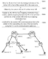
FIG. 6 is a flowchart of a method for data transmission based on the preceding system for data communications accordng to another embodiment of the present invention. The method in this embodiment is used to ensure the continuity of data transmission when either of the terminals moves within the area after a data transmission tunnel is established between the terminals. As shown inFIG. 6 , the method in this embodiment includes: - S600: Move by the terminal from the management area of the initial AR to that of the current AR in the same area.
- S602: Obtain by the current AR the LL of the initial AR.
- S604: Update by the AR the local mapping information base, namely, add the mapping between the ID of the terminal and the LL of the current AR to the local mapping information base; and
- S606: Establish by the current AR a communications link to the initial AR for transmitting the data of the terminal by using the LLs as the communications addresses.
- In practice, after the current AR establishes a data transmission tunnel to the initial AR, the subsequent data of the terminal (the data to be transmitted to or by the terminal) can be directly transmitted through the tunnel, without querying the information base.
- The following describes the method in this embodiment based on
FIG. 7 . - When terminal 10 in
area 1 and terminal 20 inarea 2 are communicating with each other, ifterminal 10 inarea 1 moves from the management area ofAR 11 inarea 1 to that ofAR 13 in the same area, the continuity of the call betweenterminal 10 and terminal 20 must be ensured. Therefore, the method includes: - receiving the LL of
AR 11 obtained byAR 13 of terminal 10 from the local mapping information base, where: in practice,AR 13 can obtain the LL ofAR 11 from the local mapping information base; in addition, because terminal moves within the same area, when attaching toAR 13, terminal 10 can carry information about the AR it previously attached to, namely, information about AR 11 (like ID); - buffering, by
AR 11, the data to be transmitted to terminal 10 afterterminal 10 leavesAR 11, where: in practice,AR 11 can set a buffering duration for the data ofterminal 10, and deregister the mapping between the ID of terminal 10 (ID1) and the LL ofAR 11 local mapping information base after the buffering duration expires; - updating, by
AR 13, the local mapping information base, namely, adding the mapping between ID1 ofterminal 10 and the LL ofAR 13 to the local mapping information base; and sending a link establishment request toAR 11 based on theLL ofAR 11; and - responding to, by
AR 11, the link establishment request fromAR 13 to establish the link (ifAR 11 does not buffer the data to be transmitted toterminal 10, no link needs to be established). - In practice, after the link is established, the communiation traffic between
terminal 10 and terminal 20 can be transmitted through the bi-directional link betweenAR 11 andAR 13. - Further, to optimize the route, after
AR 11 andAR 13 establish a link in between,AR 13 andABR 12 establish a communications link in between by using the LLs as the communications addresses, to replace the communications link between the fifth AR and the first AR for transmitting and receiving data for the terminal. After that, the subsequent data received byterminal 10 can be directly transmitted toAR 13 throughABR 12 instead ofAR 11. -
FIG. 8 is a flowchart of a method for data transmission based on the preceding system for data communications according to another embodiment of the present invention. The method in this embodiment is used to ensure the continuity of data transmission when either of the terminals moves to a different area after a data transmission tunnel is established between the terminals. As shown inFIG. 8 , the method in this embodiment includes: - S800: Move by the terminal from the management area of the initial ABR to that of the current ABR.
- S802: Notify the ABR by the initial AR that the terminal moves out of the management area of the initial ABR after the initial AR detects that the terminal moves out.
- S804: Notify the current AR by the current AR that the terminal moves to the management area of the current ABR after the current AR detects that the terminal moves in; and update the local mapping information base, namely, add the mapping between the ID of the terminal and the LL of the current AR to the local mapping information base.
- S806: Update by the current ABR the global mapping information base, namely, add the mapping between the ID of the terminal and the GL of the current ABR to the global mapping information base; obtain the GL of the initial ABR from the global mapping information base that is not updated.
- S808: Establish by the current ABR a communications link to the initial ABR for transmitting the data of the terminal by using the GLs as the communications addresses.
- In practice, after the current ABR establishes a data transmission link to the initial ABR, the subsequent data of the terminal (the data to be transmitted to or by the terminal) can be directly transmitted through the tunnel, without querying the information base.
- The following describes the method in this embodiment based on
FIG. 9 . - When terminal 10 in
area 1 and terminal 20 inarea 2 are communicating with each other, ifterminal 10 moves from the management area ofABR 12 inarea 1 to that ofABR 21 inarea 2, the continuity of the call betweenterminal 10 and terminal 20 must be ensured. Therefore, the method includes: - notifying, by
AR 11, theABR 12 thatterminal 10 leavesarea 1, afterterminal 10 leavesarea 1; buffering, byABR 12, the data to be transmitted from terminal 20 toterminal 10, where: in practice,AR 11 can set a buffering duration for the data ofterminal 10, and deregister the mapping between the ID of terminal 10 (ID1) and the LL ofAR 11 after the buffering duration expires; deregistering, byABR 12, the mapping between ID1 ofterminal 10 and the GL ofABR 12 in the global mapping information base; - notifying, by
AR 22,ABR 21 thatterminal 10 entersarea 2, when terminal 10 entersarea 2 and attaches toAR 22; and updating, byAR 22, the local mapping information base, namely, adding the mapping between ID1 ofterminal 10 and theLL ofAR 22 to the local mapping information base; - updating, by
ABR 21, the global mapping information, namely, adding the mapping between ID1 ofterminal 10 and the GL ofABR 21 to the global mapping information base, after receiving the notification fromAR 22; obtaining the GL ofABR 12 from the global mapping information base that is not updated; - sending, by
ABR 12, a link establishment request toABR 12; and - responding to, by
ABR 12, the link establishment request fromABR 21 to establish the link (ifAR 11 does not buffer the data to be transmitted toterminal 10, no link needs to be established). - In practice, after the link is established, the communications traffic between
terminal 10 and terminal 20 can be transmitted through the bi-directional link betweenABR 12 andABR 21. - Further, to optimize the route, after
ABR 12 responds to the link establishment request fromABR 21 to establish the link,ABR 12 notifiesABR 21 of the current ID of terminal 10 (the mapping betweenID 1 and the GL of ABR 21); and then,ABR 21 directly transmits the data from terminal 20 toterminal 10. - The embodiments of the present invention completely separate the ID, LL, and GL of the terminal, and thus solve the problems with the routing table expansion and scalability faced by the Internet. In this way, the terminal data can be transmitted without changing the terminal or the routing protocol stack. In addition, the hierarchical mapping helps reduces the amount of locally and globally stored information, and thus accelerating the query.
- Those skilled in the art can understand that computer programs can instruct the related hardware to complete all or part of the processes in the methods in the preceding embodiments. These programs can be stored in the readable storage medium of a computer. During execution, the program can include the processes in the embodiments of the preceding methods. The storage medium can be a disk, an optical disk, a read-only memory (ROM), or a random access memory (RAM).
Claims (20)
- A system for data communications, adapted to transmit data of a terminal that takes an identifier (ID) as source and destination addresses, wherein the system comprises at least one access router (AR) and at least one area border router (ABR):the AR is adapted to: set local locators (LLs), establish communications links to devices within an area by using the set LLs, and transmit received data through transmission routes, the transmission routes being obtained by querying mapping between the ID and the LLs in a local mapping information base according to a destination ID of the received data; andthe ABR is adapted to: set global locators (GLs) and the LLs, establish communications links to devices outside the area by using the set GLs, establish the communications links to the devices within the area by using the set LLs, and transmit the received data through the transmission routes, the tramission routes being obtained by querying the mapping between the ID and the GLs in a global mapping information base according to the destination ID of the received data.
- The system for data communications according to claim 1, wherein the AR comprises:a configuration module, adapted to set an local locator (LL) as an intra-area communications address of the AR;a link establishment module, adapted to establish the communications links to the devices within the area by using the set LL;a receiving module, adapted to receive the data;a query module, adapted to query whether the LL that maps the destination ID of the data exists in the local mapping information base by using the destination ID of the data received by the receiving module;a route identifying module, adapted to identify a route for transmitting the received data based on results of querying the local mapping information base by the query module; anda transmission module, adapted to transmit the received data through the transmission route identified by the route identifying module and the link established by the link establishment module.
- The system for data communications according to claim 2, wherein the route identifying module comprises:a first route identifying module, adapted to determine to transmit the data to the AR that maps the LL obtained through query if the query module obtains the LL that maps the destination ID of the data in the local mapping information base; anda second route identifying module, adapted to determine to transmit the data to the ABR that is bound to the AR in a same area if the query module does not identify an LL that maps the destination ID of the data in the local mapping information base.
- The system for data communications according to claim 2 or 3, wherein the AR further comprises:an information updating module, adapted to update the local mapping information base and notify the ABR in the same area of update results when the terminal enters or leaves a management area of the AR.
- The system for data communications according to claim 1, wherein the ABR comprises:a configuration module, adapted to set the global locator (GL) as an inter-area communications address and the LL as the intra-area communications address;a link establishment module, adapted to: establish the communications links to the devices outside the area by using the set GL, and establish the communications links to the devices within the area by using the set LL;a receiving module, adapted to: receive the data;a query module, adapted to query whether the LL that maps the destionation ID of the data exists in the local mapping information base by using the destination ID of the data received by the receiving module, or query whether the GL that maps the destination ID of the data exists in the global mapping information base;a route identifying module, adapted to identify the route for transmitting the received data based on the results of querying the local or global mapping information base by the query module; anda transmission module, adapted to: transmit the received data through the transmission route identified by the route identifying module and the link established by the link establishment module.
- The system for data communications according to claim 5, wherein the route identifying module further comprises at least one of:a first route identifying module (3071) adapted to: determine to transmit the data to the AR that maps the LL obtained through query if the query module obtains the LL that maps the destination ID of the data in the local mapping information base; anda second route identifying module (3073) adapted to: determine to transmit the data to the ABR that is bound to the AR in a same area if the query module does not identify the LL that maps the destination ID of the data in the local mapping information base.
- The system for data communications according to claim 5 or 6, wherein the ABR further comprises:an information updating module, adapted to: update the global or local mapping information base when the terminal enters or leaves a management area of the ABR.
- The system for data communications according to claim 5 or 6, wherein the ABR further comprises at least one of:a local mapping information storage module, adapted to: store the local mapping information base; anda global mapping informaiton storage module, adapted to: store the global mapping information base.
- The system for data communications according to claim 1, further comprising at least one of:a local mapping information storage device, adapted to store the local mapping information base; anda global mapping information storage device, adapted to store the global mapping information base.
- An access router (AR), comprising:a configuration module, adapted to set a local locator (LL) as an intra-area communications address of the AR;a link establishment module, adapted to: establish communications links to devices within an area by using the set LL;a receiving module, adapted to receive the data;a query module, adapted to query whether the LL that maps a destination identifier (ID) of the data exists in the local mapping information base by using the destinatioin ID of the data received by the receiving module;a route identifying module, adapted to: identify a route for transmitting the received data based on results of querying the local mapping information base by the query module; anda transmission module, adapted to: transmit the received data through the transmission route identified by the route identifying module and the link established by the link establishment module.
- An area border router (ABR), comprising:a configuration module, adapted to: set a global locators (GL) as an inter-area communications address and a local locator (LL) as an intra-area communications address;a link establishment module, adapted to: establish communications links to devices outside an area by using the set GL, and establish communications links to devices within the area by using the set LL;a receiving module, adapted to receive the data;a query module, adapted to query whether the LL that maps a destionation identifier (ID) of the data exists in a local mapping information base by using the destination ID of the data received by the receiving module, or query whether the GL that maps the destination ID of the data exists in a global mapping information base;a route identifying module, adapted to: identify a route for transmitting the received data based on results of querying the local or global mapping information base by the query module; anda transmission module, adapted to: transmit the received data through the transmission route identified by the route identifying module and the link established by the link establishment module.
- A method for data transmission, comprising:receiving, by a first access router (AR), data;identifying a transmission route based on results of querying a local mapping information base according to a destination identifier (ID) of the data; andtransmitting data, wherein the local mapping information base stores mappings between IDs and local locators (LLs).
- The method for data transmission according to claim 12, comprising:receiving, by a first AR, data transmitted by a terminal that takes the IDs as source and destination addresses; orreceiving, by a first AR, data transmitted by a first area border router (ABR) in a same area; orreceiving, by a first AR, data transmitted by a second AR in a same area.
- The method for data transmission according to claim 13, wherein the identifying of the transmission route by AR 11 based on the results of querying the local mapping information base through the destination identifier (ID) of the data and receiving of the data comprises:checking whether an LL that maps the destination ID of the received data exsits in the the local mapping information base by AR 11 according to the destination ID of the received data; and, after obtaining the LL that maps the destination ID through the query, determining to transmit the data to a third AR that maps the LL; andtransmitting the data through communications links by using an LL of a first AR as the source address and an LL of the third AR as the destination address.
- The method for data transmission according to claim 13, wherein the identifying of the transmission route by AR 11 based on the results of querying the local mapping information base through the destination identifier (ID) of the data and receiving of the data comprises:checking whether an LL that maps the destination ID of the received data exists in the local mapping information base by AR 11 according to the destination ID of the received data; and, after failing to obtain the LL, transmitting the data to a second ABR that is bound to a first AR in a same area; andtransmitting the data through communications links by using the LL of a first AR as the source address and an LL of the second ABR as the destination address.
- The method for data transmission according to claim 15, wherein the transmitting of the data by AR 11 through the communications links by using the LL of a first AR as the source address and the LL of the second ABR as the destination address comprises:checking, by the second ABR, a global mapping information base according to the destination ID of the data; and, after obtaining a global locator (GL) that maps the destination ID through the query, determining to transmit the data to a third ABR that maps the GL;transmitting, by the second ABR, the data through the communications link by using a GL of the second ABR as the source address and a GL of the third ABR as the destination address;checking, by the third ABR, the local mapping information base according to the destination ID of the data; and when the LL that maps the destination ID is obtained through the query, determining to transmit the data to a fourth AR that maps the LL; andtransmitting, by the third ABR, the data through the communications link by using an LL of the third ABR as the source address and an LL of the fourth AR as the destination address.
- A method for terminal mobility management, comprising:when a terminal moves from a management area of an initial access router (AR) to a management area of a current AR in a same area, establishing a communications link for transmitting data of the terminal, wherein local locators (LLs) of the current and initial ARs serve as communications addresses.
- The method for terminal mobility management according to claim 17, wherein: before the establishing of the communications link for transmitting the data of the terminal, wherein the LLs of the current and initial ARs serve as communications addresses, the method further comprises:obtaining, by the current AR, the LL of the initial AR; andupdating, by the current AR, a local mapping information base, namely, adding mapping between an identifier (ID) of the terminal and the LL of the current AR to the local mapping information base.
- A method for terminal mobility management, comprising:when a terminal moves from a management area of an initial area border router (ABR) to a management area of a current ABR, establishing a communications link for transmitting data of the terminal, wherein the current and initial ABRs take gloabal locators (GLs) as communications addresses.
- The method for terminal mobility management according to claim 19, wherein: before the establishing of the communications link for transmitting data of the terminal, wherein the current and initial ABRs take the GLs as the communications addresses, the method further comprise:detecting that the initial AR, which the terminal moves out, notifies the initial ABR of that the terminal has moved out of the management area of the initial ABR;detecting that the current AR, which the terminal moves in, notifies the current ABR of that the terminal has moved to the management area of the current ABR;updating, by the current AR, a local mapping information base, namely, adding mapping between an identifier (ID) of the terminal and a local locator (LL) of the current AR to the local mapping information base; andupdating, by the current ABR, a global mapping information base, namely, adding mapping between the ID of the terminal and a global locator (GL) of the current ABR to the global mapping information base; obtaining the GL of the initial ABR from the global mapping information base that is not updated.
Applications Claiming Priority (2)
| Application Number | Priority Date | Filing Date | Title |
|---|---|---|---|
| CN2008102195403A CN101753424B (en) | 2008-11-28 | 2008-11-28 | Data communication system, router, data sending and mobility management method |
| PCT/CN2009/072475 WO2010060304A1 (en) | 2008-11-28 | 2009-06-26 | Data communication system, router, data transmission and mobility management method |
Publications (2)
| Publication Number | Publication Date |
|---|---|
| EP2288089A1 true EP2288089A1 (en) | 2011-02-23 |
| EP2288089A4 EP2288089A4 (en) | 2011-06-29 |
Family
ID=42225228
Family Applications (1)
| Application Number | Title | Priority Date | Filing Date |
|---|---|---|---|
| EP09828565A Withdrawn EP2288089A4 (en) | 2008-11-28 | 2009-06-26 | Data communication system, router, data transmission and mobility management method |
Country Status (4)
| Country | Link |
|---|---|
| US (1) | US8730964B2 (en) |
| EP (1) | EP2288089A4 (en) |
| CN (1) | CN101753424B (en) |
| WO (1) | WO2010060304A1 (en) |
Families Citing this family (8)
| Publication number | Priority date | Publication date | Assignee | Title |
|---|---|---|---|---|
| CN102014043B (en) * | 2009-09-08 | 2013-12-04 | 中兴通讯股份有限公司 | Address mapping system, data transmission method and address mapping maintenance method |
| CN102025589B (en) * | 2009-09-18 | 2015-04-01 | 中兴通讯股份有限公司 | Method and system for realizing virtual private network |
| CN102088390B (en) * | 2009-12-08 | 2014-12-10 | 中兴通讯股份有限公司 | Implementation method of user mobility |
| CN101883055B (en) * | 2010-07-19 | 2013-11-20 | 福建星网锐捷网络有限公司 | Capacity expansion realization method and device of routing forwarding table and switching device |
| CN102546372B (en) * | 2010-12-24 | 2016-01-20 | 中兴通讯股份有限公司 | A kind of method and system improving mapping routing table service efficiency |
| WO2012088849A1 (en) * | 2010-12-27 | 2012-07-05 | 中兴通讯股份有限公司 | Method and system for obtaining connection information |
| CN106470156B (en) * | 2015-08-19 | 2020-07-10 | 中兴通讯股份有限公司 | Method and device for forwarding message |
| WO2017176428A1 (en) * | 2016-04-05 | 2017-10-12 | Wellaware Holdings, Inc. | Monitoring and controlling industrial equipment |
Family Cites Families (8)
| Publication number | Priority date | Publication date | Assignee | Title |
|---|---|---|---|---|
| US7831733B2 (en) * | 2001-07-06 | 2010-11-09 | Avaya Holdings Limited | Policy-based forwarding in open shortest path first (OSPF) networks |
| US8019889B1 (en) * | 2002-05-31 | 2011-09-13 | Cisco Technology, Inc. | Method and apparatus for making end-host network address translation (NAT) global address and port ranges aware |
| JP4173401B2 (en) * | 2003-05-01 | 2008-10-29 | 株式会社エヌ・ティ・ティ・ドコモ | Router, address identification information management server |
| CN100403708C (en) * | 2003-10-23 | 2008-07-16 | 余鲲 | Method for dynamically selecting interconnection network provide merchant for user |
| JP4423118B2 (en) | 2004-06-08 | 2010-03-03 | 株式会社エヌ・ティ・ティ・ドコモ | Mobile communication system, access router, management apparatus, and mobile communication method |
| US7916692B2 (en) | 2005-03-25 | 2011-03-29 | Nec Corporation | Mobile communication system, edge router, and transfer control method, program and recording medium used therefor |
| EP1708425A1 (en) * | 2005-03-31 | 2006-10-04 | Matsushita Electric Industrial Co., Ltd. | Tunnelling of multicast data |
| CN100428719C (en) | 2006-01-23 | 2008-10-22 | 北京交通大学 | Internet access method based on identity and location separation |
-
2008
- 2008-11-28 CN CN2008102195403A patent/CN101753424B/en active Active
-
2009
- 2009-06-26 EP EP09828565A patent/EP2288089A4/en not_active Withdrawn
- 2009-06-26 WO PCT/CN2009/072475 patent/WO2010060304A1/en active Application Filing
-
2010
- 2010-12-30 US US12/982,551 patent/US8730964B2/en active Active
Non-Patent Citations (4)
| Title |
|---|
| DAMIEN SAUCEZ ET AL: "Interdomain traffic engineering in a locator/identifier separation context", INTERNET NETWORK MANAGEMENT WORKSHOP, 2008. INM 2008. IEEE, IEEE, PISCATAWAY, NJ, USA, 19 October 2008 (2008-10-19), pages 1-6, XP031354923, ISBN: 978-1-4244-2964-6 * |
| MIN-KYO IN ET AL: "Splitting mechanism for IP into Identifier and Locator in NGN", TOWARD NETWORK INNOVATION BEYOND EVOLUTION : THE 9TH INTERNATIONAL CONFERENCE ON ADVANCED COMMUNICATION TECHNOLOGY ; ICACT 2007 ; PHOENIX PARK, KOREA, FEB. 12 - 14, 2007 ; PROCEEDINGS, IEEE TECHNICAL ACTIVITIES, PISCATAWAY, NJ, USA, 1 February 2007 (2007-02-01), pages 1974-1977, XP031085134, ISBN: 978-89-5519-131-8 * |
| See also references of WO2010060304A1 * |
| VED P KAFLE ET AL: "Generic identifiers for ID/locator split internetworking", INNOVATIONS IN NGN: FUTURE NETWORK AND SERVICES, 2008. K-INGN 2008. FIRST ITU-T KALEIDOSCOPE ACADEMIC CONFERENCE, IEEE, PISCATAWAY, NJ, USA, 12 May 2008 (2008-05-12), pages 299-306, XP031272311, ISBN: 978-92-61-12441-0 * |
Also Published As
| Publication number | Publication date |
|---|---|
| EP2288089A4 (en) | 2011-06-29 |
| US20120002600A1 (en) | 2012-01-05 |
| CN101753424A (en) | 2010-06-23 |
| WO2010060304A1 (en) | 2010-06-03 |
| CN101753424B (en) | 2012-07-04 |
| US8730964B2 (en) | 2014-05-20 |
Similar Documents
| Publication | Publication Date | Title |
|---|---|---|
| EP2288089A1 (en) | Data communication system, router, data transmission and mobility management method | |
| US10027623B2 (en) | Internet protocol address resolution | |
| US9769072B2 (en) | Method and apparatus for scalable content routing and mobility in named data networks | |
| CN100583903C (en) | Arrangement for traversing an IPv4 network by IPv6 mobile routers | |
| EP1139632B1 (en) | Method for packet communication with mobile node | |
| JP4173401B2 (en) | Router, address identification information management server | |
| US9414218B2 (en) | Dynamic discovery of home agent with specific binding | |
| JP4595619B2 (en) | Mobile router, home agent, and terminal location management method | |
| CN102123182B (en) | Method for separating host identifier (HID) mark from locator based on IPV6 (Internet Protocol Version 6) address | |
| JP2008510440A (en) | Method for performing communication between a mobile IPv6 node and an IPv4 communication partner | |
| WO2013007130A1 (en) | Location/id separation protocol motion node, motion control method and motion node | |
| JP5905722B2 (en) | System and method for mobile IP | |
| US20130176943A1 (en) | System and Method for Distributed Mobility Management | |
| US20150023262A1 (en) | Device and method for realizing identity and locator separation network | |
| EP1874005A1 (en) | A personal network comprising a plurality of clusters | |
| EP2482585B1 (en) | Method and system for realizing terminal handover | |
| US20090147759A1 (en) | Method and apparatus for supporting mobility of node using layer 2/layer 3 addresses | |
| WO2013083037A1 (en) | Update packet processing method and system, mapping server and mobile node | |
| JP2006114946A (en) | Mobile network system | |
| KR101356721B1 (en) | Method for managing host location of router | |
| KR100714526B1 (en) | Method for transmitting packet from correspondent node to mobile node | |
| US20110185083A1 (en) | Identifier and locator structure, and communication method based on the structure | |
| CN103166856B (en) | A kind of dynamic movability management method based on LISP protocol and system | |
| KR101082583B1 (en) | System and Method for Managing Mobility of Mobile Node | |
| JP4595647B2 (en) | Translator |
Legal Events
| Date | Code | Title | Description |
|---|---|---|---|
| PUAI | Public reference made under article 153(3) epc to a published international application that has entered the european phase |
Free format text: ORIGINAL CODE: 0009012 |
|
| 17P | Request for examination filed |
Effective date: 20101227 |
|
| AK | Designated contracting states |
Kind code of ref document: A1 Designated state(s): AT BE BG CH CY CZ DE DK EE ES FI FR GB GR HR HU IE IS IT LI LT LU LV MC MK MT NL NO PL PT RO SE SI SK TR |
|
| AX | Request for extension of the european patent |
Extension state: AL BA RS |
|
| REG | Reference to a national code |
Ref country code: DE Ref legal event code: R079 Free format text: PREVIOUS MAIN CLASS: H04L0012560000 Ipc: H04W0008020000 |
|
| A4 | Supplementary search report drawn up and despatched |
Effective date: 20110530 |
|
| RIC1 | Information provided on ipc code assigned before grant |
Ipc: H04L 12/56 20060101ALI20110524BHEP Ipc: H04L 29/12 20060101ALI20110524BHEP Ipc: H04W 8/02 20090101AFI20110524BHEP |
|
| DAX | Request for extension of the european patent (deleted) | ||
| 17Q | First examination report despatched |
Effective date: 20121109 |
|
| STAA | Information on the status of an ep patent application or granted ep patent |
Free format text: STATUS: THE APPLICATION IS DEEMED TO BE WITHDRAWN |
|
| 18D | Application deemed to be withdrawn |
Effective date: 20130522 |