EP2287964A1 - Device for filtering radio frequency signals and system thereof - Google Patents
Device for filtering radio frequency signals and system thereof Download PDFInfo
- Publication number
- EP2287964A1 EP2287964A1 EP09305769A EP09305769A EP2287964A1 EP 2287964 A1 EP2287964 A1 EP 2287964A1 EP 09305769 A EP09305769 A EP 09305769A EP 09305769 A EP09305769 A EP 09305769A EP 2287964 A1 EP2287964 A1 EP 2287964A1
- Authority
- EP
- European Patent Office
- Prior art keywords
- cap
- seg2
- capacitive means
- segment
- resonances
- Prior art date
- Legal status (The legal status is an assumption and is not a legal conclusion. Google has not performed a legal analysis and makes no representation as to the accuracy of the status listed.)
- Withdrawn
Links
Images


Classifications
-
- H—ELECTRICITY
- H01—ELECTRIC ELEMENTS
- H01P—WAVEGUIDES; RESONATORS, LINES, OR OTHER DEVICES OF THE WAVEGUIDE TYPE
- H01P1/00—Auxiliary devices
- H01P1/20—Frequency-selective devices, e.g. filters
- H01P1/201—Filters for transverse electromagnetic waves
- H01P1/202—Coaxial filters
Definitions
- the invention relates to a device for filtering radio frequency signals according to the preamble of claim 1 and to a system comprising the device,
- RF filters radio frequency
- RF radio frequency
- the central inner conductor comprises short sections of high-impedance lines, which simulate series inductances, alternating with short sections of very-low impedance lines, which simulate shunt capacitances.
- the short sections of high-impedance lines which are depicted as inductive means in the following, are usually thin rods or thin wires and are surrounded usually by air as a dielectric,
- the short sections of very-low impedance lines which are depicted as capacitive means in the following due to their capacitive properties, are usually solid disks with a small rim of the dielectric between the solid disks and the cylindrical outer conductor.
- the operating frequency range is adopted to the lower GSM frequency ranges such as GSM 400, GSM 700, GSM 850 or GSM 900 and if a same filter assembly is used as for UMTS, size and length of the coaxial low-pass filter has to be increased, because of the dependency between a length of the inductive means and a frequency range of the radio frequency signal,
- an impedance of the capacitive means By increasing a diameter of the capacitive means an impedance of the capacitive means can be decreased and by decreasing a diameter of the inductive means an impedance of the inductive means can be increased. Thereby, a larger difference in the impedances of the capacitive means and the inductive means can be achieved and a length of the capacitive means and of the inductive means can be reduced.
- fr n • C / (2 • L) with fr being a resonator frequency, n being a natural number, c being the speed of light, and L being a length of the resonator.
- the higher order modes within the operating frequency range must be suppressed to avoid a degradation of a spectral characteristic of a radio frequency signal filtered by the coaxial low-pass filter.
- One possibility to suppress the higher order modes in the coaxial low-pass filter is to arrange radio frequency absorbers around the inductive means.
- the way of suppressing resonances of higher order modes affects an assembly of a coaxial low-pass filter and the spectral characteristic of a radio frequency signal filtered by the coaxial low-pass filter.
- a device comprising means for filtering radio frequency signals and means for suppressing resonances, wherein the means for filtering comprise at least one capacitive means, and wherein the at least one capacitive means is adapted for providing the means for suppressing the resonances.
- the device provides a first advantage of not requiring any additional components such as the radio frequency absorbers within a housing of the device for the suppressing of the resonances of higher order modes, which otherwise would have been generated in the device or which are generated elsewhere and would traverse the device.
- the device is for example a coaxial low-pass filter
- additional advantages are related to a size reduction of the coaxial low-pass filter up to 50 percent in comparison to a size, if a length of the device is not reduced.
- the smaller size results in lower manufacturing costs of the low-pass filter itself and in a smaller installation space required by the low-pass filter, if the low-pass filter is implemented in a system such as a tower mounted amplifier or a tower mounted booster. Therewith, also manufacturing costs of the system can be reduced.
- the at least one capacitive means is adapted at a border area of said at least one capacitive means. This provides the benefit, that only the higher-order modes, which am plitude distributions have a larger cross sectional area than an amplitude distribution of a fundamental mode are affected by the of least one capacitive means.
- the at least one capacitive means is adapted by adapting a form of the of least one capacitive means. This provides the advantage of reducing a reflectivity of the at least one capacitive means for the higher-order modes of the radio frequency signals in such a way, that a resonator cavity for the higher-order modes is avoided and the resonances will not be generated or will only be generated with very low amplitude levels.
- the form of the at least one capacitive means comprises a solid body with at least one opening or with at least one notch. This offers the benefit of positioning the opening or the notch at the capacitive means at a location, where the resonances of the higher order modes are affected but the fundamental mode of the radio frequency signal is not affected.
- the at least one opening or the at least one notch is used to reduce the reflectivity at some locations of the at least one capacitive means and thereby let a signal of the higher-order modes pass through and prevent a trapping and a resonating of the higher-order modes.
- a further benefit is a reduction of material to be required for the capacitive means, which results in reduced material costs.
- the at least one notch is arranged in a radial direction. This provides a benefit of a simple and accurate manufacturing of the at least one capacitive means with the least one notch for example by milling and by simply rotating the at least one capacitive means, if further notches may be used.
- a number and a size of the at least one opening or the at least one notch is adapted to a predefined capacitance of said at least one capacitive meons. This offers the advantage of balancing the number and the size of the of least one opening or the at least one notch between a maximizing of the suppressing of the resonances and a minimizing of an effect of the openings or notches on a required capacitive property of the at least one capacitive means.
- a cross section of the at least one capacitive means comprises a first segment and at least one second segment, and a radial distance or an average radial distance of a border of the first segment is larger than a radial distance or an average radial distance of a border of the at least one second segment.
- the least one capacitive means is adapted by adapting a composition of the at least one capacitive means. This provides the benefit of not requiring to change or adopt the form of the at least one capacitive means.
- a cross section of the form of the at least one capacitive means comprises a first segment and at least one second segment, and the first segment comprises at least one conductive material and the at least one second segment comprises at least one dielectric material.
- the at least one opening or the at least one notch is filled with the at least one dielectric material and thereby combining the advantages, of corresponding embodiments described above.
- Systems such as jumper and feeder cable connections between a base station cabinet ond antennas of a base station, duplex filters for base stations, tower mounted amplifiers, tower mounted boosters, or other coaxial cable connections may comprise devices according to the embodiments of the invention.
- FIG. 1 shows schematically a seven pole coaxial fitter CF according to the prior art.
- the coaxial filter CF comprises a cylindrical outer conductor CYL_OC1 and a central inner conductor CEN_IC1.
- the central inner conductor CEN _ IC1 is located in an axial position of the cylindrical outer conductor CYL_OC1 and is an assembly of several components.
- the central inner conductor CEN_IC1 comprises two cylindrical inner conductors CYL-IC1 CYL_IC2 at both ends of the central inner conductor CEN_IC1.
- the central inner conductor CEN_IC1 further comprises in a middle part four solid disks CAP_M1, CAP_M2, CAP_M3, CAP_M4, which are short sections of very-low impedance lines and which are depicted as capacitive means in the following due to their capacitive properties.
- the capacitive means CAP_M1, CAP_M2,CAP_M3, CAP_M4 are surrounded usually with a small rim of a dielectric such as air.
- the central inner conductor CEN_IC1 further comprises in the middle part three solid cylinders IND_M1, IND_M2, IND_M3, which are short sections of high-impedance lines and which are depicted as inductive means in the following due to their inductive properties.
- the inductive means IND_M1, IND_M2, IND_M3 are usually thin rods or thin wires and are surrounded also by the dielectric.
- the capacitive means CAP_M1, CAP_M2, CAP_M3, CAP_M4 and the inductive means IND_M1, IND_M2, IND_M3 add up to seven poles of the seven pole coaxial filter CF and are arranged in an alternating composition CAP_M1 - IND_M1 - CAP_M2 - IND_M2 - CAP_M3 - IND_M3 - CAP_M4 with electrical contact between two adjacent components in each case.
- a first one CAP_M1 of outer capacitive means CAP_M1, CAP_M4 is in electrical contact to a first one CYL_IC1 of the two cylindrical inner conductors CYL_IC1, CYL_IC2 and a second one CAP_M4 of the outer capacitive means CAP_M1, CAP_M4 is in electrical contact to a second one CYL_IC2 of the two cylindrical inner conductors CYL_IC1, CYL_IC2,
- the inner capacitive means CAP_M2, CAP_M3 are used for a first operation frequency range.
- the outer capacitive means CAP_M1, CAP_M4, which may be thicker than the inner capacitive means CAP_M2, CAP_M3, can be used for a second operation frequency range.
- a radio frequency signal passing the coaxial filter CFfrom on input to an output is modified by spectral characteristics of the coaxial filter CF, which are determined by an arrangement and geometrical form of the components of the middle part of the central inner conductor CEN_IC1.
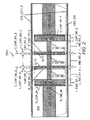
- Figure 2 shows schematically a longitudinal section of a device DEV according to a first embodiment of the invention.
- the detailed structure of the device DEV is not critical, and os can be understood by those skilled in the art, that the detailed structure of the device DEV may vary without departing from the scope of the invention,
- the device DEV may be for example coaxial fitter, which comprises a cylindrical outer conductor CYL_OC2 and a central inner conductor CEN_IC2.
- the device DEV may be used as a low-pass filter, a high-pass filter, or a band pass filter.
- a space between the central inner conductor CEN_IC2 and the cylindrical outer conductor CYL_OC2 may be filled with air AIR as a dielectric.
- the space many be filled with another gaseous dielectric material, with a solid dielectric material, or may be evacuated to have a vacuum between the central inner conductor CEN_IC2 and the cylindrical outer conductor CYL_OC2.
- the cylindrical outer conductor CYL_OC2 preferably comprises between both ends of the coaxial filter a conductive hollow cylinder as a single component.
- the outer conductor may comprise tapered sections at the both ends of the device DEV, which permits an enlarging of a coaxial region at the centre of the device DEV and which may reduce dissipation losses.
- the central inner conductor CEN_IC2 is located in an axial position of the cylindrical outer conductor CYL_OC2 and is an assembly of several components.
- the central inner condudor CEN_IC2 may be a single component with different longitudinal sections.
- Two cylindrical inner conductors CYL_IC1_2, CYL_IC2_2 of the central inner conductor CEN_IC2 are located at both ends of the central inner conductor CEN_IC2.
- the two cylindrical inner conductors CYL_IC1_2, CYL_IC2_2 may comprise tapered sections at both ends of the central inner conductor CEN_IC2, which permits an enlarging of a coaxial region at the centre of the device DEV and which may reduce dissipation losses.
- a middle part of the central inner conductor CEN_IC2 comprises two solid disks as two outer capacitive means CAP_M1_2, CAP_M4_2, two further solid disks as inner capacitive means CAP_M2_2, CAP_M3_2, and three solid cylinders as inductive means IND_M1_2, IND_M2_2, IND_M3_2 in an alternating composition CAP_M1_2 - IND_M1_2 - CAP_M2_2 - IND_M2_2 - CAP_M3_2 - IND_M3_2 - CAP_M4_2.
- the device DEV shown in Figure 2 is a seven pole low-pass filter with four capacitive means (four poles) and three inductive means (further three poles),
- the central inner conductor CEN_IC2 may comprise more than seven poles with more than four capacitive means and/or more than three inductive means,
- the central inner conductor CEN_IC2 may comprise less than seven poles with the at least one capacitive means and less than three further capacitive means and at least one inductive means and less than two further inductive means.
- a filter may be used which comprises in the central part two inductive means and one capacitive means in-between (three pole low-pass filter) or two capacitive means and one inductive means in-between (further three pole low-pass filter).
- the inner capacitive means GAP_M2_2, CAP_M3_2 instead of the inner capacitive means GAP_M2_2, CAP_M3_2 being circular disks, the inner capacitive means CAP_M2_2, CAP_M3_2 may comprise another geometrical form such as elliptical disks.
- the inner capacitive means CAP_M2_2, CAP_M3_2 may be used for a first operation frequency range.
- the outer capacitive means CAP_M1_2, CAP_M4_2, which may be thicker than the inner capacitive means CAP_M2_2, CAP_M3_2, may be used for a second operation frequency range.
- the outer capacitive means CAP_M1_2, CAP_M4_2 may be not required, if a second operation frequency range is not required.
- a geometrical form of the inner capacitive means CAP_M2_2, CAP_M3_2 is adopted for providing means for suppressing the resonances according to a first group of embodiments of the invention. Therefore according to Figure 2 , a first one C_CAP_M2_2 of the inner capacitive means CAP_M2_2, CAP_M3_2 may comprise at least one slit SLT1 and a second one C_CAP_M3_2 of the inner capacitive means CAP_M2_2, CAP_M3_2 may comprise at least one further slit SLT4. This is described in more detail according to Figure 3 with the aid of cross sections C_CAP_M2_2, C_GAP_M3_2 of the inner capacitive means CAP_M2_2, CAP_M3_2.
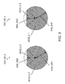
- FIG. 3 cross sections of the inner capacitive means CAP_M2_2, GAP_M3_2 are shown according to the first embodiment of the invention.
- a solid body of the first one CAP_M2_2 of the inner capacitive means CAP_M2_2, GAP_M3_2 comprises three slits SLT1, SLT2, SLT3 in a radial direction of the first one CAP_M2_2 of the inner capacitive means CAP_M2_2, CAP_M3_2 and a solid body of the second one CAP_M3_2 of the inner capacitive means CAP_M2_2, CAP_M3_2 comprises three further slits SLT4, SLT5, SLT6 in a radial direction of the second one CAP_M3_2 of the inner capacitive means GAP_M2_2, CAP_M3_2.
- first one and the second one of the inner capacitive means CAP_M2_2, CAP_M3_2 comprise at least one slit but less or more than three slits.
- slits with rectangular geometrical form instead of slits with rectangular geometrical form, notches having geometrical forms such as quadratic or wedge form or notches with arbitrary geometrical form may be used.
- a number of slits or notches may be adapted to a predefined capacitance of the inner capacitive means CAP_M2_2, CAP_M3_2 in such a way, that a suppressing of the resonances is maximized and a degrading effect of the slits or notches on a required capacitive property of the inner capacitive means CAP_M2_2, CAP_M3_2 is minimized.
- Each slit SLT1, SLT2, SLT3, SLT4, SLT5, and SLT6 has a size given by a width W_SLT and a depth D_SLT, which may be adopted to the predefined capacitance of the inner capacitive means CAP_M2_2, CAP_M3_2 in such a way, that the suppressing of the resonances is maximized and a degrading effect of the size of the slits or notches on a required capacitive property of the inner capacitive means CAP_M2_2, CAP_M3_2 is minimized.
- at least two slits have different sizes or all the slits SLT1, SLT2, SLT3, SLT4, SLT5, and SLT6 have different sizes.
- CAP_M3_2 a form of the inner capacitive means CAP_M2_2, CAP_M3_2 is adopted to reduce a reflectivity of the inner capacitive means CAP_M2_2, CAP_M3_2 for the higher-order modes to suppress any resonances of the higher-order modes. Thereby, an effect of a cavity resonator for the resonances can be reduced or even avoided by means of the adapted inner capacitive means CAP_M2_2, CAP_M3_2.
- a lateral extension of a fundamental mode of the radio frequency signal is confined to a central axis of the device DEV and a central region of the inner capacitive means CAP_M2_2, CAP_M3_2.
- a reflectivity of the fundamental mode is not affected by the slits SLT1, SLT2, SLT3, SLT4, SLT5, SLT6, which extensions are preferably limited to a border area of the inner capacitive means CAP_M2_2, CAP_M3_2.
- a solid body of a first one CAP_M2_3 of the inner capacitive means CAP_M2_3, CAP_M3_3 comprises three circular openings OP1, OP2, OP3 in an outer part of the first one CAP_M2_3 of the inner capacitive means CAP_M2_3, CAP_M3_3 and a solid body of a second one CAP_M3_3 of the inner capacitive means CAP_M2_3, CAP_M3_3 comprises three further circular openings OP4, OP5, OP6 in an outer part of the second one CAP_M3_3 of the inner capacitive means CAP_M2_3, CAP_M3_3.
- first one and the second one of the inner capacitive means CAP_M2_3, CAP_M3_3 comprise at least one circular opening but less or more than three circular openings.
- openings with geometrical form such as an ellipse, a square, or a rectangle or openings with arbitrary geometrical form may be used.
- a number of the openings may be adapted to a predefined capacitance of the inner capacitive means CAP_M2_3, CAP_M3_3 in such a way, that a suppressing of the resonances is maximized and a degrading effect of the openings on a required capacitive property of the inner capacitive, means CAP_M2_3, CAP_M3_3 is minimized.
- Each opening OP1, OP2, OP3, OP4, OP5, OP6 has a size given by a width W_OP, which may be adapted to the predefined capacitance of the inner capacitive means CAP_M2_3, CAP_M3_3 in such a way, that the suppressing of the resonances is maximized and a degrading effect of the size of the openings on a required capacitive property of the inner capacitive means CAP_M2_3, CAP_M3_3 is minimized.
- at least two openings have different sizes or all the openings OP1, OP2, OP3, OP4, OP5, and OP6 have different sizes.
- CAP_M3_3 o form of the inner capacitive means CAP_M2_3, CAP_M3_3 is adapted to reduce the reflectivity of the inner capacitive means CAP_M3_3, CAP_M3_3 for the higher-order modes of the radio frequency signals and thereby suppressing the resonances of the higher-order modes.
- An effect of a cavity resonator for the higher-order modes can be reduced or even avoided by means of the adapted inner capacitive means CAP_M2_3, CAP_M3_3.
- a reflectivity of the fundamental mode is not affected by the openings OP1, OP2, OP3, OP4, OP5, OP6, which extensions are preferably limited to a border area of the inner capacitive means CAP_M2_3, CAP_M3_3.
- a solid body of a first one CAP_M2_4 of inner capacitive means CAP_M2_4, CAP_M3_4 comprises a first segment SEG2_4_1 and a second segment SEG2_4_2.
- a border of the second segment SEG2_4_2 has a second radial distance RAD_DIS2 respectively a second average radial distance which is smaller than a first radial distance RAD_DIS1 respectively a first average radial distance of a border of the first segment SEG2_4_1.
- the border of the second segment SEG2_4_2 may be a straight border, In further alternatives, the border may be for example meandering or forked.
- the solid body of the first one CAP_M2_4 of the inner capacitive means CAP_M2_4, CAF_M3_4 may comprise further second segments having a border with a second radial distance or a second average radial distance smaller than the first segment of the solid body of the first one CAP_M2_4 of the inner capacitive means CAP_M2_4, CAP_M3_4.
- a solid body of a second one CAP_M3_4 of the inner capacitive means CAP_M2_4, CAP_M3_4 comprises a first segment SEG3_4_1 end a second segment SEG3_4_2.
- a border of the second segment SEG3_4_2 has the second radial distance RAD_DIS2 respectively the second average radial distance which is smaller than the first radial distance RAD_DIS1 respectively the first average distance of a border of the first segment SEG3_4_1.
- a number of second segments with a border having a smaller radial distance or smaller average radial distance than the radial distance of the border of the first segment may be adopted to a predefined capacitance of the inner capacitive means CAP_M2_4, CAP_M3_4 in such a way, that a suppressing of the resonances is maximized and a degrading effect of the openings on a required capacitive property of the inner capacitive means CAP_M2_4, CAP_M3_4 is minimized.
- a size of the radial distance or the overage radial distance of the border of the second segments SEG2_4_2, SEG3_4_2 may be adapted to the predefined capacitance of the inner capacitive means CAP_M2_4, CAP_M3_4 in such a way, that the suppressing of the resonances is maximized and a degrading effect of the size of the openings on a required capacitive, property of the inner capacitive means CAP_M2_4, CAP_M3_4 is minimized.
- CAP_M3_4 a form of the inner capacitive means CAP_M2_4, CAP_M3_4 is adapted to reduce the reflectivity of the inner capacitive means CAP_M2_4, CAP_M3_4 for the higher-order modes to suppress the resonances. Thereby, the effect of the cavity resonator for the resonances can be reduced or even avoided by means of the adapted inner capacitive means CAP_M2_4, CAP_M3_4.
- the reflectivity of the fundamental mode is not affected by the second segments SEG2_4_2, SEG3_4_2, which extensions are preferab!y limited to a border area of the inner capacitive means CAP_M2_4, CAP_M3_4.
- FIG. 6 further cross sections of capacitive means according to a second group of embodiments of the invention are shown. Cross sections of solid bodies of second ones of the inner capacitive means are not shown for simplification.
- the at least one capacitive means is adapted by adapting a composition of the at least one capacitive means.
- a solid body of an inner capacitive means CAP_M2_5 comprises four segments SEG2_5_1, SEG2_5_2, SEG2_5_3, SEG2_5_4.
- a first segment SEG2_5_1 may be identical to the solid body of the first one CAP_M2_2 of the inner capacitive means CAPM2_2, CAP_M3_2 according to Figure 3 .
- SEG2_5_2, SEG2_5_3, SEG2_5_4 may be identical to a location and expansion of the three slits SLT1, SLT2, SLT3 of the solid body of the first one CAP_M2_2 of the inner capacitive means CAPM2_2, CAP_M3_2 according to Figure 3 .
- the first segment SEG2_5_1 may comprise a conductive material as being used for the central inner conductor of the coaxial filter.
- the further three segments SEG2_5_2, SEG2_5_3, SEG2_5_4 may comprise a dielectric material, which is not conductive. In that case, the three slits SLT1, SLT2, SLT3 may be filled with the dielectric material.
- the further three segments SEG2_5_2, SEG2_5_3, SEG2_5_4 may comprise different dielectric materials.
- less than three segments but at least one segment or more than the further three segments SEG2_5_2, SEG2_5_3, SEG2_5_4 may comprise a dielectric material.
- the further three segments SEG2_5_3, SEG2_5_3, SEG2_5_4 may be arbitrary located at the inner capacitive means CAP_M2_5.
- a composition of the inner capacitive means CAP_M2_5 is adapted to reduce the reflectivity of the inner capacitive means CAP_M2_5 for the higher-order modes to suppress the resonances of the higher-order modes.
- the effect of the cavity resonator for the resonances can be reduced or even avoided by means of the adapted inner capacitive means CAP_M2_5.
- a reflectivity of the fundamental mode is not affected by the further three segments SEG2_5_2, SEG2_5_3, SEG2_5_4, which extensions are preferably limited to o border area of the inner capacitive means CAP_M2_5.
- a solid body of an inner capacitive means CAP_M2_6 comprises four sesments SEG2_6_1, SEG2_6_2, SEG2_6_3, SEG2_6_4.
- a first segment SEG2_6_1 may be identical to the solid body of the first one CAP_M2_3 of the inner capacitive means CAPM2_3, CAP_M3_3 according to Figure 4 .
- SEG2_6_2, SEG2_6_3, SEG2_6_4 may be identical to a location and expansion of the three openings OP1, OP2, OP3 of the solid body of the first one CAP_M2_3 of the inner capacitive means CAPM2_3, CAP_M3_3 according to Figure 4 .
- the first segment SEG2_6_1 comprises a conductive material as being used for the central inner conductor of the coaxial filter.
- the further three segments SEG2_6_2, SEG2_6_3, SEG2_6_4 comprise a dielectric material, which is not conductive. In that case, the three openings OP1, OP2, OP3 may be filled with the dielectric material.
- the further three segments SEG2_6_2, SEG2_6_3; SEG2_6_4 may comprise different dielectric materials.
- less than three segments but at least one segment or more than the further three segments SEG2_6_ 2, SEG2_6_3, SEG2_6_4 comprise a dielectric material.
- the further three segments SEG2_6_2, SEG2_6_3, SEG2_6_4 may be arbitrary located at the inner capacitive means CAP_M2_6.
- a composition of the inner capacitive means CAP_M2_6 is adapted to reduce the reflectivity of the inner capacitive means CAP_M2_6 for the higher-order modes to suppress the resonances of the higher-order modes.
- the effect of the cavity resonator for the resonances can be reduced or even avoided by means of the adapted inner capacitive means CAP_M2_6.
- a reflectivity of the fundamental mode is not affected by the further three segments SEG2_6_2, SEG2_6_3, SEG2_6_4, which extensions are preferably limited to a border area of the inner capacitive means CAP_M2_6.
- a solid body of an inner capacitive means CAP_M2_7 comprises two segments SEG2_7_1, SEG2_7_2.
- a first segment SEG2_7_1 may be identical to the solid body of the first one CAP_M2_4 of the inner capacitive means CAPM2_4, CAP_M3_4 according to Figure 5 .
- a second segment SEG2_7_2 may be used to add up to a circular cross section of the solid body of the inner capacitive means CAP_M2_7.
- the first segment SEG2_7_1 may comprise a conductive material as being used for the central inner conductor of the coaxial filter,
- the second segment SEG2_7_2 may comprise a dielectric material, which is not conductive.
- the inner capacitive means CAP_M2_7 may comprise further second segments with a same dielectric material of with different dielectric materials.
- At least two second segments are uniform or arbitrary located at the inner capacitive means CAP_M2_7.
- a composition of the inner capacitive means CAP_M2_7 is adopted to reduce the reflectivity of the inner capacitive means CAP_M2_7 for the higher-order modes to suppress the resonances of the higher-order modes.
- the effect of the cavity resonator for the resonances can be reduced or even avoided by means of the adapted inner capacitive means CAP_M2_7.
- a reflectivity of the fundamental mode is not affected by the second segment SEG2_7_2, which extension is preferably limited to a border area of the inner capacitive means CAP_M2_7.
- the invention is not limited to an application of a single embodiment in the device DEV but also can be used for a combination of several of the embodiments in the device DEV such as a capacitive means comprising at least one opening and at least one notch or two capacitive means, wherein a first one comprises at least one opening and a second one comprises at least one notch.
- the device DEV may be for example a printed-circuit, strip-line filter and the embodiment according to Figure 5 of the coaxial filter can be simply adopted by reducing a lateral dimension of the capacitive means of the printed-cifcuit, strip-line filter on one side.
- the device DEV may be for example a corrugated waveguide filter and the embodiment according to Figure 6 b) of the coaxial filter can be simply adopted by introduction of dielectric layers within the waveguide structure by etching and deposition processes as being used in semiconductor device fabrication.
- a tower mounted bopster TMB may be located between a base station and an antenna system,
- the tower mounted booster TMB is preferably located at a top of an antenna most next to the antenna system.
- BTS base transceiver station
- the tower mounted booster TMB may be connected to the antenna system via an antenna connection C-ANT1 and may be connected to a base station cabinet via a base station connection G-BTS1.
- the tower mounted booster TMB may comprise a duplexer DUP, a coupler COUP, a power amplifier PA, and a low noise amplifier LNA1,
- a received signal coming from the antenna system is delivered to a receiving path of the tower mounted booster TMB via a junction J1, is filtered by a receive filter RX of the duplexer DUP and amplified by the low-noise amplifier LNA1 and is coupled to the base station connection C-BTS1 via the coupler COUP.
- a transmit signal coming from the base station cabinet is coupled to a transmit path of the tower mounted booster TMB via the coupler COUP, is amplified by the power amplifier PA, is filtered by the device DEV being for example a coaxial low-pas, filter, is further filtered by a transmit filter TX1 and is delivered to the antenna connection C-ANT1 via the junction J1.
- the device DEV may be located for example at an end of the antenna connection C-ANT1 next to the antenna system or between a feeder cable and a jumper cable of the base station connection C-BTS1.
- a tower mounted amplifier TMA may be located between a base station and an antenna system.
- the tower mounted amplifier TMA is preferably located at a top of an antenna mast next to the antenna system.
- the tower mounted amplifier TMA is preferably used for reducing a base station noise figure and thereby can improve an overall receiver sensitivity to be able to receive weaker radio frequency signals.
- the tower mounted amplifier TMA may be connected to the antenna system via an antenna connection C-ANT2 and may be connected to a base station cabinet via a base station connection C-BTS2.
- the tower mounted amplifier TMA may comprise a first receive filter RX_F, a low noise amplifier LNA2, and a second receive filter RX_B in a receive path and the device DEV being for example a coaxial low-pass filter and a transmit filter TX2 in a transmit path.
- the receive path and the transmit path are splitted and combined by two junctions J2, J3.
- the device DEV may be located for example at an end of the antenna connection C-ANT2 next to the antenna system or between a feeder cable and a jumper cable of the base station connection C-BTS2.
- the device DEV may be used in duplex filters for base stations, in receive paths of radio communication systems or in transmission systems for radio frequency signals at a junction between two cables of the transmission systems.
- the invention allows for a smaller required space for the device DEV within the housings of the duplexer DUP, the tower mounted booster TMB, or the tower mounted amplifier TMA and thereby may reduce manufacturing costs.
- the invention is not limited to an application of a single embodiment in systems such as the tower mounted booster TMB or the tower mounted amplifier TMA but also can be used by combining of several of the embodiments of the invention in such systems.
Abstract
The invention relates to a device (DEV) comprising means for filtering radio frequency signals and means for suppressing resonances, wherein the means for filtering comprise at least one capacitive means (CAP_M2_2, CAP_M3_2), and wherein the at least one capacitive means (CAP_M2_2, CAP_M3_2) is adapted for providing the means for suppressing the resonances. The invention further relates to a system comprising the device.
Description
- The invention relates to a device for filtering radio frequency signals according to the preamble of
claim 1 and to a system comprising the device, - RF filters (RF = radio frequency) are used in radio communication systems to extract specific frequency components of a broadband radio frequency signal or to suppress unwonted frequency components above or below a cut-off frequency of the RF filters.
- An Rf filter such as a coaxial low-pass filter comprises a central inner conductor in an axial position of a cylindrical outer conductor. Such an assembly is preferably chosen due to its simplicity of fabrication and its excellent performance capabilities. The central inner conductor comprises short sections of high-impedance lines, which simulate series inductances, alternating with short sections of very-low impedance lines, which simulate shunt capacitances.
- The short sections of high-impedance lines, which are depicted as inductive means in the following, are usually thin rods or thin wires and are surrounded usually by air as a dielectric,
- The short sections of very-low impedance lines, which are depicted as capacitive means in the following due to their capacitive properties, are usually solid disks with a small rim of the dielectric between the solid disks and the cylindrical outer conductor.
- Coaxial low-pass filters can be used for filtering radio frequency signals in frequency ranges such as 1900 to 2170 MHz for UMTS (UMTS = Universal Mobile Telecommunication Systems) or around 400, 700, 850, 900, 1800 or 1900 MHz for GSM (GSM = Global System for Mobile Communication). But also other RF frequency ranges can be covered. Fora specific operating frequency range, size and length of a coaxial low-pass filter has to be adapted. If the operating frequency range is adopted to the lower GSM frequency ranges such as GSM 400, GSM 700, GSM 850 or GSM 900 and if a same filter assembly is used as for UMTS, size and length of the coaxial low-pass filter has to be increased, because of the dependency between a length of the inductive means and a frequency range of the radio frequency signal,
- A theoretical description of the RF filters is given for example in
chapter 7 of G. Matthei, L. Young, E.M.T. Jones "Microwave filters, impedence-matching networks and coupling structures" Artech House Books, Dedham, MA. - By increasing a diameter of the capacitive means an impedance of the capacitive means can be decreased and by decreasing a diameter of the inductive means an impedance of the inductive means can be increased. Thereby, a larger difference in the impedances of the capacitive means and the inductive means can be achieved and a length of the capacitive means and of the inductive means can be reduced.
- However, a distance between the solid disks acting as reflectors of a resonator becomes smaller and frequency locations of resonances of higher order modes come closer to an operating frequency range of the coaxial low-pass filter due to the equation
fr = n • C / (2 • L) with fr being a resonator frequency, n being a natural number, c being the speed of light, and L being a length of the resonator. The higher order modes within the operating frequency range must be suppressed to avoid a degradation of a spectral characteristic of a radio frequency signal filtered by the coaxial low-pass filter. - One possibility to suppress the higher order modes in the coaxial low-pass filter is to arrange radio frequency absorbers around the inductive means. The way of suppressing resonances of higher order modes affects an assembly of a coaxial low-pass filter and the spectral characteristic of a radio frequency signal filtered by the coaxial low-pass filter.
- Therefore, it is an object of the invention to provide an improved coaxial low-pass filter assembly for preventing a generation of resonances of higher order modes in the coaxial low-pass filter and also for preventing a passing of such higher order modes from an input to an output of the coaxial low-pass filter,
- The object is achieved by a device comprising means for filtering radio frequency signals and means for suppressing resonances, wherein the means for filtering comprise at least one capacitive means, and wherein the at least one capacitive means is adapted for providing the means for suppressing the resonances.
- The device provides a first advantage of not requiring any additional components such as the radio frequency absorbers within a housing of the device for the suppressing of the resonances of higher order modes, which otherwise would have been generated in the device or which are generated elsewhere and would traverse the device.
- If the device is for example a coaxial low-pass filter, additional advantages are related to a size reduction of the coaxial low-pass filter up to 50 percent in comparison to a size, if a length of the device is not reduced. The smaller size results in lower manufacturing costs of the low-pass filter itself and in a smaller installation space required by the low-pass filter, if the low-pass filter is implemented in a system such as a tower mounted amplifier or a tower mounted booster. Therewith, also manufacturing costs of the system can be reduced.
- Preferably, the at least one capacitive means is adapted at a border area of said at least one capacitive means. This provides the benefit, that only the higher-order modes, which am plitude distributions have a larger cross sectional area than an amplitude distribution of a fundamental mode are affected by the of least one capacitive means.
- In a first group of embodiments of the invention, the at least one capacitive means is adapted by adapting a form of the of least one capacitive means. This provides the advantage of reducing a reflectivity of the at least one capacitive means for the higher-order modes of the radio frequency signals in such a way, that a resonator cavity for the higher-order modes is avoided and the resonances will not be generated or will only be generated with very low amplitude levels.
- In two embodiments of the invention, the form of the at least one capacitive means comprises a solid body with at least one opening or with at least one notch. This offers the benefit of positioning the opening or the notch at the capacitive means at a location, where the resonances of the higher order modes are affected but the fundamental mode of the radio frequency signal is not affected. The at least one opening or the at least one notch is used to reduce the reflectivity at some locations of the at least one capacitive means and thereby let a signal of the higher-order modes pass through and prevent a trapping and a resonating of the higher-order modes.
- A further benefit is a reduction of material to be required for the capacitive means, which results in reduced material costs.
- In a further embodiment of the invention, the at least one notch is arranged in a radial direction. This provides a benefit of a simple and accurate manufacturing of the at least one capacitive means with the least one notch for example by milling and by simply rotating the at least one capacitive means, if further notches may be used.
- I n even further embodiments of the invention, a number and a size of the at least one opening or the at least one notch is adapted to a predefined capacitance of said at least one capacitive meons. This offers the advantage of balancing the number and the size of the of least one opening or the at least one notch between a maximizing of the suppressing of the resonances and a minimizing of an effect of the openings or notches on a required capacitive property of the at least one capacitive means.
- In a preferred embodiment of the invention, a cross section of the at least one capacitive means comprises a first segment and at least one second segment, and a radial distance or an average radial distance of a border of the first segment is larger than a radial distance or an average radial distance of a border of the at least one second segment. This provides for example the advantage of simply cutting a part of the solid body and not requiring a time-consuming cutting process with many edges as required for example for the of least one notch or the at least one opening,
- In a second group of embodiments of the invention, the least one capacitive means is adapted by adapting a composition of the at least one capacitive means. This provides the benefit of not requiring to change or adopt the form of the at least one capacitive means.
- In even another embodiment of the invention, a cross section of the form of the at least one capacitive means comprises a first segment and at least one second segment, and the first segment comprises at least one conductive material and the at least one second segment comprises at least one dielectric material. This provides the benefit of reducing the reflectivity for the higher-order modes at a location of the at least one second segment by using the at least one dielectric material. Thereby, a solid body with an improved stability can be obtained, which may be similar to the disks used in coaxial low-pass filters according to the prior art.
- In even other embodiments of the invention, the at least one opening or the at least one notch is filled with the at least one dielectric material and thereby combining the advantages, of corresponding embodiments described above.
- Systems such as jumper and feeder cable connections between a base station cabinet ond antennas of a base station, duplex filters for base stations, tower mounted amplifiers, tower mounted boosters, or other coaxial cable connections may comprise devices according to the embodiments of the invention.
- Further advantageous features of the invention are defined in the following detai led description of the invention.
- The embodiments of the invention will become apparent in the following detailed description and will be illustrated by accompanying figures given by way of non-limiting illustrations.
-
Figure 1 shows schematically a coaxial low-pass filter according to the prior art. -
Figure 2 shows schematically a longitudinal section of a device according to a first embodiment of the invention. -
Figure 3 shows schematically cross sections of capacitive means according to the first embodiment of the invention. -
Figure 4 shows schematically cross sections of capacitive means according to a second embodiment of the invention. -
Figure 5 shows schematically cross sections of capacitive means according to a third embodiment of the invention. -
Figure 6 shows schematically cross sections of capacitive means according to further embodiments of the invention. -
Figure 7 shows schematically two systems comprising a device according to the embodiments of the invention. -
Figure 1 shows schematically a seven pole coaxial fitter CF according to the prior art. The coaxial filter CF comprises a cylindrical outer conductor CYL_OC1 and a central inner conductor CEN_IC1. - The central inner conductor CEN_IC1 is located in an axial position of the cylindrical outer conductor CYL_OC1 and is an assembly of several components.
- The central inner conductor CEN_IC1 comprises two cylindrical inner conductors CYL-IC1 CYL_IC2 at both ends of the central inner conductor CEN_IC1.
- The central inner conductor CEN_IC1 further comprises in a middle part four solid disks CAP_M1, CAP_M2, CAP_M3, CAP_M4, which are short sections of very-low impedance lines and which are depicted as capacitive means in the following due to their capacitive properties. The capacitive means CAP_M1, CAP_M2,CAP_M3, CAP_M4 are surrounded usually with a small rim of a dielectric such as air.
- The central inner conductor CEN_IC1 further comprises in the middle part three solid cylinders IND_M1, IND_M2, IND_M3, which are short sections of high-impedance lines and which are depicted as inductive means in the following due to their inductive properties. The inductive means IND_M1, IND_M2, IND_M3 are usually thin rods or thin wires and are surrounded also by the dielectric.
- The capacitive means CAP_M1, CAP_M2, CAP_M3, CAP_M4 and the inductive means IND_M1, IND_M2, IND_M3 add up to seven poles of the seven pole coaxial filter CF and are arranged in an alternating composition CAP_M1 - IND_M1 - CAP_M2 - IND_M2 - CAP_M3 - IND_M3 - CAP_M4 with electrical contact between two adjacent components in each case.
- A first one CAP_M1 of outer capacitive means CAP_M1, CAP_M4 is in electrical contact to a first one CYL_IC1 of the two cylindrical inner conductors CYL_IC1, CYL_IC2 and a second one CAP_M4 of the outer capacitive means CAP_M1, CAP_M4 is in electrical contact to a second one CYL_IC2 of the two cylindrical inner conductors CYL_IC1, CYL_IC2,
- inner capacitive means CAP_M2, CAP_M3 are used for a first operation frequency range. The outer capacitive means CAP_M1, CAP_M4, which may be thicker than the inner capacitive means CAP_M2, CAP_M3, can be used for a second operation frequency range.
- A radio frequency signal passing the coaxial filter CFfrom on input to an output is modified by spectral characteristics of the coaxial filter CF, which are determined by an arrangement and geometrical form of the components of the middle part of the central inner conductor CEN_IC1.
- A dependency of an operating frequency range of the coaxial filter CF an lengths of the inductive means and the capacitive means is given for example in
chapter 7 of G. Matthei, L. Young, E.M.T. Jones " Microwave filters, impedence-matching networks and coupling structures" Artech House Books, Dedham, MA. -
Figure 2 shows schematically a longitudinal section of a device DEV according to a first embodiment of the invention. The detailed structure of the device DEV is not critical, and os can be understood by those skilled in the art, that the detailed structure of the device DEV may vary without departing from the scope of the invention, - The device DEV may be for example coaxial fitter, which comprises a cylindrical outer conductor CYL_OC2 and a central inner conductor CEN_IC2.
- The device DEV may be used as a low-pass filter, a high-pass filter, or a band pass filter.
- A space between the central inner conductor CEN_IC2 and the cylindrical outer conductor CYL_OC2 may be filled with air AIR as a dielectric. In further alternatives, the space many be filled with another gaseous dielectric material, with a solid dielectric material, or may be evacuated to have a vacuum between the central inner conductor CEN_IC2 and the cylindrical outer conductor CYL_OC2.
- The cylindrical outer conductor CYL_OC2 preferably comprises between both ends of the coaxial filter a conductive hollow cylinder as a single component. In an alternative, the outer conductor may comprise tapered sections at the both ends of the device DEV, which permits an enlarging of a coaxial region at the centre of the device DEV and which may reduce dissipation losses.
- The central inner conductor CEN_IC2 is located in an axial position of the cylindrical outer conductor CYL_OC2 and is an assembly of several components. In an alternative, the central inner condudor CEN_IC2 may be a single component with different longitudinal sections.
- Two cylindrical inner conductors CYL_IC1_2, CYL_IC2_2 of the central inner conductor CEN_IC2 are located at both ends of the central inner conductor CEN_IC2. In an alternative, the two cylindrical inner conductors CYL_IC1_2, CYL_IC2_2 may comprise tapered sections at both ends of the central inner conductor CEN_IC2, which permits an enlarging of a coaxial region at the centre of the device DEV and which may reduce dissipation losses.
- A middle part of the central inner conductor CEN_IC2 comprises two solid disks as two outer capacitive means CAP_M1_2, CAP_M4_2, two further solid disks as inner capacitive means CAP_M2_2, CAP_M3_2, and three solid cylinders as inductive means IND_M1_2, IND_M2_2, IND_M3_2 in an alternating composition CAP_M1_2 - IND_M1_2 - CAP_M2_2 - IND_M2_2 - CAP_M3_2 - IND_M3_2 - CAP_M4_2.
- The device DEV shown in
Figure 2 is a seven pole low-pass filter with four capacitive means (four poles) and three inductive means (further three poles), In a first alternative, the central inner conductor CEN_IC2 may comprise more than seven poles with more than four capacitive means and/or more than three inductive means, - In a second alternative, the central inner conductor CEN_IC2 may comprise less than seven poles with the at least one capacitive means and less than three further capacitive means and at least one inductive means and less than two further inductive means. For example, a filter may be used which comprises in the central part two inductive means and one capacitive means in-between (three pole low-pass filter) or two capacitive means and one inductive means in-between (further three pole low-pass filter). In a third alternative, instead of the inner capacitive means GAP_M2_2, CAP_M3_2 being circular disks, the inner capacitive means CAP_M2_2, CAP_M3_2 may comprise another geometrical form such as elliptical disks. The inner capacitive means CAP_M2_2, CAP_M3_2 may be used for a first operation frequency range. The outer capacitive means CAP_M1_2, CAP_M4_2, which may be thicker than the inner capacitive means CAP_M2_2, CAP_M3_2, may be used for a second operation frequency range.
- The outer capacitive means CAP_M1_2, CAP_M4_2 may be not required, if a second operation frequency range is not required.
- For reducing a size in particular an overall length of the device DEV diameters D_CAP_M2_2, D_CAP_M3_2 of the inner capacitive means CAP_M2_2, CAP_M3_2 and diameters D_CAP_M1_2, D_CAP_M4_2 of the outer capacitive means CAP_M1_2, CAP_M4_2 are increased and diameters D-IND-M of the inductive means IND_M1_2, IND_M2_2, IND_M3_2 are decreased Thereby, lengths L_CAP_M2_2, L_CAP_M3_2 of the inner capacitive means CAP_M2_2, CAP_M3_2, lengths L_CAP_M1_2, L_CAP_M4_2 of the outer capacitive means CAP_M1_2, CAP_M4_2 and lengths L_IND_M1_2, L_IND_M2_2, L_IND_M3_2 of the inductive means IND_M1_2, IND_M2_2, IND_M3_2 can be reduced to reduce the overall length of the device DEV.
- Due to a smaller distance between the inner capacitive means CAP_M2_2, CAP_M3_2 affecting as reflectors of a resonator for the radio frequency signals, frequency locations of resonances for higher-order modes come more close to the first operating frequency range of the device DEV.
- To suppress the resonances of the higher-order modes, a geometrical form of the inner capacitive means CAP_M2_2, CAP_M3_2 is adopted for providing means for suppressing the resonances according to a first group of embodiments of the invention. Therefore according to
Figure 2 , a first one C_CAP_M2_2 of the inner capacitive means CAP_M2_2, CAP_M3_2 may comprise at least one slit SLT1 and a second one C_CAP_M3_2 of the inner capacitive means CAP_M2_2, CAP_M3_2 may comprise at least one further slit SLT4. This is described in more detail according toFigure 3 with the aid of cross sections C_CAP_M2_2, C_GAP_M3_2 of the inner capacitive means CAP_M2_2, CAP_M3_2. - Referring to
Figure 3 , cross sections of the inner capacitive means CAP_M2_2, GAP_M3_2 are shown according to the first embodiment of the invention. - In comparison to the coaxial filter CF shown in
Figure 1 , a solid body of the first one CAP_M2_2 of the inner capacitive means CAP_M2_2, GAP_M3_2 comprises three slits SLT1, SLT2, SLT3 in a radial direction of the first one CAP_M2_2 of the inner capacitive means CAP_M2_2, CAP_M3_2 and a solid body of the second one CAP_M3_2 of the inner capacitive means CAP_M2_2, CAP_M3_2 comprises three further slits SLT4, SLT5, SLT6 in a radial direction of the second one CAP_M3_2 of the inner capacitive means GAP_M2_2, CAP_M3_2. In further alternatives, the first one and the second one of the inner capacitive means CAP_M2_2, CAP_M3_2 comprise at least one slit but less or more than three slits. In even further alternatives, instead of slits with rectangular geometrical form, notches having geometrical forms such as quadratic or wedge form or notches with arbitrary geometrical form may be used. - A number of slits or notches may be adapted to a predefined capacitance of the inner capacitive means CAP_M2_2, CAP_M3_2 in such a way, that a suppressing of the resonances is maximized and a degrading effect of the slits or notches on a required capacitive property of the inner capacitive means CAP_M2_2, CAP_M3_2 is minimized.
- Each slit SLT1, SLT2, SLT3, SLT4, SLT5, and SLT6 has a size given by a width W_SLT and a depth D_SLT, which may be adopted to the predefined capacitance of the inner capacitive means CAP_M2_2, CAP_M3_2 in such a way, that the suppressing of the resonances is maximized and a degrading effect of the size of the slits or notches on a required capacitive property of the inner capacitive means CAP_M2_2, CAP_M3_2 is minimized. In further alternatives, for example at least two slits have different sizes or all the slits SLT1, SLT2, SLT3, SLT4, SLT5, and SLT6 have different sizes.
- By using the slits SLT1, SLT2, SLT3, SLT4, SLT5, and SLT6 at the inner capacitive means CAP_M2_2, CAP_M3_2 a form of the inner capacitive means CAP_M2_2, CAP_M3_2 is adopted to reduce a reflectivity of the inner capacitive means CAP_M2_2, CAP_M3_2 for the higher-order modes to suppress any resonances of the higher-order modes. Thereby, an effect of a cavity resonator for the resonances can be reduced or even avoided by means of the adapted inner capacitive means CAP_M2_2, CAP_M3_2. A lateral extension of a fundamental mode of the radio frequency signal is confined to a central axis of the device DEV and a central region of the inner capacitive means CAP_M2_2, CAP_M3_2. Thereby, a reflectivity of the fundamental mode is not affected by the slits SLT1, SLT2, SLT3, SLT4, SLT5, SLT6, which extensions are preferably limited to a border area of the inner capacitive means CAP_M2_2, CAP_M3_2.
- Referring to
Figure 4 , cross sections of inner capacitive means CAP_M2_3, CAP_M3_3 are shown according to a second embodiment of the invention. A solid body of a first one CAP_M2_3 of the inner capacitive means CAP_M2_3, CAP_M3_3 comprises three circular openings OP1, OP2, OP3 in an outer part of the first one CAP_M2_3 of the inner capacitive means CAP_M2_3, CAP_M3_3 and a solid body of a second one CAP_M3_3 of the inner capacitive means CAP_M2_3, CAP_M3_3 comprises three further circular openings OP4, OP5, OP6 in an outer part of the second one CAP_M3_3 of the inner capacitive means CAP_M2_3, CAP_M3_3. In further alternatives, the first one and the second one of the inner capacitive means CAP_M2_3, CAP_M3_3 comprise at least one circular opening but less or more than three circular openings. In even Further alternatives, instead of the circular openings, openings with geometrical form such as an ellipse, a square, or a rectangle or openings with arbitrary geometrical form may be used. - A number of the openings may be adapted to a predefined capacitance of the inner capacitive means CAP_M2_3, CAP_M3_3 in such a way, that a suppressing of the resonances is maximized and a degrading effect of the openings on a required capacitive property of the inner capacitive, means CAP_M2_3, CAP_M3_3 is minimized.
- Each opening OP1, OP2, OP3, OP4, OP5, OP6 has a size given by a width W_OP, which may be adapted to the predefined capacitance of the inner capacitive means CAP_M2_3, CAP_M3_3 in such a way, that the suppressing of the resonances is maximized and a degrading effect of the size of the openings on a required capacitive property of the inner capacitive means CAP_M2_3, CAP_M3_3 is minimized. In further alternatives, for example at least two openings have different sizes or all the openings OP1, OP2, OP3, OP4, OP5, and OP6 have different sizes.
- By using the openings OP1, OP2, OP3, OP4, OP5, and OP6 at the inner capacitive means CAP_M2_3, CAP_M3_3 o form of the inner capacitive means CAP_M2_3, CAP_M3_3 is adapted to reduce the reflectivity of the inner capacitive means CAP_M3_3, CAP_M3_3 for the higher-order modes of the radio frequency signals and thereby suppressing the resonances of the higher-order modes. An effect of a cavity resonator for the higher-order modes can be reduced or even avoided by means of the adapted inner capacitive means CAP_M2_3, CAP_M3_3. A reflectivity of the fundamental mode is not affected by the openings OP1, OP2, OP3, OP4, OP5, OP6, which extensions are preferably limited to a border area of the inner capacitive means CAP_M2_3, CAP_M3_3.
- Referring to
Figure 5 , cross sections of inner capacitive means CAP_M2_4, CAP_M3_4 are shown according to a third embodiment of the invention. A solid body of a first one CAP_M2_4 of inner capacitive means CAP_M2_4, CAP_M3_4 comprises a first segment SEG2_4_1 and a second segment SEG2_4_2. A border of the second segment SEG2_4_2 has a second radial distance RAD_DIS2 respectively a second average radial distance which is smaller than a first radial distance RAD_DIS1 respectively a first average radial distance of a border of the first segment SEG2_4_1. The border of the second segment SEG2_4_2 may be a straight border, In further alternatives, the border may be for example meandering or forked. In even further alternatives, the solid body of the first one CAP_M2_4 of the inner capacitive means CAP_M2_4, CAF_M3_4 may comprise further second segments having a border with a second radial distance or a second average radial distance smaller than the first segment of the solid body of the first one CAP_M2_4 of the inner capacitive means CAP_M2_4, CAP_M3_4. - In a same way, a solid body of a second one CAP_M3_4 of the inner capacitive means CAP_M2_4, CAP_M3_4 comprises a first segment SEG3_4_1 end a second segment SEG3_4_2. A border of the second segment SEG3_4_2 has the second radial distance RAD_DIS2 respectively the second average radial distance which is smaller than the first radial distance RAD_DIS1 respectively the first average distance of a border of the first segment SEG3_4_1.
- A number of second segments with a border having a smaller radial distance or smaller average radial distance than the radial distance of the border of the first segment may be adopted to a predefined capacitance of the inner capacitive means CAP_M2_4, CAP_M3_4 in such a way, that a suppressing of the resonances is maximized and a degrading effect of the openings on a required capacitive property of the inner capacitive means CAP_M2_4, CAP_M3_4 is minimized.
- A size of the radial distance or the overage radial distance of the border of the second segments SEG2_4_2, SEG3_4_2 may be adapted to the predefined capacitance of the inner capacitive means CAP_M2_4, CAP_M3_4 in such a way, that the suppressing of the resonances is maximized and a degrading effect of the size of the openings on a required capacitive, property of the inner capacitive means CAP_M2_4, CAP_M3_4 is minimized.
- By using the second segments SEG2_4_2, SEG3_4_2 at the inner capacitive means CAP_M2_4, CAP_M3_4 a form of the inner capacitive means CAP_M2_4, CAP_M3_4 is adapted to reduce the reflectivity of the inner capacitive means CAP_M2_4, CAP_M3_4 for the higher-order modes to suppress the resonances. Thereby, the effect of the cavity resonator for the resonances can be reduced or even avoided by means of the adapted inner capacitive means CAP_M2_4, CAP_M3_4. The reflectivity of the fundamental mode is not affected by the second segments SEG2_4_2, SEG3_4_2, which extensions are preferab!y limited to a border area of the inner capacitive means CAP_M2_4, CAP_M3_4.
- Referring to
Figure 6 , further cross sections of capacitive means according to a second group of embodiments of the invention are shown. Cross sections of solid bodies of second ones of the inner capacitive means are not shown for simplification. In the second group of the embodiments of the invention, the at least one capacitive means is adapted by adapting a composition of the at least one capacitive means. - In
Figure 6 a) a solid body of an inner capacitive means CAP_M2_5 comprises four segments SEG2_5_1, SEG2_5_2, SEG2_5_3, SEG2_5_4. A first segment SEG2_5_1 may be identical to the solid body of the first one CAP_M2_2 of the inner capacitive means CAPM2_2, CAP_M3_2 according toFigure 3 . Further three segments SEG2_5_2, SEG2_5_3, SEG2_5_4 may be identical to a location and expansion of the three slits SLT1, SLT2, SLT3 of the solid body of the first one CAP_M2_2 of the inner capacitive means CAPM2_2, CAP_M3_2 according toFigure 3 . - The first segment SEG2_5_1 may comprise a conductive material as being used for the central inner conductor of the coaxial filter.
- The further three segments SEG2_5_2, SEG2_5_3, SEG2_5_4 may comprise a dielectric material, which is not conductive. In that case, the three slits SLT1, SLT2, SLT3 may be filled with the dielectric material.
- In an alternative, the further three segments SEG2_5_2, SEG2_5_3, SEG2_5_4 may comprise different dielectric materials.
- In further alternatives, less than three segments but at least one segment or more than the further three segments SEG2_5_2, SEG2_5_3, SEG2_5_4 may comprise a dielectric material.
- In even further alternatives, instead of a uniform location of the further three segments SEG2_5_3, SEG2_5_3, SEG2_5_4 as shown in
Figure 6 a) , the further three segments SEQ2_5_2, SEG2_5_3, SEG2_5_4 may be arbitrary located at the inner capacitive means CAP_M2_5. - By using the further three segments SEG2_5_2, SEG2_5_3, SEG2_5_4 with the dielectric material at the inner capacitive means CAP_M2_5 a composition of the inner capacitive means CAP_M2_5 is adapted to reduce the reflectivity of the inner capacitive means CAP_M2_5 for the higher-order modes to suppress the resonances of the higher-order modes. Thereby, the effect of the cavity resonator for the resonances can be reduced or even avoided by means of the adapted inner capacitive means CAP_M2_5. A reflectivity of the fundamental mode is not affected by the further three segments SEG2_5_2, SEG2_5_3, SEG2_5_4, which extensions are preferably limited to o border area of the inner capacitive means CAP_M2_5.
- In
Figure 6 b) a solid body of an inner capacitive means CAP_M2_6 comprises four sesments SEG2_6_1, SEG2_6_2, SEG2_6_3, SEG2_6_4. A first segment SEG2_6_1 may be identical to the solid body of the first one CAP_M2_3 of the inner capacitive means CAPM2_3, CAP_M3_3 according toFigure 4 . Further three segments SEG2_6_2, SEG2_6_3, SEG2_6_4 may be identical to a location and expansion of the three openings OP1, OP2, OP3 of the solid body of the first one CAP_M2_3 of the inner capacitive means CAPM2_3, CAP_M3_3 according toFigure 4 . - The first segment SEG2_6_1 comprises a conductive material as being used for the central inner conductor of the coaxial filter.
- The further three segments SEG2_6_2, SEG2_6_3, SEG2_6_4 comprise a dielectric material, which is not conductive. In that case, the three openings OP1, OP2, OP3 may be filled with the dielectric material.
- In an alternative, the further three segments SEG2_6_2, SEG2_6_3; SEG2_6_4 may comprise different dielectric materials.
- In further alternatives, less than three segments but at least one segment or more than the further three
segments SEG2_6_ 2, SEG2_6_3, SEG2_6_4 comprise a dielectric material. - In even further alternatives, instead of a uniform location of the further three segments SEG2_6_2, SEG2_6_3, SEG2_6_4 as shown in
Figure 6 b) , the further three segments SEG2_6_2, SEG2_6_3, SEG2_6_4 may be arbitrary located at the inner capacitive means CAP_M2_6. - By using the further three segments SEG2_6_2, SEG2_6_3, SEG2_6_4 with the dielectric material at the inner capacitive means CAP_M2__6 a composition of the inner capacitive means CAP_M2_6 is adapted to reduce the reflectivity of the inner capacitive means CAP_M2_6 for the higher-order modes to suppress the resonances of the higher-order modes. Thereby, the effect of the cavity resonator for the resonances can be reduced or even avoided by means of the adapted inner capacitive means CAP_M2_6. A reflectivity of the fundamental mode is not affected by the further three segments SEG2_6_2, SEG2_6_3, SEG2_6_4, which extensions are preferably limited to a border area of the inner capacitive means CAP_M2_6.
- In
Figure 6 c) a solid body of an inner capacitive means CAP_M2_7 comprises two segments SEG2_7_1, SEG2_7_2. A first segment SEG2_7_1 may be identical to the solid body of the first one CAP_M2_4 of the inner capacitive means CAPM2_4, CAP_M3_4 according toFigure 5 . A second segment SEG2_7_2 may be used to add up to a circular cross section of the solid body of the inner capacitive means CAP_M2_7. - The first segment SEG2_7_1 may comprise a conductive material as being used for the central inner conductor of the coaxial filter,
- The second segment SEG2_7_2 may comprise a dielectric material, which is not conductive. In an alternative, the inner capacitive means CAP_M2_7 may comprise further second segments with a same dielectric material of with different dielectric materials.
- In further alternatives, at least two second segments are uniform or arbitrary located at the inner capacitive means CAP_M2_7.
- By using the second segment SEG2_7_2 with the dielectric material at the inner capacitive means CAP_M2_7 a composition of the inner capacitive means CAP_M2_7 is adopted to reduce the reflectivity of the inner capacitive means CAP_M2_7 for the higher-order modes to suppress the resonances of the higher-order modes. Thereby, the effect of the cavity resonator for the resonances can be reduced or even avoided by means of the adapted inner capacitive means CAP_M2_7. A reflectivity of the fundamental mode is not affected by the second segment SEG2_7_2, which extension is preferably limited to a border area of the inner capacitive means CAP_M2_7.
- The invention is not limited to an application of a single embodiment in the device DEV but also can be used for a combination of several of the embodiments in the device DEV such as a capacitive means comprising at least one opening and at least one notch or two capacitive means, wherein a first one comprises at least one opening and a second one comprises at least one notch.
- In a further alternative, the device DEV may be for example a printed-circuit, strip-line filter and the embodiment according to
Figure 5 of the coaxial filter can be simply adopted by reducing a lateral dimension of the capacitive means of the printed-cifcuit, strip-line filter on one side. - In an even further alternative, the device DEV may be for example a corrugated waveguide filter and the embodiment according to
Figure 6 b) of the coaxial filter can be simply adopted by introduction of dielectric layers within the waveguide structure by etching and deposition processes as being used in semiconductor device fabrication. - Referring to
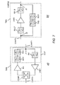
Figure 7 , two systems comprising the device DEV according to the embodiments of the invention are shown schematically. - In
Figure 7 a) a tower mounted bopster TMB may be located between a base station and an antenna system, The tower mounted booster TMB is preferably located at a top of an antenna most next to the antenna system. The tower mounted booster TMB is preferably used for compensate of feeder cable losses, for boosting cell coverage e.g. along coastlines, or for boosting up low power signals from low power base stations such as a micro BTS (BTS = base transceiver station). - The tower mounted booster TMB may be connected to the antenna system via an antenna connection C-ANT1 and may be connected to a base station cabinet via a base station connection G-BTS1.
- The tower mounted booster TMB may comprise a duplexer DUP, a coupler COUP, a power amplifier PA, and a low noise amplifier LNA1,
- A received signal coming from the antenna system is delivered to a receiving path of the tower mounted booster TMB via a junction J1, is filtered by a receive filter RX of the duplexer DUP and amplified by the low-noise amplifier LNA1 and is coupled to the base station connection C-BTS1 via the coupler COUP.
- A transmit signal coming from the base station cabinet is coupled to a transmit path of the tower mounted booster TMB via the coupler COUP, is amplified by the power amplifier PA, is filtered by the device DEV being for example a coaxial low-pas, filter, is further filtered by a transmit filter TX1 and is delivered to the antenna connection C-ANT1 via the junction J1.
- In further alternatives, the device DEV may be located for example at an end of the antenna connection C-ANT1 next to the antenna system or between a feeder cable and a jumper cable of the base station connection C-BTS1.
- In
Figure 7 b) a tower mounted amplifier TMA may be located between a base station and an antenna system. The tower mounted amplifier TMA is preferably located at a top of an antenna mast next to the antenna system. The tower mounted amplifier TMA is preferably used for reducing a base station noise figure and thereby can improve an overall receiver sensitivity to be able to receive weaker radio frequency signals. - The tower mounted amplifier TMA may be connected to the antenna system via an antenna connection C-ANT2 and may be connected to a base station cabinet via a base station connection C-BTS2.
- The tower mounted amplifier TMA may comprise a first receive filter RX_F, a low noise amplifier LNA2, and a second receive filter RX_B in a receive path and the device DEV being for example a coaxial low-pass filter and a transmit filter TX2 in a transmit path.
- The receive path and the transmit path are splitted and combined by two junctions J2, J3.
- In further alternatives, the device DEV may be located for example at an end of the antenna connection C-ANT2 next to the antenna system or between a feeder cable and a jumper cable of the base station connection C-BTS2.
- In even further alternatives, the device DEV may be used in duplex filters for base stations, in receive paths of radio communication systems or in transmission systems for radio frequency signals at a junction between two cables of the transmission systems.
- Using the device DEV according to the embodiments of the invention, a spectral characteristic of the transmit signal passing the tower mounted booster TMB or the tower mounted amplifier TMA can be improved. Furthermore, the invention allows for a smaller required space for the device DEV within the housings of the duplexer DUP, the tower mounted booster TMB, or the tower mounted amplifier TMA and thereby may reduce manufacturing costs.
- The invention is not limited to an application of a single embodiment in systems such as the tower mounted booster TMB or the tower mounted amplifier TMA but also can be used by combining of several of the embodiments of the invention in such systems.
Claims (14)
- A device (DEV) comprising means for filtering radio frequency signals and means for suppressing resonances, said means for filtering comprise at least one capacitive means (CAP_M2_2, CAP_M3_2, CAP_M2_3, CAP_M3_3, CAP_M2_4, CAP_M3_4, CAP_M2_5, CAP_M2_6, CAP_M2_7),
wherein said at least one capacitive means (CAP_M2_2, CAP_M3_2, CAP_M2_3, CAP_M3_3, CAP_M2_4, CAP_M3_4, CAP_M2_5, CAP_M2_6, CAP_M2_7) is adapted for providing said means for suppressing said resonances. - Device according to claim 1, wherein said capacitive means (CAP_M2_2, GAP_M3_2, CAP_2_3, CAP_M3_3, CAP_M2_4, CAP_M3_4, CAP_M2_5, CAP_M2_6, CAP_M2_7) is adapted at a border area of said capacitive means (CAP_M2_2, CAP_M3_2, CAP_M2_3, CAP_M3_3, CAP_M2_4, CAP_M3_4, CAP_M2_5, CAP_M2_6, CAP_M2_7).
- Device according to claim 1 or claim 2, wherein said at least one capacitive means (GAP_M2_2, CAP_M3_2, CAP_M2_3, CAP_M3_3, CAP_M2_4, CAP_M3_4) is adopted by adapting a form of said at least one capacitive means (CAP_M2_2, CAP_M3_2, CAP_M2_3; CAP_M3_3, CAP_M2_4, CAP_M3_4).
- Device according to claim 3, wherein said form comprises a solid body with at least one notch (SLT1, SLT2, SLT3, SLT4, SLT5, SLT6).
- Device according to claim 4, wherein said at least one notch (SLT1, SLT2, SLT3, SLT4, SLT5, SLT6) is arranged in a radial direction.
- Device according to claim 3, wherein said form comprises a solid body with at least one opening (OP1, OP2, OP3, OP4, OP5, OF6).
- Device according to claim 4 or claim 6, wherein a number and a size of said at least one notch (SLT1, SLT2, SLT3, SLT4, SLT5, SLT6) or said at least one opening (OP1, OP2, OP3, OP4, OP5, OP6) is adopted to a predefined capacitance of said at least one capacitive means (CAP_M2_2, CAP_M3_2, CAP_M2_3, CAP_M3_3, CAP_M2_4, CAP_M3_4).
- Device according to claim 3, wherein a cross section of said form comprises a first segment (SEG2_4_1; SEG3_4_1) and at least one second segment (SEG2_4_2, SEG3_4_2), and wherein a radial distance (RAD_DIS1) or an average radial distance of a border of said first segment (SEG2_4_1, SEG3_4_1) is larger than a radial distance (RAD_DIS2) or an average radial distance of a border of said at least one second segment (SEG2_4_2, SEG3_4_2).
- Device according to claim 1 or claim 2, wherein said at least one capacitive means (CAP_M2_5, CAP_M2_6, CAP_M2_7) is adapted by adapting a composition of said at least one capacitive means (CAP_M2_5, CAP_M2_6, CAP_M2_7).
- Device according to claim 9, wherein a cross section of said at least one capacitive means (CAP_M2_5, CAP_M2_6, CAP_M2_7) comprises a first segment (SEG2_5_1, SEG2_6_1, SEG2_7_1) and at least one second segment (SEG2_5_2, SEG2_5_3, SEG2_5_4, SEG2_6_2, SEG2_6_3, SEG2_6_4, SEG2_7_2), and wherein said first segment (SEG2_5_1, SE02_6_1, SEG2_7_1) comprises at least one conductive material and said at least one second segment (SEQ2_5_2, SEG2_5_3, SEG2_5_4, SEG2_6_2, SEG2_6_3, SEG2_6_4, SEG2_7_2) comprises at least one dielectric material.
- Device according to claim 1 0 and claim 4 or claim 6, wherein said at least one opening (OP1, OP2, OP3, OP4, OP5, OP6) or said at least one notch (SLT1, SLT2, SLT3, SLT4, SLT5, SLT6) is filled with said at least one dielectric material.
- Device according to any of the preceding claims, wherein said device (DEV) is a coaxial filter.
- Device according to any of the preceding claims, wherein said device (DEV) is a low-pass filter.
- A system (TMB, TMA) comprising a device (DEV) according to any of the preceding claims.
Priority Applications (1)
| Application Number | Priority Date | Filing Date | Title |
|---|---|---|---|
| EP09305769A EP2287964A1 (en) | 2009-08-19 | 2009-08-19 | Device for filtering radio frequency signals and system thereof |
Applications Claiming Priority (1)
| Application Number | Priority Date | Filing Date | Title |
|---|---|---|---|
| EP09305769A EP2287964A1 (en) | 2009-08-19 | 2009-08-19 | Device for filtering radio frequency signals and system thereof |
Publications (1)
| Publication Number | Publication Date |
|---|---|
| EP2287964A1 true EP2287964A1 (en) | 2011-02-23 |
Family
ID=41202608
Family Applications (1)
| Application Number | Title | Priority Date | Filing Date |
|---|---|---|---|
| EP09305769A Withdrawn EP2287964A1 (en) | 2009-08-19 | 2009-08-19 | Device for filtering radio frequency signals and system thereof |
Country Status (1)
| Country | Link |
|---|---|
| EP (1) | EP2287964A1 (en) |
Cited By (2)
| Publication number | Priority date | Publication date | Assignee | Title |
|---|---|---|---|---|
| CN109428140A (en) * | 2017-08-30 | 2019-03-05 | 凯瑟雷恩欧洲股份公司 | Coaxial filter |
| JP2021532612A (en) * | 2019-06-19 | 2021-11-25 | 韓 宇南HAN, Yunan | Filter cable |
Citations (5)
| Publication number | Priority date | Publication date | Assignee | Title |
|---|---|---|---|---|
| GB605253A (en) * | 1944-12-21 | 1948-07-19 | Sperry Gyroscope Co Inc | Improvements in and relating to concentric-conductor transmission lines |
| FR2380646A1 (en) * | 1977-02-14 | 1978-09-08 | Murata Manufacturing Co | HYPERFREQUENCY FILTER |
| JPS57148402A (en) * | 1981-03-11 | 1982-09-13 | Mitsubishi Electric Corp | High frequency filter |
| EP1058336A1 (en) * | 1998-11-12 | 2000-12-06 | Mitsubishi Denki Kabushiki Kaisha | Low-pass filter |
| US20030001697A1 (en) * | 2001-06-20 | 2003-01-02 | The Boeing Company | Resonance suppressed stepped-impedance low pass filter and associated method of fabrication |
-
2009
- 2009-08-19 EP EP09305769A patent/EP2287964A1/en not_active Withdrawn
Patent Citations (5)
| Publication number | Priority date | Publication date | Assignee | Title |
|---|---|---|---|---|
| GB605253A (en) * | 1944-12-21 | 1948-07-19 | Sperry Gyroscope Co Inc | Improvements in and relating to concentric-conductor transmission lines |
| FR2380646A1 (en) * | 1977-02-14 | 1978-09-08 | Murata Manufacturing Co | HYPERFREQUENCY FILTER |
| JPS57148402A (en) * | 1981-03-11 | 1982-09-13 | Mitsubishi Electric Corp | High frequency filter |
| EP1058336A1 (en) * | 1998-11-12 | 2000-12-06 | Mitsubishi Denki Kabushiki Kaisha | Low-pass filter |
| US20030001697A1 (en) * | 2001-06-20 | 2003-01-02 | The Boeing Company | Resonance suppressed stepped-impedance low pass filter and associated method of fabrication |
Cited By (4)
| Publication number | Priority date | Publication date | Assignee | Title |
|---|---|---|---|---|
| CN109428140A (en) * | 2017-08-30 | 2019-03-05 | 凯瑟雷恩欧洲股份公司 | Coaxial filter |
| US11245167B2 (en) | 2017-08-30 | 2022-02-08 | Telefonaktiebolaget Lm Ericsson (Publ) | Coaxial filter |
| CN109428140B (en) * | 2017-08-30 | 2022-04-29 | 瑞典爱立信有限公司 | Coaxial filter |
| JP2021532612A (en) * | 2019-06-19 | 2021-11-25 | 韓 宇南HAN, Yunan | Filter cable |
Similar Documents
| Publication | Publication Date | Title |
|---|---|---|
| US7057483B2 (en) | High-frequency circuit device and high-frequency circuit module | |
| US11374296B2 (en) | Ceramic filter using stepped impedance resonators having an inner cavity with a decreasing inner diameter provided by a plurality of tapers | |
| JP2918352B2 (en) | Spatial electric field power combiner | |
| CN1274059C (en) | Antenna arrangement | |
| US8704723B2 (en) | Differential dipole antenna system with a coplanar radiating structure and transceiver device | |
| US20070202920A1 (en) | Low noise figure radiofrequency device | |
| JP2008306709A (en) | Slot antenna device | |
| US20070194865A1 (en) | High frequency filter | |
| CN109449585B (en) | Compact high-gain dual-polarization differential filtering antenna | |
| WO2006026826A1 (en) | Multiband filter | |
| CN101237082A (en) | Multi-resistance band and ultra-broadband antenna based on split ring resonancer and mount erosion aperture | |
| WO2002078116A1 (en) | A filter network combining non-superconducting and superconducting filters | |
| US6642902B2 (en) | Low loss loading, compact antenna and antenna loading method | |
| US20110156971A1 (en) | Wide band antenna | |
| US6570472B1 (en) | Low-pass filter | |
| US20060220765A1 (en) | Microwave band-pass filter | |
| EP1755189A1 (en) | Microwave filters with dielectric loads of same height as filter housing | |
| EP2287964A1 (en) | Device for filtering radio frequency signals and system thereof | |
| CN101252218B (en) | Realizing multi-attenuation band ultra-wideband aerial based on two stage type step electric impedance resonator | |
| FI127061B (en) | Control element for radio frequency resonator | |
| CN110459861B (en) | Double-frequency elliptical slot antenna based on substrate integrated waveguide design | |
| CN115296008B (en) | GNSS flexible composite material-based multi-constellation satellite navigation antenna | |
| US9105956B2 (en) | Laminated waveguide diplexer with shielded signal-coupling structure | |
| KR101897625B1 (en) | (BPF(BandPass Filter) using Triple Mode Dielectric Resonator and NRN(Non-resonating node) Stub | |
| AU712921B2 (en) | Field effect transistor amplifier |
Legal Events
| Date | Code | Title | Description |
|---|---|---|---|
| PUAI | Public reference made under article 153(3) epc to a published international application that has entered the european phase |
Free format text: ORIGINAL CODE: 0009012 |
|
| AK | Designated contracting states |
Kind code of ref document: A1 Designated state(s): AT BE BG CH CY CZ DE DK EE ES FI FR GB GR HR HU IE IS IT LI LT LU LV MC MK MT NL NO PL PT RO SE SI SK SM TR |
|
| STAA | Information on the status of an ep patent application or granted ep patent |
Free format text: STATUS: THE APPLICATION IS DEEMED TO BE WITHDRAWN |
|
| RAP1 | Party data changed (applicant data changed or rights of an application transferred) |
Owner name: ALCATEL LUCENT |
|
| 18D | Application deemed to be withdrawn |
Effective date: 20110824 |