EP2283892A2 - Retrieval device for withdrawing a protection device from a body lumen - Google Patents
Retrieval device for withdrawing a protection device from a body lumen Download PDFInfo
- Publication number
- EP2283892A2 EP2283892A2 EP10182878A EP10182878A EP2283892A2 EP 2283892 A2 EP2283892 A2 EP 2283892A2 EP 10182878 A EP10182878 A EP 10182878A EP 10182878 A EP10182878 A EP 10182878A EP 2283892 A2 EP2283892 A2 EP 2283892A2
- Authority
- EP
- European Patent Office
- Prior art keywords
- retrieval
- sheath
- guidewire
- distal
- lumen
- Prior art date
- Legal status (The legal status is an assumption and is not a legal conclusion. Google has not performed a legal analysis and makes no representation as to the accuracy of the status listed.)
- Granted
Links
Images


Classifications
-
- A—HUMAN NECESSITIES
- A61—MEDICAL OR VETERINARY SCIENCE; HYGIENE
- A61F—FILTERS IMPLANTABLE INTO BLOOD VESSELS; PROSTHESES; DEVICES PROVIDING PATENCY TO, OR PREVENTING COLLAPSING OF, TUBULAR STRUCTURES OF THE BODY, e.g. STENTS; ORTHOPAEDIC, NURSING OR CONTRACEPTIVE DEVICES; FOMENTATION; TREATMENT OR PROTECTION OF EYES OR EARS; BANDAGES, DRESSINGS OR ABSORBENT PADS; FIRST-AID KITS
- A61F2/00—Filters implantable into blood vessels; Prostheses, i.e. artificial substitutes or replacements for parts of the body; Appliances for connecting them with the body; Devices providing patency to, or preventing collapsing of, tubular structures of the body, e.g. stents
- A61F2/01—Filters implantable into blood vessels
- A61F2/013—Distal protection devices, i.e. devices placed distally in combination with another endovascular procedure, e.g. angioplasty or stenting
-
- A—HUMAN NECESSITIES
- A61—MEDICAL OR VETERINARY SCIENCE; HYGIENE
- A61B—DIAGNOSIS; SURGERY; IDENTIFICATION
- A61B17/00—Surgical instruments, devices or methods, e.g. tourniquets
- A61B17/22—Implements for squeezing-off ulcers or the like on the inside of inner organs of the body; Implements for scraping-out cavities of body organs, e.g. bones; Calculus removers; Calculus smashing apparatus; Apparatus for removing obstructions in blood vessels, not otherwise provided for
- A61B17/221—Gripping devices in the form of loops or baskets for gripping calculi or similar types of obstructions
-
- A—HUMAN NECESSITIES
- A61—MEDICAL OR VETERINARY SCIENCE; HYGIENE
- A61B—DIAGNOSIS; SURGERY; IDENTIFICATION
- A61B17/00—Surgical instruments, devices or methods, e.g. tourniquets
- A61B2017/00535—Surgical instruments, devices or methods, e.g. tourniquets pneumatically or hydraulically operated
- A61B2017/00539—Surgical instruments, devices or methods, e.g. tourniquets pneumatically or hydraulically operated hydraulically
-
- A—HUMAN NECESSITIES
- A61—MEDICAL OR VETERINARY SCIENCE; HYGIENE
- A61B—DIAGNOSIS; SURGERY; IDENTIFICATION
- A61B17/00—Surgical instruments, devices or methods, e.g. tourniquets
- A61B17/22—Implements for squeezing-off ulcers or the like on the inside of inner organs of the body; Implements for scraping-out cavities of body organs, e.g. bones; Calculus removers; Calculus smashing apparatus; Apparatus for removing obstructions in blood vessels, not otherwise provided for
- A61B2017/22038—Implements for squeezing-off ulcers or the like on the inside of inner organs of the body; Implements for scraping-out cavities of body organs, e.g. bones; Calculus removers; Calculus smashing apparatus; Apparatus for removing obstructions in blood vessels, not otherwise provided for with a guide wire
- A61B2017/22049—Means for locking the guide wire in the catheter
-
- A—HUMAN NECESSITIES
- A61—MEDICAL OR VETERINARY SCIENCE; HYGIENE
- A61B—DIAGNOSIS; SURGERY; IDENTIFICATION
- A61B17/00—Surgical instruments, devices or methods, e.g. tourniquets
- A61B17/22—Implements for squeezing-off ulcers or the like on the inside of inner organs of the body; Implements for scraping-out cavities of body organs, e.g. bones; Calculus removers; Calculus smashing apparatus; Apparatus for removing obstructions in blood vessels, not otherwise provided for
- A61B2017/22051—Implements for squeezing-off ulcers or the like on the inside of inner organs of the body; Implements for scraping-out cavities of body organs, e.g. bones; Calculus removers; Calculus smashing apparatus; Apparatus for removing obstructions in blood vessels, not otherwise provided for with an inflatable part, e.g. balloon, for positioning, blocking, or immobilisation
- A61B2017/22061—Implements for squeezing-off ulcers or the like on the inside of inner organs of the body; Implements for scraping-out cavities of body organs, e.g. bones; Calculus removers; Calculus smashing apparatus; Apparatus for removing obstructions in blood vessels, not otherwise provided for with an inflatable part, e.g. balloon, for positioning, blocking, or immobilisation for spreading elements apart
-
- A—HUMAN NECESSITIES
- A61—MEDICAL OR VETERINARY SCIENCE; HYGIENE
- A61B—DIAGNOSIS; SURGERY; IDENTIFICATION
- A61B17/00—Surgical instruments, devices or methods, e.g. tourniquets
- A61B17/22—Implements for squeezing-off ulcers or the like on the inside of inner organs of the body; Implements for scraping-out cavities of body organs, e.g. bones; Calculus removers; Calculus smashing apparatus; Apparatus for removing obstructions in blood vessels, not otherwise provided for
- A61B17/221—Gripping devices in the form of loops or baskets for gripping calculi or similar types of obstructions
- A61B2017/2212—Gripping devices in the form of loops or baskets for gripping calculi or similar types of obstructions having a closed distal end, e.g. a loop
-
- A—HUMAN NECESSITIES
- A61—MEDICAL OR VETERINARY SCIENCE; HYGIENE
- A61F—FILTERS IMPLANTABLE INTO BLOOD VESSELS; PROSTHESES; DEVICES PROVIDING PATENCY TO, OR PREVENTING COLLAPSING OF, TUBULAR STRUCTURES OF THE BODY, e.g. STENTS; ORTHOPAEDIC, NURSING OR CONTRACEPTIVE DEVICES; FOMENTATION; TREATMENT OR PROTECTION OF EYES OR EARS; BANDAGES, DRESSINGS OR ABSORBENT PADS; FIRST-AID KITS
- A61F2/00—Filters implantable into blood vessels; Prostheses, i.e. artificial substitutes or replacements for parts of the body; Appliances for connecting them with the body; Devices providing patency to, or preventing collapsing of, tubular structures of the body, e.g. stents
- A61F2/01—Filters implantable into blood vessels
- A61F2002/018—Filters implantable into blood vessels made from tubes or sheets of material, e.g. by etching or laser-cutting
-
- A—HUMAN NECESSITIES
- A61—MEDICAL OR VETERINARY SCIENCE; HYGIENE
- A61F—FILTERS IMPLANTABLE INTO BLOOD VESSELS; PROSTHESES; DEVICES PROVIDING PATENCY TO, OR PREVENTING COLLAPSING OF, TUBULAR STRUCTURES OF THE BODY, e.g. STENTS; ORTHOPAEDIC, NURSING OR CONTRACEPTIVE DEVICES; FOMENTATION; TREATMENT OR PROTECTION OF EYES OR EARS; BANDAGES, DRESSINGS OR ABSORBENT PADS; FIRST-AID KITS
- A61F2/00—Filters implantable into blood vessels; Prostheses, i.e. artificial substitutes or replacements for parts of the body; Appliances for connecting them with the body; Devices providing patency to, or preventing collapsing of, tubular structures of the body, e.g. stents
- A61F2/02—Prostheses implantable into the body
- A61F2/30—Joints
- A61F2002/30001—Additional features of subject-matter classified in A61F2/28, A61F2/30 and subgroups thereof
- A61F2002/30003—Material related properties of the prosthesis or of a coating on the prosthesis
- A61F2002/3006—Properties of materials and coating materials
- A61F2002/30092—Properties of materials and coating materials using shape memory or superelastic materials, e.g. nitinol
-
- A—HUMAN NECESSITIES
- A61—MEDICAL OR VETERINARY SCIENCE; HYGIENE
- A61F—FILTERS IMPLANTABLE INTO BLOOD VESSELS; PROSTHESES; DEVICES PROVIDING PATENCY TO, OR PREVENTING COLLAPSING OF, TUBULAR STRUCTURES OF THE BODY, e.g. STENTS; ORTHOPAEDIC, NURSING OR CONTRACEPTIVE DEVICES; FOMENTATION; TREATMENT OR PROTECTION OF EYES OR EARS; BANDAGES, DRESSINGS OR ABSORBENT PADS; FIRST-AID KITS
- A61F2210/00—Particular material properties of prostheses classified in groups A61F2/00 - A61F2/26 or A61F2/82 or A61F9/00 or A61F11/00 or subgroups thereof
- A61F2210/0014—Particular material properties of prostheses classified in groups A61F2/00 - A61F2/26 or A61F2/82 or A61F9/00 or A61F11/00 or subgroups thereof using shape memory or superelastic materials, e.g. nitinol
-
- A—HUMAN NECESSITIES
- A61—MEDICAL OR VETERINARY SCIENCE; HYGIENE
- A61F—FILTERS IMPLANTABLE INTO BLOOD VESSELS; PROSTHESES; DEVICES PROVIDING PATENCY TO, OR PREVENTING COLLAPSING OF, TUBULAR STRUCTURES OF THE BODY, e.g. STENTS; ORTHOPAEDIC, NURSING OR CONTRACEPTIVE DEVICES; FOMENTATION; TREATMENT OR PROTECTION OF EYES OR EARS; BANDAGES, DRESSINGS OR ABSORBENT PADS; FIRST-AID KITS
- A61F2230/00—Geometry of prostheses classified in groups A61F2/00 - A61F2/26 or A61F2/82 or A61F9/00 or A61F11/00 or subgroups thereof
- A61F2230/0002—Two-dimensional shapes, e.g. cross-sections
- A61F2230/0004—Rounded shapes, e.g. with rounded corners
- A61F2230/0006—Rounded shapes, e.g. with rounded corners circular
-
- A—HUMAN NECESSITIES
- A61—MEDICAL OR VETERINARY SCIENCE; HYGIENE
- A61F—FILTERS IMPLANTABLE INTO BLOOD VESSELS; PROSTHESES; DEVICES PROVIDING PATENCY TO, OR PREVENTING COLLAPSING OF, TUBULAR STRUCTURES OF THE BODY, e.g. STENTS; ORTHOPAEDIC, NURSING OR CONTRACEPTIVE DEVICES; FOMENTATION; TREATMENT OR PROTECTION OF EYES OR EARS; BANDAGES, DRESSINGS OR ABSORBENT PADS; FIRST-AID KITS
- A61F2230/00—Geometry of prostheses classified in groups A61F2/00 - A61F2/26 or A61F2/82 or A61F9/00 or A61F11/00 or subgroups thereof
- A61F2230/0063—Three-dimensional shapes
- A61F2230/0067—Three-dimensional shapes conical
-
- A—HUMAN NECESSITIES
- A61—MEDICAL OR VETERINARY SCIENCE; HYGIENE
- A61F—FILTERS IMPLANTABLE INTO BLOOD VESSELS; PROSTHESES; DEVICES PROVIDING PATENCY TO, OR PREVENTING COLLAPSING OF, TUBULAR STRUCTURES OF THE BODY, e.g. STENTS; ORTHOPAEDIC, NURSING OR CONTRACEPTIVE DEVICES; FOMENTATION; TREATMENT OR PROTECTION OF EYES OR EARS; BANDAGES, DRESSINGS OR ABSORBENT PADS; FIRST-AID KITS
- A61F2230/00—Geometry of prostheses classified in groups A61F2/00 - A61F2/26 or A61F2/82 or A61F9/00 or A61F11/00 or subgroups thereof
- A61F2230/0063—Three-dimensional shapes
- A61F2230/0093—Umbrella-shaped, e.g. mushroom-shaped
-
- A—HUMAN NECESSITIES
- A61—MEDICAL OR VETERINARY SCIENCE; HYGIENE
- A61F—FILTERS IMPLANTABLE INTO BLOOD VESSELS; PROSTHESES; DEVICES PROVIDING PATENCY TO, OR PREVENTING COLLAPSING OF, TUBULAR STRUCTURES OF THE BODY, e.g. STENTS; ORTHOPAEDIC, NURSING OR CONTRACEPTIVE DEVICES; FOMENTATION; TREATMENT OR PROTECTION OF EYES OR EARS; BANDAGES, DRESSINGS OR ABSORBENT PADS; FIRST-AID KITS
- A61F2250/00—Special features of prostheses classified in groups A61F2/00 - A61F2/26 or A61F2/82 or A61F9/00 or A61F11/00 or subgroups thereof
- A61F2250/0003—Special features of prostheses classified in groups A61F2/00 - A61F2/26 or A61F2/82 or A61F9/00 or A61F11/00 or subgroups thereof having an inflatable pocket filled with fluid, e.g. liquid or gas
Definitions
- the present invention deals with an emboli capturing system. More specifically, the present invention deals with an emboli capturing system and method for capturing embolic material in a blood vessel during an atherectomy or thrombectomy procedure.
- Blood vessels can become occluded (blocked) or stenotic (narrowed) in one of a number of ways.
- a stenosis may be formed by an atheroma which is typically a harder, calcified substance which forms on the lumen walls of the blood vessel.
- the stenosis can be formed of a thrombus material which is typically much softer than an atheroma, but can nonetheless cause restricted blood flow in the lumen of the blood vessel. Thrombus formation can be particularly problematic in a saphenous vein graft (SVG).
- SVG saphenous vein graft
- stenosis stenotic lesion
- the first is to deform the stenosis to reduce the restriction within the lumen of the blood vessel. This type of deformation (or dilatation) is typically performed using balloon angioplasty.
- Another method of treating stenotic vasculature is to attempt to completely remove either the entire stenosis, or enough of the stenosis to relieve the restriction in the blood vessel. Removal of the stenotic lesion has been done through the use of radio frequency (RF) signals transmitted via conductors, and through the use of lasers, both of which treatments are meant to ablate (i.e., super heat and vaporize) the stenosis. Removal of the stenosis has also been accomplished using thrombectomy or atherectomy. During thrombectomy and atherectomy, the stenosis is mechanically cut or abraded away from the vessel.
- RF radio frequency
- the stenotic debris which is separated from the stenosis is free to flow within the lumen of the vessel. If the debris flows distally, it can occlude distal vasculature and cause significant problems. If it flows proximally, it can enter the circulatory system and form a clot in the neural vasculature, or in the lungs, both of which are highly undesirable.
- a final technique for dealing with the fragments of the stenosis which are severed during atherectomy is to place a device distal to the stenosis during atherectomy to catch the pieces of the stenosis as they are severed, and to remove those pieces along with the capturing device when the atherectomy procedure is complete.
- capture devices have included expandable filters which are placed distal of the stenosis to capture stenosis fragments. Problems are also associated with this technique. For example, delivery of such devices in a low profile, predeployment configuration can be difficult. Further, some devices include complex and cumbersome actuation mechanisms. Also, retrieving such capture devices, after they have captured emboli, can be difficult as well.
- An emboli capturing system captures emboli in a body lumen.
- a first elongate member has a proximal end and a distal end.
- An expandable emboli capturing device is mounted proximate the distal end of the first elongate member, and is movable between a radially expanded position and a radially contracted position. When in the expanded position, the emboli capturing device forms a basket with a proximally opening mouth.
- a second elongate member has a proximal and a distal end with a lumen extending therebetween. The lumen is sized to slidably receive a portion of the first elongate member.
- An expandable delivery device is mounted to the distal end of the second elongate member and is movable from a radially retracted position to a radially expanded position.
- the delivery device has a receiving end configured to receive the emboli capturing device, and retains at least the mouth of the emboli capturing device in a radially retracted position.
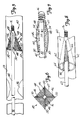
- FIG. 1 illustrates protection device 10 in a deployed position within the lumen of a blood vessel 12.
- Protection device 10 preferably includes hollow guidewire 14 (or a hypotube having the same general dimensions as a guidewire) having a coil tip 16, and a capturing assembly 18.
- Capturing assembly 18, in the embodiment shown in FIG. 1 includes an inflatable and expandable member 20 and mesh 22.
- expandable member 20 is preferably coupled for fluid communication with an inner lumen of guidewire 14 at a distal region of guidewire 14.
- inflatable member 20 When deployed, inflatable member 20 inflates and expands to the position shown in FIG. 1 such that capturing assembly 18 has an outer periphery which approximates the inner periphery of lumen 12.
- Mesh 22 is preferably formed of woven or braided fibers or wires, or a microporous membrane, or other suitable filtering or netting-type material.
- mesh 22 is a microporous membrane having holes therein with a diameter of approximately 100 ⁇ m.
- Mesh 22 can be disposed relative to inflatable member 20 in a number of different ways.
- mesh 22 can be formed of a single generally cone-shaped piece which is secured to the outer or inner periphery of inflatable member 20.
- mesh 22 can be formed as a spiral strip which is secured about the outer or inner periphery of inflatable member 20 filling the gaps between the loops of inflatable member 20.
- mesh 22 can be formed of a number of discrete pieces which are assembled onto inflatable member 20.
- Hollow guidewire 14 preferably has a valve 24 coupled in a proximal portion thereof.
- a syringe is preferably connected to the proximal end of guidewire 14, which preferably includes a fluid hypotube.
- the syringe is used to pressurize the fluid such that fluid is introduced through the lumen of hollow guidewire 14, through valve 24, and into inflatable member 20.
- inflatable member 20 Upon being inflated, inflatable member 20 expands radially outwardly from the outer surface of guidewire 14 and carries mesh 22 into the deployed position shown in FIG. 1 .
- capturing assembly, or filter assembly, 18 is deployed distally of stenosis 26 so that stenosis 26 can be severed and fragmented, and so the fragments from stenosis 26 are carried by blood flow (indicated by arrow 28) into the basket or chamber formed by the deployed filter assembly 18.
- Filter assembly 18 is then collapsed and removed from vessel 12 with the fragments of stenosis 26 contained therein.
- FIG. 2 illustrates protection device 10 with filter assembly 18 in the collapsed position. Similar items to those shown in FIG. 1 are similarly numbered.
- FIG. 2 illustrates that mesh 22 is easily collapsible with inflatable member 20.
- fluid is preferably removed from inflatable member 20 through the lumen of hollow guidewire 14 and through two-way valve 24. This can be done using the syringe to pull a vacuum, or using any other type of suitable fluid removal system.
- Inflatable member 20 is preferably formed of a material having some shape memory. Thus, when inflatable member 20 is collapsed, it collapses to approximate the outer diameter of hollow guidewire 14.
- inflatable member 20 is formed of a resilient, shape memory material such that it is inflated by introducing fluid under pressure through the lumen in hollow guidewires 14 into inflatable member 20. When pressure is released from the lumen in hollow guidewire 14, inflatable member 20 is allowed to force fluid out from the interior thereof through two-way valve 24 and to resume its initial collapsed position. Again, this results in filter assembly 18 assuming its collapsed position illustrated in FIG. 2 .
- FIG. 3 illustrates a view taken from the distal end of device 10 with mesh 22 removed for clarity.
- FIG. 3 shows that, when inflatable member 20 is deployed outwardly, mesh 22 (when deployed between the loops of inflatable member 20) forms a substantially lumen-filling filter which allows blood to flow therethrough, but which provides a mechanism for receiving and retaining stenosis fragments carried into mesh 22 by blood flow through the vessel.
- FIG. 3 also shows that inflatable member 20 preferably has a proximal end portion 29 which is connected to the outer periphery of guidewire 14. Although end 29 need not be connected to guidewire 14, it is preferably connected using adhesive or any other suitable connection mechanism. By fixedly connecting proximal end portion 29 to guidewire 14, this increases the stability of the filter assembly 18 upon deployment.
- FIG. 4 is a cross-sectional view of a portion of protection device 10.
- FIG. 4 shows protection device 10 with filter assembly 18 in the expanded or deployed position.
- FIG. 4 also better illustrates that guidewire 14 is hollow and has a longitudinal lumen 30 extending therethrough. Longitudinal lumen 30 is connected in fluid communication with an interior of inflatable member 20 through aperture 32 which is provided in the wall of guidewire 14.
- FIG. 4 also shows that, in one preferred embodiment, a core wire 34 extends through lumen 30 from a proximal end thereof where it is preferably brazed to a portion of a hypotube which may be connected to the proximal portion of guidewire 14.
- the core wire 34 extends to the distal end of guidewire 14 where it is connected to coil tip 16.
- coil tip 16 is brazed or otherwise welded or suitably connected to the distal portion of core wire 34.
- FIG. 4 further shows that, in the preferred embodiment, inflatable member 20 inflates to a generally helical, conical shape to form a basket opening toward the proximal end of guidewire 14.
- FIG. 4 further illustrates, in the preferred embodiment, mesh 22 has a distal portion 38 which is connected to the exterior surface of guidewire 14, at a distal region thereof, through adhesive 36 or any other suitable connection mechanism.
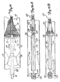
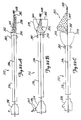
- FIG. 5 illustrates a second embodiment of a distal protection device 40 in accordance with the present invention.
- Device 40 includes hollow guidewire 42, filter assembly 44 and coil tip 16.
- Filter assembly 44 includes a plurality of inflatable struts 46 and mesh 47.
- Each strut 46 has a distal end 48 and proximal end 50.
- Inflatable struts 46 also have an interior which is coupled in fluid communication, through distal end 48 thereof, with the lumen in hollow guidewire 42.
- Struts 46 are preferably configured such that, upon being inflated, the proximal ends 50 deploy radially outwardly away from the outer surface of hollow guidewire 42 to assume a dimension which approximates the inner dimension of lumen 58 in which they are inserted.
- Mesh 47 is deployed either on the outer or inner surface of inflatable struts 46, such that, when the inflatable struts 46 are deployed radially outwardly, mesh 47 forms a generally conical basket opening toward the proximal end of hollow guidewire 42.
- mesh 47 can be applied to either the outer or the inner surface of struts 46. It can be applied to struts 46 as one unitary conical piece which is adhered about distal ends 48 of struts 46 using adhesive (or about the distal end of guidewire 42 using adhesive) and secured to the surface of the struts 46 also using adhesive. Alternatively, mesh 47 can be applied to struts 46 in a plurality of pieces which are individually or simultaneously secured to, and extend between, struts 46.
- FIG. 6 is an end view of distal protection device 40 shown in FIG. 5 taken from the distal end of distal protection device 40.
- mesh 47 forms a substantially lumen-filling filter which allows blood to flow therethrough, but which provides a mechanism for receiving and retaining stenosis fragments from stenosis 56 carried into mesh 47 by blood flow through the vessel.
- FIG. 7 is a cross-sectional view of a portion of distal protection device 40 shown in FIGS. 5 and 6.
- FIG. 7 shows filter assembly 44 in the collapsed position in which it approximates the outer diameter of guidewire 42.
- FIG. 7 also shows that, in the preferred embodiment, the distal ends 48 of struts 46 are in fluid communication with an inner lumen 52 in hollow guidewire 42 through apertures 54 in the wall of guidewire 42.
- FIG. 8 illustrates another embodiment of a distal protection device 60 in accordance with the present invention.
- Distal protection device 60 is similar to those shown in other figures, and similar items are similarly numbered.
- distal protection device 60 includes hollow guidewire 63 which has a lumen in fluid communication with an interior of a pair of inflatable struts 62.
- Inflatable struts 62 have an inner surface 64 which is generally concave, or hemispherical, or otherwise appropriately shaped such that it extends about a portion of the outer surface of hollow guidewire 63.
- Mesh portions 66 extend between the inflatable struts 62 so that inflatable struts 62 and mesh portions 66, when deployed outwardly as shown in FIG. 8 , form a basket shape which opens toward the proximal end of hollow guidewire 63.
- FIG. 9 illustrates another system for attaching inflatable struts to a hollow guidewire for a distal protection device 70 in accordance with the present invention.
- Distal protection device 70 is similar to the distal protection devices shown in the previous figures in that a plurality of inflatable struts 72 are provided and preferably have a mesh portion extending therebetween. For the sake of clarity, the mesh portion is eliminated from FIG. 9 . However, it will be understood that, when deployed, distal protection device 70 forms a generally basket-shaped filter assembly which opens toward the proximal end of hollow guidewire 74.
- hollow guidewire 74 has a distal end 75 which is open.
- An endcap 76 is disposed about the distal end 75 of hollow guidewire 74 and defines an internal chamber or passageway 78.
- Endcap 76 has a proximal end 80 which has openings therein for receiving the ends of inflatable struts 72.
- the operator pressurizes fluid within the lumen of hollow guidewire 74 forcing fluid out through distal end 75 of hollow guidewire 74, through passageway 78, and into inflatable struts 72.
- the operator draws a vacuum which pulls the fluid back out of inflatable struts 72, through passageway 78 and, if necessary, into the lumen of hollow guidewire 74.
- FIG. 10 is an end view of endcap 76 taken along lines 10-10 in FIG. 9.
- proximal end 80 of endcap 76 preferably includes a first generally central aperture 82 for receiving the distal end of hollow guidewire 74.
- Aperture 82 is sized just larger than, or approximating, the outer diameter of hollow guidewire 74 such that it fits snugly over the distal end 75 of hollow guidewire 74.
- Endcap 76 is then fixedly connected to the distal end 75 of hollow guidewire 74 through a friction fit, a suitable adhesive, welding, brazing, or another suitable connection technique.
- FIG. 10 also shows that proximal end 80 of endcap 76 includes a plurality of apertures 84 which are spaced from one another about end 80. Apertures 84 are sized to receive open ends of inflatable struts 72. In the preferred embodiment, inflatable struts 72 are secured within apertures 84 using a suitable adhesive, or another suitable connection technique. Also, in the preferred embodiment, spring tip 16 is embedded in, or otherwise suitably connected to, endcap 76.
- FIGS. 11A and 11B show two other preferred embodiments of a distal protection device in accordance with the present invention.
- FIG. 11A shows distal protection device 90 which includes hollow guidewire 92 having a lumen running therethrough, inflatable member 94 and mesh portion 96.
- FIG. 11A shows that inflatable member 94, when inflated, forms a ring about the outer surface of hollow guidewire 92.
- the ring has an inner periphery 98 which is spaced from the outer surface of hollow guidewire 92 substantially about the entire radial periphery of hollow guidewire 92.
- Mesh portion 96 extends between the outer surface of hollow guide 92 and the inner periphery 98 of inflatable member 94.
- deployment of distal protection device 90 is accomplished by providing fluid through the inner lumen of hollow guidewire 92 into an interior of inflatable member 94 which is in fluid communication with the inner lumen of hollow guidewire 92.
- end 100 of inflatable member 94 is coupled to a coupling portion 102 of inflatable member 94 such that stability is added to inflatable member 94, when it is inflated.
- FIG. 11B illustrates another distal protection device 104 which includes a hollow guidewire 106 and an inflatable member 108.
- Device 104 is similar to distal protection device 90 except that, rather than having only a single inflatable ring upon deployment of distal protection device 104, a plurality of generally equal-diameter rings are formed into a helix shape.
- distal protection device 104 includes a mesh sleeve 110 which extends about the outer or inner surface of the helix formed by inflatable member 108.
- mesh sleeve 110 is connected to the outer surface of hollow guidewire 106 in a region 112 proximate, but distal of, inflatable member 108.
- distal protection device 104 forms a generally basket-shaped filter assembly which opens toward a proximal end of guidewire 106.
- both distal protection device 90 shown in FIG. 11A and distal protection device 104 shown in FIG. 11B are preferably collapsible. Therefore, when collapsed, the distal protection devices 90 and 104. preferably have an outer dimension which approximates the outer dimension of hollow guidewires 92 and 106, respectively. Further, as with the other embodiments, distal protection devices 90 and 104 can either be biased in the deployed or collapsed positions, and deployment and collapse can be obtained either by pulling a vacuum, or pressurizing the fluid within the lumen of the hollow guidewires 92 and 106.
- FIG. 12 illustrates the use of a distal protection device in accordance with the present invention.
- Device 10 is shown filtering stenosis fragments from the blood flowing through the lumen of vessel 12.
- FIG. 12 also shows a dilatation device 120 which can be any suitable dilatation device for dilating, cutting, fragmenting, or abrading, portions of stenosis 26.
- device 120 is used in an over-the-wire fashion over hollow guidewire 14.
- filter assembly 18 is first advanced (using guidewire 14) distal of stenosis 26. Then, filter assembly 18 is deployed outwardly to the expanded position.
- Dilatation device 120 is then advanced over guidewire 14 to stenosis 26 and is used to fragment or abrade stenosis 26. The fragments are received within the basket of filter assembly 18. Filter assembly 18 is then collapsed, and filter assembly 18 and dilatation device 120 are removed from vessel 12. Alternatively, dilatation device 120 can be removed first and filter assembly 18 is then removed along with guidewire 14.
- the stenosis removal device (or atherectomy catheter) 120 used to fragment stenosis 26 can be advanced over guidewire 14. Therefore, the device according to the present invention is dual functioning in that it captures emboli and serves as a guidewire. The present invention does not require adding an additional device to the procedure. Instead, the present invention simply replaces a conventional guidewire with a multi-functional device.
- FIGS. 13A-17B illustrate embodiments of various distal protection devices wherein deployment and contraction of the distal protection device is accomplished through a mechanical push/pull arrangement.
- FIGS. 13A and 13B illustrate a distal protection device 122.
- FIG. 13A shows device 122 in an undeployed position and FIG. 13B shows device 122 in a deployed position.
- Distal protection device 122 includes a slotted Nitinol tube 124 which has a lumen 126 extending therethrough. Tube 124 has a plurality of slots 128 at a distal region thereof. The distal portion of slots 128 are covered by mesh 130 which, in the preferred embodiment, is a flexible microporous membrane.
- Device 122 also preferably includes a mandrel 132 which extends through the inner lumen 126 of tube 124 and is attached to the distal end of tube 124.
- mandrel 132 is attached to the distal end of tube 124 by an appropriate adhesive, brazing, welding, or another suitable connection technique.
- Tube 124 also has, on its inner periphery in a proximal region thereof, a plurality of locking protrusions 134. Lock protrusions 134 are preferably arranged about a proximal expandable region 136 disposed on mandrel 132.
- tube 124 In order to deploy device 122 into the deployed position shown in FIG. 13B , the operator preferably first advances tube 124 distally of the lesion to be fragmented.
- tube 124 has a size on the order of a guidewire, such as a 0.014 inch outer diameter. Therefore, it easily advances beyond the stenosis to be fragmented.
- the operator then pushes on the proximal region of tube 124 and pulls on the proximal end of mandrel 132. This causes two things to happen. First, this causes the struts formed by slots 128 to expand radially outwardly, and carry with them, microporous membrane 130.
- microporous membrane 130 forms a generally basket-shaped filter assembly which opens toward the proximal end of tube 124.
- proximal expandable member 136 expands and engages protrusions 134. This locks device 122 in the deployed and expanded position.
- the physician simply pushes on mandrel 132 and pulls on the proximal end of tube 124. This causes device 122 to return to the undeployed position shown in FIG. 13A .
- device 122 can optionally be provided with a stainless steel proximal hypotube attachment.
- the struts defined by slots 128 can be expanded and retracted using a fluid coupling instead of a mandrel.
- the proximal end of tube 124 can be coupled to a pressurizable fluid source.
- FIG. 14A illustrates distal protection device 140 which is similar to that shown in FIGS. 13A and 13B , except that the struts 142 are formed of a metal or polymer material and are completely covered by mesh 144.
- Mesh 144 includes two mesh portions, 146 and 148.
- Mesh portion 146 is proximal of mesh portion 148 on device 140 and is a relatively loose mesh which will allow stenosis fragments to pass therethrough.
- mesh 148 is a fairly tight mesh, or a microporous membrane, (or simply loose mesh portion 146 with a microporous membrane or other suitable filter material bonded or cast or otherwise disposed thereover) which does not allow the fragments to pass therethrough and therefore captures and retains the fragments therein.
- the mesh portions can provide a memory set which, in the relaxed position, is either deployed or collapsed.
- FIG. 14B illustrates a device 150 which is similar to device 140 shown in FIG. 14A , except struts 142 are eliminated and the two mesh portions 146' and 148' are simply joined together at a region 152. Also, the two mesh portions 146' and 148' are not two different discrete mesh portions but are formed of the same braided mesh material wherein the braid simply has a different pitch. The wider pitch in region 146' provides a looser mesh, whereas the narrower pitch in region 148' provides a tighter mesh that traps the embolic material.
- FIG. 14C illustrates a distal protection device 160 which is similar to that shown in FIG. 14A .
- distal protection device 160 includes a plurality of struts 162 on a proximal region thereof and a plurality of struts 164 on the distal region thereof.
- Struts 162 are spaced further apart than struts 164 about the periphery of protection device 160. Therefore, struts 162 define openings 166 which are larger than the openings 168 defined by struts 164 and allow stenosis fragments to pass therethrough.
- struts 164 have secured to the interior surface thereof a filter or mesh portion 170. When deployed, filter portion 170 forms a substantially basket-shaped filter device opening toward the proximal region of tube 172.
- FIG. 15 illustrates the operation of another distal protection device 176.
- Distal protection device 176 includes a tube 178 and a push/pull wire 180.
- Tube 178 has, at the distal end thereof, a filter assembly 182.
- Filter assembly 182 includes a plurality of preferably metal struts 184 which have a microporous membrane, or other suitable mesh 186 disposed thereon.
- Tube 178 also preferably includes end cap 188 and umbrella-like expansion structure 190 disposed at a distal region thereof.
- Expansion structure 190 is connected to the distal region of tube 178 and to metal struts 184 such that, when push/pull wire 180 is pulled relative to tube 178, expansion member 190 exerts a radial, outwardly directed force on struts 184 causing them to expand radially outwardly relative to the outer surface of tube 178.
- This causes microporous membrane or mesh 186 to be deployed in a manner opening toward the proximal end of tube 178 to catch embolic material.
- Struts 184 can also be formed of an appropriate polymer material.
- FIGS. 16A and 16B illustrate a protection device in accordance with another embodiment of the present invention.
- FIG. 16A illustrates distal protection device 192.
- Device 192 includes guidewire 194, actuator wire 196, and filter assembly 198.
- Filter assembly 198 includes an expandable ring 200, such as an expandable polymer or metal or other elastic material, which has attached thereto mesh 202.
- Mesh 202 is also attached to guidewire 194 distally of ring 200.
- Actuator wire 196 is attached to sleeve or sheath 204 which is positioned to fit about the outer periphery of expandable ring 200, when expandable ring 200 is in the collapsed position.
- expandable ring 200 when sheath 204 is moved distally of expandable ring 200, expandable ring 200 has shape memory which causes it to expand into the position shown in FIG. 16A .
- actuator wire 196 when sheath 204 is pulled proximally by pulling actuator wire 196 relative to guidewire 194, sheath 204 collapses ring 200 and holds ring 200 in the collapsed position within sheath 204.
- Manipulating wires 194 and 196 relative to one another causes device 192 to move from the deployed position to the collapsed position, and vice versa.
- FIG. 16B is similar to device 192 except that, instead of having an expandable ring 200 connected at one point to wire 194, distal protection device 206 includes expandable member 208 which is formed of an elastic coil section of wire 194.
- elastic coil section 208 has a shape memory which causes it to expand into the generally helical, conical shape shown in FIG. 16B .
- sheath 204 is pulled proximally relative to expandable member 208, this causes sheath 204 to capture and retain expandable member 208 in a collapsed position.
- expandable member 208 returns to its expanded position shown in FIG. 16B carrying with it mesh 210 into a deployed position.
- sheath 204 is formed of a suitable polymer material and expandable member 208 and expandable ring 200 are preferably formed of Nitinol.
- FIGS. 17A and 17B illustrate the operation of another distal protection device 212.
- Protection device 212 includes guidewire 214 and filter assembly 216.
- filter assembly 216 includes a wire braid portion 218 which extends from a distal region of guidewire 214 proximally thereof.
- Braid portion 218 is formed of braided filaments or fibers which have a shape memory causing them to form a deployed, basket-shaped filter, such as that shown in FIG. 17A , in the unbiased position.
- Braided portion 218 terminates at its proximal end in a plurality of eyelets 220.
- One or more cinch wires 222 are preferably threaded through eyelets 220.
- the operator holds mesh 218 in the collapsed position and inserts protection device 212 distally of the desired stenosis.
- the operator then allows cinch wire 222 to move distally relative to guidewire 214.
- This allows mesh 218 to open to the deployed position shown in FIG. 17A which has an outer diameter that approximates the inner diameter of the lumen within which it is disposed.
- Filter assembly 216 is then disposed to capture embolic material from blood flowing therethrough. Once the embolic material is captured, the operator again moves cinch wire 222 proximally relative to guidewire 214 to collapse filter assembly 216 and capture and retain the embolic material in filter assembly 216. The device 212 is then removed.
- FIG. 17B shows distal protection device 212 except that in the embodiment shown in FIG. 17B , protection device 212 is not disposed distally of the stenosis, but rather proximally. This results, for example, in an application where the blood flow is proximal of the stenosis rather than distal.
- guidewire 214 is preferably hollow and the cinch wire 222 extends through the lumen therein. By pushing on guidewire 214, a force is exerted on mesh 218 in the distal direction. This causes cinch wire 222 to tightly close the distal opening in filter assembly 216 and to collapse mesh portion 218. By contrast, by allowing cinch wire 222 to move distal relative to hollow guidewire 214, mesh portion 218 expands and filter assembly 216 is deployed as shown in FIG. 17B .
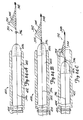
- FIGS. 18A and 18B illustrate a distal protection device 250 in accordance with another aspect of the present invention.
- Device 250 includes inner wire 252 and outer tube 254.
- inner wire 252 is a core wire and outer tube 254 has a lumen 256 therein large enough to accommodate longitudinal movement of inner wire 252 therein.
- inner wire 252 has, coupled to its distal end 258, a spring tip 260.
- Expandable portion 262 has a proximal end 264 which is attached to the distal end 266 of tube 254. Also, expandable member 262 has a distal end 268 which is attached to the distal end 258 of inner wire 252.
- Expandable member 262 is preferably a mesh or braided material which is coated with polyurethane.
- a distal portion of expandable member 262 has a tighter mesh than a proximal portion thereof, or has a microporous membrane or other suitable filtering mechanism disposed thereover.
- expandable member 262 is simply formed of a tighter mesh or braided material which, itself, forms the filter.
- FIG. 18A illustrates device 250 in a collapsed, or insertion position wherein the outer diameter of mesh portion 262 closely approximates the outer diameters of either inner wire 252 or outer tube 254.
- FIG. 18B illustrates device 250 in the deployed position in which expandable member 262 is radially expanded relative to the collapsed position shown in FIG. 18A .
- the outer tube 254 is moved distally with respect to inner wire 252 such that the distal ends 266 and 258 of wires 254 and 252 move longitudinally toward one another. Relative movement of ends 266 and 258 toward one another causes the mesh of expandable member 262 to buckle and fold radially outwardly.
- the outer diameter of expandable member 262 in the deployed position shown in FIG. 18B closely approximates the inner diameter of a vessel within which it is deployed.
- FIG. 18C illustrates device 250 in a partially collapsed position.
- the distal end 266 of outer tube 254 and the distal end 258 of inner wire 252 are moved even closer together than they are as shown in FIG. 18B .
- This causes expandable mesh portion 262 to fold over itself and form a rolling, proximally directed flap 270.
- mesh portion 262 continues to fold over itself such that the rolling flap portion 270 has an outer radial diameter which continues to decrease.
- expandable mesh portion 262 continues to fold over itself and to collapse over the outer periphery of outer tube 254.
- FIG. 18D illustrates device 250 in a fully collapsed position in which it retains embolic captured therein.
- the distal end 266 of outer tube 254 has been advanced as far distally as it can relative to the distal end 258 of inner wire 252.
- This causes expandable mesh portion 262 to fold all the way over on itself such that it lies against, and closely approximates the outer diameter of, outer tube 254.
- Device 250 thus captures any emboli filtered from the vessel within which it was deployed, and can be removed while retaining that embolic material.
- FIG. 19 illustrates device 280 which depicts a further aspect in accordance with the present invention.
- Device 280 includes outer tube 282, core wire 284, transition tube 286, movable plunger 288, expandable member 290, fixed collar 292 and bias member 294.
- tube 282 comprises a proximal hypotube which is coupled to a plunger that selectively provides fluid under pressure through an inflation lumen 296.
- Inner wire 284 is preferably a tapered core wire which terminates at its distal end in a spring coil tip 298 and which is coupled at its proximal end 300 to transition tube 286.
- Transition tube 286 is preferably an outer polymer sleeve either over hypotube 282, or simply disposed by itself and coupled to a hypotube 282. Transition tube 286 is capable of withstanding the inflation pressure provided by the fluid delivered through the inflation lumen 296.
- Movable collar 288 is preferably slidably engageable with the interior surface of transition tube 286 and with the exterior surface of core wire 284, and is longitudinally movable relative thereto.
- Slidable collar 288 has, attached at its distal end, bias spring 294 which is preferably coiled about core wire 284 and extends to fixed collar 292.
- Fixed collar 292 is preferably fixedly attached to the exterior surface of a distal portion of core wire 284.
- Expandable member 290 is preferably formed, at a proximal portion thereof, of either discrete struts, or another suitable frame (such as a loose mesh) which allows blood and embolic material to flow therethrough.
- the proximal end 302 of expandable member 290 is coupled to a distal region of movable collar 288.
- the distal portion of expandable member 290 is preferably formed of a filtering material which is suitable for allowing blood flow therethrough, but which will capture embolic material being carried by the blood.
- spring 294 is biased to force collars 288 and 292 away from one another.
- collar 288 retracts within transition tube 286 pulling expandable member 290 into a collapsed position about core wire 284.
- the operator in order to deploy collapsible member 290 as shown in FIG. 19 , the operator preferably actuates a plunger (not shown) which delivers pressurized fluid through lumen 296.
- the pressurized fluid enters transition tube 286 and travels about the outer periphery of inner core wire 284, thus forcing movable collar 288 to move distally along core wire 284.
- This overcomes the spring force exerted by spring 294 thus causing collars 288 and 292 to move toward one another, relatively.
- This motion causes expandable member 290 to buckle and expand outwardly to the deployed position shown in FIG. 19 .
- Expandable member 290 is collapsed by releasing the pressure applied through lumen 296 (i.e., by causing the plunger to move proximally). This allows spring 294 to again urge collars 288 and 292 away from one another to collapse expandable member 290.
- the frame supporting expandable member 290 is imparted with a memory (such as a heat set, or a thermally responsive material which assumes a memory upon reaching a transition temperature) such that the resting state of the frame supporting expandable member 290 is in a collapsed position.
- a memory such as a heat set, or a thermally responsive material which assumes a memory upon reaching a transition temperature
- the expandable member 290 in that preferred embodiment, is expanded using the hydraulic pressure provided by the pressurized fluid introduced through lumen 296, and it is collapsed by simply allowing the memory in expandable member 290 to force fluid from transition tube 286 back through lumen 296.
- FIGS. 20A and 20B illustrate another aspect in accordance with the present invention.
- a device 310 includes a mesh portion 312 supported by a frame 314. Expansion of frame 314 to the radially expanded position shown in FIG. 20A is driven by an expandable member, such as a balloon, 316 which is coupled to frame 314. Balloon 316 is coupled to a distal end of a distal hypotube 318, which is formed of a suitable material, such as nitinol. It should be noted that the distal tip of hypotube 318 includes a spring tip 320.
- Distal hypotube 318 is shown coupled to a proximal hypotube 322 which has a tapered portion 324 therein.
- proximal hypotube 322 is formed of a suitable material, such as stainless steel.
- a plunger 326 is longitudinally movable within the lumen of both proximal hypotube 322 and distal hypotube 318.
- Frame 314, and consequently mesh portion 312 are deployed by the operator moving plunger 326 distally within the lumens of hypotubes 318 and 322. This causes pressurized fluid to enter balloon 316, thereby inflating balloon 316 and driving deployment of frame 314 and mesh 312.
- the operator preferably moves plunger 326 proximally within the lumens of tubes 318 and 322 to withdraw fluid from within balloon 316.
- mesh 312 or frame 314 can have a memory set which is either in the inflated or collapsed position such that the operator need only affirmatively move frame 314 and mesh 312 to either the deployed or collapsed position, whichever is opposite of the memory set.
- device 310 includes a locking region 328.
- FIG. 20B illustrates locking region 328 in greater detail.
- FIG. 20B illustrates that, in locking region 328, plunger 326 has a plurality of grooves 330 formed in the outer radial surface thereof.
- FIG. 20B illustrates that one of hypotubes 318 or 322 has an inwardly projecting portion 332.
- inwardly projecting portion 332 includes an inwardly extending, deflectable, annular rim which extends inwardly from either hypotube 318 or 322.
- the inwardly projecting portion 332 includes a plurality of discrete fingers which extend inwardly from one of hypotubes 318 or 322 and which are angularly displaced about the interior periphery of the corresponding hypotube 318 or 322.
- inwardly projecting portion 332 rides along the exterior periphery of plunger 326 until it encounters one of grooves 330. Then, inwardly projecting portion 332 snaps into the groove 330 to lock plunger 326 longitudinally relative to tubes 318 and 322.
- both inwardly projecting portions 332 and grooves 330 are formed such that, when gentle pressure is exerted by the operator on plunger 326 relative to hypotubes 318 and 322, projection portions 332 follow the contour of grooves 330 up and out of grooves 330 so that plunger 326 can again be freely moved within the lumens of hypotubes 318 and 322.
- the relative interaction between projecting portions 332 and grooves 330 provides a ratcheting type of operation wherein plunger 326 can be releasably locked into one of a plurality longitudinal positions relative hypotubes 318 and 322, since a plurality of grooves 330 are provided.
- Plunger 326 can be moved back and forth longitudinally within the lumens of hypotubes 318 and 322 in a ratcheting manner and can be locked into one of a plurality of relative longitudinal positions because there are a plurality of grooves 330 in the exterior of plunger 326. It should also be noted, however, that in another preferred embodiment, a plurality of sets of inwardly projecting portions 332 are provided along the inner longitudinal surface of hypotubes 318 and/or 322. In that case, only a single groove 330 needs to be formed in the exterior surface of plunger 326, and the same type of ratcheting locking operation is obtained.
- hypotubes 318 and 322, and preferably the exterior of plunger 326 are tapered. This allows device 310 to maintain increased flexibility. It should also be noted that, in the preferred embodiment, hypotubes 318 and 322 are preferably sized as conventional guidewires.
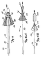
- FIG. 21A illustrates a protection device in accordance with another embodiment of the present invention.
- FIG. 21A illustrates distal protection device 340.
- Device 340 is similar to devices 192 and 206 shown in FIGS. 16A and 16B .
- device. 340 includes hoop-shaped frame 342, filter portion 344, and wire 346.
- Hoop-shaped frame 342 is preferably a self-expanding frame formed of a wire which includes a shape memory alloy.
- hoop-shaped frame 342 is formed of a nitinol wire having a diameter in a range of approximately 0.002 - 0.004 inches.
- Filter portion 344 is preferably formed of a polyurethane material having holes therein such that blood flow can pass through filter 344, but emboli (of a desired size) cannot pass through filter 344 but are retained therein.
- filter material 344 is attached to hoop-shaped frame 342 with a suitable, commercially available adhesive.
- filter 344 has a proximal portion thereof folded over hoop-shaped frame 342, and the filter material is attached itself either with adhesive, by stitching, or by another suitable connection mechanism, in order to secure it about hoop-shaped frame 342. This connection is preferably formed by a suitable adhesive or other suitable connection mechanism.
- the distal end of filter 344 is preferably attached about the outer periphery of wire 346, proximate coil tip 348 on wire 346.
- filter 344 is approximately 15 mm in longitudinal length, and has a diameter at its mouth (defined by hoop-shaped frame 342) of a conventional size (such as 4.0 mm, 4.5 mm, 5 mm, 5.5 mm, or 6 mm). Of course, any other suitable size can be used as well.
- filter 344 is formed of a polyurethane material with the holes laser drilled therein.
- the holes are preferably approximately 100 ⁇ m in diameter.
- filter 344 can also be a microporous membrane, a wire or polymer braid or mesh, or any other suitable configuration.
- Wire 346 is preferably a conventional stainless-steel guidewire having conventional guidewire dimensions.
- wire 346 is a solid core wire having an outer diameter of approximately 0.014 inches and an overall length of up to 300 cm.
- wire 346 has a distal end 350, in a region proximate filter 344, which tapers from an outer diameter at its proximal end which is the same as the outer diameter of the remainder of wire 346, to an outer diameter of approximately 0.055 inches at its distal end.
- guidewire 346 is preferably formed of stainless steel 304.
- guidewires having an outer diameter of approximately 0.018 inches may also be used.
- different dimensions may also be used, such as outer diameters of approximately 0.010 inches to 0.014 inches.
- wire 346 will vary with application. Applications involving neural vasculature will require the use of a smaller guidewire, while other applications will require the use of a larger guidewire.
- wire 346 can be replaced by a hollow guidewire, or hypotube of similar, or other suitable dimensions.
- hoop 346, or filter 344 radiopaque other materials can be used.
- radiopaque loaded powder can be used to form a polyurethane sheath which is fitted over wire 346 or hoop 342, or which is implemented in filter 344.
- hoop 342 and wire 346 can be gold plated in order to increase radiopacity.
- marker bands can be used on wire 346 or filter 344 to increase the radiopacity of the device.
- hoop 342 (and thus filter 344) is preferably collapsed to a radially contracted position which more closely approximates the outer diameter of wire 346. Methods of performing this contraction are described later in the specification.
- wire 346 is manipulated to position hoop 342 and filter 344 distal of a restriction to be treated. Then, the restraining force which is used to restrain hoop 342 in the predeployment, low profile position is removed, and the superelastic properties of nitinol hoop 342 (or the shape memory properties of another shape memory alloy) are utilized in allowing hoop 342 to assume its shape memory position. This causes hoop 342 to define a substantially lumen filling mouth to filter 344 which is positioned distal of the restriction to be treated.
- a suitable dilatation device is then advanced over wire 346 and is used to treat the vascular restriction. Emboli which are carried by blood flow distal of the restriction are captured by filter 344. After the dilatation procedure, filter 344, along with the embolic retained therein, are retrieved from the vasculature. Various retrieval procedures and devices are described later in the specification.
- hoop-shaped frame 342 By allowing hoop-shaped frame 342 to be unattached to wire 346, and only connected to wire 346 through filter 344 (or other super structure used to support filter 344), wire 346 is allowed to substantially float within hoop 342.
- This configuration provides some advantages. For instance, hoop 342 can better follow the vasculature without kinking or prolapsing (i.e., without collapsing upon itself). Thus, certain positioning or repositioning of filter 344 can be accomplished with less difficulty.
- FIG. 21B illustrates a protection device 352 in accordance with another embodiment of the present invention.
- Protection device 352 is similar to protection device 340, and similar items are similarly numbered. However, rather than having simply a hoop-shaped frame 342 to support filter 344, and drive filter 344 into its expanded and deployed position, device 352 includes frame 354 which includes a hoop-shaped portion 356, and a pair of tails 358 and 360.
- Tails 358 and 360 extend proximally from hoop-shaped portion 356 to an attachment region 362.
- tails 358 and 360 are attached to wire 346 at attachment region 362 by soldering, welding, brazing, adhesive, or any other suitable attachment mechanism.
- attachment sleeve 364 formed of a weldable material, is attached at its inner periphery to tails 358 and 360. Sleeve 364 is then attached, using welding or brazing, to wire 346.
- tails 358 and 360 frame 354 is directly connected to wire 346. However, tails 358 and 360 are provided so that the point of attachment of frame 354 to wire 346 is located several millimeters proximal of hoop-shaped portion 356. This provides some additional structural integrity to frame 354, but still allows frame 354 to substantially float about wire 346 in the region of hoop-shaped frame portion 356.
- FIG. 21C illustrates a protection device 366 in accordance with another embodiment of the present invention.
- Protection device 366 is similar to protection devices 340 and 352 shown in FIGS. 21A and 21B , and similar items are similarly numbered.
- device 366 includes hoop-shaped frame 368.
- Frame 368 is similar to frame 342 shown in FIG. 21A .
- hoop 368 does not allow wire 346 to float freely therein. Instead, hoop 368 is directly attached to wire 346 at attachment point 370. This causes hoop-shaped frame 368 and filter 344 to reside eccentrically about wire 346.
- FIGS. 22A-22C illustrate one preferred embodiment for delivering one of devices 340, 352 and 366. For the sake of clarity, only device 352 is illustrated in FIGS. 22A-22C .
- FIG. 22A illustrates delivery device 372.
- delivery device 372 includes proximal hub 374, shaft 376, and distal retaining section 378. Also, in one preferred embodiment, device 372 also includes marker band 380.
- delivery device 372 is similar to a conventional balloon catheter in that proximal hub 374 is a conventional hub, and shaft 376 is a conventional balloon catheter shaft.
- distal retaining section 378 is preferably a conventional angioplasty balloon having an inflated diameter of approximately 1.5 - 2.0 millimeters, but having its distal end cutoff such that the distal end 382 of balloon 378 is open.
- hoop-shaped frame 354 Prior to insertion of device 372 into the vasculature, hoop-shaped frame 354 is retracted into its low profile deployment position and is withdrawn through end 382 into balloon 378. Then, the distal end of balloon 378 is exposed to heat to heat shrink or heat set the distal end of balloon 378 around the radially retracted device 352.
- Device 372, including device 352 is then inserted in the vasculature either through a preplaced guide catheter, along with a guide catheter, or simply without a guide catheter utilizing coil tip 348.
- distal protection device 352 is then removed from within heat collapsed balloon 378.
- the physician simply accomplishes longitudinal movement of wire 346 relative to catheter 376. For instance, the physician may simply hold wire 346 longitudinally in place and withdraw catheter 376 proximally relative to wire 346 by pulling on hub 374. This causes balloon 378 to move proximally relative to device 352, and thereby to expose device 352 to the vasculature.
- FIG. 22B illustrates another preferred embodiment for removing device 352 from within balloon 378.
- syringe 384 which contains fluid, is inserted into coupling 386 in hub 374.
- the physician then introduces pressurized fluid into the lumen of catheter 376.
- the pressurized fluid advances down the lumen of catheter 376 to the distal end where it encounters collapsed balloon 378.
- the pressure exerted on balloon 378 by the pressurized fluid Causes balloon 378 to open radially.
- the physician withdraws catheter 376 relative to device 352 thereby exposing device 352 to the vasculature.
- device 352 assumes its shape memory position in the vasculature, as illustrated in FIG. 22C .
- device 352 substantially forms a lumen-filling basket or filter which allows blood to pass distally therethrough, but which retains or captures embolic material carried by the blood flow.
- the physician then simply removes device 372 from the vasculature, leaving device 352 in place during subsequent procedures.
- shaft 376 includes a predefined slit or score from a region just proximal of marker band 380 to, or through, hub 374. Thus, as the physician removes device 372, it can be peeled away from device 352.
- device 372 can be provided with an aperture in shaft 376 near its distal end.
- the proximal end of wire 346 will thus lie outside of shaft 376.
- Wire 346 can enter shaft 376 through the aperture and extend through the distal end of shaft 376. This also facilitates easier withdrawal of device 372 over wire 346.
- FIGS. 23A-23E illustrate one preferred embodiment for retrieving one of the devices 340, 352 and 366 described in FIGS. 21A-21C .
- FIG. 23A illustrates retrieval device 388.
- Retrieval device 388 is preferably formed of proximal shaft 390, mesh portion 392, and end cap 394. Items 390, 392 and 394 preferably each have lumens therein to define a passageway for receiving wire 346.
- wire 346 may optionally be provided with an positive stop 396 (which can be embodied as a radiopaque marker band).
- Optional stop 396 may also simply be an annular ring attached to wire' 346 proximate to filter 344, or may be any other suitable stop.
- Proximal shaft 390 is preferably simply a polymer or nitinol tube sized and configured to track over wire 346.
- End cap 394 is also preferably formed to track over wire 346, but also contains radiopaque material to serve as a distal marker band for retrieval device 388.
- Mesh 392 is preferably a braid or mesh formed of wire or polymer material having sufficient flexibility that it can be deflected as described below.
- Mesh 392 preferably has a proximal end coupled to proximal shaft 390, by adhesive, welding, or other suitable attachment mechanisms.
- Mesh 392 also preferably includes a distal end connected to end cap 394, also by a suitable connection mechanism.
- device 388 In order to retrieve filter 344, which likely contains embolic material, device 388 is inserted in the low profile position shown in FIG. 23A , over wire 346, to a position proximate filter 344. Then, device 388 is advanced toward filter 344, until end cap 394 abuts positive stop 396, or the hoop-shaped frame 354. Continued advancement of proximal shaft 390 relative to wire 346 causes compression of mesh 392. This results in a radial expansion of an intermediate portion of mesh 392 (between the proximal and distal ends of mesh 392). The radial expansion of mesh portion 392 is illustrated in FIG. 23B .
- the intermediate portion of mesh 392 is configured to bend over on itself such that it is axially displaced toward filter 344, in the direction generally indicated by arrows 398 in FIG. 23C .
- mesh 392 is sized and configured such that, with continued advancement of proximal shaft 390 relative to wire 346, this action continues as shown in FIGS. 23D and 23E until the intermediate portion of mesh 392 encompasses at least the mouth of filter 344.
- the intermediate portion of mesh 392 when driven as described above, engages and contracts the mouth of filter 344 to a lower profile position, such as that shown in FIG. 23E .
- mesh 392 is sized and configured to substantially engulf the entire filter 344.
- device 388, along with device 352 are simply withdrawn from the vasculature.
- devices 388 and 352 are simply withdrawn either into the guide catheter and the guide catheter is removed with those devices, simultaneously, or devices 388 and 352 are removed from the guide catheter prior to removal of the guide catheter.
- devices 388 and 352 are simply removed from the vasculature simultaneously.
- a second actuation tube or wire can also be provided which is attached to end cap 394, and which extends back through the lumen in proximal tube 390 and is longitudinally movable relative to proximal shaft 390.
- the actuation wire or elongate member can be used to pull cap 394 closer to the distal portion of proximal shaft 390 in order to accomplish the action illustrated in FIGS. 23A-23E .
- FIGS. 18A-18D illustrate the mesh portion folded proximally rather than distally.
- FIGS. 24A-24C illustrate another preferred embodiment in accordance with the present invention, for retrieving any of the distal protection devices 340, 352 or 366 shown in FIGS. 21A-21C , For the sake of clarity, only device 352 is illustrated in FIGS. 24A-24C .
- FIG. 24A illustrates retrieval device 400.
- Retrieval device 400 preferably includes retrieval sheath 402, proximal locking device 404, dilator sheath 405, and nose cone 406.
- retrieval sheath 402 is preferably formed of polyether block amide (PEBAX) material having an outer diameter of approximately six French (i.e., approximately 2 mm) and having a shore D hardness of approximately 40.
- retrieval sheath 402 preferably has a wall thickness of approximately 0.004 inches.
- Dilator sheath 405, and nose cone 406, are preferably formed of low density polyethylene, or high density polyethylene.
- Sheath 405 preferably has an outer diameter which is approximately equal to the inner diameter of sheath 402.
- the inner diameter of sheath 405 and nose cone 406 is preferably just large enough to fit over, and track over, wire 346.
- Nose cone 406 preferably has a proximal portion which is either attached to, or formed integrally with, sheath 405.
- the outer diameter of the proximal portion of nose cone 406 is also approximately the same as the outer diameter of sheath 405.
- nose cone 406 also preferably has a distal portion which tapers, or reduces along preferably a smooth curve, to an outer diameter which terminates at the inner diameter of nose cone 406.
- Proximal locking device 404 is preferably any suitable, and commercially available, locking device which can be configured to lock dilator sheath 405 to guidewire 346.
- device 400 is preferably advanced over guidewire 346 to a position shown in FIG. 24B , in which the distal portion of nose cone 406 is closely proximate, or adjacent to, either optional stop 396 or the mouth of filter 344. Then, proximal locking device 404 is actuated to lock dilator sheath 405 to wire 346 so that wire 346 and dilator sheath 405 (as well as nose cone 406) can be moved as a unitary piece.
- wire 346 (and hence dilator sheath 405 and nose cone 406) are withdrawn longitudinally relative to retrieval sheath 402. This causes the mouth of filter 344 to enter within the distal opening in retrieval sheath 402. This results in device 352 being positioned relative to sheath 402 as shown in FIG. 24C .
- wire 346, dilator sheath 405 and nose cone 406 can be withdrawn further into sheath 402 such that the entire filter 344, and wire tip 348, are disposed within the lumen of sheath 402.
- device 352 is configured to be removed from the vasculature. This can be accomplished by either removing dilator sheath 405, nose cone 406 and device 352 as a unitary piece, leaving sheath 402 in place for later removal, or by removing sheath 402 with the remainder of the system, either through a guide catheter or simply through the vasculature, simultaneously. Also, where a guide catheter is used, device 352 and device 400 can be removed through the guide catheter leaving the guide catheter in place, or the guide catheter can be removed simultaneously with the other devices 352 and 400.
- all of the devices according to the present invention can optionally be coated with an antithrombotic material, such as heparin (commercially available under the tradename Duraflow from Baxter), to inhibit clotting.
- an antithrombotic material such as heparin (commercially available under the tradename Duraflow from Baxter), to inhibit clotting.
- the superelastic properties of nitinol are used to form a frame at least in the area of the mouth of the distal protection filter.
- the distal protection device can be deployed, retrieved, and re-deployed any number of times without incurring plastic deformation.
- various deployment and retrieval techniques and systems are provided which address various problems associated with such systems.
Landscapes
- Health & Medical Sciences (AREA)
- Life Sciences & Earth Sciences (AREA)
- General Health & Medical Sciences (AREA)
- Public Health (AREA)
- Engineering & Computer Science (AREA)
- Biomedical Technology (AREA)
- Heart & Thoracic Surgery (AREA)
- Vascular Medicine (AREA)
- Surgery (AREA)
- Animal Behavior & Ethology (AREA)
- Veterinary Medicine (AREA)
- Transplantation (AREA)
- Cardiology (AREA)
- Orthopedic Medicine & Surgery (AREA)
- Nuclear Medicine, Radiotherapy & Molecular Imaging (AREA)
- Oral & Maxillofacial Surgery (AREA)
- Medical Informatics (AREA)
- Molecular Biology (AREA)
- Surgical Instruments (AREA)
- Endoscopes (AREA)
- Media Introduction/Drainage Providing Device (AREA)
Abstract
an elongate retrieval sheath (402) having an outer diameter fitting within the body lumen and having an inner diameter defining a retrieval lumen;
an elongated dilator sheath (405) having an outer diameter approximately equal to the inner diameter of the retrieval sheath (402), the dilator sheath (405) fitting within the retrieval lumen and being longitudinally translatable with respect to the retrieval sheath (402), the dilator sheath (405) having an inner diameter defining a guidewire lumen;
a guidewire (346) disposed within the guidewire lumen and being longitudinally translatable with respect to the dilator sheath (405), the guidewire (346) extending distally beyond a distal end of the dilator sheath (405), the protection device being attached to the guidewire (346) distal to the dilator sheath (405);
a nose cone (406) disposed at a distal end of the dilator sheath (405), the nose cone (406) having an inner diameter sized larger than the inner diameter of the dilator sheath (405), a proximal portion of the nose cone (406) having an outer diameter approximately equal to the outer diameter of the dilator sheath (405), a distal portion of the nose cone (406) having an outer diameter that tapers from a maximum adjacent the proximal portion of the nose cone (406) to a minimum at a distal end of the nose cone (406); and
a proximal locking device (404) configured to lock the dilator sheath (405) to the guidewire (346).
Description
- The present invention deals with an emboli capturing system. More specifically, the present invention deals with an emboli capturing system and method for capturing embolic material in a blood vessel during an atherectomy or thrombectomy procedure.
- Blood vessels can become occluded (blocked) or stenotic (narrowed) in one of a number of ways. For instance, a stenosis may be formed by an atheroma which is typically a harder, calcified substance which forms on the lumen walls of the blood vessel. Also, the stenosis can be formed of a thrombus material which is typically much softer than an atheroma, but can nonetheless cause restricted blood flow in the lumen of the blood vessel. Thrombus formation can be particularly problematic in a saphenous vein graft (SVG).
- Two different procedures have developed to treat a stenotic lesion (stenosis) in vasculature. The first is to deform the stenosis to reduce the restriction within the lumen of the blood vessel. This type of deformation (or dilatation) is typically performed using balloon angioplasty.
- Another method of treating stenotic vasculature is to attempt to completely remove either the entire stenosis, or enough of the stenosis to relieve the restriction in the blood vessel. Removal of the stenotic lesion has been done through the use of radio frequency (RF) signals transmitted via conductors, and through the use of lasers, both of which treatments are meant to ablate (i.e., super heat and vaporize) the stenosis. Removal of the stenosis has also been accomplished using thrombectomy or atherectomy. During thrombectomy and atherectomy, the stenosis is mechanically cut or abraded away from the vessel.
- Certain problems are encountered during thrombectomy and atherectomy. The stenotic debris which is separated from the stenosis is free to flow within the lumen of the vessel. If the debris flows distally, it can occlude distal vasculature and cause significant problems. If it flows proximally, it can enter the circulatory system and form a clot in the neural vasculature, or in the lungs, both of which are highly undesirable.
- Prior attempts to deal with the debris or fragments have included cutting the debris into such small pieces (having a size on the order of a blood cell) that they will not occlude vessels within the vasculature. However, this technique has certain problems. For instance, it is difficult to control the size of the fragments of the stenotic lesion which are severed. Therefore, larger fragments can be severed accidentally. Also, since thrombus is much softer than an atheroma, it tends to break up easier when mechanically engaged by a cutting instrument. Therefore, at the moment that the thrombus is mechanically engaged, there is a danger that it can be dislodged in large fragments which would occlude the vasculature.
- Another attempt to deal with debris severed from a stenosis is to remove the debris, as it is severed, using suction. However, it may be necessary to pull quite a high vacuum in order to remove all of the pieces severed from the stenosis. If a high enough vacuum is not used, all of the severed pieces will not be removed. Further, when a high vacuum is used, this can tend to cause the vasculature to collapse.
- A final technique for dealing with the fragments of the stenosis which are severed during atherectomy is to place a device distal to the stenosis during atherectomy to catch the pieces of the stenosis as they are severed, and to remove those pieces along with the capturing device when the atherectomy procedure is complete. Such capture devices have included expandable filters which are placed distal of the stenosis to capture stenosis fragments. Problems are also associated with this technique. For example, delivery of such devices in a low profile, predeployment configuration can be difficult. Further, some devices include complex and cumbersome actuation mechanisms. Also, retrieving such capture devices, after they have captured emboli, can be difficult as well.
- An emboli capturing system captures emboli in a body lumen. A first elongate member has a proximal end and a distal end. An expandable emboli capturing device is mounted proximate the distal end of the first elongate member, and is movable between a radially expanded position and a radially contracted position. When in the expanded position, the emboli capturing device forms a basket with a proximally opening mouth. A second elongate member has a proximal and a distal end with a lumen extending therebetween. The lumen is sized to slidably receive a portion of the first elongate member. An expandable delivery device is mounted to the distal end of the second elongate member and is movable from a radially retracted position to a radially expanded position. The delivery device has a receiving end configured to receive the emboli capturing device, and retains at least the mouth of the emboli capturing device in a radially retracted position.
- The following aspects are preferred embodiments of the invention.
- 1. An emboli capturing system for capturing emboli in a body lumen, comprising:
- a first elongate member having a proximal end and a distal end;
- an expandable emboli capturing device mounted proximate the distal end of the first elongate member, the emboli capturing device being movable between a radially expanded position and a radially retracted position; the expandable embolic capturing device forming a basket with a proximally opening mouth when in the radially expanded position;
- a second elongate member having a proximal end and a distal end and a lumen extending between the proximal and distal ends,the lumen being sized to slidably receive a portion of the first elongate member therein; and
- an expandable delivery device mounted to the distal end of the second elongate member and being movable from a radially retracted position to a radially expanded position, the delivery device having a receiving end configured to receive the emboli capturing device, the delivery device retaining at least the mouth of the emboli capturing device in the radially retracted position when the delivery device is in the radially retracted position, the emboli capturing device being longitudinally movable out from within the delivery device when the delivery device is in the radially expanded position.
- 2. The emboli capturing system of aspect 1 and further comprising:
- a retrieval device, configured to be longitudinally movable relative to the emboli capturing device in the body lumen and having a receiving end configured to receive at least the mouth of the emboli capturing device when the embolic capturing device is in the radially expanded position.
- 3. The emboli capturing system of aspect 2 wherein the retrieval device comprises the expandable delivery device in the radially expanded position.
- 4. The emboli capturing system of aspect 2 wherein the receiving end of the retrieval device is contractible from a radially expanded position to a radially contracted position to at least partially collapse the emboli capturing device therein.
- 5. The emboli capturing system of
aspect 4 wherein the retrieval device comprises:- a third elongate member having proximal and distal ends and a lumen extending therebetween, the lumen being sized to slidably receive at least a portion of the first elongate member therein, the lumen at the distal end of the third elongate member forming the receiving end and being sized to receive a most radially expanded portion of the emboli capturing device; and
- a fourth elongate member movable within the lumen of the third elongate member, the fourth elongate member having an intermediate region sized to substantially fill the receiving end and a distal tip having an outer diameter less than an outer diameter of the intermediate region.
- 6. The emboli capturing system of aspect 5 wherein the distal tip of the fourth elongate member is configured with an aperture therein sized to track over the first elongate member.
- 7. The embolic capturing system of aspect 6 wherein the fourth elongate member is formed in a substantially conical shape between the distal tip thereof and the intermediate region thereof.
- 8. The emboli capturing system of aspect 2 wherein the retrieval device includes:
- a third elongate member having proximal and distal ends and a lumen extending therebetween, the lumen being sized to slidably receive at least a portion of the first elongate member; and
- a mesh sleeve having a first end coupled to the third elongate member, a second end distal of the first end and an intermediate portion between the first and second ends, the mesh sleeve being configured such that relative longitudinal movement of one of the first and second ends thereof relative to another of the first and second ends thereof drives movement of the mesh portion from a radially retracted position, to a radially expanded position in which the intermediate portion expands radially outward relative to the first and second ends, and to a collapsed position in which the mesh sleeve bends such that the intermediate portion is displaced in a direction toward one of the first and second ends of the mesh sleeve.
- 9. The emboli capturing system of aspect 8 wherein the retrieval device is configured such that sufficient longitudinal movement of the emboli capturing device toward the mesh sleeve causes the emboli capturing device to drive the second end of the mesh sleeve toward the first end of the mesh sleeve.
- 10. The emboli capturing system of aspect 9 wherein the mesh sleeve is sized to encompass at least the mouth of the emboli capturing device as the mesh sleeve moves from the radially expanded position to the collapsed position.
- 11. The emboli capturing system of aspect 2 wherein the retrieval device includes:
- a third elongate member having proximal and distal ends and a lumen extending therebetween, the lumen being sized to slidably receive at least a portion of the first elongate member;
- a fourth elongate member longitudinally movable relative to the third elongate member; and
- a mesh sleeve having a first end coupled to the third elongate member and a second end coupled to the fourth elongate member and an intermediate portion between the first and second ends, the mesh sleeve being configured such that relative longitudinal movement of one of the third and fourth elongate members relative to another of the third and fourth elongate members drives movement of the mesh portion from a radially retracted position, to a radially expanded position in which the intermediate portion expands radially outward relative to the first and second ends, and to a collapsed position in which the mesh sleeve bends such that the intermediate portion is displaced in a direction toward one of the first and second ends of the mesh sleeve.
- 12. The emboli capturing system of aspect 1 wherein the receiving end of the delivery device is defined by a portion of a dilatation balloon.
- 13. The emboli capturing system of aspect 1 wherein the receiving end of the delivery device is thermally shrunk over at least the mouth of the emboli capturing device to retain the emboli capturing device in the radially contracted position during delivery.
- 14. The emboli capturing system of aspect 1 wherein the receiving end of the delivery device is movable from the radially retracted position to the radially expanded position by delivery of pressurized fluid through the lumen in the second elongate member.
- 15. The emboli capturing system of aspect 1 wherein the emboli capturing device is a self-expanding device biased in the radially expanded position.
- 16. The emboli capturing system of aspect 15 wherein the emboli capturing device includes:
- a frame formed of a shape memory alloy; and a filter portion supported by the frame, the filter portion being configured to permit blood flow therethrough and to capture embolic carried by blood flow therethrough.
- 17. The emboli capturing system of
aspect 16 wherein the filter portion has a first end connected to the first elongate member and a second end connected to the frame and wherein the frame comprises:- a loop disposed about the first elongate member to define the mouth of the emboli capturing device.
- 18. The emboli capturing system of aspect 17 wherein the loop is directly connected to the first elongate member.
- 19. The emboli capturing system of aspect 17 wherein the shape memory alloy comprises an alloy having superelastic properties.
- 20. The emboli capturing system of aspect 19 wherein the shape memory alloy includes nitinol.
- 21. The embolic capturing system of
aspect 20 wherein the emboli capturing device is substantially conical in shape. - 22. The emboli capturing system of aspect 21 wherein the filter portion comprises a polyurethane member having a plurality of holes therein.
- 23. The embolic capturing system of aspect 1 wherein the first elongate member comprises a guidewire.
- 24. A method of capturing emboli carried by flow of fluid through a body lumen, the method comprising:
- providing a first elongate member having a proximal end and a distal end;
- providing an expandable emboli capturing device mounted proximate the distal end of the first elongate member, the emboli capturing device being movable between a radially expanded position and a radially retracted position, the expandable emboli capturing device defining a proximally opening mouth when in the radially expanded position;
- providing a second elongate member having a proximal end and a distal end and a lumen extending between the proximal and distal ends, the lumen being sized to slidably receive a portion of the first elongate member therein;
- providing an expandable delivery device mounted to the distal end of the second elongate member and being movable from a radially retracted position to a radially expanded position, the delivery device having a receiving end configured to receive the emboli capturing device, the delivery device retaining at least the mouth of the emboli capturing device in the radially retracted position when the delivery device is in the radially retracted position;
- inserting the expandable delivery device into the lumen with the mouth of the emboli capturing device retained in the radially retracted position within the delivery device;
- expanding the expandable delivery device into the radially expanded position; and longitudinally moving the delivery device relative to the emboli capturing device to remove the emboli capturing device from within the delivery device.
- 25. The method of
aspect 24 and further comprising:- providing a retrieval device, configured to be longitudinally movable relative to the emboli capturing device in the body lumen and having a receiving end configured to receive at least the mouth of the emboli capturing device when the emboli capturing device is in the radially expanded position; and
- longitudinally moving the delivery device relative to the emboli capturing device such that at least the mouth of the emboli capturing device is in the receiving end of the retrieval device.
- 26. The method of aspect 25 wherein the receiving end of the retrieval device is contractible from a radially expanded position to a radially contracted position, and further comprising:
- contracting the receiving end of the retrieval device to at least partially collapse the emboli capturing device therein.
- 27. The method of
aspect 26 wherein providing a retrieval device comprises:- providing a third elongate member having proximal and distal ends and a lumen extending therebetween, the lumen being sized to slidably receive at least a portion of the first elongate member therein, the lumen at the distal end of the third elongate member forming the receiving end and being sized to receive a most radially expanded portion of the emboli capturing device;
- providing a fourth elongate member movable within the lumen of the third elongate member, the fourth elongate member having an intermediate region sized to substantially fill the receiving end and a distal tip having an outer diameter less than an outer diameter of the intermediate region;
- advancing the third and fourth elongate members over the first elongate member, with the intermediate region of the fourth elongate member positioned within the third elongate member to fill the receiving end thereof, to a point proximate the emboli capturing device;
- withdrawing the distal tip of the fourth elongate member within the lumen of the third elongate member; and
- positioning at least the mouth of the emboli capturing device within the receiving end of the retrieval device.
- 28. The method of aspect 27 and further comprising:
- withdrawing the first, third, and fourth elongate members from the body lumen.
- 29. The method of aspect 25 wherein providing the retrieval device includes:
- providing a third elongate member having proximal and distal ends and a lumen extending therebetween, the lumen being sized to slidably receive at least a portion of the first elongate member;
- providing a mesh sleeve having a first end coupled to the third elongate member, a second end distal of the first end and an intermediate portion between the first and second ends, the mesh sleeve being configured such that relative longitudinal movement of one of the first and second ends thereof relative to another of the first and second ends thereof drives movement of the mesh portion from a radially retracted position, to a radially expanded position in which the intermediate portion expands radially outward relative to the first and second ends, and to a collapsed position in which the mesh sleeve bends such that the intermediate portion is displaced in a direction toward one of the first and second ends of the mesh sleeve;
- advancing the third elongate member into the body lumen over the first elongate member to a point proximate the mouth of the emboli capturing device; and
- accomplishing relative longitudinal movement of the emboli capturing device and the mesh sleeve toward one another, driving the second end of the mesh sleeve toward the first end of the mesh sleeve such that the mesh sleeve encompasses at least the mouth of the emboli capturing device as the mesh sleeve moves from the radially expanded position to the collapsed position.
- 30. The method of
aspect 24 wherein expanding comprises:- delivering pressurized fluid through the lumen in the second elongate member.
-
-
FIG. 1 shows a distal protection device of the present invention in a deployed position. -
FIG. 2 shows the distal protection device shown inFIG. 1 in a collapsed position. -
FIG. 3 shows an end view of a portion of the distal protection device shown inFIGS. 1 and 2 . -
FIG. 4 shows a cross-sectional view of a portion of the distal protection device shown inFIGS. 1-3 in the deployed position. -
FIG. 5 shows a second embodiment of the distal protection device according to the present invention in a deployed position. -
FIG. 6 shows an end view of the distal protection device shown inFIG. 5 . -
FIG. 7 shows a cross-sectional view of the distal protection device shown inFIGS. 5 and 6 in the collapsed position. -
FIG. 8 shows a third embodiment of a distal protection device according to the present invention in a deployed position. -
FIG. 9 is a side sectional view of an alternate embodiment illustrating how the expandable members of the present invention are attached to a guidewire. -
FIG. 10 is a sectional view taken along section lines 10-10 inFIG. 9 . -
FIGS. 11A and 11B show a fourth and fifth embodiment, respectively, of a distal protection device according to the present invention in a deployed position. -
FIG. 12 illustrates the operation of a distal protection device in accordance with the present invention. -
FIGS. 13A-17B show additional embodiments of distal protection devices which expand and collapse based on movement of a mechanical actuator. -
FIGS. 18A-18D illustrate an additional embodiment of a distal protection device which is deployed and collapsed using a rolling flap configuration. -
FIG. 19 illustrates another embodiment in accordance with the present invention in which the protection device is deployed using fluid pressure and a movable collar. -
FIGS. 20A and 20B illustrate another aspect of the present invention in which two longitudinally movable members used to deploy the distal protection device are disconnectably locked to one another. -
FIGS. 21A-21C illustrate another embodiment in accordance with the present invention in which the protection device is formed with a shape memory alloy frame and an attached filter or mesh mounted to the frame. -
FIGS. 22A-22C illustrate another embodiment in accordance with the present invention in which the distal protection devices shown inFIGS. 21A-21C are delivered and deployed. -
FIGS. 23A-23E illustrate another embodiment in accordance with the present invention in which the distal protection devices shown inFIGS. 21A-21C are retrieved. -
FIGS. 24A-24C illustrate another embodiment in accordance with the present invention in which the distal protection devices shown inFIGS. 21A-21C are retrieved. -
FIG. 1 illustratesprotection device 10 in a deployed position within the lumen of ablood vessel 12.Protection device 10 preferably includes hollow guidewire 14 (or a hypotube having the same general dimensions as a guidewire) having acoil tip 16, and a capturingassembly 18. Capturingassembly 18, in the embodiment shown inFIG. 1 , includes an inflatable andexpandable member 20 andmesh 22. - An interior of
expandable member 20 is preferably coupled for fluid communication with an inner lumen ofguidewire 14 at a distal region ofguidewire 14. When deployed,inflatable member 20 inflates and expands to the position shown inFIG. 1 such that capturingassembly 18 has an outer periphery which approximates the inner periphery oflumen 12. -
Mesh 22 is preferably formed of woven or braided fibers or wires, or a microporous membrane, or other suitable filtering or netting-type material. In one preferred embodiment,mesh 22 is a microporous membrane having holes therein with a diameter of approximately 100 µm.Mesh 22 can be disposed relative toinflatable member 20 in a number of different ways. For example, mesh 22 can be formed of a single generally cone-shaped piece which is secured to the outer or inner periphery ofinflatable member 20. Alternatively, mesh 22 can be formed as a spiral strip which is secured about the outer or inner periphery ofinflatable member 20 filling the gaps between the loops ofinflatable member 20. Alternatively, mesh 22 can be formed of a number of discrete pieces which are assembled ontoinflatable member 20. -
Hollow guidewire 14 preferably has avalve 24 coupled in a proximal portion thereof. During operation, a syringe is preferably connected to the proximal end ofguidewire 14, which preferably includes a fluid hypotube. The syringe is used to pressurize the fluid such that fluid is introduced through the lumen ofhollow guidewire 14, throughvalve 24, and intoinflatable member 20. Upon being inflated,inflatable member 20 expands radially outwardly from the outer surface ofguidewire 14 and carriesmesh 22 into the deployed position shown inFIG. 1 . In this way, capturing assembly, or filter assembly, 18 is deployed distally ofstenosis 26 so thatstenosis 26 can be severed and fragmented, and so the fragments fromstenosis 26 are carried by blood flow (indicated by arrow 28) into the basket or chamber formed by the deployedfilter assembly 18.Filter assembly 18 is then collapsed and removed fromvessel 12 with the fragments ofstenosis 26 contained therein. -
FIG. 2 illustratesprotection device 10 withfilter assembly 18 in the collapsed position. Similar items to those shown inFIG. 1 are similarly numbered.FIG. 2 illustrates thatmesh 22 is easily collapsible withinflatable member 20. In order to collapsefilter assembly 18, fluid is preferably removed frominflatable member 20 through the lumen ofhollow guidewire 14 and through two-way valve 24. This can be done using the syringe to pull a vacuum, or using any other type of suitable fluid removal system. -
Inflatable member 20 is preferably formed of a material having some shape memory. Thus, wheninflatable member 20 is collapsed, it collapses to approximate the outer diameter ofhollow guidewire 14. In one preferred embodiment,inflatable member 20 is formed of a resilient, shape memory material such that it is inflated by introducing fluid under pressure through the lumen inhollow guidewires 14 intoinflatable member 20. When pressure is released from the lumen inhollow guidewire 14,inflatable member 20 is allowed to force fluid out from the interior thereof through two-way valve 24 and to resume its initial collapsed position. Again, this results infilter assembly 18 assuming its collapsed position illustrated inFIG. 2 . -
FIG. 3 illustrates a view taken from the distal end ofdevice 10 withmesh 22 removed for clarity.FIG. 3 shows that, wheninflatable member 20 is deployed outwardly, mesh 22 (when deployed between the loops of inflatable member 20) forms a substantially lumen-filling filter which allows blood to flow therethrough, but which provides a mechanism for receiving and retaining stenosis fragments carried intomesh 22 by blood flow through the vessel. -
FIG. 3 also shows thatinflatable member 20 preferably has aproximal end portion 29 which is connected to the outer periphery ofguidewire 14. Althoughend 29 need not be connected to guidewire 14, it is preferably connected using adhesive or any other suitable connection mechanism. By fixedly connectingproximal end portion 29 to guidewire 14, this increases the stability of thefilter assembly 18 upon deployment. -
FIG. 4 is a cross-sectional view of a portion ofprotection device 10.FIG. 4 showsprotection device 10 withfilter assembly 18 in the expanded or deployed position.FIG. 4 also better illustrates thatguidewire 14 is hollow and has alongitudinal lumen 30 extending therethrough.Longitudinal lumen 30 is connected in fluid communication with an interior ofinflatable member 20 through aperture 32 which is provided in the wall ofguidewire 14.FIG. 4 also shows that, in one preferred embodiment, acore wire 34 extends throughlumen 30 from a proximal end thereof where it is preferably brazed to a portion of a hypotube which may be connected to the proximal portion ofguidewire 14. Thecore wire 34 extends to the distal end ofguidewire 14 where it is connected tocoil tip 16. In one preferred embodiment,coil tip 16 is brazed or otherwise welded or suitably connected to the distal portion ofcore wire 34. -
FIG. 4 further shows that, in the preferred embodiment,inflatable member 20 inflates to a generally helical, conical shape to form a basket opening toward the proximal end ofguidewire 14.FIG. 4 further illustrates, in the preferred embodiment,mesh 22 has adistal portion 38 which is connected to the exterior surface ofguidewire 14, at a distal region thereof, through adhesive 36 or any other suitable connection mechanism. -
FIG. 5 illustrates a second embodiment of adistal protection device 40 in accordance with the present invention.Device 40 includeshollow guidewire 42,filter assembly 44 andcoil tip 16.Filter assembly 44 includes a plurality ofinflatable struts 46 and mesh 47. Eachstrut 46 has adistal end 48 andproximal end 50. Inflatable struts 46 also have an interior which is coupled in fluid communication, throughdistal end 48 thereof, with the lumen inhollow guidewire 42.Struts 46 are preferably configured such that, upon being inflated, the proximal ends 50 deploy radially outwardly away from the outer surface ofhollow guidewire 42 to assume a dimension which approximates the inner dimension oflumen 58 in which they are inserted. - Mesh 47, as with
mesh 22 shown inFIG. 1 , is deployed either on the outer or inner surface ofinflatable struts 46, such that, when theinflatable struts 46 are deployed radially outwardly, mesh 47 forms a generally conical basket opening toward the proximal end ofhollow guidewire 42. As with the embodiment shown inFIG. 1 , mesh 47 can be applied to either the outer or the inner surface ofstruts 46. It can be applied tostruts 46 as one unitary conical piece which is adhered about distal ends 48 ofstruts 46 using adhesive (or about the distal end ofguidewire 42 using adhesive) and secured to the surface of thestruts 46 also using adhesive. Alternatively, mesh 47 can be applied tostruts 46 in a plurality of pieces which are individually or simultaneously secured to, and extend between, struts 46. -
FIG. 6 is an end view ofdistal protection device 40 shown inFIG. 5 taken from the distal end ofdistal protection device 40. When struts 46 are deployed outwardly, mesh 47 forms a substantially lumen-filling filter which allows blood to flow therethrough, but which provides a mechanism for receiving and retaining stenosis fragments fromstenosis 56 carried into mesh 47 by blood flow through the vessel. -
FIG. 7 is a cross-sectional view of a portion ofdistal protection device 40 shown inFIGS. 5 and 6. FIG. 7 shows filter assembly 44 in the collapsed position in which it approximates the outer diameter ofguidewire 42.FIG. 7 also shows that, in the preferred embodiment, the distal ends 48 ofstruts 46 are in fluid communication with aninner lumen 52 inhollow guidewire 42 throughapertures 54 in the wall ofguidewire 42. -
FIG. 8 illustrates another embodiment of adistal protection device 60 in accordance with the present invention.Distal protection device 60 is similar to those shown in other figures, and similar items are similarly numbered. However,distal protection device 60 includeshollow guidewire 63 which has a lumen in fluid communication with an interior of a pair ofinflatable struts 62. Inflatable struts 62 have aninner surface 64 which is generally concave, or hemispherical, or otherwise appropriately shaped such that it extends about a portion of the outer surface ofhollow guidewire 63.Mesh portions 66 extend between theinflatable struts 62 so thatinflatable struts 62 andmesh portions 66, when deployed outwardly as shown inFIG. 8 , form a basket shape which opens toward the proximal end ofhollow guidewire 63. -
FIG. 9 illustrates another system for attaching inflatable struts to a hollow guidewire for adistal protection device 70 in accordance with the present invention.Distal protection device 70 is similar to the distal protection devices shown in the previous figures in that a plurality ofinflatable struts 72 are provided and preferably have a mesh portion extending therebetween. For the sake of clarity, the mesh portion is eliminated fromFIG. 9 . However, it will be understood that, when deployed,distal protection device 70 forms a generally basket-shaped filter assembly which opens toward the proximal end ofhollow guidewire 74. - In the embodiment shown in
FIG. 9 ,hollow guidewire 74 has adistal end 75 which is open. Anendcap 76 is disposed about thedistal end 75 ofhollow guidewire 74 and defines an internal chamber orpassageway 78.Endcap 76 has aproximal end 80 which has openings therein for receiving the ends ofinflatable struts 72. Thus, in order to inflateinflatable struts 72, the operator pressurizes fluid within the lumen ofhollow guidewire 74 forcing fluid out throughdistal end 75 ofhollow guidewire 74, throughpassageway 78, and intoinflatable struts 72. In order to collapsedistal protection device 70, the operator draws a vacuum which pulls the fluid back out ofinflatable struts 72, throughpassageway 78 and, if necessary, into the lumen ofhollow guidewire 74. -
FIG. 10 is an end view ofendcap 76 taken along lines 10-10 inFIG. 9. FIG. 10 shows thatproximal end 80 ofendcap 76 preferably includes a first generallycentral aperture 82 for receiving the distal end ofhollow guidewire 74.Aperture 82 is sized just larger than, or approximating, the outer diameter ofhollow guidewire 74 such that it fits snugly over thedistal end 75 ofhollow guidewire 74.Endcap 76 is then fixedly connected to thedistal end 75 ofhollow guidewire 74 through a friction fit, a suitable adhesive, welding, brazing, or another suitable connection technique. -
FIG. 10 also shows thatproximal end 80 ofendcap 76 includes a plurality ofapertures 84 which are spaced from one another aboutend 80.Apertures 84 are sized to receive open ends ofinflatable struts 72. In the preferred embodiment,inflatable struts 72 are secured withinapertures 84 using a suitable adhesive, or another suitable connection technique. Also, in the preferred embodiment,spring tip 16 is embedded in, or otherwise suitably connected to,endcap 76. -
FIGS. 11A and 11B show two other preferred embodiments of a distal protection device in accordance with the present invention.FIG. 11A showsdistal protection device 90 which includeshollow guidewire 92 having a lumen running therethrough,inflatable member 94 andmesh portion 96.FIG. 11A shows thatinflatable member 94, when inflated, forms a ring about the outer surface ofhollow guidewire 92. The ring has aninner periphery 98 which is spaced from the outer surface ofhollow guidewire 92 substantially about the entire radial periphery ofhollow guidewire 92.Mesh portion 96 extends between the outer surface ofhollow guide 92 and theinner periphery 98 ofinflatable member 94. Thus, a substantially disc-shaped filter assembly is provided upon deployment ofdistal protection device 90. As with the other embodiments, deployment ofdistal protection device 90 is accomplished by providing fluid through the inner lumen ofhollow guidewire 92 into an interior ofinflatable member 94 which is in fluid communication with the inner lumen ofhollow guidewire 92. - In one preferred embodiment, end 100 of
inflatable member 94 is coupled to acoupling portion 102 ofinflatable member 94 such that stability is added toinflatable member 94, when it is inflated. -
FIG. 11B illustrates anotherdistal protection device 104 which includes ahollow guidewire 106 and an inflatable member 108.Device 104 is similar todistal protection device 90 except that, rather than having only a single inflatable ring upon deployment ofdistal protection device 104, a plurality of generally equal-diameter rings are formed into a helix shape. In the preferred embodiment,distal protection device 104 includes amesh sleeve 110 which extends about the outer or inner surface of the helix formed by inflatable member 108. In one embodiment,mesh sleeve 110 is connected to the outer surface ofhollow guidewire 106 in aregion 112 proximate, but distal of, inflatable member 108. In another preferred embodiment, the proximal end ofmesh sleeve 110 is connected to the outer perimeter of inflatable member 108. Thus,distal protection device 104 forms a generally basket-shaped filter assembly which opens toward a proximal end ofguidewire 106. - As with the other embodiments, both
distal protection device 90 shown inFIG. 11A anddistal protection device 104 shown inFIG. 11B are preferably collapsible. Therefore, when collapsed, thedistal protection devices hollow guidewires distal protection devices hollow guidewires -
FIG. 12 illustrates the use of a distal protection device in accordance with the present invention. For the sake of clarity, the present description proceeds with respect todistal protection device 10 only.Device 10 is shown filtering stenosis fragments from the blood flowing through the lumen ofvessel 12.FIG. 12 also shows adilatation device 120 which can be any suitable dilatation device for dilating, cutting, fragmenting, or abrading, portions ofstenosis 26. In the preferred embodiment,device 120 is used in an over-the-wire fashion overhollow guidewire 14. Thus,filter assembly 18 is first advanced (using guidewire 14) distal ofstenosis 26. Then, filterassembly 18 is deployed outwardly to the expanded position.Dilatation device 120 is then advanced overguidewire 14 tostenosis 26 and is used to fragment or abradestenosis 26. The fragments are received within the basket offilter assembly 18.Filter assembly 18 is then collapsed, and filterassembly 18 anddilatation device 120 are removed fromvessel 12. Alternatively,dilatation device 120 can be removed first and filterassembly 18 is then removed along withguidewire 14. - It should be noted that the stenosis removal device (or atherectomy catheter) 120 used to
fragment stenosis 26 can be advanced overguidewire 14. Therefore, the device according to the present invention is dual functioning in that it captures emboli and serves as a guidewire. The present invention does not require adding an additional device to the procedure. Instead, the present invention simply replaces a conventional guidewire with a multi-functional device. -
FIGS. 13A-17B illustrate embodiments of various distal protection devices wherein deployment and contraction of the distal protection device is accomplished through a mechanical push/pull arrangement. -
FIGS. 13A and 13B illustrate adistal protection device 122.FIG. 13A showsdevice 122 in an undeployed position andFIG. 13B showsdevice 122 in a deployed position.Distal protection device 122 includes a slottedNitinol tube 124 which has alumen 126 extending therethrough.Tube 124 has a plurality ofslots 128 at a distal region thereof. The distal portion ofslots 128 are covered bymesh 130 which, in the preferred embodiment, is a flexible microporous membrane.Device 122 also preferably includes amandrel 132 which extends through theinner lumen 126 oftube 124 and is attached to the distal end oftube 124. In the preferred embodiment,mandrel 132 is attached to the distal end oftube 124 by an appropriate adhesive, brazing, welding, or another suitable connection technique.Tube 124 also has, on its inner periphery in a proximal region thereof, a plurality of lockingprotrusions 134.Lock protrusions 134 are preferably arranged about a proximalexpandable region 136 disposed onmandrel 132. - In order to deploy
device 122 into the deployed position shown inFIG. 13B , the operator preferably first advancestube 124 distally of the lesion to be fragmented. In the preferred embodiment,tube 124 has a size on the order of a guidewire, such as a 0.014 inch outer diameter. Therefore, it easily advances beyond the stenosis to be fragmented. The operator then pushes on the proximal region oftube 124 and pulls on the proximal end ofmandrel 132. This causes two things to happen. First, this causes the struts formed byslots 128 to expand radially outwardly, and carry with them,microporous membrane 130. Thus,microporous membrane 130 forms a generally basket-shaped filter assembly which opens toward the proximal end oftube 124. In addition, proximalexpandable member 136 expands and engagesprotrusions 134. This locksdevice 122 in the deployed and expanded position. In order to move thedevice 122 to the collapsed position, the physician simply pushes onmandrel 132 and pulls on the proximal end oftube 124. This causesdevice 122 to return to the undeployed position shown inFIG. 13A . - It should be noted that
device 122 can optionally be provided with a stainless steel proximal hypotube attachment. Also, the struts defined byslots 128 can be expanded and retracted using a fluid coupling instead of a mandrel. In other words, the proximal end oftube 124 can be coupled to a pressurizable fluid source. By makingslots 128 very thin, and pressurizing the fluid, the struts expand outwardly. Further, by pulling vacuum on the pressurizable fluid, the struts collapse. -
FIG. 14A illustratesdistal protection device 140 which is similar to that shown inFIGS. 13A and 13B , except that thestruts 142 are formed of a metal or polymer material and are completely covered bymesh 144.Mesh 144 includes two mesh portions, 146 and 148.Mesh portion 146 is proximal ofmesh portion 148 ondevice 140 and is a relatively loose mesh which will allow stenosis fragments to pass therethrough. By contrast,mesh 148 is a fairly tight mesh, or a microporous membrane, (or simplyloose mesh portion 146 with a microporous membrane or other suitable filter material bonded or cast or otherwise disposed thereover) which does not allow the fragments to pass therethrough and therefore captures and retains the fragments therein. The mesh portions can provide a memory set which, in the relaxed position, is either deployed or collapsed. -
FIG. 14B illustrates adevice 150 which is similar todevice 140 shown inFIG. 14A , exceptstruts 142 are eliminated and the two mesh portions 146' and 148' are simply joined together at aregion 152. Also, the two mesh portions 146' and 148' are not two different discrete mesh portions but are formed of the same braided mesh material wherein the braid simply has a different pitch. The wider pitch in region 146' provides a looser mesh, whereas the narrower pitch in region 148' provides a tighter mesh that traps the embolic material. -
FIG. 14C illustrates adistal protection device 160 which is similar to that shown inFIG. 14A . However, rather than simply providing a slotted tube,distal protection device 160 includes a plurality ofstruts 162 on a proximal region thereof and a plurality ofstruts 164 on the distal region thereof.Struts 162 are spaced further apart thanstruts 164 about the periphery ofprotection device 160. Therefore, struts 162 defineopenings 166 which are larger than the openings 168 defined bystruts 164 and allow stenosis fragments to pass therethrough. Also, struts 164 have secured to the interior surface thereof a filter ormesh portion 170. When deployed,filter portion 170 forms a substantially basket-shaped filter device opening toward the proximal region oftube 172. -
FIG. 15 illustrates the operation of anotherdistal protection device 176.Distal protection device 176 includes a tube 178 and a push/pull wire 180. Tube 178 has, at the distal end thereof, afilter assembly 182.Filter assembly 182 includes a plurality of preferably metal struts 184 which have a microporous membrane, or othersuitable mesh 186 disposed thereon. Tube 178 also preferably includesend cap 188 and umbrella-like expansion structure 190 disposed at a distal region thereof.Expansion structure 190 is connected to the distal region of tube 178 and to metal struts 184 such that, when push/pull wire 180 is pulled relative to tube 178,expansion member 190 exerts a radial, outwardly directed force onstruts 184 causing them to expand radially outwardly relative to the outer surface of tube 178. This causes microporous membrane or mesh 186 to be deployed in a manner opening toward the proximal end of tube 178 to catch embolic material.Struts 184 can also be formed of an appropriate polymer material. -
FIGS. 16A and 16B illustrate a protection device in accordance with another embodiment of the present invention.FIG. 16A illustratesdistal protection device 192.Device 192 includesguidewire 194,actuator wire 196, and filterassembly 198.Filter assembly 198 includes anexpandable ring 200, such as an expandable polymer or metal or other elastic material, which has attached thereto mesh 202.Mesh 202 is also attached to guidewire 194 distally ofring 200.Actuator wire 196 is attached to sleeve orsheath 204 which is positioned to fit about the outer periphery ofexpandable ring 200, whenexpandable ring 200 is in the collapsed position. - Thus, when
sheath 204 is moved distally ofexpandable ring 200,expandable ring 200 has shape memory which causes it to expand into the position shown inFIG. 16A . Alternatively, whensheath 204 is pulled proximally by pullingactuator wire 196 relative to guidewire 194,sheath 204 collapsesring 200 and holdsring 200 in the collapsed position withinsheath 204. Manipulatingwires device 192 to move from the deployed position to the collapsed position, and vice versa. -
FIG. 16B is similar todevice 192 except that, instead of having anexpandable ring 200 connected at one point to wire 194,distal protection device 206 includesexpandable member 208 which is formed of an elastic coil section ofwire 194. Thus,elastic coil section 208 has a shape memory which causes it to expand into the generally helical, conical shape shown inFIG. 16B . However, whensheath 204 is pulled proximally relative toexpandable member 208, this causessheath 204 to capture and retainexpandable member 208 in a collapsed position. Whensheath 204 is again moved distally ofexpandable member 208,expandable member 208 returns to its expanded position shown inFIG. 16B carrying with it mesh 210 into a deployed position. In the preferred embodiment,sheath 204 is formed of a suitable polymer material andexpandable member 208 andexpandable ring 200 are preferably formed of Nitinol. -
FIGS. 17A and 17B illustrate the operation of anotherdistal protection device 212.Protection device 212 includesguidewire 214 andfilter assembly 216. In the preferred embodiment,filter assembly 216 includes awire braid portion 218 which extends from a distal region ofguidewire 214 proximally thereof.Braid portion 218 is formed of braided filaments or fibers which have a shape memory causing them to form a deployed, basket-shaped filter, such as that shown inFIG. 17A , in the unbiased position.Braided portion 218 terminates at its proximal end in a plurality ofeyelets 220. One ormore cinch wires 222 are preferably threaded througheyelets 220. By pushing onguidewire 214 and pulling oncinch wires 222, the operator is able to cinch closed, and pull proximally, the proximal portion ofmesh 218. This causesmesh 218 to collapse tightly about the outer surface ofwire 214. - Therefore, during operation, the operator holds
mesh 218 in the collapsed position and insertsprotection device 212 distally of the desired stenosis. The operator then allowscinch wire 222 to move distally relative toguidewire 214. This allowsmesh 218 to open to the deployed position shown inFIG. 17A which has an outer diameter that approximates the inner diameter of the lumen within which it is disposed.Filter assembly 216 is then disposed to capture embolic material from blood flowing therethrough. Once the embolic material is captured, the operator again movescinch wire 222 proximally relative to guidewire 214 to collapsefilter assembly 216 and capture and retain the embolic material infilter assembly 216. Thedevice 212 is then removed. -
FIG. 17B showsdistal protection device 212 except that in the embodiment shown inFIG. 17B ,protection device 212 is not disposed distally of the stenosis, but rather proximally. This results, for example, in an application where the blood flow is proximal of the stenosis rather than distal. Further, in the embodiment shown inFIG. 17B , guidewire 214 is preferably hollow and thecinch wire 222 extends through the lumen therein. By pushing onguidewire 214, a force is exerted onmesh 218 in the distal direction. This causescinch wire 222 to tightly close the distal opening infilter assembly 216 and to collapsemesh portion 218. By contrast, by allowingcinch wire 222 to move distal relative tohollow guidewire 214,mesh portion 218 expands and filterassembly 216 is deployed as shown inFIG. 17B . -
FIGS. 18A and 18B illustrate adistal protection device 250 in accordance with another aspect of the present invention.Device 250 includesinner wire 252 andouter tube 254. In the preferred embodiment,inner wire 252 is a core wire andouter tube 254 has a lumen 256 therein large enough to accommodate longitudinal movement ofinner wire 252 therein. Also, in the preferred embodiment,inner wire 252 has, coupled to itsdistal end 258, aspring tip 260. -
Device 250 includes expandable mesh orbraid portion 262.Expandable portion 262 has a proximal end 264 which is attached to thedistal end 266 oftube 254. Also,expandable member 262 has adistal end 268 which is attached to thedistal end 258 ofinner wire 252. -
Expandable member 262 is preferably a mesh or braided material which is coated with polyurethane. In one preferred embodiment, a distal portion ofexpandable member 262 has a tighter mesh than a proximal portion thereof, or has a microporous membrane or other suitable filtering mechanism disposed thereover. In another preferred embodiment,expandable member 262 is simply formed of a tighter mesh or braided material which, itself, forms the filter.FIG. 18A illustratesdevice 250 in a collapsed, or insertion position wherein the outer diameter ofmesh portion 262 closely approximates the outer diameters of eitherinner wire 252 orouter tube 254. -
FIG. 18B illustratesdevice 250 in the deployed position in whichexpandable member 262 is radially expanded relative to the collapsed position shown inFIG. 18A . In order to deploydevice 250, theouter tube 254 is moved distally with respect toinner wire 252 such that the distal ends 266 and 258 ofwires ends expandable member 262 to buckle and fold radially outwardly. Thus, the outer diameter ofexpandable member 262 in the deployed position shown inFIG. 18B closely approximates the inner diameter of a vessel within which it is deployed. -
FIG. 18C illustratesdevice 250 in a partially collapsed position. InFIG. 18C , thedistal end 266 ofouter tube 254 and thedistal end 258 ofinner wire 252 are moved even closer together than they are as shown inFIG. 18B . This causesexpandable mesh portion 262 to fold over itself and form a rolling, proximally directedflap 270. As longitudinal movement ofinner wire 252 proximally with respect toouter tube 254 continues,mesh portion 262 continues to fold over itself such that the rollingflap portion 270 has an outer radial diameter which continues to decrease. In other words,expandable mesh portion 262 continues to fold over itself and to collapse over the outer periphery ofouter tube 254. -
FIG. 18D illustratesdevice 250 in a fully collapsed position in which it retains embolic captured therein. InFIG. 18D , thedistal end 266 ofouter tube 254 has been advanced as far distally as it can relative to thedistal end 258 ofinner wire 252. This causesexpandable mesh portion 262 to fold all the way over on itself such that it lies against, and closely approximates the outer diameter of,outer tube 254.Device 250 thus captures any emboli filtered from the vessel within which it was deployed, and can be removed while retaining that embolic material. -
FIG. 19 illustratesdevice 280 which depicts a further aspect in accordance with the present invention.Device 280 includes outer tube 282,core wire 284,transition tube 286,movable plunger 288,expandable member 290, fixedcollar 292 andbias member 294. - In the preferred embodiment, tube 282 comprises a proximal hypotube which is coupled to a plunger that selectively provides fluid under pressure through an
inflation lumen 296.Inner wire 284 is preferably a tapered core wire which terminates at its distal end in aspring coil tip 298 and which is coupled at itsproximal end 300 to transitiontube 286.Transition tube 286 is preferably an outer polymer sleeve either over hypotube 282, or simply disposed by itself and coupled to a hypotube 282.Transition tube 286 is capable of withstanding the inflation pressure provided by the fluid delivered through theinflation lumen 296. -
Movable collar 288 is preferably slidably engageable with the interior surface oftransition tube 286 and with the exterior surface ofcore wire 284, and is longitudinally movable relative thereto.Slidable collar 288 has, attached at its distal end,bias spring 294 which is preferably coiled aboutcore wire 284 and extends to fixedcollar 292.Fixed collar 292 is preferably fixedly attached to the exterior surface of a distal portion ofcore wire 284. -
Expandable member 290 is preferably formed, at a proximal portion thereof, of either discrete struts, or another suitable frame (such as a loose mesh) which allows blood and embolic material to flow therethrough. Theproximal end 302 ofexpandable member 290 is coupled to a distal region ofmovable collar 288. The distal portion ofexpandable member 290 is preferably formed of a filtering material which is suitable for allowing blood flow therethrough, but which will capture embolic material being carried by the blood. - In one preferred embodiment,
spring 294 is biased to forcecollars spring 294 urgescollars collar 288 retracts withintransition tube 286 pullingexpandable member 290 into a collapsed position aboutcore wire 284. However, in order to deploycollapsible member 290 as shown inFIG. 19 , the operator preferably actuates a plunger (not shown) which delivers pressurized fluid throughlumen 296. The pressurized fluid enterstransition tube 286 and travels about the outer periphery ofinner core wire 284, thus forcingmovable collar 288 to move distally alongcore wire 284. This overcomes the spring force exerted byspring 294 thus causingcollars expandable member 290 to buckle and expand outwardly to the deployed position shown inFIG. 19 . -
Expandable member 290 is collapsed by releasing the pressure applied through lumen 296 (i.e., by causing the plunger to move proximally). This allowsspring 294 to again urgecollars expandable member 290. In an alternative embodiment, the frame supportingexpandable member 290 is imparted with a memory (such as a heat set, or a thermally responsive material which assumes a memory upon reaching a transition temperature) such that the resting state of the frame supportingexpandable member 290 is in a collapsed position. This eliminates the need forspring 294. Theexpandable member 290, in that preferred embodiment, is expanded using the hydraulic pressure provided by the pressurized fluid introduced throughlumen 296, and it is collapsed by simply allowing the memory inexpandable member 290 to force fluid fromtransition tube 286 back throughlumen 296. -
FIGS. 20A and 20B illustrate another aspect in accordance with the present invention. Adevice 310 includes amesh portion 312 supported by a frame 314. Expansion of frame 314 to the radially expanded position shown inFIG. 20A is driven by an expandable member, such as a balloon, 316 which is coupled to frame 314.Balloon 316 is coupled to a distal end of adistal hypotube 318, which is formed of a suitable material, such as nitinol. It should be noted that the distal tip ofhypotube 318 includes aspring tip 320. -
Distal hypotube 318 is shown coupled to aproximal hypotube 322 which has a taperedportion 324 therein. In the preferred embodiment,proximal hypotube 322 is formed of a suitable material, such as stainless steel. Aplunger 326 is longitudinally movable within the lumen of bothproximal hypotube 322 anddistal hypotube 318. - Frame 314, and consequently mesh
portion 312, are deployed by theoperator moving plunger 326 distally within the lumens ofhypotubes balloon 316, thereby inflatingballoon 316 and driving deployment of frame 314 andmesh 312. In order to collapse frame 314 andmesh 312, the operator preferably movesplunger 326 proximally within the lumens oftubes balloon 316. Alternatively, mesh 312 or frame 314 can have a memory set which is either in the inflated or collapsed position such that the operator need only affirmatively move frame 314 and mesh 312 to either the deployed or collapsed position, whichever is opposite of the memory set. - In either case, it is desirable that the operator be able to lock
plunger 326 in a single longitudinal position relative to hypotubes 318 and 322. Thus,device 310 includes alocking region 328. -
FIG. 20B illustrates lockingregion 328 in greater detail.FIG. 20B illustrates that, in lockingregion 328,plunger 326 has a plurality ofgrooves 330 formed in the outer radial surface thereof. Also, in accordance with the present invention,FIG. 20B illustrates that one ofhypotubes hypotube hypotubes corresponding hypotube - In operation, as the operator advances
plunger 326 distally within the lumens ofhypotubes plunger 326 until it encounters one ofgrooves 330. Then, inwardly projecting portion 332 snaps into thegroove 330 to lockplunger 326 longitudinally relative totubes - It should be noted that, in the preferred embodiment, both inwardly projecting portions 332 and
grooves 330 are formed such that, when gentle pressure is exerted by the operator onplunger 326 relative to hypotubes 318 and 322, projection portions 332 follow the contour ofgrooves 330 up and out ofgrooves 330 so thatplunger 326 can again be freely moved within the lumens ofhypotubes grooves 330 provides a ratcheting type of operation whereinplunger 326 can be releasably locked into one of a plurality longitudinal positionsrelative hypotubes grooves 330 are provided.Plunger 326 can be moved back and forth longitudinally within the lumens ofhypotubes grooves 330 in the exterior ofplunger 326. It should also be noted, however, that in another preferred embodiment, a plurality of sets of inwardly projecting portions 332 are provided along the inner longitudinal surface ofhypotubes 318 and/or 322. In that case, only asingle groove 330 needs to be formed in the exterior surface ofplunger 326, and the same type of ratcheting locking operation is obtained. - In the preferred embodiment, at least the exterior of
hypotubes plunger 326, are tapered. This allowsdevice 310 to maintain increased flexibility. It should also be noted that, in the preferred embodiment, hypotubes 318 and 322 are preferably sized as conventional guidewires. -
FIG. 21A illustrates a protection device in accordance with another embodiment of the present invention.FIG. 21A illustratesdistal protection device 340.Device 340 is similar todevices FIGS. 16A and 16B . However, in the preferred embodiment, device. 340 includes hoop-shapedframe 342,filter portion 344, andwire 346. Hoop-shapedframe 342 is preferably a self-expanding frame formed of a wire which includes a shape memory alloy. In a more preferred embodiment hoop-shapedframe 342 is formed of a nitinol wire having a diameter in a range of approximately 0.002 - 0.004 inches. -
Filter portion 344 is preferably formed of a polyurethane material having holes therein such that blood flow can pass throughfilter 344, but emboli (of a desired size) cannot pass throughfilter 344 but are retained therein. In one preferred embodiment,filter material 344 is attached to hoop-shapedframe 342 with a suitable, commercially available adhesive. In another preferred embodiment,filter 344 has a proximal portion thereof folded over hoop-shapedframe 342, and the filter material is attached itself either with adhesive, by stitching, or by another suitable connection mechanism, in order to secure it about hoop-shapedframe 342. This connection is preferably formed by a suitable adhesive or other suitable connection mechanism. - Also, the distal end of
filter 344 is preferably attached about the outer periphery ofwire 346,proximate coil tip 348 onwire 346. - In one preferred configuration,
filter 344 is approximately 15 mm in longitudinal length, and has a diameter at its mouth (defined by hoop-shaped frame 342) of a conventional size (such as 4.0 mm, 4.5 mm, 5 mm, 5.5 mm, or 6 mm). Of course, any other suitable size can be used as well. - Also, in the preferred configuration,
filter 344 is formed of a polyurethane material with the holes laser drilled therein. The holes are preferably approximately 100 µm in diameter. Of course, filter 344 can also be a microporous membrane, a wire or polymer braid or mesh, or any other suitable configuration. -
Wire 346 is preferably a conventional stainless-steel guidewire having conventional guidewire dimensions. For instance, in one embodiment,wire 346 is a solid core wire having an outer diameter of approximately 0.014 inches and an overall length of up to 300 cm. Also, in the preferred embodiment,wire 346 has adistal end 350, in a regionproximate filter 344, which tapers from an outer diameter at its proximal end which is the same as the outer diameter of the remainder ofwire 346, to an outer diameter of approximately 0.055 inches at its distal end. Atdistal region 350, guidewire 346 is preferably formed of stainless steel 304. - Of course, other suitable guidewire dimensions and configurations can also be used. For example guidewires having an outer diameter of approximately 0.018 inches may also be used. For other coronary applications, different dimensions may also be used, such as outer diameters of approximately 0.010 inches to 0.014 inches. Further, it will be appreciated that the particular size of
wire 346 will vary with application. Applications involving neural vasculature will require the use of a smaller guidewire, while other applications will require the use of a larger guidewire. Also,wire 346 can be replaced by a hollow guidewire, or hypotube of similar, or other suitable dimensions. - In addition, in order to make
wire 342,hoop 346, or filter 344 radiopaque, other materials can be used. For example, radiopaque loaded powder can be used to form a polyurethane sheath which is fitted overwire 346 orhoop 342, or which is implemented infilter 344. Also,hoop 342 andwire 346 can be gold plated in order to increase radiopacity. Also, marker bands can be used onwire 346 or filter 344 to increase the radiopacity of the device. - In operation, hoop 342 (and thus filter 344) is preferably collapsed to a radially contracted position which more closely approximates the outer diameter of
wire 346. Methods of performing this contraction are described later in the specification. Once retracted to a more low profile position,wire 346 is manipulated to positionhoop 342 and filter 344 distal of a restriction to be treated. Then, the restraining force which is used to restrainhoop 342 in the predeployment, low profile position is removed, and the superelastic properties of nitinol hoop 342 (or the shape memory properties of another shape memory alloy) are utilized in allowinghoop 342 to assume its shape memory position. This causeshoop 342 to define a substantially lumen filling mouth to filter 344 which is positioned distal of the restriction to be treated. - A suitable dilatation device is then advanced over
wire 346 and is used to treat the vascular restriction. Emboli which are carried by blood flow distal of the restriction are captured byfilter 344. After the dilatation procedure,filter 344, along with the embolic retained therein, are retrieved from the vasculature. Various retrieval procedures and devices are described later in the specification. - By allowing hoop-shaped
frame 342 to be unattached towire 346, and only connected to wire 346 through filter 344 (or other super structure used to support filter 344),wire 346 is allowed to substantially float withinhoop 342. This configuration provides some advantages. For instance,hoop 342 can better follow the vasculature without kinking or prolapsing (i.e., without collapsing upon itself). Thus, certain positioning or repositioning offilter 344 can be accomplished with less difficulty. -
FIG. 21B illustrates aprotection device 352 in accordance with another embodiment of the present invention.Protection device 352 is similar toprotection device 340, and similar items are similarly numbered. However, rather than having simply a hoop-shapedframe 342 to supportfilter 344, and drivefilter 344 into its expanded and deployed position,device 352 includesframe 354 which includes a hoop-shapedportion 356, and a pair oftails -
Tails portion 356 to anattachment region 362. In the preferred embodiment,tails attachment region 362 by soldering, welding, brazing, adhesive, or any other suitable attachment mechanism. In the embodiment shown inFIG. 21B ,attachment sleeve 364, formed of a weldable material, is attached at its inner periphery totails Sleeve 364 is then attached, using welding or brazing, to wire 346. - By providing
tails frame 354 is directly connected towire 346. However,tails frame 354 towire 346 is located several millimeters proximal of hoop-shapedportion 356. This provides some additional structural integrity to frame 354, but still allowsframe 354 to substantially float aboutwire 346 in the region of hoop-shapedframe portion 356. -
FIG. 21C illustrates aprotection device 366 in accordance with another embodiment of the present invention.Protection device 366 is similar toprotection devices FIGS. 21A and21B , and similar items are similarly numbered. However,device 366 includes hoop-shaped frame 368. Frame 368 is similar to frame 342 shown inFIG. 21A . However, unlikeframe 342, hoop 368 does not allowwire 346 to float freely therein. Instead, hoop 368 is directly attached to wire 346 atattachment point 370. This causes hoop-shaped frame 368 and filter 344 to reside eccentrically aboutwire 346. -
FIGS. 22A-22C illustrate one preferred embodiment for delivering one ofdevices only device 352 is illustrated inFIGS. 22A-22C . -
FIG. 22A illustratesdelivery device 372. In the preferred embodiment,delivery device 372 includesproximal hub 374,shaft 376, anddistal retaining section 378. Also, in one preferred embodiment,device 372 also includesmarker band 380. In the preferred embodiment,delivery device 372 is similar to a conventional balloon catheter in thatproximal hub 374 is a conventional hub, andshaft 376 is a conventional balloon catheter shaft. Further,distal retaining section 378 is preferably a conventional angioplasty balloon having an inflated diameter of approximately 1.5 - 2.0 millimeters, but having its distal end cutoff such that thedistal end 382 ofballoon 378 is open. - Prior to insertion of
device 372 into the vasculature, hoop-shapedframe 354 is retracted into its low profile deployment position and is withdrawn throughend 382 intoballoon 378. Then, the distal end ofballoon 378 is exposed to heat to heat shrink or heat set the distal end ofballoon 378 around the radially retracteddevice 352.Device 372, includingdevice 352, is then inserted in the vasculature either through a preplaced guide catheter, along with a guide catheter, or simply without a guide catheter utilizingcoil tip 348. - In any case, once
device 372 is properly placed such thatballoon 378 is located distal of the restriction to be treated,distal protection device 352 is then removed from within heat collapsedballoon 378. In one preferred embodiment, the physician simply accomplishes longitudinal movement ofwire 346 relative tocatheter 376. For instance, the physician may simply holdwire 346 longitudinally in place and withdrawcatheter 376 proximally relative to wire 346 by pulling onhub 374. This causesballoon 378 to move proximally relative todevice 352, and thereby to exposedevice 352 to the vasculature. -
FIG. 22B illustrates another preferred embodiment for removingdevice 352 from withinballoon 378. In the embodiment shown inFIG. 22B ,syringe 384, which contains fluid, is inserted intocoupling 386 inhub 374. The physician then introduces pressurized fluid into the lumen ofcatheter 376. The pressurized fluid advances down the lumen ofcatheter 376 to the distal end where it encounters collapsedballoon 378. The pressure exerted onballoon 378 by the pressurizedfluid Causes balloon 378 to open radially. Then, the physician withdrawscatheter 376 relative todevice 352 thereby exposingdevice 352 to the vasculature. - In any case, once
device 352 is no longer restrained byballoon 378,device 352 assumes its shape memory position in the vasculature, as illustrated inFIG. 22C . Thus,device 352 substantially forms a lumen-filling basket or filter which allows blood to pass distally therethrough, but which retains or captures embolic material carried by the blood flow. The physician then simply removesdevice 372 from the vasculature, leavingdevice 352 in place during subsequent procedures. In one preferred embodiment,shaft 376 includes a predefined slit or score from a region just proximal ofmarker band 380 to, or through,hub 374. Thus, as the physician removesdevice 372, it can be peeled away fromdevice 352. Also, or alternatively,device 372 can be provided with an aperture inshaft 376 near its distal end. The proximal end ofwire 346 will thus lie outside ofshaft 376.Wire 346 can entershaft 376 through the aperture and extend through the distal end ofshaft 376. This also facilitates easier withdrawal ofdevice 372 overwire 346. -
FIGS. 23A-23E illustrate one preferred embodiment for retrieving one of thedevices FIGS. 21A-21C . For the sake of clarity,only device 352 is illustrated inFIGS. 23A-23E .FIG. 23A illustratesretrieval device 388.Retrieval device 388 is preferably formed ofproximal shaft 390,mesh portion 392, andend cap 394.Items wire 346. Also,wire 346 may optionally be provided with an positive stop 396 (which can be embodied as a radiopaque marker band).Optional stop 396 may also simply be an annular ring attached to wire' 346 proximate to filter 344, or may be any other suitable stop. -
Proximal shaft 390 is preferably simply a polymer or nitinol tube sized and configured to track overwire 346.End cap 394 is also preferably formed to track overwire 346, but also contains radiopaque material to serve as a distal marker band forretrieval device 388.Mesh 392 is preferably a braid or mesh formed of wire or polymer material having sufficient flexibility that it can be deflected as described below. - Mesh 392 preferably has a proximal end coupled to
proximal shaft 390, by adhesive, welding, or other suitable attachment mechanisms. Mesh 392 also preferably includes a distal end connected to endcap 394, also by a suitable connection mechanism. - In order to retrieve
filter 344, which likely contains embolic material,device 388 is inserted in the low profile position shown inFIG. 23A , overwire 346, to a positionproximate filter 344. Then,device 388 is advanced towardfilter 344, untilend cap 394 abutspositive stop 396, or the hoop-shapedframe 354. Continued advancement ofproximal shaft 390 relative to wire 346 causes compression ofmesh 392. This results in a radial expansion of an intermediate portion of mesh 392 (between the proximal and distal ends of mesh 392). The radial expansion ofmesh portion 392 is illustrated inFIG. 23B . - By continuing to advance
proximal shaft 390 relative to wire 346, the intermediate portion ofmesh 392 is configured to bend over on itself such that it is axially displaced towardfilter 344, in the direction generally indicated byarrows 398 inFIG. 23C . In the preferred embodiment,mesh 392 is sized and configured such that, with continued advancement ofproximal shaft 390 relative to wire 346, this action continues as shown inFIGS. 23D and 23E until the intermediate portion ofmesh 392 encompasses at least the mouth offilter 344. Also, in the preferred embodiment, the intermediate portion ofmesh 392, when driven as described above, engages and contracts the mouth offilter 344 to a lower profile position, such as that shown inFIG. 23E . In yet another preferred embodiment,mesh 392 is sized and configured to substantially engulf theentire filter 344. - Once at least the mouth of
filter 344 is encompassed bymesh 392,device 388, along withdevice 352, are simply withdrawn from the vasculature. In one preferred embodiment in which a guide catheter is used,devices devices devices - It will also be appreciated, of course, that rather than providing
device 388 with a singleproximal tube 390 andend cap 394, a second actuation tube or wire can also be provided which is attached to endcap 394, and which extends back through the lumen inproximal tube 390 and is longitudinally movable relative toproximal shaft 390. In that way, the actuation wire or elongate member can be used to pullcap 394 closer to the distal portion ofproximal shaft 390 in order to accomplish the action illustrated inFIGS. 23A-23E . This feature is also illustrated inFIGS. 18A-18D which illustrate the mesh portion folded proximally rather than distally. -
FIGS. 24A-24C illustrate another preferred embodiment in accordance with the present invention, for retrieving any of thedistal protection devices FIGS. 21A-21C , For the sake of clarity,only device 352 is illustrated inFIGS. 24A-24C . -
FIG. 24A illustratesretrieval device 400.Retrieval device 400 preferably includesretrieval sheath 402,proximal locking device 404,dilator sheath 405, andnose cone 406. In the preferred embodiment,retrieval sheath 402 is preferably formed of polyether block amide (PEBAX) material having an outer diameter of approximately six French (i.e., approximately 2 mm) and having a shore D hardness of approximately 40. Also,retrieval sheath 402 preferably has a wall thickness of approximately 0.004 inches.Dilator sheath 405, andnose cone 406, are preferably formed of low density polyethylene, or high density polyethylene.Sheath 405 preferably has an outer diameter which is approximately equal to the inner diameter ofsheath 402. In addition, the inner diameter ofsheath 405 andnose cone 406 is preferably just large enough to fit over, and track over,wire 346.Nose cone 406 preferably has a proximal portion which is either attached to, or formed integrally with,sheath 405. The outer diameter of the proximal portion ofnose cone 406 is also approximately the same as the outer diameter ofsheath 405. However,nose cone 406 also preferably has a distal portion which tapers, or reduces along preferably a smooth curve, to an outer diameter which terminates at the inner diameter ofnose cone 406. -
Proximal locking device 404 is preferably any suitable, and commercially available, locking device which can be configured to lockdilator sheath 405 to guidewire 346. - In order to retrieve
device 352 from the vasculature,device 400 is preferably advanced overguidewire 346 to a position shown inFIG. 24B , in which the distal portion ofnose cone 406 is closely proximate, or adjacent to, eitheroptional stop 396 or the mouth offilter 344. Then,proximal locking device 404 is actuated to lockdilator sheath 405 to wire 346 so thatwire 346 and dilator sheath 405 (as well as nose cone 406) can be moved as a unitary piece. - Next, wire 346 (and hence
dilator sheath 405 and nose cone 406) are withdrawn longitudinally relative toretrieval sheath 402. This causes the mouth offilter 344 to enter within the distal opening inretrieval sheath 402. This results indevice 352 being positioned relative tosheath 402 as shown inFIG. 24C . Of course,wire 346,dilator sheath 405 andnose cone 406 can be withdrawn further intosheath 402 such that theentire filter 344, andwire tip 348, are disposed within the lumen ofsheath 402. - In any case, once at least the mouth of
filter 344 is withinsheath 402,device 352 is configured to be removed from the vasculature. This can be accomplished by either removingdilator sheath 405,nose cone 406 anddevice 352 as a unitary piece, leavingsheath 402 in place for later removal, or by removingsheath 402 with the remainder of the system, either through a guide catheter or simply through the vasculature, simultaneously. Also, where a guide catheter is used,device 352 anddevice 400 can be removed through the guide catheter leaving the guide catheter in place, or the guide catheter can be removed simultaneously with theother devices - It should be noted that all of the devices according to the present invention can optionally be coated with an antithrombotic material, such as heparin (commercially available under the tradename Duraflow from Baxter), to inhibit clotting.
- Thus, in accordance with one preferred embodiment of the present invention, the superelastic properties of nitinol are used to form a frame at least in the area of the mouth of the distal protection filter. Thus, the distal protection device can be deployed, retrieved, and re-deployed any number of times without incurring plastic deformation. In addition, in other preferred embodiments in accordance with the present invention, various deployment and retrieval techniques and systems are provided which address various problems associated with such systems.
- Although the present invention has been described with reference to preferred embodiments, workers skilled in the art will recognize that changes may be made in form and detail without departing from the spirit and scope of the invention.
Claims (11)
- A retrieval device (400) for retrieving and withdrawing a protection device (352) from a body lumen, comprising:an elongate retrieval sheath (402) having an outer diameter fitting within the body lumen and having an inner diameter defining a retrieval lumen;a elongated dilator sheath (405) having an outer diameter approximately equal to the inner diameter of the retrieval sheath (402), the dilator sheath (405) fitting within the retrieval lumen and being longitudinally translatable with respect to the retrieval sheath (402), the dilator sheath (405) having an inner diameter defining a guidewire lumen;a guidewire (346) disposed within the guidewire lumen and being longitudinally translatable with respect to the dilator sheath (405), the guidewire (346) extending distally beyond a distal end of the dilator sheath (405), the protection device being attached to the guidewire (346) distal to the dilator sheath (405);a nose cone (406) disposed at a distal end of the dilator sheath (405), the nose cone (406) having an inner diameter sized larger than the inner diameter of the dilator sheath (405), a proximal portion of the nose cone (406) having an outer diameter approximately equal to the outer diameter of the dilator sheath (405), a distal portion of the nose cone (406) having an outer diameter that tapers from a maximum adjacent the proximal portion of the nose cone (406) to a minimum at a distal end of the nose cone (406); anda proximal locking device (404) configured to lock the dilator sheath (405) to the guidewire (346).
- The retrieval device (400) of claim 1, wherein the protection device (352) radially compresses to fit within the retrieval sheath (402) when pulled proximally by the guidewire (346).
- The retrieval device (400) of claim 1, wherein the protection device (352) includes a filter (344) having a frame (354) that defines a proximal-facing mouth.
- The retrieval device (400) of claim 3, wherein when the dilator sheath (405) is locked to the guidewire (346) and when the filter (344) is pulled proximally at least partially into a distal end of the retrieval sheath (402) by the guidewire (346), the retrieval sheath (402), the dilator sheath (405), the guidewire (346) and the filter (344) are removable together from the body lumen.
- The retrieval device (400) of claim 1, wherein the proximal portion of the nose cone (406) is attached to the dilator sheath (405).
- The retrieval device (400) of claim 1, wherein the proximal portion of the nose cone (406) is formed integrally with the dilator sheath (405).
- The retrieval device (400) of claim 1, wherein the distal portion of the nose cone (406) has an outer diameter that reduces along the distal direction along a smooth curve.
- The retrieval device (400) of claim 1, wherein the distal end of the nose cone (406) has an outer diameter that terminates at the inner diameter of the nose cone (406).
- The retrieval device (400) of claim 1, wherein the inner diameter of the nose cone (406) is constant over the longitudinal length of the nose cone (406).
- The retrieval device (400) of claim 1, wherein the retrieval sheath (402) is formed of polyether block amide material and wherein the dilator sheath (405) and the nose cone (406) are formed of polyethylene.
- An emboli capturing system for capturing emboli in a body lumen, comprising:a first elongate member having a proximal end and a distal end;an expandable emboli capturing device mounted proximate the distal end of the first elongate member, the emboli capturing device being movable between a radially expanded position and a radially retracted position,' the expandable emboli capturing device forming a basket with a proximally opening mouth when in the radially expanded position;a second elongate member having a proximal end and a distal end and a lumen extending between the proximal and distal ends,the lumen being sized to slidably receive a portion of the first elongate member therein; andan expandable delivery device mounted to the distal end of the second elongate member and being movable from a radially retracted position to a radially expanded position, the delivery device having a receiving end configured to receive the emboli capturing device, the delivery device retaining at least the mouth of the emboli capturing device in the radially retracted position when the delivery device is in the radially retracted position, the emboli capturing device being longitudinally movable out from within the delivery device when the delivery device is in the radially expanded position.
Applications Claiming Priority (3)
| Application Number | Priority Date | Filing Date | Title |
|---|---|---|---|
| US08/813,794 US5827324A (en) | 1997-03-06 | 1997-03-06 | Distal protection device |
| US08/943,358 US6001118A (en) | 1997-03-06 | 1997-10-03 | Distal protection device and method |
| EP98907476A EP0934092A4 (en) | 1997-03-06 | 1998-02-26 | Distal protection device and method |
Related Parent Applications (2)
| Application Number | Title | Priority Date | Filing Date |
|---|---|---|---|
| EP98907476A Division EP0934092A4 (en) | 1997-03-06 | 1998-02-26 | Distal protection device and method |
| EP98907476.0 Division | 1998-09-11 |
Publications (3)
| Publication Number | Publication Date |
|---|---|
| EP2283892A2 true EP2283892A2 (en) | 2011-02-16 |
| EP2283892A3 EP2283892A3 (en) | 2011-08-03 |
| EP2283892B1 EP2283892B1 (en) | 2015-06-10 |
Family
ID=25213413
Family Applications (1)
| Application Number | Title | Priority Date | Filing Date |
|---|---|---|---|
| EP10182878.8A Expired - Lifetime EP2283892B1 (en) | 1997-03-06 | 1998-02-26 | Retrieval device for withdrawing a protection device from a body lumen |
Country Status (2)
| Country | Link |
|---|---|
| US (1) | US5827324A (en) |
| EP (1) | EP2283892B1 (en) |
Cited By (2)
| Publication number | Priority date | Publication date | Assignee | Title |
|---|---|---|---|---|
| EP3213699A4 (en) * | 2014-10-27 | 2018-04-18 | Terumo Kabushiki Kaisha | Medical device |
| WO2022047485A1 (en) * | 2020-08-27 | 2022-03-03 | Boston Scientific Scimed, Inc. | Medical extraction assemblies and methods of using the same |
Families Citing this family (389)
| Publication number | Priority date | Publication date | Assignee | Title |
|---|---|---|---|---|
| US6312407B1 (en) | 1995-06-05 | 2001-11-06 | Medtronic Percusurge, Inc. | Occlusion of a vessel |
| US6994689B1 (en) | 1995-06-05 | 2006-02-07 | Medtronic Vascular, Inc. | Occlusion of a vessel |
| AU3122197A (en) * | 1996-05-14 | 1997-12-05 | Embol-X, Inc. | Aortic occluder with associated filter and methods of use during cardiac surgery |
| US20050245894A1 (en) * | 1996-05-20 | 2005-11-03 | Medtronic Vascular, Inc. | Methods and apparatuses for drug delivery to an intravascular occlusion |
| US6544276B1 (en) | 1996-05-20 | 2003-04-08 | Medtronic Ave. Inc. | Exchange method for emboli containment |
| US6391044B1 (en) | 1997-02-03 | 2002-05-21 | Angioguard, Inc. | Vascular filter system |
| ES2202809T3 (en) | 1997-02-03 | 2004-04-01 | Angioguard, Inc. | VASCULAR FILTER |
| US6152946A (en) * | 1998-03-05 | 2000-11-28 | Scimed Life Systems, Inc. | Distal protection device and method |
| EP0934092A4 (en) * | 1997-03-06 | 2008-03-26 | Boston Scient Scimed Inc | Distal protection device and method |
| US5814064A (en) | 1997-03-06 | 1998-09-29 | Scimed Life Systems, Inc. | Distal protection device |
| US6974469B2 (en) | 1997-03-06 | 2005-12-13 | Scimed Life Systems, Inc. | Distal protection device and method |
| WO1998038929A1 (en) | 1997-03-06 | 1998-09-11 | Percusurge, Inc. | Intravascular aspiration system |
| JP4083241B2 (en) * | 1997-04-23 | 2008-04-30 | アーテミス・メディカル・インコーポレイテッド | Bifurcated stent and distal protection system |
| US6676682B1 (en) | 1997-05-08 | 2004-01-13 | Scimed Life Systems, Inc. | Percutaneous catheter and guidewire having filter and medical device deployment capabilities |
| US5911734A (en) | 1997-05-08 | 1999-06-15 | Embol-X, Inc. | Percutaneous catheter and guidewire having filter and medical device deployment capabilities |
| US6761727B1 (en) * | 1997-06-02 | 2004-07-13 | Medtronic Ave, Inc. | Filter assembly |
| US6059814A (en) * | 1997-06-02 | 2000-05-09 | Medtronic Ave., Inc. | Filter for filtering fluid in a bodily passageway |
| US5947995A (en) * | 1997-06-06 | 1999-09-07 | Samuels; Shaun Lawrence Wilkie | Method and apparatus for removing blood clots and other objects |
| US6066149A (en) | 1997-09-30 | 2000-05-23 | Target Therapeutics, Inc. | Mechanical clot treatment device with distal filter |
| US6461370B1 (en) * | 1998-11-03 | 2002-10-08 | C. R. Bard, Inc. | Temporary vascular filter guide wire |
| US7491216B2 (en) | 1997-11-07 | 2009-02-17 | Salviac Limited | Filter element with retractable guidewire tip |
| ES2300124T3 (en) * | 1997-11-07 | 2008-06-01 | Salviac Limited | EMBOLIC PROTECTION DEVICE. |
| US20100030256A1 (en) | 1997-11-12 | 2010-02-04 | Genesis Technologies Llc | Medical Devices and Methods |
| US9498604B2 (en) | 1997-11-12 | 2016-11-22 | Genesis Technologies Llc | Medical device and method |
| US6270464B1 (en) | 1998-06-22 | 2001-08-07 | Artemis Medical, Inc. | Biopsy localization method and device |
| US6530923B1 (en) * | 1998-02-10 | 2003-03-11 | Artemis Medical, Inc. | Tissue removal methods and apparatus |
| US20040199202A1 (en) * | 1997-11-12 | 2004-10-07 | Genesis Technologies Llc | Biological passageway occlusion removal |
| ATE404123T1 (en) * | 1997-11-12 | 2008-08-15 | Genesis Technologies Llc | DEVICE FOR REMOVAL OF OCCLUSIONS IN BIOLOGICAL PASSAGES |
| US20040260333A1 (en) * | 1997-11-12 | 2004-12-23 | Dubrul William R. | Medical device and method |
| US6602265B2 (en) * | 1998-02-10 | 2003-08-05 | Artemis Medical, Inc. | Tissue separation medical device and method |
| JP2002502626A (en) | 1998-02-10 | 2002-01-29 | アーテミス・メディカル・インコーポレイテッド | Supplementary device and method of using the same |
| JP2003522550A (en) * | 1998-02-10 | 2003-07-29 | アーテミス・メディカル・インコーポレイテッド | Occlusion, fixation, tensioning, and diverting devices and methods of use |
| US6338709B1 (en) | 1998-02-19 | 2002-01-15 | Medtronic Percusurge, Inc. | Intravascular radiation therapy device and method of use |
| WO1999051167A2 (en) | 1998-04-02 | 1999-10-14 | Salviac Limited | Delivery catheter |
| US6561998B1 (en) | 1998-04-07 | 2003-05-13 | Transvascular, Inc. | Transluminal devices, systems and methods for enlarging interstitial penetration tracts |
| US6450989B2 (en) * | 1998-04-27 | 2002-09-17 | Artemis Medical, Inc. | Dilating and support apparatus with disease inhibitors and methods for use |
| EP0993297A4 (en) * | 1998-04-27 | 2009-05-06 | Artemis Medical Inc | Dilating and support apparatus with disease inhibitors and methods for use |
| US20100036481A1 (en) * | 1998-04-27 | 2010-02-11 | Artemis Medical, Inc. | Cardiovascular Devices and Methods |
| IL124958A0 (en) | 1998-06-16 | 1999-01-26 | Yodfat Ofer | Implantable blood filtering device |
| US6231588B1 (en) | 1998-08-04 | 2001-05-15 | Percusurge, Inc. | Low profile catheter for angioplasty and occlusion |
| US6179860B1 (en) | 1998-08-19 | 2001-01-30 | Artemis Medical, Inc. | Target tissue localization device and method |
| US6440120B1 (en) * | 1998-09-02 | 2002-08-27 | Embol-X, Inc. | Bendable shape-retaining cannula |
| US6652554B1 (en) | 1999-01-04 | 2003-11-25 | Mark H. Wholey | Instrument for thromboembolic protection |
| DK1154738T3 (en) * | 1999-01-27 | 2010-07-26 | Medtronic Inc | Cardiac arrest devices |
| US6896690B1 (en) | 2000-01-27 | 2005-05-24 | Viacor, Inc. | Cardiac valve procedure methods and devices |
| US20020138094A1 (en) * | 1999-02-12 | 2002-09-26 | Thomas Borillo | Vascular filter system |
| US6991641B2 (en) * | 1999-02-12 | 2006-01-31 | Cordis Corporation | Low profile vascular filter system |
| US6171327B1 (en) | 1999-02-24 | 2001-01-09 | Scimed Life Systems, Inc. | Intravascular filter and method |
| US20020169474A1 (en) * | 1999-03-08 | 2002-11-14 | Microvena Corporation | Minimally invasive medical device deployment and retrieval system |
| US6245012B1 (en) | 1999-03-19 | 2001-06-12 | Nmt Medical, Inc. | Free standing filter |
| US6743247B1 (en) | 1999-04-01 | 2004-06-01 | Scion Cardio-Vascular, Inc. | Locking frame, filter and deployment system |
| US6277138B1 (en) * | 1999-08-17 | 2001-08-21 | Scion Cardio-Vascular, Inc. | Filter for embolic material mounted on expandable frame |
| US6537296B2 (en) | 1999-04-01 | 2003-03-25 | Scion Cardio-Vascular, Inc. | Locking frame, filter and deployment system |
| US7150756B2 (en) * | 1999-04-01 | 2006-12-19 | Scion Cardio-Vascular, Inc | Radiopaque locking frame, filter and flexible end |
| US6918921B2 (en) | 1999-05-07 | 2005-07-19 | Salviac Limited | Support frame for an embolic protection device |
| US7014647B2 (en) | 1999-05-07 | 2006-03-21 | Salviac Limited | Support frame for an embolic protection device |
| US6964672B2 (en) | 1999-05-07 | 2005-11-15 | Salviac Limited | Support frame for an embolic protection device |
| AU3844499A (en) | 1999-05-07 | 2000-11-21 | Salviac Limited | Improved filter element for embolic protection device |
| AU4606400A (en) | 1999-05-07 | 2000-11-21 | Salviac Limited | Improved filter element for embolic protection device |
| AU5003100A (en) * | 1999-05-11 | 2000-11-21 | Craig Berky | Surgical clamp devices and methods especially useful in cardiac surgery |
| US6350271B1 (en) | 1999-05-17 | 2002-02-26 | Micrus Corporation | Clot retrieval device |
| US6458139B1 (en) | 1999-06-21 | 2002-10-01 | Endovascular Technologies, Inc. | Filter/emboli extractor for use in variable sized blood vessels |
| US6179859B1 (en) | 1999-07-16 | 2001-01-30 | Baff Llc | Emboli filtration system and methods of use |
| US20030150821A1 (en) * | 1999-07-16 | 2003-08-14 | Bates Mark C. | Emboli filtration system and methods of use |
| US6468291B2 (en) | 1999-07-16 | 2002-10-22 | Baff Llc | Emboli filtration system having integral strut arrangement and methods of use |
| US6620182B1 (en) | 1999-07-30 | 2003-09-16 | Incept Llc | Vascular filter having articulation region and methods of use in the ascending aorta |
| US7306618B2 (en) | 1999-07-30 | 2007-12-11 | Incept Llc | Vascular device for emboli and thrombi removal and methods of use |
| US6544279B1 (en) | 2000-08-09 | 2003-04-08 | Incept, Llc | Vascular device for emboli, thrombus and foreign body removal and methods of use |
| US6203561B1 (en) | 1999-07-30 | 2001-03-20 | Incept Llc | Integrated vascular device having thrombectomy element and vascular filter and methods of use |
| US6214026B1 (en) | 1999-07-30 | 2001-04-10 | Incept Llc | Delivery system for a vascular device with articulation region |
| US6179861B1 (en) | 1999-07-30 | 2001-01-30 | Incept Llc | Vascular device having one or more articulation regions and methods of use |
| US6589263B1 (en) | 1999-07-30 | 2003-07-08 | Incept Llc | Vascular device having one or more articulation regions and methods of use |
| US6371970B1 (en) | 1999-07-30 | 2002-04-16 | Incept Llc | Vascular filter having articulation region and methods of use in the ascending aorta |
| EP1244492A1 (en) * | 1999-07-30 | 2002-10-02 | Incept Llc | Vascular device for emboli, thrombus and foreign body removal and methods of use |
| US7229463B2 (en) * | 1999-07-30 | 2007-06-12 | Angioguard, Inc. | Vascular filter system for cardiopulmonary bypass |
| US7229462B2 (en) * | 1999-07-30 | 2007-06-12 | Angioguard, Inc. | Vascular filter system for carotid endarterectomy |
| CA2379414C (en) * | 1999-07-30 | 2010-09-14 | Incept Llc | Vascular filter having articulation region and methods of use in the ascending aorta |
| US6530939B1 (en) * | 1999-07-30 | 2003-03-11 | Incept, Llc | Vascular device having articulation region and methods of use |
| US6346116B1 (en) | 1999-08-03 | 2002-02-12 | Medtronic Ave, Inc. | Distal protection device |
| US6142987A (en) | 1999-08-03 | 2000-11-07 | Scimed Life Systems, Inc. | Guided filter with support wire and methods of use |
| US6168579B1 (en) * | 1999-08-04 | 2001-01-02 | Scimed Life Systems, Inc. | Filter flush system and methods of use |
| US6235044B1 (en) * | 1999-08-04 | 2001-05-22 | Scimed Life Systems, Inc. | Percutaneous catheter and guidewire for filtering during ablation of mycardial or vascular tissue |
| DE69913746T2 (en) | 1999-08-27 | 2004-10-07 | Ev3 Inc | SLIDING VASCULAR FILTER |
| US6146404A (en) | 1999-09-03 | 2000-11-14 | Scimed Life Systems, Inc. | Removable thrombus filter |
| US6325815B1 (en) * | 1999-09-21 | 2001-12-04 | Microvena Corporation | Temporary vascular filter |
| US6939361B1 (en) | 1999-09-22 | 2005-09-06 | Nmt Medical, Inc. | Guidewire for a free standing intervascular device having an integral stop mechanism |
| US8414543B2 (en) | 1999-10-22 | 2013-04-09 | Rex Medical, L.P. | Rotational thrombectomy wire with blocking device |
| US6217589B1 (en) * | 1999-10-27 | 2001-04-17 | Scimed Life Systems, Inc. | Retrieval device made of precursor alloy cable and method of manufacturing |
| US6171328B1 (en) | 1999-11-09 | 2001-01-09 | Embol-X, Inc. | Intravascular catheter filter with interlocking petal design and methods of use |
| US6371971B1 (en) | 1999-11-15 | 2002-04-16 | Scimed Life Systems, Inc. | Guidewire filter and methods of use |
| AU1623201A (en) | 1999-11-18 | 2001-05-30 | Advanced Cardiovascular Systems Inc. | Embolic protection system and method including an emboli-capturing catheter |
| US6623450B1 (en) | 1999-12-17 | 2003-09-23 | Advanced Cardiovascular Systems, Inc. | System for blocking the passage of emboli through a body vessel |
| US6443971B1 (en) * | 1999-12-21 | 2002-09-03 | Advanced Cardiovascular Systems, Inc. | System for, and method of, blocking the passage of emboli through a vessel |
| US6575997B1 (en) | 1999-12-23 | 2003-06-10 | Endovascular Technologies, Inc. | Embolic basket |
| US6402771B1 (en) | 1999-12-23 | 2002-06-11 | Guidant Endovascular Solutions | Snare |
| US6660021B1 (en) | 1999-12-23 | 2003-12-09 | Advanced Cardiovascular Systems, Inc. | Intravascular device and system |
| US6290710B1 (en) | 1999-12-29 | 2001-09-18 | Advanced Cardiovascular Systems, Inc. | Embolic protection device |
| US6645220B1 (en) | 1999-12-30 | 2003-11-11 | Advanced Cardiovascular Systems, Inc. | Embolic protection system and method including and embolic-capturing filter |
| US6540722B1 (en) | 1999-12-30 | 2003-04-01 | Advanced Cardiovascular Systems, Inc. | Embolic protection devices |
| US6511503B1 (en) | 1999-12-30 | 2003-01-28 | Advanced Cardiovascular Systems, Inc. | Catheter apparatus for treating occluded vessels and filtering embolic debris and method of use |
| US6695813B1 (en) | 1999-12-30 | 2004-02-24 | Advanced Cardiovascular Systems, Inc. | Embolic protection devices |
| US7918820B2 (en) | 1999-12-30 | 2011-04-05 | Advanced Cardiovascular Systems, Inc. | Device for, and method of, blocking emboli in vessels such as blood arteries |
| US6702834B1 (en) | 1999-12-30 | 2004-03-09 | Advanced Cardiovascular Systems, Inc. | Embolic protection devices |
| US6383206B1 (en) | 1999-12-30 | 2002-05-07 | Advanced Cardiovascular Systems, Inc. | Embolic protection system and method including filtering elements |
| AU2001233065A1 (en) | 2000-01-28 | 2001-08-07 | Paul A. Spence | Non-kinking and non-tangling suture package |
| US6540768B1 (en) | 2000-02-09 | 2003-04-01 | Cordis Corporation | Vascular filter system |
| US6485500B1 (en) | 2000-03-21 | 2002-11-26 | Advanced Cardiovascular Systems, Inc. | Emboli protection system |
| US6514273B1 (en) | 2000-03-22 | 2003-02-04 | Endovascular Technologies, Inc. | Device for removal of thrombus through physiological adhesion |
| GB2369575A (en) | 2000-04-20 | 2002-06-05 | Salviac Ltd | An embolic protection system |
| US6592616B1 (en) * | 2000-04-28 | 2003-07-15 | Advanced Cardiovascular Systems, Inc. | System and device for minimizing embolic risk during an interventional procedure |
| JP4530476B2 (en) * | 2000-05-12 | 2010-08-25 | オリンパス株式会社 | Foreign material recovery tool |
| US6602271B2 (en) | 2000-05-24 | 2003-08-05 | Medtronic Ave, Inc. | Collapsible blood filter with optimal braid geometry |
| US6565591B2 (en) | 2000-06-23 | 2003-05-20 | Salviac Limited | Medical device |
| ES2278752T3 (en) * | 2000-06-23 | 2007-08-16 | Salviac Limited | FILTER ELEMENT FOR AN EMBOLIC PROTECTION DEVICE. |
| AU2001271542A1 (en) * | 2000-06-29 | 2002-01-14 | Concentric Medical, Inc. | Systems, methods and devices for removing obstructions from a blood vessel |
| AU2001273088A1 (en) | 2000-06-30 | 2002-01-30 | Viacor Incorporated | Intravascular filter with debris entrapment mechanism |
| US6964670B1 (en) | 2000-07-13 | 2005-11-15 | Advanced Cardiovascular Systems, Inc. | Embolic protection guide wire |
| US6575995B1 (en) | 2000-07-14 | 2003-06-10 | Advanced Cardiovascular Systems, Inc. | Expandable cage embolic material filter system and method |
| US6679902B1 (en) | 2000-07-19 | 2004-01-20 | Advanced Cardiovascular Systems, Inc. | Reduced profile delivery sheath for use in interventional procedures |
| US6740061B1 (en) | 2000-07-28 | 2004-05-25 | Ev3 Inc. | Distal protection device |
| US6394978B1 (en) | 2000-08-09 | 2002-05-28 | Advanced Cardiovascular Systems, Inc. | Interventional procedure expandable balloon expansion enabling system and method |
| US6485501B1 (en) | 2000-08-11 | 2002-11-26 | Cordis Corporation | Vascular filter system with guidewire and capture mechanism |
| US6558405B1 (en) | 2000-08-29 | 2003-05-06 | Advanced Cardiovascular Systems, Inc. | Embolic filter |
| US6511496B1 (en) | 2000-09-12 | 2003-01-28 | Advanced Cardiovascular Systems, Inc. | Embolic protection device for use in interventional procedures |
| WO2002026139A1 (en) | 2000-09-29 | 2002-04-04 | Cordis Corporation | Coated medical devices |
| US6616681B2 (en) | 2000-10-05 | 2003-09-09 | Scimed Life Systems, Inc. | Filter delivery and retrieval device |
| US6537294B1 (en) | 2000-10-17 | 2003-03-25 | Advanced Cardiovascular Systems, Inc. | Delivery systems for embolic filter devices |
| US6893451B2 (en) | 2000-11-09 | 2005-05-17 | Advanced Cardiovascular Systems, Inc. | Apparatus for capturing objects beyond an operative site utilizing a capture device delivered on a medical guide wire |
| US6726703B2 (en) | 2000-11-27 | 2004-04-27 | Scimed Life Systems, Inc. | Distal protection device and method |
| AU2002236640A1 (en) * | 2000-12-15 | 2002-06-24 | Viacor, Inc. | Apparatus and method for replacing aortic valve |
| US6506203B1 (en) | 2000-12-19 | 2003-01-14 | Advanced Cardiovascular Systems, Inc. | Low profile sheathless embolic protection system |
| US6582448B1 (en) * | 2000-12-21 | 2003-06-24 | Advanced Cardiovascular Systems, Inc. | Vessel occlusion device for embolic protection system |
| US6663651B2 (en) | 2001-01-16 | 2003-12-16 | Incept Llc | Systems and methods for vascular filter retrieval |
| AU2002324417A1 (en) | 2001-01-16 | 2002-12-03 | Incept Llc | Vascular device for emboli and thrombi removal |
| US6936059B2 (en) | 2001-01-16 | 2005-08-30 | Scimed Life Systems, Inc. | Endovascular guidewire filter and methods of use |
| US7169165B2 (en) | 2001-01-16 | 2007-01-30 | Boston Scientific Scimed, Inc. | Rapid exchange sheath for deployment of medical devices and methods of use |
| US6428552B1 (en) | 2001-01-22 | 2002-08-06 | Lumend, Inc. | Method and apparatus for crossing intravascular occlusions |
| US6689151B2 (en) * | 2001-01-25 | 2004-02-10 | Scimed Life Systems, Inc. | Variable wall thickness for delivery sheath housing |
| US6840950B2 (en) | 2001-02-20 | 2005-01-11 | Scimed Life Systems, Inc. | Low profile emboli capture device |
| US6569184B2 (en) | 2001-02-27 | 2003-05-27 | Advanced Cardiovascular Systems, Inc. | Recovery system for retrieving an embolic protection device |
| US7226464B2 (en) * | 2001-03-01 | 2007-06-05 | Scimed Life Systems, Inc. | Intravascular filter retrieval device having an actuatable dilator tip |
| US20020123755A1 (en) | 2001-03-01 | 2002-09-05 | Scimed Life Systems, Inc. | Embolic protection filter delivery sheath |
| US6537295B2 (en) | 2001-03-06 | 2003-03-25 | Scimed Life Systems, Inc. | Wire and lock mechanism |
| US6428559B1 (en) | 2001-04-03 | 2002-08-06 | Cordis Corporation | Removable, variable-diameter vascular filter system |
| US7044958B2 (en) * | 2001-04-03 | 2006-05-16 | Medtronic Vascular, Inc. | Temporary device for capturing embolic material |
| US6746469B2 (en) | 2001-04-30 | 2004-06-08 | Advanced Cardiovascular Systems, Inc. | Balloon actuated apparatus having multiple embolic filters, and method of use |
| US6635070B2 (en) | 2001-05-21 | 2003-10-21 | Bacchus Vascular, Inc. | Apparatus and methods for capturing particulate material within blood vessels |
| US20020188314A1 (en) * | 2001-06-07 | 2002-12-12 | Microvena Corporation | Radiopaque distal embolic protection device |
| US6596011B2 (en) * | 2001-06-12 | 2003-07-22 | Cordis Corporation | Emboli extraction catheter and vascular filter system |
| US6575996B1 (en) | 2001-06-29 | 2003-06-10 | Advanced Cardiovascular Systems, Inc. | Filter device for embolic protection system |
| US6599307B1 (en) | 2001-06-29 | 2003-07-29 | Advanced Cardiovascular Systems, Inc. | Filter device for embolic protection systems |
| US7338510B2 (en) | 2001-06-29 | 2008-03-04 | Advanced Cardiovascular Systems, Inc. | Variable thickness embolic filtering devices and method of manufacturing the same |
| US8771302B2 (en) | 2001-06-29 | 2014-07-08 | Medtronic, Inc. | Method and apparatus for resecting and replacing an aortic valve |
| US6878153B2 (en) | 2001-07-02 | 2005-04-12 | Rubicon Medical, Inc. | Methods, systems, and devices for providing embolic protection and removing embolic material |
| US6656203B2 (en) * | 2001-07-18 | 2003-12-02 | Cordis Corporation | Integral vascular filter system |
| US20030023263A1 (en) | 2001-07-24 | 2003-01-30 | Incept Llc | Apparatus and methods for aspirating emboli |
| US20030023261A1 (en) | 2001-07-30 | 2003-01-30 | Scimed Life Systems Inc. | Chronic total occlusion device with variable stiffness shaft |
| JP4351405B2 (en) * | 2001-08-29 | 2009-10-28 | インターナショナル・ビジネス・マシーンズ・コーポレーション | Transcoding system and annotation management device |
| US6638294B1 (en) | 2001-08-30 | 2003-10-28 | Advanced Cardiovascular Systems, Inc. | Self furling umbrella frame for carotid filter |
| US6592606B2 (en) | 2001-08-31 | 2003-07-15 | Advanced Cardiovascular Systems, Inc. | Hinged short cage for an embolic protection device |
| US20030055480A1 (en) * | 2001-09-14 | 2003-03-20 | Fischell David R. | Recannalization device with integrated distal emboli protection |
| US6616682B2 (en) | 2001-09-19 | 2003-09-09 | Jomed Gmbh | Methods and apparatus for distal protection during a medical procedure |
| US8262689B2 (en) | 2001-09-28 | 2012-09-11 | Advanced Cardiovascular Systems, Inc. | Embolic filtering devices |
| US6755847B2 (en) | 2001-10-05 | 2004-06-29 | Scimed Life Systems, Inc. | Emboli capturing device and method of manufacture therefor |
| US6887257B2 (en) | 2001-10-19 | 2005-05-03 | Incept Llc | Vascular embolic filter exchange devices and methods of use thereof |
| US20030083692A1 (en) * | 2001-10-29 | 2003-05-01 | Scimed Life Systems, Inc. | Distal protection device and method of use thereof |
| US20050182437A1 (en) * | 2001-11-06 | 2005-08-18 | Bonnette Michael J. | Guidewire assembly including a repeatably inflatable occlusive balloon on a guidewire ensheathed with a spiral coil |
| US6942678B2 (en) * | 2001-11-06 | 2005-09-13 | Possis Medical, Inc. | Gas inflation/evacuation system and sealing system for guidewire assembly having occlusive device |
| US6932828B2 (en) | 2001-11-06 | 2005-08-23 | Possis Medical, Inc. | Guidewire occlusion system utilizing repeatably inflatable gas-filled occlusive device |
| US7169161B2 (en) | 2001-11-06 | 2007-01-30 | Possis Medical, Inc. | Guidewire having occlusive device and repeatably crimpable proximal end |
| US7594926B2 (en) * | 2001-11-09 | 2009-09-29 | Boston Scientific Scimed, Inc. | Methods, systems and devices for delivering stents |
| JP4350515B2 (en) | 2001-11-09 | 2009-10-21 | ルビコン・メデイカル・インコーポレイテツド | Stent delivery device |
| CA2472374C (en) * | 2001-12-05 | 2012-02-14 | Sagax, Inc. | Endovascular device for entrapment of particulate matter and method for use |
| US7153320B2 (en) | 2001-12-13 | 2006-12-26 | Scimed Life Systems, Inc. | Hydraulic controlled retractable tip filter retrieval catheter |
| US6793666B2 (en) | 2001-12-18 | 2004-09-21 | Scimed Life Systems, Inc. | Distal protection mechanically attached filter cartridge |
| WO2003055413A2 (en) | 2001-12-21 | 2003-07-10 | Salviac Limited | A support frame for an embolic protection device |
| US7241304B2 (en) | 2001-12-21 | 2007-07-10 | Advanced Cardiovascular Systems, Inc. | Flexible and conformable embolic filtering devices |
| US7322958B2 (en) * | 2001-12-27 | 2008-01-29 | Wholey Mark H | Apparatus for thromboembolic protection |
| US6958074B2 (en) | 2002-01-07 | 2005-10-25 | Cordis Corporation | Releasable and retrievable vascular filter system |
| US8647359B2 (en) | 2002-01-10 | 2014-02-11 | Boston Scientific Scimed, Inc. | Distal protection filter |
| US6932830B2 (en) | 2002-01-10 | 2005-08-23 | Scimed Life Systems, Inc. | Disc shaped filter |
| US6997938B2 (en) | 2002-02-12 | 2006-02-14 | Scimed Life Systems, Inc. | Embolic protection device |
| US7118539B2 (en) | 2002-02-26 | 2006-10-10 | Scimed Life Systems, Inc. | Articulating guide wire for embolic protection and methods of use |
| WO2003073962A1 (en) | 2002-03-05 | 2003-09-12 | Salviac Limited | An embolic protection system |
| US20030176886A1 (en) * | 2002-03-12 | 2003-09-18 | Wholey Mark H. | Vascular catheter with expanded distal tip for receiving a thromboembolic protection device and method of use |
| US7029440B2 (en) | 2002-03-13 | 2006-04-18 | Scimed Life Systems, Inc. | Distal protection filter and method of manufacture |
| US20030187495A1 (en) * | 2002-04-01 | 2003-10-02 | Cully Edward H. | Endoluminal devices, embolic filters, methods of manufacture and use |
| US20030204168A1 (en) * | 2002-04-30 | 2003-10-30 | Gjalt Bosma | Coated vascular devices |
| US7060082B2 (en) | 2002-05-06 | 2006-06-13 | Scimed Life Systems, Inc. | Perfusion guidewire in combination with a distal filter |
| US8070769B2 (en) | 2002-05-06 | 2011-12-06 | Boston Scientific Scimed, Inc. | Inverted embolic protection filter |
| US8303617B2 (en) * | 2002-05-13 | 2012-11-06 | Salviac Limited | Embolic protection system |
| US7585309B2 (en) * | 2002-05-16 | 2009-09-08 | Boston Scientific Scimed, Inc. | Aortic filter |
| US7001406B2 (en) | 2002-05-23 | 2006-02-21 | Scimed Life Systems Inc. | Cartridge embolic protection filter and methods of use |
| US7959584B2 (en) | 2002-05-29 | 2011-06-14 | Boston Scientific Scimed, Inc. | Dedicated distal protection guidewires |
| US7326224B2 (en) | 2002-06-11 | 2008-02-05 | Boston Scientific Scimed, Inc. | Shaft and wire lock |
| US6887258B2 (en) | 2002-06-26 | 2005-05-03 | Advanced Cardiovascular Systems, Inc. | Embolic filtering devices for bifurcated vessels |
| US7172614B2 (en) | 2002-06-27 | 2007-02-06 | Advanced Cardiovascular Systems, Inc. | Support structures for embolic filtering devices |
| US7166120B2 (en) * | 2002-07-12 | 2007-01-23 | Ev3 Inc. | Catheter with occluding cuff |
| US8425549B2 (en) | 2002-07-23 | 2013-04-23 | Reverse Medical Corporation | Systems and methods for removing obstructive matter from body lumens and treating vascular defects |
| EP1528893B1 (en) | 2002-08-13 | 2009-07-01 | Wilson-Cook Medical Inc. | Ercp catheter with a removable handle for lithotriptor compatible basket |
| US7115138B2 (en) | 2002-09-04 | 2006-10-03 | Boston Scientific Scimed, Inc. | Sheath tip |
| US7174636B2 (en) | 2002-09-04 | 2007-02-13 | Scimed Life Systems, Inc. | Method of making an embolic filter |
| WO2004024032A1 (en) | 2002-09-12 | 2004-03-25 | Cook Incorporated | Retrievable filter |
| US7252675B2 (en) | 2002-09-30 | 2007-08-07 | Advanced Cardiovascular, Inc. | Embolic filtering devices |
| US7331973B2 (en) | 2002-09-30 | 2008-02-19 | Avdanced Cardiovascular Systems, Inc. | Guide wire with embolic filtering attachment |
| US7998163B2 (en) | 2002-10-03 | 2011-08-16 | Boston Scientific Scimed, Inc. | Expandable retrieval device |
| US8468678B2 (en) | 2002-10-02 | 2013-06-25 | Boston Scientific Scimed, Inc. | Expandable retrieval device |
| US20040138696A1 (en) * | 2002-10-11 | 2004-07-15 | Drasler William J. | Embolic entrapment sheath |
| US20040093012A1 (en) | 2002-10-17 | 2004-05-13 | Cully Edward H. | Embolic filter frame having looped support strut elements |
| US7481823B2 (en) | 2002-10-25 | 2009-01-27 | Boston Scientific Scimed, Inc. | Multiple membrane embolic protection filter |
| US20040088000A1 (en) | 2002-10-31 | 2004-05-06 | Muller Paul F. | Single-wire expandable cages for embolic filtering devices |
| US20040102789A1 (en) * | 2002-11-22 | 2004-05-27 | Scimed Life Systems, Inc. | Selectively locking device |
| US20040116831A1 (en) * | 2002-12-13 | 2004-06-17 | Scimed Life Systems, Inc. | Distal protection guidewire with nitinol core |
| US7625389B2 (en) | 2002-12-30 | 2009-12-01 | Boston Scientific Scimed, Inc. | Embolic protection device |
| US8361103B2 (en) * | 2003-02-07 | 2013-01-29 | Karla Weaver | Low profile IVC filter |
| US7534251B2 (en) * | 2003-02-11 | 2009-05-19 | Boston Scientific Scimed, Inc. | Retrievable IVC filter |
| US7163549B2 (en) | 2003-02-11 | 2007-01-16 | Boston Scientific Scimed Inc. | Filter membrane manufacturing method |
| US6878291B2 (en) * | 2003-02-24 | 2005-04-12 | Scimed Life Systems, Inc. | Flexible tube for cartridge filter |
| US7740644B2 (en) * | 2003-02-24 | 2010-06-22 | Boston Scientific Scimed, Inc. | Embolic protection filtering device that can be adapted to be advanced over a guidewire |
| US7137991B2 (en) | 2003-02-24 | 2006-11-21 | Scimed Life Systems, Inc. | Multi-wire embolic protection filtering device |
| US8591540B2 (en) | 2003-02-27 | 2013-11-26 | Abbott Cardiovascular Systems Inc. | Embolic filtering devices |
| US7250041B2 (en) | 2003-03-12 | 2007-07-31 | Abbott Cardiovascular Systems Inc. | Retrograde pressure regulated infusion |
| US20050015048A1 (en) * | 2003-03-12 | 2005-01-20 | Chiu Jessica G. | Infusion treatment agents, catheters, filter devices, and occlusion devices, and use thereof |
| US20040186510A1 (en) * | 2003-03-18 | 2004-09-23 | Scimed Life Systems, Inc. | Embolic protection ivc filter |
| US7163550B2 (en) | 2003-03-26 | 2007-01-16 | Scimed Life Systems, Inc. | Method for manufacturing medical devices from linear elastic materials while maintaining linear elastic properties |
| US20040193208A1 (en) * | 2003-03-27 | 2004-09-30 | Scimed Life Systems, Inc. | Radiopaque embolic protection filter membrane |
| US6960370B2 (en) | 2003-03-27 | 2005-11-01 | Scimed Life Systems, Inc. | Methods of forming medical devices |
| US6902572B2 (en) * | 2003-04-02 | 2005-06-07 | Scimed Life Systems, Inc. | Anchoring mechanisms for intravascular devices |
| US7331976B2 (en) | 2003-04-29 | 2008-02-19 | Rex Medical, L.P. | Distal protection device |
| US7604649B2 (en) * | 2003-04-29 | 2009-10-20 | Rex Medical, L.P. | Distal protection device |
| US7780611B2 (en) | 2003-05-01 | 2010-08-24 | Boston Scientific Scimed, Inc. | Medical instrument with controlled torque transmission |
| US6969396B2 (en) | 2003-05-07 | 2005-11-29 | Scimed Life Systems, Inc. | Filter membrane with increased surface area |
| US7641668B2 (en) | 2003-05-16 | 2010-01-05 | Scimed Life Systems, Inc. | Fluid delivery system and related methods of use |
| US7537600B2 (en) | 2003-06-12 | 2009-05-26 | Boston Scientific Scimed, Inc. | Valved embolic protection filter |
| US8337519B2 (en) | 2003-07-10 | 2012-12-25 | Boston Scientific Scimed, Inc. | Embolic protection filtering device |
| US9301829B2 (en) | 2003-07-30 | 2016-04-05 | Boston Scientific Scimed, Inc. | Embolic protection aspirator |
| US7896898B2 (en) * | 2003-07-30 | 2011-03-01 | Boston Scientific Scimed, Inc. | Self-centering blood clot filter |
| US8535344B2 (en) | 2003-09-12 | 2013-09-17 | Rubicon Medical, Inc. | Methods, systems, and devices for providing embolic protection and removing embolic material |
| US7699865B2 (en) | 2003-09-12 | 2010-04-20 | Rubicon Medical, Inc. | Actuating constraining mechanism |
| US6994718B2 (en) | 2003-10-29 | 2006-02-07 | Medtronic Vascular, Inc. | Distal protection device for filtering and occlusion |
| US8048103B2 (en) * | 2003-11-06 | 2011-11-01 | Boston Scientific Scimed, Inc. | Flattened tip filter wire design |
| US7892251B1 (en) | 2003-11-12 | 2011-02-22 | Advanced Cardiovascular Systems, Inc. | Component for delivering and locking a medical device to a guide wire |
| US7716801B2 (en) | 2003-11-24 | 2010-05-18 | Medtronic Vascular, Inc. | Low-profile distal protection device |
| US7651514B2 (en) | 2003-12-11 | 2010-01-26 | Boston Scientific Scimed, Inc. | Nose rider improvement for filter exchange and methods of use |
| WO2005058197A1 (en) * | 2003-12-16 | 2005-06-30 | Wholey Mark H | Vascular catheter with an expandable section and a distal tip for delivering a thromboembolic protection device and method of use |
| US8231649B2 (en) * | 2004-01-20 | 2012-07-31 | Boston Scientific Scimed, Inc. | Retrievable blood clot filter with retractable anchoring members |
| US20050159772A1 (en) * | 2004-01-20 | 2005-07-21 | Scimed Life Systems, Inc. | Sheath for use with an embolic protection filtering device |
| US20050177185A1 (en) * | 2004-02-05 | 2005-08-11 | Scimed Life Systems, Inc. | Counterwound coil for embolic protection sheath |
| US8308750B2 (en) * | 2004-03-10 | 2012-11-13 | Boston Scientific Scimed, Inc. | Removable intravascular devices and methods of making and using the same |
| US7678129B1 (en) | 2004-03-19 | 2010-03-16 | Advanced Cardiovascular Systems, Inc. | Locking component for an embolic filter assembly |
| US7799050B2 (en) * | 2004-05-05 | 2010-09-21 | Boston Scientific Scimed, Inc. | Devices and methods for magnetically manipulating intravascular devices |
| US8241315B2 (en) | 2004-06-24 | 2012-08-14 | Boston Scientific Scimed, Inc. | Apparatus and method for treating occluded vasculature |
| US7794472B2 (en) | 2004-08-11 | 2010-09-14 | Boston Scientific Scimed, Inc. | Single wire intravascular filter |
| WO2006042114A1 (en) | 2004-10-06 | 2006-04-20 | Cook, Inc. | Emboli capturing device having a coil and method for capturing emboli |
| US7621904B2 (en) | 2004-10-21 | 2009-11-24 | Boston Scientific Scimed, Inc. | Catheter with a pre-shaped distal tip |
| US7959645B2 (en) * | 2004-11-03 | 2011-06-14 | Boston Scientific Scimed, Inc. | Retrievable vena cava filter |
| US8118816B2 (en) | 2004-11-05 | 2012-02-21 | Scimed Life Systems, Inc. | Releasable medical basket and related methods of use |
| US8038696B2 (en) | 2004-12-06 | 2011-10-18 | Boston Scientific Scimed, Inc. | Sheath for use with an embolic protection filter |
| US8480629B2 (en) | 2005-01-28 | 2013-07-09 | Boston Scientific Scimed, Inc. | Universal utility board for use with medical devices and methods of use |
| US7993362B2 (en) * | 2005-02-16 | 2011-08-09 | Boston Scientific Scimed, Inc. | Filter with positioning and retrieval devices and methods |
| US7998164B2 (en) * | 2005-03-11 | 2011-08-16 | Boston Scientific Scimed, Inc. | Intravascular filter with centering member |
| US8945169B2 (en) * | 2005-03-15 | 2015-02-03 | Cook Medical Technologies Llc | Embolic protection device |
| US8221446B2 (en) | 2005-03-15 | 2012-07-17 | Cook Medical Technologies | Embolic protection device |
| US9259305B2 (en) | 2005-03-31 | 2016-02-16 | Abbott Cardiovascular Systems Inc. | Guide wire locking mechanism for rapid exchange and other catheter systems |
| US20070233174A1 (en) * | 2005-04-01 | 2007-10-04 | Gordon Hocking | Trapping Filter for Blood Vessel |
| CA2609687C (en) | 2005-05-24 | 2014-04-22 | Inspire M.D Ltd. | Stent apparatuses for treatment via body lumens and methods of use |
| US8961586B2 (en) * | 2005-05-24 | 2015-02-24 | Inspiremd Ltd. | Bifurcated stent assemblies |
| US8043323B2 (en) | 2006-10-18 | 2011-10-25 | Inspiremd Ltd. | In vivo filter assembly |
| US7427288B2 (en) * | 2005-06-09 | 2008-09-23 | Medtronic Vascular, Inc. | Mechanically expandable distal protection apparatus and method of use |
| US8109962B2 (en) | 2005-06-20 | 2012-02-07 | Cook Medical Technologies Llc | Retrievable device having a reticulation portion with staggered struts |
| US7850708B2 (en) | 2005-06-20 | 2010-12-14 | Cook Incorporated | Embolic protection device having a reticulated body with staggered struts |
| US7766934B2 (en) | 2005-07-12 | 2010-08-03 | Cook Incorporated | Embolic protection device with an integral basket and bag |
| US7771452B2 (en) | 2005-07-12 | 2010-08-10 | Cook Incorporated | Embolic protection device with a filter bag that disengages from a basket |
| US8187298B2 (en) | 2005-08-04 | 2012-05-29 | Cook Medical Technologies Llc | Embolic protection device having inflatable frame |
| US20070060878A1 (en) | 2005-09-01 | 2007-03-15 | Possis Medical, Inc. | Occlusive guidewire system having an ergonomic handheld control mechanism and torqueable kink-resistant guidewire |
| US7615031B2 (en) | 2005-09-01 | 2009-11-10 | Medrad, Inc. | Gas inflation/evacuation system incorporating a multiple element valved guidewire assembly having an occlusive device |
| US8377092B2 (en) | 2005-09-16 | 2013-02-19 | Cook Medical Technologies Llc | Embolic protection device |
| JP2009508657A (en) * | 2005-09-20 | 2009-03-05 | イマージ・メドシステムズ・リミテッド・ライアビリティ・カンパニー | Embolic filter device and related systems and methods |
| US8608703B2 (en) * | 2007-06-12 | 2013-12-17 | Medrad, Inc. | Infusion flow guidewire system |
| US8632562B2 (en) | 2005-10-03 | 2014-01-21 | Cook Medical Technologies Llc | Embolic protection device |
| US8182508B2 (en) | 2005-10-04 | 2012-05-22 | Cook Medical Technologies Llc | Embolic protection device |
| US8252017B2 (en) | 2005-10-18 | 2012-08-28 | Cook Medical Technologies Llc | Invertible filter for embolic protection |
| US8784860B2 (en) * | 2005-10-27 | 2014-07-22 | Cordis Corporation | Local administration of a combination of rapamycin and cilostazol for the treatment of vascular disease |
| US8216269B2 (en) | 2005-11-02 | 2012-07-10 | Cook Medical Technologies Llc | Embolic protection device having reduced profile |
| US20070106320A1 (en) * | 2005-11-10 | 2007-05-10 | John Blix | Balloon catheter for distal protection compatability |
| US8152831B2 (en) | 2005-11-17 | 2012-04-10 | Cook Medical Technologies Llc | Foam embolic protection device |
| US9107733B2 (en) * | 2006-01-13 | 2015-08-18 | W. L. Gore & Associates, Inc. | Removable blood conduit filter |
| EP1986568B1 (en) | 2006-02-03 | 2017-04-05 | Covidien LP | Methods and devices for restoring blood flow within blocked vasculature |
| US20070185525A1 (en) * | 2006-02-07 | 2007-08-09 | White Bradley R | Floating on the wire filter wire |
| US8500772B2 (en) * | 2006-03-20 | 2013-08-06 | Cook Medical Technologies Llc | Distal protection device |
| US20070239198A1 (en) * | 2006-04-03 | 2007-10-11 | Boston Scientific Scimed, Inc. | Filter and wire with distal isolation |
| US8409238B2 (en) * | 2006-05-18 | 2013-04-02 | Boston Scientific Scimed, Inc. | Mini cams on support loop for vessel stabilization |
| US20080071307A1 (en) | 2006-09-19 | 2008-03-20 | Cook Incorporated | Apparatus and methods for in situ embolic protection |
| CA2881557C (en) * | 2006-10-18 | 2016-10-11 | Inspiremd Ltd. | Filter assemblies |
| CN102836023B (en) * | 2006-10-18 | 2015-12-02 | 印斯拜尔Md有限公司 | The support casing of braiding |
| US20100324664A1 (en) * | 2006-10-18 | 2010-12-23 | Asher Holzer | Bifurcated Stent Assemblies |
| CA3013758C (en) | 2006-11-22 | 2021-09-14 | Inspiremd Ltd. | Intravascular aneurysm treatment device and methods |
| US20080195140A1 (en) * | 2006-12-08 | 2008-08-14 | Cook Incorporated | Delivery system for an embolic protection device |
| US9901434B2 (en) | 2007-02-27 | 2018-02-27 | Cook Medical Technologies Llc | Embolic protection device including a Z-stent waist band |
| US20080243170A1 (en) * | 2007-03-30 | 2008-10-02 | Boston Scientific Scimed, Inc. | Embolic capturing devices and methods |
| US7780630B2 (en) * | 2007-03-30 | 2010-08-24 | Boston Scientific Scimed, Inc. | Perfusion device |
| US7686783B2 (en) * | 2007-03-30 | 2010-03-30 | Boston Scientific Scimed, Inc. | Perfusion and embolic protection |
| US10076346B2 (en) | 2007-04-17 | 2018-09-18 | Covidien Lp | Complex wire formed devices |
| US11202646B2 (en) | 2007-04-17 | 2021-12-21 | Covidien Lp | Articulating retrieval devices |
| US8512352B2 (en) | 2007-04-17 | 2013-08-20 | Lazarus Effect, Inc. | Complex wire formed devices |
| US10064635B2 (en) | 2007-04-17 | 2018-09-04 | Covidien Lp | Articulating retrieval devices |
| US8216209B2 (en) | 2007-05-31 | 2012-07-10 | Abbott Cardiovascular Systems Inc. | Method and apparatus for delivering an agent to a kidney |
| US7867273B2 (en) | 2007-06-27 | 2011-01-11 | Abbott Laboratories | Endoprostheses for peripheral arteries and other body vessels |
| US8252018B2 (en) | 2007-09-14 | 2012-08-28 | Cook Medical Technologies Llc | Helical embolic protection device |
| US9138307B2 (en) | 2007-09-14 | 2015-09-22 | Cook Medical Technologies Llc | Expandable device for treatment of a stricture in a body vessel |
| US8419748B2 (en) | 2007-09-14 | 2013-04-16 | Cook Medical Technologies Llc | Helical thrombus removal device |
| US9198687B2 (en) | 2007-10-17 | 2015-12-01 | Covidien Lp | Acute stroke revascularization/recanalization systems processes and products thereby |
| US8088140B2 (en) | 2008-05-19 | 2012-01-03 | Mindframe, Inc. | Blood flow restorative and embolus removal methods |
| US10123803B2 (en) | 2007-10-17 | 2018-11-13 | Covidien Lp | Methods of managing neurovascular obstructions |
| US8585713B2 (en) | 2007-10-17 | 2013-11-19 | Covidien Lp | Expandable tip assembly for thrombus management |
| US11337714B2 (en) | 2007-10-17 | 2022-05-24 | Covidien Lp | Restoring blood flow and clot removal during acute ischemic stroke |
| US9220522B2 (en) | 2007-10-17 | 2015-12-29 | Covidien Lp | Embolus removal systems with baskets |
| US8066757B2 (en) | 2007-10-17 | 2011-11-29 | Mindframe, Inc. | Blood flow restoration and thrombus management methods |
| US20100022951A1 (en) * | 2008-05-19 | 2010-01-28 | Luce, Forward, Hamilton 7 Scripps, Llp | Detachable hub/luer device and processes |
| US8926680B2 (en) | 2007-11-12 | 2015-01-06 | Covidien Lp | Aneurysm neck bridging processes with revascularization systems methods and products thereby |
| US8545526B2 (en) | 2007-12-26 | 2013-10-01 | Lazarus Effect, Inc. | Retrieval systems and methods for use thereof |
| EP3578117A1 (en) | 2008-02-22 | 2019-12-11 | Covidien LP | Apparatus for flow restoration |
| WO2009126935A2 (en) | 2008-04-11 | 2009-10-15 | Mindframe, Inc. | Monorail neuro-microcatheter for delivery of medical devices to treat stroke, processes and products thereby |
| US20090292307A1 (en) * | 2008-05-22 | 2009-11-26 | Nasser Razack | Mechanical embolectomy device and method |
| US8444669B2 (en) | 2008-12-15 | 2013-05-21 | Boston Scientific Scimed, Inc. | Embolic filter delivery system and method |
| US8388644B2 (en) | 2008-12-29 | 2013-03-05 | Cook Medical Technologies Llc | Embolic protection device and method of use |
| WO2010083527A2 (en) * | 2009-01-16 | 2010-07-22 | Claret Medical, Inc. | Intravascular blood filter |
| US9326843B2 (en) | 2009-01-16 | 2016-05-03 | Claret Medical, Inc. | Intravascular blood filters and methods of use |
| WO2011034718A2 (en) | 2009-09-21 | 2011-03-24 | Claret Medical, Inc. | Intravascular blood filters and methods of use |
| US20170202657A1 (en) | 2009-01-16 | 2017-07-20 | Claret Medical, Inc. | Intravascular blood filters and methods of use |
| WO2010088520A2 (en) * | 2009-01-29 | 2010-08-05 | Claret Medical, Inc. | Illuminated intravascular blood filter |
| EP2403583B1 (en) | 2009-03-06 | 2016-10-19 | Lazarus Effect, Inc. | Retrieval systems |
| EP2241284B1 (en) | 2009-04-15 | 2012-09-19 | National University of Ireland, Galway | Intravasculature devices and balloons for use therewith |
| WO2011017103A2 (en) | 2009-07-27 | 2011-02-10 | Claret Medical, Inc. | Dual endovascular filter and methods of use |
| US20110054593A1 (en) * | 2009-08-28 | 2011-03-03 | Boston Scientific Scimed, Inc. | Sheathless embolic protection device |
| WO2011091383A1 (en) | 2010-01-22 | 2011-07-28 | Lazarus Effect, Inc. | Retrieval systems and methods for use thereof |
| WO2012009675A2 (en) | 2010-07-15 | 2012-01-19 | Lazarus Effect, Inc. | Retrieval systems and methods for use thereof |
| US9561094B2 (en) | 2010-07-23 | 2017-02-07 | Nfinium Vascular Technologies, Llc | Devices and methods for treating venous diseases |
| US20120035646A1 (en) * | 2010-08-06 | 2012-02-09 | Abbott Laboratories Vascular Enterprises Limited | Bistable body lumen filter anchors |
| WO2012021697A1 (en) | 2010-08-12 | 2012-02-16 | Medrad, Inc. | Infusion flow system and fluid coupling |
| WO2012023980A1 (en) | 2010-08-17 | 2012-02-23 | St. Jude Medical, Inc. | Sleeve for facilitating movement of a transfemoral catheter |
| AU2011302639B2 (en) | 2010-09-17 | 2014-07-31 | St. Jude Medical, Cardiology Division, Inc. | Retainers for transcatheter heart valve delivery systems |
| US9345565B2 (en) | 2010-12-30 | 2016-05-24 | Claret Medical, Inc. | Steerable dual filter cerebral protection system |
| US8948848B2 (en) | 2011-01-07 | 2015-02-03 | Innovative Cardiovascular Solutions, Llc | Angiography catheter |
| US8821478B2 (en) | 2011-03-04 | 2014-09-02 | Boston Scientific Scimed, Inc. | Catheter with variable stiffness |
| EP3398539B1 (en) | 2011-05-23 | 2020-08-26 | Covidien LP | Retrieval systems |
| WO2013016107A1 (en) | 2011-07-28 | 2013-01-31 | St. Jude Medical, Inc. | Expandable radiopaque marker for transcatheter aortic valve implantation |
| US9480561B2 (en) | 2012-06-26 | 2016-11-01 | St. Jude Medical, Cardiology Division, Inc. | Apparatus and method for aortic protection and TAVI planar alignment |
| US9918837B2 (en) | 2012-06-29 | 2018-03-20 | St. Jude Medical, Cardiology Division, Inc. | System to assist in the release of a collapsible stent from a delivery device |
| US9204887B2 (en) | 2012-08-14 | 2015-12-08 | W. L. Gore & Associates, Inc. | Devices and systems for thrombus treatment |
| EP2767214B1 (en) * | 2012-10-10 | 2017-07-19 | Olympus Corporation | Treatment instrument |
| US9456834B2 (en) | 2012-10-31 | 2016-10-04 | Covidien Lp | Thrombectomy device with distal protection |
| US20140142688A1 (en) | 2012-11-20 | 2014-05-22 | Medtronic CV Luxembourg S.a.r.l. | Medical Device Delivery System and Methods of Delivering a Medical Device |
| US10307240B2 (en) | 2012-12-11 | 2019-06-04 | Alan Zajarias | Methods and apparatus for capturing embolic debris during endovascular procedures |
| US9005122B2 (en) | 2013-02-15 | 2015-04-14 | Pneumoflex Systems, Llc | Device with passive valve to block emesis and/or reflux and associated system and method |
| US9005124B2 (en) | 2013-02-15 | 2015-04-14 | Pneumoflex Systems, Llc | Device to block emesis and reflux and associated system and method |
| US9005123B2 (en) | 2013-02-15 | 2015-04-14 | Pneumoflex Systems, Llc | Device with active valve to block emesis and reflux blockage device and associated system and method |
| EP3007648B1 (en) | 2013-06-14 | 2019-11-13 | Avantec Vascular Corporation | Inferior vena cava filter and retrieval systems |
| US9402708B2 (en) | 2013-07-25 | 2016-08-02 | Covidien Lp | Vascular devices and methods with distal protection |
| WO2015038615A1 (en) | 2013-09-12 | 2015-03-19 | St. Jude Medical, Cardiology Division, Inc. | Atraumatic interface in an implant delivery device |
| CN105792879A (en) | 2014-06-04 | 2016-07-20 | 恩菲纽姆血管技术有限公司 | Low radial force vascular device and method of occlusion |
| CN104095668B (en) * | 2014-07-15 | 2016-08-24 | 中国人民解放军第二军医大学 | Special-shaped ball bellows ureteral calculus stops extractor |
| WO2016073530A1 (en) | 2014-11-04 | 2016-05-12 | Avantec Vascular Corporation | Catheter device with longitudinally expanding interior components for compressing cancellous bone |
| CN112220585B (en) | 2014-12-12 | 2024-03-08 | 阿万泰血管公司 | Inferior vena cava filter retrieval system with interposed support member |
| US10278804B2 (en) | 2014-12-12 | 2019-05-07 | Avantec Vascular Corporation | IVC filter retrieval systems with releasable capture feature |
| EP3256200A1 (en) | 2015-02-11 | 2017-12-20 | Covidien LP | Expandable tip medical devices and methods |
| US9566144B2 (en) | 2015-04-22 | 2017-02-14 | Claret Medical, Inc. | Vascular filters, deflectors, and methods |
| EP3373828A1 (en) * | 2015-11-09 | 2018-09-19 | Revamp Medical Ltd. | Blood flow reducer for cardiovascular treatment |
| DE102015122810A1 (en) * | 2015-12-23 | 2017-06-29 | Tracoe Medical Gmbh | insertion |
| EP3454794B1 (en) | 2016-05-13 | 2021-04-14 | St. Jude Medical, Cardiology Division, Inc. | Systems for device implantation |
| US10874499B2 (en) | 2016-12-22 | 2020-12-29 | Avantec Vascular Corporation | Systems, devices, and methods for retrieval systems having a tether |
| EP4052679A1 (en) | 2017-02-22 | 2022-09-07 | Boston Scientific Scimed, Inc. | Systems for protecting the cerebral vasculature |
| US11191555B2 (en) | 2017-05-12 | 2021-12-07 | Covidien Lp | Retrieval of material from vessel lumens |
| US10722257B2 (en) | 2017-05-12 | 2020-07-28 | Covidien Lp | Retrieval of material from vessel lumens |
| US11129630B2 (en) | 2017-05-12 | 2021-09-28 | Covidien Lp | Retrieval of material from vessel lumens |
| US11298145B2 (en) | 2017-05-12 | 2022-04-12 | Covidien Lp | Retrieval of material from vessel lumens |
| US10709464B2 (en) | 2017-05-12 | 2020-07-14 | Covidien Lp | Retrieval of material from vessel lumens |
| EP3638134B1 (en) | 2017-06-12 | 2023-08-16 | Covidien LP | Tools for sheathing treatment devices and associated systems |
| US10478322B2 (en) | 2017-06-19 | 2019-11-19 | Covidien Lp | Retractor device for transforming a retrieval device from a deployed position to a delivery position |
| US9848906B1 (en) | 2017-06-20 | 2017-12-26 | Joe Michael Eskridge | Stent retriever having an expandable fragment guard |
| US10575864B2 (en) | 2017-06-22 | 2020-03-03 | Covidien Lp | Securing element for resheathing an intravascular device and associated systems and methods |
| CN111565673A (en) | 2017-10-27 | 2020-08-21 | 波士顿科学医学有限公司 | System and method for protecting cerebral blood vessels |
| US11154390B2 (en) | 2017-12-19 | 2021-10-26 | Claret Medical, Inc. | Systems for protection of the cerebral vasculature during a cardiac procedure |
| KR20200130351A (en) | 2018-03-07 | 2020-11-18 | 이너베이티브 카디오배스큘러 솔류션스, 엘엘씨 | Embolic protection device |
| US11439491B2 (en) | 2018-04-26 | 2022-09-13 | Claret Medical, Inc. | Systems and methods for protecting the cerebral vasculature |
| CN112584799A (en) | 2018-06-29 | 2021-03-30 | 阿万泰血管公司 | Systems and methods for implants and deployment devices |
| CN112930152A (en) | 2018-08-21 | 2021-06-08 | 波士顿科学国际有限公司 | System and method for protecting cerebral blood vessels |
| WO2022192897A1 (en) * | 2021-03-10 | 2022-09-15 | Intervene, Inc. | Device for modifying and/or removing obstructive material from a lumen of a blood vessel |
| EP4112005A1 (en) * | 2021-07-01 | 2023-01-04 | Medtronic Inc. | A delivery catheter system |
Family Cites Families (28)
| Publication number | Priority date | Publication date | Assignee | Title |
|---|---|---|---|---|
| US4425908A (en) * | 1981-10-22 | 1984-01-17 | Beth Israel Hospital | Blood clot filter |
| US4447227A (en) * | 1982-06-09 | 1984-05-08 | Endoscopy Surgical Systems, Inc. | Multi-purpose medical devices |
| US4590938A (en) * | 1984-05-04 | 1986-05-27 | Segura Joseph W | Medical retriever device |
| US4926858A (en) * | 1984-05-30 | 1990-05-22 | Devices For Vascular Intervention, Inc. | Atherectomy device for severe occlusions |
| US4790813A (en) * | 1984-12-17 | 1988-12-13 | Intravascular Surgical Instruments, Inc. | Method and apparatus for surgically removing remote deposits |
| FR2580504B1 (en) * | 1985-04-22 | 1987-07-10 | Pieronne Alain | FILTER FOR THE PARTIAL AND AT LEAST PROVISIONAL INTERRUPTION OF A VEIN AND CATHETER CARRYING THE FILTER |
| US4706671A (en) * | 1985-05-02 | 1987-11-17 | Weinrib Harry P | Catheter with coiled tip |
| US4790812A (en) * | 1985-11-15 | 1988-12-13 | Hawkins Jr Irvin F | Apparatus and method for removing a target object from a body passsageway |
| US4728319A (en) * | 1986-03-20 | 1988-03-01 | Helmut Masch | Intravascular catheter |
| US4723549A (en) * | 1986-09-18 | 1988-02-09 | Wholey Mark H | Method and apparatus for dilating blood vessels |
| US4794928A (en) * | 1987-06-10 | 1989-01-03 | Kletschka Harold D | Angioplasty device and method of using the same |
| US4873978A (en) * | 1987-12-04 | 1989-10-17 | Robert Ginsburg | Device and method for emboli retrieval |
| FR2624747A1 (en) * | 1987-12-18 | 1989-06-23 | Delsanti Gerard | REMOVABLE ENDO-ARTERIAL DEVICES FOR REPAIRING ARTERIAL WALL DECOLLEMENTS |
| DE8910603U1 (en) * | 1989-09-06 | 1989-12-07 | Guenther, Rolf W., Prof. Dr. | |
| US5421832A (en) * | 1989-12-13 | 1995-06-06 | Lefebvre; Jean-Marie | Filter-catheter and method of manufacturing same |
| US5071407A (en) * | 1990-04-12 | 1991-12-10 | Schneider (U.S.A.) Inc. | Radially expandable fixation member |
| CA2048307C (en) * | 1990-08-14 | 1998-08-18 | Rolf Gunther | Method and apparatus for filtering blood in a blood vessel of a patient |
| US5100423A (en) * | 1990-08-21 | 1992-03-31 | Medical Engineering & Development Institute, Inc. | Ablation catheter |
| US5053008A (en) * | 1990-11-21 | 1991-10-01 | Sandeep Bajaj | Intracardiac catheter |
| FR2685190B1 (en) * | 1991-12-23 | 1998-08-07 | Jean Marie Lefebvre | ROTARY ATHERECTOMY OR THROMBECTOMY DEVICE WITH CENTRIFUGAL TRANSVERSE DEVELOPMENT. |
| US5354310A (en) * | 1993-03-22 | 1994-10-11 | Cordis Corporation | Expandable temporary graft |
| CA2161640C (en) * | 1993-04-29 | 2005-04-12 | Thomas V. Ressemann | Expandable intravascular occlusion material removal device |
| EP1221307B1 (en) * | 1994-07-08 | 2010-02-17 | ev3 Inc. | System for performing an intravascular procedure |
| US5549626A (en) * | 1994-12-23 | 1996-08-27 | New York Society For The Ruptured And Crippled Maintaining The Hospital For Special Surgery | Vena caval filter |
| NL1000105C2 (en) * | 1995-04-10 | 1996-10-11 | Cordis Europ | Catheter with filter and thrombi draining device. |
| CA2218072A1 (en) * | 1995-04-14 | 1996-10-17 | Schneider (Usa) Inc. | Rolling membrane stent delivery device |
| US5681347A (en) * | 1995-05-23 | 1997-10-28 | Boston Scientific Corporation | Vena cava filter delivery system |
| EP0934092A4 (en) * | 1997-03-06 | 2008-03-26 | Boston Scient Scimed Inc | Distal protection device and method |
-
1997
- 1997-03-06 US US08/813,794 patent/US5827324A/en not_active Expired - Lifetime
-
1998
- 1998-02-26 EP EP10182878.8A patent/EP2283892B1/en not_active Expired - Lifetime
Non-Patent Citations (1)
| Title |
|---|
| None |
Cited By (4)
| Publication number | Priority date | Publication date | Assignee | Title |
|---|---|---|---|---|
| EP3213699A4 (en) * | 2014-10-27 | 2018-04-18 | Terumo Kabushiki Kaisha | Medical device |
| US11083559B2 (en) | 2014-10-27 | 2021-08-10 | Terumo Kabushiki Kaisha | Collection method |
| US11918449B2 (en) | 2014-10-27 | 2024-03-05 | Terumo Kabushiki Kaisha | Medical device for collecting substances inside a body lumen |
| WO2022047485A1 (en) * | 2020-08-27 | 2022-03-03 | Boston Scientific Scimed, Inc. | Medical extraction assemblies and methods of using the same |
Also Published As
| Publication number | Publication date |
|---|---|
| EP2283892A3 (en) | 2011-08-03 |
| US5827324A (en) | 1998-10-27 |
| EP2283892B1 (en) | 2015-06-10 |
Similar Documents
| Publication | Publication Date | Title |
|---|---|---|
| US6001118A (en) | Distal protection device and method | |
| EP2283892B1 (en) | Retrieval device for withdrawing a protection device from a body lumen | |
| US7780696B2 (en) | Distal protection device and method | |
| US6716231B1 (en) | Distal protection device | |
| JP4162052B2 (en) | Percutaneous catheter and guidewire with filter and medical device deployment capabilities | |
| EP1489994B1 (en) | Guide wire apparatus for prevention of distal atheroembolization | |
| US6997939B2 (en) | Methods, systems, and devices for deploying an embolic protection filter | |
| EP1284681B1 (en) | Vascular filter | |
| US20030004541A1 (en) | Methods, systems, and devices for providing embolic protection | |
| US20120035650A1 (en) | Methods, systems, and devices for deploying a filter from a filter device | |
| US20090264916A1 (en) | Embolic protection filter with reduced landing zone |
Legal Events
| Date | Code | Title | Description |
|---|---|---|---|
| PUAI | Public reference made under article 153(3) epc to a published international application that has entered the european phase |
Free format text: ORIGINAL CODE: 0009012 |
|
| 17P | Request for examination filed |
Effective date: 20101027 |
|
| AC | Divisional application: reference to earlier application |
Ref document number: 0934092 Country of ref document: EP Kind code of ref document: P |
|
| AK | Designated contracting states |
Kind code of ref document: A2 Designated state(s): AT BE CH DE DK ES FI FR GB GR IE IT LI LU MC NL PT SE |
|
| RIN1 | Information on inventor provided before grant (corrected) |
Inventor name: ADAMS, DANIEL, O. Inventor name: CASSELL, ROBERT, L. Inventor name: HOLTAN, DAVID J. Inventor name: DANIEL, JOHN, M., K Inventor name: BROOME, THOMAS, E. |
|
| PUAL | Search report despatched |
Free format text: ORIGINAL CODE: 0009013 |
|
| AK | Designated contracting states |
Kind code of ref document: A3 Designated state(s): AT BE CH DE DK ES FI FR GB GR IE IT LI LU MC NL PT SE |
|
| RIC1 | Information provided on ipc code assigned before grant |
Ipc: A61M 29/00 20060101AFI20110630BHEP Ipc: A61F 2/01 20060101ALI20110630BHEP |
|
| 17Q | First examination report despatched |
Effective date: 20120216 |
|
| GRAP | Despatch of communication of intention to grant a patent |
Free format text: ORIGINAL CODE: EPIDOSNIGR1 |
|
| INTG | Intention to grant announced |
Effective date: 20141217 |
|
| GRAS | Grant fee paid |
Free format text: ORIGINAL CODE: EPIDOSNIGR3 |
|
| GRAA | (expected) grant |
Free format text: ORIGINAL CODE: 0009210 |
|
| AC | Divisional application: reference to earlier application |
Ref document number: 0934092 Country of ref document: EP Kind code of ref document: P |
|
| AK | Designated contracting states |
Kind code of ref document: B1 Designated state(s): AT BE CH DE DK ES FI FR GB GR IE IT LI LU MC NL PT SE |
|
| REG | Reference to a national code |
Ref country code: GB Ref legal event code: FG4D |
|
| REG | Reference to a national code |
Ref country code: CH Ref legal event code: EP |
|
| REG | Reference to a national code |
Ref country code: AT Ref legal event code: REF Ref document number: 730638 Country of ref document: AT Kind code of ref document: T Effective date: 20150715 |
|
| REG | Reference to a national code |
Ref country code: DE Ref legal event code: R096 Ref document number: 69843406 Country of ref document: DE |
|
| REG | Reference to a national code |
Ref country code: IE Ref legal event code: FG4D |
|
| PG25 | Lapsed in a contracting state [announced via postgrant information from national office to epo] |
Ref country code: FI Free format text: LAPSE BECAUSE OF FAILURE TO SUBMIT A TRANSLATION OF THE DESCRIPTION OR TO PAY THE FEE WITHIN THE PRESCRIBED TIME-LIMIT Effective date: 20150610 Ref country code: ES Free format text: LAPSE BECAUSE OF FAILURE TO SUBMIT A TRANSLATION OF THE DESCRIPTION OR TO PAY THE FEE WITHIN THE PRESCRIBED TIME-LIMIT Effective date: 20150610 |
|
| REG | Reference to a national code |
Ref country code: AT Ref legal event code: MK05 Ref document number: 730638 Country of ref document: AT Kind code of ref document: T Effective date: 20150610 |
|
| REG | Reference to a national code |
Ref country code: NL Ref legal event code: MP Effective date: 20150610 |
|
| PG25 | Lapsed in a contracting state [announced via postgrant information from national office to epo] |
Ref country code: GR Free format text: LAPSE BECAUSE OF FAILURE TO SUBMIT A TRANSLATION OF THE DESCRIPTION OR TO PAY THE FEE WITHIN THE PRESCRIBED TIME-LIMIT Effective date: 20150911 |
|
| PG25 | Lapsed in a contracting state [announced via postgrant information from national office to epo] |
Ref country code: PT Free format text: LAPSE BECAUSE OF FAILURE TO SUBMIT A TRANSLATION OF THE DESCRIPTION OR TO PAY THE FEE WITHIN THE PRESCRIBED TIME-LIMIT Effective date: 20151012 Ref country code: AT Free format text: LAPSE BECAUSE OF FAILURE TO SUBMIT A TRANSLATION OF THE DESCRIPTION OR TO PAY THE FEE WITHIN THE PRESCRIBED TIME-LIMIT Effective date: 20150610 |
|
| REG | Reference to a national code |
Ref country code: DE Ref legal event code: R097 Ref document number: 69843406 Country of ref document: DE |
|
| PLBE | No opposition filed within time limit |
Free format text: ORIGINAL CODE: 0009261 |
|
| STAA | Information on the status of an ep patent application or granted ep patent |
Free format text: STATUS: NO OPPOSITION FILED WITHIN TIME LIMIT |
|
| PG25 | Lapsed in a contracting state [announced via postgrant information from national office to epo] |
Ref country code: IT Free format text: LAPSE BECAUSE OF FAILURE TO SUBMIT A TRANSLATION OF THE DESCRIPTION OR TO PAY THE FEE WITHIN THE PRESCRIBED TIME-LIMIT Effective date: 20150610 Ref country code: DK Free format text: LAPSE BECAUSE OF FAILURE TO SUBMIT A TRANSLATION OF THE DESCRIPTION OR TO PAY THE FEE WITHIN THE PRESCRIBED TIME-LIMIT Effective date: 20150610 |
|
| PGFP | Annual fee paid to national office [announced via postgrant information from national office to epo] |
Ref country code: DE Payment date: 20160223 Year of fee payment: 19 Ref country code: IE Payment date: 20160209 Year of fee payment: 19 |
|
| 26N | No opposition filed |
Effective date: 20160311 |
|
| PG25 | Lapsed in a contracting state [announced via postgrant information from national office to epo] |
Ref country code: BE Free format text: LAPSE BECAUSE OF NON-PAYMENT OF DUE FEES Effective date: 20160229 |
|
| PG25 | Lapsed in a contracting state [announced via postgrant information from national office to epo] |
Ref country code: MC Free format text: LAPSE BECAUSE OF FAILURE TO SUBMIT A TRANSLATION OF THE DESCRIPTION OR TO PAY THE FEE WITHIN THE PRESCRIBED TIME-LIMIT Effective date: 20150610 Ref country code: LU Free format text: LAPSE BECAUSE OF FAILURE TO SUBMIT A TRANSLATION OF THE DESCRIPTION OR TO PAY THE FEE WITHIN THE PRESCRIBED TIME-LIMIT Effective date: 20160226 |
|
| REG | Reference to a national code |
Ref country code: CH Ref legal event code: PL |
|
| GBPC | Gb: european patent ceased through non-payment of renewal fee |
Effective date: 20160226 |
|
| PG25 | Lapsed in a contracting state [announced via postgrant information from national office to epo] |
Ref country code: LI Free format text: LAPSE BECAUSE OF NON-PAYMENT OF DUE FEES Effective date: 20160229 Ref country code: CH Free format text: LAPSE BECAUSE OF NON-PAYMENT OF DUE FEES Effective date: 20160229 |
|
| REG | Reference to a national code |
Ref country code: FR Ref legal event code: ST Effective date: 20161028 |
|
| PG25 | Lapsed in a contracting state [announced via postgrant information from national office to epo] |
Ref country code: BE Free format text: LAPSE BECAUSE OF FAILURE TO SUBMIT A TRANSLATION OF THE DESCRIPTION OR TO PAY THE FEE WITHIN THE PRESCRIBED TIME-LIMIT Effective date: 20150610 |
|
| PG25 | Lapsed in a contracting state [announced via postgrant information from national office to epo] |
Ref country code: GB Free format text: LAPSE BECAUSE OF NON-PAYMENT OF DUE FEES Effective date: 20160226 Ref country code: FR Free format text: LAPSE BECAUSE OF NON-PAYMENT OF DUE FEES Effective date: 20160229 |
|
| PG25 | Lapsed in a contracting state [announced via postgrant information from national office to epo] |
Ref country code: NL Free format text: LAPSE BECAUSE OF FAILURE TO SUBMIT A TRANSLATION OF THE DESCRIPTION OR TO PAY THE FEE WITHIN THE PRESCRIBED TIME-LIMIT Effective date: 20150610 Ref country code: SE Free format text: LAPSE BECAUSE OF FAILURE TO SUBMIT A TRANSLATION OF THE DESCRIPTION OR TO PAY THE FEE WITHIN THE PRESCRIBED TIME-LIMIT Effective date: 20150610 |
|
| REG | Reference to a national code |
Ref country code: DE Ref legal event code: R119 Ref document number: 69843406 Country of ref document: DE |
|
| REG | Reference to a national code |
Ref country code: IE Ref legal event code: MM4A |
|
| PG25 | Lapsed in a contracting state [announced via postgrant information from national office to epo] |
Ref country code: DE Free format text: LAPSE BECAUSE OF NON-PAYMENT OF DUE FEES Effective date: 20170901 |
|
| PG25 | Lapsed in a contracting state [announced via postgrant information from national office to epo] |
Ref country code: IE Free format text: LAPSE BECAUSE OF NON-PAYMENT OF DUE FEES Effective date: 20170226 |