EP2280263B1 - Supporting load measuring device and retrofitting method for a vehicle trailer device - Google Patents
Supporting load measuring device and retrofitting method for a vehicle trailer device Download PDFInfo
- Publication number
- EP2280263B1 EP2280263B1 EP10170101.9A EP10170101A EP2280263B1 EP 2280263 B1 EP2280263 B1 EP 2280263B1 EP 10170101 A EP10170101 A EP 10170101A EP 2280263 B1 EP2280263 B1 EP 2280263B1
- Authority
- EP
- European Patent Office
- Prior art keywords
- trailer
- load
- sensor
- force
- display unit
- Prior art date
- Legal status (The legal status is an assumption and is not a legal conclusion. Google has not performed a legal analysis and makes no representation as to the accuracy of the status listed.)
- Active
Links
- 238000000034 method Methods 0.000 title description 6
- 238000009420 retrofitting Methods 0.000 title description 2
- 238000011156 evaluation Methods 0.000 claims description 48
- 238000005259 measurement Methods 0.000 claims description 29
- 230000008878 coupling Effects 0.000 claims description 19
- 238000010168 coupling process Methods 0.000 claims description 19
- 238000005859 coupling reaction Methods 0.000 claims description 19
- 239000010409 thin film Substances 0.000 claims description 7
- 230000005540 biological transmission Effects 0.000 claims description 5
- 239000011888 foil Substances 0.000 claims description 4
- 239000002184 metal Substances 0.000 claims description 4
- 239000004065 semiconductor Substances 0.000 claims description 4
- 230000003321 amplification Effects 0.000 claims description 2
- 238000013461 design Methods 0.000 claims description 2
- 238000009792 diffusion process Methods 0.000 claims description 2
- 239000010408 film Substances 0.000 claims description 2
- 230000001939 inductive effect Effects 0.000 claims description 2
- 238000003199 nucleic acid amplification method Methods 0.000 claims description 2
- 238000003780 insertion Methods 0.000 claims 1
- 230000037431 insertion Effects 0.000 claims 1
- 230000000007 visual effect Effects 0.000 claims 1
- 238000009826 distribution Methods 0.000 description 10
- 238000005452 bending Methods 0.000 description 5
- 230000003287 optical effect Effects 0.000 description 4
- 239000000725 suspension Substances 0.000 description 4
- 241001236644 Lavinia Species 0.000 description 3
- 210000004907 gland Anatomy 0.000 description 3
- 230000008569 process Effects 0.000 description 3
- 230000009471 action Effects 0.000 description 2
- 230000008901 benefit Effects 0.000 description 2
- 238000010586 diagram Methods 0.000 description 2
- 239000012530 fluid Substances 0.000 description 2
- 230000005484 gravity Effects 0.000 description 2
- 238000012423 maintenance Methods 0.000 description 2
- 230000035945 sensitivity Effects 0.000 description 2
- 238000004544 sputter deposition Methods 0.000 description 2
- 238000012546 transfer Methods 0.000 description 2
- 238000002604 ultrasonography Methods 0.000 description 2
- XUIMIQQOPSSXEZ-UHFFFAOYSA-N Silicon Chemical compound [Si] XUIMIQQOPSSXEZ-UHFFFAOYSA-N 0.000 description 1
- 239000000853 adhesive Substances 0.000 description 1
- 238000004026 adhesive bonding Methods 0.000 description 1
- 230000001070 adhesive effect Effects 0.000 description 1
- 238000009530 blood pressure measurement Methods 0.000 description 1
- 239000002775 capsule Substances 0.000 description 1
- 238000004891 communication Methods 0.000 description 1
- 230000001276 controlling effect Effects 0.000 description 1
- 238000012937 correction Methods 0.000 description 1
- 230000001419 dependent effect Effects 0.000 description 1
- 230000000694 effects Effects 0.000 description 1
- 238000005516 engineering process Methods 0.000 description 1
- 230000007613 environmental effect Effects 0.000 description 1
- 231100001261 hazardous Toxicity 0.000 description 1
- 230000003993 interaction Effects 0.000 description 1
- 230000005923 long-lasting effect Effects 0.000 description 1
- 238000004519 manufacturing process Methods 0.000 description 1
- 239000012528 membrane Substances 0.000 description 1
- 238000012544 monitoring process Methods 0.000 description 1
- 239000002244 precipitate Substances 0.000 description 1
- 230000001105 regulatory effect Effects 0.000 description 1
- 238000010079 rubber tapping Methods 0.000 description 1
- 229910052710 silicon Inorganic materials 0.000 description 1
- 239000010703 silicon Substances 0.000 description 1
- 238000012360 testing method Methods 0.000 description 1
- 238000002207 thermal evaporation Methods 0.000 description 1
- 238000007740 vapor deposition Methods 0.000 description 1
Images


Classifications
-
- G—PHYSICS
- G01—MEASURING; TESTING
- G01L—MEASURING FORCE, STRESS, TORQUE, WORK, MECHANICAL POWER, MECHANICAL EFFICIENCY, OR FLUID PRESSURE
- G01L5/00—Apparatus for, or methods of, measuring force, work, mechanical power, or torque, specially adapted for specific purposes
- G01L5/13—Apparatus for, or methods of, measuring force, work, mechanical power, or torque, specially adapted for specific purposes for measuring the tractive or propulsive power of vehicles
- G01L5/136—Force sensors associated with a vehicle traction coupling
-
- B—PERFORMING OPERATIONS; TRANSPORTING
- B60—VEHICLES IN GENERAL
- B60D—VEHICLE CONNECTIONS
- B60D1/00—Traction couplings; Hitches; Draw-gear; Towing devices
- B60D1/01—Traction couplings or hitches characterised by their type
- B60D1/06—Ball-and-socket hitches, e.g. constructional details, auxiliary devices, their arrangement on the vehicle
-
- B—PERFORMING OPERATIONS; TRANSPORTING
- B60—VEHICLES IN GENERAL
- B60D—VEHICLE CONNECTIONS
- B60D1/00—Traction couplings; Hitches; Draw-gear; Towing devices
- B60D1/24—Traction couplings; Hitches; Draw-gear; Towing devices characterised by arrangements for particular functions
- B60D1/248—Traction couplings; Hitches; Draw-gear; Towing devices characterised by arrangements for particular functions for measuring, indicating or displaying the weight
-
- B—PERFORMING OPERATIONS; TRANSPORTING
- B60—VEHICLES IN GENERAL
- B60D—VEHICLE CONNECTIONS
- B60D1/00—Traction couplings; Hitches; Draw-gear; Towing devices
- B60D1/58—Auxiliary devices
-
- G—PHYSICS
- G01—MEASURING; TESTING
- G01G—WEIGHING
- G01G19/00—Weighing apparatus or methods adapted for special purposes not provided for in the preceding groups
- G01G19/08—Weighing apparatus or methods adapted for special purposes not provided for in the preceding groups for incorporation in vehicles
- G01G19/12—Weighing apparatus or methods adapted for special purposes not provided for in the preceding groups for incorporation in vehicles having electrical weight-sensitive devices
-
- G—PHYSICS
- G01—MEASURING; TESTING
- G01G—WEIGHING
- G01G23/00—Auxiliary devices for weighing apparatus
- G01G23/18—Indicating devices, e.g. for remote indication; Recording devices; Scales, e.g. graduated
- G01G23/36—Indicating the weight by electrical means, e.g. using photoelectric cells
- G01G23/37—Indicating the weight by electrical means, e.g. using photoelectric cells involving digital counting
- G01G23/3728—Indicating the weight by electrical means, e.g. using photoelectric cells involving digital counting with wireless means
- G01G23/3735—Indicating the weight by electrical means, e.g. using photoelectric cells involving digital counting with wireless means using a digital network
Definitions
- the invention relates to a support load measuring device for a vehicle and a trailer connectable hitch.
- a vertical load is defined as a force acting on trailers with a small center distance (for example, single-axle car trailers or less than one meter axle spacing, semi-trailer, central axle trailer) on the towing device of the towing vehicle.
- Manufacturers of trailers and towing vehicles prescribe maximum permissible jacking loads.
- the actual vertical load of the trailer must not exceed the maximum permissible vertical load of the towing vehicle.
- supporting loads for passenger car combinations in the range between 50 and 150 kilograms and for agricultural equipment and trucks can amount to a maximum of 2 tons.
- the legislator prescribes according to the StVZO ⁇ 42, 44 for passenger car teams a minimum supporting load of 4% of the empty weight of the trailer.
- total loads for trailers can each be distributed so that a vertical load in the allowable range can be achieved.
- Decisive is the center of gravity, that is, the distance between the center of gravity or load application point of the trailer and wheel contact point, which can be calculated mathematically.
- the axis is usually mounted behind the Schwerpunk.
- the concrete vertical load of a hitch can be determined from the prior art known as so-called support load scales.
- Such support load scales are designed in many cases as spring scales and are used for correct application in the towing jaw of a trailer hitch.
- a widespread measurement by means of a mechanical personal scale and the nose wheel of a trailer results in incorrect measurements of up to 15% due to the lever forces acting on the drawbar.
- a in a hitch of a towing vehicle integrated support load measuring device which has a force measuring sensor, an evaluation electronic unit and a display unit. It has a power supply unit and is encapsulated in a weatherproof housing. An optical or acoustic display is arranged inside a car.
- the force measuring sensor may be a piezoelectric element. Data can be sent from the evaluation electronics unit to a receiver on the bumper of the car.
- a generic same support load measuring device which is arranged between a trailer and a towing vehicle, is from the EP 1 607 248 A1 known.
- the measuring device can deliver a warning when a maximum value is exceeded and is intended primarily for a transport vehicle for crop.
- EP 1 627 803 A1 is a support load measuring device described on a trailer drawbar, which detect the towing forces of the trailer bending forces and alert the vehicle driver inside the vehicle to a critical situation by means of acoustic or optical signals
- the DE 10 2005 030 441 A1 discloses a support load measuring device integrated in a ball coupling, in particular for a uniaxial trailer. An advertising instrument monitors the driving behavior of the team while driving.
- the GB 2 352 524 A relates to a jockey wheel with a spring spindle scale to mechanically determine a weight of a decoupled trailer can.
- the support load measuring device comprises at least one force measuring sensor, which determines the force path between the trailer device and a supporting reference location for measuring at least that transmitted via the trailer device Supporting load is arranged, wherein the supporting reference location according to the teaching of claim 1 in a decoupled trailer represents the earth's surface.
- the support load measuring device according to the invention comprises an evaluation electronics unit in electrical contact with the force measuring sensor for evaluating a supporting load measured value, whereby sensor signals of the force measuring sensor can be electrically evaluated.
- the support load measuring device further comprises a display unit for electrical, digital or analog display of the support load, in particular for displaying a non-hazardous or critical support load area and a power supply unit for supplying the evaluation electronics unit with electrical energy.
- the support load measuring device is encapsulated in a weatherproof sensor housing, which comprises at least the force measuring sensor, the evaluation electronics unit and the power supply unit.
- the invention relates to a support load measuring device in which a bearing force can be measured directly on the trailer device in the force path between trailer device and reference location (earth's surface), which can be evaluated by an evaluation electronics unit and forwarded to an electronic display unit, the electrical components by a Power supply unit are supplied with power and at least force measuring sensor, evaluation electronics unit and power supply unit are encapsulated in a weatherproof designed sensor housing.
- the support load measuring device is designed as a separate device, which is temporarily coupled to the hitch.
- the force-measuring sensor must at least be designed so as to measure a vertically downward force starting from the trailer device to a reference point located vertically below it to be able to.
- a force measuring sensor or a plurality of force measuring sensors, which can measure horizontal or torsional forces in addition to the vertical force in order to be able to detect in particular horizontal bending stresses or torsional forces (torsional forces) of the trailer device.
- the evaluation electronics unit comprises an air interface so that it can be wirelessly connected to a second display unit, in particular to a portable display unit, by radio, in particular Bluetooth, WLAN, ISM radio, infrared, ultrasound or comparable wireless connections for displaying the support load value.
- radio in particular Bluetooth, WLAN, ISM radio, infrared, ultrasound or comparable wireless connections for displaying the support load value.
- the wireless interface can be based, in particular, on the use of a standardized industrial protocol, such as Bluetooth, which is frequently used in mobile phones or portable navigation systems, WLAN, which has a longer range, or other industrial ISM radio communication (ISM radio means an industrial, S cientific and M edical Band Radio used by industrial, scientific or medical high frequency devices in the domestic or similar field and intended, for example, for garage door openers, frequency ranges being used particularly in the 433 MHz or 2.4 GHz band).
- ISM radio means an industrial, S cientific and M edical Band Radio used by industrial, scientific or medical high frequency devices in the domestic or similar field and intended, for example, for garage door openers, frequency ranges being used particularly in the 433 MHz or 2.4 GHz band.
- air interfaces that are not radio-bound but optically or acoustically transmitting, such as infrared or ultrasound, for the transmission of information between the evaluation electronics unit and a portable display unit.
- a portable display unit By means of a portable display unit, it is easily possible, in particular in the load case, within a trailer within a trailer to distribute its weight so that a critical support load area can be canceled, the current support load is readable at any time mobile.
- specially tailored software in a mobile telephone or a navigation system which have a Bluetooth or WLAN interface, be used to make the signals emitted by the sensor mobile visible, so that the mobile display unit by a mobile phone or a navigation system is provided by calling appropriate software.
- the display unit is set up to be connected to at least one further measuring device for determining the wheel load on at least one wheel of a trailer wirelessly or by wire.
- the display unit can display a wheel load, in particular the total load, preferably graphically by means of a load distribution diagram.
- a portable display unit with a support load sensor and wheel load scales placed under all wheels of a trailer may be connected by a radio or cable connection to indicate the wheel load of the wheels in addition to the trailer's tow load, with a totals representation of the trailer's total load as an important criterion of the permissible state of charge of the trailer.
- a graphical representation of the load distribution on the individual support points ie the wheel positions and the trailer support information about the charge distribution within the trailer, so that the maximum load can be maintained and an optimal load distribution can be achieved.
- wheel load scales arranged within the trailer wheel load measuring devices can be used, these can also be connected, for example by means of a cable connection with the support load sensor.
- the force measuring sensor comprises a piezoresistive measuring cell, a capacitive measuring cell, an inductive measuring cell or a strain gauge.
- a piezoresistive measuring cell a capacitive measuring cell
- an inductive measuring cell a strain gauge.
- Each of the aforementioned sensor embodiments allows the exact measurement of a force between the trailer device and a reference location, wherein this measurement can be done in particular indirectly, for example via a component deformation of parts of the hitch.
- the use of a strain gauge by direct application to a towing hook of a vehicle or a trailer drawbar of a trailer, for example to a towbar of a caravan or a transport trailer converts the towing hook or drawbar to a support load sensor.
- a sensor that consists of drawbar or trailer is formed.
- one or more electrical measuring sensors it is particularly appropriate to connect two measuring sensors, in particular two strain gauges as a bridge circuit, wherein a measuring sensor on the top and one on the underside of a trailer device for measuring the deflection and / or torsion can be applied.
- the interconnection of two or four sensors in a bridge circuit increases the accuracy and sensitivity of the sensor, especially with opposing stress forces acting on the sensors.
- the deformation by the vertical load and / or the torsional force with high sensitivity can record.
- the resulting deformations can in a connected to the sensor Electronics are recorded and amplified.
- the amplified signals can then be transmitted to a display of a display unit and displayed in a readable manner.
- the evaluation electronics unit for a compact with sensor and power supply unit in a sensor housing, as well as to install or install the evaluation electronics unit in the towing vehicle.
- the force measuring sensor designed as a strain gauge is designed as foil, thick film, metal thin film, semiconductor thin film strain gauges, in particular silicon thin film strain gauges or as semiconductor diffusion resistance.
- a suitable strain gauge may be selected for immediate application to the hitch device.
- At least two force measuring sensors are included in the device, which may be the same or different and in particular may be connected in a bridge circuit for evaluating the vertical load.
- the measuring accuracy is considerably increased, as well as a redundancy in case of failure of a sensor to increase the reliability and longevity guaranteed.
- one or more force measuring sensors in particular a plurality of metal foil strain gauges as force measuring sensors by means of a suitable adhesive or by thin film technology or by thermal deposition or sputtering on trailer-load deformable parts of Trailer device, in particular ball head carrier, trailer hook or drawbar handle can be applied, wherein the force measuring sensors are encapsulated by the sensor housing.
- metal foil strain gauges can be directly applied by gluing or by thin film technique, or by thermal vapor deposition or sputtering, directly onto deformable parts of the trailer load suspension fixture which directly precipitates as a deformation of the trailer device part Sensors are encapsulated in this case by a sensor housing to protect it from environmental influences.
- a part of the trailer device is used directly as a measuring device in order to determine the power flow between trailer device and vehicle, or trailer device and ground surface.
- the force measuring sensor additionally or at least one second force measuring sensor can explicitly measure a further force component, in particular a torsional force component or a horizontal force component.
- a further force component in particular a torsional force component or a horizontal force component.
- the evaluation electronics unit comprises amplifier and evaluation electronics which both amplify the electrical sensor signal and also perform an evaluation with respect to the support load value, in particular at least one or more critical support load areas.
- the evaluation electronics unit can make an amplification of the sensor signals, for example, to forward them to a remote motor vehicle electronics unit, such as brake unit or ESP unit, as well as to evaluate the sensor signals to make them displayable on a display unit and to monitor for the exceeding of critical values, for example, to issue a warning signal when too high or too low a vertical load occurs.
- the evaluation electronics unit and / or the display unit to comprise an optical and / or acoustic warning transmitter for outputting a warning signal when at least one critical supporting load value is exceeded.
- a warning signal can be issued when exceeding or falling below a critical support load, especially too high or too low a vertical load, optically as well as acoustically in order to interrupt the loading or unloading process or, in the case of an ongoing journey, to reduce the speed and to ensure a safe driving condition.
- the evaluation electronics unit is electrically connected to at least one first display unit, in particular one in the sensor housing, in the cockpit area of a towing vehicle or in the hold of a towed trailer arranged display unit connected to the display of the supporting load value.
- the evaluation electronics unit can be electrically connected, ie by means of a conductive cable connection to a first display unit which is either integrated directly in the sensor housing or in the area of the towing vehicle, in particular in the cockpit area or in the loading area of the towed trailer, for example in FIG the front wall of a trailer, be attached to permanently display the support load in the loading process, or while the car is running or to display the currently acting support load when coupling the trailer to the towing vehicle.
- the evaluation electronics unit comprises an interface to a vehicle data bus, in particular to a CAN bus (Controller Area Network - an asynchronous, serial bus system, in particular for vehicles) to support load measurement data to a vehicle electronics, in particular for influencing a stability or drive control system How to pass ESP, ASR or similar.
- a vehicle data bus in particular to a CAN bus (Controller Area Network - an asynchronous, serial bus system, in particular for vehicles) to support load measurement data to a vehicle electronics, in particular for influencing a stability or drive control system How to pass ESP, ASR or similar.
- ESP electronic stability program for vehicles also called electronic stability control
- ASR traction control
- other driver assistance systems taking into account occurring Stützlast- but also torsional or horizontal vibration forces specifically affect the vehicle dynamics to ensure safe driving behavior of a vehicle combination.
- the evaluation electronics unit is electrically and / or wirelessly connected to controls for controlling operation, in particular for switching a display display on a display unit.
- the evaluation electronics unit is electrically and / or wirelessly connected to controls for controlling operation, in particular for switching a display display on a display unit.
- operating elements on a display unit with which, for example, different evaluation representations of the supporting load, such as bar graph, numerical, digital or analog display of the vertical load or other sensor data can be represented.
- this can be used, for example, to switch between different languages, different weight or force unit systems, and other settings such as self-tests, calibration or setting of hold values to correct for leverage, e.g. make on the jockey wheel, so that an interaction between the sensor device and the user can be made not only by way of a display, but also in the way of an operation by the user.
- a reserve value does not determine a lever travel directly at the clutch but at a certain distance and describes the lever travel forced by the lifting action of a trailer load. For an accurate measurement, this lever travel
- the power supply for the support load measuring device can be designed as desired.
- the power supply unit is a male coupling adapter for interposing between a vehicle electrical outlet and a trailer plug to provide electrical power from the vehicle and / or the trailer.
- the power supply unit may comprise a DC power source, in particular a battery or rechargeable battery and / or a solar cell.
- a DC source and / or a solar cell included in the power supply unit operation of the support load measuring device can be ensured independently of the presence of a vehicle, in particular independently of its electrical supply system.
- a long-lasting electrical supply of the support load measuring device can be ensured without additional costs and maintenance, so that maintenance and operating costs of the support load measuring device can be kept low.
- a retrofit possibility can be retrofitted existing hitches, or equip hitches in production equip with a support load measuring device.
- the existing hitch only small or no structural changes to the existing hitch are necessary, only the direct measuring force measuring sensors are directly to force-bearing parts of the hitch, which can deform under a vertical load, arranged, and a weatherproof sensor housing is used to encapsulate force measuring sensors and the evaluation electronics unit on the Hitch arranged.
- the retrofitting allows a simple and cost-effective, and to be carried out without special aids possibility already existing hitches, be it tow hook, ball hitch, drawbar jaw hitch or other trailer devices by means of a support load measuring device before.
- FIGS. 1 to 3 5 and 6 possible load gauges and in the FIGS. 7 to 11 possible embodiments of the invention shown.
- the drawings, the description and the claims contain numerous features in combination. The person skilled in the art will also consider the features individually and combine them into meaningful further combinations.
- FIG. 1 is a three-dimensional perspective view of a coupling frame 04 of a vehicle, which usually hides behind a bumper cover, with a trailer hitch 03, which includes a ball head 21 shown.
- the transmitted from the trailer hitch 03 on the coupling frame 04 support load must be within a prescribed range.
- the risk of commuting of the towing vehicle is considerably greater, since a towed vehicle is loaded in this case, rear-heavy. Since the rear axle of the tractor is thereby relieved, and thus the traction of the rear tires of the towing vehicle can be reduced, there is an increased risk of accidents.
- the trailer hitch 03 overloaded or the coupling frame 04 can be bent or break. Furthermore, in this case, the front axle of the towing vehicle is unduly relieved, causing the towing vehicle can break when cornering on the front axle. For these reasons, the vertical load must be checked before the start of the journey and advantageously also while driving. Furthermore, it is advantageously possible that the driving behavior of the towing vehicle or the Nachzieh the trailer by receiving support and torsional and further forces on the towing hook or trailer drawbar can be determined, evaluated and used, for example, to regulate the driving and braking behavior of the towing vehicle and the trailer.
- the trailer coupling 03 is detachably attachable to a coupling frame 04, and includes both a ball head 21, as well as for detachable locking on the coupling frame 04 a locking element 17.
- the support load sensor 01 is disposed in a weatherproof and impact-resistant sensor housing 01, said housing, as in Fig. 2c illustrated, further comprising a housing-side display unit 11.
- a supply cable (not shown) can be passed through a cable gland 25, for example, to obtain electrical energy to operate the sensor device 03 from the connector coupling connection between vehicle socket and trailer hitch.
- an electrical signal and information cable can also be routed through the cable feedthrough 25 by means of a suitable plug connection data on the instantaneous support load and, for example, torsion and horizontal deflection forces in the vehicle electronics of the towing vehicle and / or in the on-board electronics of the trailer, in particular for influencing the braking and driving behavior of the train, can pass.
- Fig. 3 represents a section AA through the perspective of Fig. 2c
- the support load measuring device 01 comprises an evaluation electronics unit 07, to which are connected by means of one or more sensor connecting cables 27, in this case four strain gauges, as force measuring sensors 05.
- the measurement data of the force measuring sensors 05 which are respectively arranged in the upper, lower and lateral regions of the trailer coupling 03, are transmitted to the evaluation electronics unit 07 by means of the sensor connection cable 27.
- the evaluation electronics unit 07 amplifies the sensor signals and evaluates them to be displayed on a housing-side display unit 11, as in FIG Fig. 2c represented, represented and transmitted by means of an air interface connection via a radio signal 19 to a portable display unit 13, not shown.
- This portable display unit 13 can be carried around both in the hands of a user and, for example, by using Bluetooth or WLAN or similar standardized data transmission protocols, for example to a navigation system that is Bluetooth capable or a mobile phone that is WLAN-capable, transmitted by suitable software a representation of the measurement data of the support load measuring device 01 can communicate to the user mobile.
- a display unit can be permanently mounted inside the vehicle and / or inside the trailer, or vehicle electronics or trailer electronics with an air interface record the sensor data in order to display them in a display unit arranged in the vehicle or trailer, or to influence the brake system. and drive behavior in the on-board electronics feed.
- Fig. 4 schematically illustrates a top view of a portable display unit 13, which includes both a display that displays the current support load, as well as two controls 15 includes to perform a calibration of the support load measuring device 01 by means of the controls 15, or switching the display display, for example in different languages or different weight units, as well as different display options.
- Fig. 5 illustrates both a plan view and a section AA by a drawbar frame 35 of a trailer drawbar, which includes a ball socket 31 and a brake lever 33 and an unspecified locking lever for detaching the ball socket 31 from a ball head 21.
- the ball socket 31 is connected by means of two drawbar spars 36 to a transverse leg of the drawbar frame 35.
- a Stauerlastmesssensorvorraum 37 is arranged to measure the transmitted via the drawbar handle 36 Stützlast- and torsional forces.
- the support load measuring device 37 is arranged so that it is directed towards the interior of the triangle formed by the two drawbar spars and the transverse spar in order to be protected from weathering and driving influences.
- Fig. 6 is a cross section BB that is in Fig. 5a is shown by a support load measuring device 37.
- the support load measuring device 37 comprises on the one hand a sensor housing 41 which encapsulates the evaluation electronics unit and other components of the support load measuring device 37 weatherproof, wherein the sensor housing 41 is a Ausenseelektronikiki 43 includes, and a housing-side display unit 47 and a cable gland 45 are exposed to the outside.
- the evaluation electronics unit 43 is connected by means of two sensor connection lines 49 to two force measuring sensors 39, which are arranged on the inner top and bottom of the drawbar 36.
- the force measuring sensors 39 in particular detect deflections downwards or upwards in order to be able to detect the vertical load by vertical deformation of the drawbar 36.
- Fig. 7 shows a side view and a sectional view AA a first embodiment of a support load measuring device 51 according to the invention, which is not fixed to a towing device, but removably removably used to measure the contact forces of a trailer hitch with ball socket 31.
- a support load measuring device 51 takes over the task of the trailer hitch and is supported on the ground. It is used to attach the towbar before attaching the trailer to a trailer hitch in advance with a freestanding trailer and is suitable for loaded trailers without risk of damaging a trailer hitch already determine whether the allowable vertical load of the hitch is met.
- the support load measuring device 51 comprises a ball head 59 and a standpipe 53, which connects the ball head 59 with a stand 55 which is placed on a road surface.
- a Force measuring sensor 57 shown, which is designed as a load cell, and which is connected by means not shown connecting lines with a Ausnceelektronikatti 63, which is located inside a weatherproof sensor housing 61 of the support load measuring device 51.
- a housing-side display unit 65 and again a cable gland 69 is further arranged, through which both a power supply, as well as the tapping of data by means of a data connection cable can be performed.
- the attachable tow bar load measuring device 51 can be used to check a trailer before adhering to a towing vehicle for compliance with a prescribed vertical load, and to effect, if necessary, a reloading of the trailer. This has the advantage that not only in the coupled state in the case of excessive loading damage to a trailer hitch of a towing vehicle must occur, but even before coupling a measurement of the vertical load can be made without a coupled vehicle.
- FIG. 8 schematically a train combination comprising a towing vehicle 71 and a trailer 73, between which a trailer hitch 03 a support load measuring device 75 is arranged.
- the support load measuring device 75 is connected by means of a radio air interface 19 with a portable display unit 77, which holds the user in the hand to immediately recognize during the loading process, whether a critical vertical load exceeded or the support load is still within an acceptable range, in the safe the train combination 71, 73 can be moved.
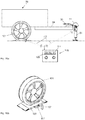
- FIG. 9 shows a side view ( Fig. 9a ) and a sectional view AA ( Fig. 9b ) through the side view of Fig. 9a
- a force measuring sensor 87 in the power flow of a support wheel 83 of a trailer drawbar of a trailer to be pulled (not shown) is arranged.
- the jockey wheel assembly comprises a jockey wheel 83, which is connected to a jockey wheel crank 85 via a variable-length standpipe 81. By rotating the Stitzradkurbel 85, the support wheel 83 can be raised or lowered by means of a threaded spindle 97.
- the support wheel 83 serves to support a trailer drawbar, if the trailer is not connected to a towing vehicle.
- a freestanding trailer can be determined by measuring the supporting force, which is derived via the Stützradanowski to the ground, the load before coupling a towing vehicle.
- one or more force measuring sensors 85 are arranged in a force flow path between the inner and outer standpipe 81, in particular in the head region of the support wheel arrangement.
- the force measuring sensor 87 is connected to an evaluation electronics unit 89 encapsulated in a weatherproof sensor housing 93. This determines from the sensor measurement data the occurring vertical load, which is displayed on a housing-side display unit 91.
- a membrane keypad disposed on the outer surface of the sensor housing 93 serves as a control member 91 to turn on and off the support load measuring device 79, perform calibration, and make other adjustments. By means of a warning lamp, an overload condition can be visually displayed.
- Fig. 10 a third embodiment of a support load device 51 according to the invention in the form of a standpipe which supports a ball socket 31 of a trailer 99.
- a trailer 99 which comprises a coupling frame 04, on which the ball socket 31 together with the brake lever 33 of the trailer hitch is arranged, and two wheels 101 has.
- the support load measuring device 51 comprises, in addition to a housing-side display unit, a portable display unit 105, which receives by means of a radio link 107 Stützlastmess flowers and displays on a display.
- measurement data of one or more wheel load scales 103 which are arranged under one or all wheels of the trailer 99, can be displayed in addition to the vertical load.
- the respective evaluation electronic units of the wheel load scales 103 are likewise connected to the portable display unit 105 via one or more radio links 107.
- a connection of wheel load scales 103 and support load measuring device 51 with a cable connection is conceivable, so that only one radio link 107 is required.
- the total load of the trailer 99 in sum of all wheel loads measured by the wheel load scales 103 on all wheels 101 and the drawbar support load determined by the support load measuring device 51 in a total load display 109 being represented.
- This can also be represented by a graphical or numerical representation of the distribution of the total load on the support points, ie on the individual wheels and the trailer hitch, such a load distribution diagram 111 before driving a statement on the observance of a maximum allowable Total load and the distribution of the load are, so that, for example, by optimized load distribution, the allowable vertical load of each support point observed and optimal loading of the trailer can be achieved.
- the wheel load can be detected by wheel load measuring devices integrated in the trailer 99, for example strain gauges on the wheel suspensions and one or more evaluation electronic units, and transmitted wirelessly or by wire to the support load measuring device.
- the wheel load scale 103 comprises a surface housing as a transfer bridge 115, on which a wheel of a trailer or a vehicle can move up and down.
- the scale surface 113 may be roughened or corrugated to improve the grip between the wheel and balance 103.
- the wheel load balance 103 comprises a wheel load evaluation and display unit 117, which may include a pressure sensor and an evaluation electronics together with the display unit 127 and control element 121.
- the wheel load balance 103 may comprise a volume of incompressible hydraulic fluid or a compressible gas volume, wherein a pressure sensor on a hydraulic 125 or gas diaphragm measure occurring wheel load pressure on the scale surface 113 indirectly by pressure measurement of the hydraulic fluid or the gas volume, evaluate by means of evaluation and by the Display unit 127 can display.
- the one or more controls 121 and the display unit 127 allow a local display and switching and calibration of the wheel load scales 103.
- the wheel load can be transmitted by means of a radio link 107 or wired by means of a Meßtheticstechnisch 121 to a portable display unit 105, so that together with the support load measuring device Total measurement of the trailer load is possible, with an uneven load distribution can be detected and corrected.
- the total weight of the trailer can be determined and transmitted via radio or wired to a display unit.
- the individual wheel load scales can first transmit the measurement results to the support load measuring device or directly to the display unit, wherein the measurement results of the wheel load scales and the support load measuring device can be added to determine the total weight.
- the total weight measurement of eg a motorhome or caravan is possible.
- a towing device can be applied, for example, with two strain gauges as a bridge circuit, one on the top and one on the bottom and / or on the left and right side surfaces of the trailer device for measuring bending and / or torsion.
- strain gauges can be applied on the top and bottom side, and in the case of torsion measurement on the side surfaces.
- strain gauges with a herringbone structure are to be preferred, in particular for torsion determination, which can determine both longitudinal and transversal length changes.
- the arrangement of four strain gauges on the top, bottom and the two side surfaces allows a combined torsion and deflection measurement. Since the strain gauge is applied directly to the towing hook, its suspension (mounting frame) or on the drawbar of a trailer, from the towing hook (or mounting frame) or the drawbar of the trailer is a sensor that absorbs the deformation by the vertical load and / or the torsional force , The resulting deformations are detected and amplified in a device connected to the strain gauge electronics. The amplified signals are then transmitted to a cockpit and displayed readable.
- the transmission can either be transmitted via a cable to the cockpit or to the vehicle electronics (ESP) or the transmission can be transmitted by radio to a display that you can hold in your hand and read at any time during loading.
- the electronics can be mounted or installed in a housing directly on the towing hook or on the drawbar, as well as in the vehicle.
- the driving or braking behavior of the trailer and the towing vehicle can be regulated or improved by means of the recorded measured values from the sensor of the towing hook or the trailer drawbar by evaluation and correction (by means of software) of the ESP or other controls.
Landscapes
- Engineering & Computer Science (AREA)
- Physics & Mathematics (AREA)
- General Physics & Mathematics (AREA)
- Transportation (AREA)
- Mechanical Engineering (AREA)
- Computer Networks & Wireless Communication (AREA)
- Chemical & Material Sciences (AREA)
- Analytical Chemistry (AREA)
- Combustion & Propulsion (AREA)
- Force Measurement Appropriate To Specific Purposes (AREA)
- Agricultural Machines (AREA)
Description
Die Erfindung betrifft eine Stützlastmessungsvorrichtung für eine ein Fahrzeug und einen Anhänger verbindbare Anhängevorrichtung.The invention relates to a support load measuring device for a vehicle and a trailer connectable hitch.
Als Stützlast ist eine Kraft definiert, die bei Anhängern mit geringem Achsabstand (zum Beispiel einachsige Pkw-Anhänger oder einem Achsenabstand unter einem Meter, Sattelzugauflieger, Zentralachsenanhänger) auf die Anhängervorrichtung des Zugfahrzeugs wirkt. Hersteller von Anhängern und Zugfahrzeugen schreiben maximal zulässige Stützlasten vor. Die tatsächliche Stützlast des Anhängers darf die maximal zulässige Stützlast des Zugfahrzeugs nicht überschreiten. In der Regel können Stützlasten bei PKW-Gespannen im Bereich zwischen 50 bis 150 Kilogramm und bei landwirtschaftlichen Geräten, und LKWs maximal 2 Tonnen betragen.A vertical load is defined as a force acting on trailers with a small center distance (for example, single-axle car trailers or less than one meter axle spacing, semi-trailer, central axle trailer) on the towing device of the towing vehicle. Manufacturers of trailers and towing vehicles prescribe maximum permissible jacking loads. The actual vertical load of the trailer must not exceed the maximum permissible vertical load of the towing vehicle. As a rule, supporting loads for passenger car combinations in the range between 50 and 150 kilograms and for agricultural equipment and trucks can amount to a maximum of 2 tons.
Der Gesetzgeber schreibt nach der StVZO §§ 42, 44 für PKW-Gespanne eine Mindeststützlast von 4% des Leergewichts des Anhängers vor. Hierzu können Gesamtlasten bei Anhängern jeweils so verteilt werden, dass eine Stützlast im zulässigen Bereich erreicht werden kann. Maßgeblich ist das Schwerpunktvormaß, das heißt, der Abstand zwischen Schwerpunkt beziehungsweise Lastangriffspunkt des Anhängers und Radaufstandspunkt, der sich mathematisch berechnen lässt. Um im Falle eines leeren Anhängers eine ausreichende Stützlast zu erreichen, wird deren Achse in der Regel hinter dessen Schwerpunk angebracht.The legislator prescribes according to the StVZO §§ 42, 44 for passenger car teams a minimum supporting load of 4% of the empty weight of the trailer. For this purpose, total loads for trailers can each be distributed so that a vertical load in the allowable range can be achieved. Decisive is the center of gravity, that is, the distance between the center of gravity or load application point of the trailer and wheel contact point, which can be calculated mathematically. In order to achieve a sufficient support load in the case of an empty trailer, the axis is usually mounted behind the Schwerpunk.
Bei Stützlasten sind zwei Extremfälle zu unterscheiden: Im Falle einer zu hohen Stützlast kann es beim Zugfahrzeug zu einer übergroßen Belastung der Hinterachsen, einer unzulässigen Entlastung der Vorderachsen und zu einer übermäßigen Beanspruchung der Anhängevorrichtung und der Montagepunkte führen. Des Weiteren kann eine zu hohe Stützlast beim Anhänger zu einer unzulässigen Belastung der Kugelkupplung oder zu einer unzulässigen Belastung der Deichsel führen, wobei Bruchgefahr herrscht. Auf der anderen Seite kann eine zu geringe Stützlast beim Zugfahrzeug zu einer gefährlichen Entlastung der Hinterachse führen, da die Hinterachse zumeist auch die Antriebsachse darstellt, und zu einer erhöhten Belastung der Vorderachse führen. Parallel hierzu führt eine zu geringe Stützlast beim Anhänger zu einer übergroßen Belastung der hinteren Achse des Anhängers und zu einer übermäßigen Zugbelastung der Kugelkupplung und der Deichsel, wobei wiederum Bruchgefahr aufgrund einer zu hohen Zugbeanspruchung herrscht. In der Regel sind höchstzulässige Stützlastgewichte auf jeder Anhängerkupplung aufgedruckt oder eingeprägt.For vertical loads, two extreme cases have to be distinguished: In the case of an excessively high load on the towing vehicle, excessive load on the rear axles, unacceptable load on the front axles and excessive strain on the rear axle may occur Hitch and the mounting points lead. Furthermore, too high a vertical load on the trailer can lead to an inadmissible load on the ball coupling or to an impermissible load on the drawbar, whereby there is a risk of breakage. On the other hand, too low a load on the towing vehicle can lead to a dangerous relief of the rear axle, since the rear axle usually also represents the drive axle, and lead to an increased load on the front axle. Parallel to this, too low a vertical load on the trailer leads to an excessive load on the rear axle of the trailer and to an excessive tensile load of the ball coupling and the drawbar, again there is a risk of breakage due to excessive tensile stress. As a rule, maximum permitted weights are printed or embossed on each trailer hitch.
Die konkrete Stützlast einer Anhängevorrichtung lässt sich aus dem Stand der Technik bekannt durch so genannte Stützlastwaagen bestimmen. Solche Stützlastwaagen sind in vielen Fällen als Federwaagen ausgeführt und werden zur richtigen Anwendung im Zugmaul einer Anhängerkupplung angesetzt. Eine weit verbreitete Messung mittels einer mechanischen Personenwaage und dem Bugrad eines Anhängers führt aufgrund der von der Deichsel wirkenden Hebelkräfte jedoch zu Fehlmessungen bis zu 15%.The concrete vertical load of a hitch can be determined from the prior art known as so-called support load scales. Such support load scales are designed in many cases as spring scales and are used for correct application in the towing jaw of a trailer hitch. However, a widespread measurement by means of a mechanical personal scale and the nose wheel of a trailer results in incorrect measurements of up to 15% due to the lever forces acting on the drawbar.
Aus dem Stand der Technik sind neben mechanischen Stützlastwaagen auch elektronische Stützlastwaagen bekannt, so beispielsweise aus der
Aus der
Eine gattungsgleiche Stützlastmessvorrichtung, die zwischen einem Anhänger und einem Zugfahrzeug angeordnet ist, ist aus der
In der
Die
The
Daneben betrifft die
In der
Aus der
Die
Ausgehend von dem oben genannten Stand der Technik ist es Aufgabe der Erfindung, eine Stützlastmessungsvorrichtung vorzuschlagen, die auf exakte Weise kompakt an der Anhängervorrichtung angebaut ist und zuverlässig die Stützlast auf elektronischem Wege ermitteln kann. Insbesondere ist es eine Aufgabe der Erfindung, eine permanente Überwachung der Stützlast während eines Beladevorgangs zu ermöglichen.Based on the above-mentioned prior art, it is an object of the invention to provide a support load measuring device that is compactly mounted on the trailer device in a precise manner and can reliably determine the vertical load by electronic means. In particular, it is an object of the invention to enable a permanent monitoring of the vertical load during a loading operation.
Gelöst werden die oben genannten Aufgaben durch eine Stützlastmessungsvorrichtung nach Anspruch 1. Vorteilhafte Ausführungsformen der Erfindung sind Gegenstand der abhängigen Ansprüche.The above objects are achieved by a support load measuring device according to
Erfindungsgemäß umfasst die Stützlastmessungsvorrichtung mindestens einen Kraftmesssensor, der den Kraftweg zwischen der Anhängervorrichtung und einem gegenstützenden Bezugsort zur Messung zumindest der über die Anhängervorrichtung übertragene Stützlast angeordnet ist, wobei der gegenstützende Bezugsort gemäß der Lehre des Anspruchs 1 bei einem abgekoppeltem Anhänger die Erdoberfläche darstellt. Des Weiteren umfasst die Stützlastmessungsvorrichtung erfindungsgemäß eine Auswerteelektronikeinheit in elektrischem Kontakt zu dem Kraftmesssensor zur Auswertung eines Stützlastmesswertes, wodurch Sensorsignale des Kraftmesssensors elektrisch ausgewertet werden können. Die Stützlastmessungsvorrichtung umfasst weiterhin eine Anzeigeneinheit zur elektrischen, digitalen oder analogen Anzeige der Stützlast, insbesondere zur Anzeige eines ungefährlichen bzw. kritischen Stützlastbereichs und eine Stromversorgungseinheit zur Versorgung der Auswerteelektronikeinheit mit elektrischer Energie. Schließlich ist die Stützlastmessungsvorrichtung in einem wetterfest ausgeführten Sensorgehäuse gekapselt, dass zumindest den Kraftmesssensor, die Auswerteelektronikeinheit und die Stromversorgungseinheit umfasst.According to the invention, the support load measuring device comprises at least one force measuring sensor, which determines the force path between the trailer device and a supporting reference location for measuring at least that transmitted via the trailer device Supporting load is arranged, wherein the supporting reference location according to the teaching of
Mit anderen Worten betrifft die Erfindung eine Stützlastmessungsvorrichtung, bei der unmittelbar an der Anhängervorrichtung im Kraftweg zwischen Anhängervorrichtung und Bezugsort (Erdoberfläche) eine Auflagekraft gemessen werden kann, die von einer Auswerteelektronikeinheit ausgewertet und an eine elektronische Anzeigeneinheit weitergeleitet werden kann, wobei die elektrischen Komponenten durch eine Stromversorgungseinheit mit Strom versorgt werden und zumindest Kraftmesssensor, Auswerteelektronikeinheit und Stromversorgungseinheit in einem wetterfest ausgeführten Sensorgehäuse gekapselt sind. Dabei ist die Stützlastmessungsvorrichtung als separate Vorrichtung ausgeführt, die temporär an der Anhängevorrichtung angekoppelt wird. Der Kraftmesssensor muss erfindungsgemäß zumindest soweit ausgelegt sein, um eine vertikal nach unten gerichtete Kraft ausgehend von der Anhängervorrichtung zu einem vertikal darunter liegenden Bezugsort messen zu können. Denkbar ist auch die Anwendung eines Kraftmesssensors oder mehrerer Kraftmesssensoren, die neben der Vertikalkraft Horizontal- oder Torsionskräfte messen können, um insbesondere horizontale Biegebeanspruchungen oder Verdrehungsbeanspruchungen (Torsionskräfte) der Anhängervorrichtung erfassen zu können.In other words, the invention relates to a support load measuring device in which a bearing force can be measured directly on the trailer device in the force path between trailer device and reference location (earth's surface), which can be evaluated by an evaluation electronics unit and forwarded to an electronic display unit, the electrical components by a Power supply unit are supplied with power and at least force measuring sensor, evaluation electronics unit and power supply unit are encapsulated in a weatherproof designed sensor housing. In this case, the support load measuring device is designed as a separate device, which is temporarily coupled to the hitch. According to the invention, the force-measuring sensor must at least be designed so as to measure a vertically downward force starting from the trailer device to a reference point located vertically below it to be able to. It is also conceivable to use a force measuring sensor or a plurality of force measuring sensors, which can measure horizontal or torsional forces in addition to the vertical force in order to be able to detect in particular horizontal bending stresses or torsional forces (torsional forces) of the trailer device.
Erfindungsgemäß umfasst die Auswerteelektronikeinheit eine Luftschnittstelle, so dass sie drahtlos mit einer zweiten Anzeigeeinheit, insbesondere mit einer portablen Anzeigeeinheit, mittels Funk, insbesondere Bluetooth, WLAN, ISM-Funk, Infrarot, Ultraschall oder vergleichbaren Drahtlosverbindungen zur Anzeige des Stützlastwertes verbindbar ist. Hierzu kann die Drahtlosschnittstelle insbesondere auf die Verwendung eines normierten Industrieprotokolls wie Bluetooth, dass bei Mobiltelefone oder portable Navigationssysteme häufig genutzt wird, WLAN, das über eine höhere Reichweite verfügt, oder einer sonstigen industriellen ISM-Funkkommunikation beruhen (ISM-Funk bedeutet ein Industrial, Scientific and Medical Band Funk, der von Hochfrequenzgeräten der Industrie, Wissenschaft oder Medizin im häuslichen oder ähnlichen Bereich benutzt wird und beispielsweise für Garagentoröffner vorgesehen sind, wobei Frequenzbereiche besonders im 433 MHz oder 2,4 GHz Band verwendet werden). Des Weiteren können auch nicht funkgebundene, sondern optisch oder akustisch übertragende Luftschnittstellen, wie Infrarot oder Ultraschall für die Informationsübermittlung zwischen Auswerteelektronikeinheit und einer portablen Anzeigeeinheit verwendet werden. Mittels einer portablen Anzeigeeinheit ist es insbesondere im Beladungsfall bequem möglich, im Rahmen eines Umladevorgangs innerhalb eines Anhängers dessen Gewicht so zu verteilen, dass ein kritischer Stützlastbereich aufgehoben werden kann, wobei die aktuelle Stützlast jederzeit mobil ablesbar ist. Zum anderen kann ohne Kabeleinwirkung beispielsweise eine Verbindung in den Cockpitbereich eines Fahrzeugs geschaffen werden, um im Fahrbetrieb laufend die Stützlast oder auch Torsions- oder andere Beanspruchungen der Anhängevorrichtung dem Fahrer sichtbar zu machen. Denkbar ist, dass hierzu besonders zugeschnittene Software in einem Mobiltelefon oder einem Navigationssystem, die über eine Bluetooth oder WLAN-Schnittstelle verfügen, genutzt wird, um die vom Sensor abgestrahlten Signale mobil sichtbar zu machen, so dass die mobile Anzeigeeinheit durch ein Mobiltelefon oder ein Navigationssystem durch Aufruf einer entsprechenden Software bereitgestellt wird.According to the invention, the evaluation electronics unit comprises an air interface so that it can be wirelessly connected to a second display unit, in particular to a portable display unit, by radio, in particular Bluetooth, WLAN, ISM radio, infrared, ultrasound or comparable wireless connections for displaying the support load value. For this purpose, the wireless interface can be based, in particular, on the use of a standardized industrial protocol, such as Bluetooth, which is frequently used in mobile phones or portable navigation systems, WLAN, which has a longer range, or other industrial ISM radio communication (ISM radio means an industrial, S cientific and M edical Band Radio used by industrial, scientific or medical high frequency devices in the domestic or similar field and intended, for example, for garage door openers, frequency ranges being used particularly in the 433 MHz or 2.4 GHz band). Furthermore, it is also possible to use air interfaces that are not radio-bound but optically or acoustically transmitting, such as infrared or ultrasound, for the transmission of information between the evaluation electronics unit and a portable display unit. By means of a portable display unit, it is easily possible, in particular in the load case, within a trailer within a trailer to distribute its weight so that a critical support load area can be canceled, the current support load is readable at any time mobile. On the other hand, without cable action For example, a connection to be created in the cockpit area of a vehicle in order to make the support load or even torsional or other stresses of the hitch the driver visible while driving continuously. It is conceivable for this purpose that specially tailored software in a mobile telephone or a navigation system, which have a Bluetooth or WLAN interface, be used to make the signals emitted by the sensor mobile visible, so that the mobile display unit by a mobile phone or a navigation system is provided by calling appropriate software.
Weiterhin erfindungsgemäß ist die Anzeigeneinheit eingerichtet, mit zumindest einer weiteren Messeinrichtung zur Bestimmung der Radlast an zumindest einem Rad eines Anhängers drahtlos oder drahtgebunden verbunden zu werden. Die Anzeigeneinheit kann in diesem Fall eine Radlast, insbesondere die Gesamtlast, bevorzugt grafisch mittels eines Lastverteilungsdiagramms anzeigen. So kann insbesondere eine portable Anzeigeneinheit mit einem Stützlastsensor und mit Radlastwaagen, die unter allen Rädern eines Anhängers platziert sind, mittels einer Funk- oder Kabelverbindung verbunden sein, um neben der Stützlast der Anhängerkupplung die Radlast der Räder anzuzeigen, wobei eine Summendarstellung die Gesamtlast des Anhängers als wichtiges Kriterium des zulässigen Ladezustands des Anhängers darstellt. Daneben kann eine grafische Darstellung der Lastverteilung auf die einzelnen Aufstützpunkte, d.h. der Radpositionen und der Anhängerauflage eine Information über die Ladungsverteilung innerhalb des Anhängers geben, so dass die zulässige Gesamtlast eingehalten und eine optimale Lastverteilung erreicht werden kann. Anstelle Radlastwaagen können innerhalb des Anhängers angeordnete Radlastmesseinrichtungen genutzt werden, auch können diese beispielsweise mittels einer Kabelverbindung mit dem Stützlastsensor verbunden sein.Furthermore, according to the invention, the display unit is set up to be connected to at least one further measuring device for determining the wheel load on at least one wheel of a trailer wirelessly or by wire. In this case, the display unit can display a wheel load, in particular the total load, preferably graphically by means of a load distribution diagram. In particular, a portable display unit with a support load sensor and wheel load scales placed under all wheels of a trailer may be connected by a radio or cable connection to indicate the wheel load of the wheels in addition to the trailer's tow load, with a totals representation of the trailer's total load as an important criterion of the permissible state of charge of the trailer. In addition, a graphical representation of the load distribution on the individual support points, ie the wheel positions and the trailer support information about the charge distribution within the trailer, so that the maximum load can be maintained and an optimal load distribution can be achieved. Instead wheel load scales arranged within the trailer wheel load measuring devices can be used, these can also be connected, for example by means of a cable connection with the support load sensor.
Nach einem ausgezeichneten Ausführungsbeispiel umfasst der Kraftmesssensor eine piezoresistive Messzelle, eine kapazitive Messzelle, eine induktive Messzelle oder einen Dehnungsmessstreifen. Jede der vorgenannten Sensorausführungen ermöglicht die exakte Messung einer Kraft zwischen der Anhängervorrichtung und einem Bezugsort, wobei diese Messung insbesondere indirekt beispielsweise über eine Bauteilverformung von Teilen der Anhängevorrichtung erfolgen kann. Insbesondere die Anwendung eines Dehnungsmessstreifens durch unmittelbare Applikation an einem Zughaken eines Fahrzeug oder einer Anhängerdeichsel eines Anhängers, zum Beispiel an einen Zugholm eines Wohnwagen oder eines Transportanhängers, wandelt den Zughaken oder die Zugdeichsel zu einem Stützlastsensor um. Bei der Anbringung eines oder mehrerer Dehnungsmessstreifen direkt am Zughaken oder an der Zugdeichsel wird somit unmittelbar ein Sensor, der aus Deichsel oder Anhänger besteht, ausgebildet. Bei Anwendung einer oder mehrerer elektrischer Messsensoren bietet es sich insbesondere an, zwei Messsensoren, insbesondere zwei Dehnungsmessstreifen als Brückenschaltung zu verschalten, wobei ein Messsensor auf der Oberseite und einer auf der Unterseite einer Anhängervorrichtung zur Messung der Durchbiegung und/oder Torsion appliziert werden kann. Die Verschaltung von zwei oder von vier Sensoren in einer Brückenschaltung erhöht die Genauigkeit und Sensitivität des Sensors, insbesondere bei gegenläufigen Beanspruchungskräften, die auf die Sensoren wirken. Wird der Sensor direkt am Zughaken, dessen Aufhängung (Montagerahmen) oder auch an der Zugdeichsel eines Anhängers appliziert, wird aus dem Zughaken oder dem Montagerahmen oder der Zugdeichsel des Anhängers ein Sensor, der die Verformung durch die Stützlast und/oder die Torsionskraft mit hoher Sensitivität aufnehmen kann. Die dadurch entstehenden Verformungen können in einer an dem Sensor angeschlossenen Elektronik erfasst und verstärkt werden. Die verstärkten Signale können anschließend auf ein Display einer Anzeigeeinheit übertragen und ablesbar angezeigt werden. Hierzu ist es denkbar, die Auswerteelektronikeinheit zum einen kompakt mit Sensor und Stromversorgungseinheit in einem Sensorgehäuse unterzubringen, als auch die Auswerteelektronikeinheit im Zugfahrzeug anzubringen, beziehungsweise einzubauen.According to an exemplary embodiment, the force measuring sensor comprises a piezoresistive measuring cell, a capacitive measuring cell, an inductive measuring cell or a strain gauge. Each of the aforementioned sensor embodiments allows the exact measurement of a force between the trailer device and a reference location, wherein this measurement can be done in particular indirectly, for example via a component deformation of parts of the hitch. In particular, the use of a strain gauge by direct application to a towing hook of a vehicle or a trailer drawbar of a trailer, for example to a towbar of a caravan or a transport trailer converts the towing hook or drawbar to a support load sensor. When attaching one or more strain gauges directly to the tow hook or to the drawbar thus directly a sensor that consists of drawbar or trailer is formed. When using one or more electrical measuring sensors, it is particularly appropriate to connect two measuring sensors, in particular two strain gauges as a bridge circuit, wherein a measuring sensor on the top and one on the underside of a trailer device for measuring the deflection and / or torsion can be applied. The interconnection of two or four sensors in a bridge circuit increases the accuracy and sensitivity of the sensor, especially with opposing stress forces acting on the sensors. If the sensor is applied directly to the hitch, its suspension (mounting frame) or to the drawbar of a trailer, the hitch or the mounting frame or the drawbar of the trailer from a sensor, the deformation by the vertical load and / or the torsional force with high sensitivity can record. The resulting deformations can in a connected to the sensor Electronics are recorded and amplified. The amplified signals can then be transmitted to a display of a display unit and displayed in a readable manner. For this purpose, it is conceivable to accommodate the evaluation electronics unit for a compact with sensor and power supply unit in a sensor housing, as well as to install or install the evaluation electronics unit in the towing vehicle.
Nach einem weiteren ausgezeichneten Ausführungsbeispiel ist der als Dehnungsmessstreifen ausgeführte Kraftmesssensor als Folien -, Dickschicht-, Metalldünnschicht-, Halbleiterdünnschicht-Dehnungsmessstreifen, insbesondere Siliziumdünnschicht-Dehnungsmessstreifen oder als Halbleiter-Diffusionswiderstand ausgeführt. Durch die Verwendung eines oder mehrerer Arten von Dehnungsmessstreifen kann abhängig von der Ausführung der Anhängevorrichtung und dem Aufbringungsort ein geeigneter Dehnungsmessstreifen zum unmittelbaren Applizieren auf der Anhängervorrichtung ausgewählt werden.According to a further exemplary embodiment, the force measuring sensor designed as a strain gauge is designed as foil, thick film, metal thin film, semiconductor thin film strain gauges, in particular silicon thin film strain gauges or as semiconductor diffusion resistance. By using one or more types of strain gauges, depending on the hitch design and location, a suitable strain gauge may be selected for immediate application to the hitch device.
Nach einem besonderen Ausführungsbeispiel sind mindestens zwei Kraftmesssensoren in der Vorrichtung umfasst, die gleich- oder verschiedenartig sein können und insbesondere in einer Brückenschaltung zur Auswertung der Stützlast verschaltet sein können. Durch Verschaltung der Sensoren in einer Brückenschaltung wird die Messgenauigkeit erheblich erhöht, sowie eine Redundanz bei Ausfall eines Sensors zur Erhöhung der Betriebssicherheit und der Langlebigkeit gewährleistet.According to a particular embodiment, at least two force measuring sensors are included in the device, which may be the same or different and in particular may be connected in a bridge circuit for evaluating the vertical load. By interconnecting the sensors in a bridge circuit, the measuring accuracy is considerably increased, as well as a redundancy in case of failure of a sensor to increase the reliability and longevity guaranteed.
Nach einem besonderen Ausführungsbeispiel sind ein oder mehrere Kraftmesssensoren, insbesondere mehrere Metallfolien-Dehnungsmessstreifen als Kraftmesssensoren mittels eines geeigneten Klebers oder mittels Dünnfilmtechnik oder durch thermisches Aufbringen oder Sputtern an anhängerlastig verformbare Teile der Anhängervorrichtung, insbesondere Kugelkopfträger, Anhängerhaken oder Deichselholm applizierbar, wobei die Kraftmesssensoren vom Sensorgehäuse gekapselt sind. Mit anderen Worten können insbesondere Metallfolien-Dehnungsmessstreifen unmittelbar durch Kleben oder durch Dünnfilmtechnik, beziehungsweise durch thermisches Aufdampfen oder Sputtern, unmittelbar auf verformbare Teile der Anhängervorrichtung zur Bestimmung der Stützlast, die sich direkt als eine Verformung des Teils der Anhängervorrichtung niederschlägt, appliziert werden, wobei die Sensoren in diesem Fall von einem Sensorgehäuse gekapselt sind, um sie vor Umwelteinflüssen zu schützen. Somit wird ein Teil der Anhängervorrichtung direkt als Messvorrichtung genutzt, um den Kraftfluss zwischen Anhängervorrichtung und Fahrzeug, beziehungsweise Anhängervorrichtung und Erdoberfläche, bestimmen zu können.According to a particular embodiment, one or more force measuring sensors, in particular a plurality of metal foil strain gauges as force measuring sensors by means of a suitable adhesive or by thin film technology or by thermal deposition or sputtering on trailer-load deformable parts of Trailer device, in particular ball head carrier, trailer hook or drawbar handle can be applied, wherein the force measuring sensors are encapsulated by the sensor housing. In other words, in particular, metal foil strain gauges can be directly applied by gluing or by thin film technique, or by thermal vapor deposition or sputtering, directly onto deformable parts of the trailer load suspension fixture which directly precipitates as a deformation of the trailer device part Sensors are encapsulated in this case by a sensor housing to protect it from environmental influences. Thus, a part of the trailer device is used directly as a measuring device in order to determine the power flow between trailer device and vehicle, or trailer device and ground surface.
Nach einem ausgezeichneten Ausführungsbeispiel kann der Kraftmesssensor zusätzlich oder mindestens ein zweiter Kraftmesssensor explizit eine weitere Kraftkomponente, insbesondere eine Torsionskraftkomponente oder eine Horizontalkraftkomponente, messen. Durch Verwendung eines zwei- oder mehrdimensionalen Kraftmesssensors oder der Verwendung von zwei oder mehreren Kraftmesssensoren, die Kräfte in verschiedenen Achsrichtungen aufnehmen können, können somit nicht nur die vertikal nach unten wirkende Stützlast sondern ebenfalls horizontal wirkende Kräfte, das heißt, Biegebeanspruchungen, beispielsweise bei einer Kurvenfahrt eines Zuggespanns oder Torsionskräfte, bei Verwindung der Anhängervorrichtung gemessen und angezeigt werden. Die Auswertung solcher Kraftkomponenten ist insbesondere im Betrieb, das heißt während einer Fahrt, wichtig, um Überlast in allen relevanten Beanspruchungsrichtungen der Anhängervorrichtung überwachen und daraufhin eventuell gegensteuern zu können.According to an excellent embodiment, the force measuring sensor additionally or at least one second force measuring sensor can explicitly measure a further force component, in particular a torsional force component or a horizontal force component. By using a two- or multi-dimensional force measuring sensor or the use of two or more force sensors that can absorb forces in different axial directions, not only the vertical down-acting support load but also horizontally acting forces, that is, bending stresses, for example when cornering a train or torsional forces are measured and displayed in twisting the trailer device. The evaluation of such force components is particularly important during operation, that is, while driving, important to monitor overload in all relevant directions of stress of the trailer device and then be able to take appropriate countermeasures.
In einem besonderen Ausführungsbeispiel umfasst die Auswerteelektronikeinheit eine Verstärker- und Auswerteelektronik, die sowohl eine Verstärkung des elektrischen Sensorsignals vornimmt, als auch eine Auswertung bezüglich des Stützlastwertes, insbesondere zumindest eines oder mehrerer kritischer Stützlastbereiche, vornimmt. Somit kann in diesem Ausführungsbeispiel die Auswerteelektronikeinheit zum einen eine Verstärkung der Sensorsignale vornehmen, beispielsweise um diese an eine entfernt befindliche Kraftfahrzeugelektronikeinheit, beispielsweise Bremseinheit oder ESP-Einheit, weiterzuleiten, als auch zum anderen die Sensorsignale auswerten, um diese auf einer Anzeigeneinheit darstellbar zu machen und hinsichtlich der Überschreitung von kritischen Werten zu überwachen, beispielsweise beim Auftreten einer zu hohen oder einer zu geringen Stützlast ein Warnsignal auszugeben.In a particular embodiment, the evaluation electronics unit comprises amplifier and evaluation electronics which both amplify the electrical sensor signal and also perform an evaluation with respect to the support load value, in particular at least one or more critical support load areas. Thus, in this embodiment, the evaluation electronics unit can make an amplification of the sensor signals, for example, to forward them to a remote motor vehicle electronics unit, such as brake unit or ESP unit, as well as to evaluate the sensor signals to make them displayable on a display unit and to monitor for the exceeding of critical values, for example, to issue a warning signal when too high or too low a vertical load occurs.
Hieran anschließend ist es insbesondere vorteilhaft, dass die Auswerteelektronikeinheit und/oder die Anzeigeneinheit einen optischen und/oder akustischen Warngeber zur Ausgabe eines Warnsignals bei Überschreiten zumindest eines kritischen Stützlastwertes umfasst. Insbesondere im Betrieb eines Fahrzeugs, aber auch bei einem stehenden Anhänger bzw. Zuggespann im Falle eines Belade- oder Endladevorgangs kann bei Überschreiten bzw. Unterschreiten einer kritischen Stützlast, insbesondere einer zu hohen bzw. einer zu niedrigen Stützlast, optisch wie auch akustisch ein Warnsignal ausgegeben werden, um den Belade- bzw. Endladevorgang zu unterbrechen oder im Falle einer laufenden Fahrt die Geschwindigkeit zu verringern und einen sicheren Fahrzustand herbeizuführen.Following this, it is particularly advantageous for the evaluation electronics unit and / or the display unit to comprise an optical and / or acoustic warning transmitter for outputting a warning signal when at least one critical supporting load value is exceeded. Particularly in the operation of a vehicle, but also in a stationary trailer or train in the case of loading or unloading a warning signal can be issued when exceeding or falling below a critical support load, especially too high or too low a vertical load, optically as well as acoustically in order to interrupt the loading or unloading process or, in the case of an ongoing journey, to reduce the speed and to ensure a safe driving condition.
Nach einem besonderen Ausführungsbeispiel ist die Auswerteelektronikeinheit elektrisch mit zumindest einer ersten Anzeigeeinheit, insbesondere mit einer im Sensorgehäuse, im Cockpitbereich eines ziehenden Fahrzeugs oder im Laderaum eines gezogenen Anhängers angeordneten Anzeigeeinheit zur Anzeige des Stützlastwertes verbunden. Mit anderen Worten kann in diesem Ausführungsbeispiel die Auswerteelektronikeinheit elektrisch, das heißt mittels leitender Kabelverbindung mit einer ersten Anzeigeeinheit verbunden sein, die entweder unmittelbar im Sensorgehäuse integriert, als auch im Bereich des ziehenden Fahrzeugs, insbesondere im Cockpitbereich oder im Ladebereich des gezogenen Anhängers, beispielsweise in der Stirnwand eines Anhängers, angebracht sein, um im Ladeverfahren, oder bei laufender Fahrt permanent die Stützlast anzuzeigen oder beim Ankuppeln des Anhängers an das ziehende Fahrzeug die momentan wirkende Stützlast anzuzeigen.According to a particular embodiment, the evaluation electronics unit is electrically connected to at least one first display unit, in particular one in the sensor housing, in the cockpit area of a towing vehicle or in the hold of a towed trailer arranged display unit connected to the display of the supporting load value. In other words, in this embodiment, the evaluation electronics unit can be electrically connected, ie by means of a conductive cable connection to a first display unit which is either integrated directly in the sensor housing or in the area of the towing vehicle, in particular in the cockpit area or in the loading area of the towed trailer, for example in FIG the front wall of a trailer, be attached to permanently display the support load in the loading process, or while the car is running or to display the currently acting support load when coupling the trailer to the towing vehicle.
Nach einem besonderen Ausführungsbeispiel umfasst die Auswerteelektronikeinheit eine Schnittstelle zu einem Fahrzeug-Datenbus, insbesondere zu einem CAN-Bus (Controller Area Network - ein asynchrones, serielles Bussystem insbesondere für Fahrzeuge), um Stützlastmessdaten an eine Fahrzeugelektronik, insbesondere zur Beeinflussung eines Stabilitäts- oder Antriebskontrollsystems, wie ESP, ASR oder ähnliches weiterzugeben. Durch Übermittlung der Sensordaten der Stützlastmessungsvorrichtung können insbesondere die Stabilität und das sichere Fahrverhalten eines Fahrzeugs beeinflussende Fahrzeugelektronikkomponenten über die auftretenden Stützlastkräfte unterrichtet werden. Diese können im Rahmen einer kontrollierten Fahrzeugsteuerung diese Sensordaten berücksichtigen. Insbesondere ESP (Elektronisches Stabilitätsprogramm für Fahrzeuge auch Electronic Stability Control genannt) oder ASR (Antischlupfregelung) und weitere Fahrerassistenzsysteme können unter Berücksichtigung auftretender Stützlast- aber auch Torsions- oder horizontaler Schwingkräfte gezielt auf die Fahrzeugdynamik Einfluss nehmen, um ein sicheres Fahrverhalten eines Fahrzeuggespanns zu gewährleisten. Hierzu koppelt die Auswerteelektronikeinheit über eine Fahrzeugelektronik-Schnittstelle unmittelbar die Daten des Sensors in die Fahrzeugelektronik ein.According to a particular embodiment, the evaluation electronics unit comprises an interface to a vehicle data bus, in particular to a CAN bus (Controller Area Network - an asynchronous, serial bus system, in particular for vehicles) to support load measurement data to a vehicle electronics, in particular for influencing a stability or drive control system How to pass ESP, ASR or similar. By transmitting the sensor data of the support load measuring device, in particular, the stability and the safe driving behavior of a vehicle influencing vehicle electronic components can be taught about the occurring supporting load forces. These can take this sensor data into consideration as part of a controlled vehicle control system. In particular, ESP (electronic stability program for vehicles also called electronic stability control) or ASR (traction control) and other driver assistance systems, taking into account occurring Stützlast- but also torsional or horizontal vibration forces specifically affect the vehicle dynamics to ensure safe driving behavior of a vehicle combination. This couples the Evaluation electronic unit via a vehicle electronics interface directly the data of the sensor in the vehicle electronics.
Nach einem besonders ausgezeichneten Ausführungsbeispiel ist die Auswerteelektronikeinheit elektrisch und/oder drahtlos mit Bedienelementen zur steuernden Bedienung, insbesondere zur Umschaltung einer Anzeigendarstellung auf einer Anzeigeneinheit verbunden. Somit lassen sich insbesondere an einer Anzeigeneinheit Bedienelemente anordnen, mit denen beispielsweise verschiedene Auswertedarstellungen der Stützlast, wie beispielsweise Balkendiagramm, numerische, digitale oder analoge Anzeige der Stützlast oder anderer Sensordaten dargestellt werden können. Des Weiteren lässt sich damit beispielsweise eine Umschaltung zwischen verschiedenen Sprachen, verschiedenen Einheitensystemen für Gewicht oder Kraft und andere Einstellungen, wie Selbsttests, Kalibrierung oder Einstellung von Vorhaltewerten zur Korrektur von Hebelwegen z.B. am Stützrad vornehmen, so dass eine Interaktion zwischen Sensorvorrichtung und Benutzer nicht nur im Wege einer Anzeige, sondern auch im Wege einer Bedienung durch den Benutzer ermöglicht werden kann. Ein Vorhaltewert bestimmt einen Hebelweg nicht unmittelbar an der Kupplung sondern in einem gewissen Abstand und beschreibt den durch die Hebewirkung einer Anhängerlast erzwungenen Hebelweg. Für eine genaue Messung müssen dieser Hebelweg und die entsprechende Verformung einstellbar bzw. kalibrierbar sein.According to a particularly excellent embodiment, the evaluation electronics unit is electrically and / or wirelessly connected to controls for controlling operation, in particular for switching a display display on a display unit. Thus, it is possible in particular to arrange operating elements on a display unit with which, for example, different evaluation representations of the supporting load, such as bar graph, numerical, digital or analog display of the vertical load or other sensor data can be represented. Furthermore, this can be used, for example, to switch between different languages, different weight or force unit systems, and other settings such as self-tests, calibration or setting of hold values to correct for leverage, e.g. make on the jockey wheel, so that an interaction between the sensor device and the user can be made not only by way of a display, but also in the way of an operation by the user. A reserve value does not determine a lever travel directly at the clutch but at a certain distance and describes the lever travel forced by the lifting action of a trailer load. For an accurate measurement, this lever travel and the corresponding deformation must be adjustable or calibratable.
Grundsätzlich kann die Stromversorgung für die Stützlastmessungsvorrichtung beliebig ausgeführt sein. In einem ausgezeichneten Ausführungsbeispiel ist die Stromversorgungseinheit ein Stecker-Kupplungsadapter zur Zwischenschaltung zwischen einer KFZ-Steckdose und einem Anhänger-Stecker, um elektrische Energie aus dem Fahrzeug und/oder dem Anhänger zu beziehen. In der Regel ist an jeder Anhängevorrichtung in der Nähe ein elektrischer Kupplungs- oder Buchsenanschluss, sowie am Anhänger ein Stecker zur Kontaktierung der Anhängerelektronik mit der Fahrzeugelektronik insbesondere zur Anzeige und Versorgung der rückwärtigen Beleuchtung des Anhängers, wie Bremslicht, Blinker oder Abschlusslicht vorhanden. Zur Versorgung der Stützlastmessungsvorrichtung mit elektrischer Energie ist es vorteilhaft, ein Zwischenadapterstück zwischen KFZ-Steckdose und Anhänger-Stecker vorzusehen, so dass bei angeschlossenem Anhänger an die KFZ-Steckdose des Fahrzeugs durch den Zwischenadapter Strom zum Betrieb der Stützlastmessungsvorrichtung abgezweigt werden kann. Somit braucht in der Stützlastmessungsvorrichtung keine interne Stromquelle vorgesehen werden.In principle, the power supply for the support load measuring device can be designed as desired. In an excellent embodiment, the power supply unit is a male coupling adapter for interposing between a vehicle electrical outlet and a trailer plug to provide electrical power from the vehicle and / or the trailer. As a rule, there is an electrical coupling or socket connection on each hitch nearby, as well as a plug for contacting the trailer electronics with the vehicle electronics, in particular for displaying and supplying the rear lighting of the trailer, such as brake light, turn signal or tail light available on the trailer. To supply the support load measuring device with electrical energy, it is advantageous to provide an intermediate adapter piece between the vehicle socket and trailer plug, so that when the trailer is connected to the vehicle power socket of the vehicle through the intermediate adapter power to operate the support load measuring device can be diverted. Thus, no internal power source need be provided in the support load measuring device.
Alternativ und/oder auch zusätzlich hierzu kann es vorteilhaft sein, dass die Stromversorgungseinheit eine Gleichstromquelle, insbesondere eine Batterie oder Akku und/oder eine Solarzelle, umfasst. Mittels einer in der Stromversorgungseinheit umfassten Gleichstromquelle und und/oder einer Solarzelle kann unabhängig von dem Vorhandensein eines Fahrzeugs, insbesondere unabhängig von dessen elektrischen Versorgungssystems ein Betrieb der Stützlastmessungsvorrichtung gewährleistet werden. Insbesondere unter Verwendung der Kombination einer Solarzelle und eines Ackus können ohne zusätzliche Kosten und Wartung eine langlebige elektrische Versorgung der Stützlastmessungsvorrichtung gewährleistet werden, so dass sich Wartungsaufwand und Betriebskosten der Stützlastmessungsvorrichtung gering halten lassen.Alternatively and / or additionally, it may be advantageous for the power supply unit to comprise a DC power source, in particular a battery or rechargeable battery and / or a solar cell. By means of a DC source and / or a solar cell included in the power supply unit, operation of the support load measuring device can be ensured independently of the presence of a vehicle, in particular independently of its electrical supply system. In particular, using the combination of a solar cell and an Ackus, a long-lasting electrical supply of the support load measuring device can be ensured without additional costs and maintenance, so that maintenance and operating costs of the support load measuring device can be kept low.
Ein mögliches Verfahren zur Ausrüstung einer bestehenden Anhängevorrichtung mit einer Stützlastmessungsvorrichtung kann die Schritte umfassen:
- unmittelbares Applizieren zumindest eines Kraftmesssensors an einer Anhängevorrichtung im Kraftweg zwischen Anhängevorrichtung und gegenstützendem Bezugsort, (insbesondere Erdoberfläche oder Abstützfläche am ziehenden Fahrzeug);
- elektrisches Verbinden des Kraftmesssensors mit einer Auswerteelektronikeinheit;
- Kapseln von Kraftmesssensor und Auswerteelektronikeinheit in einem Sensorgehäuse, das an der Anhängevorrichtung angeordnet ist.
- directly applying at least one force measuring sensor to a hitch in the force path between the hitch and the supporting reference location, (in particular earth surface or supporting surface on the towing vehicle);
- electrically connecting the force measuring sensor to an evaluation electronics unit;
- Capsules of force measuring sensor and evaluation electronic unit in a sensor housing, which is arranged on the hitch.
Mittels einer Nachrüstmöglichkeit lassen sich bereits bestehende Anhängevorrichtungen nachrüsten, oder in Produktion befindliche Anhängevorrichtungen mit einer Stützlastmessungsvorrichtung ausstatten. Dabei sind nur geringe oder keine konstruktiven Änderungen der bereits bestehenden Anhängevorrichtung notwendig, lediglich die direkt messenden Kraftmesssensoren werden unmittelbar an kraftführende Teile der Anhängevorrichtung, die sich unter Stützlast verformen können, angeordnet, und ein wetterfestes Sensorgehäuse wird zur Kapselung von Kraftmesssensoren und der Auswerteelektronikeinheit an der Anhängevorrichtung angeordnet. Somit ermöglicht das Nachrüsten eine einfache und kostengünstige, sowie ohne besondere Hilfsmittel auszuführende Möglichkeit bereits bestehender Anhängevorrichtungen, sei es Zughaken, Kugelkopfanhängevorrichtungen, Deichsel-Klauenmaul-Anhängevorrichtungen oder sonstigen Anhängervorrichtungen mittels einer Stützlastmessungsvorrichtung vor.By means of a retrofit possibility can be retrofitted existing hitches, or equip hitches in production equip with a support load measuring device. In this case, only small or no structural changes to the existing hitch are necessary, only the direct measuring force measuring sensors are directly to force-bearing parts of the hitch, which can deform under a vertical load, arranged, and a weatherproof sensor housing is used to encapsulate force measuring sensors and the evaluation electronics unit on the Hitch arranged. Thus, the retrofitting allows a simple and cost-effective, and to be carried out without special aids possibility already existing hitches, be it tow hook, ball hitch, drawbar jaw hitch or other trailer devices by means of a support load measuring device before.
Im Folgenden wird die Erfindung anhand von Zeichnungen, die verschiedene Ausführungsbeispiele darstellen, näher erläutert.In the following the invention will be explained in more detail with reference to drawings which illustrate various embodiments.
Weitere Vorteile ergeben sich aus der folgenden Zeichnungsbeschreibung. In der Zeichnung sind in den Figurne 1 bis 3, 5 und 6 mögliche Stütlastmessvorrichtungen und in den
Es zeigen:
-
Fig. 1 : In schematischer dreidimensionaler Perspektive einen Anhängerkupplungsrahmen eines ziehenden Fahrzeugs; -
Fig. 2 : In Dreitafelprojektion ein eine Stützlastmessungsvorrichtung an einer Anhängerkupplung; -
Fig. 3 : Einen Schnitt A-A durchFig. 2c der Stützlastmessvorrichtung derFig. 2 ; -
Fig. 4 : Schematisch eine Ansicht einer portablen Anzeigeeinheit; -
Fig. 5 : Einen Deichselrahmen, mit einer weiteren Stützlastmessungsvorrichtung; -
Fig. 6 : Ein Schnitt B-B derFig. 5 durch die Stützlastmessungsvorrichtung derFig. 5 ; -
Fig. 7 : Ein erstes Ausführungsbeispiel einer Stützlastmessungsvorrichtung gemäß der Erfindung für eine Kugelkopf-Anhängerkupplung; -
Fig. 8 : Schematisch ein Zuggespann mit einer Stützlastmessungsvorrichtung mit einer portablen Anzeigeeinheit. -
Fig. 9 : Ein zweites Ausführungsbeispiel einer Stützlastmessungsvorrichtung gemäß der Erfindung für ein Stützrad eines Anhängers; -
Fig. 10 : Ein drittes Ausführungsbeispiel einer Stützlastmessungsvorrichtung gemäß der Erfindung mit Radlastwaagen zur Bestimmung der Gesamtlast eines Anhängers; -
Fig. 11 : Eine Radlastwaage mit Überfahrbrücke zur Verwendung in dem dritten Ausführungsbeispiel gemäß der Erfindung.
-
Fig. 1 : In schematic three-dimensional perspective, a trailer hitch frame of a towing vehicle; -
Fig. 2 In three-panel projection, a support load measuring device on a trailer hitch; -
Fig. 3 : A cut AA throughFig. 2c the support load measuring device ofFig. 2 ; -
Fig. 4 : Schematically a view of a portable display unit; -
Fig. 5 : A drawbar frame, with another support load measuring device; -
Fig. 6 : A cut BB theFig. 5 by the support load measuring device ofFig. 5 ; -
Fig. 7 A first embodiment of a support load measuring device according to the invention for a ball-hitch trailer coupling; -
Fig. 8 : Schematically a train combination with a support load measuring device with a portable display unit. -
Fig. 9 A second embodiment of a support load measuring device according to the invention for a support wheel of a trailer; -
Fig. 10 A third embodiment of a support load measuring device according to the invention with wheel load scales for determining the total load of a trailer; -
Fig. 11 A wheel load scale with a transfer bridge for use in the third embodiment according to the invention.
In
So ist in
In
Des Weiteren zeigt
Daneben zeigt
Des Weiteren zeigt
Schließlich stellt
Eine Anhängevorrichtung kann beispielsweise mit zwei Dehnungsmessstreifen als Brückenschaltung, einer auf der Oberseite und einer auf der Unterseite und/oder auf den linken und rechten Seiteflächen der Anhängervorrichtung zur Messung von Biegung und/oder Torsion appliziert werden. Im Falle einer Biegungsmessung können Dehnungsmessstreifen auf Ober- und Unterseite, bei Torsionsmessung auf den Seitenflächen appliziert werden. Hierbei sind Dehnungsmessstreifen mit Fischgrätenstruktur insbesondere für die Torsionsbestimmung zu bevorzugen, die sowohl longitudinale als auch transversale Längenänderungen bestimmen können.A towing device can be applied, for example, with two strain gauges as a bridge circuit, one on the top and one on the bottom and / or on the left and right side surfaces of the trailer device for measuring bending and / or torsion. In the case of a bending measurement, strain gauges can be applied on the top and bottom side, and in the case of torsion measurement on the side surfaces. In this case strain gauges with a herringbone structure are to be preferred, in particular for torsion determination, which can determine both longitudinal and transversal length changes.
Insbesondere die Anordnung von vier Dehnungsmessstreifen auf Ober-, Unterseite sowie den beiden Seitenflächen ermöglicht eine kombinierte Torsions- und Durchbiegungsmessung. Da der Dehnungsmessstreifen direkt am Zughaken, deren Aufhängung (Montagerahmen) oder auch an der Zugdeichsel eines Anhängers appliziert wird, wird aus dem Zughaken (oder Montagerahmen) oder der Zugdeichsel des Anhängers ein Sensor, der die Verformung durch die Stützlast und/oder die Torsionskraft aufnimmt. Die dadurch entstehenden Verformungen werden in einer an den Dehnungsmessstreifen angeschlossene Elektronik erfasst und verstärkt. Die verstärkten Signale werden dann auf ein Cockpit übertragen und ablesbar angezeigt. Die Übertragung kann entweder über ein Kabel bis ins Cockpit oder an die Fahrzeugelektronik (ESP) übertragen werden oder die Übertragung kann per Funk an ein Display übermittelt werden, das man in Händen halten und beim Beladen jederzeit ablesen kann. Die Elektronik kann in einem Gehäuse direkt am Zughaken oder an der Zugdeichsel sowohl als auch im Fahrzeug angebracht, beziehungsweise eingebaut werden. Das Fahr- beziehungsweise Bremsverhalten des Anhängers und des Zugfahrzeugs kann mittels der aufgenommenen Messwerte aus dem Sensor des Zughakens oder der Anhängerdeichsel durch Auswertung und Korrektur (mittels Software) der ESP oder anderen Steuerungen geregelt beziehungsweise verbessert werden.In particular, the arrangement of four strain gauges on the top, bottom and the two side surfaces allows a combined torsion and deflection measurement. Since the strain gauge is applied directly to the towing hook, its suspension (mounting frame) or on the drawbar of a trailer, from the towing hook (or mounting frame) or the drawbar of the trailer is a sensor that absorbs the deformation by the vertical load and / or the torsional force , The resulting deformations are detected and amplified in a device connected to the strain gauge electronics. The amplified signals are then transmitted to a cockpit and displayed readable. The transmission can either be transmitted via a cable to the cockpit or to the vehicle electronics (ESP) or the transmission can be transmitted by radio to a display that you can hold in your hand and read at any time during loading. The electronics can be mounted or installed in a housing directly on the towing hook or on the drawbar, as well as in the vehicle. The driving or braking behavior of the trailer and the towing vehicle can be regulated or improved by means of the recorded measured values from the sensor of the towing hook or the trailer drawbar by evaluation and correction (by means of software) of the ESP or other controls.
Durch die Messung direkt am Zughaken oder der Zugdeichsel wird eine genaue Messung erreicht, die elektronisch angezeigt beziehungsweise ausgewertet werden kann.By measuring directly on the towing hook or the drawbar an accurate measurement is achieved, which can be displayed or evaluated electronically.
Claims (11)
- Towball load measuring device (51, 79) temporarily couplable to a trailer device for an unhitched trailer (73, 99) in the force path between trailer device and the ground surface, comprising- at least one force measurement sensor (57, 87) arranged in the force path between the trailer device and the ground surface for measuring at least the towball load transmitted via the trailer device;- an electronic evaluation unit (63, 89) in electrical contact with the force measurement sensor (57, 87) for evaluating a measured towball load value;- at least one display unit (13, 65, 77, 95, 105) for displaying the towball load;- a power supply unit for supplying the electronic evaluation unit (63, 89) with electrical energy;- a sensor housing (09, 41, 61, 93) of weatherproof design comprising at least the force measurement sensor (57, 87), the electronic evaluation unit (63, 89) and the power supply unit,characterized in
that the electronic evaluation unit (63, 89) comprises an air interface of a transmission path (107) such that it is wirelessly connectable to a second, in particular portable display unit (13, 65, 77, 95, 105) by radio (13) for displaying the towball load value, and the display unit (13, 65, 77, 95, 105) is connectable wirelessly or wired to at least one further measuring device (103) for determining a wheel load at at least one wheel (101) of a trailer (73, 99) in order to make a display of a wheel load visible. - Device (51, 79) according to claim 1,
characterized in
that the force measurement sensor (57, 87) comprises a piezoresistive measuring cell, a capacitive measuring cell, an inductive measuring cell or a strain gauge. - Device (51, 79) according to claim 2,
characterized in
that the strain gauge is a foil, thick-film, metal thin-film or semiconductor thin-film strain gauge or a semiconductor diffusion resistor. - Device (51, 79) according to claim 2 or 3,
characterized in
that at least two force measurement sensors (57, 87) are comprised which can be of the same or of different type and in particular are connected in a bridge circuit for evaluation of the towball load. - Device (51, 79) according to one of the preceding claims,
characterized in
that the device comprises a spherical head (59) connected via an upright tube (53) to a foot (55), where a force measurement sensor (57) is arranged at the upper connecting point between spherical head (59) and upright tube (53). - Device (51, 79) according to one of the preceding claims,
characterized in
that the device comprises a support wheel (83), a variable-length upright tube (81) and a support wheel crank (85) for forming a support wheel arrangement, where the support wheel (83) is connected via the variable-length upright tube (81) to the support wheel crank (85), and the force measurement sensor (87) is arranged in a force path between inner and outer upright tube (81), in particular in the top region of the support wheel arrangement. - Device (51, 79) according to one of the preceding claims,
characterized in
that the force measurement sensor (57, 87) can measure additionally, or at least one further force measurement sensor (57, 87) can measure explicitly, an additional force component, in particular a torsion force component. - Device (51, 79) according to one of the preceding claims,
characterized in
that the electronic evaluation unit (63, 89) comprises amplifying and evaluation electronics which perform both an amplification of the electric sensor signal and an evaluation relating to the towball load value, in particular at least one or more critical towball load ranges. - Device (51, 79) according to claim 8,
characterized in
that the electronic evaluation unit (63, 89) and/or the display unit (13, 65, 77, 95, 105) comprises a visual and/or acoustic warning device for emitting a warning signal when at least one critical towball load value is exceeded. - Device (51, 79) according to one of the preceding claims,
characterized in
that the electronic evaluation unit (63, 89) is connected electrically conductively and/or wirelessly to operating elements (15, 67, 91) for controlling operation, in particular for switching over a display shown on a display unit (13, 65, 95, 105). - Device (51, 79) according to one of the preceding claims,
characterized in
that the power supply unit comprises a plug coupling adapter for insertion between a vehicle socket and a trailer plug in order to draw electrical energy from the vehicle (71) or the trailer (73, 99), and/or the power supply unit comprises a direct-current source, in particular a normal or rechargeable battery and/or a solar cell.
Applications Claiming Priority (2)
| Application Number | Priority Date | Filing Date | Title |
|---|---|---|---|
| DE102009035701 | 2009-07-30 | ||
| DE102010004336A DE102010004336A1 (en) | 2009-07-30 | 2010-01-11 | Support load measuring device and retrofit method for a vehicle hitch |
Publications (3)
| Publication Number | Publication Date |
|---|---|
| EP2280263A2 EP2280263A2 (en) | 2011-02-02 |
| EP2280263A3 EP2280263A3 (en) | 2012-01-18 |
| EP2280263B1 true EP2280263B1 (en) | 2019-05-15 |
Family
ID=43027563
Family Applications (1)
| Application Number | Title | Priority Date | Filing Date |
|---|---|---|---|
| EP10170101.9A Active EP2280263B1 (en) | 2009-07-30 | 2010-07-20 | Supporting load measuring device and retrofitting method for a vehicle trailer device |
Country Status (2)
| Country | Link |
|---|---|
| EP (1) | EP2280263B1 (en) |
| DE (1) | DE102010004336A1 (en) |
Families Citing this family (22)
| Publication number | Priority date | Publication date | Assignee | Title |
|---|---|---|---|---|
| DE202011103345U1 (en) | 2011-03-23 | 2012-06-25 | Westfalia-Automotive Gmbh | Control unit for a trailer hitch and trailer hitch with a control unit |
| DE102011076392A1 (en) * | 2011-05-24 | 2012-11-29 | Robert Bosch Gmbh | Arrangement for connecting a towing vehicle with a trailer |
| DE202011105552U1 (en) * | 2011-05-31 | 2012-09-05 | Westfalia-Automotive Gmbh | Trailer coupling with a sensor device and sensor device therefor |
| US20130076497A1 (en) * | 2011-09-23 | 2013-03-28 | Alan D. Sheidler | Vehicle arrangement responsive to amount of material in a towed vehicle |
| DE102011117519A1 (en) * | 2011-11-03 | 2013-05-08 | Westfalia-Automotive Gmbh | Trailer coupling with a force sensor |
| DE102011120651A1 (en) * | 2011-12-09 | 2013-06-13 | Westfalia-Automotive Gmbh | Control unit and trailer coupling for communication with an operator panel |
| DE102012012321B3 (en) * | 2012-06-20 | 2013-08-08 | Volkswagen Aktiengesellschaft | Motor car has detection devices for detecting trailer hitch vertical load acting over trailer coupling, and control unit that locks parking brake if detected vertical load data exceeds preset vertical load value |
| DE102013021473A1 (en) | 2013-12-17 | 2015-06-18 | Steffen Klinger | Support load monitoring system |
| GB2543388B (en) * | 2014-08-08 | 2018-08-15 | Jaguar Land Rover Ltd | Towing stability |
| DE102014117712A1 (en) * | 2014-12-01 | 2016-06-02 | Westfalia-Automotive Gmbh | Trailer coupling with a sensor |
| DE102016200732B3 (en) * | 2016-01-20 | 2017-06-29 | Schaeffler Technologies AG & Co. KG | Measuring arrangement for force or torque measurement for a machine element and machine element arrangement with such a measuring arrangement |
| EP3379222B1 (en) | 2017-03-22 | 2020-12-30 | Methode Electronics Malta Ltd. | Magnetoelastic based sensor assembly |
| CN106915274A (en) * | 2017-03-24 | 2017-07-04 | 深圳腾势新能源汽车有限公司 | The charging method and system of a kind of electric automobile |
| US10960719B2 (en) | 2018-01-29 | 2021-03-30 | Progress Mfg. Inc. | Apparatus and method for measuring force on weight distribution hitches |
| US11221262B2 (en) | 2018-02-27 | 2022-01-11 | Methode Electronics, Inc. | Towing systems and methods using magnetic field sensing |
| US11135882B2 (en) | 2018-02-27 | 2021-10-05 | Methode Electronics, Inc. | Towing systems and methods using magnetic field sensing |
| US11084342B2 (en) | 2018-02-27 | 2021-08-10 | Methode Electronics, Inc. | Towing systems and methods using magnetic field sensing |
| EP3758959A4 (en) | 2018-02-27 | 2022-03-09 | Methode Electronics, Inc. | Towing systems and methods using magnetic field sensing |
| US11491832B2 (en) | 2018-02-27 | 2022-11-08 | Methode Electronics, Inc. | Towing systems and methods using magnetic field sensing |
| DE102018106855A1 (en) * | 2018-03-22 | 2019-09-26 | Wabco Gmbh | Measuring device for measuring forces and / or moments between a motorized vehicle and a trailer or attachment pulled or pushed by it |
| DE102018106856A1 (en) * | 2018-03-22 | 2019-09-26 | Wabco Gmbh | Measuring device for measuring forces and / or moments between a motorized vehicle and a trailer or attachment pulled or pushed by it |
| US10946710B2 (en) | 2018-08-08 | 2021-03-16 | Toyota Motor Engineering & Manufacturing North America, Inc. | Systems and methods for alerting drivers of excessive tongue weight |
Citations (3)
| Publication number | Priority date | Publication date | Assignee | Title |
|---|---|---|---|---|
| DE9400547U1 (en) * | 1994-01-14 | 1994-03-17 | Nestler Guenther | Device for connecting trailers and the like |
| GB2348289A (en) * | 1999-12-16 | 2000-09-27 | Adrian Leslie Ward | Device for indicating the weight to be exerted by the tow hitch of a towed vehicle |
| GB2352524A (en) * | 1999-07-23 | 2001-01-31 | Michelle Louise Dagnall | Trailer noseweight indicator |
Family Cites Families (6)
| Publication number | Priority date | Publication date | Assignee | Title |
|---|---|---|---|---|
| GB9907523D0 (en) * | 1999-04-01 | 1999-05-26 | Evans Kenneth S | Tow coupling sensor |
| DE10211572A1 (en) * | 2002-03-15 | 2003-10-02 | Bernd Basteck | Support load monitor system for vehicle trailers has pressure measuring device operating continuously with the coupling unit |
| DE102004029295A1 (en) * | 2004-06-17 | 2006-02-02 | Deere & Company, Moline | Device for detecting a vertical load |
| EP1627803A1 (en) * | 2004-08-19 | 2006-02-22 | Bradley Doublelock Limited | Trailers |
| DE102004058829A1 (en) | 2004-12-06 | 2006-06-08 | Heßmann, Stefan | Support forces measuring device for e.g. trailers, includes measuring unit for measuring support forces at clutch and axles of towing vehicle and drawbar of trailer, and indicator for indicating the measured support forces |
| DE102005030441A1 (en) * | 2005-06-30 | 2007-01-04 | Guido Weckelmann | Weighing scales at the towing link between a tractor vehicle and a trailer, to show the weight on the tow bar as the trailer is loaded, has a joint showing the angular shift between the tow bar and the shaft and a sliding pin indicator |
-
2010
- 2010-01-11 DE DE102010004336A patent/DE102010004336A1/en active Pending
- 2010-07-20 EP EP10170101.9A patent/EP2280263B1/en active Active
Patent Citations (3)
| Publication number | Priority date | Publication date | Assignee | Title |
|---|---|---|---|---|
| DE9400547U1 (en) * | 1994-01-14 | 1994-03-17 | Nestler Guenther | Device for connecting trailers and the like |
| GB2352524A (en) * | 1999-07-23 | 2001-01-31 | Michelle Louise Dagnall | Trailer noseweight indicator |
| GB2348289A (en) * | 1999-12-16 | 2000-09-27 | Adrian Leslie Ward | Device for indicating the weight to be exerted by the tow hitch of a towed vehicle |
Also Published As
| Publication number | Publication date |
|---|---|
| EP2280263A3 (en) | 2012-01-18 |
| DE102010004336A1 (en) | 2011-03-03 |
| EP2280263A2 (en) | 2011-02-02 |
Similar Documents
| Publication | Publication Date | Title |
|---|---|---|
| EP2280263B1 (en) | Supporting load measuring device and retrofitting method for a vehicle trailer device | |
| EP2492173B1 (en) | Trailer, tractor and tractor-trailer composed of same | |
| EP2589503B1 (en) | Trailer coupling with a force sensor | |
| EP2801488B1 (en) | tow hitch with an evaluation device | |
| DE102014001031A1 (en) | Method and device for assisted loading of a motor vehicle | |
| DE102016109425A1 (en) | Measuring module with force and acceleration sensors for determining the weight of a towing vehicle coupled to a towing vehicle | |
| DE102015008390A1 (en) | Method and system for weighing a semitrailer connected to a towing vehicle | |
| DE102006037428B4 (en) | Wheel suspension for a motor vehicle | |
| DE102017103777A1 (en) | Stabilization device and stabilization method | |
| DE102012113015A1 (en) | A device for emergency signaling in a vehicle crash and method of operation | |
| EP2787330B1 (en) | Weighing system and method for weighing a load of an articulated tipper vehicle | |
| DE202010000799U1 (en) | Support load measuring device for a vehicle hitch | |
| DE102004019624B3 (en) | Vehicle axle load measurement unit has processor storing axle sensor load values from different load conditions to generate load/axle load function for load status determination | |
| DE102011088071A1 (en) | Device for reporting load anomaly of commercial vehicle, has sensor unit, which responds to parameter that is representative for sloping position angle or load quantity carried by commercial vehicle | |
| DE3612053A1 (en) | Trailer coupling | |
| WO2007112718A1 (en) | Weighing module of a wheel loader | |
| DE102008028913B4 (en) | Monitoring device of a tractor-trailer combination | |
| EP0607855A1 (en) | Device for measuring or indicating the loading state of a semi-trailer | |
| DE102016109424A1 (en) | Measuring module with spring-mass system for weight determination | |
| DE102017114168A1 (en) | Sensor device for detecting the force acting on a trailer hitch forces and trailer hitch with this | |
| DE102020126622B4 (en) | DETERMINING VEHICLE AND TRAILER LOAD | |
| DE102004058829A1 (en) | Support forces measuring device for e.g. trailers, includes measuring unit for measuring support forces at clutch and axles of towing vehicle and drawbar of trailer, and indicator for indicating the measured support forces | |
| DE102010050683A1 (en) | Truck with deformation sensor in the tilting cylinder | |
| DE202007008391U1 (en) | Trailer e.g. caravan, coupling for e.g. passenger car, has measuring device determining support load weight of trailer, where measuring device is arranged above ball socket of trailer towing bar | |
| WO2022179839A1 (en) | Tongue weight measurement |
Legal Events
| Date | Code | Title | Description |
|---|---|---|---|
| PUAI | Public reference made under article 153(3) epc to a published international application that has entered the european phase |
Free format text: ORIGINAL CODE: 0009012 |
|
| AK | Designated contracting states |
Kind code of ref document: A2 Designated state(s): AL AT BE BG CH CY CZ DE DK EE ES FI FR GB GR HR HU IE IS IT LI LT LU LV MC MK MT NL NO PL PT RO SE SI SK SM TR |
|
| AX | Request for extension of the european patent |
Extension state: BA ME RS |
|
| PUAL | Search report despatched |
Free format text: ORIGINAL CODE: 0009013 |
|
| AK | Designated contracting states |
Kind code of ref document: A3 Designated state(s): AL AT BE BG CH CY CZ DE DK EE ES FI FR GB GR HR HU IE IS IT LI LT LU LV MC MK MT NL NO PL PT RO SE SI SK SM TR |
|
| AX | Request for extension of the european patent |
Extension state: BA ME RS |
|
| RIC1 | Information provided on ipc code assigned before grant |
Ipc: B60D 1/58 20060101ALI20111209BHEP Ipc: G01L 5/13 20060101AFI20111209BHEP Ipc: G01G 19/12 20060101ALI20111209BHEP |
|
| 17P | Request for examination filed |
Effective date: 20120718 |
|
| RAP1 | Party data changed (applicant data changed or rights of an application transferred) |
Owner name: DIEMER, HERR ANDREAS Owner name: HEIN, HERR THOMAS |
|
| 17Q | First examination report despatched |
Effective date: 20141203 |
|
| STAA | Information on the status of an ep patent application or granted ep patent |
Free format text: STATUS: EXAMINATION IS IN PROGRESS |
|
| GRAP | Despatch of communication of intention to grant a patent |
Free format text: ORIGINAL CODE: EPIDOSNIGR1 |
|
| STAA | Information on the status of an ep patent application or granted ep patent |
Free format text: STATUS: GRANT OF PATENT IS INTENDED |
|
| INTG | Intention to grant announced |
Effective date: 20181221 |
|
| GRAS | Grant fee paid |
Free format text: ORIGINAL CODE: EPIDOSNIGR3 |
|
| GRAA | (expected) grant |
Free format text: ORIGINAL CODE: 0009210 |
|
| STAA | Information on the status of an ep patent application or granted ep patent |
Free format text: STATUS: THE PATENT HAS BEEN GRANTED |
|
| AK | Designated contracting states |
Kind code of ref document: B1 Designated state(s): AL AT BE BG CH CY CZ DE DK EE ES FI FR GB GR HR HU IE IS IT LI LT LU LV MC MK MT NL NO PL PT RO SE SI SK SM TR |
|
| REG | Reference to a national code |
Ref country code: CH Ref legal event code: EP Ref country code: GB Ref legal event code: FG4D Free format text: NOT ENGLISH |
|
| REG | Reference to a national code |
Ref country code: DE Ref legal event code: R096 Ref document number: 502010015993 Country of ref document: DE |
|
| REG | Reference to a national code |
Ref country code: IE Ref legal event code: FG4D Free format text: LANGUAGE OF EP DOCUMENT: GERMAN |
|
| REG | Reference to a national code |
Ref country code: NL Ref legal event code: MP Effective date: 20190515 |
|
| REG | Reference to a national code |
Ref country code: LT Ref legal event code: MG4D |
|
| PG25 | Lapsed in a contracting state [announced via postgrant information from national office to epo] |
Ref country code: SE Free format text: LAPSE BECAUSE OF FAILURE TO SUBMIT A TRANSLATION OF THE DESCRIPTION OR TO PAY THE FEE WITHIN THE PRESCRIBED TIME-LIMIT Effective date: 20190515 Ref country code: NL Free format text: LAPSE BECAUSE OF FAILURE TO SUBMIT A TRANSLATION OF THE DESCRIPTION OR TO PAY THE FEE WITHIN THE PRESCRIBED TIME-LIMIT Effective date: 20190515 Ref country code: ES Free format text: LAPSE BECAUSE OF FAILURE TO SUBMIT A TRANSLATION OF THE DESCRIPTION OR TO PAY THE FEE WITHIN THE PRESCRIBED TIME-LIMIT Effective date: 20190515 Ref country code: LT Free format text: LAPSE BECAUSE OF FAILURE TO SUBMIT A TRANSLATION OF THE DESCRIPTION OR TO PAY THE FEE WITHIN THE PRESCRIBED TIME-LIMIT Effective date: 20190515 Ref country code: FI Free format text: LAPSE BECAUSE OF FAILURE TO SUBMIT A TRANSLATION OF THE DESCRIPTION OR TO PAY THE FEE WITHIN THE PRESCRIBED TIME-LIMIT Effective date: 20190515 Ref country code: AL Free format text: LAPSE BECAUSE OF FAILURE TO SUBMIT A TRANSLATION OF THE DESCRIPTION OR TO PAY THE FEE WITHIN THE PRESCRIBED TIME-LIMIT Effective date: 20190515 Ref country code: HR Free format text: LAPSE BECAUSE OF FAILURE TO SUBMIT A TRANSLATION OF THE DESCRIPTION OR TO PAY THE FEE WITHIN THE PRESCRIBED TIME-LIMIT Effective date: 20190515 Ref country code: PT Free format text: LAPSE BECAUSE OF FAILURE TO SUBMIT A TRANSLATION OF THE DESCRIPTION OR TO PAY THE FEE WITHIN THE PRESCRIBED TIME-LIMIT Effective date: 20190915 Ref country code: NO Free format text: LAPSE BECAUSE OF FAILURE TO SUBMIT A TRANSLATION OF THE DESCRIPTION OR TO PAY THE FEE WITHIN THE PRESCRIBED TIME-LIMIT Effective date: 20190815 |
|
| PG25 | Lapsed in a contracting state [announced via postgrant information from national office to epo] |
Ref country code: LV Free format text: LAPSE BECAUSE OF FAILURE TO SUBMIT A TRANSLATION OF THE DESCRIPTION OR TO PAY THE FEE WITHIN THE PRESCRIBED TIME-LIMIT Effective date: 20190515 Ref country code: BG Free format text: LAPSE BECAUSE OF FAILURE TO SUBMIT A TRANSLATION OF THE DESCRIPTION OR TO PAY THE FEE WITHIN THE PRESCRIBED TIME-LIMIT Effective date: 20190815 |
|
| PG25 | Lapsed in a contracting state [announced via postgrant information from national office to epo] |
Ref country code: DK Free format text: LAPSE BECAUSE OF FAILURE TO SUBMIT A TRANSLATION OF THE DESCRIPTION OR TO PAY THE FEE WITHIN THE PRESCRIBED TIME-LIMIT Effective date: 20190515 Ref country code: EE Free format text: LAPSE BECAUSE OF FAILURE TO SUBMIT A TRANSLATION OF THE DESCRIPTION OR TO PAY THE FEE WITHIN THE PRESCRIBED TIME-LIMIT Effective date: 20190515 Ref country code: CZ Free format text: LAPSE BECAUSE OF FAILURE TO SUBMIT A TRANSLATION OF THE DESCRIPTION OR TO PAY THE FEE WITHIN THE PRESCRIBED TIME-LIMIT Effective date: 20190515 Ref country code: RO Free format text: LAPSE BECAUSE OF FAILURE TO SUBMIT A TRANSLATION OF THE DESCRIPTION OR TO PAY THE FEE WITHIN THE PRESCRIBED TIME-LIMIT Effective date: 20190515 Ref country code: SK Free format text: LAPSE BECAUSE OF FAILURE TO SUBMIT A TRANSLATION OF THE DESCRIPTION OR TO PAY THE FEE WITHIN THE PRESCRIBED TIME-LIMIT Effective date: 20190515 |
|
| REG | Reference to a national code |
Ref country code: DE Ref legal event code: R097 Ref document number: 502010015993 Country of ref document: DE |
|
| PG25 | Lapsed in a contracting state [announced via postgrant information from national office to epo] |
Ref country code: SM Free format text: LAPSE BECAUSE OF FAILURE TO SUBMIT A TRANSLATION OF THE DESCRIPTION OR TO PAY THE FEE WITHIN THE PRESCRIBED TIME-LIMIT Effective date: 20190515 Ref country code: IT Free format text: LAPSE BECAUSE OF FAILURE TO SUBMIT A TRANSLATION OF THE DESCRIPTION OR TO PAY THE FEE WITHIN THE PRESCRIBED TIME-LIMIT Effective date: 20190515 Ref country code: MC Free format text: LAPSE BECAUSE OF FAILURE TO SUBMIT A TRANSLATION OF THE DESCRIPTION OR TO PAY THE FEE WITHIN THE PRESCRIBED TIME-LIMIT Effective date: 20190515 |
|
| PLBE | No opposition filed within time limit |
Free format text: ORIGINAL CODE: 0009261 |
|
| STAA | Information on the status of an ep patent application or granted ep patent |
Free format text: STATUS: NO OPPOSITION FILED WITHIN TIME LIMIT |
|
| PG25 | Lapsed in a contracting state [announced via postgrant information from national office to epo] |
Ref country code: TR Free format text: LAPSE BECAUSE OF FAILURE TO SUBMIT A TRANSLATION OF THE DESCRIPTION OR TO PAY THE FEE WITHIN THE PRESCRIBED TIME-LIMIT Effective date: 20190515 |
|
| REG | Reference to a national code |
Ref country code: BE Ref legal event code: MM Effective date: 20190731 |
|
| 26N | No opposition filed |
Effective date: 20200218 |
|
| PG25 | Lapsed in a contracting state [announced via postgrant information from national office to epo] |
Ref country code: PL Free format text: LAPSE BECAUSE OF FAILURE TO SUBMIT A TRANSLATION OF THE DESCRIPTION OR TO PAY THE FEE WITHIN THE PRESCRIBED TIME-LIMIT Effective date: 20190515 |
|
| PG25 | Lapsed in a contracting state [announced via postgrant information from national office to epo] |
Ref country code: BE Free format text: LAPSE BECAUSE OF NON-PAYMENT OF DUE FEES Effective date: 20190731 Ref country code: SI Free format text: LAPSE BECAUSE OF FAILURE TO SUBMIT A TRANSLATION OF THE DESCRIPTION OR TO PAY THE FEE WITHIN THE PRESCRIBED TIME-LIMIT Effective date: 20190515 Ref country code: LU Free format text: LAPSE BECAUSE OF NON-PAYMENT OF DUE FEES Effective date: 20190720 |
|
| PG25 | Lapsed in a contracting state [announced via postgrant information from national office to epo] |
Ref country code: FR Free format text: LAPSE BECAUSE OF NON-PAYMENT OF DUE FEES Effective date: 20190731 |
|
| PG25 | Lapsed in a contracting state [announced via postgrant information from national office to epo] |
Ref country code: IE Free format text: LAPSE BECAUSE OF NON-PAYMENT OF DUE FEES Effective date: 20190720 |
|
| PG25 | Lapsed in a contracting state [announced via postgrant information from national office to epo] |
Ref country code: CY Free format text: LAPSE BECAUSE OF FAILURE TO SUBMIT A TRANSLATION OF THE DESCRIPTION OR TO PAY THE FEE WITHIN THE PRESCRIBED TIME-LIMIT Effective date: 20190515 |
|
| PG25 | Lapsed in a contracting state [announced via postgrant information from national office to epo] |
Ref country code: GR Free format text: LAPSE BECAUSE OF FAILURE TO SUBMIT A TRANSLATION OF THE DESCRIPTION OR TO PAY THE FEE WITHIN THE PRESCRIBED TIME-LIMIT Effective date: 20190515 Ref country code: IS Free format text: LAPSE BECAUSE OF FAILURE TO SUBMIT A TRANSLATION OF THE DESCRIPTION OR TO PAY THE FEE WITHIN THE PRESCRIBED TIME-LIMIT Effective date: 20190915 |
|
| PG25 | Lapsed in a contracting state [announced via postgrant information from national office to epo] |
Ref country code: HU Free format text: LAPSE BECAUSE OF FAILURE TO SUBMIT A TRANSLATION OF THE DESCRIPTION OR TO PAY THE FEE WITHIN THE PRESCRIBED TIME-LIMIT; INVALID AB INITIO Effective date: 20100720 Ref country code: MT Free format text: LAPSE BECAUSE OF FAILURE TO SUBMIT A TRANSLATION OF THE DESCRIPTION OR TO PAY THE FEE WITHIN THE PRESCRIBED TIME-LIMIT Effective date: 20190515 |
|
| PG25 | Lapsed in a contracting state [announced via postgrant information from national office to epo] |
Ref country code: MK Free format text: LAPSE BECAUSE OF FAILURE TO SUBMIT A TRANSLATION OF THE DESCRIPTION OR TO PAY THE FEE WITHIN THE PRESCRIBED TIME-LIMIT Effective date: 20190515 |
|
| PGFP | Annual fee paid to national office [announced via postgrant information from national office to epo] |
Ref country code: GB Payment date: 20230724 Year of fee payment: 14 Ref country code: CH Payment date: 20230801 Year of fee payment: 14 Ref country code: AT Payment date: 20230718 Year of fee payment: 14 |
|
| PGFP | Annual fee paid to national office [announced via postgrant information from national office to epo] |
Ref country code: DE Payment date: 20230720 Year of fee payment: 14 |