EP2280220B1 - Light module for a motor vehicle headlamp - Google Patents
Light module for a motor vehicle headlamp Download PDFInfo
- Publication number
- EP2280220B1 EP2280220B1 EP10004955.0A EP10004955A EP2280220B1 EP 2280220 B1 EP2280220 B1 EP 2280220B1 EP 10004955 A EP10004955 A EP 10004955A EP 2280220 B1 EP2280220 B1 EP 2280220B1
- Authority
- EP
- European Patent Office
- Prior art keywords
- light
- vehicle
- module
- headlamp
- dark boundary
- Prior art date
- Legal status (The legal status is an assumption and is not a legal conclusion. Google has not performed a legal analysis and makes no representation as to the accuracy of the status listed.)
- Not-in-force
Links
- 238000009826 distribution Methods 0.000 claims description 111
- 230000003287 optical effect Effects 0.000 claims description 30
- 230000003044 adaptive effect Effects 0.000 claims description 12
- 238000005286 illumination Methods 0.000 claims description 5
- 239000004065 semiconductor Substances 0.000 claims description 5
- 238000003384 imaging method Methods 0.000 claims description 4
- 230000004297 night vision Effects 0.000 claims description 4
- 230000005855 radiation Effects 0.000 claims description 3
- 238000001454 recorded image Methods 0.000 claims 1
- 230000007613 environmental effect Effects 0.000 description 7
- 230000007704 transition Effects 0.000 description 6
- 241001465754 Metazoa Species 0.000 description 4
- 230000009471 action Effects 0.000 description 2
- 239000012141 concentrate Substances 0.000 description 2
- 238000001514 detection method Methods 0.000 description 2
- 239000012780 transparent material Substances 0.000 description 2
- FGRBYDKOBBBPOI-UHFFFAOYSA-N 10,10-dioxo-2-[4-(N-phenylanilino)phenyl]thioxanthen-9-one Chemical compound O=C1c2ccccc2S(=O)(=O)c2ccc(cc12)-c1ccc(cc1)N(c1ccccc1)c1ccccc1 FGRBYDKOBBBPOI-UHFFFAOYSA-N 0.000 description 1
- 230000000454 anti-cipatory effect Effects 0.000 description 1
- 238000003491 array Methods 0.000 description 1
- 238000004891 communication Methods 0.000 description 1
- 230000008878 coupling Effects 0.000 description 1
- 238000010168 coupling process Methods 0.000 description 1
- 238000005859 coupling reaction Methods 0.000 description 1
- 230000000694 effects Effects 0.000 description 1
- 230000004438 eyesight Effects 0.000 description 1
- 230000004313 glare Effects 0.000 description 1
- 239000011521 glass Substances 0.000 description 1
- 231100001261 hazardous Toxicity 0.000 description 1
- 230000003993 interaction Effects 0.000 description 1
- 230000001788 irregular Effects 0.000 description 1
- 239000000203 mixture Substances 0.000 description 1
- 229920003023 plastic Polymers 0.000 description 1
- 230000009467 reduction Effects 0.000 description 1
- 230000000246 remedial effect Effects 0.000 description 1
- 230000000630 rising effect Effects 0.000 description 1
- 238000002604 ultrasonography Methods 0.000 description 1
Images


Classifications
-
- F—MECHANICAL ENGINEERING; LIGHTING; HEATING; WEAPONS; BLASTING
- F21—LIGHTING
- F21S—NON-PORTABLE LIGHTING DEVICES; SYSTEMS THEREOF; VEHICLE LIGHTING DEVICES SPECIALLY ADAPTED FOR VEHICLE EXTERIORS
- F21S41/00—Illuminating devices specially adapted for vehicle exteriors, e.g. headlamps
- F21S41/60—Illuminating devices specially adapted for vehicle exteriors, e.g. headlamps characterised by a variable light distribution
- F21S41/68—Illuminating devices specially adapted for vehicle exteriors, e.g. headlamps characterised by a variable light distribution by acting on screens
- F21S41/683—Illuminating devices specially adapted for vehicle exteriors, e.g. headlamps characterised by a variable light distribution by acting on screens by moving screens
- F21S41/686—Blades, i.e. screens moving in a vertical plane
-
- B—PERFORMING OPERATIONS; TRANSPORTING
- B60—VEHICLES IN GENERAL
- B60Q—ARRANGEMENT OF SIGNALLING OR LIGHTING DEVICES, THE MOUNTING OR SUPPORTING THEREOF OR CIRCUITS THEREFOR, FOR VEHICLES IN GENERAL
- B60Q1/00—Arrangement of optical signalling or lighting devices, the mounting or supporting thereof or circuits therefor
- B60Q1/02—Arrangement of optical signalling or lighting devices, the mounting or supporting thereof or circuits therefor the devices being primarily intended to illuminate the way ahead or to illuminate other areas of way or environments
- B60Q1/04—Arrangement of optical signalling or lighting devices, the mounting or supporting thereof or circuits therefor the devices being primarily intended to illuminate the way ahead or to illuminate other areas of way or environments the devices being headlights
- B60Q1/06—Arrangement of optical signalling or lighting devices, the mounting or supporting thereof or circuits therefor the devices being primarily intended to illuminate the way ahead or to illuminate other areas of way or environments the devices being headlights adjustable, e.g. remotely-controlled from inside vehicle
- B60Q1/08—Arrangement of optical signalling or lighting devices, the mounting or supporting thereof or circuits therefor the devices being primarily intended to illuminate the way ahead or to illuminate other areas of way or environments the devices being headlights adjustable, e.g. remotely-controlled from inside vehicle automatically
- B60Q1/085—Arrangement of optical signalling or lighting devices, the mounting or supporting thereof or circuits therefor the devices being primarily intended to illuminate the way ahead or to illuminate other areas of way or environments the devices being headlights adjustable, e.g. remotely-controlled from inside vehicle automatically due to special conditions, e.g. adverse weather, type of road, badly illuminated road signs or potential dangers
-
- F—MECHANICAL ENGINEERING; LIGHTING; HEATING; WEAPONS; BLASTING
- F21—LIGHTING
- F21S—NON-PORTABLE LIGHTING DEVICES; SYSTEMS THEREOF; VEHICLE LIGHTING DEVICES SPECIALLY ADAPTED FOR VEHICLE EXTERIORS
- F21S41/00—Illuminating devices specially adapted for vehicle exteriors, e.g. headlamps
- F21S41/60—Illuminating devices specially adapted for vehicle exteriors, e.g. headlamps characterised by a variable light distribution
- F21S41/65—Illuminating devices specially adapted for vehicle exteriors, e.g. headlamps characterised by a variable light distribution by acting on light sources
- F21S41/663—Illuminating devices specially adapted for vehicle exteriors, e.g. headlamps characterised by a variable light distribution by acting on light sources by switching light sources
-
- F—MECHANICAL ENGINEERING; LIGHTING; HEATING; WEAPONS; BLASTING
- F21—LIGHTING
- F21S—NON-PORTABLE LIGHTING DEVICES; SYSTEMS THEREOF; VEHICLE LIGHTING DEVICES SPECIALLY ADAPTED FOR VEHICLE EXTERIORS
- F21S41/00—Illuminating devices specially adapted for vehicle exteriors, e.g. headlamps
- F21S41/60—Illuminating devices specially adapted for vehicle exteriors, e.g. headlamps characterised by a variable light distribution
- F21S41/68—Illuminating devices specially adapted for vehicle exteriors, e.g. headlamps characterised by a variable light distribution by acting on screens
- F21S41/683—Illuminating devices specially adapted for vehicle exteriors, e.g. headlamps characterised by a variable light distribution by acting on screens by moving screens
- F21S41/689—Flaps, i.e. screens pivoting around one of their edges
-
- B—PERFORMING OPERATIONS; TRANSPORTING
- B60—VEHICLES IN GENERAL
- B60Q—ARRANGEMENT OF SIGNALLING OR LIGHTING DEVICES, THE MOUNTING OR SUPPORTING THEREOF OR CIRCUITS THEREFOR, FOR VEHICLES IN GENERAL
- B60Q2300/00—Indexing codes for automatically adjustable headlamps or automatically dimmable headlamps
- B60Q2300/40—Indexing codes relating to other road users or special conditions
- B60Q2300/45—Special conditions, e.g. pedestrians, road signs or potential dangers
Definitions
- the present invention relates to a light module for a motor vehicle headlight for generating an adaptive light distribution, as from the generic document WO 2009/039882 known.
- the invention also relates to a motor vehicle headlight with a light module of the type mentioned.
- the present invention also relates to a headlamp system for a motor vehicle for illuminating a roadway in front of the motor vehicle with an adaptive light distribution.
- the headlamp system comprises at the front of the vehicle at least one vehicle headlight on its own traffic side and on the oncoming traffic side, means for detecting an image of an area in front of the vehicle and means for evaluating the detected image for detecting objects in front of the vehicle.
- At least one of the headlights has at least one light module for generating an adaptive light distribution of the aforementioned type.
- a light module of the type mentioned is for example from the DE 10 2007 050 348 A1 known.
- a diaphragm arrangement which has a plurality of diaphragm elements extending essentially transversely to the optical axis of the light module and arranged around a parallel axis of rotation arranged parallel to the optical axis.
- the panel elements have top edges with different contours.
- An effective upper edge of the diaphragm arrangement arranged in the beam path is achieved by one of the upper edges or by overlapping a plurality of upper edges.
- the effective upper edge of the diaphragm arrangement can be used to produce a dimmed light distribution with a be introduced substantially horizontally extending light-dark boundary in the beam path of the light emitted from the light source and / or bundled by the primary optics light.
- Traffic conditions include, for example, preceding or oncoming road users, detected objects (persons or objects) on the road or at the edge of the road, the traffic density, the road condition, etc.
- Environmental conditions include in particular the weather (eg fog, rain, snow, ice) or the time of day or the current lighting conditions (eg sun, clouds, dusk, darkness).
- a bad weather light (a further development of the fog light), a conventional low-beam distribution with symmetrical or asymmetrical cut-off, a country road, a motorway light, a city light, a Generalfernlicht or a conventional high beam can be generated, for the high beam the effective upper edge of the diaphragm arrangement is arranged virtually completely outside the beam path.
- the traffic situation and the environmental conditions in the vicinity of the vehicle can be detected by means of suitable sensors.
- Cameras for visible light, IR or UV radiation
- radar sensors for ultrasonic sensors or other suitable sensors can be used to detect the traffic conditions, in particular the traffic ahead of the vehicle.
- the images of the area in front of the vehicle detected by these sensors are evaluated by a computer unit using suitable algorithms and used to control the diaphragm arrangement and thus ultimately to generate an adaptive light distribution in front of the vehicle.
- Environmental conditions may be detected by rain or snow sensors, light sensors, a thermometer and other suitable sensors. A combined use of several different sensors for detecting the traffic and environmental conditions is conceivable.
- a diaphragm arrangement which comprises a free-form roller rotatable about a horizontal axis of rotation extending transversely to the optical axis, on the lateral surface of which a plurality of upper edges extending transversely to the optical axis and circumferentially spaced from one another are formed with different contour profiles.
- the roller can be rotated about the axis of rotation such that the corresponding upper edge is introduced in the beam path of the light emitted by the light source and / or focused by the primary optics.
- the upper edge of the roller which is in each case arranged in the beam path, forms the effective upper edge of the diaphragm arrangement.
- the light modules described for generating an adaptive light distribution already offer a considerable gain in safety over conventional light modules which only produce a light function (eg dipped beam, high beam or fog light) or can be switched between different light functions, since a multiplicity of different light functions are available and for the respective traffic and environmental situation the optimal light distribution can be selected.
- a light function eg dipped beam, high beam or fog light
- the known light modules still have potential in terms of improving the driver's visibility, but without leading to dazzling the other road users.
- the present invention is therefore based on the object to provide a simple and cost-effective way to improve the visibility of the driver of a motor vehicle, especially with regard to potentially traffic-endangering objects in the area in front of the motor vehicle, but without leading to dazzling other road users.
- the dimmed light distribution with the horizontal light-dark boundary and the illuminated area formed above the light-dark boundary at least be activated briefly to illuminate the detected object with the area arranged above the light-dark boundary.
- the attention of the driver is thereby directed to the detected object.
- the driver can avoid the detected and illuminated object, reduce the vehicle speed or take other suitable measures for avoiding a collision with the object and / or endangering the object.
- dazzling becomes more anticipatory or more responsive Road users largely avoided because the extension of the light-dark boundary formed above the illuminated area in the horizontal direction is only a few degrees and is usually activated only for a relatively short time.
- the horizontal position of the illuminated area of the light distribution arranged above the light-dark boundary can be varied.
- the illuminated area can always be aimed precisely at the detected object and illuminate the object clearly, so that it is immediately recognizable and identifiable by the driver. This is important because the action to be taken by the driver to avoid a collision with the object or endangering the object will depend primarily on the nature of the object. For example. in playing children or animals, the choice of action will be different than, for example, in the case of objects.
- the light module comprises means for horizontally pivoting the light module or a part thereof in order to direct the illuminated area above the horizontal light-dark boundary to objects detected in front of the vehicle.
- the illuminated area in the horizontal direction can be selectively moved to a position where potentially traffic-endangering objects, such as persons or animals, which cross the roadway in front of the vehicle, have been detected. Due to the small extent of the illuminated area in the horizontal direction of only a few angular degrees, the detected object can be selectively illuminated without dawning and / or oncoming traffic participants are dazzled.
- the light module has a secondary optics, preferably in the form of a projection lens, for imaging the light passed by the effective upper edge of the diaphragm arrangement on a roadway in front of the vehicle.
- the secondary optics depicts the effective upper edge of the diaphragm arrangement as a light-dark boundary of the light distribution on the roadway.
- the light module would be as a so-called projection module educated.
- the projection lens is preferably provided with regular or irregular microstructures having a height of about 3-30 microns to the base surface of the lens.
- the surface of the lens is preferably plano-convex or meniscus-shaped.
- the illuminated area above the horizontal light-dark boundary has an extent of approximately 2 ° horizontally and approximately 3 ° to 5 ° vertically.
- the width of the illuminated area is measured from an approximately vertical lateral bright-dark boundary to the opposite approximately vertical lateral bright-dark boundary.
- the height of the illuminated area is from the horizontal light-dark border up to the upper end of the illuminated area measured.
- the illuminated area in particular in the vertical direction, have an extension of significantly more than 3 °, which is advantageous for illuminating objects far above the road, for example, persons on a highway bridge.
- the extent in the horizontal direction can be significantly more than 2 ° in certain situations.
- the illuminated area above the horizontal cut-off in the horizontal direction is positioned so that it illuminates the edge of the road on its own side, that the illuminated area relatively far in the direction of its own traffic side on the edge of the road extends outwards.
- the width and the height of the illuminated area above the light-dark boundary during the intended operation of the light module is variable.
- the width and height of the illuminated area above the light-dark boundary is fixed and does not vary during operation of the light module.
- the means for horizontal pivoting of the light module are provided for realizing a dynamic cornering function of the headlamp.
- means could be used for pivoting the illuminated area above the horizontal light-dark boundary, which are actually present anyway for another purpose in the light module or the headlight.
- additional mechanical components actuators, gearbox, coupling elements, etc.
- the diaphragm arrangement is designed as a free-form roller rotatable about a horizontal axis of rotation running transversely to the optical axis, on the lateral surface of which a plurality of upper edges running transversely to the optical axis and spaced apart in the circumferential direction are formed with different contour profiles wherein one of the upper edges forms the effective upper edge of the diaphragm arrangement for producing the dimmed light distribution with the illuminated area provided above the cut-off line.
- the upper edge for generating the dimmed light distribution with the illuminated area provided above the cut-off line has substantially the same shape as an upper edge, which is used to generate a light distribution with a horizontal light-dark boundary (eg dipped beam, fog light, etc.). ) serves. In addition, however, a slot is provided in the upper edge, which serves to generate the illuminated area of the light distribution above the cut-off line.
- a horizontal light-dark boundary eg dipped beam, fog light, etc.
- the horizontal cut-off line can be symmetrical, that is to say the entire cut-off line extends slightly (approximately -1 °) below the vertical VV on the screen located in front of the vehicle.
- the horizontal cut-off line can also be formed asymmetrically, with a horizontal section on the oncoming traffic side and a contrast higher section on the own traffic side.
- the transition from the lower portion of the cut-off line on the oncoming traffic side to the higher portion on the own traffic side may be either stepped or in another way, for example by an oblique increase, in particular a 15 ° increase done.
- the space on the lateral surface is limited to the arrangement of the various upper edges with different contour curves.
- the spacing in the circumferential direction of adjacent upper edges applied on the lateral surface must be so large that adjacent upper edges do not interfere with the generation of the desired light distribution. Therefore, only a limited number of different upper edges can be arranged on the lateral surface of the roller in a diaphragm arrangement designed in this way.
- another top edge is replaced, which serves to generate a light distribution, which is rarely activated in practice.
- Such a light distribution is for example the Generalfernlicht on the opposite side. This is generated by the arranged in the bow of the vehicle on the opposite side of the headlight or a light module of this headlight.
- the spotlight which is located in the bow of the vehicle on its own traffic side, forms the corresponding partial high beam for its own traffic side.
- the dimmed light distribution provided above the cut-off light and illuminated area produce.
- the simplified system only the arranged on the own traffic side headlamps for generating the dimmed light distribution with above the light-dark boundary provided illuminated area may be formed.
- the diaphragm arrangement has a plurality of diaphragm elements extending essentially transversely to the optical axis of the light module and disposed about a horizontal axis parallel to the optical axis.
- One of the upper edges or several upper edges generates the effective upper edge arranged in the beam path by superposition form the dimmed light distribution with above the light-dark boundary provided illuminated area.
- the effective upper edge is similar to an upper edge designed to produce a conventional dimmed light distribution with light-dark boundary, wherein it has a slot in contrast to the upper edge to produce the conventional dimmed light distribution.
- an upper edge of either a single or multiple aperture elements is provided with a slot.
- the light module can have any desired light source. It is conceivable, for example, a conventional incandescent lamp, a gas discharge lamp, or a light output surface of a light guide. According to a preferred embodiment, it is proposed that the at least one light source comprises one or more semiconductor light sources (LEDs).
- LEDs semiconductor light sources
- the primary optics may, for example, comprise a reflector.
- the at least one primary optic has one or more optically active elements made of a transparent material, which concentrate the emitted light by means of total reflection.
- These optically active elements work similar to optical waveguides according to the principle of total reflection and allow bundling of the light emitted by the light sources in a particularly efficient manner, in particular with particularly low reflection losses.
- the use of such optically active elements is particularly advantageous in connection with the use of semiconductor light sources. It is conceivable that each semiconductor light source is assigned its own optical element. Light sources and optical elements can be arranged in so-called arrays.
- a motor vehicle headlamp is furthermore proposed which has at least one light module according to the invention. It is particularly preferred if in the motor vehicle headlight, the light module is designed according to one of claims 2 to 8.
- the motor vehicle headlight has a plurality of light modules which generate a basic light distribution and a spot light distribution, which are both superimposed to realize the dimmed light distribution
- the light module designed according to the invention is designed to realize the spotlight function.
- the basic lighting module illuminates the area in front of the vehicle particularly wide out.
- the basic light distribution has a light-dark boundary, preferably a symmetrical light-dark boundary.
- To generate the dimmed light distribution of the basic light distribution is superimposed on the spotlight distribution.
- the spotlight distribution also preferably has a light-dark boundary (symmetrical or asymmetrical). To realize a cornering light function of the headlamp, only the spotlight module is movable in the horizontal direction.
- the spotlight module can be pivoted in the horizontal direction.
- the dimmed spotlight distribution together with the illuminated area arranged above the light-dark boundary, is moved in the horizontal direction relative to the basic light distribution and directed specifically to a detected object on, above or next to the roadway.
- the object of the present invention is proposed starting from the headlight system of the type mentioned, in which at least one light module is formed by at least one of the headlights in the manner according to the invention. It is particularly preferred if in the headlamp system, the light module is designed according to one of claims 2 to 9.
- the headlamp system comprises means for detecting an image of an area in front of the vehicle and means for evaluating the detected image for detecting objects in front of the vehicle, wherein the means for detecting the image of an area in front of the vehicle Vehicle as a camera (for visible light, IR or UV rays) are formed.
- the means for detecting the image of an area in front of the vehicle as radar sensors, or ultrasound sensors. It is also possible to use a plurality of said sensors or other sensors together for the detection of potentially traffic-endangering objects in front of the vehicle. It is likewise conceivable for sensors already existing in the vehicle to be used for detecting an image of an area in front of the vehicle.
- the camera captures the image by receiving and processing invisible IR radiation and if the camera is part of a night vision system of the vehicle, which provides the driver of the vehicle with the captured by the camera image of the area in front of the vehicle by means of a screen or a projection onto a windshield of the vehicle or to other locations in the vehicle presented.
- the night vision system already equipped with a system for detecting objects in front of the vehicle.
- the corresponding signals of the night vision system can, for example, be picked up by a bus system of the motor vehicle and used to control the light module for generating the dimmed light distribution with the illuminated area arranged above the light-dark boundary.
- the light module according to the invention can therefore fall back on already applied to the vehicle bus signals.
- a motor vehicle is designated in its entirety by the reference numeral 1.
- the exemplified vehicle 1 is designed for legal traffic. Of course, the present invention is not limited to legal traffic, but can be used in a corresponding manner for left-hand traffic.
- At the front of the vehicle two headlights 2, 3 are provided.
- Each of the headlights 2, 3 comprises at least one light module, which is designed to produce a dimmed light distribution with a lighted area arranged above the light-dark boundary.
- a sensor 5 directed in the direction of travel is arranged in the form of a camera. The sensor 5 detects an area in front of the vehicle 1 and generates a corresponding image.
- the image is processed by a computer 6 arranged in the vehicle 1 in order to detect objects arranged in front of the vehicle, eg objects, persons or animals. Depending on the position of a detected object, at least one light module of at least one headlight 2, 3 is then driven in such a way that the one above the Bright-dark border arranged illuminated area illuminates the detected object.
- the illumination of the object can briefly, once, intermittently, for a longer period of time, at most until the vehicle is passed by the object, or otherwise done. It is also conceivable that the object is illuminated with varying brightness. Thus, for example, it would be conceivable first to illuminate the detected object with low brightness in order to avoid fright, for example if the object is a person or an animal, and then gradually increase the brightness.
- FIG. 9 shows the light distribution on a screen arranged in front of the vehicle. On the screen a vertical VV and a horizontal HH are drawn. The light distribution is designated by the reference numeral 10. The drawn in the light distribution 10 lines 11 are so-called. Isoluxlinien that identify areas of equal illuminance. A region 12 of the light distribution 10 with the greatest illuminance is horizontal at approximately 0 ° for a light module in a horizontal zero position. In the FIG. 9 shown light distribution 10 has been pivoted by about 4 ° -5 ° to the left. Consequently, in the illustrated embodiment, the area 12 having the greatest illuminance is about 4 ° to 5 ° left of the vertical VV and about 1 ° to 2 ° below the horizontal HH.
- the light distribution 10 comprises a basic light distribution, which is bounded above by a substantially horizontal light-dark boundary 13.
- the light-dark boundary 13 is formed symmetrically, that is, it has both on the own traffic side as well as on the opposite side in about the same horizontal course.
- the light-dark boundary 13 could also be formed asymmetrically, with a section of the light-dark boundary 13 on the own traffic side then being arranged above a section on the oncoming traffic side.
- the transition between the two sections can be stepwise or otherwise, for example. By means of a rising at an angle of 15 ° section occur.
- the illustrated basic light distribution extends in the horizontal direction from about -40 ° to + 40 ° and in the vertical direction from about -13 ° to about -1 °.
- the light distribution 10 additionally comprises a lighted area 14 which is arranged above the light-dark boundary 13 and which is bounded laterally at least in regions by approximately vertically extending light-dark boundaries.
- the lateral light-dark boundaries run essentially vertically toward the basic light distribution and are bent inwards towards the top so that the region 14 has the shape of a semicircle at the top.
- the shape of the area 14 may differ in practice from the illustrated shape. It is important, however, that the region 14 has an extent of only a few degrees both in the horizontal and in the vertical direction.
- the width is determined by a point where the gradient of the brightness distribution exceeds a certain value, preferably has a maximum, measured on the left side of the region 14, to a corresponding point on the right side of the region 14.
- the aforementioned points are usually located at the left dark-light transition or at the right light-dark transition of the region 14.
- the region 14 has a width b of about 2 ° and a height h of about 3 °.
- the area 14 is arranged above the area 12 of the basic illumination with the highest illuminance. In a light module in horizontal zero position, the area 14 is approximately at the vertical VV. Due to the pivoting of the light distribution 10 in FIG. 9 generating module by about 4 ° -5 ° to the left is also the range 14 in the illustrated embodiment about 4 ° -5 ° left of the vertical VV.
- the light distribution 10 may also be designed differently.
- the region 12 of the greatest illuminance in the horizontal zero position of the light module is not arranged on the vertical but laterally offset from it.
- the illuminated area 14 above the light-dark boundary 13 which could also be arranged laterally offset to the vertical in the horizontal zero position of the module.
- FIG. 2 an example of a arranged on the opposite side of the headlight 2 of the vehicle 1 is shown.
- the headlight 2 comprises a housing 21 which is open in the light exit direction 20.
- the opening of the housing 21 is closed by a transparent cover disk 22.
- the cover 22 may be partially formed with or without optically active elements (eg prisms). It consists of transparent plastic or glass.
- Inside the housing 21 at least one light module 23, 24 is arranged inside the housing 21 .
- two light modules 23, 24 are provided inside the housing 21 .
- the one light module 24 for generating a basic light distribution which causes a particularly wide illumination of the road ahead of the vehicle
- the other light module 23 for generating a spot light distribution which concentrates in a central region of the light distribution 10 may be formed.
- the basic light distribution extends in FIG. 9 For example, in the horizontal direction from -40 ° to + 40 ° and in the vertical direction from -13 ° to -1 °.
- the spotlight distribution extends, for example, from -10 ° to + 2 ° and in the vertical direction from -4 ° to -1 °.
- the spotlight distribution may have an extension deviating from the values given by way of example.
- a superposition of the two partial light distributions generates the light distribution 10.
- the in FIG. 9 shown light distribution by a single light module, for example, the light module 23 alone, are generated.
- the module 23 is designed as a projection module. It has a light source 30, which may be formed, for example, as an incandescent lamp, a gas discharge lamp, a light outcoupling surface of a light guide, or as at least one semiconductor light source (LEDs).
- the light emitted by the light source 30 is focused by a primary optics 31, which in the illustrated embodiment as a reflector, preferably as an ellipsoidal or free-form reflector is formed.
- a primary optics 31 which in the illustrated embodiment as a reflector, preferably as an ellipsoidal or free-form reflector is formed.
- the light source comprises LEDs - as a transparent optical element, which bundles the emitted light by total reflection.
- a diaphragm arrangement 32 is arranged in the beam path, which shadows a part of the collimated light.
- the diaphragm arrangement 32 extends in a substantially vertical plane perpendicular to an optical axis 33 of the module 23 and below the optical axis 33.
- a secondary optics 34 is arranged in the beam path, which in the illustrated embodiment is a projection lens is trained.
- the lens 34 is fixed by means of a holding frame 35 at the front edge of the reflector 31.
- the projection lens 34 projects the light which has passed the diaphragm arrangement 32 onto the road ahead of the vehicle 1.
- an upper edge 36 of the diaphragm arrangement 32 is projected onto the roadway as a light-dark boundary 13.
- the upper edge 36 has a light-dark boundary 13 corresponding course.
- the entire projection module 23 is pivotable about a vertical axis of rotation 37.
- the curve light function can also be achieved by only parts of the module 23, for example, the lens 34, are pivoted.
- the Blend assembly 32 includes a plurality of aperture elements 40, 41. In the illustrated embodiment, only two aperture elements 40, 41 are provided. These extend in a substantially transverse to the optical axis 33 of the light module 23 extending vertical plane.
- the diaphragm elements are movably mounted about an axis of rotation 42 extending essentially parallel to the optical axis 33.
- Each panel element 40, 41 has a guide slot 43, 44, which are preferably designed differently. In the scenes 43, 44 engages a guide pin 45 of an actuator 46 a.
- the guide pin 45 is arranged eccentrically on a rotatable about a rotation axis 47 wheel 48.
- the axis of rotation 47 preferably runs parallel to the axis of rotation 42 of the diaphragm elements 40, 41 and to the optical axis 33 of the light module 23.
- the diaphragm elements 40, 41 have upper edges 49, 50 with preferably different contours.
- the actuator 46 By actuating the actuator 46, the guide pin 45 is moved in the scenes 43, 44. Since the axes of rotation 42, 47 are fixed, a movement of the pin 45 in the scenes 43, 44 leads to a pivoting movement 51 of the diaphragm elements 40, 41 about the axis of rotation 42.
- the arranged in the beam path effective upper edge of the entire diaphragm assembly 32 results from a superposition of the Upper edges 49, 50 of the two diaphragm elements 40, 41.
- a slot 52 is formed, which serves to generate the above the light-dark boundary 13 arranged illuminated area 14 of the light distribution 10.
- the area 14 is created solely by the slot 52 in the top edge 49.
- the region 14 it would also be conceivable for the region 14 to be produced by an interaction of the two upper edges 49, 50 of the diaphragm elements 40, 41.
- the upper edge 50 By raising the diaphragm element 41 relative to the diaphragm element 40, for example, the upper edge 50 could be raised beyond a substantially horizontal bottom section 52 'of the slot 52, so that the upper edge 50 determines the height h of the illuminated region 14 above the light-dark boundary 13. This would also allow a dynamic variation of the height h of the region 14.
- the region 14 above the light-dark boundary 13 of the light distribution 10 can be pivoted in the horizontal direction.
- the illuminated area 14 can be targeted to objects detected in front of the vehicle 1.
- the attention of the driver is thus particularly focused on the potentially hazardous objects.
- the detected objects are thus emphasized in the real existing environment and not on any representation (eg on a screen) or projection (eg on the windshield or a transparent body in the field of vision of the driver) Environment.
- the driver can always direct his entire attention to the road ahead of his vehicle 1 and does not have to turn his eyes to look at screens, projections or warning lights.
- the present invention thus results in a decisive gain in safety for the driver as well as the detected objects, without this causing other road users to be dazzled or endangered in any other way.
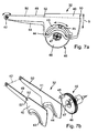
- FIG. 4 another example of the light module 23 is shown.
- the module 23 is very similar to that in FIG. 3 shown module. Corresponding components have been designated by the same reference numerals.
- the module 23 off FIG. 4 is different from the one in FIG. 3 shown in particular by the design and operation of the shutter assembly 32 '.
- the diaphragm arrangement 32 ' is designed as a free-form roller, on whose lateral surface different upper edges 36' are formed with different contour curves.
- the roller is rotatable about a transverse to the optical axis 33 of the light module 23 and approximately horizontally extending axis of rotation 38.
- an actuator 39 comprising an electric motor 39', in particular a stepper motor, driven by this worm 39 "and a driven by the worm gear 39"', which rotatably with the roller 32' is in communication .
- an electric motor 39' in particular a stepper motor
- the diaphragm arrangement 32 ' By turning the diaphragm arrangement 32 ', one of the upper edges 36' can be moved as an effective upper edge into the beam path of the module 23.
- the effective upper edge 36 ' is then projected by the projection lens 34 as a light-dark boundary on the road ahead of the motor vehicle.
- the reference numeral 32 " is in FIG. 4 a symbolic representation of the freeform roller 32 'to illustrate their operation reproduced.
- four different diaphragm elements with upper edges 36" are arranged with different contour curves.
- the individual diaphragm elements or their upper edges 36 '' are circumferentially spaced approximately 90 ° from each other
- the upper edges 36 '' of the symbolic representation of the roller 32 ' all have a horizontal course, with which a symmetrical light-dark boundary could be created
- Such an embodiment of a freeform roller 32 " is, for example, in FIG. 6 shown.
- the individual panel elements are designated by the reference numeral 60. These may - in deviation from the illustrated embodiment - also be an integral part of the roller body 61. They have upper edges 36 'with different contour curves.
- This in FIG. 6 Downwardly facing diaphragm element 60 is used to produce a conventional low-beam asymmetrical light distribution, as is customary in Europe. Therefore, the lower panel member has a horizontal portion on the left side and on the right side at an angle of about 15 ° sloping portion.
- the upward-facing diaphragm element 60 is in the beam path of the light module 23 from FIG. 4 arranged and therefore forms the so-called. Effective upper edge 36 '.
- the Top edge 36 'of the upper aperture element 60 is for generating the in FIG.
- FIG. 5 A third embodiment of a light module 23 is shown in FIG FIG. 5 in a view from the front, that is opposite to the light exit direction 20 shown.
- This module 23 comprises a combination of reflection and projection module.
- As light sources LEDs 70, 71 are used. These are arranged on a heat sink 72.
- first LEDs 70 are arranged on the top and the bottom of the heat sink 72 .
- the light emitted by these light is reflected by primary optics in the form of half-shell reflectors 73 in the light exit direction 20.
- the LEDs 70 and the reflectors 73 form a reflection module of the light module 23.
- the reflection module can produce a broad base light distribution that is similar or equal to the light distribution generated by the second light module 24 of the headlight 2.
- LEDs 71 are arranged on the front of the heat sink 72 .
- the light emitted by these light is focused by a primary optics in the form of intent optics 74 of a transparent material with total reflective properties.
- the collimated light is from a secondary optics in the form of a projection lens 75 in Light exit direction 20 projected.
- the LEDs 71, the front optics 74 and the lens 75 form a projection module of the light module 23.
- the projection module can generate a spot light distribution. A superimposition of the basic light distribution of the reflection module and the spotlight distribution results in the desired resulting light distribution of the module 23.
- a diaphragm arrangement for realizing an effective upper edge is provided, which is suitable for producing a dimmed light distribution 10 with symmetrical or asymmetric light-dark boundary 13 with a light-dark boundary 13 arranged above the illuminated area 14.
- the entire module 23 or parts thereof, for example, the projection lens 75 can be pivoted about the vertical axis of rotation 37, so that the illuminated area 14 can be pivoted in the horizontal direction and can be targeted to objects detected in front of the vehicle 1.
- the diaphragm arrangement is designed such that it can generate at least conventional asymmetrical dipped beam, high street lighting, high beam and a partial high beam distribution 80 on its own traffic side. In addition, it can still generate highway or city light.
- the dimmed light distribution 10 with the above the light-dark boundary 13 arranged illuminated area 14 is not generated by the headlight 3.
Landscapes
- Engineering & Computer Science (AREA)
- General Engineering & Computer Science (AREA)
- Mechanical Engineering (AREA)
- Non-Portable Lighting Devices Or Systems Thereof (AREA)
- Lighting Device Outwards From Vehicle And Optical Signal (AREA)
Description
Die vorliegende Erfindung betrifft ein Lichtmodul für einen Kraftfahrzeugscheinwerfer zur Erzeugung einer adaptiven Lichtverteilung, wie aus dem gattungsgemäßen Dokument
Die Erfindung betrifft außerdem einen Kraftfahrzeugscheinwerfer mit einem Lichtmodul der genannten Art.The invention also relates to a motor vehicle headlight with a light module of the type mentioned.
Schließlich betrifft die vorliegende Erfindung auch ein Scheinwerfersystem für ein Kraftfahrzeug zur Ausleuchtung einer Fahrbahn vor dem Kraftfahrzeug mit einer adaptiven Lichtverteilung. Das Scheinwerfersystem umfasst am Bug des Fahrzeugs jeweils mindestens einen Kraftfahrzeugscheinwerfer auf der eigenen Verkehrsseite und auf der Gegenverkehrsseite, Mittel zum Erfassen eines Abbilds eines Bereichs vor dem Fahrzeug und Mittel zum Auswerten des erfassten Abbilds zur Detektion von Objekten vor dem Fahrzeug. Zumindest einer der Scheinwerfer weist mindestens ein Lichtmodul zur Erzeugung einer adaptiven Lichtverteilung der eingangs genannten Art auf.Finally, the present invention also relates to a headlamp system for a motor vehicle for illuminating a roadway in front of the motor vehicle with an adaptive light distribution. The headlamp system comprises at the front of the vehicle at least one vehicle headlight on its own traffic side and on the oncoming traffic side, means for detecting an image of an area in front of the vehicle and means for evaluating the detected image for detecting objects in front of the vehicle. At least one of the headlights has at least one light module for generating an adaptive light distribution of the aforementioned type.
Ein Lichtmodul der eingangs genannten Art ist beispielsweise aus der
Die Verkehrssituation und die Umweltbedingungen in der Umgebung des Fahrzeugs können mittels geeigneter Sensoren erfasst werden. Zum Erfassen der Verkehrsbedingungen, insbesondere des vor dem Fahrzeug befindlichen Verkehrsaufkommens, können Kameras (für sichtbares Licht, IR- oder UV-Strahlung), Radarsensoren, Ultraschallsensoren oder andere geeignete Sensoren eingesetzt werden. Die von diesen Sensoren erfassten Abbilder des Bereichs vor dem Fahrzeug werden durch eine Rechnereinheit anhand geeigneter Algorithmen ausgewertet und zur Steuerung der Blendenanordnung und damit letztlich zur Generierung einer adaptiven Lichtverteilung vor dem Fahrzeug herangezogen. Die Umweltbedingungen können anhand von Regen- oder Schneesensoren, Lichtsensoren, eines Thermometers und anderer geeigneter Sensoren erfasst werden. Auch ein kombinierter Einsatz mehrerer unterschiedlicher Sensoren zum Erfassen der Verkehrs- und Umweltbedingung ist denkbar.The traffic situation and the environmental conditions in the vicinity of the vehicle can be detected by means of suitable sensors. Cameras (for visible light, IR or UV radiation), radar sensors, ultrasonic sensors or other suitable sensors can be used to detect the traffic conditions, in particular the traffic ahead of the vehicle. The images of the area in front of the vehicle detected by these sensors are evaluated by a computer unit using suitable algorithms and used to control the diaphragm arrangement and thus ultimately to generate an adaptive light distribution in front of the vehicle. Environmental conditions may be detected by rain or snow sensors, light sensors, a thermometer and other suitable sensors. A combined use of several different sensors for detecting the traffic and environmental conditions is conceivable.
Ein anderes Lichtmodul der eingangs genannten Art ist aus der
Die beschriebenen Lichtmodule zur Erzeugung einer adaptiven Lichtverteilung bieten bereits einen gegenüber herkömmlichen Lichtmodulen, die lediglich eine Lichtfunktion (z.B. Abblendlicht, Fernlicht oder Nebellicht) erzeugen oder zwischen verschiedenen Lichtfunktionen umgeschaltet werden konnten, erheblichen Sicherheitsgewinn, da eine Vielzahl unterschiedlicher Lichtfunktionen zur Verfügung steht und für die jeweilige Verkehrs- und Umweltsituation die optimale Lichtverteilung ausgewählt werden kann. Dadurch verbessern sich die Sichtverhältnisse für den Fahrer erheblich, ohne dass eine Blendung anderer Verkehrsteilnehmer, die zu einer Beeinträchtigung der Verkehrssicherheit führen würde, zu befürchten wäre. Dennoch haben die bekannten Lichtmodule noch Potential hinsichtlich einer Verbesserung der Sichtverhältnisse des Fahrers, ohne jedoch zu einer Blendung der anderen Verkehrsteilnehmer zu führen.
Der vorliegenden Erfindung liegt deshalb die Aufgabe zugrunde, eine einfache und kostengünstige Möglichkeit zu schaffen, die Sichtverhältnisse des Fahrers eines Kraftfahrzeugs, insbesondere hinsichtlich potentiell verkehrsgefährdender Objekte im Bereich vor dem Kraftfahrzeug, zu verbessern, ohne jedoch zu einer Blendung anderer Verkehrsteilnehmer zu führen.The light modules described for generating an adaptive light distribution already offer a considerable gain in safety over conventional light modules which only produce a light function (eg dipped beam, high beam or fog light) or can be switched between different light functions, since a multiplicity of different light functions are available and for the respective traffic and environmental situation the optimal light distribution can be selected. As a result, the visibility conditions for the driver improve significantly, without dazzling other road users, which would lead to a reduction in traffic safety would be feared. Nevertheless, the known light modules still have potential in terms of improving the driver's visibility, but without leading to dazzling the other road users.
The present invention is therefore based on the object to provide a simple and cost-effective way to improve the visibility of the driver of a motor vehicle, especially with regard to potentially traffic-endangering objects in the area in front of the motor vehicle, but without leading to dazzling other road users.
Zur Lösung dieser Aufgabe wird ein Lichtmodul mit den Merkmalen von Anspruch 1 vorgeschlagen.To solve this problem, a light module with the features of
Bei der durch das erfindungsgemäße Lichtmodul erzeugten Lichtverteilung wird also oberhalb der horizontalen Hell-Dunkel-Grenze lediglich ein insbesondere hinsichtlich seiner Erstreckung in horizontaler Richtung sehr begrenzter Bereich ausgeleuchtet. Das hat erhebliche Vorteile gegenüber der an sich bekannten Teilfernlichtverteilung, bei der oberhalb einer horizontalen Hell-Dunkel-Grenze praktisch der gesamte Bereich auf der eigenen Verkehrsseite oder alternativ auf der Gegenverkehrsseite mit einer Fernlichtverteilung ausgeleuchtet wird. Dieser oberhalb der Hell-Dunkel-Grenze angeordnete ausgeleuchtete Bereich kann in horizontaler Richtung beispielsweise derart positioniert sein, dass er den Fahrbahnrand auf der eigenen Verkehrsseite stärker ausleuchtet. Auf diese Weise kann beispielsweise, wenn durch geeignete Sensoren ein potentiell verkehrsgefährdendes Objekt in Form einer Person oder eines Gegenstands am Fahrbahnrand detektiert wird, die abgeblendete Lichtverteilung mit der horizontalen Hell-Dunkel-Grenze und dem oberhalb der Hell-Dunkel-Grenze ausgebildeten ausgeleuchteten Bereich zumindest kurzzeitig aktiviert werden, um mit dem oberhalb der Helldunkelgrenze angeordneten Bereich das detektierte Objekt anzuleuchten. Die Aufmerksamkeit des Fahrers wird dadurch auf das detektierte Objekt gerichtet. Der Fahrer kann dem detektierten und angestrahlten Objekt ausweichen, die Fahrzeuggeschwindigkeit reduzieren oder andere geeignete Maßnahmen zur Vermeidung einer Kollision mit dem Objekt und/ oder einer Gefährdung des Objekts treffen. Durch die vorliegende Erfindung kann also ein erheblicher Sicherheitsgewinn sowohl für den Fahrer als auch für die detektierten Objekte erzielt werden. Gleichzeitig wird eine Blendung vorausfahrender oder entgegenkommender Verkehrsteilnehmer weitgehend vermieden, da die Erstreckung des oberhalb der Hell-Dunkel-Grenze ausgebildeten ausgeleuchteten Bereichs in horizontaler Richtung nur wenige Winkelgrad beträgt und in der Regel nur für relativ kurze Zeit aktiviert wird.In the case of the light distribution generated by the light module according to the invention, therefore, above the horizontal light-dark boundary only one area, which is very limited in particular in terms of its extent in the horizontal direction, is illuminated. This has considerable advantages over the known split-beam distribution, in which above a horizontal light-dark boundary practically the entire area on the own traffic side or alternatively on the oncoming traffic side is illuminated with a high beam distribution. This illuminated area, which is arranged above the cut-off line, can be positioned in the horizontal direction, for example, in such a way that it illuminates the roadway edge more strongly on its own traffic side. In this way, for example, if a potentially traffic-endangering object in the form of a person or an object is detected at the edge of the road by suitable sensors, the dimmed light distribution with the horizontal light-dark boundary and the illuminated area formed above the light-dark boundary at least be activated briefly to illuminate the detected object with the area arranged above the light-dark boundary. The attention of the driver is thereby directed to the detected object. The driver can avoid the detected and illuminated object, reduce the vehicle speed or take other suitable measures for avoiding a collision with the object and / or endangering the object. By the present invention, therefore, a significant gain in security for both the driver and the detected objects can be achieved. At the same time, dazzling becomes more anticipatory or more responsive Road users largely avoided because the extension of the light-dark boundary formed above the illuminated area in the horizontal direction is only a few degrees and is usually activated only for a relatively short time.
Die horizontale Position des oberhalb der Helldunkelgrenze angeordneten ausgeleuchteten Bereichs der Lichtverteilung kann variiert werden. Dadurch kann der ausgeleuchtete Bereich immer genau auf das detektierte Objekt gerichtet werden und das Objekt deutlich anstrahlen, damit es für den Fahrer unmittelbar erkennbar und identifizierbar ist. Dies ist wichtig, da die vom Fahrer zu wählende Maßnahme zur Vermeidung einer Kollision mit dem Objekt oder einer Gefährdung des Objekts in erster Linie von der Art des Objekts abhängen wird. Bspw. bei spielenden Kindern oder Tieren wird die Wahl der Maßnahme anders ausfallen als bspw. bei Gegenständen.The horizontal position of the illuminated area of the light distribution arranged above the light-dark boundary can be varied. As a result, the illuminated area can always be aimed precisely at the detected object and illuminate the object clearly, so that it is immediately recognizable and identifiable by the driver. This is important because the action to be taken by the driver to avoid a collision with the object or endangering the object will depend primarily on the nature of the object. For example. in playing children or animals, the choice of action will be different than, for example, in the case of objects.
Erfindungsgemäß wird vorgeschlagen, dass das Lichtmodul Mittel zum horizontalen Verschwenken des Lichtmoduls oder eines Teils davon umfasst, um den ausgeleuchteten Bereich oberhalb der horizontalen Hell-Dunkel-Grenze gezielt auf vor dem Fahrzeug detektierte Objekte zu richten. Auf diese Weise kann der ausgeleuchtete Bereich in horizontaler Richtung gezielt an eine Position bewegt werden, wo potentiell verkehrsgefährdende Objekte, beispielsweise Personen oder Tiere, die vor dem Fahrzeug die Fahrbahn überqueren, detektiert wurden. Durch die geringe Erstreckung des ausgeleuchteten Bereichs in horizontaler Richtung von lediglich einigen Winkelgrad kann das detektierte Objekt gezielt angestrahlt werden, ohne dass vorausfahrende und/oder entgegenkommende Verkehrsteilnehmer geblendet werden.According to the invention, it is proposed that the light module comprises means for horizontally pivoting the light module or a part thereof in order to direct the illuminated area above the horizontal light-dark boundary to objects detected in front of the vehicle. In this way, the illuminated area in the horizontal direction can be selectively moved to a position where potentially traffic-endangering objects, such as persons or animals, which cross the roadway in front of the vehicle, have been detected. Due to the small extent of the illuminated area in the horizontal direction of only a few angular degrees, the detected object can be selectively illuminated without dawning and / or oncoming traffic participants are dazzled.
Das Lichtmodul weist eine Sekundäroptik auf, vorzugsweise in Form einer Projektionslinse, zur Abbildung des an der wirksamen Oberkante der Blendenanordnung vorbeigelangten Lichts auf einer Fahrbahn vor dem Fahrzeug. Die Sekundäroptik bildet die wirksame Oberkante der Blendenanordnung als Hell-Dunkel-Grenze der Lichtverteilung auf der Fahrbahn ab. In diesem Fall wäre das Lichtmodul also als ein sogenanntes Projektionsmodul ausgebildet. Zur Erfüllung des Helligkeitsverlaufs der Helldunkelgrenze oder zur Beseitigung von Farbeffekten an der Helldunkelgrenze ist die Projektionslinse vorzugsweise mit regelmäßigen oder unregelmäßigen Mikrostrukturen versehen, die eine Höhe von etwa 3-30 µm zur Basisfläche der Linse aufweisen. Die Oberfläche der Linse ist bevorzugt plan-konvex oder meniskusförmig.
Gemäß einer vorteilhaften Weiterbildung der vorliegenden Erfindung wird vorgeschlagen, dass der ausgeleuchtete Bereich oberhalb der horizontalen Hell-Dunkel-Grenze eine Erstreckung von etwa 2° horizontal und etwa 3° bis 5° vertikal aufweist. Die Breite des ausgeleuchteten Bereichs wird von einer in etwa vertikal verlaufenden seitlichen Hell-Dunkel-Grenze zur gegenüberliegenden in etwa vertikal verlaufenden seitlichen Hell-Dunkel-Grenze gemessen. Die Höhe des ausgeleuchteten Bereichs wird ausgehend von der horizontalen Hell-Dunkel-Grenze nach oben bis zum oberen Ende des ausgeleuchteten Bereichs gemessen. Selbstverständlich kann der ausgeleuchtete Bereich, insbesondere in vertikaler Richtung, eine Erstreckung von deutlich mehr als 3° aufweisen, was zur Ausleuchtung von Objekten weit oberhalb der Fahrbahn, beispielsweise von Personen auf einer Autobahnbrücke, vorteilhaft ist. Auch die Erstreckung in horizontaler Richtung kann in bestimmten Situationen deutlich mehr als 2° betragen. So ist es beispielsweise denkbar, wenn der ausgeleuchtete Bereich oberhalb der horizontalen Hell-Dunkel-Grenze in horizontaler Richtung derart positioniert ist, dass er den Fahrbahnrand auf der eigenen Verkehrsseite ausleuchtet, dass sich der ausgeleuchtete Bereich relativ weit in Richtung der eigenen Verkehrsseite über den Fahrbahnrand hinaus nach außen erstreckt. Es ist denkbar, dass die Breite und die Höhe des ausgeleuchteten Bereichs oberhalb der Helldunkelgrenze während des bestimmungsgemäßen Betriebs des Lichtmoduls variabel ist. Vorzugsweise ist jedoch die Breite und die Höhe des ausgeleuchteten Bereichs oberhalb der Helldunkelgrenze feststehend und wird während des Betriebs des Lichtmoduls nicht variiert.The light module has a secondary optics, preferably in the form of a projection lens, for imaging the light passed by the effective upper edge of the diaphragm arrangement on a roadway in front of the vehicle. The secondary optics depicts the effective upper edge of the diaphragm arrangement as a light-dark boundary of the light distribution on the roadway. In this case, the light module would be as a so-called projection module educated. To fulfill the brightness curve of the light-dark boundary or to eliminate color effects at the light-dark boundary, the projection lens is preferably provided with regular or irregular microstructures having a height of about 3-30 microns to the base surface of the lens. The surface of the lens is preferably plano-convex or meniscus-shaped.
According to an advantageous development of the present invention, it is proposed that the illuminated area above the horizontal light-dark boundary has an extent of approximately 2 ° horizontally and approximately 3 ° to 5 ° vertically. The width of the illuminated area is measured from an approximately vertical lateral bright-dark boundary to the opposite approximately vertical lateral bright-dark boundary. The height of the illuminated area is from the horizontal light-dark border up to the upper end of the illuminated area measured. Of course, the illuminated area, in particular in the vertical direction, have an extension of significantly more than 3 °, which is advantageous for illuminating objects far above the road, for example, persons on a highway bridge. Also, the extent in the horizontal direction can be significantly more than 2 ° in certain situations. So it is conceivable, for example, if the illuminated area above the horizontal cut-off in the horizontal direction is positioned so that it illuminates the edge of the road on its own side, that the illuminated area relatively far in the direction of its own traffic side on the edge of the road extends outwards. It is conceivable that the width and the height of the illuminated area above the light-dark boundary during the intended operation of the light module is variable. Preferably, however, the width and height of the illuminated area above the light-dark boundary is fixed and does not vary during operation of the light module.
Besonders vorteilhaft ist es, wenn die Mittel zum horizontalen Verschwenken des Lichtmoduls zur Realisierung einer dynamischen Kurvenlichtfunktion des Scheinwerfers vorgesehen sind. In diesem Fall könnten zum Verschwenken des ausgeleuchteten Bereichs oberhalb der horizontalen Hell-Dunkel-Grenze Mittel verwendet werden, die eigentlich zu einem anderen Zweck sowieso in dem Lichtmodul beziehungsweise dem Scheinwerfer vorhanden sind. Auf zusätzliche mechanische Bauteile (Aktoren, Getriebe, Koppelelemente etc.) zur Realisierung einer Verschwenkbewegung des oberhalb der Hell-Dunkel-Grenze angeordneten ausgeleuchteten Bereichs in horizontaler Richtung kann somit verzichtet werden.It is particularly advantageous if the means for horizontal pivoting of the light module are provided for realizing a dynamic cornering function of the headlamp. In this case, means could be used for pivoting the illuminated area above the horizontal light-dark boundary, which are actually present anyway for another purpose in the light module or the headlight. On additional mechanical components (actuators, gearbox, coupling elements, etc.) for realizing a pivoting movement of the above the light-dark boundary arranged illuminated area in the horizontal direction can thus be dispensed with.
Gemäß einer bevorzugten Ausführungsform der vorliegenden Erfindung wird vorgeschlagen, dass die Blendenanordnung als eine um eine quer zur optischen Achse verlaufende, horizontale Drehachse drehbare Freiformwalze ausgebildet ist, auf deren Mantelfläche mehrere quer zur optischen Achse verlaufende und zueinander in Umfangsrichtung beabstandete Oberkanten mit unterschiedlichen Konturverläufen ausgebildet sind, wobei eine der Oberkanten die wirksame Oberkante der Blendenanordnung zur Erzeugung der abgeblendeten Lichtverteilung mit oberhalb der Hell-Dunkel-Grenze vorgesehenem ausgeleuchtetem Bereich bildet. Die Oberkante zur Erzeugung der abgeblendeten Lichtverteilung mit oberhalb der Hell-Dunkel-Grenze vorgesehenem ausgeleuchtetem Bereich weist im Wesentlichen den gleichen Verlauf wie eine Oberkante auf, die zur Erzeugung einer Lichtverteilung mit horizontaler Hell-Dunkel-Grenze (z.B. Abblendlicht, Nebellicht o.ä.) dient. Zusätzlich ist jedoch in der Oberkante ein Schlitz vorgesehen, der zur Erzeugung des ausgeleuchteten Bereichs der Lichtverteilung oberhalb der Hell-Dunkel-Grenze dient.According to a preferred embodiment of the present invention, it is proposed that the diaphragm arrangement is designed as a free-form roller rotatable about a horizontal axis of rotation running transversely to the optical axis, on the lateral surface of which a plurality of upper edges running transversely to the optical axis and spaced apart in the circumferential direction are formed with different contour profiles wherein one of the upper edges forms the effective upper edge of the diaphragm arrangement for producing the dimmed light distribution with the illuminated area provided above the cut-off line. The upper edge for generating the dimmed light distribution with the illuminated area provided above the cut-off line has substantially the same shape as an upper edge, which is used to generate a light distribution with a horizontal light-dark boundary (eg dipped beam, fog light, etc.). ) serves. In addition, however, a slot is provided in the upper edge, which serves to generate the illuminated area of the light distribution above the cut-off line.
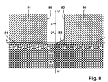
Die horizontale Hell-Dunkel-Grenze kann symmetrisch ausgebildet sind, das heißt die gesamte Hell-Dunkel-Grenze erstreckt sich auf dem vor dem Fahrzeug angeordneten Messschirm geringfügig (etwa -1°) unterhalb der Vertikalen VV. Die horizontale Hell-Dunkel-Grenze kann aber auch asymmetrisch ausgebildet sein, mit einem horizontalen Abschnitt auf der Gegenverkehrsseite und einem demgegenüber höheren Abschnitt auf der eigenen Verkehrsseite. Der Übergang von dem niedrigeren Abschnitt der Hell-Dunkel-Grenze auf der Gegenverkehrsseite zu dem höheren Abschnitt auf der eigenen Verkehrsseite kann entweder stufenförmig oder auf andere Weise, beispielsweise durch einen schrägen Anstieg, insbesondere einen 15°-Anstieg, erfolgen.The horizontal cut-off line can be symmetrical, that is to say the entire cut-off line extends slightly (approximately -1 °) below the vertical VV on the screen located in front of the vehicle. However, the horizontal cut-off line can also be formed asymmetrically, with a horizontal section on the oncoming traffic side and a contrast higher section on the own traffic side. The transition from the lower portion of the cut-off line on the oncoming traffic side to the higher portion on the own traffic side may be either stepped or in another way, for example by an oblique increase, in particular a 15 ° increase done.
In den Freiformwalzen ist der Platz auf der Mantelfläche zur Anordnung der verschiedenen Oberkanten mit unterschiedlichen Konturverläufen beschränkt. Der Abstand in Umfangsrichtung von auf der Mantelfläche aufgebrachten benachbarten Oberkanten muss so groß sein, dass sich benachbarte Oberkanten bei der Erzeugung der gewünschten Lichtverteilung nicht stören. Deshalb können bei einer derart ausgestalteten Blendenanordnung nur eine beschränkte Anzahl an unterschiedlichen Oberkanten auf der Mantelfläche der Walze angeordnet sein. Zur Realisierung der Lichtverteilung mit oberhalb der Hell-Dunkel-Grenze angeordnetem ausgeleuchtetem Bereich wird deshalb vorgeschlagen, die entsprechende Oberkante anstelle einer anderen Oberkante auf der Mantelfläche der Walze anzuordnen. Vorzugsweise wird eine andere Oberkante ersetzt, die zur Erzeugung einer Lichtverteilung dient, die in der Praxis nur selten aktiviert wird. Eine solche Lichtverteilung ist beispielsweise das Teilfernlicht auf der Gegenverkehrsseite. Dieses wird von dem im Bug des Fahrzeugs auf der Gegenverkehrsseite angeordneten Scheinwerfer beziehungsweise einem Lichtmodul dieses Scheinwerfers erzeugt. Der im Bug des Fahrzeugs auf der eigenen Verkehrsseite angeordnete Scheinwerfer bildet das entsprechende Teilfernlicht für die eigene Verkehrsseite. Bei einem vereinfachten Scheinwerfersystem kann lediglich einer der Scheinwerfer des Systems, beispielsweise der auf der Gegenverkehrsseite angeordnete Scheinwerfer, die abgeblendete Lichtverteilung mit oberhalb der Hell-Dunkel-Grenze vorgesehenem ausgeleuchtetem Bereich erzeugen. Selbstverständlich kann bei dem vereinfachten System auch lediglich der auf der eigenen Verkehrsseite angeordnete Scheinwerfer zur Erzeugung der abgeblendeten Lichtverteilung mit oberhalb der Hell-Dunkel-Grenze vorgesehenem ausgeleuchtetem Bereich ausgebildet sein.In the freeform rollers, the space on the lateral surface is limited to the arrangement of the various upper edges with different contour curves. The spacing in the circumferential direction of adjacent upper edges applied on the lateral surface must be so large that adjacent upper edges do not interfere with the generation of the desired light distribution. Therefore, only a limited number of different upper edges can be arranged on the lateral surface of the roller in a diaphragm arrangement designed in this way. In order to realize the light distribution with the illuminated area arranged above the cut-off line, it is therefore proposed to arrange the corresponding upper edge instead of another upper edge on the outer surface of the roller. Preferably, another top edge is replaced, which serves to generate a light distribution, which is rarely activated in practice. Such a light distribution is for example the Teilfernlicht on the opposite side. This is generated by the arranged in the bow of the vehicle on the opposite side of the headlight or a light module of this headlight. The spotlight, which is located in the bow of the vehicle on its own traffic side, forms the corresponding partial high beam for its own traffic side. In a simplified headlamp system, only one of the headlamps of the system, for example, the arranged on the opposite side headlights, the dimmed light distribution provided above the cut-off light and illuminated area produce. Of course, in the simplified system, only the arranged on the own traffic side headlamps for generating the dimmed light distribution with above the light-dark boundary provided illuminated area may be formed.
Alternativ wird vorgeschlagen, dass die Blendenanordnung mehrere im Wesentlichen quer zur optischen Achse des Lichtmoduls verlaufende und um eine parallel zur optischen Achse angeordnete horizontale Drehachse relativ zueinander bewegbare Blendenelemente aufweist, wobei eine der Oberkanten oder mehrere Oberkanten durch Überlagerung die im Strahlengang angeordnete wirksame Oberkante zur Erzeugung der abgeblendeten Lichtverteilung mit oberhalb der Hell-Dunkel-Grenze vorgesehenem ausgeleuchtetem Bereich bilden. Die wirksame Oberkante ist dabei ähnlich wie eine Oberkante zur Erzeugung einer herkömmlichen abgeblendeten Lichtverteilung mit Helldunkelgrenze ausgebildet, wobei sie im Unterschied zu der Oberkante zur Erzeugung der herkömmlichen abgeblendeten Lichtverteilung einen Schlitz aufweist. Damit die wirksame Oberkante die genannte Kontur aufweist, ist eine Oberkante entweder eines einzigen oder mehrerer Blendenelemente mit einem Schlitz versehen.Alternatively, it is proposed that the diaphragm arrangement has a plurality of diaphragm elements extending essentially transversely to the optical axis of the light module and disposed about a horizontal axis parallel to the optical axis. One of the upper edges or several upper edges generates the effective upper edge arranged in the beam path by superposition form the dimmed light distribution with above the light-dark boundary provided illuminated area. The effective upper edge is similar to an upper edge designed to produce a conventional dimmed light distribution with light-dark boundary, wherein it has a slot in contrast to the upper edge to produce the conventional dimmed light distribution. In order for the effective upper edge to have said contour, an upper edge of either a single or multiple aperture elements is provided with a slot.
Das Lichtmodul kann eine beliebige Lichtquelle aufweisen. Denkbar ist bspw. eine herkömmliche Glühlampe, eine Gasentladungslampe, oder eine Lichtauskoppelfläche eines Lichtleiters. Gemäß einer bevorzugten Ausführungsform wird vorgeschlagen, dass die mindestens eine Lichtquelle eine oder mehrere Halbleiterlichtquellen (LEDs) umfasst.The light module can have any desired light source. It is conceivable, for example, a conventional incandescent lamp, a gas discharge lamp, or a light output surface of a light guide. According to a preferred embodiment, it is proposed that the at least one light source comprises one or more semiconductor light sources (LEDs).
Die Primäroptik kann bspw. einen Reflektor umfassen. Gemäß einem Ausführungsbeispiel der Erfindung wird jedoch vorgeschlagen, dass die mindestens eine Primäroptik ein oder mehrere optisch wirksame Elemente aus einem transparenten Material aufweist, die das ausgesandte Licht mittels Totalreflexion bündeln. Diese optisch wirksamen Elemente arbeiten ähnlich wie Lichtwellenleiter nach dem Prinzip der Totalreflexion und ermöglichen eine Bündelung des von den Lichtquellen ausgesandten Lichts auf besonders effiziente Weise, insbesondere mit besonders geringen Reflexionsverlusten. Der Einsatz solcher optisch wirksamer Elemente ist insbesondere in Verbindung mit dem Einsatz von Halbleiterlichtquellen vorteilhaft. Dabei ist es denkbar, dass jeder Halbleiterlichtquelle ein eigenes optisches Element zugeordnet ist. Lichtquellen und optische Elemente können in sog. Arrays angeordnet sein. Zur Lösung der der vorliegenden Erfindung zugrundeliegenden Aufgabe wird des Weiteren ein Kraftfahrzeugscheinwerfer vorgeschlagen, der mindestens ein erfindungsgemäßes Lichtmodul aufweist. Besonders bevorzugt ist, wenn bei dem Kraftfahrzeugscheinwerfer das Lichtmodul nach einem der Ansprüche 2 bis 8 ausgebildet ist.The primary optics may, for example, comprise a reflector. According to one embodiment of the invention, however, it is proposed that the at least one primary optic has one or more optically active elements made of a transparent material, which concentrate the emitted light by means of total reflection. These optically active elements work similar to optical waveguides according to the principle of total reflection and allow bundling of the light emitted by the light sources in a particularly efficient manner, in particular with particularly low reflection losses. The use of such optically active elements is particularly advantageous in connection with the use of semiconductor light sources. It is conceivable that each semiconductor light source is assigned its own optical element. Light sources and optical elements can be arranged in so-called arrays. To solve the object underlying the present invention, a motor vehicle headlamp is furthermore proposed which has at least one light module according to the invention. It is particularly preferred if in the motor vehicle headlight, the light module is designed according to one of
Falls der Kraftfahrzeugscheinwerfer mehrere Lichtmodule aufweist, die eine Grundlichtverteilung und eine Spotlichtverteilung erzeugen, die beide zur Realisierung der abgeblendeten Lichtverteilung überlagert werden, ist es besonders vorteilhaft, wenn das erfindungsgemäß ausgebildete Lichtmodul zur Realisierung der Spotlichtfunktion ausgebildet ist. Das Grundlichtmodul leuchtet den Bereich vor dem Fahrzeug besonders breit aus. Die Grundlichtverteilung weist eine Hell-Dunkel-Grenze, vorzugsweise eine symmetrische Hell-Dunkel-Grenze auf. Zur Erzeugung der abgeblendeten Lichtverteilung wird der Grundlichtverteilung die Spotlichtverteilung überlagert. Auch die Spotlichtverteilung weist vorzugsweise eine Hell-Dunkel-Grenze (symmetrisch oder asymmetrisch) auf. Zur Realisierung einer Kurvenlichtfunktion des Scheinwerfers ist lediglich das Spotlichtmodul in horizontaler Richtung bewegbar. Zur Variation der horizontalen Position des oberhalb der Hell-Dunkel-Grenze vorgesehenen ausgeleuchteten Bereichs der Lichtverteilung kann das Spotlichtmodul in horizontaler Richtung verschwenkt werden. Dadurch wird die abgeblendete Spotlichtverteilung zusammen mit dem oberhalb der Hell-Dunkel-Grenze angeordneten ausgeleuchteten Bereich relativ zur Grundlichtverteilung in horizontaler Richtung bewegt und gezielt auf ein detektiertes Objekt auf, oberhalb oder neben der Fahrbahn gerichtet.If the motor vehicle headlight has a plurality of light modules which generate a basic light distribution and a spot light distribution, which are both superimposed to realize the dimmed light distribution, it is particularly advantageous if the light module designed according to the invention is designed to realize the spotlight function. The basic lighting module illuminates the area in front of the vehicle particularly wide out. The basic light distribution has a light-dark boundary, preferably a symmetrical light-dark boundary. To generate the dimmed light distribution of the basic light distribution is superimposed on the spotlight distribution. The spotlight distribution also preferably has a light-dark boundary (symmetrical or asymmetrical). To realize a cornering light function of the headlamp, only the spotlight module is movable in the horizontal direction. In order to vary the horizontal position of the illuminated area of the light distribution provided above the cut-off line, the spotlight module can be pivoted in the horizontal direction. As a result, the dimmed spotlight distribution, together with the illuminated area arranged above the light-dark boundary, is moved in the horizontal direction relative to the basic light distribution and directed specifically to a detected object on, above or next to the roadway.
Als eine weitere Lösung der Aufgabe der vorliegenden Erfindung wird ausgehend von dem Scheinwerfersystem der eingangs genannten Art vorgeschlagen, bei dem mindestens ein Lichtmodul von mindestens einem der Scheinwerfer in der erfindungsgemäßen Weise ausgebildet ist. Besonders bevorzugt ist, wenn bei dem Scheinwerfersystem das Lichtmodul nach einem der Ansprüche 2 bis 9 ausgebildet ist.As a further solution of the object of the present invention is proposed starting from the headlight system of the type mentioned, in which at least one light module is formed by at least one of the headlights in the manner according to the invention. It is particularly preferred if in the headlamp system, the light module is designed according to one of
Gemäß einer vorteilhaften Weiterbildung der Erfindung wird vorgeschlagen, dass nur der auf der Gegenverkehrsseite angeordnete Scheinwerfer des Scheinwerfersystems ein in erfindungsgemäßer Weise ausgebildetes Lichtmodul mit einer derart ausgebildeten Oberkante aufweist, dass es die abgeblendete Lichtverteilung mit dem oberhalb der Hell-Dunkel-Grenze vorgesehenen ausgeleuchteten Bereich erzeugen kann.According to an advantageous embodiment of the invention, it is proposed that only arranged on the opposite side of the headlight of the headlamp system in accordance with the invention trained light module having a top edge formed in such a way that it can produce the dimmed light distribution with the above the light-dark boundary provided illuminated area.
Gemäß einer bevorzugten Ausführungsform der vorliegenden Erfindung wird vorgeschlagen, dass das Scheinwerfersystem Mittel zum Erfassen eines Abbilds eines Bereichs vor dem Fahrzeug und Mittel zum Auswerten des erfassten Abbilds zur Detektion von Objekten vor dem Fahrzeug aufweist, wobei die Mittel zum Erfassen des Abbilds eines Bereichs vor dem Fahrzeug als eine Kamera (für sichtbares Licht, IR- oder UV-Strahlen) ausgebildet sind. Selbstverständlich ist es auch denkbar, die Mittel zum Erfassen des Abbilds eines Bereichs vor dem Fahrzeug als Radarsensoren, oder Ultraschallsensoren auszubilden. Es können auch mehrere der genannten oder andere Sensoren gemeinsam zur Detektion von potentiell verkehrsgefährdenden Objekten vor dem Fahrzeug eingesetzt werden. Ebenso ist es denkbar, dass auf bereits im Fahrzeug sowieso schon vorhandene Sensoren zum Erfassen eines Abbilds eines Bereichs vor dem Fahrzeug zurückgegriffen wird. In diesem Fall müssten für die vorliegende Erfindung keine zusätzlichen Sensoren im Kraftfahrzeug vorgesehen werden. Insbesondere ist es vorteilhaft, wenn die Kamera das Abbild durch Empfang und Verarbeitung unsichtbarer IR-Strahlung erfasst und wenn die Kamera Teil eines Nachtsichtsystems des Fahrzeugs ist, welches dem Fahrer des Fahrzeugs das mittels der Kamera erfasste Abbild des Bereichs vor dem Fahrzeug mittels eines Bildschirms oder einer Projektion auf eine Windschutzscheibe des Fahrzeugs oder auf andere Stellen im Fahrzeug präsentiert. Unter Umständen ist das Nachtsichtsystem bereits mit einem System zur Detektion von Objekten vor dem Fahrzeug ausgestattet. Die entsprechenden Signale des Nachtsichtsystems können bspw. von einem Bussystem des Kraftfahrzeugs abgegriffen und zur Steuerung des Lichtmoduls zur Erzeugung der abgeblendeten Lichtverteilung mit dem oberhalb der Helldunkelgrenze angeordneten ausgeleuchteten Bereich herangezogen werden. Das erfindungsgemäße Lichtmodul kann also auf bereits am Fahrzeugbus anliegende Signale zurückgreifen.According to a preferred embodiment of the present invention, it is proposed that the headlamp system comprises means for detecting an image of an area in front of the vehicle and means for evaluating the detected image for detecting objects in front of the vehicle, wherein the means for detecting the image of an area in front of the vehicle Vehicle as a camera (for visible light, IR or UV rays) are formed. Of course, it is also conceivable to form the means for detecting the image of an area in front of the vehicle as radar sensors, or ultrasound sensors. It is also possible to use a plurality of said sensors or other sensors together for the detection of potentially traffic-endangering objects in front of the vehicle. It is likewise conceivable for sensors already existing in the vehicle to be used for detecting an image of an area in front of the vehicle. In this case, no additional sensors would have to be provided in the motor vehicle for the present invention. In particular, it is advantageous if the camera captures the image by receiving and processing invisible IR radiation and if the camera is part of a night vision system of the vehicle, which provides the driver of the vehicle with the captured by the camera image of the area in front of the vehicle by means of a screen or a projection onto a windshield of the vehicle or to other locations in the vehicle presented. Under certain circumstances, the night vision system already equipped with a system for detecting objects in front of the vehicle. The corresponding signals of the night vision system can, for example, be picked up by a bus system of the motor vehicle and used to control the light module for generating the dimmed light distribution with the illuminated area arranged above the light-dark boundary. The light module according to the invention can therefore fall back on already applied to the vehicle bus signals.
Weitere Merkmale und Vorteile der vorliegenden Erfindung werden nachfolgend unter Bezugnahme auf die Figuren näher erläutert. Es zeigen:
Figur 1- ein Kraftfahrzeug mit einem erfindungsgemäßen Scheinwerfersystem gemäß einer bevorzugten Ausführungsform;
Figur 2- ein erfindungsgemäßer Kraftfahrzeugscheinwerfer gemäß einer bevorzugten Ausführungsform;
Figur 3- ein erfindungsgemäßes Lichtmodul gemäß einer ersten bevorzugten Ausführungsform;
Figur 4- ein erfindungsgemäßes Lichtmodul gemäß einer zweiten bevorzugten Ausführungsform;
Figur 5- ein erfindungsgemäßes Lichtmodul gemäß einer dritten bevorzugten Ausführungsform;
Figur 6- eine Blendenanordnung des Lichtmoduls aus
Figur 4 ;
- Figuren 7a und 7b
- eine Blendenanordnung des Lichtmoduls aus
Figur 3 in verschiedenen Ansichten; - Figur 8
- eine, aus dem Stand der Technik bekannte, auf einem in einem Abstand zu einem Kraftfahrzeug angeordneten Messschirm abgebildete Teilfernlichtverteilung; und
- Figur 9
- eine mit einem der erfindungsgemäßen Lichtmodule gemäß der
Figuren 3bis 5
- FIG. 1
- a motor vehicle with a headlamp system according to the invention according to a preferred embodiment;
- FIG. 2
- an inventive motor vehicle headlamp according to a preferred embodiment;
- FIG. 3
- an inventive light module according to a first preferred embodiment;
- FIG. 4
- an inventive light module according to a second preferred embodiment;
- FIG. 5
- an inventive light module according to a third preferred embodiment;
- FIG. 6
- an aperture assembly of the light module
FIG. 4 ;
- FIGS. 7a and 7b
- an aperture assembly of the light module
FIG. 3 in different views; - FIG. 8
- a, known from the prior art, on a arranged at a distance to a motor vehicle measuring screen Teilfernlichtverteilung; and
- FIG. 9
- one with one of the light modules according to the invention according to the
FIGS. 3 to 5 achievable light distribution.
In
Die von dem mindestens einen Lichtmodul des mindestens einen Scheinwerfers 2, 3 erzeugte abgeblendete Lichtverteilung mit dem oberhalb der Helldunkelgrenze angeordneten ausgeleuchteten Bereich ist in
Die Lichtverteilung 10 umfasst eine Grundlichtverteilung, die nach oben durch eine im wesentlichen horizontale Helldunkelgrenze 13 begrenzt wird. In dem dargestellten Ausführungsbeispiel ist die Helldunkelgrenze 13 symmetrisch ausgebildet, das heißt sie hat sowohl auf der eigenen Verkehrsseite als auch auf der Gegenverkehrsseite in etwa den gleichen horizontalen Verlauf. Selbstverständlich könnte die Helldunkelgrenze 13 auch asymmetrisch ausgebildet sein, wobei ein Abschnitt der Helldunkelgrenze 13 auf der eigenen Verkehrsseite dann oberhalb eines Abschnitts auf der Gegenverkehrsseite angeordnet wäre. Der Übergang zwischen den beiden Abschnitten kann stufenartig oder anderweitig, bspw. mittels eines in einem Winkel von 15° ansteigenden Abschnitts, erfolgen. Die dargestellte Grundlichtverteilung erstreckt sich in horizontaler Richtung von etwa -40° bis +40° und in vertikaler Richtung von etwa -13° bis etwa -1°.The
Die Lichtverteilung 10 umfasst außerdem einen oberhalb der Helldunkelgrenze 13 angeordneten ausgeleuchteten Bereich 14, der seitlich zumindest bereichsweise durch annähernd vertikal verlaufende Helldunkelgrenzen begrenzt wird. In dem dargestellten Ausführungsbeispiel verlaufen die seitlichen Helldunkelgrenzen zur Grundlichtverteilung hin im Wesentlichen vertikal und sind nach oben hin nach innen gebogen, so dass der Bereich 14 nach oben hin die Form eines Halbkreises hat. Selbstverständlich kann die Form des Bereichs 14 in der Praxis von der dargestellten Form abweichen. Wichtig ist jedoch, dass der Bereich 14 sowohl in horizontaler als auch in vertikaler Richtung eine Erstreckung von lediglich einigen Grad hat. Die Breite wird dabei von einem Punkt, wo der Gradient der Helligkeitsverteilung einen bestimmten Wert überschreitet, vorzugsweise ein Maximum aufweist, auf der linken Seite des Bereichs 14, zu einem entsprechenden Punkt auf der rechten Seite des Bereichs 14 gemessen. Die genannten Punkte befinden sich üblicherweise am linken Dunkel-Hell-Übergang bzw. am rechten Hell-Dunkel-Übergang des Bereichs 14. In dem dargestellten Ausführungsbeispiel hat der Bereich 14 eine Breite b von etwa 2° und eine Höhe h von etwa 3°. In dem dargestellten Beispiel ist der Bereich 14 oberhalb des Bereichs 12 der Grundlichtverteilung mit der höchsten Beleuchtungsstärke angeordnet. In einem Lichtmodul in horizontaler Nullstellung liegt der Bereich 14 in etwa auf der Vertikalen VV. Aufgrund der Verschwenkung des die Lichtverteilung 10 in
Selbstverständlich kann die Lichtverteilung 10 auch anders ausgebildet sein. So ist es bspw. denkbar, dass der Bereich 12 der größten Beleuchtungsstärke in der horizontalen Nullstellung des Lichtmoduls nicht auf der Vertikalen, sondern seitlich versetzt dazu angeordnet ist. Entsprechendes gilt für den ausgeleuchteten Bereich 14 oberhalb der Helldunkelgrenze 13, der in der horizontalen Nullstellung des Moduls ebenfalls seitlich versetzt zur Vertikalen angeordnet sein könnte.Of course, the
In
In
Ein Beispiel für die Ausgestaltung der Blendenanordnung 32 ist in den
Durch Betätigung des Aktors 46 wird der Führungsstift 45 in den Kulissen 43, 44 bewegt. Da die Drehachsen 42, 47 feststehen, führt eine Bewegung des Stifts 45 in den Kulissen 43, 44 zu einer Verschwenkbewegung 51 der Blendenelemente 40, 41 um die Drehachse 42. Die im Strahlengang angeordnete wirksame Oberkante der gesamten Blendenanordnung 32 ergibt sich aus einer Überlagerung der Oberkanten 49, 50 der beiden Blendenelemente 40, 41. Durch Bewegen des Stifts 45 in den Kulissen 43, 44 kann der Verlauf der wirksamen Oberkante der Blendenanordnung 32 variiert werden. In der in
By actuating the
In der Oberkante 49 des Blendenelements 40 ist ein Schlitz 52 ausgebildet, der zur Erzeugung des oberhalb der Helldunkelgrenze 13 angeordneten ausgeleuchteten Bereichs 14 der Lichtverteilung 10 dient. In dem dargestellten Ausführungsbeispiel wird der Bereich 14 allein durch den Schlitz 52 in der Oberkante 49 erzeugt. Es wäre jedoch auch denkbar, dass der Bereich 14 durch ein Zusammenwirken beider Oberkanten 49, 50 der Blendenelemente 40, 41 erzeugt wird. Durch Anheben des Blendenelements 41 relativ zum Blendenelement 40 könnte bspw. die Oberkante 50 über einen im Wesentlichen horizontalen Bodenabschnitt 52' des Schlitzes 52 hinaus angehoben werden, so dass die Oberkante 50 die Höhe h des ausgeleuchteten Bereichs 14 oberhalb der Helldunkelgrenze 13 bestimmt. Damit ließe sich auch eine dynamische Variation der Höhe h des Bereichs 14 erzielen.In the
Durch Verschwenken des Lichtmoduls 23 oder von Teilen davon um die vertikale Schwenkachse 37 kann der Bereich 14 oberhalb der Helldunkelgrenze 13 der Lichtverteilung 10 in horizontaler Richtung verschwenkt werden. Damit kann der ausgeleuchtete Bereich 14 gezielt auf vor dem Fahrzeug 1 detektierte Objekte gerichtet werden. Die Aufmerksamkeit des Fahrers wird dadurch besonders stark auf die potentiell gefährdenden Objekte gerichtet. Die detektierten Objekte werden also in der real existierenden Umwelt hervorgehoben und nicht auf irgend einer Darstellung (z.B. auf einem Bildschirm) oder Projektion (z.B. auf der Windschutzscheibe oder einem transparenten Körper im Blickfeld des Fahrers) der Umwelt. Der Fahrer kann seine gesamte Aufmerksamkeit stets auf die Fahrbahn vor seinem Fahrzeug 1 richten und muss die Augen nicht abwenden, um auf Bildschirme, Projektionen oder Warnleuchten zu sehen. Durch die vorliegende Erfindung ergibt sich somit ein entscheidender Sicherheitsgewinn für den Fahrer sowie die detektierten Objekte, ohne dass dadurch andere Verkehrsteilnehmer geblendet oder auf andere Weise gefährdet werden.By pivoting the
In
Mit dem Bezugszeichen 32" ist in
In
Ein drittes Ausführungsbeispiel für ein Lichtmodul 23 ist in
Auf der Oberseite und der Unterseite des Kühlkörpers 72 sind erste LEDs 70 angeordnet. Das von diesen ausgesandte Licht wird durch Primäroptiken in Form von Halbschalenreflektoren 73 in Lichtaustrittsrichtung 20 reflektiert. Die LEDs 70 und die Reflektoren 73 bilden ein Reflexionsmodul des Lichtmoduls 23. Das Reflexionsmodul kann eine breite Grundlichtverteilung erzeugen, die ähnlich oder gleich der von dem zweiten Lichtmodul 24 des Scheinwerfers 2 erzeugten Lichtverteilung ist.On the top and the bottom of the
Auf der Vorderseite des Kühlkörpers 72 sind weitere LEDs 71 angeordnet. Das von diesen ausgesandte Licht wird durch eine Primäroptik in Form von Vorsatzoptiken 74 aus einem transparenten Material mit totalreflektierenden Eigenschaften gebündelt. Das gebündelte Licht wird von einer Sekundäroptik in Form einer Projektionslinse 75 in Lichtaustrittsrichtung 20 projiziert. Die LEDs 71, die Vorsatzoptiken 74 und die Linse 75 bilden ein Projektionsmodul des Lichtmoduls 23. Das Projektionsmodul kann eine Spotlichtverteilung erzeugen. Eine Überlagerung der Grundlichtverteilung des Reflexionsmoduls und der Spotlichtverteilung ergeben die gewünschte resultierende Lichtverteilung des Moduls 23.On the front of the
Im Strahlengang des Reflexions- und/oder des Projektionsmoduls ist eine Blendenanordnung zur Realisierung einer wirksamen Oberkante vorgesehen, welche zur Erzeugung einer abgeblendeten Lichtverteilung 10 mit symmetrischer oder asymmetrischer Helldunkelgrenze 13 mit einem oberhalb der Helldunkelgrenze 13 angeordneten ausgeleuchteten Bereich 14 geeignet ist. Das gesamte Modul 23 oder Teile davon, bspw. die Projektionslinse 75, können um die vertikale Drehachse 37 verschwenkt werden, damit der ausgeleuchtete Bereich 14 in horizontaler Richtung verschwenkt und gezielt auf vor dem Fahrzeug 1 detektierte Objekte gerichtet werden kann.In the beam path of the reflection and / or the projection module, a diaphragm arrangement for realizing an effective upper edge is provided, which is suitable for producing a dimmed
Wie man anhand der in
Eine auf einem vor dem Fahrzeug 1 angeordneten Messschirm abgebildete Teilfernlichtverteilung ist beispielhaft in
In entsprechender Weise arbeitet die Teilfernlichtverteilung 84 auf der Gegenverkehrsseite, die von dem anderen auf der Gegenverkehrsseite des Fahrzeugs 1 angeordneten Scheinwerfer 2 erzeugt wird. Die Verteilung 84 wird durch eine horizontale Helldunkelgrenze 85 bei etwa -0,3° in vertikaler Richtung und eine im Wesentlichen vertikale Helldunkelgrenze 86 bei etwa -2° in horizontaler Richtung begrenzt und leuchtet die Gegenverkehrsseite nach Art eines Fernlichts und die eigene Verkehrsseite nach Art eines Abblendlichts aus. Die Teilfernlichtverteilung 84 wird üblicherweise aktiviert, wenn zwar vorausfahrende, aber keine entgegenkommenden Fahrzeuge erkannt wurden. In der Praxis wird die Teilfernlichtverteilung 84 auf der Gegenverkehrsseite seltener aktiviert. Wenn die horizontale Ausrichtung sowie die Breite des Teilfernlichts variiert werden können, kann das Teilfernlicht auch bei vorausfahrenden oder entgegenkommenden Verkehrsteilnehmern aktiviert werden, wobei das Teilfernlicht dann so eingestellt werden muss, dass ein Schattenbereich der Lichtverteilung genau die vorausfahrenden und/oder entgegenkommenden Verkehrsteilnehmer abdeckt.In a corresponding manner, the divided high-
Falls für ein weiteres Blendenelement 60 zur Erzeugung der weiteren Lichtfunktion in Form der abgeblendeten Lichtverteilung 10 mit oberhalb der Helldunkelgrenze 13 angeordnetem ausgeleuchtetem Bereich 14 auf der Mantelfläche des Walzenkörpers 61 kein Platz besteht, kann ein Blendenelement 60 für eine vorhandene Lichtfunktion durch das Blendenelement 60 zur Erzeugung der weiteren Lichtfunktion ersetzt werden. Dabei bietet es sich an, das Blendenelement 60 des Lichtmoduls 23 des Scheinwerfers 2 auf der Gegenverkehrsseite, das zur Realisierung einer wirksamen Oberkante 36' zur Erzeugung der Teilfernlichtverteilung 84 auf der Gegenverkehrsseite ausgebildet ist, durch das Blendenelement 60 zur Erzeugung der abgeblendeten Lichtverteilung 10 mit oberhalb der Helldunkelgrenze 13 angeordnetem ausgeleuchtetem Bereich 14 zu ersetzen.If for another
Entsprechende Platzprobleme können sich auch bei einer Blendenanordnung 32 nach
Das bevorzugte Scheinwerfersystem des Fahrzeugs 1 umfasst also den Scheinwerfer 2 auf der Gegenverkehrsseite, dessen eines Lichtmodul 23 eine Blendenanordnung 32, 32' zur Erzeugung einer adaptiven Lichtverteilung aufweist. Die Blendenanordnung 32, 32' ist derart ausgebildet, dass sie zumindest herkömmliches asymmetrisches Abblendlicht, Landstraßenlicht, Fernlicht und die abgeblendete Lichtverteilung 10 mit dem oberhalb der Helldunkelgrenze 13 angeordneten ausgeleuchteten Bereich 14 erzeugen kann. Zusätzlich kann sie noch Autobahn- oder Stadtlicht erzeugen. Die Teilfernlichtverteilung 84 auf der Gegenverkehrsseite kann der Scheinwerfer 2 also nicht erzeugen. Der Scheinwerfer 3 auf der eigenen Verkehrsseite weist ebenfalls ein Lichtmodul mit einer Blendenanordnung zur Erzeugung einer adaptiven Lichtverteilung auf. Allerdings ist die Blendenanordnung derart ausgebildet, dass sie zumindest herkömmliches asymmetrisches Abblendlicht, Landstraßenlicht, Fernlicht und eine Teilfernlichtverteilung 80 auf der eigenen Verkehrsseite erzeugen kann. Zusätzlich kann sie noch Autobahn- oder Stadtlicht erzeugen. Die abgeblendete Lichtverteilung 10 mit dem oberhalb der Helldunkelgrenze 13 angeordneten ausgeleuchteten Bereich 14 wird von dem Scheinwerfer 3 nicht erzeugt.The preferred headlamp system of the
Selbstverständlich ist es jedoch denkbar, dass beide Scheinwerfer 2, 3 des Fahrzeugs 1 die abgeblendete Lichtverteilung 10 mit dem oberhalb der Helldunkelgrenze 13 angeordneten ausgeleuchteten Bereich 14 erzeugen können.Of course, it is conceivable, however, that both
Claims (14)
- A light module (23) for a motor vehicle headlamp (2) for generating an adaptive light distribution, the light module (23) comprising- at least one light source (30; 70, 71) for emitting light,- at least one primary optical element (31; 73, 74) for bundling the emitted light,- a diaphragm arrangement (32; 32') for implementing a variable effective upper edge (36; 36'), which can be introduced into a beam path of the emitted and/or bundled light, and- a secondary optical element (34; 75), preferably in the form of a projection lens, for imaging the light passing the effective upper edge (36; 36') of the diaphragm arrangement (32; 32') on a roadway in front of the vehicle (1), wherein the diaphragm arrangement (32; 32') is designed to implement an effective upper edge (36; 36') which brings about the generation of a low beam light distribution (10) with a substantially horizontal light-dark boundary (13) and with an illuminated region (14) formed at a specific horizontal position above the light-dark boundary (13), which region is delimited on the right-hand side and on the left-hand side by light-dark boundaries and has an extent in the horizontal and vertical directions of in each case a few angular degrees on a measuring screen arranged at a distance in front of the headlamp (2), characterized in that the light module (23) comprises means for horizontally pivoting the light module (23) or a part (75) thereof, in order to specifically direct the illuminated region (14) above the horizontal light-dark boundary (13) towards objects detected in front of the vehicle (1).
- The light module (23) as claimed in claim 1, wherein the illuminated region (14) is delimited on the right-hand side and on the left-hand side at least partially by vertical light-dark boundaries.
- The light module (23) as claimed in claim 1 or 2, wherein the illuminated region (14) above the horizontal light-dark boundary (13) has an extent of approximately 2° horizontal and approximately 3° to 5° vertical.
- The light module (23) as claimed in one of the proceeding claims, wherein the means for horizontally pivoting the light module (23) are provided for implementing a dynamic cornering light function of the headlamp (2).
- The light module (23) as claimed in one of claims 1 to 4, wherein the diaphragm arrangement (32; 32') has a drum (32'; 61), which is capable of rotating about a horizontal axis of rotation (38) running transversely with respect to the optical axis (33), with a plurality of upper edges (36'), which are spaced apart from one another, run transversely with respect to the optical axis (33) and have different profiles, being formed on the outer surface of said drum, wherein one of the upper edges forms the effective upper edge (36') for generating the low beam light distribution (10) with the illuminated region (14) provided above the light-dark boundary (13).
- The light module (23) as claimed in one of claims 1 to 4, wherein the diaphragm arrangement (32; 32') has a plurality of diaphragm elements (40, 41), which run substantially transversely with respect to the optical axis (33) and are capable of moving relative to one another about a horizontal axis of rotation (42) arranged parallel to the optical axis (33), wherein one of the upper edges (49) or a plurality of upper edges (49, 50) form, by means of superimposition, the effective upper edge (36) for generating the low beam light distribution (10) with the illuminated region (14) provided above the light-dark boundary (13).
- The light module (23) as claimed in one of claims 1 to 6, wherein the at least one light source comprises one or more semiconductor light sources (70, 71).
- The light module (23) as claimed in claim 7, wherein the at least one primary optical element comprises one or more optically effective elements (74), which bundle the emitted light by means of total internal reflection.
- A motor vehicle headlamp (2) with a light module (23) for generating an adaptive light distribution, which light module (23) comprising- at least one light source (30; 70, 71) for emitting light,- at least one primary optical element (31; 73, 74) for boundling the emitted light,- a diaphragm arrangement (32; 32') for implementing a variable effective upper edge (36; 36'), which can be introduced into a beam path of the emitted and/or bundled light, and- a secondary optical element (34; 75), preferably in the form of a projection lens, for imaging the light passing the effective upper edge (36; 36') of the diaphragm arrangement (32; 32') on a roadway in front of the vehicle (1), wherein the diaphragm arrangement (32; 32') is designed to implement an effective upper edge (36; 36') which brings about the generation of a low beam light distribution (10) with a substantially horizontal light-dark boundary (13) and with an illuminated region (14) formed at a specific horizontal position above the light-dark boundary (13), which region (14) is delimited on the right-hand side and on the left-hand side by light-dark boundaries and has an extent in the horizontal and vertical directions of in each case a few angular degrees on a measuring screen arranged at a distance in front of the headlamp (2), characterized in that the light module (23) comprises means for horizontally pivoting the light module (23) or a part (75) thereof, in order to specifically direct the illuminated region (14) above the horizontal light-dark boundary (13) towards objects detected in front of the vehicle (1).
- The motor vehicle headlamp (2) as claimed in claim 9, wherein the light module (23) is designed for implementing a spotlight function, and the headlamp (2) has a further light module (24) for implementing basic illumination, with both light modules (23, 24) together forming the low beam light distribution (10).
- A headlamp system for a motor vehicle (1) for illuminating a roadway in front of the motor vehicle (1) with an adaptive light distribution, which headlamp system comprising, on the nose of the vehicle (1), in each case at least one motor vehicle headlamp (3) on the vehicle's own traffic side and one headlamp (2) on the opposing traffic side, means (5) for recording an image of a region in front of the vehicle (1) and means (6) for evaluating the recorded image for detecting objects in front of the vehicle (1), wherein at least one of the headlamps (2, 3) comprises at least one light module (23, 24) for generating an adaptive light distribution, which light module (23, 24) comprising- at least one light source (30; 70, 71) for emitting light,- at least one primary optical element (31; 73, 74) for bundling the emitted light,- a diaphragm arrangement (32; 32') for implementing a variable effective upper edge (36; 36'), which can be introduced into a beam path of the emitted and/or bundled light, and- a secondary optical element (34; 75), preferably in the form of a projection lens, for imaging the light passing the effective upper edge (36; 36') of the diaphragm arrangement (32; 32') on a roadway in front of the vehicle (1), wherein the diaphragm arrangement (32; 32') of at least one of the light modules (23) of at least one headlamp (2) is designed to implement an effective upper edge (36; 36') which brings about the generation of a low beam light distribution (10) with a substantially horizontal light-dark boundary (13) and with an illuminated region (14) formed at a specific horizontal position above the light-dark boundary (13), which region (14) is delimited on the right-hand side and on the left-hand side by light-dark boundaries and has an extent in the horizontal and vertical directions of in each case a few angular degrees on a measuring screen arranged at a distance in front of the headlamp (2), characterized in that at least one of the light modules (23, 24) comprises means for horizontally pivoting the light module (23) or a part (75) thereof, in order to specifically direct the illuminated region (14) above the horizontal light-dark boundary (13) towards objects detected in front of the vehicle (1).
- The headlamp system as claimed in claim 11, wherein only the headlamp (2) which is arranged on the opposing traffic side has a light module (23) with a diaphragm arrangement (32; 32') which is designed for implementing an upper edge (36; 36') which brings about the generation of the low beam light distribution (10) with the illuminated region (14) formed above the light-dark boundary (13).
- The headlamp system as claimed in one of claims 11 or 12, wherein the means (5) for recording the image of a region in front of the vehicle (1) is in the form of a camera, preferably a camera (5) which records the image by receiving and processing invisible IR radiation.
- The headlamp system as claimed in claim 13, wherein the camera (5) is part of a night vision system of the vehicle (1), which presents to the driver of the vehicle (1) the image of the region in front of the vehicle (1), which has been recorded by means of the camera (5), by means of a display or a projection onto a windshield of the vehicle (1).
Applications Claiming Priority (1)
| Application Number | Priority Date | Filing Date | Title |
|---|---|---|---|
| DE102009035743A DE102009035743A1 (en) | 2009-08-01 | 2009-08-01 | Light module for a motor vehicle headlight |
Publications (3)
| Publication Number | Publication Date |
|---|---|
| EP2280220A2 EP2280220A2 (en) | 2011-02-02 |
| EP2280220A3 EP2280220A3 (en) | 2012-01-18 |
| EP2280220B1 true EP2280220B1 (en) | 2016-07-13 |
Family
ID=42752290
Family Applications (1)
| Application Number | Title | Priority Date | Filing Date |
|---|---|---|---|
| EP10004955.0A Not-in-force EP2280220B1 (en) | 2009-08-01 | 2010-05-11 | Light module for a motor vehicle headlamp |
Country Status (4)
| Country | Link |
|---|---|
| US (1) | US8465187B2 (en) |
| EP (1) | EP2280220B1 (en) |
| CN (1) | CN101988666B (en) |
| DE (1) | DE102009035743A1 (en) |
Families Citing this family (17)
| Publication number | Priority date | Publication date | Assignee | Title |
|---|---|---|---|---|
| DE102009054227A1 (en) * | 2009-11-21 | 2011-05-26 | Volkswagen Ag | A method of controlling a headlamp assembly for a vehicle and headlamp assembly |
| DE202010006097U1 (en) | 2009-12-22 | 2010-08-05 | Automotive Lighting Reutlingen Gmbh | Light module for a motor vehicle headlight |
| DE102010013558A1 (en) * | 2010-03-31 | 2011-10-06 | Hella Kgaa Hueck & Co. | Projection headlight assembly for vehicles |
| DE102010045435B4 (en) * | 2010-09-15 | 2019-10-10 | HELLA GmbH & Co. KGaA | Projection headlights for vehicles |
| DE102011075510A1 (en) * | 2011-05-09 | 2012-11-15 | Automotive Lighting Reutlingen Gmbh | Light module for a motor vehicle headlight for generating a variable light distribution and motor vehicle headlights with such a light module |
| JP2013058375A (en) * | 2011-09-08 | 2013-03-28 | Koito Mfg Co Ltd | Vehicular headlight |
| DE102012013730A1 (en) | 2012-07-11 | 2014-01-16 | GM Global Technology Operations LLC (n. d. Gesetzen des Staates Delaware) | Headlight system for a motor vehicle |
| DE102013204063B4 (en) * | 2013-03-08 | 2023-03-16 | Automotive Lighting Reutlingen Gmbh | Headlights of a motor vehicle for generating light distributions |
| DE102013219095A1 (en) * | 2013-09-23 | 2015-03-26 | Hella Kgaa Hueck & Co. | Method for controlling a light distribution of a headlight and headlights therefor |
| JP6261276B2 (en) * | 2013-10-11 | 2018-01-17 | 株式会社小糸製作所 | Vehicle lighting |
| FR3026687B1 (en) * | 2014-10-02 | 2018-03-02 | Valeo Vision | OPTIMIZED INTENSITY PROFILE LIGHTING SYSTEM FOR MOTOR VEHICLE PROJECTOR |
| KR101610535B1 (en) * | 2014-11-04 | 2016-04-20 | 현대자동차주식회사 | Beam pattern control apparatus of adaptive front lighting system |
| DE102014017978A1 (en) | 2014-12-04 | 2016-06-09 | Audi Ag | Lighting device for a motor vehicle, motor vehicle with a lighting device and method for operating a lighting device |
| CN106166980A (en) * | 2015-05-22 | 2016-11-30 | 福特全球技术公司 | For the method and apparatus controlling headlamp |
| CN108375033A (en) * | 2016-11-18 | 2018-08-07 | 北京汽车股份有限公司 | LED dipped beams module and vehicle |
| DE102017202466B4 (en) * | 2017-02-15 | 2019-08-08 | Audi Ag | Controlling a headlamp of a motor vehicle |
| US10990834B2 (en) | 2018-12-13 | 2021-04-27 | GM Global Technology Operations LLC | Method and apparatus for object detection in camera blind zones |
Citations (2)
| Publication number | Priority date | Publication date | Assignee | Title |
|---|---|---|---|---|
| WO2009039882A1 (en) * | 2007-09-24 | 2009-04-02 | Hella Kgaa Hueck & Co. | Projection headlight arrangement for vehicles |
| WO2011003500A1 (en) * | 2009-07-07 | 2011-01-13 | Volkswagen Aktiengesellschaft | Projection headlamp for a motor vehicle |
Family Cites Families (19)
| Publication number | Priority date | Publication date | Assignee | Title |
|---|---|---|---|---|
| DE3802097A1 (en) * | 1988-01-26 | 1989-09-14 | Sassmannshausen Knut | Concave mirror (collector mirror) luminaire |
| DE4315401A1 (en) * | 1993-05-08 | 1994-11-10 | Bosch Gmbh Robert | Headlights for vehicles |
| DE19756437A1 (en) * | 1997-12-18 | 1999-06-24 | Bosch Gmbh Robert | Vehicle headlamp with high and dipped beam settings |
| AT412994B (en) * | 2000-10-25 | 2005-09-26 | Zizala Lichtsysteme Gmbh | VEHICLE HEADLIGHTS |
| FR2827945B1 (en) * | 2001-07-26 | 2004-02-27 | Valeo Vision | ELLIPTICAL PROJECTOR EQUIPPED WITH COVERS WITH TRANSVERSE AXLES FOR MOTOR VEHICLE |
| FR2830073B1 (en) * | 2001-09-27 | 2003-12-12 | Valeo Vision | ELLIPTICAL LIGHTING PROJECTOR FOR A MOTOR VEHICLE COMPRISING A SECONDARY OPTICAL SYSTEM |
| JP3939529B2 (en) * | 2001-10-17 | 2007-07-04 | 株式会社小糸製作所 | Vehicle headlamp |
| DE10321435A1 (en) | 2003-05-12 | 2004-12-02 | Hella Kgaa Hueck & Co. | Headlights for vehicles and method for manufacturing an aperture shaft |
| JP4314911B2 (en) * | 2003-08-20 | 2009-08-19 | スタンレー電気株式会社 | Vehicle headlamp |
| DE10340961A1 (en) * | 2003-09-05 | 2005-03-31 | Hella Kgaa Hueck & Co. | Headlights for vehicles |
| JP3982504B2 (en) * | 2004-01-23 | 2007-09-26 | 日産自動車株式会社 | Night-vision camera device and display device for vehicle |
| JP2006202694A (en) * | 2005-01-24 | 2006-08-03 | Koito Mfg Co Ltd | Vehicular headlamp |
| FR2895782B1 (en) * | 2006-01-05 | 2013-05-17 | Valeo Vision | MULTIFUNCTION ELLIPTICAL PROJECTOR DEVICE WITH ADDITIONAL OPTICAL ELEMENT |
| DE102006043281B4 (en) * | 2006-09-14 | 2016-05-04 | Volkswagen Ag | Projection headlight assembly for vehicles |
| WO2008037388A2 (en) * | 2006-09-27 | 2008-04-03 | Volkswagen Aktiengesellschaft | Headlight arrangement for a vehicle and method for controlling a headlight arrangement |
| DE102007045150B4 (en) * | 2006-09-27 | 2021-03-04 | HELLA GmbH & Co. KGaA | Headlight assembly for a vehicle and method for controlling a headlight assembly |
| DE102007050348A1 (en) | 2007-02-20 | 2008-08-21 | Automotive Lighting Reutlingen Gmbh | Lighting device for motor vehicle, has reflector, light source and/or diaphragm arrangement adjustably arranged above gear that comprises crown wheel arranged on gear shaft, where crown wheel cooperates with bevel provided in motor shaft |
| JP2009283408A (en) * | 2008-05-26 | 2009-12-03 | Koito Mfg Co Ltd | Vehicular headlight |
| US8314558B2 (en) * | 2010-01-12 | 2012-11-20 | Ford Global Technologies, Llc | Light emitting diode headlamp for a vehicle |
-
2009
- 2009-08-01 DE DE102009035743A patent/DE102009035743A1/en not_active Withdrawn
-
2010
- 2010-05-11 EP EP10004955.0A patent/EP2280220B1/en not_active Not-in-force
- 2010-07-28 CN CN201010238803.2A patent/CN101988666B/en not_active Expired - Fee Related
- 2010-07-28 US US12/845,366 patent/US8465187B2/en not_active Expired - Fee Related
Patent Citations (2)
| Publication number | Priority date | Publication date | Assignee | Title |
|---|---|---|---|---|
| WO2009039882A1 (en) * | 2007-09-24 | 2009-04-02 | Hella Kgaa Hueck & Co. | Projection headlight arrangement for vehicles |
| WO2011003500A1 (en) * | 2009-07-07 | 2011-01-13 | Volkswagen Aktiengesellschaft | Projection headlamp for a motor vehicle |
Also Published As
| Publication number | Publication date |
|---|---|
| DE102009035743A1 (en) | 2011-02-17 |
| CN101988666A (en) | 2011-03-23 |
| US8465187B2 (en) | 2013-06-18 |
| EP2280220A2 (en) | 2011-02-02 |
| EP2280220A3 (en) | 2012-01-18 |
| US20110025849A1 (en) | 2011-02-03 |
| CN101988666B (en) | 2016-01-06 |
Similar Documents
| Publication | Publication Date | Title |
|---|---|---|
| EP2280220B1 (en) | Light module for a motor vehicle headlamp | |
| DE102009057219B4 (en) | Device for controlling a headlight of a vehicle | |
| EP2492580B1 (en) | Lighting device for installation in a motor vehicle | |
| EP2518397B1 (en) | Vehicle headlamp with a basic module and a spot module for creating a high beam light distribution and corresponding headlamp system | |
| DE102009010558B4 (en) | Light module for a headlight of a motor vehicle and motor vehicle headlight with such a light module | |
| DE102008053945B4 (en) | A method of controlling a headlamp assembly for a vehicle and headlamp assembly therefor | |
| DE102011078653B4 (en) | Attachment optics for the bundling of emitted light of at least one semiconductor light source | |
| DE19961942B4 (en) | Headlamp system for vehicles for generating light bundles with different characteristics | |
| EP2523022B1 (en) | Lighting module of a motor vehicle headlamp for creating a variable light distribution and motor vehicle headlamp with such a lighting module | |
| EP2338729A1 (en) | Light module for a motor vehicle headlamp | |
| DE102007028658A1 (en) | A method of controlling a headlamp assembly for a vehicle having separate headlamps for a low beam and a high beam | |
| DE102008036193A1 (en) | Lighting installation i.e. headlight, for motor vehicle, has lighting module with first set of activated photodiodes different from second set of activated photodiodes by number and/or position of photodiodes in matrix | |
| DE19860669A1 (en) | Attenuating lighting close to vehicle while maintaining good overall output by using controllable partly reflecting and partly transparent plate in conjunction with complementary reflecting surface | |
| EP2553325B1 (en) | Projection headlight arrangement for vehicles | |
| DE202010002800U1 (en) | Lighting device for a motor vehicle | |
| EP2284439A2 (en) | Front headlamp with a LED module for partial high beam | |
| DE102007022245B4 (en) | Headlights for vehicles | |
| EP3013673A1 (en) | Headlight for a motorcycle | |
| EP2402647B1 (en) | Light module for a headlight of a motor vehicle | |
| DE102013202370B4 (en) | Light module for a motor vehicle | |
| AT500562B1 (en) | VEHICLE HEADLIGHTS |
Legal Events
| Date | Code | Title | Description |
|---|---|---|---|
| PUAI | Public reference made under article 153(3) epc to a published international application that has entered the european phase |
Free format text: ORIGINAL CODE: 0009012 |
|
| AK | Designated contracting states |
Kind code of ref document: A2 Designated state(s): AL AT BE BG CH CY CZ DE DK EE ES FI FR GB GR HR HU IE IS IT LI LT LU LV MC MK MT NL NO PL PT RO SE SI SK SM TR |
|
| AX | Request for extension of the european patent |
Extension state: BA ME RS |
|
| PUAL | Search report despatched |
Free format text: ORIGINAL CODE: 0009013 |
|
| AK | Designated contracting states |
Kind code of ref document: A3 Designated state(s): AL AT BE BG CH CY CZ DE DK EE ES FI FR GB GR HR HU IE IS IT LI LT LU LV MC MK MT NL NO PL PT RO SE SI SK SM TR |
|
| AX | Request for extension of the european patent |
Extension state: BA ME RS |
|
| RIC1 | Information provided on ipc code assigned before grant |
Ipc: F21V 14/08 20060101AFI20111215BHEP |
|
| 17P | Request for examination filed |
Effective date: 20120718 |
|
| 17Q | First examination report despatched |
Effective date: 20130607 |
|
| RIN1 | Information on inventor provided before grant (corrected) |
Inventor name: ROSENHAHN, ERNST-OLAF Inventor name: STAUSS, BENJAMIN Inventor name: BUCHBERGER, CHRISTIAN |
|
| RIN1 | Information on inventor provided before grant (corrected) |
Inventor name: STAUSS, BENJAMIN Inventor name: ROSENHAHN, ERNST-OLAF Inventor name: BUCHBERGER, CHRISTIAN |
|
| RIN1 | Information on inventor provided before grant (corrected) |
Inventor name: STAUSS, BENJAMIN Inventor name: ROSENHAHN, ERNST-OLAF Inventor name: BUCHBERGER, CHRISTIAN |
|
| REG | Reference to a national code |
Ref country code: DE Ref legal event code: R079 Ref document number: 502010011980 Country of ref document: DE Free format text: PREVIOUS MAIN CLASS: F21V0014080000 Ipc: F21S0008100000 |
|
| RIC1 | Information provided on ipc code assigned before grant |
Ipc: F21S 8/10 20060101AFI20151208BHEP |
|
| GRAP | Despatch of communication of intention to grant a patent |
Free format text: ORIGINAL CODE: EPIDOSNIGR1 |
|
| INTG | Intention to grant announced |
Effective date: 20160205 |
|
| GRAS | Grant fee paid |
Free format text: ORIGINAL CODE: EPIDOSNIGR3 |
|
| GRAA | (expected) grant |
Free format text: ORIGINAL CODE: 0009210 |
|
| AK | Designated contracting states |
Kind code of ref document: B1 Designated state(s): AL AT BE BG CH CY CZ DE DK EE ES FI FR GB GR HR HU IE IS IT LI LT LU LV MC MK MT NL NO PL PT RO SE SI SK SM TR |
|
| REG | Reference to a national code |
Ref country code: GB Ref legal event code: FG4D Free format text: NOT ENGLISH |
|
| REG | Reference to a national code |
Ref country code: AT Ref legal event code: REF Ref document number: 812640 Country of ref document: AT Kind code of ref document: T Effective date: 20160715 Ref country code: CH Ref legal event code: EP |
|
| REG | Reference to a national code |
Ref country code: IE Ref legal event code: FG4D Free format text: LANGUAGE OF EP DOCUMENT: GERMAN |
|
| REG | Reference to a national code |
Ref country code: DE Ref legal event code: R096 Ref document number: 502010011980 Country of ref document: DE |
|
| REG | Reference to a national code |
Ref country code: LT Ref legal event code: MG4D |
|
| REG | Reference to a national code |
Ref country code: NL Ref legal event code: MP Effective date: 20160713 |
|
| PG25 | Lapsed in a contracting state [announced via postgrant information from national office to epo] |
Ref country code: IT Free format text: LAPSE BECAUSE OF FAILURE TO SUBMIT A TRANSLATION OF THE DESCRIPTION OR TO PAY THE FEE WITHIN THE PRESCRIBED TIME-LIMIT Effective date: 20160713 Ref country code: LT Free format text: LAPSE BECAUSE OF FAILURE TO SUBMIT A TRANSLATION OF THE DESCRIPTION OR TO PAY THE FEE WITHIN THE PRESCRIBED TIME-LIMIT Effective date: 20160713 Ref country code: HR Free format text: LAPSE BECAUSE OF FAILURE TO SUBMIT A TRANSLATION OF THE DESCRIPTION OR TO PAY THE FEE WITHIN THE PRESCRIBED TIME-LIMIT Effective date: 20160713 Ref country code: IS Free format text: LAPSE BECAUSE OF FAILURE TO SUBMIT A TRANSLATION OF THE DESCRIPTION OR TO PAY THE FEE WITHIN THE PRESCRIBED TIME-LIMIT Effective date: 20161113 Ref country code: FI Free format text: LAPSE BECAUSE OF FAILURE TO SUBMIT A TRANSLATION OF THE DESCRIPTION OR TO PAY THE FEE WITHIN THE PRESCRIBED TIME-LIMIT Effective date: 20160713 Ref country code: NL Free format text: LAPSE BECAUSE OF FAILURE TO SUBMIT A TRANSLATION OF THE DESCRIPTION OR TO PAY THE FEE WITHIN THE PRESCRIBED TIME-LIMIT Effective date: 20160713 Ref country code: NO Free format text: LAPSE BECAUSE OF FAILURE TO SUBMIT A TRANSLATION OF THE DESCRIPTION OR TO PAY THE FEE WITHIN THE PRESCRIBED TIME-LIMIT Effective date: 20161013 |
|
| PG25 | Lapsed in a contracting state [announced via postgrant information from national office to epo] |
Ref country code: ES Free format text: LAPSE BECAUSE OF FAILURE TO SUBMIT A TRANSLATION OF THE DESCRIPTION OR TO PAY THE FEE WITHIN THE PRESCRIBED TIME-LIMIT Effective date: 20160713 Ref country code: GR Free format text: LAPSE BECAUSE OF FAILURE TO SUBMIT A TRANSLATION OF THE DESCRIPTION OR TO PAY THE FEE WITHIN THE PRESCRIBED TIME-LIMIT Effective date: 20161014 Ref country code: PT Free format text: LAPSE BECAUSE OF FAILURE TO SUBMIT A TRANSLATION OF THE DESCRIPTION OR TO PAY THE FEE WITHIN THE PRESCRIBED TIME-LIMIT Effective date: 20161114 Ref country code: LV Free format text: LAPSE BECAUSE OF FAILURE TO SUBMIT A TRANSLATION OF THE DESCRIPTION OR TO PAY THE FEE WITHIN THE PRESCRIBED TIME-LIMIT Effective date: 20160713 Ref country code: PL Free format text: LAPSE BECAUSE OF FAILURE TO SUBMIT A TRANSLATION OF THE DESCRIPTION OR TO PAY THE FEE WITHIN THE PRESCRIBED TIME-LIMIT Effective date: 20160713 Ref country code: SE Free format text: LAPSE BECAUSE OF FAILURE TO SUBMIT A TRANSLATION OF THE DESCRIPTION OR TO PAY THE FEE WITHIN THE PRESCRIBED TIME-LIMIT Effective date: 20160713 |
|
| REG | Reference to a national code |
Ref country code: DE Ref legal event code: R097 Ref document number: 502010011980 Country of ref document: DE |
|
| REG | Reference to a national code |
Ref country code: FR Ref legal event code: PLFP Year of fee payment: 8 |
|
| PG25 | Lapsed in a contracting state [announced via postgrant information from national office to epo] |
Ref country code: EE Free format text: LAPSE BECAUSE OF FAILURE TO SUBMIT A TRANSLATION OF THE DESCRIPTION OR TO PAY THE FEE WITHIN THE PRESCRIBED TIME-LIMIT Effective date: 20160713 Ref country code: RO Free format text: LAPSE BECAUSE OF FAILURE TO SUBMIT A TRANSLATION OF THE DESCRIPTION OR TO PAY THE FEE WITHIN THE PRESCRIBED TIME-LIMIT Effective date: 20160713 |
|
| PLBE | No opposition filed within time limit |
Free format text: ORIGINAL CODE: 0009261 |
|
| STAA | Information on the status of an ep patent application or granted ep patent |
Free format text: STATUS: NO OPPOSITION FILED WITHIN TIME LIMIT |
|
| PG25 | Lapsed in a contracting state [announced via postgrant information from national office to epo] |
Ref country code: CZ Free format text: LAPSE BECAUSE OF FAILURE TO SUBMIT A TRANSLATION OF THE DESCRIPTION OR TO PAY THE FEE WITHIN THE PRESCRIBED TIME-LIMIT Effective date: 20160713 Ref country code: SK Free format text: LAPSE BECAUSE OF FAILURE TO SUBMIT A TRANSLATION OF THE DESCRIPTION OR TO PAY THE FEE WITHIN THE PRESCRIBED TIME-LIMIT Effective date: 20160713 Ref country code: SM Free format text: LAPSE BECAUSE OF FAILURE TO SUBMIT A TRANSLATION OF THE DESCRIPTION OR TO PAY THE FEE WITHIN THE PRESCRIBED TIME-LIMIT Effective date: 20160713 Ref country code: BG Free format text: LAPSE BECAUSE OF FAILURE TO SUBMIT A TRANSLATION OF THE DESCRIPTION OR TO PAY THE FEE WITHIN THE PRESCRIBED TIME-LIMIT Effective date: 20161013 Ref country code: DK Free format text: LAPSE BECAUSE OF FAILURE TO SUBMIT A TRANSLATION OF THE DESCRIPTION OR TO PAY THE FEE WITHIN THE PRESCRIBED TIME-LIMIT Effective date: 20160713 |
|
| 26N | No opposition filed |
Effective date: 20170418 |
|
| PG25 | Lapsed in a contracting state [announced via postgrant information from national office to epo] |
Ref country code: SI Free format text: LAPSE BECAUSE OF FAILURE TO SUBMIT A TRANSLATION OF THE DESCRIPTION OR TO PAY THE FEE WITHIN THE PRESCRIBED TIME-LIMIT Effective date: 20160713 Ref country code: LU Free format text: LAPSE BECAUSE OF NON-PAYMENT OF DUE FEES Effective date: 20170531 |
|
| REG | Reference to a national code |
Ref country code: DE Ref legal event code: R079 Ref document number: 502010011980 Country of ref document: DE Free format text: PREVIOUS MAIN CLASS: F21S0008100000 Ipc: F21S0043000000 |
|
| REG | Reference to a national code |
Ref country code: CH Ref legal event code: PL |
|
| GBPC | Gb: european patent ceased through non-payment of renewal fee |
Effective date: 20170511 |
|
| PG25 | Lapsed in a contracting state [announced via postgrant information from national office to epo] |
Ref country code: MC Free format text: LAPSE BECAUSE OF FAILURE TO SUBMIT A TRANSLATION OF THE DESCRIPTION OR TO PAY THE FEE WITHIN THE PRESCRIBED TIME-LIMIT Effective date: 20160713 |
|
| REG | Reference to a national code |
Ref country code: IE Ref legal event code: MM4A |
|
| PG25 | Lapsed in a contracting state [announced via postgrant information from national office to epo] |
Ref country code: CH Free format text: LAPSE BECAUSE OF NON-PAYMENT OF DUE FEES Effective date: 20170531 Ref country code: LI Free format text: LAPSE BECAUSE OF NON-PAYMENT OF DUE FEES Effective date: 20170531 |
|
| PG25 | Lapsed in a contracting state [announced via postgrant information from national office to epo] |
Ref country code: LU Free format text: LAPSE BECAUSE OF NON-PAYMENT OF DUE FEES Effective date: 20170511 |
|
| REG | Reference to a national code |
Ref country code: FR Ref legal event code: PLFP Year of fee payment: 9 |
|
| REG | Reference to a national code |
Ref country code: BE Ref legal event code: MM Effective date: 20170531 |
|
| PG25 | Lapsed in a contracting state [announced via postgrant information from national office to epo] |
Ref country code: GB Free format text: LAPSE BECAUSE OF NON-PAYMENT OF DUE FEES Effective date: 20170511 Ref country code: IE Free format text: LAPSE BECAUSE OF NON-PAYMENT OF DUE FEES Effective date: 20170511 |
|
| PG25 | Lapsed in a contracting state [announced via postgrant information from national office to epo] |
Ref country code: BE Free format text: LAPSE BECAUSE OF NON-PAYMENT OF DUE FEES Effective date: 20170531 |
|
| PG25 | Lapsed in a contracting state [announced via postgrant information from national office to epo] |
Ref country code: MT Free format text: LAPSE BECAUSE OF FAILURE TO SUBMIT A TRANSLATION OF THE DESCRIPTION OR TO PAY THE FEE WITHIN THE PRESCRIBED TIME-LIMIT Effective date: 20160713 |
|
| PG25 | Lapsed in a contracting state [announced via postgrant information from national office to epo] |
Ref country code: AL Free format text: LAPSE BECAUSE OF FAILURE TO SUBMIT A TRANSLATION OF THE DESCRIPTION OR TO PAY THE FEE WITHIN THE PRESCRIBED TIME-LIMIT Effective date: 20160713 |
|
| PG25 | Lapsed in a contracting state [announced via postgrant information from national office to epo] |
Ref country code: HU Free format text: LAPSE BECAUSE OF FAILURE TO SUBMIT A TRANSLATION OF THE DESCRIPTION OR TO PAY THE FEE WITHIN THE PRESCRIBED TIME-LIMIT; INVALID AB INITIO Effective date: 20100511 |
|
| PGFP | Annual fee paid to national office [announced via postgrant information from national office to epo] |
Ref country code: FR Payment date: 20190419 Year of fee payment: 10 |
|
| PG25 | Lapsed in a contracting state [announced via postgrant information from national office to epo] |
Ref country code: CY Free format text: LAPSE BECAUSE OF NON-PAYMENT OF DUE FEES Effective date: 20160713 |
|
| PGFP | Annual fee paid to national office [announced via postgrant information from national office to epo] |
Ref country code: AT Payment date: 20190423 Year of fee payment: 10 |
|
| PG25 | Lapsed in a contracting state [announced via postgrant information from national office to epo] |
Ref country code: MK Free format text: LAPSE BECAUSE OF FAILURE TO SUBMIT A TRANSLATION OF THE DESCRIPTION OR TO PAY THE FEE WITHIN THE PRESCRIBED TIME-LIMIT Effective date: 20160713 |
|
| PG25 | Lapsed in a contracting state [announced via postgrant information from national office to epo] |
Ref country code: TR Free format text: LAPSE BECAUSE OF FAILURE TO SUBMIT A TRANSLATION OF THE DESCRIPTION OR TO PAY THE FEE WITHIN THE PRESCRIBED TIME-LIMIT Effective date: 20160713 |
|
| REG | Reference to a national code |
Ref country code: DE Ref legal event code: R084 Ref document number: 502010011980 Country of ref document: DE |
|
| REG | Reference to a national code |
Ref country code: AT Ref legal event code: MM01 Ref document number: 812640 Country of ref document: AT Kind code of ref document: T Effective date: 20200511 |
|
| PG25 | Lapsed in a contracting state [announced via postgrant information from national office to epo] |
Ref country code: AT Free format text: LAPSE BECAUSE OF NON-PAYMENT OF DUE FEES Effective date: 20200511 |
|
| PG25 | Lapsed in a contracting state [announced via postgrant information from national office to epo] |
Ref country code: FR Free format text: LAPSE BECAUSE OF NON-PAYMENT OF DUE FEES Effective date: 20200531 |
|
| PGFP | Annual fee paid to national office [announced via postgrant information from national office to epo] |
Ref country code: DE Payment date: 20210421 Year of fee payment: 12 |
|
| REG | Reference to a national code |
Ref country code: DE Ref legal event code: R119 Ref document number: 502010011980 Country of ref document: DE |
|
| PG25 | Lapsed in a contracting state [announced via postgrant information from national office to epo] |
Ref country code: DE Free format text: LAPSE BECAUSE OF NON-PAYMENT OF DUE FEES Effective date: 20221201 |