EP2276444B1 - Emergency eyewash unit - Google Patents
Emergency eyewash unit Download PDFInfo
- Publication number
- EP2276444B1 EP2276444B1 EP09751141.4A EP09751141A EP2276444B1 EP 2276444 B1 EP2276444 B1 EP 2276444B1 EP 09751141 A EP09751141 A EP 09751141A EP 2276444 B1 EP2276444 B1 EP 2276444B1
- Authority
- EP
- European Patent Office
- Prior art keywords
- eyewash
- flow
- water
- emergency
- unit
- Prior art date
- Legal status (The legal status is an assumption and is not a legal conclusion. Google has not performed a legal analysis and makes no representation as to the accuracy of the status listed.)
- Active
Links
Images


Classifications
-
- A—HUMAN NECESSITIES
- A61—MEDICAL OR VETERINARY SCIENCE; HYGIENE
- A61H—PHYSICAL THERAPY APPARATUS, e.g. DEVICES FOR LOCATING OR STIMULATING REFLEX POINTS IN THE BODY; ARTIFICIAL RESPIRATION; MASSAGE; BATHING DEVICES FOR SPECIAL THERAPEUTIC OR HYGIENIC PURPOSES OR SPECIFIC PARTS OF THE BODY
- A61H35/00—Baths for specific parts of the body
- A61H35/02—Baths for specific parts of the body for the eyes
Definitions
- This invention relates generally to improvements in emergency eyewash stations designed particularly for use in a laboratory or industrial environment to provide a flush flow of water to remove irritants and/or contaminants from a person's eyes. More specifically, this invention relates to an improved emergency eyewash unit for providing an improved inside-out directed flush flow of water. In various preferred embodiments, the improved eyewash unit may additionally provide a facewash flush flow and/or an overhead emergency shower.
- Emergency eyewash stations are generally known in the art for use in washing or flushing toxic substances from a person's eyes. Such eyewash stations are commonly used in laboratory and/or industrial applications wherein personnel are required to handle or otherwise work in proximity with substances which can be potentially harmful if contacted with the eyes.
- a typical eyewash station includes one or more spray nozzles or spray heads mounted over or in close association with an appropriate sink or drain, with means for rapidly and easily opening a valve to provide a flushing flow of water to a person's eyes and/or face to flush irritants and contaminants therefrom.
- emergency eyewash stations have generally provided a pair of upwardly directed converging water streams for flushing contaminants from the eyes and face. See, for example, U.S. Patents 5,740,469 and 5,754,990 which depict a pair of spray heads oriented to deliver a respective pair of water streams upwardly and angularly converging toward each other.
- converging flush flow streams tend to wash contaminants located in or around a person's eyes in an outside-in, or inward, direction toward the person's tear ducts and sinus cavities. Accordingly, the inward-directed flush flows may carry the contaminants into contact with these anatomical structures where tissue damage can be increased.
- fluids washing into and around the nose, sinus cavities, and mouth such fluids can be ingested and/or swallowed thereby further spreading the contaminants.
- US 5 170 518 A mentioned above discloses an emergency eyewash unit, comprising eyewash means including an eyewash body, the eyewash body defining an inlet fitting for connection to a water supply conduit, the eyewash body having at least a pair of diverging water discharge ports formed therein, wherein the pair of water discharge ports are configured to provide a pair of eyewash flush flow water streams that are angularly diverging.
- the invention provides an emergency eyewash unit as defined in claim 1 below. Optimal features are set out in the dependent claims.
- the eyewash unit comprises an eyewash body adapted for connection to a water supply line or conduit.
- the eyewash body defines an upper discharge plate having a pair of diverging flow ports formed therein for upward projection therethrough of the pair of diverging eyewash flush flow water streams.
- These diverging flush flow streams are effective to wash or flush irritants and contaminants from a person's eyes in an inside-out direction, thereby flushing in a direction away from the person's tear ducts and sinus cavities.
- the upper discharge plate may additionally include a plurality of small facewash perforations for upward flow of a corresponding plurality of relatively small facewash flush flow streams effective to flush irritants and contaminants from the person's face, in addition to the two diverging eyewash flush flow streams.
- the eyewash body including the upper perforated discharge plate is adapted for quick and easy mounting as a unit with respect to a water supply line, preferably in a position generally within or centered over a drain basin.
- an elbow or L-shaped strainer is coupled to a downstream end of the water supply line, and the eyewash body in turn includes a threaded fitting for threaded connection with the elbow fitting.
- a lock clip is removably attached to the eyewash body, as by means of a threaded fastener connecting the lock clip to a short flange on the eyewash body.
- the lock clip defines a forked leg structure having a pair of spaced-apart legs disposed on opposite sides of the water supply conduit. This pair of lock clip legs thus engage the water supply conduit to prevent rotational disassembly of the eyewash body from the associated L-strainer and water supply conduit, unless and until the lock clip is first disconnected from the eyewash body.
- the eyewash and/or combined eyewash/facewash unit may be additionally combined with an overhead emergency shower used to wash irritants and contaminants from a person's body.
- the overhead shower comprises a spray head or spray nozzle adapted for installation at a downstream end of a water supply line or conduit to provide a downwardly directly shower spray aimed preferably to deluge a person using the eyewash or combined eyewash/facewash unit.
- the shower spray head may be adapted for thread-on mounting at the downstream end of the water supply line.
- a downwardly open shroud element is carried by the spray head generally in surrounding relation thereto.
- the shroud element is rotatably mounted on the spray head but axially constrained by at least one snap ring to prevent rotational removal of the shroud element from the spray head.
- a preferred shower head further comprises a nozzle body having a plurality of flow control and stream shaping components mounted therein, wherein this modified combination is designed to provide a regulated outflow of shower water which is substantially constant over a range of normal water inflow pressures, and further wherein the produced shower stream is relatively uniformly dispersed throughout a defined generally cone-shaped shower spray pattern to insure thorough rinsing of contaminants from a person using the shower.
- the modified shower head combination is designed for substantially complete compliance with applicable safety codes and standards.
- the preferred shower head includes a flexible pressure compensating flow control element for regulating the rate of water flow in response to a range of different upstream water supply pressures.
- This flow control element is mounted upstream from a flow control positioning or spacer washer designed to remove turbulence from the water flow stream. Water discharged from the spacer washer is directed into an axially elongated mixing chamber before encountering a diffuser disk which converts the water flow into a central stream and a spinning or swirling outer portion. The combined stream is directed through a short mixing chamber to a nozzle orifice which in turn supplies to the water via a exit cone for final shaping into a substantially uniformly dispersed conical shower spray pattern.
- a preferred exit cone geometry includes multiple conical segments defined by a progressively decreasing taper angle.
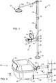
- an improved emergency wash station referred to generally in FIGURE 1 by the reference numeral 10 has an eyewash unit 12 for flushing irritants and/or contaminants such as chemicals or other toxic substances from the eyes and/or face of an individual.
- the eyewash unit 12 includes means for producing a pair of upwardly directed eyewash flush flow streams 14 ( FIG. 6 ) which diverge from each other and thereby function to flush contaminants in an inside-out, or outboard direction away from a person's tear ducts 16 and nasal or sinus cavities 18 ( FIG. 7 ).
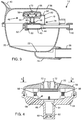
- the eyewash unit 12 generally comprises a bowl-shaped basin 20 having an upwardly open geometry and defining an open lower drain port 22 (shown best in FIG. 3 ).
- the drain port 22 merges with a drain fitting 24 adapted for coupling with a drain line 26 having an opposite end connected with a tee fitting 28 ( FIGS. 1 and 2 ) on an upright support stand 30.
- the support stand 30 has a hollow tubular construction forming a continuation of a drain path for water flow from the basin 20 to a suitable floor drain site (not shown) as via a lower tee fitting 31 ( FIG. 1 ) disposed a short distance above an enlarged lower base 32 at the bottom of the support stand 30.
- a water supply line or water supply conduit 34 extends from the support stand 30 for supplying water under pressure to the eyewash unit 12. More particularly, the water supply conduit 34 extends from a second tee fitting 36 on the support stand 30 spaced a short distance above the underlying drain line 26 and associated drain tee fitting 28, as by means of a plug member 29.
- This plug member 29 is preferably solid to preclude intermixing of the water supply and used or drain water, preferably to include a laterally open passage therein (shown best in FIG. 2 ) for clearing indicating separation of these water flows.
- An appropriate water supply source (not shown) for delivering water under pressure to the water supply line 34 is suitably coupled, e.g., via a supply tee 35 ( FIG.
- this water source may include means for providing a tempered or warm water flow, such as shown and described in U.S. Patent 5,350,112 .
- a downstream end of the water supply conduit 34 carries a pivotally mounted dust cover 38 movable between an open position ( FIG. 1 ) exposing an eyewash body 48, and a closed position ( FIGS. 2-3 ) overlying and concealing the eyewash body 48 within the basin 20.
- a handle or activation flag 40 located on the upper front of the cover 38 is easily grasped by the left or right hand for quick and easy displacement from the closed position to the open position, when emergency use of the eyewash unit 12 is desired or required.
- the cover 38 is pivotally coupled to a valved connector 42 ( FIGS.
- valved operation for an emergency eyewash station is known in the art, e.g. , as disclosed in U.S. Patent 5,754,990 .
- An elbow or L-shaped strainer 44 ( FIG. 3 ) is coupled as by means of a threaded connection with a downstream end of the valved pivotal connection 42 which is mounted in turn at a downstream end of the water supply conduit 34.
- the L-strainer 44 can be connected directly to the downstream end of the water supply conduit 34. As shown best in FIG. 3 , this L-strainer extends into the lower basin 20, and defines an upwardly directed threaded fitting 46 for quick and easy removable mounting of the eyewash body 48 forming the eyewash unit 12.
- the L-strainer 44 may additionally include a cylindrical strainer screen 45 for straining particulate from the water supply stream prior to water flow upwardly through the threaded fitting 46 to the eyewash body 48.
- a horizontally open discharge port 50 is normally closed by a threaded plug 52 or the like, wherein this plug 52 can be removed as needed for easy access to and cleaning of the L-strainer interior and the strainer screen 45 contained therein, with flush flow of water during such cleaning passing through the discharge port 50 and into the basin 20 for drainage therefrom.
- the eyewash body 48 comprises a relatively compact subassembly or module including a lower base member 54 having an upper discharge plate 56 attached thereto as by means of a pair of screws 58 ( FIGS. 3-4 ).
- a lower central threaded fitting 60 depends from the underside of the base member 54 for quick and easy threaded attachment with the upper fitting 46 on the L-strainer 44.
- this lower fitting 60 carries flow control means such as a flow restrictor 62 for providing a substantially constant water inflow upwardly and through a laminar flow screen 64 retained in place by a washer 66, and into a central eyewash body chamber 68.
- a laminar flow means such as a laminar flow cartridge 70 containing multiple laminar flow screens, for upward discharge through a pair of discharge nozzles angularly diverging discharge ports 72 ( FIGS. 3-5 ) formed in the discharge plate 56.
- a laminar flow means such as a laminar flow cartridge 70 containing multiple laminar flow screens
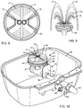
- the pair of diverging discharge ports 72 provide the pair of upwardly directed and angularly diverging eyewash flush flow streams 14 ( FIG. 6 ) to achieve the desired inside-out flush flow of contaminants from a person's face.
- These eyewash streams 14 are relatively solid, substantially laminar flow streams which arch upwardly for inside-out flush flow.
- the person's eyes are located substantially at the crests of the flush flows whereat substantial flow action with minimal kinetic energy and vertical velocity is provided. As viewed schematically in FIG.
- FIGS. 8 and 9 illustrate one alternative preferred form of the invention, wherein a modified discharge plate 56' on the eyewash body 48 additionally includes a large plurality or large array of relatively small facewash ports 74 in addition to the pair of larger eyewash ports 72.
- the overall upward water flow from the eyewash body 48 includes the pair of diverging eyewash streams 14, in combination with a large plurality of smaller facewash streams 76 ( FIG. 9 ) aimed to extend over and to drench a person's face with a flush flow of water to flush irritants or contaminants from the person's face.
- This modified discharge plate 56' mounts quickly and easily onto the lower base member 54 (not shown in FIGS. 8-9 ) of the eyewash body 48 to provide an interchangeable modular design.
- FIG. 10 shows a lock clip 78 engaged between the installed eyewash body 48 and the L-strainer 44 for normally preventing undesired rotational disassembly of the eyewash body 48 from the elbow fitting.
- the lock clip 78 comprises a relatively simple plate-shaped device having an upper tang 80 turned generally horizontally for removable attachment to a small flange 82 on the eyewash body 48, as by means of threaded fastener 84. From the upper tang 80, the lock clip 78 defines a downwardly extending plate 79 which terminates in a pair of spaced-apart or forked lower legs 86.
- These lower legs 86 are dimensioned to fit with relatively close tolerance at opposite sides of the L-strainer 44, or alternately at opposite sides of the water supply conduit 34, when the lock clip 78 is attached to the eyewash body 48.
- the depending legs 86 of the lock clip 78 effectively obstruct and thereby prevent rotational movement of the eyewash body 48 relative to the L-strainer 44, and thereby prevent undesired rotational disassembly of the eyewash body 48 unless and until the lock clip 78 is disconnected from the body flange 82.
- a tool (not shown) is required to remove the fastener 84 to achieve disassembly of the eyewash body 78 from the underlying L-strainer 44.
- FIG. 10 additionally shows the valve housing 42 connected between the water supply conduit 34 and an upstream end of the L-strainer 44, wherein this valve housing 42 has a rotatable actuator 88 for opening and closing an internal valve (not shown) within the housing 42.
- the cover 38 is connected to this rotatable actuator 88 for shifting the valve (not shown) between the closed and open positions as the cover is moved respectively between the closed and open positions, as previously described herein.
- the hinge assembly 43 on the rear margin of the cover or lid 38 is connected by a screw 87 or the like to a bracket plate 89 forming part of the rotatable actuator 88.
- FIGS. 11-12 illustrate a further adaptation of the invention, wherein an emergency shower station 90 ( FIGS. 1 , 11 and 12 ) is included as part of the emergency wash station 10.
- the support stand 30 continues upwardly from the water supply tee fitting 35 to an upper elbow 92 whereat a second water supply conduit 94 extends generally horizontally to an emergency shower head 96 ( FIGS. 11-12 ).
- a valve housing 98 is included along the conduit 94 and is adapted for quick and easy emergency opening, as by means of pull cord 100 and handle 102 ( FIG. 1 ) for providing water under pressure to the shower head 96.
- the wash station 10 thus also accommodates, when needed, emergency shower wash-off of irritants or contaminants from a person.
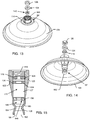
- FIGS. 11-12 show an improved subassembly including the emergency shower head 96 carrying a downwardly open, generally inverted bell-shaped shower shroud 104.
- the shower head 96 comprises a compact body having a threaded upstream end 106 for quick and easy threaded connection with a downstream end of an elbow fitting 108 ( FIG. 1 ) attached to the water supply conduit 94.
- Rotational mounting and/or rotational disassembly of the shower head 96 is achieved by means of a tool (not shown) engaging wrench flats 110 formed on a downstream nozzle portion 112 of the shower head body.
- the shroud 104 is carried on the shower head 96 in a manner permitting rotation shroud displacement relative to the shower head 96, without rotational disassembly of the shower head 96 from the associated conduit fitting 108. That is, as shown best in FIG. 12 , the shroud 104 includes a central hub 114 which is rotatably carried about the body of the shower head 96 between a pair of retaining rings 116 which prevent any significant axial displacement of the shroud 104. Alternately, if desired, one of the retaining rings 116 can be substituted by other retaining means, such as a radially enlarged shoulder on the shower head body. With this construction, rotational displacement of the shroud 104 does not loosen or disassemble the shower head 96.
- FIGS. 13-19 show a preferred construction for the shower head including the rotatable shroud 104.
- the shower head includes a modified nozzle subassembly in the form of a nozzle body 96' having a plurality of flow control and stream shaping components mounted therein, wherein this modified combination is designed to provide a regulated outflow of shower water which is substantially constant over a range of normal water inflow pressures, and further wherein the produced shower stream is relatively uniformly dispersed throughout a defined generally cone-shaped shower spray pattern to insure thorough rinsing of contaminants from a person using the shower.
- the modified shower head combination is designed for substantially complete compliance with applicable safety codes and standards.
- the modified nozzle body 96' comprises a unitary structure having an upstream end 118 that is internally threaded for threaded mounting onto the downstream end of the shower water supply conduit 94 (as viewed in FIG. 1 ), as by appropriate coupling to a downstream end of the elbow fitting 108 mounted onto the conduit 94.
- the outer surface of the modified nozzle body 96' includes a radially enlarged shoulder 120 for seating against an upper side of the hub 114 of the shroud 104, in combination with a ring groove 1 22 ( FIG. 15 ) in axially spaced related to said shoulder 1 20 for receiving a retaining ring 116 ( FIG. 12 ) for supporting the shroud 104 on the nozzle body 96' while permitting relatively free rotation between the shroud 104 and the nozzle body 96'.
- the interior of the modified nozzle body 96' includes a number of stepped shoulders formed therein to define mounting stops for each of the multiple flow control and stream shaping components to be mounted therein.
- an upper shoulder 124 is formed generally at the downstream end of the internally threaded end 118.
- This upper shoulder 124 defines a stop for seated support of a flexible pressure compensating flow control element 126.
- This flow control element 126 shown in more detail in FIG. 16 , comprises a resilient or flexible ring mounted along a central flow path 127 through the nozzle body 96', and defines a central flow control port 128.
- External tabs may be provided on the periphery of the flow control element 126 to assist in locating and retaining the element 126 relative to the threaded end 118 of the nozzle body 96'.
- the flow control port 128 is designed for regulating the rate of water flow through the element 126 to a substantially constant water outflow in response to a range of different upstream water supply pressures.
- the flow control element 126 is designed to maintain a substantially constant water outflow of at least about 1.26L/sec (20 gallons per minute) in response to water supply pressures within a normal pressure range of about 206.84kPa (30psi) to about 620.53kPa (90 psi).
- a preferred flow control element 126 defines the flow control port 128 with a beveled or smoothly radiused upstream edge (arrow 130), in combination with an axially inset downstream margin (arrow 132).
- the flow control port 128 is able to effectively shift in diametric size to achieve the desired substantially constant water outflow rate.
- a preferred diametric size is about 11.13mm (0.438 inch)
- a preferred axial thickness is about 10.16mm (0.4 inch).
- the flow control element 126 is, in the preferred form as shown best in FIG. 15 , spaced a short distance axially upstream from a flow control positioning spacer or washer 134.
- a flow control positioning spacer or washer 134 spaced a short distance axially upstream from a flow control positioning spacer or washer 134.
- the flow control spacer washer 134 comprises a relatively sturdy, or substantially non-flexible or rigid component seated within the nozzle body 96' against a second, slightly smaller diameter internal step shoulder 136.
- the spacer washer 134 (shown best in FIG. 17 ) defines a central flow port 138 having a diametric size that is larger than the size of the flow control port 128 formed in the flow control element 126.
- the diametric size of the central flow port 138 in the spacer washer 136 is about 13.46mm (0.530 inch), whereas the diametric size of the preferred flow control port 128 in the element 126 is about 10.92mm (0.438 inch).
- the spacer washer 136 functions by substantially reducing turbulent flow while converting the water passing therethrough to a substantially unified or columnar stream approaching laminar flow characteristics. Such reduced turbulence is enhanced by increasing the thickness of the spacer washer, with a washer thickness of about 5.97mm (0.235 inch) in the preferred form, and by smoothly beveling the upstream and downstream edges of the central flow port 1 38 (as indicated in FIG. 17 by arrows 140 and 142, respectively).
- the discharged water stream passes into an axially elongated first mixing chamber 144 ( FIG. 15 ) located between the washer 134 and a diffuser disk 146.
- the diffuser disk is shown in more detail in FIGS. 18-19 .
- the diffuser disk 146 comprises an annular ring 148 defining a flow port 1 50 having conically tapered upstream and downstream ends, in combination with a plurality of outwardly radiating swirl vanes 152 set angularly to define a corresponding plurality of angled swirl passages 154.
- the outer peripheries of these vanes 1 52 are sized to rest and seat upon a third and slightly smaller diameter internally stepped shoulder 1 56 formed within the nozzle body 96'.
- swirl vanes 152 there are four swirl vanes 152 each set at an angle of about 45 to an axial centerline of the nozzle body 96'.
- the diametric size of the flow port 150 in the diffuser disk 146 is less than the diametric size of the central flow port 138 in the spacer washer 134, with a preferred diffuser disk flow port size being about 9.19mm (0.362 inch).
- the radial sizes of the swirl passages 154 are selected to provide the desired final shower spray pattern (as will be described in more detail), with the illustrative swirl passages 154 each being formed with a radial dimension of about 8.56mm (0.337 inch).
- water discharged through the spacer washer 134 substantially in the form of a unified stream. At least a portion of this water stream impacts the annular ring 148 of the diffuser disk 146, thereby creating turbulence at the upstream side of the diffuser disk.
- the result is that a portion of the water discharged through the spacer washer 134 passes axially through the diffuser disk flow port 150, and another portion of this water passes with a spinning or swirling action through the swirl passages 154 defined between the angularly set swirl vanes 152.
- the axial length of the first mixing chamber 144 is sufficiently long, preferably at least about equal to the mixing chamber diametric size, with the illustrative drawings showing a mixing chamber length of at least about 25.4mm (1.0 inch), and more preferably about 33mm (1.3 inches).
- the combined water flow passing through the diffuser disk 146 enters a second mixing chamber 1 56 defining a short axial spacing between the diffuser disk 146 and a nozzle orifice 158 formed in the nozzle body 96'.
- the nozzle orifice 158 has a diametric size greater than the size of the central flow port 150 in the diffuser disk 146 to align generally axially with the annular ring 148 of the diffuser disk.
- a preferred size for the nozzle orifice 158 is about 12.7mm (0.5 inch).
- This size in combination with inwardly angled walls 160 on the nozzle body 96' defining a downstream segment of the second mixing chamber 156 causes further mixing of the stream-like water passing through the flow port 150 of the diffuser disk 146 with the swirling outer water flows passing through the swirl passages 1 54.
- the water discharged from the nozzle orifice 158 flows into a conically expanding exit cone 162 which permits the swirling water portion to expand by centrifugal action radially outwardly within the limits of the exit cone geometry. Importantly, this creates a substantially uniform water distribution or dispersion over the entire volume discharged from the nozzle body 96' for effective washing of contaminants from a person using the shower.
- the exit cone 162 in the preferred form defines a first cone segment 164 angling outwardly from the nozzle orifice 1 58 at an included angle of about 45 relative to an axial centerline of the nozzle body 96', and then merging with a second cone segment 166 angling outwardly at an included angle of about 30 from said centerline.
- a curved surface may be used in lieu of the two relatively straight conical segments.
- the emergency wash station 10 may be constructed to include only the eyewash unit 12, or the combined eyewash/facewash unit, and/or additionally include the emergency shower unit 90.
- the unit can be adapted for pole mounting as shown, or alternately for pedestal or wall mounting as known by persons skilled in the art.
- the unit may be incorporated into a portable or gravity feed eyewash unit such as the type shown in U.S. Patent D529,185 .
- the components of the eyewash body 48 can be constructed from a lightweight molded plastic which may incorporate an antimicrobial substance. Accordingly, no limitation on the invention is intended by way of the foregoing description and accompanying drawings, except as set forth in the appended claims.
Landscapes
- Health & Medical Sciences (AREA)
- Ophthalmology & Optometry (AREA)
- Epidemiology (AREA)
- Pain & Pain Management (AREA)
- Physical Education & Sports Medicine (AREA)
- Rehabilitation Therapy (AREA)
- Life Sciences & Earth Sciences (AREA)
- Animal Behavior & Ethology (AREA)
- General Health & Medical Sciences (AREA)
- Public Health (AREA)
- Veterinary Medicine (AREA)
- Devices For Medical Bathing And Washing (AREA)
- Nozzles (AREA)
- Bathtubs, Showers, And Their Attachments (AREA)
Description
- This invention relates generally to improvements in emergency eyewash stations designed particularly for use in a laboratory or industrial environment to provide a flush flow of water to remove irritants and/or contaminants from a person's eyes. More specifically, this invention relates to an improved emergency eyewash unit for providing an improved inside-out directed flush flow of water. In various preferred embodiments, the improved eyewash unit may additionally provide a facewash flush flow and/or an overhead emergency shower.
- Emergency eyewash stations are generally known in the art for use in washing or flushing toxic substances from a person's eyes. Such eyewash stations are commonly used in laboratory and/or industrial applications wherein personnel are required to handle or otherwise work in proximity with substances which can be potentially harmful if contacted with the eyes. A typical eyewash station includes one or more spray nozzles or spray heads mounted over or in close association with an appropriate sink or drain, with means for rapidly and easily opening a valve to provide a flushing flow of water to a person's eyes and/or face to flush irritants and contaminants therefrom.
- In the past, emergency eyewash stations have generally provided a pair of upwardly directed converging water streams for flushing contaminants from the eyes and face. See, for example,
U.S. Patents 5,740,469 and5,754,990 which depict a pair of spray heads oriented to deliver a respective pair of water streams upwardly and angularly converging toward each other. However, such converging flush flow streams tend to wash contaminants located in or around a person's eyes in an outside-in, or inward, direction toward the person's tear ducts and sinus cavities. Accordingly, the inward-directed flush flows may carry the contaminants into contact with these anatomical structures where tissue damage can be increased. In addition, in the case of fluids washing into and around the nose, sinus cavities, and mouth, such fluids can be ingested and/or swallowed thereby further spreading the contaminants. - Another known eyewash station is shown in
US 5170518 which fits on a water outlet and directs two streams in a forward and upward direction. -
US 5 170 518 A mentioned above discloses an emergency eyewash unit, comprising eyewash means including an eyewash body, the eyewash body defining an inlet fitting for connection to a water supply conduit, the eyewash body having at least a pair of diverging water discharge ports formed therein, wherein the pair of water discharge ports are configured to provide a pair of eyewash flush flow water streams that are angularly diverging. - There exists a significant need for improvements in and to eyewash stations, particularly with respect to providing improved water-flow flushing of contaminants from a person's eyes while reducing or eliminating contaminant contact with the person's tear ducts and/or sinus cavities. The present invention fulfills these needs and provides further related advantages.
- The invention provides an emergency eyewash unit as defined in claim 1 below. Optimal features are set out in the dependent claims.
- According to the invention, the eyewash unit comprises an eyewash body adapted for connection to a water supply line or conduit. The eyewash body defines an upper discharge plate having a pair of diverging flow ports formed therein for upward projection therethrough of the pair of diverging eyewash flush flow water streams. These diverging flush flow streams are effective to wash or flush irritants and contaminants from a person's eyes in an inside-out direction, thereby flushing in a direction away from the person's tear ducts and sinus cavities.
- In one alternative preferred form, the upper discharge plate may additionally include a plurality of small facewash perforations for upward flow of a corresponding plurality of relatively small facewash flush flow streams effective to flush irritants and contaminants from the person's face, in addition to the two diverging eyewash flush flow streams.
- The eyewash body including the upper perforated discharge plate is adapted for quick and easy mounting as a unit with respect to a water supply line, preferably in a position generally within or centered over a drain basin. In the preferred form, an elbow or L-shaped strainer is coupled to a downstream end of the water supply line, and the eyewash body in turn includes a threaded fitting for threaded connection with the elbow fitting. A lock clip is removably attached to the eyewash body, as by means of a threaded fastener connecting the lock clip to a short flange on the eyewash body. The lock clip defines a forked leg structure having a pair of spaced-apart legs disposed on opposite sides of the water supply conduit. This pair of lock clip legs thus engage the water supply conduit to prevent rotational disassembly of the eyewash body from the associated L-strainer and water supply conduit, unless and until the lock clip is first disconnected from the eyewash body.
- In a further alternative preferred form of the invention, the eyewash and/or combined eyewash/facewash unit may be additionally combined with an overhead emergency shower used to wash irritants and contaminants from a person's body. In the preferred form, the overhead shower comprises a spray head or spray nozzle adapted for installation at a downstream end of a water supply line or conduit to provide a downwardly directly shower spray aimed preferably to deluge a person using the eyewash or combined eyewash/facewash unit. The shower spray head may be adapted for thread-on mounting at the downstream end of the water supply line. A downwardly open shroud element is carried by the spray head generally in surrounding relation thereto. In the preferred form, the shroud element is rotatably mounted on the spray head but axially constrained by at least one snap ring to prevent rotational removal of the shroud element from the spray head.
- A preferred shower head further comprises a nozzle body having a plurality of flow control and stream shaping components mounted therein, wherein this modified combination is designed to provide a regulated outflow of shower water which is substantially constant over a range of normal water inflow pressures, and further wherein the produced shower stream is relatively uniformly dispersed throughout a defined generally cone-shaped shower spray pattern to insure thorough rinsing of contaminants from a person using the shower. In this regard, the modified shower head combination is designed for substantially complete compliance with applicable safety codes and standards.
- The preferred shower head includes a flexible pressure compensating flow control element for regulating the rate of water flow in response to a range of different upstream water supply pressures. This flow control element is mounted upstream from a flow control positioning or spacer washer designed to remove turbulence from the water flow stream. Water discharged from the spacer washer is directed into an axially elongated mixing chamber before encountering a diffuser disk which converts the water flow into a central stream and a spinning or swirling outer portion. The combined stream is directed through a short mixing chamber to a nozzle orifice which in turn supplies to the water via a exit cone for final shaping into a substantially uniformly dispersed conical shower spray pattern. A preferred exit cone geometry includes multiple conical segments defined by a progressively decreasing taper angle.
- Other features and advantages of the present invention will become more apparent from the following detailed description taken in conjunction with the accompanying drawings which illustrate, by way of example, the principles of the invention.
- The accompanying drawings illustrate the invention. In such drawings:
-
FIGURE 1 is a perspective view of a combined emergency eyewash and emergency shower station, and depicting an emergency eyewash unit with a protective cover in an open position; -
FIGURE 2 is an enlarged and fragmented perspective view showing the emergency eyewash unit ofFIG. 1 with the protective cover in a normal closed position; -
FIGURE 3 is an enlarged vertical sectional view taken generally on the line 3-3 ofFIG. 2 , and illustrating an eyewash body coupled to a water supply line or conduit; -
FIGURE 4 is a further enlarged vertical sectional view showing internal construction details of the eyewash body ofFIG. 3 ; -
FIGURE 5 is a top plan view of the eyewash body, taken generally on the line 5-5 ofFIG. 4 ; -
FIGURE 6 is a simplified perspective view showing two angularly diverging water flush streams projected upwardly from the eyewash body ofFIGS. 3-5 ; -
FIGURE 7 is a diagrammatic view representing operation of the diverging water flush streams to flush contaminants from a person's eyes by water flow in an inside-out direction; -
FIGURE 8 is a to plan view similar toFIG. 5 , but showing an alternative preferred form of the eyewash body to include a plurality of perforated ports for use as a combined eyewash/facewash unit; -
FIGURE 9 is a simplified perspective view similar toFIG. 6 , but showing a plurality of relative small facewash streams in combination the diverging eyewash flush streams directed upwardly from the modified eyewash body ofFIG. 8 ; -
FIGURE 10 is a top perspective view of the eyewash unit illustrating a lock clip for preventing rotational disassembly of the eyewash body from the unit; -
FIGURE 11 is a bottom side perspective view of a shower head for use in the combined eyewash and emergency shower station ofFIG. 1 ; -
FIGURE 12 is a vertical sectional view taken generally on the line 12-12 ofFIG. 11 ; -
FIGURE 1 3 is an exploded top perspective view of one preferred shower head construction included multiple flow control and stream shaping components mounted within a modified nozzle body; -
FIGURE 14 is an exploded bottom perspective view of the shower head construction shown inFIG. 13 ; -
FIGURE 1 5 is a vertical sectional view illustrating the nozzle body ofFIGS. 13-14 with the multiple flow control and stream shaping components mounted therein; -
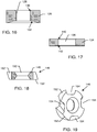
FIGURE 16 is an enlarged vertical sectional view of a pressure compensating flexible flow control element for mounting into the nozzle body ofFIGS. 13-15 ; -
FIGURE 1 7 is an enlarged vertical sectional view of a flow control positioning washer for mounting into the nozzle body ofFIGS. 13-15 ; -
FIGURE 18 is an enlarged vertical sectional view of a diffuser disk for mounting into the nozzle body ofFIGS. 13-15 ; and -
FIGURE 19 is a perspective view of the diffuser disk ofFIG. 18 . - As shown in the exemplary drawings, an improved emergency wash station referred to generally in
FIGURE 1 by thereference numeral 10 has aneyewash unit 12 for flushing irritants and/or contaminants such as chemicals or other toxic substances from the eyes and/or face of an individual. Theeyewash unit 12 includes means for producing a pair of upwardly directed eyewash flush flow streams 14 (FIG. 6 ) which diverge from each other and thereby function to flush contaminants in an inside-out, or outboard direction away from a person'stear ducts 16 and nasal or sinus cavities 18 (FIG. 7 ). - As shown in
FIGS. 1-3 , theeyewash unit 12 generally comprises a bowl-shapedbasin 20 having an upwardly open geometry and defining an open lower drain port 22 (shown best inFIG. 3 ). Thedrain port 22 merges with a drain fitting 24 adapted for coupling with adrain line 26 having an opposite end connected with a tee fitting 28 (FIGS. 1 and 2 ) on anupright support stand 30. Although not shown in detail in the accompanying drawings, persons skilled in the art will appreciate that thesupport stand 30 has a hollow tubular construction forming a continuation of a drain path for water flow from thebasin 20 to a suitable floor drain site (not shown) as via a lower tee fitting 31 (FIG. 1 ) disposed a short distance above an enlargedlower base 32 at the bottom of thesupport stand 30. - A water supply line or
water supply conduit 34 extends from the support stand 30 for supplying water under pressure to theeyewash unit 12. More particularly, thewater supply conduit 34 extends from a second tee fitting 36 on the support stand 30 spaced a short distance above theunderlying drain line 26 and associated drain tee fitting 28, as by means of aplug member 29. Thisplug member 29 is preferably solid to preclude intermixing of the water supply and used or drain water, preferably to include a laterally open passage therein (shown best inFIG. 2 ) for clearing indicating separation of these water flows. An appropriate water supply source (not shown) for delivering water under pressure to thewater supply line 34 is suitably coupled, e.g., via a supply tee 35 (FIG. 1 ) or the like coupled to the tee fitting 36 as by means of an upper segment of thesupport stand 30. If desired, this water source may include means for providing a tempered or warm water flow, such as shown and described inU.S. Patent 5,350,112 . - A downstream end of the
water supply conduit 34 carries a pivotally mounteddust cover 38 movable between an open position (FIG. 1 ) exposing aneyewash body 48, and a closed position (FIGS. 2-3 ) overlying and concealing theeyewash body 48 within thebasin 20. A handle oractivation flag 40 located on the upper front of thecover 38 is easily grasped by the left or right hand for quick and easy displacement from the closed position to the open position, when emergency use of theeyewash unit 12 is desired or required. In this regard, thecover 38 is pivotally coupled to a valved connector 42 (FIGS. 3 and10 ) on thewater supply conduit 34 as by means of ahinge assembly 43 to actuate a valve (not shown) for initiating water flow to theeyewash unit 12, upon cover movement to the open position. Such valved operation for an emergency eyewash station is known in the art, e.g., as disclosed inU.S. Patent 5,754,990 . - An elbow or L-shaped strainer 44 (
FIG. 3 ) is coupled as by means of a threaded connection with a downstream end of the valvedpivotal connection 42 which is mounted in turn at a downstream end of thewater supply conduit 34. Alternately, when an alternative on-off valve actuation means is used, the L-strainer 44 can be connected directly to the downstream end of thewater supply conduit 34. As shown best inFIG. 3 , this L-strainer extends into thelower basin 20, and defines an upwardly directed threaded fitting 46 for quick and easy removable mounting of theeyewash body 48 forming theeyewash unit 12. If desired, the L-strainer 44 may additionally include acylindrical strainer screen 45 for straining particulate from the water supply stream prior to water flow upwardly through the threaded fitting 46 to theeyewash body 48. A horizontallyopen discharge port 50 is normally closed by a threadedplug 52 or the like, wherein thisplug 52 can be removed as needed for easy access to and cleaning of the L-strainer interior and thestrainer screen 45 contained therein, with flush flow of water during such cleaning passing through thedischarge port 50 and into thebasin 20 for drainage therefrom. - The
eyewash body 48 comprises a relatively compact subassembly or module including alower base member 54 having anupper discharge plate 56 attached thereto as by means of a pair of screws 58 (FIGS. 3-4 ). A lower central threadedfitting 60 depends from the underside of thebase member 54 for quick and easy threaded attachment with theupper fitting 46 on the L-strainer 44. As shown, this lower fitting 60 carries flow control means such as aflow restrictor 62 for providing a substantially constant water inflow upwardly and through alaminar flow screen 64 retained in place by awasher 66, and into a centraleyewash body chamber 68. From thiscentral chamber 68, the water is permitted to flow further upwardly through a laminar flow means such as alaminar flow cartridge 70 containing multiple laminar flow screens, for upward discharge through a pair of discharge nozzles angularly diverging discharge ports 72 (FIGS. 3-5 ) formed in thedischarge plate 56. Persons skilled in the art will recognize and appreciate that alternative flow control structures and alternative laminar flow structures can be used. - The pair of diverging
discharge ports 72 provide the pair of upwardly directed and angularly diverging eyewash flush flow streams 14 (FIG. 6 ) to achieve the desired inside-out flush flow of contaminants from a person's face. These eyewash streams 14 are relatively solid, substantially laminar flow streams which arch upwardly for inside-out flush flow. As a person leans over these eyewash streams 14, the person's eyes are located substantially at the crests of the flush flows whereat substantial flow action with minimal kinetic energy and vertical velocity is provided. As viewed schematically inFIG. 7 , such inside-out, or outboard directed flush flow generally in the direction ofarrow 73, beneficially washes any irritants or contaminants on or near theeyes 75 in an outboard direction away from a person's tear ducts (lacrimal punctum) 16 and the adjacent nasal andsinus cavities 18. As a result, the contaminants are substantially prevented from contacting these tissue structures where they can otherwise be ingested to cause wider irritation and potential tissue damage. The flush flow water falls from the person's face downwardly into theopen basin 20 for collection and further passage through thedrain port 22 anddrain conduit 24. -
FIGS. 8 and 9 illustrate one alternative preferred form of the invention, wherein a modified discharge plate 56' on theeyewash body 48 additionally includes a large plurality or large array of relativelysmall facewash ports 74 in addition to the pair oflarger eyewash ports 72. When thesesmall facewash ports 74 are included, the overall upward water flow from theeyewash body 48 includes the pair of diverging eyewash streams 14, in combination with a large plurality of smaller facewash streams 76 (FIG. 9 ) aimed to extend over and to drench a person's face with a flush flow of water to flush irritants or contaminants from the person's face. This modified discharge plate 56' mounts quickly and easily onto the lower base member 54 (not shown inFIGS. 8-9 ) of theeyewash body 48 to provide an interchangeable modular design. -
FIG. 10 shows alock clip 78 engaged between the installedeyewash body 48 and the L-strainer 44 for normally preventing undesired rotational disassembly of theeyewash body 48 from the elbow fitting. As shown, thelock clip 78 comprises a relatively simple plate-shaped device having anupper tang 80 turned generally horizontally for removable attachment to asmall flange 82 on theeyewash body 48, as by means of threadedfastener 84. From theupper tang 80, thelock clip 78 defines a downwardly extendingplate 79 which terminates in a pair of spaced-apart or forkedlower legs 86. Theselower legs 86 are dimensioned to fit with relatively close tolerance at opposite sides of the L-strainer 44, or alternately at opposite sides of thewater supply conduit 34, when thelock clip 78 is attached to theeyewash body 48. With this construction, the dependinglegs 86 of thelock clip 78 effectively obstruct and thereby prevent rotational movement of theeyewash body 48 relative to the L-strainer 44, and thereby prevent undesired rotational disassembly of theeyewash body 48 unless and until thelock clip 78 is disconnected from thebody flange 82. A tool (not shown) is required to remove thefastener 84 to achieve disassembly of theeyewash body 78 from the underlying L-strainer 44. -
FIG. 10 additionally shows thevalve housing 42 connected between thewater supply conduit 34 and an upstream end of the L-strainer 44, wherein thisvalve housing 42 has arotatable actuator 88 for opening and closing an internal valve (not shown) within thehousing 42. Thecover 38 is connected to thisrotatable actuator 88 for shifting the valve (not shown) between the closed and open positions as the cover is moved respectively between the closed and open positions, as previously described herein. Thehinge assembly 43 on the rear margin of the cover orlid 38 is connected by ascrew 87 or the like to abracket plate 89 forming part of therotatable actuator 88. With this construction, normal raising and lowering of thecover 38 shifts thebracket plate 89 relative to theconnector 42 for respectively opening and closing a valve (not shown) within theconnector 42. However, upon removal of thescrew 87, thecover 38 is rotatable relative to thebracket plate 89 via a pivot joint 91, whereby thecover 38 can be opened without turning on the water flow as may be desired, e.g., when flushing thefilter screen 45 within the L-strainer 44. -
FIGS. 11-12 illustrate a further adaptation of the invention, wherein an emergency shower station 90 (FIGS. 1 ,11 and 12 ) is included as part of theemergency wash station 10. As shown best inFIG. 1 , thesupport stand 30 continues upwardly from the water supply tee fitting 35 to anupper elbow 92 whereat a secondwater supply conduit 94 extends generally horizontally to an emergency shower head 96 (FIGS. 11-12 ). Avalve housing 98 is included along theconduit 94 and is adapted for quick and easy emergency opening, as by means ofpull cord 100 and handle 102 (FIG. 1 ) for providing water under pressure to theshower head 96. Thewash station 10 thus also accommodates, when needed, emergency shower wash-off of irritants or contaminants from a person. -
FIGS. 11-12 show an improved subassembly including theemergency shower head 96 carrying a downwardly open, generally inverted bell-shapedshower shroud 104. In accordance with the invention, theshower head 96 comprises a compact body having a threadedupstream end 106 for quick and easy threaded connection with a downstream end of an elbow fitting 108 (FIG. 1 ) attached to thewater supply conduit 94. Rotational mounting and/or rotational disassembly of theshower head 96 is achieved by means of a tool (not shown) engagingwrench flats 110 formed on adownstream nozzle portion 112 of the shower head body. - Importantly, the
shroud 104 is carried on theshower head 96 in a manner permitting rotation shroud displacement relative to theshower head 96, without rotational disassembly of theshower head 96 from the associated conduit fitting 108. That is, as shown best inFIG. 12 , theshroud 104 includes acentral hub 114 which is rotatably carried about the body of theshower head 96 between a pair of retainingrings 116 which prevent any significant axial displacement of theshroud 104. Alternately, if desired, one of the retaining rings 116 can be substituted by other retaining means, such as a radially enlarged shoulder on the shower head body. With this construction, rotational displacement of theshroud 104 does not loosen or disassemble theshower head 96. -
FIGS. 13-19 show a preferred construction for the shower head including therotatable shroud 104. In this preferred form, the shower head includes a modified nozzle subassembly in the form of a nozzle body 96' having a plurality of flow control and stream shaping components mounted therein, wherein this modified combination is designed to provide a regulated outflow of shower water which is substantially constant over a range of normal water inflow pressures, and further wherein the produced shower stream is relatively uniformly dispersed throughout a defined generally cone-shaped shower spray pattern to insure thorough rinsing of contaminants from a person using the shower. In this regard, the modified shower head combination is designed for substantially complete compliance with applicable safety codes and standards. - More particularly, as viewed best in
FIGS. 13-15 , the modified nozzle body 96' comprises a unitary structure having anupstream end 118 that is internally threaded for threaded mounting onto the downstream end of the shower water supply conduit 94 (as viewed inFIG. 1 ), as by appropriate coupling to a downstream end of the elbow fitting 108 mounted onto theconduit 94. The outer surface of the modified nozzle body 96' includes a radiallyenlarged shoulder 120 for seating against an upper side of thehub 114 of theshroud 104, in combination with a ring groove 1 22 (FIG. 15 ) in axially spaced related to said shoulder 1 20 for receiving a retaining ring 116 (FIG. 12 ) for supporting theshroud 104 on the nozzle body 96' while permitting relatively free rotation between theshroud 104 and the nozzle body 96'. - The interior of the modified nozzle body 96' includes a number of stepped shoulders formed therein to define mounting stops for each of the multiple flow control and stream shaping components to be mounted therein. Specifically, an
upper shoulder 124 is formed generally at the downstream end of the internally threadedend 118. Thisupper shoulder 124 defines a stop for seated support of a flexible pressure compensatingflow control element 126. Thisflow control element 126, shown in more detail inFIG. 16 , comprises a resilient or flexible ring mounted along acentral flow path 127 through the nozzle body 96', and defines a centralflow control port 128. External tabs (not shown) may be provided on the periphery of theflow control element 126 to assist in locating and retaining theelement 126 relative to the threadedend 118 of the nozzle body 96'. - As is known in the art, the
flow control port 128 is designed for regulating the rate of water flow through theelement 126 to a substantially constant water outflow in response to a range of different upstream water supply pressures. In the illustrative embodiment, theflow control element 126 is designed to maintain a substantially constant water outflow of at least about 1.26L/sec (20 gallons per minute) in response to water supply pressures within a normal pressure range of about 206.84kPa (30psi) to about 620.53kPa (90 psi). As shown inFIG. 16 , a preferredflow control element 126 defines theflow control port 128 with a beveled or smoothly radiused upstream edge (arrow 130), in combination with an axially inset downstream margin (arrow 132). With this geometry, theflow control port 128 is able to effectively shift in diametric size to achieve the desired substantially constant water outflow rate. In an unstressed state, a preferred diametric size is about 11.13mm (0.438 inch), and a preferred axial thickness is about 10.16mm (0.4 inch). - The
flow control element 126 is, in the preferred form as shown best inFIG. 15 , spaced a short distance axially upstream from a flow control positioning spacer orwasher 134. However, persons skilled in the art will recognize and appreciate that the axially insetdownstream margin 132 circumscribing theflow control port 128 permits proper regulatory operation by theflow control element 126 in the event that this axial spacing is eliminated. - The flow
control spacer washer 134 comprises a relatively sturdy, or substantially non-flexible or rigid component seated within the nozzle body 96' against a second, slightly smaller diameterinternal step shoulder 136. The spacer washer 134 (shown best inFIG. 17 ) defines acentral flow port 138 having a diametric size that is larger than the size of theflow control port 128 formed in theflow control element 126. In a preferred form, the diametric size of thecentral flow port 138 in thespacer washer 136 is about 13.46mm (0.530 inch), whereas the diametric size of the preferredflow control port 128 in theelement 126 is about 10.92mm (0.438 inch). Thespacer washer 136 functions by substantially reducing turbulent flow while converting the water passing therethrough to a substantially unified or columnar stream approaching laminar flow characteristics. Such reduced turbulence is enhanced by increasing the thickness of the spacer washer, with a washer thickness of about 5.97mm (0.235 inch) in the preferred form, and by smoothly beveling the upstream and downstream edges of the central flow port 1 38 (as indicated inFIG. 17 byarrows - From the flow
control spacer washer 134, the discharged water stream passes into an axially elongated first mixing chamber 144 (FIG. 15 ) located between thewasher 134 and adiffuser disk 146. The diffuser disk is shown in more detail inFIGS. 18-19 . As shown, thediffuser disk 146 comprises anannular ring 148 defining a flow port 1 50 having conically tapered upstream and downstream ends, in combination with a plurality of outwardly radiatingswirl vanes 152 set angularly to define a corresponding plurality ofangled swirl passages 154. The outer peripheries of these vanes 1 52 are sized to rest and seat upon a third and slightly smaller diameter internally stepped shoulder 1 56 formed within the nozzle body 96'. In the preferred form as shown, there are fourswirl vanes 152 each set at an angle of about 45 to an axial centerline of the nozzle body 96'. In addition, the diametric size of theflow port 150 in thediffuser disk 146 is less than the diametric size of thecentral flow port 138 in thespacer washer 134, with a preferred diffuser disk flow port size being about 9.19mm (0.362 inch). In addition, the radial sizes of theswirl passages 154 are selected to provide the desired final shower spray pattern (as will be described in more detail), with theillustrative swirl passages 154 each being formed with a radial dimension of about 8.56mm (0.337 inch). - In operation, water discharged through the
spacer washer 134 substantially in the form of a unified stream. At least a portion of this water stream impacts theannular ring 148 of thediffuser disk 146, thereby creating turbulence at the upstream side of the diffuser disk. The result is that a portion of the water discharged through thespacer washer 134 passes axially through the diffuserdisk flow port 150, and another portion of this water passes with a spinning or swirling action through theswirl passages 154 defined between the angularly set swirl vanes 152. In this regard, the axial length of thefirst mixing chamber 144 is sufficiently long, preferably at least about equal to the mixing chamber diametric size, with the illustrative drawings showing a mixing chamber length of at least about 25.4mm (1.0 inch), and more preferably about 33mm (1.3 inches). - The combined water flow passing through the
diffuser disk 146 enters a second mixing chamber 1 56 defining a short axial spacing between thediffuser disk 146 and anozzle orifice 158 formed in the nozzle body 96'. As shown inFIG. 15 , thenozzle orifice 158 has a diametric size greater than the size of thecentral flow port 150 in thediffuser disk 146 to align generally axially with theannular ring 148 of the diffuser disk. A preferred size for thenozzle orifice 158 is about 12.7mm (0.5 inch). This size, in combination with inwardly angledwalls 160 on the nozzle body 96' defining a downstream segment of thesecond mixing chamber 156 causes further mixing of the stream-like water passing through theflow port 150 of thediffuser disk 146 with the swirling outer water flows passing through the swirl passages 1 54. - The water discharged from the
nozzle orifice 158 flows into a conically expandingexit cone 162 which permits the swirling water portion to expand by centrifugal action radially outwardly within the limits of the exit cone geometry. Importantly, this creates a substantially uniform water distribution or dispersion over the entire volume discharged from the nozzle body 96' for effective washing of contaminants from a person using the shower. In the preferred form, to reduce the overall size of theexit cone 162 which additionally confining the shower spray pattern for compliance with safety codes and standards, theexit cone 162 in the preferred form defines afirst cone segment 164 angling outwardly from the nozzle orifice 1 58 at an included angle of about 45 relative to an axial centerline of the nozzle body 96', and then merging with asecond cone segment 166 angling outwardly at an included angle of about 30 from said centerline. Alternately, a curved surface may be used in lieu of the two relatively straight conical segments. - A variety of further modifications and improvements in and to the emergency wash station of the present invention will be apparent to persons skilled in the art. By way of example, the
emergency wash station 10 may be constructed to include only theeyewash unit 12, or the combined eyewash/facewash unit, and/or additionally include theemergency shower unit 90. In the eyewash and/or combined eyewash/facewash configurations, the unit can be adapted for pole mounting as shown, or alternately for pedestal or wall mounting as known by persons skilled in the art. Or, if desired, the unit may be incorporated into a portable or gravity feed eyewash unit such as the type shown inU.S. Patent D529,185 . In addition, if desired, the components of theeyewash body 48 can be constructed from a lightweight molded plastic which may incorporate an antimicrobial substance. Accordingly, no limitation on the invention is intended by way of the foregoing description and accompanying drawings, except as set forth in the appended claims.
Claims (17)
- An emergency eyewash unit (10), comprising:eyewash means (12) including an eyewash body (48), the eyewash body (48) including a lower base member (54) defining an inlet fitting (60) for connection to a water supply conduit (34), the eyewash body (48) including an upper discharge plate (56, 56') having at least a pair of diverging water discharge ports (72) formed therein, wherein the pair of water discharge ports (72) are configured to provide a pair of eyewash flush flow water streams (14) that are on the same plane, upwardly directed, angularly diverging, and wherein the plane is substantially vertical, to achieve an inside-out flush flow (73), each eyewash flush flow water stream (14) being a relatively solid, substantially laminar flow stream that arches upwardly for inside-out flush flow of contaminants from a person's eyes (75), the person's eyes in use being located substantially at the crests of the flush flow water streams; andlaminar flow means (64 and/or 70) carried within said eyewash body (48) between said inlet fitting (60) and said pair of water discharge ports (72).
- The emergency eyewash unit (10) of claim 1 wherein said eyewash body (48) further defines a plurality of relatively small facewash ports (74) for upward discharge of a plurality of relatively small facewash streams (76) to flush contaminants from a person's face.
- The emergency eyewash unit (10) of claims 1 or 2 further including flow control means (62) carried by said eyewash body (48).
- The emergency eyewash unit (10) of claim 1 further including means (78) for preventing rotational displacement of said eyewash body (48) relative to the water supply conduit (34).
- The emergency eyewash unit (10) of claim 4 further including a generally L-shaped component (44) rotatably coupled to said inlet fitting (60) and disposed between said inlet fitting (60) and the water supply conduit (34), said rotation preventing means (78) comprising a bracket plate including means (80) for removable mounting onto said eyewash body (48), and at least one depending leg (79) for engaging the water supply conduit (34) to prevent rotational removal of said eyewash body (48) from said L-shaped component (44) when said bracket plate (79, 80) is mounted onto said eyewash body (48).
- The emergency eyewash unit (10) of claim 1 wherein said eyewash means (12) is mounted within a basin (20) to catch water discharged from said pair of water discharge ports (72), said basin (20) being coupled to a water drain site (24, 26).
- The emergency eyewash unit (10) of claim 6 further including a cover (38) removably mounted over said basin (20).
- The emergency eyewash unit (10) of claim 7 wherein said cover (38) is hingedly carried on said basin (20).
- The emergency eyewash unit (10) of claim 8 further including a hinge-activated valve means (42, 43) for normally preventing water flow to said eyewash means (12) when said cover (38) is in a closed position over said basin (20), and for permitting water flow to said eyewash means (12) when said cover (38) is hingedly displaced relative to said basin (20) to an open position.
- The emergency eyewash unit (10) of claim 8 further including an easily grasped handle (40) on said cover (20).
- The emergency eyewash unit (10) of claim 1 further comprising a shower (90) including a shower head (96, 96'), and a downwardly open shroud (104) defining a hub (114) having said shower head (96, 96') mounted therein, said shroud (104) being disposed generally overhead relative to said eyewash means (12) and being carried on said shower head (96, 96') to permit shroud (104) rotation without axial displacement relative thereto.
- The emergency eyewash unit (10) of claim 11 wherein said shower head (96, 96') carries at least one retaining ring (116) for mounting said shroud (104) on said shower head (96, 96') to permit shroud (104) rotation without axial displacement relative thereto.
- The emergency eyewash unit (10) of claim 11 further comprising emergency actuated valve means (98, 100, 102) for selectively coupling water flow to said shower (90).
- The emergency eyewash unit (10) of claim 11 wherein said shower head (96') includes a nozzle subassembly having a nozzle body defining an axial flow passage (127) therethrough, a resilient flow control element (126) mounted along said flow passage (127) for regulating water flow therethrough to a substantially constant flow rate within a range of water supply pressures, a relatively non-flexible flow control positioning spacer washer (134) mounted along said flow passage (127) downstream from said flow control element (126) and having central flow port (138) therein for water passage therethrough, a diffuser disk (146) mounted along said flow passage (127) downstream from said spacer washer (134) and cooperating therewith to define a mixing chamber (144), said diffuser disk (146) having a flow port (150) formed therein having a diametric size less than the diametric size of said central flow port (138) formed in said spacer washer (134), said diffuser disk (146) further having a plurality of radially outwardly projecting swirl vanes (152) defining therebetween a corresponding plurality of angularly set swirl passages (154), whereby water flowing through said diffuser disk (146) passes through said diffuser disk flow port (150) and also through said swirl passages (154), and means defining a nozzle orifice (158) downstream from said diffuser disk (146), said nozzle orifice (158) having a diametric size greater than the diametric size of said diffuser disk flow port (150).
- The emergency eyewash unit (10) of claim 14 wherein said mixing chamber (144) has an axial length of at least about the diametric size of said mixing chamber (144).
- The emergency eyewash unit (10) of claim 14 further including an exit cone (162) formed with an expanding conical taper downstream from said nozzle orifice (158).
- The emergency eyewash unit (10) of claim 16 wherein said exit cone (162) includes a first conical segment (164) expanding outwardly from said nozzle orifice (158) with a first angular taper, and a second conical segment (166) expanding outwardly from said first conical segment with a second angular taper, said second angular taper being less than said first angular taper.
Priority Applications (1)
| Application Number | Priority Date | Filing Date | Title |
|---|---|---|---|
| EP16162238.6A EP3067036A1 (en) | 2008-05-20 | 2009-05-06 | Emergency eyewash unit |
Applications Claiming Priority (3)
| Application Number | Priority Date | Filing Date | Title |
|---|---|---|---|
| US5462608P | 2008-05-20 | 2008-05-20 | |
| PCT/US2009/043007 WO2009142912A1 (en) | 2008-05-20 | 2009-05-06 | Emergency eyewash unit |
| US12/436,425 US8316478B2 (en) | 2008-05-20 | 2009-05-06 | Emergency eyewash unit |
Related Child Applications (1)
| Application Number | Title | Priority Date | Filing Date |
|---|---|---|---|
| EP16162238.6A Division EP3067036A1 (en) | 2008-05-20 | 2009-05-06 | Emergency eyewash unit |
Publications (3)
| Publication Number | Publication Date |
|---|---|
| EP2276444A1 EP2276444A1 (en) | 2011-01-26 |
| EP2276444A4 EP2276444A4 (en) | 2012-04-25 |
| EP2276444B1 true EP2276444B1 (en) | 2016-03-30 |
Family
ID=41340466
Family Applications (2)
| Application Number | Title | Priority Date | Filing Date |
|---|---|---|---|
| EP16162238.6A Withdrawn EP3067036A1 (en) | 2008-05-20 | 2009-05-06 | Emergency eyewash unit |
| EP09751141.4A Active EP2276444B1 (en) | 2008-05-20 | 2009-05-06 | Emergency eyewash unit |
Family Applications Before (1)
| Application Number | Title | Priority Date | Filing Date |
|---|---|---|---|
| EP16162238.6A Withdrawn EP3067036A1 (en) | 2008-05-20 | 2009-05-06 | Emergency eyewash unit |
Country Status (8)
| Country | Link |
|---|---|
| US (4) | US8316478B2 (en) |
| EP (2) | EP3067036A1 (en) |
| CN (1) | CN102036643B (en) |
| AU (1) | AU2009249423B2 (en) |
| BR (1) | BRPI0912776A8 (en) |
| CA (1) | CA2723867C (en) |
| RU (1) | RU2509549C2 (en) |
| WO (1) | WO2009142912A1 (en) |
Families Citing this family (32)
| Publication number | Priority date | Publication date | Assignee | Title |
|---|---|---|---|---|
| CA2723867C (en) | 2008-05-20 | 2016-02-02 | Haws Corporation | Emergency eyewash unit |
| US20090294604A1 (en) * | 2008-05-28 | 2009-12-03 | Mark Sunderland | Pole gripping hook for medical supplies |
| US7806348B2 (en) * | 2008-06-25 | 2010-10-05 | Bradley Fixtures Corporation | Showerhead for emergency fixture |
| US8490895B2 (en) * | 2008-06-25 | 2013-07-23 | Bradley Fixtures Corporation | Showerhead for emergency fixture |
| DE202009007205U1 (en) | 2009-05-19 | 2009-10-15 | Plum A/S | eyewash |
| US9314398B2 (en) | 2009-09-08 | 2016-04-19 | Bradley Fixtures Corporation | Emergency wash system |
| US20120096639A1 (en) * | 2010-10-21 | 2012-04-26 | Haws Corporation | Faucet mounted eyewash unit |
| USD669555S1 (en) | 2011-12-02 | 2012-10-23 | Bradley Fixtures Corporation | Flow control device |
| US10973737B2 (en) | 2012-03-15 | 2021-04-13 | Magarl, Llc | Emergency wash system |
| USD740441S1 (en) * | 2013-07-08 | 2015-10-06 | Speakman Company | Eye and face wash system |
| CA2869105C (en) | 2013-10-30 | 2021-02-23 | Magarl, Llc | Eye wash system for emergency usage |
| CN103567091B (en) * | 2013-11-04 | 2016-01-13 | 江苏爵格工业设备有限公司 | One promptly washes eye and the shower nozzle that washes one's face |
| US9855189B2 (en) | 2014-06-27 | 2018-01-02 | Magarl, Llc | Flushing system for a safety system |
| CN104197084B (en) * | 2014-08-19 | 2016-04-06 | 胡敏峰 | A kind of spray eye washing device |
| GB2530075B (en) * | 2014-09-12 | 2020-05-06 | Hughes Safety Showers Ltd | Improvements in and relating to eyewashing |
| US9756988B2 (en) | 2014-10-20 | 2017-09-12 | Haws Corporation | Gravity shower |
| CN104586626A (en) * | 2015-03-01 | 2015-05-06 | 陈学红 | Sprayable eye washer |
| US10213058B2 (en) | 2015-07-11 | 2019-02-26 | Magarl, Llc | Integrated emergency wash and shower system |
| US10342389B2 (en) * | 2015-09-25 | 2019-07-09 | Magarl, Llc | Emergency wash system with pulldown eyewash and sheeting showerhead |
| US9943193B2 (en) * | 2015-10-13 | 2018-04-17 | Haws Corporation | Emergency shower with improved valve actuation |
| CN109715253B (en) * | 2016-09-21 | 2021-06-29 | 白玉锋 | Shower/emergency sprinkler/fire sprinkler head test equipment |
| CN106821714B (en) * | 2017-03-14 | 2023-05-09 | 北京大学深圳医院 | Disposable water receiver for ophthalmic nursing |
| EP3621503B1 (en) | 2017-05-11 | 2021-12-01 | Bradley Fixtures Corporation | Gravity-fed shower system and method |
| GB2563076B (en) * | 2017-06-02 | 2022-05-11 | Kohler Mira Ltd | Ablutionary fitting |
| CN107622284B (en) * | 2017-11-10 | 2018-04-24 | 孙伟 | Nasal cavity cleaning compression pump automatic regulating system |
| CN107714441A (en) * | 2017-11-15 | 2018-02-23 | 盐城市斯壮格安全设备有限公司 | Automatic-discharging anti-freeze type vertical eye washer |
| CN109125048B (en) * | 2018-10-19 | 2020-06-19 | 青岛农业大学 | Emergency eye washing device |
| CN109276443B (en) * | 2018-10-19 | 2020-09-01 | 青岛农业大学 | Eye washing device |
| CN112107474B (en) * | 2019-06-19 | 2022-09-13 | 中国石油化工股份有限公司 | Emergent eye washer that sprays that disappears of washing of chemistry handles |
| CN111773072B (en) * | 2020-07-07 | 2022-06-24 | 芜湖晟汇信息科技有限公司 | Ophthalmic eye cleaning equipment |
| RU206095U1 (en) * | 2021-03-18 | 2021-08-23 | Илья Александрович Куратов | Nasal flushing apparatus |
| CN113288784B (en) * | 2021-06-11 | 2023-03-31 | 中国人民解放军陆军军医大学第一附属医院 | Lacrimal passage irrigation water collecting device |
Family Cites Families (56)
| Publication number | Priority date | Publication date | Assignee | Title |
|---|---|---|---|---|
| NL282740A (en) | 1961-10-23 | |||
| US3563469A (en) * | 1969-02-18 | 1971-02-16 | Wolverine Brass Works | Shower head with rotatable valving members |
| US3602436A (en) * | 1969-03-20 | 1971-08-31 | Haws Drinking Faucet Co | Spray nozzle for an eyewash fountain |
| US3809315A (en) | 1972-10-04 | 1974-05-07 | Haws Drinking Fountain Co | Eyewash fountain and nozzle structure therefor |
| US3865310A (en) * | 1974-04-12 | 1975-02-11 | Teledyne Ind | Bracket assembly for hand-held showerhead |
| US3925829A (en) | 1974-08-12 | 1975-12-16 | Howard W Bost | Emergency eye wash fountain apparatus |
| US4012798A (en) | 1975-09-29 | 1977-03-22 | Liautaud John R | Portable emergency eye wash fountain |
| US4055301A (en) * | 1976-07-19 | 1977-10-25 | Rain Jet Corporation | Shower head with divergent impact effect nozzle |
| USD250594S (en) | 1976-12-13 | 1978-12-19 | David Gardner | Dual eye wash fountain |
| US4363146A (en) | 1980-07-06 | 1982-12-14 | Liautaud John R | Eye wash fountain |
| ATE28792T1 (en) * | 1982-01-09 | 1987-08-15 | Baumann M Fa | DEVICE FOR TREATMENT OF THE EYES WITH A BATH LIQUID. |
| US4598866A (en) * | 1983-01-19 | 1986-07-08 | Teledyne Industries, Inc. | Showerhead |
| DE3413552A1 (en) * | 1984-04-11 | 1985-10-24 | Hansa Metallwerke Ag, 7000 Stuttgart | SHOWER |
| US4592390A (en) * | 1984-04-23 | 1986-06-03 | Minnesota Rubber Company | Flow washer |
| SU1303164A1 (en) * | 1984-10-15 | 1987-04-15 | Предприятие П/Я А-3903 | Arrangement for washing eye chamber |
| US4627845A (en) | 1984-12-04 | 1986-12-09 | Demotte Frank E | Eyes-bathing faucet-mateable structure |
| US4688276A (en) | 1986-03-06 | 1987-08-25 | Allison Gary D | Emergency eye wash fountain |
| US4675924A (en) * | 1986-03-06 | 1987-06-30 | Allison Gary D | Emergency eye wash fountain |
| US4881283A (en) | 1988-09-09 | 1989-11-21 | Liautaud John R | Self contained eye wash fountain |
| US5008963A (en) * | 1989-07-03 | 1991-04-23 | Haws Company | Emergency wash station |
| US5011074A (en) | 1990-07-20 | 1991-04-30 | Lawler Manufacturing Co., Inc. | Thermostatic mixing valve with thermostat failure compensation |
| US5157798A (en) | 1990-10-26 | 1992-10-27 | Bradley Corporation | Transparent emergency eye wash fountain |
| US5265288A (en) * | 1991-07-07 | 1993-11-30 | Gary Allison | Automatic emergency spray means |
| US5216765A (en) * | 1991-10-03 | 1993-06-08 | Speakman Company | Gravity fed eye/face wash |
| US5170518A (en) * | 1991-12-09 | 1992-12-15 | Warriner Joe F | Emergency eye and body wash station |
| US5350112A (en) * | 1993-11-03 | 1994-09-27 | Haw Company | Tempered water mixing system |
| US5433384A (en) * | 1994-06-24 | 1995-07-18 | Jing Mei Industrial Limited | Push button controlled multifunction shower head |
| US5530972A (en) * | 1995-01-31 | 1996-07-02 | Encon Safety Products | Emergency eyewash fountain |
| US5740469A (en) | 1995-04-24 | 1998-04-14 | Motorola Inc. | Apparatus for dynamically reading/writing multiple object file formats through use of object code readers/writers interfacing with generalized object file format interface and applications programmers' interface |
| US5566406A (en) | 1995-05-26 | 1996-10-22 | Fendall Company | Self-contained emergency eye wash station |
| US5862985A (en) * | 1996-08-09 | 1999-01-26 | The Rival Company | Showerhead |
| US5754990A (en) | 1996-09-03 | 1998-05-26 | Haws Company | Emergency wash station |
| US5740569A (en) | 1997-02-25 | 1998-04-21 | Haws Company | Emergency eyewash unit |
| US6296626B1 (en) | 1998-11-13 | 2001-10-02 | Bradley Fixtures Corporation | Eye wash station |
| US6076743A (en) * | 1998-12-03 | 2000-06-20 | Tai E International Patent And Law Office | Showerhead |
| US6070279A (en) * | 1999-10-01 | 2000-06-06 | Fendall Company | Method and kit for retrofitting a plumbed eyewash station |
| US6398766B1 (en) | 1999-12-27 | 2002-06-04 | Vista Innovations, Inc. | Eye wash system |
| US6205599B1 (en) * | 2000-05-08 | 2001-03-27 | Encon Safety Products | Covered eyewash fountain |
| USD466589S1 (en) | 2001-05-08 | 2002-12-03 | Speakman Company | Integrated eye wash and sink faucet |
| US20040244105A1 (en) * | 2003-06-03 | 2004-12-09 | Chen Tsai | Securing device for a shower head |
| US7000267B2 (en) * | 2003-06-03 | 2006-02-21 | Thomas Peter Chesters | Portable recyclable fluid flushing method |
| US7240853B2 (en) * | 2004-06-09 | 2007-07-10 | Taylor Thomas M | Emergency shower with automatic stagnant water flushing system |
| US7066407B2 (en) * | 2004-07-26 | 2006-06-27 | Tung Hsien Lu | Shower head assembly |
| US7657950B2 (en) | 2004-07-30 | 2010-02-09 | Margarl, LLC | System and method for providing tempered fluid |
| USD529185S1 (en) | 2004-11-16 | 2006-09-26 | Haws Drinking Faucet Company | Eyewash unit |
| US8435220B2 (en) | 2005-10-24 | 2013-05-07 | Sperian Eye and Face Protection, Inc. a Delaware corporation | Emergency eyewash station having an expandable bellows waste collection system |
| US20070092388A1 (en) * | 2005-10-24 | 2007-04-26 | Fendall, Inc. | Pump assembly for an emergency eyewash station |
| US20070204398A1 (en) * | 2006-03-03 | 2007-09-06 | Dubois Mark | Portable eye wash system with disposable eye cups |
| US7617996B2 (en) * | 2006-12-07 | 2009-11-17 | Ching Shenger Co., Ltd. | Spraying head for bathing |
| US20080281280A1 (en) | 2007-04-05 | 2008-11-13 | Bradley Fixtures Corporation | Eyewash system |
| CA2723867C (en) | 2008-05-20 | 2016-02-02 | Haws Corporation | Emergency eyewash unit |
| USD612064S1 (en) | 2008-06-06 | 2010-03-16 | Haws Corporation | Emergency eyewash unit |
| DE202009007205U1 (en) * | 2009-05-19 | 2009-10-15 | Plum A/S | eyewash |
| US9314398B2 (en) * | 2009-09-08 | 2016-04-19 | Bradley Fixtures Corporation | Emergency wash system |
| US20120096639A1 (en) | 2010-10-21 | 2012-04-26 | Haws Corporation | Faucet mounted eyewash unit |
| US10973737B2 (en) | 2012-03-15 | 2021-04-13 | Magarl, Llc | Emergency wash system |
-
2009
- 2009-05-06 CA CA2723867A patent/CA2723867C/en active Active
- 2009-05-06 CN CN200980118229.2A patent/CN102036643B/en not_active Expired - Fee Related
- 2009-05-06 US US12/436,425 patent/US8316478B2/en active Active
- 2009-05-06 BR BRPI0912776A patent/BRPI0912776A8/en not_active Application Discontinuation
- 2009-05-06 EP EP16162238.6A patent/EP3067036A1/en not_active Withdrawn
- 2009-05-06 WO PCT/US2009/043007 patent/WO2009142912A1/en active Application Filing
- 2009-05-06 RU RU2010151950/14A patent/RU2509549C2/en active
- 2009-05-06 EP EP09751141.4A patent/EP2276444B1/en active Active
- 2009-05-06 AU AU2009249423A patent/AU2009249423B2/en active Active
-
2012
- 2012-10-25 US US13/660,820 patent/US8566974B2/en active Active
-
2013
- 2013-10-24 US US14/062,764 patent/US8839468B2/en active Active
- 2013-10-24 US US14/062,779 patent/US8747374B2/en active Active
Also Published As
| Publication number | Publication date |
|---|---|
| US8316478B2 (en) | 2012-11-27 |
| BRPI0912776A2 (en) | 2013-06-18 |
| BRPI0912776A8 (en) | 2019-02-12 |
| US8747374B2 (en) | 2014-06-10 |
| EP2276444A1 (en) | 2011-01-26 |
| US20140047634A1 (en) | 2014-02-20 |
| CN102036643B (en) | 2015-04-22 |
| RU2509549C2 (en) | 2014-03-20 |
| US20130042403A1 (en) | 2013-02-21 |
| WO2009142912A1 (en) | 2009-11-26 |
| RU2010151950A (en) | 2012-06-27 |
| AU2009249423B2 (en) | 2014-02-13 |
| US8566974B2 (en) | 2013-10-29 |
| US8839468B2 (en) | 2014-09-23 |
| US20140047633A1 (en) | 2014-02-20 |
| AU2009249423A1 (en) | 2009-11-26 |
| EP3067036A1 (en) | 2016-09-14 |
| CA2723867A1 (en) | 2009-11-26 |
| CA2723867C (en) | 2016-02-02 |
| AU2009249423A2 (en) | 2011-03-31 |
| CN102036643A (en) | 2011-04-27 |
| EP2276444A4 (en) | 2012-04-25 |
| US20090288251A1 (en) | 2009-11-26 |
Similar Documents
| Publication | Publication Date | Title |
|---|---|---|
| EP2276444B1 (en) | Emergency eyewash unit | |
| US5014372A (en) | Self-rotating spa jet assembly | |
| US20200129374A1 (en) | Emergency wash system | |
| CA2607864C (en) | Power sprayer | |
| US4553274A (en) | Toilet-bowl bidet apparatus | |
| JP3576131B2 (en) | Bidet | |
| US4773104A (en) | Inflatable bath-pool with means producing massaging fluid jet | |
| JP2001104205A (en) | Inline basket-filter and anti-siphon valve assembly for spray shower supply spout or the like | |
| JPH04505882A (en) | spray nozzle | |
| US6491238B1 (en) | Rotary spa jet incorporating a rotating nozzle supported by a radial ball bearing intended to reduce clogging of the bearing | |
| JP2554829B2 (en) | Water supply head | |
| AU2014202605B2 (en) | Emergency eyewash unit | |
| US6874173B2 (en) | Bidet device | |
| JP6583973B1 (en) | Eye wash | |
| KR100426635B1 (en) | Bidet | |
| BR122012010681A2 (en) | Emergency eye wash unit | |
| US6994277B1 (en) | Accessory for faucet | |
| JP4189295B2 (en) | Hand shower with massage function | |
| KR20210019261A (en) | Filter Insert Type Shower |
Legal Events
| Date | Code | Title | Description |
|---|---|---|---|
| PUAI | Public reference made under article 153(3) epc to a published international application that has entered the european phase |
Free format text: ORIGINAL CODE: 0009012 |
|
| 17P | Request for examination filed |
Effective date: 20101102 |
|
| AK | Designated contracting states |
Kind code of ref document: A1 Designated state(s): AT BE BG CH CY CZ DE DK EE ES FI FR GB GR HR HU IE IS IT LI LT LU LV MC MK MT NL NO PL PT RO SE SI SK TR |
|
| AX | Request for extension of the european patent |
Extension state: AL BA RS |
|
| DAX | Request for extension of the european patent (deleted) | ||
| REG | Reference to a national code |
Ref country code: DE Ref legal event code: R079 Ref document number: 602009037259 Country of ref document: DE Free format text: PREVIOUS MAIN CLASS: A61H0033000000 Ipc: A61H0035020000 |
|
| A4 | Supplementary search report drawn up and despatched |
Effective date: 20120323 |
|
| RIC1 | Information provided on ipc code assigned before grant |
Ipc: A61H 35/02 20060101AFI20120319BHEP |
|
| 17Q | First examination report despatched |
Effective date: 20130531 |
|
| GRAP | Despatch of communication of intention to grant a patent |
Free format text: ORIGINAL CODE: EPIDOSNIGR1 |
|
| INTG | Intention to grant announced |
Effective date: 20150930 |
|
| GRAS | Grant fee paid |
Free format text: ORIGINAL CODE: EPIDOSNIGR3 |
|
| GRAA | (expected) grant |
Free format text: ORIGINAL CODE: 0009210 |
|
| AK | Designated contracting states |
Kind code of ref document: B1 Designated state(s): AT BE BG CH CY CZ DE DK EE ES FI FR GB GR HR HU IE IS IT LI LT LU LV MC MK MT NL NO PL PT RO SE SI SK TR |
|
| REG | Reference to a national code |
Ref country code: GB Ref legal event code: FG4D |
|
| REG | Reference to a national code |
Ref country code: CH Ref legal event code: EP |
|
| REG | Reference to a national code |
Ref country code: AT Ref legal event code: REF Ref document number: 784534 Country of ref document: AT Kind code of ref document: T Effective date: 20160415 |
|
| REG | Reference to a national code |
Ref country code: IE Ref legal event code: FG4D |
|
| REG | Reference to a national code |
Ref country code: DE Ref legal event code: R096 Ref document number: 602009037259 Country of ref document: DE |
|
| REG | Reference to a national code |
Ref country code: FR Ref legal event code: PLFP Year of fee payment: 8 |
|
| REG | Reference to a national code |
Ref country code: LT Ref legal event code: MG4D |
|
| PG25 | Lapsed in a contracting state [announced via postgrant information from national office to epo] |
Ref country code: HR Free format text: LAPSE BECAUSE OF FAILURE TO SUBMIT A TRANSLATION OF THE DESCRIPTION OR TO PAY THE FEE WITHIN THE PRESCRIBED TIME-LIMIT Effective date: 20160330 Ref country code: FI Free format text: LAPSE BECAUSE OF FAILURE TO SUBMIT A TRANSLATION OF THE DESCRIPTION OR TO PAY THE FEE WITHIN THE PRESCRIBED TIME-LIMIT Effective date: 20160330 Ref country code: GR Free format text: LAPSE BECAUSE OF FAILURE TO SUBMIT A TRANSLATION OF THE DESCRIPTION OR TO PAY THE FEE WITHIN THE PRESCRIBED TIME-LIMIT Effective date: 20160701 Ref country code: NO Free format text: LAPSE BECAUSE OF FAILURE TO SUBMIT A TRANSLATION OF THE DESCRIPTION OR TO PAY THE FEE WITHIN THE PRESCRIBED TIME-LIMIT Effective date: 20160630 |
|
| REG | Reference to a national code |
Ref country code: NL Ref legal event code: MP Effective date: 20160330 |
|
| REG | Reference to a national code |
Ref country code: AT Ref legal event code: MK05 Ref document number: 784534 Country of ref document: AT Kind code of ref document: T Effective date: 20160330 |
|
| PG25 | Lapsed in a contracting state [announced via postgrant information from national office to epo] |
Ref country code: BE Free format text: LAPSE BECAUSE OF NON-PAYMENT OF DUE FEES Effective date: 20160531 Ref country code: LT Free format text: LAPSE BECAUSE OF FAILURE TO SUBMIT A TRANSLATION OF THE DESCRIPTION OR TO PAY THE FEE WITHIN THE PRESCRIBED TIME-LIMIT Effective date: 20160330 Ref country code: SE Free format text: LAPSE BECAUSE OF FAILURE TO SUBMIT A TRANSLATION OF THE DESCRIPTION OR TO PAY THE FEE WITHIN THE PRESCRIBED TIME-LIMIT Effective date: 20160330 Ref country code: LV Free format text: LAPSE BECAUSE OF FAILURE TO SUBMIT A TRANSLATION OF THE DESCRIPTION OR TO PAY THE FEE WITHIN THE PRESCRIBED TIME-LIMIT Effective date: 20160330 |
|
| PG25 | Lapsed in a contracting state [announced via postgrant information from national office to epo] |
Ref country code: NL Free format text: LAPSE BECAUSE OF FAILURE TO SUBMIT A TRANSLATION OF THE DESCRIPTION OR TO PAY THE FEE WITHIN THE PRESCRIBED TIME-LIMIT Effective date: 20160330 |
|
| PG25 | Lapsed in a contracting state [announced via postgrant information from national office to epo] |
Ref country code: EE Free format text: LAPSE BECAUSE OF FAILURE TO SUBMIT A TRANSLATION OF THE DESCRIPTION OR TO PAY THE FEE WITHIN THE PRESCRIBED TIME-LIMIT Effective date: 20160330 Ref country code: IS Free format text: LAPSE BECAUSE OF FAILURE TO SUBMIT A TRANSLATION OF THE DESCRIPTION OR TO PAY THE FEE WITHIN THE PRESCRIBED TIME-LIMIT Effective date: 20160730 Ref country code: PL Free format text: LAPSE BECAUSE OF FAILURE TO SUBMIT A TRANSLATION OF THE DESCRIPTION OR TO PAY THE FEE WITHIN THE PRESCRIBED TIME-LIMIT Effective date: 20160330 |
|
| PG25 | Lapsed in a contracting state [announced via postgrant information from national office to epo] |
Ref country code: AT Free format text: LAPSE BECAUSE OF FAILURE TO SUBMIT A TRANSLATION OF THE DESCRIPTION OR TO PAY THE FEE WITHIN THE PRESCRIBED TIME-LIMIT Effective date: 20160330 Ref country code: RO Free format text: LAPSE BECAUSE OF FAILURE TO SUBMIT A TRANSLATION OF THE DESCRIPTION OR TO PAY THE FEE WITHIN THE PRESCRIBED TIME-LIMIT Effective date: 20160330 Ref country code: ES Free format text: LAPSE BECAUSE OF FAILURE TO SUBMIT A TRANSLATION OF THE DESCRIPTION OR TO PAY THE FEE WITHIN THE PRESCRIBED TIME-LIMIT Effective date: 20160330 Ref country code: CZ Free format text: LAPSE BECAUSE OF FAILURE TO SUBMIT A TRANSLATION OF THE DESCRIPTION OR TO PAY THE FEE WITHIN THE PRESCRIBED TIME-LIMIT Effective date: 20160330 Ref country code: PT Free format text: LAPSE BECAUSE OF FAILURE TO SUBMIT A TRANSLATION OF THE DESCRIPTION OR TO PAY THE FEE WITHIN THE PRESCRIBED TIME-LIMIT Effective date: 20160801 Ref country code: SK Free format text: LAPSE BECAUSE OF FAILURE TO SUBMIT A TRANSLATION OF THE DESCRIPTION OR TO PAY THE FEE WITHIN THE PRESCRIBED TIME-LIMIT Effective date: 20160330 |
|
| PG25 | Lapsed in a contracting state [announced via postgrant information from national office to epo] |
Ref country code: IT Free format text: LAPSE BECAUSE OF FAILURE TO SUBMIT A TRANSLATION OF THE DESCRIPTION OR TO PAY THE FEE WITHIN THE PRESCRIBED TIME-LIMIT Effective date: 20160330 Ref country code: LU Free format text: LAPSE BECAUSE OF FAILURE TO SUBMIT A TRANSLATION OF THE DESCRIPTION OR TO PAY THE FEE WITHIN THE PRESCRIBED TIME-LIMIT Effective date: 20160506 Ref country code: BE Free format text: LAPSE BECAUSE OF FAILURE TO SUBMIT A TRANSLATION OF THE DESCRIPTION OR TO PAY THE FEE WITHIN THE PRESCRIBED TIME-LIMIT Effective date: 20160330 |
|
| REG | Reference to a national code |
Ref country code: CH Ref legal event code: PL |
|
| REG | Reference to a national code |
Ref country code: DE Ref legal event code: R097 Ref document number: 602009037259 Country of ref document: DE |
|
| PG25 | Lapsed in a contracting state [announced via postgrant information from national office to epo] |
Ref country code: DK Free format text: LAPSE BECAUSE OF FAILURE TO SUBMIT A TRANSLATION OF THE DESCRIPTION OR TO PAY THE FEE WITHIN THE PRESCRIBED TIME-LIMIT Effective date: 20160330 Ref country code: CH Free format text: LAPSE BECAUSE OF NON-PAYMENT OF DUE FEES Effective date: 20160531 Ref country code: LI Free format text: LAPSE BECAUSE OF NON-PAYMENT OF DUE FEES Effective date: 20160531 |
|
| PLBE | No opposition filed within time limit |
Free format text: ORIGINAL CODE: 0009261 |
|
| STAA | Information on the status of an ep patent application or granted ep patent |
Free format text: STATUS: NO OPPOSITION FILED WITHIN TIME LIMIT |
|
| REG | Reference to a national code |
Ref country code: IE Ref legal event code: MM4A |
|
| 26N | No opposition filed |
Effective date: 20170103 |
|
| REG | Reference to a national code |
Ref country code: FR Ref legal event code: PLFP Year of fee payment: 9 |
|
| PG25 | Lapsed in a contracting state [announced via postgrant information from national office to epo] |
Ref country code: SI Free format text: LAPSE BECAUSE OF FAILURE TO SUBMIT A TRANSLATION OF THE DESCRIPTION OR TO PAY THE FEE WITHIN THE PRESCRIBED TIME-LIMIT Effective date: 20160330 Ref country code: IE Free format text: LAPSE BECAUSE OF NON-PAYMENT OF DUE FEES Effective date: 20160506 |
|
| REG | Reference to a national code |
Ref country code: FR Ref legal event code: PLFP Year of fee payment: 10 |
|
| PG25 | Lapsed in a contracting state [announced via postgrant information from national office to epo] |
Ref country code: CY Free format text: LAPSE BECAUSE OF FAILURE TO SUBMIT A TRANSLATION OF THE DESCRIPTION OR TO PAY THE FEE WITHIN THE PRESCRIBED TIME-LIMIT Effective date: 20160330 Ref country code: HU Free format text: LAPSE BECAUSE OF FAILURE TO SUBMIT A TRANSLATION OF THE DESCRIPTION OR TO PAY THE FEE WITHIN THE PRESCRIBED TIME-LIMIT; INVALID AB INITIO Effective date: 20090506 |
|
| PG25 | Lapsed in a contracting state [announced via postgrant information from national office to epo] |
Ref country code: MT Free format text: LAPSE BECAUSE OF NON-PAYMENT OF DUE FEES Effective date: 20160531 Ref country code: MK Free format text: LAPSE BECAUSE OF FAILURE TO SUBMIT A TRANSLATION OF THE DESCRIPTION OR TO PAY THE FEE WITHIN THE PRESCRIBED TIME-LIMIT Effective date: 20160330 Ref country code: TR Free format text: LAPSE BECAUSE OF FAILURE TO SUBMIT A TRANSLATION OF THE DESCRIPTION OR TO PAY THE FEE WITHIN THE PRESCRIBED TIME-LIMIT Effective date: 20160330 Ref country code: MC Free format text: LAPSE BECAUSE OF FAILURE TO SUBMIT A TRANSLATION OF THE DESCRIPTION OR TO PAY THE FEE WITHIN THE PRESCRIBED TIME-LIMIT Effective date: 20160330 |
|
| PG25 | Lapsed in a contracting state [announced via postgrant information from national office to epo] |
Ref country code: BG Free format text: LAPSE BECAUSE OF FAILURE TO SUBMIT A TRANSLATION OF THE DESCRIPTION OR TO PAY THE FEE WITHIN THE PRESCRIBED TIME-LIMIT Effective date: 20160330 |
|
| REG | Reference to a national code |
Ref country code: DE Ref legal event code: R082 Ref document number: 602009037259 Country of ref document: DE Representative=s name: MEISSNER BOLTE PATENTANWAELTE RECHTSANWAELTE P, DE |
|
| PGFP | Annual fee paid to national office [announced via postgrant information from national office to epo] |
Ref country code: FR Payment date: 20230525 Year of fee payment: 15 Ref country code: DE Payment date: 20230530 Year of fee payment: 15 |
|
| PGFP | Annual fee paid to national office [announced via postgrant information from national office to epo] |
Ref country code: GB Payment date: 20230529 Year of fee payment: 15 |