EP2274852B1 - Method of decoding a signal implementing a progressive construction of a decoding tree, corresponding computer program product and decoding device - Google Patents
Method of decoding a signal implementing a progressive construction of a decoding tree, corresponding computer program product and decoding device Download PDFInfo
- Publication number
- EP2274852B1 EP2274852B1 EP09742068A EP09742068A EP2274852B1 EP 2274852 B1 EP2274852 B1 EP 2274852B1 EP 09742068 A EP09742068 A EP 09742068A EP 09742068 A EP09742068 A EP 09742068A EP 2274852 B1 EP2274852 B1 EP 2274852B1
- Authority
- EP
- European Patent Office
- Prior art keywords
- node
- stack
- decoding
- tree
- path
- Prior art date
- Legal status (The legal status is an assumption and is not a legal conclusion. Google has not performed a legal analysis and makes no representation as to the accuracy of the status listed.)
- Active
Links
Images

Classifications
-
- H—ELECTRICITY
- H04—ELECTRIC COMMUNICATION TECHNIQUE
- H04L—TRANSMISSION OF DIGITAL INFORMATION, e.g. TELEGRAPHIC COMMUNICATION
- H04L1/00—Arrangements for detecting or preventing errors in the information received
- H04L1/004—Arrangements for detecting or preventing errors in the information received by using forward error control
- H04L1/0045—Arrangements at the receiver end
- H04L1/0054—Maximum-likelihood or sequential decoding, e.g. Viterbi, Fano, ZJ algorithms
Definitions
- the field of the invention is that of digital communications.
- the invention relates to the reception and decoding of digital signals, received for example in the context of a multi-antenna or multi-user transmission.
- the signals are conveyed in a transmission channel which can be more or less noisy.
- the signals received are therefore more or less disturbed, and it may be necessary to implement a specific processing to decode them correctly.
- An optimal decoder makes it possible to estimate the most likely candidate signal, given the observed signal received.
- the selection criterion consists in calculating a Euclidean distance between the received observed signal and the candidate signals.
- a data structure can be represented in the form of a tree structure having a set of nodes.
- n branches start from a node of the tree.
- the first node of the tree is called the root node.
- Each node of a tree can have zero, one or more child nodes, which are located under it in the tree.
- a node that does not have any child nodes is called a leaf node. It corresponds to the lowest level in the tree.
- a node has at most one parent node, located above it in the tree. Since the root node is the highest node in the tree, it does not have a parent node.
- the depth (or dimension) of a node is the path length of that node at its root.
- the root node is the node on which operations on the tree usually start. All other nodes can be reached from it by following links.
- the sequential decoding counts a reduced number of candidate signals compared to what would make an optimal decoder ML. For example, with a number of Q symbols equal to 8 and using a 16 QAM constellation, a conventional ML decoder counts 16 8 candidate signals to decode a space / time code word, whereas a battery decoder only counts very few of these.
- the sequential decoding techniques take into account a cost constraint (or metric), so as to determine a single candidate path within a decoding tree.
- the cost associated with a current node is defined by the Euclidean distance between the received signal, and the path between the root node and the current node.
- the sequential decoding can be implemented in a stack decoder (in English "stack decoder"), delivering a hard estimate (in English "hard”) of the transmitted signal, that is to say a binary estimate, such as described in particular in the documents A Fast Sequential Decoding Algorithm Using a Stack (F. Jelinek, IBM Journal Research Development, Vol. 13, 675-685, November 1969) ) or "A unified framework for tree search decoding: rediscovering the sequential decoder" (Arul Murugan et al., "IEEE transaction on information theory", volume 52 pages 933 to 953, March 2006 ).
- Such suboptimal decoding technique is therefore less complex, and requires fewer resources than an optimal technique, but has poorer performance.
- the invention proposes a novel solution for decoding a signal, in the form of a method for decoding a received signal, corresponding to a transmitted data signal transmitted via a transmission channel.
- the method implements a progressive construction of a decoding tree, in which a node corresponds to a component of a symbol of said data signal, and is associated with a cost.
- the method according to the invention also affects a likelihood probability at the bits of at least one symbol of the data signal, taking into account the paths stored in the second stack, and comprises a step of determining a probabilistic estimation of the signal of data (single-carrier or multi-carrier), taking into account the path (s) stored in the second stack and likelihood probabilities.
- the invention thus proposes a new solution for the decoding of a received signal, based on on an algorithm of the type "stack" (decoding with stack).
- the invention proposes a modification of the stack decoding allowing a flexible output, that is to say a probabilistic estimation of the transmitted signal, while decreasing the decoding complexity. Note that if a single iteration is performed, delivering a single path between the root node of the tree and a leaf node, optimal performance in the ML direction are obtained.
- the invention proposes to limit the number of nodes developed in the decoding tree, by generating only the nodes belonging to a predetermined selection interval. The costs associated with the nodes belonging to the selection interval are thus calculated and stored in the first stack.
- this threshold C corresponds to the radius of a sphere centered on the received signal.
- the paths that can be traversed in the tree then correspond to the vectors of symbols (also called points of the network in reference to the network of points) being inside this sphere.
- the selection interval is determined for each component of a symbol of the data signal from a first interval determined from the sphere of radius C centered on said received signal, and a second interval determined from the constellation of symbols.
- the selection interval is calculated for each node (component) as the decoding tree is constructed.
- the radius of the sphere may be chosen arbitrarily or as a function of at least one characteristic of the transmission channel.
- Each path thus constructed during a stack decoding iteration is stored in a second stack. It is thus possible to determine a list of potential transmitted signals, by implementing several iterations, each making it possible to memorize a new path in the second stack. A probabilistic estimation of the emitted signal is thus obtained. For example, such a probabilistic output is desirable if channel coding is used.
- a likelihood probability is also assigned to the bits of at least one symbol of the data signal taking into account the paths stored in the second stack.
- the estimation of the data signal is then a probabilistic, or flexible, estimate taking into account likelihood probabilities.
- the iterations are implemented as long as the second stack is not filled.
- the iterations are implemented as long as the cost associated with said current node is less than or equal to a predetermined threshold.
- the size of the stack can be limited so as to store only one path, and possibly the cost associated with this path.
- the method according to the invention can implement a single iteration, delivering a hard estimate of the transmitted signal.
- the iterations comprise a step of scheduling the first stack, prior to the step of selecting a new current node, ordering said nodes according to the associated cost, the node presenting the lowest cost being located first in the first stack.
- the first node is selected in the first stack.
- the cost associated with a node is defined by the Euclidean distance (or a function of the distance) between the received signal and the path between the root node and said node.
- the iterations comprise a step of determining the costs of the child nodes belonging to the selection interval, and of subtracting a cost bias associated with the child node, prior to said storage step.
- the decoding complexity is further limited by focusing on the more advanced paths (i.e. the deeper nodes) in the tree.
- This variant reduces complexity, but provides suboptimal performance.
- the method according to the invention is implemented in a multi-antenna system.
- the data signal is transmitted on at least one transmitting antenna and received on at least one receiving antenna.
- the data signal has undergone space-time coding before transmission, and the construction of the tree is implemented during a space-time decoding step.
- the method according to the invention is implemented in a multi-user system.
- the data signal is transmitted by at least two distinct users.
- the invention also relates to a computer program product downloadable from a communication network and / or recorded on a computer readable medium and / or executable by a processor, comprising program code instructions for implementing the method of decoding as described above.
- Another embodiment of the invention also relates to a device for decoding a received signal, corresponding to a transmitted data signal conveyed via a transmission channel.
- a device for decoding a received signal corresponding to a transmitted data signal conveyed via a transmission channel.
- Such a decoding device is particularly suitable for implementing the decoding method described above. It can for example be integrated in a receiver of a system MIMO or multi-user, comprising one or more receiving antennas.
- This device may of course include the various features relating to the decoding method according to the invention.
- the proposed decoding technique can be implemented in a software-only, hardware-only configuration (for example in one or more integrated circuits of the FPGA, ASIC or VLSI type with the corresponding memory) or in a mixed configuration.
- the general principle of the invention is based on the modification of a stacked sequential decoding technique to reduce the decoding complexity. To do this, during the construction of the decoding tree, the number of wires that are determined for a current node is limited by only determining the nodes belonging to a predefined selection interval.
- the characteristics of sequential decoders and spherical decoders are combined.
- a sphere of radius C, centered on the received signal, is thus considered.
- the progressive construction of the decoding tree only the nodes corresponding to points in the sphere are generated. In other words, each child node is generated and stored in a first stack only if its cost remains less than the radius C.
- the construction of the decoding tree implements at least one iteration of the following steps, for a current node of the tree stored in a first stack.
- the algorithm starts at the root node.
- the first current node is the root node.
- the selection interval (from, for example, the radius of the sphere) at which the child nodes of the current node are going to belong is determined. Subsequently, the child nodes belonging to this selection interval are generated and the costs associated with each of these nodes are calculated.
- the child nodes belonging to this selection interval are stored during a step 101 in the first stack. These child nodes represent authorized branches for the first level of the tree.
- the current node is then removed from the first stack during a step 102, and then a new current node is selected in the first stack during a step 103.
- the selected new node is the node that has the highest cost. low.
- Each iteration makes it possible to memorize in the second stack a path between the root node and a new leaf node.
- the signal estimate can be a binary estimate (hard decision) if the construction of the tree implements a single iteration to determine a single path, or it can be a probabilistic estimate (soft decision) if the construction of the the tree implements several iterations, each making it possible to determine a path.
- the method according to the invention can be implemented in various ways, in particular in hard-wired form or in software form.
- the proposed decoding technique therefore allows a "horizontal" progressive construction of the decoding tree, in the sense that all the child nodes belonging to the selection interval are determined for a current node.
- each node associated with its cost is stored in the first stack. In this way, it is not necessary to recalculate the data relating to a node each time this node is visited.
- the decoding technique according to the invention is based on a new approach to stack decoding, making it possible to reduce the complexity of the decoding, by reducing the search area and the number of reconstructed nodes, especially when a single iteration is implemented. artwork.
- the advantages of stack decoding are thus combined, by optimizing the construction of the decoding tree, and a decoding by spheres, by limiting the number of nodes considered.
- the proposed invention makes it possible to have a probabilistic (or flexible) output, when several iterations are implemented.
- the implementation of several iterations makes it possible to memorize in a second stack a list of candidate paths.
- Such a probabilistic output may be necessary for example if a channel coding is used upstream.
- the invention may in particular be integrated in a receiver, for example for the decoding of data transmitted in a MIMO channel (in English "Multiple Input Multiple Output" for multiple input multiple output) or for detection of multiple users.
- the proposed decoding technique makes it possible to reduce the complexity of the decoding. Therefore, the proposed technique allows high bit rate wireless transmissions with a low error rate to be implemented with a receiver of reasonable complexity.
- the dimensions of the received signals correspond to K (in real notation for nQAM or nPSK modulation, in English "Phase Shift Keying") or Q ( in complex notation for nQAM or nPSK modulation or in polar notation for nPSK modulation).
- the multi-antenna transmission techniques achieve an increased transmission capacity by increasing the spectral efficiency in the transmission channel, through the use of space codes / time transmission. These space / time codes make it possible to distribute the modulated symbols over the different degrees of freedom of the channel.
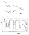
- the figure 1 represents a wireless network 1 comprising several stations 10 to 12.
- Each station 10 to 12 comprises a transmitter and a receiver comprising one or more antennas.
- station 10 communicates with stations 11 and 12 over a wireless link.
- the transmitter 2 receives as input a binary signal 20.
- the binary signal 20 is first coded by a convolutional code 29, having for example a yield equal to 1/2 with as generating polynomials (7.5) in octal notation.
- the signal is modulated by the modulator 21 according to a first modulation scheme, for example quadrature amplitude modulation nQAM with n equal to 16, 32, 64 or 256, etc.
- the modulator 21 may also implement a phase shift keying scheme, for example of the nPSK type, or any modulation.
- the modulated symbols 22 are then coded by the space-time coder 23 to form an STBC code word 24.
- the STBC code is, for example, the Golden Code as described in the document "The Golden Code: A 2 x 2 Full-Rate Space-Time Code with Non-Vanishing Determinants” (J.-C. Belfiore, G. Rekaya, E. Viterbo, IEEE Transactions on Information Theory, No. 51, No. 4, pages 1432-1436, April 2005 ).
- the STBC code can also be a code as described in the document "Space-Time Block Codes from Orthogonal Designs” (V.Tarokh, H. Jafarkhani and RA Calderbank, IEEE Transactions on Information Theory, 45, pages 1456 to 1467, July 1999 ).
- the STBC code is thus based on a complex matrix of dimension Ntx * N, where Ntx is the number of transmit antennas and N is the time length of the STBC code.
- the space / time coding can be based on a block code.
- the space / time coding is a spatial multiplexing.
- the modulated symbols are sent directly to the transmitting antennas.
- the generated code word 24 is then converted from the time domain to the frequency domain and distributed on the Ntx transmit antennas.
- Each dedicated signal 26 1 at 26 Ntx is then modulated by an OFDM modulator 27 1 at 27 Ntx , and then transmitted on the corresponding transmitting antenna 28 1 at 28 Ntx , possibly after filtering, frequency transposition and amplification (typical for a radiofrequency signal).
- the decoding technique according to the invention is not limited to the reception of a signal emitted by a transmitter as illustrated in FIG. figure 2 .
- the OFDM multicarrier modulation by any other single carrier or multicarrier modulation, such as advanced OFDM, implementing filtering by a prototype function as the IOTA function (in English "Isotropic Orthogonal Transform Algorithm").
- the time / frequency converter 25 and the OFDM modulators 27 1 to 27 Ntx are replaced by at least two single carrier modulators each associated with an antenna, in the context of a MIMO system.
- a receiver 3 when receiving a signal.
- Such a receiver 3 can notably be integrated in stations 10 to 12.
- the receiver 3 receives a signal y emitted by the transmitter 2 in a wireless channel.
- a channel is usually noisy. It is a Gaussian additive white noise (AWGN) channel, fading.
- AWGN Gaussian additive white noise
- the signal emitted by the transmitter 2 can also be affected by multipath echoes and / or the Doppler effect.
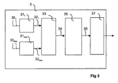
- the receiver 3 implements a treatment that is the reverse of the processing implemented in transmission.
- the OFDM demodulators 31 1 to 31 Nrx are replaced by corresponding single-carrier demodulators.
- the receiver 3 comprises Nrx receiving antennas 30 1 to 30 Nrx .
- the received signal can be represented by a matrix of size Nrx ⁇ N , or equivalently by a vector R of size ( Nrx ⁇ N ) ⁇ 1, where N is, for example, equal to 2 and represents the time and / or frequency range occupied by the space / time code.
- the space / time coding matrix C is a real matrix having a dimension (2 Ntx ⁇ N ) ⁇ 2 Q.
- a bleaching filter can be implemented in front of the space / time decoder 35.
- the variable ⁇ 2 then represents the variance of the resulting bleached noise.
- the battery decoding algorithm according to the invention can be implemented during the space / time decoding step 35. It is then considered that the space / time decoder is a battery decoder, which makes it possible to carry out a decoding ML of the coded signal.
- This decoder provides one or more candidate signals in the form of paths stored in a second stack.
- the STBC decoder 35 then provides the path obtained, or the likelihood probabilities obtained at the demodulator / decoder 37.
- the demodulator / decoder 37 is for example a flexible Viterbi decoder, implementing inverse operations to the modulation and convolutional coding steps 29 and 29.
- This demodulator / decoder 37 provides an estimate of said data signal, taking account of said path or paths stored in said second stack. This estimate can be binary or probabilistic, depending on the number of iterations implemented.
- the transmission chain does not include convolutional encoding, a single iteration is sufficient to decode the message, and the first path found provides a binary estimate of the sent signal.
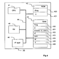
- the word "register" used in the description may correspond to a zone of small capacity (a few bits) or to a very large area (for example a whole program or a large quantity of data received or decoded).
- the algorithms for implementing the method according to this embodiment of the invention can be stored in the register 420.
- the processor CPU 41 downloads the program 420 into the RAM memory and executes the instructions corresponding.
- the data stored in the register 432 comprise, for a node of the decoding tree, the cost associated with this node, the path from the root to this node, and possibly the dimension of this node, that is, to say its depth in the tree.
- the cost associated with a current node is defined by the Euclidean distance between the received signal, and the path between the root node and the current node.
- the decoding technique according to the invention can be implemented according to a purely hardware configuration (for example in one or more integrated circuits of the FPGA, ASIC or VLSI type with the corresponding memory) or according to a configuration using both VLSI and DSP.
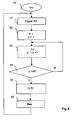
- the figure 5 illustrates more precisely the various steps implemented by the decoding method according to a particular embodiment of the invention. According to this embodiment, it is considered that several iterations are implemented, each making it possible to determine a path between a root node and a leaf node of the tree, corresponding to a potential transmitted signal.
- the decoder delivers a soft decision (in English "soft"), that is to say a probabilistic estimation of a transmitted symbol.
- the various parameters of the method are initialized.
- the counter p is set to zero.
- the decoder waits to receive a signal, derived for example from the time / frequency converter 33.
- the decoder implements a first stack decoding iteration 52. During this first iteration, the best path between the root node of the tree and a sheet is stored in the second stack.
- This first iteration can implement a conventional stack decoding algorithm. Advantageously, it implements a reduction in the number of generated child nodes by selecting only the child nodes belonging to a predetermined interval.
- the decoder implements a second stack decoding iteration 53.
- the best path between the root node of the tree and a new sheet is stored in the second stack.
- This new iteration 53 is thus based on a reduced tree excluding the previously stored paths in the second stack.
- the second iteration applies a stack decoding technique to the tree used by the first stack decoding iteration, excluding the path obtained during the first iteration.
- the maximum number of iterations is equal to the number of leaf nodes in the decoding tree.
- each path obtained during an iteration being stored in the second stack the number of iterations can be limited. by the size of the second stack.
- the decoder implements a new stack decoding iteration 53, and increments the iteration counter by one unit.
- the jth cell decoding iteration is applied to the received signal excluding the one or more determined path (s) in the or (j-1) preceding iterations of the decoding cell.
- the path obtained during a first iteration is the path defined by the bits [1011]
- the path obtained during a second iteration is the path defined by the bits [1111]
- we will assign a lower likelihood probability to the second bit which is equal to 0 according to the path defined by the first iteration, and equal to 1 according to the path defined by the second iteration.
- there , H P b i 0
- test steps 54 and the determination of the likelihood probabilities 55 are for example carried out by a DSP and / or by a VLSI (for example of the ASIC or FPGA type).
- the likelihood probabilities assigned to the different bits are transmitted to the demodulator / decoder 37. In this way, it is possible to determine an estimation of the data signal, taking into account the different paths stored in the second stack.
- the initialization step 51 can be repeated.
- Each space / time code word is thus obtained by a matrix multiplication CS.
- the coding of the incoming signal S can be represented by multiplications of complex matrices or by real matrices in which the real and imaginary parts are coded separately.
- the coding scheme described in the document " Space-Time block coding: A simple transmitter diversity technique for wireless communications " previously cited can only be represented with real notations.
- each of S 'components is subjected to amplitude pulse modulation (PAM).
- PAM amplitude pulse modulation
- the sequential decoding algorithms advantageously use a triangular matrix as a base. Therefore, it is preferable to perform a decomposition of the fading matrix G ', also called equivalent channel matrix (taking into account the channel matrix and the space / time coding matrix).
- the triangular matrix U then corresponds to the new base used by the sequential decoding algorithm.
- the time / frequency dimension N is replaced by a time dimension if a single carrier modulation is used.
- the decoder can build a decoding tree and find a good estimate of the transmitted signal S.
- the received signal is projected in the triangular matrix U determined in the previous step. This projection first multiplies the received signal R 'by G' t and then by the inverse of U t .
- the child nodes of a current node are first determined (61).
- the current node corresponds to the root node.
- Each node is associated with a cost (or metric), a path, and possibly a dimension (or depth).
- the dimension is the number of levels between the node in question and the root, depth of the tree.
- the metric of a node corresponds to the Euclidean distance (or, alternatively, to a distance function such as, for example, the square of the distance) between the received signals and the path between the root node and the node considered.
- the costs of the child nodes belonging to a predetermined interval are calculated.
- the cost associated with a child node is equal to the sum of the cost of its parent node and the contribution of the path between its parent node and itself (Euclidean distance between the received signal and the path relative to the transition between the parent node and the considered child node). This embodiment allows decoding in the ML direction.
- a bias (or a multiple of a fixed bias designated by b ) is subtracted from the cost associated with the child node.
- the cost associated with a child node with a dimension dim has a total bias equal to the dimension dim multiplied by b .
- the bias is chosen according to a desired binary error rate (BER), in order to obtain a good signal-to-noise ratio (SNR) while maintaining a reasonable complexity.
- BER binary error rate
- SNR signal-to-noise ratio
- the data relating to the child nodes are stored in a first stack.
- the current node is then removed in the first stack during a step 63.
- a new current node is selected in the first stack taking into account the associated cost. According to the embodiment described, one chooses the node which has the lowest cost.
- the node selected in step 64 is the first node of the stack.
- the decoder checks whether the new current node is a leaf node. If this is not the case, we return to step 61 of selecting at least one child node for the new current node.
- the new current node is a leaf node, it memorizes in a second stack, during a step 66, the path between the root node of the tree, and the leaf node. In other words, a candidate signal is selected and stored in memory. This leaf node is then deleted from the first stack.
- the iteration counter p is then updated during a step 67. It is recalled that p is equal to 1 for the first iteration (52), then incremented by one unit during the following iterations (53).
- the considered child nodes belong to a predetermined interval, which is to say that a child node is taken into consideration only when its metric is equal to or less than a threshold designated by C. In this way, one stores in the first stack only the data relating to the son nodes having a cost lower than the threshold C.
- This threshold corresponds for example to the radius of a sphere centered on the received signal, and the paths traveled in the tree correspond to the points of the network lying inside this sphere.
- This threshold value C can be set arbitrarily.
- the value of the threshold C can also be defined dynamically, depending on one or more characteristics of the transmission channel.
- k can depend in particular on the depth inside the tree. Thus, more child nodes can be generated for smaller dimensions and fewer child nodes for higher dimensions. For example, if one seeks to decode four complex symbols of 4-QAM modulation, a tree of depth equal to 8, in which each node has two son, can be used. For the first four dimensions, we can determine each time the two possible son nodes, then for the last four dimensions, we can generate only one of the two son nodes.
- threshold C is very large, so as to cover as many paths as possible.
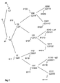
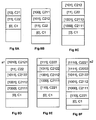
- the first stack then contains the data associated with the nodes 80 and 81.
- the new current node selected in step 64 is node 81.
- the new current node selected in step 64 is the node 810.
- the first stack is ordered by positioning at the top of the stack the node presenting the lowest cost, and assuming that the metric C22 is less than the metric C1 (C21 ⁇ C22 ⁇ C1), then the first stack contains the node 810 (top of the stack), then the node 811 and finally the node 80 (base of the pile). The contents of the first stack at this moment is illustrated in figure 8A .
- the new node current selected in step 64 is the node 8100. If the metric C212 is less than the metric C22 (C211 ⁇ C212 ⁇ C22 ⁇ C1), then the first stack contains the node 8100 (top of the stack), then node 8101, then node 811 and finally node 80 (base of the stack). The contents of the first stack at this moment is illustrated in Figure 8B .
- the new current node selected in step 64 is node 8101.
- the first stack contains the node 8101 (top of the stack ), then the node 811, then the node 81001, then the node 81000, and finally the node 80 (base of the stack).
- the contents of the first stack at this moment is illustrated in Figure 8C .
- the new current node selected in step 64 is node 81010.
- the first stack then contains the node 81010 (top of the stack), then the node 811, then the node 81011, then the node 81001, then the node 81000 and finally the node 80 (base of the stack).
- the contents of the first stack at this moment is illustrated in figure 8D .
- the path between the root of the tree and the node 81010 is stored in a second stack.
- the second stack contains the path C2121, corresponding to the bits [1010].
- the first battery decoding iteration 52 is complete.
- the second stack decoding iteration 53 is implemented. This second iteration is applied to the tree by excluding the first candidate solution a1, that is to say by deleting the leaf node 81010 to determine a new path between the root of the tree and a leaf.
- a new current node is selected, having the lowest associated cost. This is node 811.
- the new current node selected in step 64 is the node 8111.
- the first stack then contains the node 8111 (top of the stack), then the node 81011, then the node 81001, then the node 81000, then the node 8110, and finally the node 80 (base of the pile).
- the contents of the first stack at this moment is illustrated in figure 8E .
- the new current node selected in step 64 is the node 81110.
- the first stack then contains the node 81110 (top of the stack), then the node 81111, then the node 81011, then the node 81001, then the node 81000, then the node 8110, and finally the node 80 (base of the pile ).
- the contents of the first stack at this moment is illustrated in figure 8F .
- the path between the root of the tree and the node 81110 is stored in the second stack.
- This is a second candidate signal, noted a2
- the second stack contains, in addition to the path C2121, corresponding to the bits [1010], determined during the first iteration, the path C2221, corresponding to the bits [1110 ].
- the second stack decoding iteration 53 is complete.
- Figures 8A to 8F illustrate the contents of the first stack at different stages of the decoding step.
- the data of the nodes are stored in the first stack in descending order of the metrics associated with the nodes.
- the data of a node corresponding to the lowest cost are at the top of the stack
- the data of a node corresponding to the highest cost are at the bottom of the stack.
- the sorting of the data during the storage step can be implemented by comparing the data of the newly stored nodes with the costs of the nodes already stored. It is not necessary to compare the costs of the nodes already stored in the first stack with each other. This method corresponds to insertion sorting. In this way, during the step of selecting a new current node, simply select the node at the top of the stack.
- the second stack which includes a list of candidate paths, is ordered by construction. During the step of determining a probabilistic estimation of the data signal, it is possible to choose to grant greater confidence to the paths located at the top of the second stack. Thus, only the most reliable paths of the second stack can be used to calculate the likelihood probabilities.
- a transmission system comprising a receiver and a plurality of transmitters, each comprising a single antenna, each transmitter being able to be identified by a multiple access scheme (for example of the CDMA type). Access ", in French” code division multiple access "),” OFDM flash ", ). Multiple users therefore share the same transmission resource to transmit data to the receiver.
- the problem of decoding comprises an estimation of a transmitted discrete input vector, based on an observation of the received signal, corresponding to the transmitted vector disturbed by the channel.
- the input vector consists of the real and imaginary components of the set of symbols transmitted by Q users in a given time and / or frequency region, depending on the schema of multiple access.
- the region corresponds to the time duration of the spreading sequences.
- the value Q here corresponds to the number of transmitters used, in the same way that Q indicates the number of symbols per spatio-temporal code word in the example of application to the multi-antenna systems previously discussed.
- the observation of the signal is composed by the set of responses associated with the signals transmitted by each transmitter.
- the linear distortion of the transmitted signals can be represented by a matrix composed of the set of equivalent channel matrices between the transmitters Q and the receiver, taking into account the multiple access scheme. For example, in CDMA, this linear distortion corresponds to a combination between the different channel matrices and the correlation matrix of the spreading code subset.
- the additive noise is the additive Gaussian thermal white noise at the receiver and its amplitude follows a law in ⁇ 2 .
- the figure 9 represents a multi-user detection according to a specific embodiment of the invention. This detection is implemented in a receiver that receives data from Q transmitters using for example code division multiple access (CDMA).
- CDMA code division multiple access
- Decoding begins with an initialization step 90 in which different process parameters are set to their initial value (s).
- the receiver waits to receive a signal from the filters adapted to the CDMA sequences used.
- An estimate of the different transmission channels between the transmitters Q and the receiver is then implemented during a step 92. For example, this estimate is based on the pilot sequences used specifically by each transmitter.
- the receiver can thus deduce the value of ⁇ using, for example, pilot sequences. This step may be performed after each channel estimate, or each time a signal corresponding to a single transmitted block is received.
- the receiver executes a preprocessing step 93, during which the matrix composed of the set of equivalent channel matrices between the transmitters Q and the receiver, taking into account the multiple access scheme, is replaced by the matrix equivalent channel G '.
- the receiver performs a battery decoding during a step 94, implementing at least one stack decoding iteration.
- the receiver implements steps 52 to 56 previously described in connection with the figure 5 , in order to obtain a probabilistic estimation, the candidate signal of the figure 5 being replaced by a set of signals transmitted by the Q transmitters.
- certain transmitters and / or the receiver can use several antennas.
- the signal transmitted between the different transmitters and the receiver can also be single carrier or multicarrier.
- the invention can be used regardless of the type of transmission (point-to-point, multipoint to point, wireless local area networks, mobile networks, digital broadcasting, satellite communication, ).
- the receiver illustrated in figure 3 then comprises elements adapted to such an application (such as a MAC layer interface, a demodulator, or any other conventional element used in digital communications).
- the invention is also well adapted to the reception of television signals, emitted for example according to the DVB ("Digital Video Broadcasting"), DVB-T (terrestrial), DVB-S (satellite), or DVB-H (mobile) standard. ), etc.
- the invention can be used for the decoding of signals transmitted over a wireless link with high spectral efficiency (such as a MIMO system and / or nQAM modulation), and, in particular, in a high-speed transmission.
- a wireless link with high spectral efficiency such as a MIMO system and / or nQAM modulation
- the invention is not limited to multi-antenna or multi-user applications, and can for example be used in an application combining the MIMO decoding and multi-user detection techniques.
Landscapes
- Engineering & Computer Science (AREA)
- Artificial Intelligence (AREA)
- Computer Networks & Wireless Communication (AREA)
- Signal Processing (AREA)
- Error Detection And Correction (AREA)
- Radio Transmission System (AREA)
Description
Le domaine de l'invention est celui des communications numériques.The field of the invention is that of digital communications.
Plus précisément, l'invention concerne la réception et le décodage de signaux numériques, reçus par exemple dans le cadre d'une transmission multi-antennes ou multi-utilisateurs.More specifically, the invention relates to the reception and decoding of digital signals, received for example in the context of a multi-antenna or multi-user transmission.
Un problème important dans le domaine des communications numériques est celui du décodage des signaux reçus.An important problem in the field of digital communications is the decoding of the received signals.
En effet, après émission, les signaux sont véhiculés dans un canal de transmission qui peut être plus ou moins bruité. Les signaux reçus sont donc plus ou moins perturbés, et il peut être nécessaire de mettre en oeuvre un traitement spécifique pour les décoder correctement.Indeed, after transmission, the signals are conveyed in a transmission channel which can be more or less noisy. The signals received are therefore more or less disturbed, and it may be necessary to implement a specific processing to decode them correctly.
Afin d'obtenir de bonnes performances de décodage, il est souhaitable d'utiliser une technique de décodage optimale au sens du maximum de vraisemblance (ou ML, en anglais « Maximum Likelihood »). Un décodeur optimal permet d'estimer le signal candidat le plus probable, étant donné le signal observé reçu.In order to obtain good decoding performance, it is desirable to use an optimal decoding technique in the maximum likelihood (or ML) sense. An optimal decoder makes it possible to estimate the most likely candidate signal, given the observed signal received.
Pour effectuer un décodage optimal au sens ML, on dénombre classiquement tous les signaux transmis potentiels (encore appelés signaux candidats), et on sélectionne le signal le plus vraisemblable. Par exemple, le critère de sélection consiste à calculer une distance euclidienne entre le signal observé reçu et les signaux candidats.In order to perform an optimal decoding in the ML direction, all the potential transmitted signals (also called candidate signals) are conventionally counted, and the most likely signal is selected. For example, the selection criterion consists in calculating a Euclidean distance between the received observed signal and the candidate signals.
Malheureusement, un tel dénombrement exhaustif est coûteux en temps et en ressources, et peut difficilement être mis en oeuvre dans des applications en temps réel. En effet, le nombre de candidats, et par conséquent la complexité du décodeur, augmentent de façon exponentielle en fonction de la longueur du signal numérique. Par exemple, un signal numérique présentant une longueur de 10 bits peut prendre 210 = 1024 valeurs différentes, et toutes ces valeurs doivent être dénombrées dans le décodage ML classique.Unfortunately, such exhaustive enumeration is costly in time and resources, and can hardly be implemented in real-time applications. Indeed, the number of candidates, and therefore the complexity of the decoder, increase exponentially as a function of the length of the digital signal. For example, a digital signal having a length of 10 bits can take 2 10 = 1024 different values, and all these values should be counted in the conventional ML decoding.
Afin de pallier cet inconvénient de dénombrement exhaustif, d'autres techniques de décodage sont apparues, comme les techniques de décodage séquentiel. Ces techniques utilisent une représentation arborescente du problème, dans laquelle chaque chemin du noeud racine à un noeud feuille est un signal transmis potentiel.To overcome this drawback of exhaustive enumeration, other decoding techniques have emerged, such as sequential decoding techniques. These techniques use a tree representation of the problem, in which each path from the root node to a leaf node is a potential transmitted signal.
En effet, on rappelle qu'une structure de données peut être représentée sous la forme d'une structure arborescente présentant un ensemble de noeuds. Pour une constellation 2 n QAM (en anglais « Quadrature Amplitude Modulation »), n branches partent d'un noeud de l'arbre. Le premier noeud de l'arbre est appelé noeud racine. Chaque noeud d'un arbre peut avoir zéro, un ou plusieurs noeuds fils, qui sont situés sous lui dans l'arbre. Un noeud qui ne présente aucun noeud fils est appelé noeud feuille. Il correspond au niveau le plus bas dans l'arbre. Un noeud a au plus un noeud parent, situé au-dessus de lui dans l'arbre. Le noeud racine étant le noeud le plus élevé dans l'arbre, il n'a pas de noeud parent. La profondeur (ou dimension) d'un noeud est la longueur du chemin de ce noeud à sa racine. Le noeud racine est le noeud sur lequel des opérations sur l'arbre commencent ordinairement. Tous les autres noeuds peuvent être atteints à partir de celui-ci en suivant des liens.Indeed, it is recalled that a data structure can be represented in the form of a tree structure having a set of nodes. For a 2 n QAM constellation (in English "Quadrature Amplitude Modulation"), n branches start from a node of the tree. The first node of the tree is called the root node. Each node of a tree can have zero, one or more child nodes, which are located under it in the tree. A node that does not have any child nodes is called a leaf node. It corresponds to the lowest level in the tree. A node has at most one parent node, located above it in the tree. Since the root node is the highest node in the tree, it does not have a parent node. The depth (or dimension) of a node is the path length of that node at its root. The root node is the node on which operations on the tree usually start. All other nodes can be reached from it by following links.
A partir de cette représentation arborescente, le décodage séquentiel dénombre un nombre réduit de signaux candidats par rapport à ce que ferait un décodeur optimal au sens ML. Par exemple, avec un nombre de symboles Q égal à 8 et en utilisant une constellation 16 QAM, un décodeur ML classique dénombre 168 signaux candidats pour décoder un mot de code espace/temps, alors qu'un décodeur à pile ne dénombre que très peu de ceux-ci. Pour ce faire, les techniques de décodage séquentiel tiennent compte d'une contrainte de coûts (ou métrique), de façon à déterminer un unique chemin candidat à l'intérieur d'un arbre de décodage. Classiquement, le coût associé à un noeud courant est défini par la distance euclidienne entre le signal reçu, et le chemin entre le noeud racine et le noeud courant.From this tree representation, the sequential decoding counts a reduced number of candidate signals compared to what would make an optimal decoder ML. For example, with a number of Q symbols equal to 8 and using a 16 QAM constellation, a conventional ML decoder counts 16 8 candidate signals to decode a space / time code word, whereas a battery decoder only counts very few of these. To do this, the sequential decoding techniques take into account a cost constraint (or metric), so as to determine a single candidate path within a decoding tree. Conventionally, the cost associated with a current node is defined by the Euclidean distance between the received signal, and the path between the root node and the current node.
Le décodage séquentiel peut être mis en oeuvre dans un décodeur à pile (en anglais « stack decoder »), délivrant une estimation dure (en anglais « hard ») du signal émis, c'est-à-dire une estimation binaire, tel que décrit notamment dans les documents
Si aucune contrainte de coût n'est fixée, un tel décodeur présente des performances optimales au sens ML. En revanche, si une contrainte est fixée, afin de limiter le temps de recherche dans l'arbre de décodage par exemple, les performances obtenues sont sous-optimales, c'est-à-dire inférieures aux performances obtenues par la mise en oeuvre d'une technique de type ML.If no cost constraint is set, such a decoder has optimal performance in the ML direction. On the other hand, if a constraint is fixed, in order to limit the search time in the decoding tree for example, the obtained performances are sub-optimal, that is to say lower than the performances obtained by the implementation of a ML type technique.
Une telle technique de décodage sous-optimale est donc moins complexe, et nécessite moins de ressources qu'une technique optimale, mais présente de moins bonnes performances.Such suboptimal decoding technique is therefore less complex, and requires fewer resources than an optimal technique, but has poorer performance.
Il a également été proposé des décodeurs séquentiels délivrant une estimation souple (en anglais « soft ») du signal émis, c'est-à-dire une estimation probabiliste, comme dans le document
Malheureusement, ces décodeurs séquentiels à décision souple présentent une complexité importante. De plus, la liste de chemins potentiels déterminée à partir de l'arbre de décodage, et à partir de laquelle on détermine une estimation probabiliste du signal émis, n'est pas optimisée.Unfortunately, these soft-decision sequential decoders have an important complexity. In addition, the list of potential paths determined from the decoding tree, and from which a probabilistic estimate of the transmitted signal is determined, is not optimized.
L'invention propose une solution nouvelle pour le décodage d'un signal, sous la forme d'un procédé de décodage d'un signal reçu, correspondant à un signal de données émis véhiculé par l'intermédiaire d'un canal de transmission.The invention proposes a novel solution for decoding a signal, in the form of a method for decoding a received signal, corresponding to a transmitted data signal transmitted via a transmission channel.
On considère que le procédé met en oeuvre une construction progressive d'un arbre de décodage, dans lequel un noeud correspond à une composante d'un symbole dudit signal de données, et est associé à un coût.It is considered that the method implements a progressive construction of a decoding tree, in which a node corresponds to a component of a symbol of said data signal, and is associated with a cost.
Selon l'invention, la construction de l'arbre de décodage met en oeuvre au moins deux itérations des étapes suivantes, pour un noeud courant de l'arbre mémorisé dans une première pile, chaque itération permettant de mémoriser dans une deuxième pile un chemin entre le noeud racine de l'arbre et un noeud feuille :
- sélection d'au moins un noeud fils dudit noeud courant appartenant à un intervalle de sélection prédéterminé, si au moins un tel noeud existe ;
- mémorisation dans ladite première pile des noeuds fils sélectionnés et des coûts associés ;
- suppression, dans ladite première pile, dudit noeud courant ;
- sélection dans ladite première pile, d'un nouveau noeud courant, en tenant compte du coût associé ; et
- si ledit nouveau noeud courant est un noeud feuille, qui ne possède aucun noeud fils, mémorisation du chemin entre le premier noeud dudit arbre, dit noeud racine, et ledit noeud feuille, dans la deuxième pile, et suppression du noeud feuille dans la première pile ;
- sinon, retour à l'étape de sélection d'au moins un noeud fils pour ledit nouveau noeud courant.
- selecting at least one child node of said current node belonging to a predetermined selection interval, if at least one such node exists;
- storing in said first stack selected child nodes and associated costs;
- deleting, in said first stack, said current node;
- selecting in said first stack, a new current node, taking into account the associated cost; and
- if said new current node is a leaf node, which has no child node, storing the path between the first node of said tree, said root node, and said leaf node, in the second stack, and deleting the leaf node in the first stack ;
- otherwise, return to the step of selecting at least one child node for said new current node.
Le procédé selon l'invention affecte également une probabilité de vraisemblance aux bits d'au moins un symbole du signal de données, en tenant compte des chemins mémorisés dans la deuxième pile, et comprend une étape de détermination d'une estimation probabiliste du signal de données (monoporteuse ou multiporteuse), en tenant compte du ou des chemins mémorisés dans la deuxième pile et des probabilités de vraisemblance.The method according to the invention also affects a likelihood probability at the bits of at least one symbol of the data signal, taking into account the paths stored in the second stack, and comprises a step of determining a probabilistic estimation of the signal of data (single-carrier or multi-carrier), taking into account the path (s) stored in the second stack and likelihood probabilities.
L'invention propose ainsi une solution nouvelle pour le décodage d'un signal reçu, basée sur un algorithme de type « stack » (décodage à pile).The invention thus proposes a new solution for the decoding of a received signal, based on on an algorithm of the type "stack" (decoding with stack).
Plus précisément, l'invention propose une modification du décodage à pile permettant d'avoir une sortie souple, c'est-à-dire une estimation probabiliste du signal émis, tout en diminuant la complexité de décodage. On note que si une seule itération est réalisée, délivrant un unique chemin entre le noeud racine de l'arbre et un noeud feuille, les performances optimales au sens ML sont obtenues.More precisely, the invention proposes a modification of the stack decoding allowing a flexible output, that is to say a probabilistic estimation of the transmitted signal, while decreasing the decoding complexity. Note that if a single iteration is performed, delivering a single path between the root node of the tree and a leaf node, optimal performance in the ML direction are obtained.
Pour ce faire, l'invention propose de limiter le nombre de noeuds développés dans l'arbre de décodage, en ne générant que les noeuds appartenant à un intervalle de sélection prédéterminé. On calcule ainsi et on mémorise dans la première pile les coûts associés aux noeuds appartenant à l'intervalle de sélection.To do this, the invention proposes to limit the number of nodes developed in the decoding tree, by generating only the nodes belonging to a predetermined selection interval. The costs associated with the nodes belonging to the selection interval are thus calculated and stored in the first stack.
Il est ainsi possible de ne conserver que les noeuds présentant un coût inférieur ou égal à un seuil C prédéterminé.It is thus possible to keep only the nodes having a cost less than or equal to a predetermined threshold C.
Par exemple, ce seuil C correspond au rayon d'une sphère centrée sur le signal reçu. Les chemins pouvant être parcourus dans l'arbre correspondent alors aux vecteurs de symboles (encore appelés points du réseau en référence au réseau de points) se trouvant à l'intérieur de cette sphère.For example, this threshold C corresponds to the radius of a sphere centered on the received signal. The paths that can be traversed in the tree then correspond to the vectors of symbols (also called points of the network in reference to the network of points) being inside this sphere.
Selon cet exemple, l'intervalle de sélection est déterminé pour chaque composante d'un symbole du signal de données à partir d'un premier intervalle déterminé à partir de la sphère de rayon C centrée sur ledit signal reçu, et d'un deuxième intervalle déterminé à partir de la constellation des symboles. L'intervalle de sélection est calculé pour chaque noeud (composante) au fur et à mesure de la construction de l'arbre de décodage.According to this example, the selection interval is determined for each component of a symbol of the data signal from a first interval determined from the sphere of radius C centered on said received signal, and a second interval determined from the constellation of symbols. The selection interval is calculated for each node (component) as the decoding tree is constructed.
En particulier, le rayon de la sphère peut être choisi arbitrairement ou en fonction d'au moins une caractéristique du canal de transmission.In particular, the radius of the sphere may be chosen arbitrarily or as a function of at least one characteristic of the transmission channel.
On sélectionne ainsi pour un noeud courant l'ensemble des noeuds fils appartenant à l'intervalle de sélection, et on construit à partir de ces noeuds fils sélectionnés un chemin entre le noeud racine et un noeud feuille de l'arbre, correspondant à un signal transmis potentiel.Thus, for a current node, all the child nodes belonging to the selection interval are selected, and a path between the root node and a leaf node of the tree, corresponding to a signal, is constructed from these selected child nodes. transmitted potential.
Chaque chemin ainsi construit au cours d'une itération de décodage à pile est mémorisé dans une deuxième pile. Il est ainsi possible de déterminer une liste de signaux transmis potentiels, en mettant en oeuvre plusieurs itérations, permettant chacune de mémoriser un nouveau chemin dans la deuxième pile. Une estimation probabiliste du signal émis est ainsi obtenue. Par exemple, une telle sortie probabiliste est souhaitable si un codage de canal est utilisé.Each path thus constructed during a stack decoding iteration is stored in a second stack. It is thus possible to determine a list of potential transmitted signals, by implementing several iterations, each making it possible to memorize a new path in the second stack. A probabilistic estimation of the emitted signal is thus obtained. For example, such a probabilistic output is desirable if channel coding is used.
Selon l'invention, on affecte également une probabilité de vraisemblance aux bits d'au moins un symbole du signal de données en tenant compte des chemins mémorisés dans la deuxième pile. L'estimation du signal de données est alors une estimation probabiliste, ou souple, tenant compte des probabilités de vraisemblance.According to the invention, a likelihood probability is also assigned to the bits of at least one symbol of the data signal taking into account the paths stored in the second stack. The estimation of the data signal is then a probabilistic, or flexible, estimate taking into account likelihood probabilities.
On note que le critère d'arrêt des itérations peut être défini de différentes manières.It is noted that the criteria for stopping the iterations can be defined in different ways.
Par exemple, les itérations sont mises en oeuvre tant que la deuxième pile n'est pas remplie. Ainsi, les itérations sont mises en oeuvre tant que le coût associé audit noeud courant est inférieur ou égal à un seuil prédéterminé.For example, the iterations are implemented as long as the second stack is not filled. Thus, the iterations are implemented as long as the cost associated with said current node is less than or equal to a predetermined threshold.
Selon un autre exemple, si une estimation dure du signal est suffisante, la taille de la pile peut être limitée de façon à ne stocker qu'un seul chemin, et éventuellement le coût associé à ce chemin.In another example, if a hard estimate of the signal is sufficient, the size of the stack can be limited so as to store only one path, and possibly the cost associated with this path.
En effet, selon une autre variante de réalisation, le procédé selon l'invention peut mettre en oeuvre une seule itération, délivrant une estimation dure du signal émis.Indeed, according to another alternative embodiment, the method according to the invention can implement a single iteration, delivering a hard estimate of the transmitted signal.
Ainsi, si une seule itération est mise en oeuvre, un unique chemin entre le noeud racine et un noeud feuille est mémorisé dans la deuxième pile, et l'estimation du signal de données est une estimation binaire.Thus, if a single iteration is implemented, a single path between the root node and a leaf node is stored in the second stack, and the estimate of the data signal is a binary estimate.
Selon un mode de réalisation particulier de l'invention, les itérations comprennent une étape d'ordonnancement de la première pile, préalablement à l'étape de sélection d'un nouveau noeud courant, ordonnant lesdits noeuds en fonction du coût associé, le noeud présentant le coût le plus faible étant situé en premier dans la première pile.According to a particular embodiment of the invention, the iterations comprise a step of scheduling the first stack, prior to the step of selecting a new current node, ordering said nodes according to the associated cost, the node presenting the lowest cost being located first in the first stack.
De cette façon, lors de l'étape de sélection d'un nouveau noeud courant, on sélectionne le premier noeud dans la première pile.In this way, during the step of selecting a new current node, the first node is selected in the first stack.
On rappelle que, classiquement, le coût associé à un noeud est défini par la distance euclidienne (ou une fonction de la distance) entre le signal reçu et le chemin entre le noeud racine et ledit noeud.Recall that, conventionally, the cost associated with a node is defined by the Euclidean distance (or a function of the distance) between the received signal and the path between the root node and said node.
Selon une variante de réalisation, les itérations comprennent une étape de détermination des coûts des noeuds fils appartenant à l'intervalle de sélection, et de soustraction d'un biais au coût associé au noeud fils, préalablement à ladite étape de mémorisation.According to an alternative embodiment, the iterations comprise a step of determining the costs of the child nodes belonging to the selection interval, and of subtracting a cost bias associated with the child node, prior to said storage step.
De cette façon, on limite encore la complexité de décodage, en privilégiant les chemins les plus avancés (c'est-à-dire les noeuds les plus profonds) dans l'arbre. Cette variante permet une réduction de la complexité, mais fournit des performances sous-optimales.In this way, the decoding complexity is further limited by focusing on the more advanced paths (i.e. the deeper nodes) in the tree. This variant reduces complexity, but provides suboptimal performance.
Selon un premier exemple d'application, le procédé selon l'invention est mis en oeuvre dans un système multi-antennes. Ainsi, le signal de données est émis sur au moins une antenne d'émission et reçu sur au moins une antenne de réception.According to a first example of application, the method according to the invention is implemented in a multi-antenna system. Thus, the data signal is transmitted on at least one transmitting antenna and received on at least one receiving antenna.
Par exemple, le signal de données a subi un codage espace-temps avant émission, et la construction de l'arbre est mise en oeuvre lors d'une étape de décodage espace-temps.For example, the data signal has undergone space-time coding before transmission, and the construction of the tree is implemented during a space-time decoding step.
Selon un deuxième exemple d'application, le procédé selon l'invention est mis en oeuvre dans un système multi-utilisateurs. Ainsi, le signal de données est émis par au moins deux utilisateurs distincts.According to a second example of application, the method according to the invention is implemented in a multi-user system. Thus, the data signal is transmitted by at least two distinct users.
L'invention concerne également un produit programme d'ordinateur téléchargeable depuis un réseau de communication et/ou enregistré sur un support lisible par ordinateur et/ou exécutable par un processeur, comprenant des instructions de code de programme pour la mise en oeuvre du procédé de décodage tel que décrit précédemment.The invention also relates to a computer program product downloadable from a communication network and / or recorded on a computer readable medium and / or executable by a processor, comprising program code instructions for implementing the method of decoding as described above.
Un autre mode de réalisation de l'invention concerne encore un dispositif de décodage d'un signal reçu, correspondant à un signal de données émis véhiculé par l'intermédiaire d'un canal de transmission,
comprenant des moyens pour la construction progressive d'un arbre de décodage, dans lequel un noeud correspond à une composante d'un symbole dudit signal de données, et est associé à un coût,
et une première pile dans laquelle est mémorisée un noeud courant dudit arbre.Another embodiment of the invention also relates to a device for decoding a received signal, corresponding to a transmitted data signal conveyed via a transmission channel.
comprising means for the progressive construction of a decoding tree, wherein a node corresponds to a component of a symbol of said data signal, and is associated with a cost,
and a first stack in which is stored a current node of said tree.
Selon ce mode de réalisation, les moyens de construction comprennent les moyens suivants, activés pour au moins deux itérations permettant chacune de mémoriser dans une deuxième pile un chemin entre le noeud racine de l'arbre et un noeud feuille :
- des moyens de sélection d'au moins un noeud fils dudit noeud courant appartenant à un intervalle de sélection prédéterminé, si au moins un tel noeud existe ;
- des moyens de mémorisation dans ladite première pile des noeuds fils sélectionnés et des coûts associés ;
- des moyens de suppression, dans ladite première pile, dudit noeud courant ;
- des moyens de sélection dans ladite première pile, d'un nouveau noeud courant, en tenant compte du coût associé ; et
- des moyens de mémorisation du chemin entre le premier noeud dudit arbre, dit noeud racine, et ledit noeud feuille, dans la deuxième pile ;
- des moyens de suppression du noeud feuille dans la première pile ;
- des moyens d'affectation d'une probabilité de vraisemblance aux bits d'au moins un symbole du signal de données, en tenant compte des chemins mémorisés dans la deuxième pile, et
- des moyens de détermination d'une estimation probabiliste du signal de données, à partir du ou des chemins mémorisés dans la deuxième pile et des probabilités de vraisemblance.
- means for selecting at least one child node of said current node belonging to a predetermined selection interval, if at least one such node exists;
- storage means in said first stack of selected child nodes and associated costs;
- suppression means, in said first stack, of said current node;
- selection means in said first stack, of a new current node, taking into account the associated cost; and
- means for storing the path between the first node of said tree, said root node, and said leaf node, in the second stack;
- means for deleting the leaf node in the first stack;
- means for assigning a probability of likelihood to the bits of at least one symbol of the data signal, taking into account the paths stored in the second stack, and
- means for determining a probabilistic estimation of the data signal from the path or paths stored in the second stack and likelihood probabilities.
Un tel dispositif de décodage est notamment adapté à mettre en oeuvre le procédé de décodage décrit précédemment. Il peut par exemple être intégré dans un récepteur d'un système MIMO ou multi-utilisateurs, comprenant une ou plusieurs antennes de réception.Such a decoding device is particularly suitable for implementing the decoding method described above. It can for example be integrated in a receiver of a system MIMO or multi-user, comprising one or more receiving antennas.
Ce dispositif pourra bien sûr comporter les différentes caractéristiques relatives au procédé de décodage selon l'invention.This device may of course include the various features relating to the decoding method according to the invention.
En particulier, ce dispositif peut être composé d'au moins un circuit appartenant au groupe comprenant :
- les FPGA (en anglais « Field programmable gate array », en français « réseau prédiffusé programmable par l'utilisateur ») ;
- les ASIC (en anglais « Application Specific Integrated Circuit », en français « circuits intégrés à application spécifique ») ;
- les VLSI (en anglais « Very Large Scale Integration », en français « intégration à très grande échelle »).
- FPGAs (in English "Field Programmable Gate Array", in English "gate array programmable by the user");
- ASICs (in English "Application Specific Integrated Circuit");
- VLSI (in English "Very Large Scale Integration").
Ainsi, la technique de décodage proposée peut être mise en oeuvre selon une configuration uniquement logicielle, uniquement matérielle (par exemple dans un ou plusieurs circuits intégrés de type FPGA, ASIC ou VLSI avec la mémoire correspondante) ou selon une configuration mixte.Thus, the proposed decoding technique can be implemented in a software-only, hardware-only configuration (for example in one or more integrated circuits of the FPGA, ASIC or VLSI type with the corresponding memory) or in a mixed configuration.
D'autres caractéristiques et avantages de l'invention apparaîtront plus clairement à la lecture de la description suivante d'un mode de réalisation particulier, donné à titre de simple exemple illustratif et non limitatif, et des dessins annexés, parmi lesquels :
- la
figure 1 illustre un réseau sans fil ; - la
figure 2 présente les principales étapes mises en oeuvre par un émetteur pour une première application de l'invention ; - la
figure 3 présente les principales étapes mises en oeuvre par un récepteur pour une première application de l'invention ; - la
figure 4 illustre un exemple d'architecture d'un décodeur mettant en oeuvre un mode de réalisation particulier de l'invention ; - la
figure 5 illustre les différentes étapes mises en oeuvre par le procédé de décodage selon un mode de réalisation particulier de l'invention ; - la
figure 6 illustre la mise en oeuvre d'une itération de décodage à pile de lafigure 5 ; - la
figure 7 présente un exemple d'arbre de décodage associé au procédé de décodage selon lafigure 5 ; - les
figures 8A à 8F illustrent le contenu de la première pile lors de la construction de l'arbre de lafigure 7 ; - la
figure 9 présente les principales étapes mises en oeuvre par un récepteur pour une deuxième application de l'invention ; - la
figure 10 illustre le principe général de l'invention.
- the
figure 1 illustrates a wireless network; - the
figure 2 presents the main steps implemented by an issuer for a first application of the invention; - the
figure 3 presents the main steps implemented by a receiver for a first application of the invention; - the
figure 4 illustrates an exemplary architecture of a decoder implementing a particular embodiment of the invention; - the
figure 5 illustrates the various steps implemented by the decoding method according to a particular embodiment of the invention; - the
figure 6 illustrates the implementation of a stack decoding iteration of thefigure 5 ; - the
figure 7 presents an example of a decoding tree associated with the decoding method according to thefigure 5 ; - the
Figures 8A to 8F illustrate the contents of the first pile when building the tree of thefigure 7 ; - the
figure 9 presents the main steps implemented by a receiver for a second application of the invention; - the
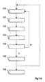
figure 10 illustrates the general principle of the invention.
Le principe général de l'invention repose sur la modification d'une technique de décodage séquentiel à pile pour réduire la complexité de décodage. Pour ce faire, on limite lors de la construction de l'arbre de décodage le nombre de fils que l'on détermine pour un noeud courant, en ne déterminant que les noeuds appartenant à un intervalle de sélection prédéfini.The general principle of the invention is based on the modification of a stacked sequential decoding technique to reduce the decoding complexity. To do this, during the construction of the decoding tree, the number of wires that are determined for a current node is limited by only determining the nodes belonging to a predefined selection interval.
En effet, on rappelle que pour la construction d'un arbre de décodage selon la technique décrite dans les documents « A fast sequential decoding algorithm using a stack » ou « A unified framework for tree search decoding : rediscovering the sequential On propose selon n branches partent de chaque noeud de l'arbre pour une constellation 2 n QAM. On propose selon l'invention de réduire le nombre de branches partant de chaque noeud, en ne générant que les noeuds fils appartenant à un intervalle de sélection prédéfini.Indeed, it is recalled that for the construction of a decoding tree according to the technique described in the documents " A fast sequential decoding algorithm using a stack " or " A unified framework for tree search decoding: rediscovering the sequential On proposes according to n branches start from each node of the tree for a 2 n QAM constellation. According to the invention, it is proposed to reduce the number of branches starting from each node, by generating only the child nodes belonging to a predefined selection interval.
Pour ce faire, selon un mode de réalisation particulier de l'invention, on combine les caractéristiques des décodeurs séquentiels et des décodeurs par sphères. On considère ainsi une sphère de rayon C, centrée sur le signal reçu. Lors de la construction progressive de l'arbre de décodage, on ne génère que les noeuds correspondants à des points dans la sphère. En d'autres termes, chaque noeud fils n'est généré et mémorisé dans une première pile que si son coût reste inférieur au rayon C.To do this, according to a particular embodiment of the invention, the characteristics of sequential decoders and spherical decoders are combined. A sphere of radius C, centered on the received signal, is thus considered. During the progressive construction of the decoding tree, only the nodes corresponding to points in the sphere are generated. In other words, each child node is generated and stored in a first stack only if its cost remains less than the radius C.
La technique classique de décodage par sphères est notamment décrite dans le document
De cette façon, le temps de recherche et le nombre de calculs pour déterminer un signal candidat sont réduits. On peut également noter que quelque soit le rayon de la sphère, les performances de l'algorithme proposé sont toujours optimales au sens ML, mais c'est la complexité de décodage qui varie. Ainsi, plus le rayon de la sphère est petit, plus l'arbre de décodage sera petit, et plus la complexité de décodage sera réduite.In this way, the search time and the number of calculations to determine a candidate signal are reduced. It can also be noted that whatever the radius of the sphere, the performances of the proposed algorithm are always optimal in the ML direction, but it is the decoding complexity that varies. Thus, the smaller the radius of the sphere, the smaller the decoding tree, and the lower the decoding complexity.
Par exemple, en utilisant les mêmes formules que celles proposées dans le document « A Universal Lattice Code Decoder for Fading and Channels », parcourant les points dans la sphère de rayon C, on obtient pour chaque composante réelle ou imaginaire d'un symbole du signal à décoder un intervalle Ii =[binf i, Bsup i ]. Pour ajouter la contrainte liée à la constellation, on considère l'intersection entre l'intervalle [C min,C max] (correspondant à la constellation moyennant un changement de variable pour se placer dans Z au lieu de 2Z, où Z est l'ensemble des entiers relatifs et 2Z l'ensemble des entiers relatifs pairs) et les intervalles Ii . Par exemple, pour une modulation 16QAM Cmin = 0 et Cmax = 3. L'intervalle final auquel les noeuds du i ème niveau peuvent appartenir est : ![]()
![]()
Il comprend donc un ensemble d'entiers auxquels peuvent appartenir les parties réelles ou imaginaires d'un symbole.It thus comprises a set of integers to which can belong the real or imaginary parts of a symbol.
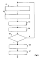
On présente ci-après, en relation avec la
La construction de l'arbre de décodage met en oeuvre au moins une itération des étapes suivantes, pour un noeud courant de l'arbre mémorisé dans une première pile.The construction of the decoding tree implements at least one iteration of the following steps, for a current node of the tree stored in a first stack.
L'algorithme débute au niveau du noeud racine. Le premier noeud courant est donc le noeud racine.The algorithm starts at the root node. The first current node is the root node.
Au cours d'une première étape 100, on détermine l'intervalle de sélection (à partir par exemple du rayon de la sphère) auquel les noeuds fils du noeud courant vont appartenir. On génère par la suite les noeuds fils appartenant à cet intervalle de sélection et on calcule les coûts associés à chacun de ces noeuds.During a
Les noeuds fils appartenant à cet intervalle de sélection sont mémorisés au cours d'une étape 101 dans la première pile. Ces noeuds fils représentent des branches autorisées pour le premier niveau de l'arbre.The child nodes belonging to this selection interval are stored during a
Le noeud courant est ensuite supprimé de la première pile au cours d'une étape 102, puis un nouveau noeud courant est sélectionné dans la première pile au cours d'une étape 103. Le nouveau noeud sélectionné est le noeud qui présente le coût le plus faible.The current node is then removed from the first stack during a
On teste (104) ensuite si le nouveau noeud courant est une feuille :
- O si le nouveau noeud courant est un noeud feuille, qui ne possède aucun noeud fils, on mémorise (105) le chemin entre le noeud racine et le noeud feuille, dans une deuxième pile, puis on supprime le noeud feuille de la première pile ;
- O sinon, on retourne à l'étape de sélection (100) d'au moins un noeud fils pour le nouveau noeud courant.
- O if the new current node is a leaf node, which has no child nodes, the path between the root node and the leaf node is stored (105) in a second stack and then the leaf node of the first stack is deleted;
- O otherwise, return to the step of selecting (100) at least one child node for the new current node.
Il est possible de mettre en oeuvre une seule ou plusieurs itérations de ces étapes 100 à 105.It is possible to implement one or more iterations of these
Chaque itération permet de mémoriser dans la deuxième pile un chemin entre le noeud racine et un nouveau noeud feuille.Each iteration makes it possible to memorize in the second stack a path between the root node and a new leaf node.
Il est alors possible, au cours d'une étape 106 de déterminer une estimation du signal de données, en tenant compte du ou des chemins mémorisés dans la deuxième pile. Ainsi, l'estimation du signal peut être une estimation binaire (décision dure) si la construction de l'arbre met en oeuvre une seule itération permettant de déterminer un unique chemin, ou bien être une estimation probabiliste (décision souple) si la construction de l'arbre met en oeuvre plusieurs itérations, permettant chacune de déterminer un chemin.It is then possible during a
En particulier, on peut noter que le procédé selon l'invention peut être mis en oeuvre de diverses manières, notamment sous forme câblée ou sous forme logicielle.In particular, it may be noted that the method according to the invention can be implemented in various ways, in particular in hard-wired form or in software form.
La technique de décodage proposée permet donc une construction progressive « horizontale » de l'arbre de décodage, dans le sens où l'on détermine pour un noeud courant l'ensemble des noeuds fils appartenant à l'intervalle de sélection.The proposed decoding technique therefore allows a "horizontal" progressive construction of the decoding tree, in the sense that all the child nodes belonging to the selection interval are determined for a current node.
De plus, on stocke dans la première pile chaque noeud associé à son coût. De cette façon, il n'est pas nécessaire de recalculer les données relatives à un noeud à chaque fois que l'on visite ce noeud.In addition, each node associated with its cost is stored in the first stack. In this way, it is not necessary to recalculate the data relating to a node each time this node is visited.
Ainsi, la technique de décodage selon l'invention repose sur une nouvelle approche du décodage à pile, permettant de diminuer la complexité du décodage, en diminuant la zone de recherche et le nombre de noeuds reconstruits, notamment lorsqu'une seule itération est mise en oeuvre. On combine ainsi les avantages d'un décodage à pile, en optimisant la construction de l'arbre de décodage, et d'un décodage par sphères, en limitant le nombre de noeuds considérés.Thus, the decoding technique according to the invention is based on a new approach to stack decoding, making it possible to reduce the complexity of the decoding, by reducing the search area and the number of reconstructed nodes, especially when a single iteration is implemented. artwork. The advantages of stack decoding are thus combined, by optimizing the construction of the decoding tree, and a decoding by spheres, by limiting the number of nodes considered.
De plus, l'invention proposée permet d'avoir une sortie probabiliste (ou souple), lorsque plusieurs itérations sont mises en oeuvre. En effet, la mise en oeuvre de plusieurs itérations permet de mémoriser dans une deuxième pile une liste de chemins candidats. Une telle sortie probabiliste peut s'avérer nécessaire par exemple si un codage de canal est utilisé en amont.In addition, the proposed invention makes it possible to have a probabilistic (or flexible) output, when several iterations are implemented. In fact, the implementation of several iterations makes it possible to memorize in a second stack a list of candidate paths. Such a probabilistic output may be necessary for example if a channel coding is used upstream.
L'invention peut notamment être intégrée dans un récepteur, par exemple pour le décodage de données transmises dans un canal MIMO (en anglais « Multiple Input Multiple Output » pour « entrée multiple sortie multiple ») ou pour une détection de multiples utilisateurs.The invention may in particular be integrated in a receiver, for example for the decoding of data transmitted in a MIMO channel (in English "Multiple Input Multiple Output" for multiple input multiple output) or for detection of multiple users.
En particulier, si les données transmises dans un canal MIMO sont codées par un code STBC (en anglais « Space Time Block Code » en français « codes spatio-temporels en blocs ») et émises sur un grand nombre d'antennes (au moins quatre antennes d'émission par exemple), la technique de décodage proposée permet de réduire la complexité du décodage. Par conséquent, la technique proposée permet de mettre en oeuvre des transmissions sans fil à haut débit présentant un faible taux d'erreur avec un récepteur de complexité raisonnable.In particular, if the data transmitted in a MIMO channel are encoded by an STBC code (in English "Space Time Block Code") and transmitted on a large number of antennas (at least four transmit antennas for example), the proposed decoding technique makes it possible to reduce the complexity of the decoding. Therefore, the proposed technique allows high bit rate wireless transmissions with a low error rate to be implemented with a receiver of reasonable complexity.
On décrit ci-après deux exemples d'application de l'invention, l'un relatif au décodage d'un signal reçu dans un système multi-antennes, l'autre au décodage d'un signal reçu dans un système multi-utilisateurs.Two examples of application of the invention are described below, one relating to the decoding of a signal received in a multi-antenna system and the other to the decoding of a signal received in a multi-user system.
En cas d'application à un décodage MIMO, les dimensions des signaux reçus correspondent à K (en notation réelle pour une modulation nQAM ou nPSK, en anglais « Phase Shift Keying », en français « modulation par déplacement de phase ») ou Q (en notation complexe pour une modulation nQAM ou nPSK ou en notation polaire pour une modulation nPSK). En cas d'application à une détection de plusieurs utilisateurs, les dimensions du signal reçu correspondent au nombre d'utilisateurs (Q en notation complexe ou notation polaire (si les utilisateurs utilisent une modulation nPSK)) ou K = 2Q en notation réelle.When applied to a MIMO decoding, the dimensions of the received signals correspond to K (in real notation for nQAM or nPSK modulation, in English "Phase Shift Keying") or Q ( in complex notation for nQAM or nPSK modulation or in polar notation for nPSK modulation). When applied to a multiple user detection, the received signal size corresponds to the number of users (Q in complex notation or polar notation (if users use nPSK modulation)) or K = 2Q in real notation.
On décrit ci-après un exemple de mise en oeuvre de l'invention dans le cadre d'une transmission MIMO mettant en oeuvre un code STBC en émission.An exemplary implementation of the invention in the context of a MIMO transmission implementing a transmitting STBC code is described below.
On rappelle en effet que les techniques de transmission multi-antennes permettent d'atteindre une capacité de transmission accrue en augmentant l'efficacité spectrale dans le canal de transmission, grâce à l'utilisation de codes espace/temps en émission. Ces codes espace/temps permettent notamment de répartir les symboles modulés sur les différents degrés de liberté du canal.It is recalled that the multi-antenna transmission techniques achieve an increased transmission capacity by increasing the spectral efficiency in the transmission channel, through the use of space codes / time transmission. These space / time codes make it possible to distribute the modulated symbols over the different degrees of freedom of the channel.
La
La
un codage convolutif 29,une modulation QAM 21, délivrant des symboles 22,- un codage espace/temps 23, délivrant un mot de
code 24 ; - une conversion temps/
fréquence 25 ; - une modulation OFDM (271 à 27Ntx) de chaque signal 261 à 26Ntx issu de la conversion temps/
fréquence 25 ; et - une émission sur Ntx antennes d'émission 281 à 28Ntx, chaque antenne d'émission étant associée à
un modulateur OFDM 271 à 27Ntx.
- a
convolutional coding 29, - a
QAM 21, deliveringsymbols 22, - a space / time coding 23, delivering a
codeword 24; - a time /
frequency conversion 25; - an OFDM modulation (27 1 to 27 Ntx ) of each signal 26 1 at 26 Ntx resulting from the time /
frequency conversion 25; and - a transmission on Ntx transmit
antennas 28 1 to 28 Ntx , each transmitting antenna being associated with anOFDM modulator 27 1 at 27 Ntx .
Plus précisément, l'émetteur 2 reçoit en entrée un signal binaire 20. Le signal binaire 20 est tout d'abord codé par un code convolutif 29, présentant par exemple un rendement égal à 1/2 avec comme polynômes générateurs (7,5) en notation octale. Ensuite, le signal est modulé par le modulateur 21 selon un premier schéma de modulation, par exemple une modulation d'amplitude en quadrature nQAM avec n égal à 16, 32, 64 ou 256, etc. Le modulateur 21 peut également mettre en oeuvre un schéma de modulation par déplacement de phase, par exemple de type nPSK, ou une modulation quelconque. L'étape de modulation 21 permet notamment de générer des symboles complexes appartenant au groupe de symboles S 1 à SQ. Par exemple, dans le cadre d'une modulation 4QAM, S 1 =1 + i, S2 = 1 - i, S3 = -1-i, et S4 = -1 + i.More precisely, the
Les symboles modulés 22 sont ensuite codés par le codeur espace-temps 23 pour former un mot de code STBC 24. Le code STBC est, par exemple, le Golden Code tel que décrit dans le document
Ainsi, le codage espace/temps peut être basé sur un code en bloc. Selon une variante, le codage espace/temps est un multiplexage spatial. Dans ce cas, les symboles modulés sont directement envoyés sur les antennes en émission.Thus, the space / time coding can be based on a block code. According to one variant, the space / time coding is a spatial multiplexing. In this case, the modulated symbols are sent directly to the transmitting antennas.
Le mot de code généré 24 est ensuite converti du domaine temporel vers le domaine fréquentiel et distribué sur les Ntx antennes d'émission. Chaque signal dédié 261 à 26Ntx est alors modulé par un modulateur OFDM 271 à 27Ntx, puis émis sur l'antenne d'émission 281 à 28Ntx correspondante, éventuellement après filtrage, transposition de fréquence et amplification (étapes classiquement mises en oeuvre pour un signal radiofréquence).The generated
L'architecture d'un émetteur selon cet exemple est plus précisément décrite dans le document
Bien entendu, la technique de décodage selon l'invention ne se limite pas à la réception d'un signal émis par un émetteur tel qu'illustré en
On présente désormais, en relation avec la
Selon l'exemple illustré, le récepteur 3 reçoit un signal y émis par l'émetteur 2 dans un canal sans fil. Un tel canal est généralement bruité. Il s'agit d'un canal à bruit blanc additif gaussien (ou AWGN de l'anglais « Additive White Gaussian Noise »), soumis à des évanouissements (en anglais « fading »). Le signal émis par l'émetteur 2 peut également être affecté par des échos dus aux trajets multiples et/ou à l'effet Doppler.According to the illustrated example, the
Selon l'exemple présenté, le récepteur 3 met en oeuvre :
- une réception sur Nrx antennes de réception 301 à 30Nrx, chaque antenne de réception étant associée à
un démodulateur OFDM 311 à 31Nrx ; une démodulation OFDM 311 à 31Nrx du signal reçu sur chaque antenne de réception, délivrant des signaux démodulés 321 à 32Nrx ;- une conversion fréquence /temps 33, mettant en oeuvre une opération inverse de la conversion temps /fréquence mise en oeuvre en émission,
délivrant un signal 34 dans le domaine fréquentiel ; - un décodage espace/temps 35, délivrant
un signal décodé 36 ; - une démodulation associée à
un décodage 37.
- reception on
Nrx receiving antennas 30 1 to 30 Nrx , each receiving antenna being associated with anOFDM demodulator 31 1 at 31 Nrx ; - an
OFDM demodulation 31 1 at 31 Nrx of the signal received on each receiving antenna, deliveringdemodulated signals 32 1 at 32 Nrx ; - a frequency /
time conversion 33, implementing an inverse operation of the time / frequency conversion implemented in transmission, delivering asignal 34 in the frequency domain; - a space / time decoding 35, delivering a decoded
signal 36; - demodulation associated with
decoding 37.
Selon l'exemple illustré, le récepteur 3 met en oeuvre un traitement inverse au traitement mis en oeuvre en émission. Ainsi, si une modulation monoporteuse est mise en oeuvre en émission au lieu d'une modulation multiporteuse, les démodulateurs OFDM 311 à 31Nrx sont remplacés par des démodulateurs monoporteuses correspondants.According to the illustrated example, the
Plus précisément, le récepteur 3 comprend Nrx antennes de réception 301 à 30Nrx. De cette façon, le signal reçu peut être représenté par une matrice de taille Nrx × N, ou de manière équivalente par un vecteur R de taille (Nrx × N) × 1, où N est, par exemple, égal à 2 et représente la plage temporelle et/ou fréquentielle occupée par le code espace/temps.More specifically, the
La transmission entre le codeur 23 et le décodeur 35 peut alors être modélisée par l'équation suivante : 
avec :
- R le vecteur complexe de taille (Nrx × N) × 1, reçu sur les Nrx antennes de réception ;
- Hi la matrice de canal complexe de taille Nrx × Ntx à l'intervalle temps/fréquence i, où la fréquence correspond à une porteuse de la modulation multiporteuse. Si la modulation mise en oeuvre est une modulation à porteuse simple, l'intervalle i correspond à un intervalle de temps ;
- H = diag(H 1,..., HN ) la matrice de canal complexe diagonale par bloc de taille (N × Nrx) × (N × Ntx) aux intervalles temps/
fréquence 1 à N ; - C la matrice de codage espace/temps complexe de taille (Ntx × N) × Q, où Q est le nombre de symboles complexes entrés par mot de code STBC ;
- S le vecteur d'entrée complexe des symboles modulés discrets, de taille Q x 1 ;
- v le vecteur complexe de bruit blanc additif gaussien de taille (N × Nrx) × 1, avec la matrice d'autocorrélation Rv = σ2 INNrx, où INNrx est la matrice unité de taille (N × Nrx) × (N × Nrx), et σ2 représente la variance du bruit AWGN.
with:
- R is the complex size vector ( Nrx × N ) × 1, received on the Nrx receiving antennas;
- H i the complex channel matrix of size Nrx × Ntx at the time / frequency interval i , where the frequency corresponds to a carrier of the multicarrier modulation. If the modulation implemented is a simple carrier modulation, the interval i corresponds to a time interval;
- H = diag ( H 1 , ..., H N ) the diagonal complex channel matrix per size block ( N × Nrx ) × ( N × Ntx ) at time /
frequency intervals 1 to N; - C is the complex space / time coding matrix of size ( Ntx × N ) × Q , where Q is the number of complex symbols entered per STBC code word;
- S is the complex input vector of discrete modulated symbols of
size Q x 1; - v the complex Gaussian additive white noise vector of size ( N × Nrx ) × 1, with the autocorrelation matrix R v = σ 2 INNrx, where INNrx is the matrix unit of size ( N × Nrx ) × ( N × Nrx) ), and σ 2 represents the AWGN noise variance.
Il est à noter que dans le cas où le codage spatio-temporel met en oeuvre des entrées réelles, au lieu d'entrées complexes, la matrice C de codage espace/temps est une matrice réelle ayant une dimension (2Ntx × N) × 2Q. It should be noted that in the case where the spatio-temporal coding implements real inputs, instead of complex inputs, the space / time coding matrix C is a real matrix having a dimension (2 Ntx × N ) × 2 Q.
De plus, lorsque le bruit additif et les interférences affectant le signal reçu ne sont pas blancs, un filtre de blanchiment peut être mis en oeuvre devant le décodeur espace/temps 35. La variable σ2 représente alors la variance du bruit blanchi résultant.In addition, when the additive noise and the interference affecting the received signal are not white, a bleaching filter can be implemented in front of the space /
L'algorithme de décodage à pile selon l'invention peut être mis en oeuvre lors de l'étape de décodage espace/temps 35. On considère alors que le décodeur espace/temps est un décodeur à pile, qui permet d'effectuer un décodage ML du signal codé.The battery decoding algorithm according to the invention can be implemented during the space /
Ce décodeur fournit un ou plusieurs signaux candidats, sous la forme de chemins mémorisés dans une deuxième pile.This decoder provides one or more candidate signals in the form of paths stored in a second stack.
Ces chemins peuvent notamment être utilisés pour affecter une probabilité de vraisemblance aux bits d'un symbole estimé.These paths can in particular be used to assign a probability of likelihood to the bits of an estimated symbol.
Le décodeur STBC 35 fournit alors le chemin obtenu, ou les probabilités de vraisemblance obtenues au démodulateur/décodeur 37.The
Le démodulateur/décodeur 37 est par exemple un décodeur Viterbi souple, mettant en oeuvre des opérations inverses aux étapes de modulation 21 et codage convolutif 29.The demodulator /
Ce démodulateur/décodeur 37 fournit une estimation dudit signal de données, en tenant compte du ou desdits chemins mémorisés dans ladite deuxième pile. Cette estimation peut être binaire ou probabiliste, selon le nombre d'itérations mises en oeuvre.This demodulator /
Par exemple, si la chaîne de transmission ne comporte pas de codage convolutif, une seule itération suffit pour décoder le message, et le premier chemin trouvé permet d'obtenir une estimation binaire du signal envoyé.For example, if the transmission chain does not include convolutional encoding, a single iteration is sufficient to decode the message, and the first path found provides a binary estimate of the sent signal.
La
- un microprocesseur 41 (ou CPU), qui est, par exemple, un processeur de signal numérique (ou DSP, en anglais « digital signal processor ») ;
- une mémoire non volatile 42 (ou ROM, en « anglais Read Only Memory ») ;
- une mémoire vive 43 (ou RAM, en anglais « Random Access Memory ») ;
une interface 45 pour la réception des signaux d'entrée provenant du convertisseur temps/fréquence 33 ;une interface 46 pour la transmission des données décodées au démodulateur/décodeur 37.
- a microprocessor 41 (or CPU), which is, for example, a digital signal processor (or DSP);
- a non-volatile memory 42 (or ROM, in English "Read Only Memory");
- RAM 43 (Random Access Memory);
- an
interface 45 for receiving the input signals from the time /frequency converter 33; - an
interface 46 for transmitting the decoded data to the demodulator /decoder 37.
Dans chacune des mémoires mentionnées, le mot « registre » utilisé dans la description peut correspondre à une zone de petite capacité (quelques bits) ou à une zone très étendue (par exemple tout un programme ou une grande quantité de données reçues ou décodées).In each of the memories mentioned, the word "register" used in the description may correspond to a zone of small capacity (a few bits) or to a very large area (for example a whole program or a large quantity of data received or decoded).
La mémoire non volatile ROM 42 comprend :
un programme Prog 420 ;un biais b 421.
- a Prog 420 program;
- a
bias b 421.
Les algorithmes pour la mise en oeuvre du procédé selon ce mode de réalisation de l'invention peuvent être stockés dans le registre 420. Lorsqu'il est mis sous tension, le processeur CPU 41 télécharge le programme 420 dans la mémoire RAM et exécute les instructions correspondantes.The algorithms for implementing the method according to this embodiment of the invention can be stored in the
La mémoire vive RAM 43 comprend :
- dans
un registre Prog 430, le programme exécuté par le microprocesseur 41 et téléchargé après la mise sous tension du décodeur espace/temps 35 ; - des données d'entrée dans un registre 431 ;
- des données relatives aux noeuds dans un registre 432, correspondant à une première pile ;
- des données relatives aux chemins déterminés à chaque itération, désignés par ai, dans un registre 433 correspondant à une deuxième pile ;
- des probabilités de vraisemblance ou LLR dans
un registre 434 ; - le nombre maximal de chemins pouvant être mémorisés dans la deuxième pile, désigné par M dans
un registre 435 ; et - un compteur p utilisé pour compter le nombre de chemins mémorisés dans la deuxième pile, défini dans
un registre 436.
- in a
Prog register 430, the program executed by themicroprocessor 41 and downloaded after power-up of the space /time decoder 35; - input data in a
register 431; - data relating to the nodes in a
register 432, corresponding to a first stack; - data relating to the paths determined at each iteration, designated a i , in a
register 433 corresponding to a second stack; - likelihood probabilities or LLR in a
register 434; - the maximum number of paths that can be stored in the second stack, designated M in a
register 435; and - a counter p used to count the number of paths stored in the second stack, defined in a
register 436.
Plus précisément, les données stockées dans le registre 432 comprennent, pour un noeud de l'arbre de décodage, le coût associé à ce noeud, le chemin de la racine à ce noeud, et éventuellement la dimension de ce noeud, c'est-à-dire sa profondeur dans l'arbre. On rappelle que le coût associé à un noeud courant est défini par la distance euclidienne entre le signal reçu, et le chemin entre le noeud racine et le noeud courant.More specifically, the data stored in the
Selon un autre mode de réalisation, la technique de décodage selon l'invention peut être mise en oeuvre selon une configuration uniquement matérielle (par exemple dans un ou plusieurs circuits intégrés de type FPGA, ASIC ou VLSI avec la mémoire correspondante) ou selon une configuration utilisant à la fois des VLSI et DSP.According to another embodiment, the decoding technique according to the invention can be implemented according to a purely hardware configuration (for example in one or more integrated circuits of the FPGA, ASIC or VLSI type with the corresponding memory) or according to a configuration using both VLSI and DSP.
La
Ainsi, selon cet exemple de mise en oeuvre, le décodeur délivre une décision souple (en anglais « soft »), c'est-à-dire une estimation probabiliste d'un symbole transmis.Thus, according to this exemplary implementation, the decoder delivers a soft decision (in English "soft"), that is to say a probabilistic estimation of a transmitted symbol.
Pour ce faire, le décodeur espace/temps 35 met en oeuvre au moins deux itérations de décodage à pile :
- une première itération permettant de mémoriser un premier chemin entre le noeud racine de l'arbre et un noeud feuille, correspondant à un premier signal candidat ;
- au moins une deuxième itération permettant de mémoriser au moins un deuxième chemin entre le noeud racine de l'arbre et un autre noeud feuille, correspondant à au moins un deuxième signal candidat.
- a first iteration for storing a first path between the root node of the tree and a leaf node corresponding to a first candidate signal;
- at least a second iteration for storing at least a second path between the root node of the tree and another leaf node corresponding to at least a second candidate signal.
Plus précisément, au cours d'une étape d'initialisation 50, les différents paramètres du procédé sont initialisés. Par exemple, le compteur p est mis à zéro.More specifically, during an
Durant une étape suivante 51, le décodeur attend de recevoir un signal, issu par exemple du convertisseur temps/fréquence 33.During a
Une fois le signal reçu, le décodeur met en oeuvre une première itération de décodage à pile 52. Au cours de cette première itération, le meilleur chemin entre le noeud racine de l'arbre et une feuille est mémorisé dans la deuxième pile. Le compteur d'itérations p est mis à la valeur 1 (p = 1). Cette première itération peut mettre en oeuvre en algorithme de décodage à pile classique. Avantageusement, elle met en oeuvre une réduction du nombre de noeuds fils générés en ne sélectionnant que les noeuds fils appartenant à un intervalle prédéterminé.Once the signal has been received, the decoder implements a first
Si le nombre maximal d'itérations M est égal à 1, une seule itération est effectuée, et une sortie binaire de l'algorithme est donnée.If the maximum number of iterations M is equal to 1, a single iteration is performed, and a binary output of the algorithm is given.
Ensuite, le décodeur met en oeuvre une deuxième itération de décodage à pile 53. Au cours de cette deuxième itération, le meilleur chemin entre le noeud racine de l'arbre et une nouvelle feuille est mémorisé dans la deuxième pile. Le compteur d'itérations p est incrémenté d'une unité (p = p + 1). Cette nouvelle itération 53 est donc basée sur un arbre réduit excluant les chemins précédemment mémorisés dans la deuxième pile. En d'autres termes, la deuxième itération applique une technique de décodage à pile à l'arbre utilisé par la première itération de décodage à pile, en excluant le chemin obtenu lors de la première itération.Then, the decoder implements a second
On teste alors au cours d'une étape de test 54 si le compteur d'itérations p, a atteint le nombre maximal d'itérations M.It is then tested during a
Le nombre d'itération maximum est égal au nombre de noeuds feuilles dans l'arbre de décodage.The maximum number of iterations is equal to the number of leaf nodes in the decoding tree.
Afin de limiter le temps de décodage, il est possible de limiter le nombre d'itérations en limitant la taille de la deuxième pile : chaque chemin obtenu lors d'une itération étant mémorisé dans la deuxième pile, le nombre d'itérations peut être limité par la taille de la deuxième pile.In order to limit the decoding time, it is possible to limit the number of iterations by limiting the size of the second stack: each path obtained during an iteration being stored in the second stack, the number of iterations can be limited. by the size of the second stack.
Selon une autre variante permettant également de limiter le temps de décodage, on peut fixer un coût maximal que le ou les noeuds feuilles ne doivent pas dépasser, et ne générer que les chemins présentant un coût inférieur ou égal à ce seuil prédéterminé. En d'autres termes, on mémorise un premier chemin dans la deuxième pile lors de la première itération, puis un deuxième chemin lors de l'itération suivante, puis un troisième chemin lors de l'itération suivante, et ainsi de suite, tant que le coût associé au dernier chemin mémorisé reste inférieur ou égal à ce seuil prédéterminé.According to another variant which also makes it possible to limit the decoding time, it is possible to fix a maximum cost that the at least one leaf node must not exceed, and to generate only the paths presenting a cost that is lower than or equal to this predetermined threshold. In other words, we memorize a first path in the second stack during the first iteration, then a second path during the next iteration, then a third path during the next iteration, and so on, as long as the cost associated with the last stored path remains less than or equal to this predetermined threshold.
Ainsi, si le compteur d'itérations p n'a pas atteint le nombre maximal d'itérations M, le décodeur met en oeuvre une nouvelle itération de décodage à pile 53, et incrémente le compteur d'itérations d'une unité. La jème itération de décodage à pile est appliquée au signal reçu en excluant la ou les chemins déterminé(s) durant la ou les (j-1) itérations précédentes du décodage à pile.Thus, if the iteration counter p has not reached the maximum number of iterations M , the decoder implements a new
Si le compteur d'itérations p n'a pas atteint le nombre maximal d'itérations M, ce qui signifie que tous les chemins ont été déterminés et mémorisés dans la deuxième pile, on affecte une probabilité de vraisemblance à chaque bit du symbole estimé, au cours d'une étape 55.If the iteration counter p has not reached the maximum number of iterations M , which means that all the paths have been determined and stored in the second stack, a probability of likelihood is assigned to each bit of the estimated symbol, during a
Par exemple, si le chemin obtenu lors d'une première itération est le chemin défini par les bits [1011], et le chemin obtenu lors d'une deuxième itération est le chemin défini par les bits [1111], on peut affecter une forte probabilité de vraisemblance aux premier, troisième et quatrième bits. En revanche, on affectera une probabilité de vraisemblance plus faible au deuxième bit, qui est égal à 0 selon le chemin défini par la première itération, et égal à 1 selon le chemin défini par la deuxième itération.For example, if the path obtained during a first iteration is the path defined by the bits [1011], and the path obtained during a second iteration is the path defined by the bits [1111], we can assign a strong probability of likelihood at the first, third and fourth bits. On the other hand, we will assign a lower likelihood probability to the second bit, which is equal to 0 according to the path defined by the first iteration, and equal to 1 according to the path defined by the second iteration.
Ces probabilités a posteriori peuvent notamment s'exprimer sous la forme de logarithme du rapport de vraisemblance (ou LLR, en anglais « Log Likelihood Ratio »). Ainsi, une fois que tous les chemins sont déterminés (c'est-à-dire que toutes les itérations sont mises en oeuvre), un LLR est calculé pour chaque symbole de la modulation.These posterior probabilities can in particular be expressed in the form of logarithm of the likelihood ratio (or LLR, in English "Log Likelihood Ratio"). Thus, once all paths are determined (i.e. all iterations are implemented), an LLR is calculated for each symbol of the modulation.
En notant y le signal reçu et H la matrice de canal, le LLR du ième bit bi peut s'exprimer sous la forme suivante, comme décrit dans les documents 
Ces étapes de test 54 et de détermination des probabilités de vraisemblance 55 sont par exemple effectuées par un DSP et/ou par un VLSI (par exemple de type ASIC ou FPGA).These test steps 54 and the determination of the
Finalement, durant une étape 56, les probabilités de vraisemblance affectées aux différents bits sont transmises au démodulateur/décodeur 37. De cette façon, il est possible de déterminer une estimation du signal de données, tenant compte des différents chemins mémorisés dans la deuxième pile.Finally, during a
Après l'étape 56 de transmission du résultat, l'étape d'initialisation 51 peut être réitérée.After the
On décrit ci-après de manière détaillée, en relation avec la
Pour ce faire, on considère de nouveau que le signal reçu peut s'exprimer sous la forme suivante : 
On suppose également que le décodeur connaît la matrice de canal H = diag(H1 ,..., HN ). Pour ce faire, une technique classique d'estimation de canal, basé sur la connaissance de symboles pilotes peut être mise en oeuvre.It is also assumed that the decoder knows the channel matrix H = diag ( H 1 , ..., H N ). To do this, a conventional channel estimation technique, based on the knowledge of pilot symbols can be implemented.
Chaque mot de code espace/temps est donc obtenu par une multiplication matricielle CS.Each space / time code word is thus obtained by a matrix multiplication CS.
On peut noter que le codage du signal entrant S peut être représenté par des multiplications de matrices complexes ou par des matrices réelles dans lesquelles les parties réelle et imaginaire sont codées séparément. Par exemple, le schéma de codage décrit dans le document « Space-Time block coding : A simple transmitter diversity technique for wireless communications » précédemment cité ne peut être représenté qu'avec des notations réelles.It may be noted that the coding of the incoming signal S can be represented by multiplications of complex matrices or by real matrices in which the real and imaginary parts are coded separately. For example, the coding scheme described in the document " Space-Time block coding: A simple transmitter diversity technique for wireless communications " previously cited can only be represented with real notations.
Ainsi, une écriture plus générale de l'équation (1) donne : 
où:
- C' est la matrice de codage espace/temps avec des notations réelles,
- (.) R et (.) I désignent respectivement les parties réelle et imaginaire d'un nombre ou d'une matrice complexe.
or:
- It is the space / time coding matrix with real notations,
- (.) R and (.) I respectively denote the real and imaginary parts of a complex number or matrix.
Avec des notations réelles, la dimension du signal entrant S' est K = 2Q. Lorsque S est modulé en utilisant une modulation d'amplitude en quadrature, chacune des composantes de S' est soumise à une modulation d'impulsions en amplitude (PAM). La matrice G' correspond alors à une base du réseau de dimension K = 2Q.With real notations, the size of the incoming signal S 'is K = 2Q. When S is modulated using quadrature amplitude modulation, each of S 'components is subjected to amplitude pulse modulation (PAM). The matrix G 'then corresponds to a base of the network of dimension K = 2Q.
Il est à noter que les algorithmes de décodage séquentiels utilisent de manière avantageuse une matrice triangulaire en tant que base. Par conséquent, il est préférable de réaliser une décomposition de la matrice d'évanouissement G', encore appelée matrice de canal équivalent (tenant compte de la matrice de canal et de la matrice de codage espace/temps).It should be noted that the sequential decoding algorithms advantageously use a triangular matrix as a base. Therefore, it is preferable to perform a decomposition of the fading matrix G ', also called equivalent channel matrix (taking into account the channel matrix and the space / time coding matrix).
De cette façon, il est préférable de construire l'arbre de décodage à partir d'une décomposition QR de la matrice G'.In this way, it is preferable to build the decoding tree from a QR decomposition of the matrix G '.
On obtient ainsi (où l'opérateur t désigne la transposée) : ![]()
![]()
- G' = QU est la décomposition QR de la matrice G' ;
- U est une matrice triangulaire supérieure de taille K × K ;
- Q est une matrice orthogonale telle que Q × Qt = Ik ;
- Rp est le nouveau vecteur d'observation de taille K × 1 ; et
- η est le vecteur de bruit de taille K × 1 avec l'autocorrélation

- G '= QU is the QR decomposition of the matrix G';
- U is an upper triangular matrix of size K × K ;
- Q is an orthogonal matrix such that Q × Q t = I k ;
- Rp is the new observation vector of size K × 1; and
- η is the noise vector of size K × 1 with autocorrelation
La matrice triangulaire U correspond alors à la nouvelle base utilisée par l'algorithme de décodage séquentiel.The triangular matrix U then corresponds to the new base used by the sequential decoding algorithm.
Selon une variante, la dimension temps/fréquence N est remplacée par une dimension temps si une modulation à porteuse unique est utilisée.According to one variant, the time / frequency dimension N is replaced by a time dimension if a single carrier modulation is used.
A partir du nouveau signal observé Rp et de la connaissance du canal, le décodeur peut construire un arbre de décodage et trouver une bonne estimation du signal transmis S.From the new observed signal R p and the knowledge of the channel, the decoder can build a decoding tree and find a good estimate of the transmitted signal S.
Il est également possible d'utiliser une décomposition de Cholesky de la matrice de Gram pour décomposer la matrice G' et obtenir une matrice triangulaire en tant que base.It is also possible to use a Cholesky decomposition of the Gram matrix to decompose the matrix G 'and obtain a triangular matrix as a base.
Pour ce faire, le CPU exécute une décomposition triangulaire. Cette opération fournit une matrice triangulaire U correspondant à la matrice de Gram. Plus précisément, grâce à la structure de G', une matrice triangulaire U est définie comme suit : ![]()
![]()
Ensuite, le signal reçu est projeté dans la matrice triangulaire U déterminée à l'étape précédente. Cette projection multiplie d'abord le signal reçu R' par G't et ensuite par l'inverse de Ut .Then, the received signal is projected in the triangular matrix U determined in the previous step. This projection first multiplies the received signal R 'by G' t and then by the inverse of U t .
Comme illustré en relation avec la
Lors de la première étape de sélection 61, le noeud courant correspond au noeud racine.In the
Chaque noeud est associé à un coût (ou métrique), à un chemin, et éventuellement à une dimension (ou profondeur). La dimension correspond au nombre de niveaux entre le noeud en question et la racine, profondeur de l'arbre. La métrique d'un noeud correspond à la distance euclidienne (ou, selon une variante, à une fonction de la distance telle que, par exemple, le carré de la distance) entre les signaux reçus et le chemin entre le noeud racine et le noeud considéré. Dans l'arbre, il y a un seul chemin entre le noeud racine et le noeud considéré. Ce chemin permet de déterminer les bits décodés correspondants (ou une estimation de la séquence d'information transmise) entre le noeud racine et le noeud considéré.Each node is associated with a cost (or metric), a path, and possibly a dimension (or depth). The dimension is the number of levels between the node in question and the root, depth of the tree. The metric of a node corresponds to the Euclidean distance (or, alternatively, to a distance function such as, for example, the square of the distance) between the received signals and the path between the root node and the node considered. In the tree, there is only one path between the root node and the considered node. This path makes it possible to determine the corresponding decoded bits (or an estimate of the transmitted information sequence) between the root node and the considered node.
Durant une étape suivante 62, les coûts des noeuds fils appartenant à un intervalle prédéterminé sont calculés. Le coût associé à un noeud fils est égal à la somme du coût de son noeud parent et de la contribution du chemin entre son noeud parent et lui-même (distance euclidienne entre le signal reçu et le chemin relatif à la transition entre le noeud parent et le noeud fils considéré). Ce mode de réalisation permet un décodage au sens ML.During a
Selon une variante de l'invention, un biais (ou un multiple d'un biais fixe désigné par b) est soustrait au coût associé au noeud fils. Le coût associé à un noeud fils avec une dimension dim comporte un biais total égal à la dimension dim multipliée par b. Cette variante permet une réduction de la complexité, mais fournit de moins bonnes performances que le décodage au sens ML. La complexité de décodage est donc diminuée, mais le décodage est sous-optimal. Le biais est choisi en fonction d'un taux d'erreur binaire (BER, ou « Binary Error Rate ») désiré, afin d'obtenir un bon rapport signal à bruit (SNR) tout en conservant une complexité raisonnable. Plus précisément, lorsqu'un biais est introduit, les chemins les plus avancés dans l'arbre sont privilégiés et un noeud feuille est atteint plus rapidement. De cette façon, le décodeur peut fournir une solution d'autant plus rapide que le biais est élevé.According to a variant of the invention, a bias (or a multiple of a fixed bias designated by b ) is subtracted from the cost associated with the child node. The cost associated with a child node with a dimension dim has a total bias equal to the dimension dim multiplied by b . This variant makes it possible to reduce the complexity, but provides poorer performance than ML decoding. The decoding complexity is therefore reduced, but the decoding is suboptimal. The bias is chosen according to a desired binary error rate (BER), in order to obtain a good signal-to-noise ratio (SNR) while maintaining a reasonable complexity. Specifically, when a bias is introduced, the most advanced paths in the tree are privileged and a leaf node is reached faster. In this way, the decoder can provide a solution all the faster as the bias is high.
Une fois les coûts associés aux noeuds fils calculés, on mémorise dans une première pile les données relatives aux noeuds fils (coût, chemin, éventuellement dimension). On supprime ensuite le noeud courant dans la première pile au cours d'une étape 63.Once the costs associated with the calculated child nodes, the data relating to the child nodes (cost, path, possibly dimension) are stored in a first stack. The current node is then removed in the first stack during a
Au cours d'une étape suivante 64, on sélectionne dans la première pile un nouveau noeud courant en tenant compte du coût associé. Selon le mode de réalisation décrit, on choisit le noeud qui a le coût le plus faible.During a
Si la première pile est ordonnancée en fonction des coûts, de façon que le noeud présentant le coût le plus faible soit situé au sommet de la pile, le noeud sélectionné au cours de l'étape 64 est le premier noeud de la pile.If the first stack is cost-sequenced, so that the lowest cost node is at the top of the stack, the node selected in
Au cours d'une étape de test 65, le décodeur vérifie si le nouveau noeud courant est un noeud feuille. Si ce n'est pas le cas, on retourne à l'étape 61 de sélection d'au moins un noeud fils pour le nouveau noeud courant.During a
Si le nouveau noeud courant est un noeud feuille, on mémorise dans une deuxième pile, au cours d'une étape 66, le chemin entre le noeud racine de l'arbre, et le noeud feuille. En d'autres termes, un signal candidat est sélectionné et stocké en mémoire. On supprime ensuite ce noeud feuille de la première pile.If the new current node is a leaf node, it memorizes in a second stack, during a
Le compteur d'itérations p est alors mis à jour au cours d'une étape 67. On rappelle que p est égal à 1 pour la première itération (52), puis incrémenté d'une unité lors des itérations suivantes (53).The iteration counter p is then updated during a
Les noeuds fils considérés appartiennent à un intervalle prédéterminé, ce qui revient à dire qu'un noeud fils n'est pris en considération que lorsque sa métrique est égale ou inférieure à un seuil désigné par C. De cette façon, on ne stocke dans la première pile que les données relatives aux noeuds fils présentant un coût inférieur au seuil C.The considered child nodes belong to a predetermined interval, which is to say that a child node is taken into consideration only when its metric is equal to or less than a threshold designated by C. In this way, one stores in the first stack only the data relating to the son nodes having a cost lower than the threshold C.
Ce seuil correspond par exemple au rayon d'une sphère centrée sur le signal reçu, et les chemins parcourus dans l'arbre correspondent aux points du réseau se trouvant à l'intérieur de cette sphère.This threshold corresponds for example to the radius of a sphere centered on the received signal, and the paths traveled in the tree correspond to the points of the network lying inside this sphere.
Par exemple, en utilisant les mêmes formules que celles proposées dans le document « A Universal Lattice Code Decoder for Fading and Channels », on obtient pour chaque composante réelle ou imaginaire d'un symbole du signal à décoder un intervalle Ii = [binf i , Bsup i ]. Pour ajouter la contrainte liée à la constellation, on fait l'intersection entre l'intervalle [C min, C max] correspondant à la constellation (moyennant un changement de variable pour se placer dans Z) et les intervalles Ii . L'intervalle final auquel les noeuds du i ème niveau peuvent appartenir est : Iifinal = [max(C min, B inf i ), min(C max, B sup i )].For example, by using the same formulas as those proposed in the document " Universal Lattice Code Decoder for Fading and Channels ", for each real or imaginary component of a symbol of the signal to be decoded an interval I i = [ b inf i , B sup i ]. To add the constraint related to the constellation, we make the intersection between the interval [ C min, C max] corresponding to the constellation (with a change of variable to be placed in Z) and the intervals I i . The final interval to which the nodes of the i th level can belong is: I ifinal = [max ( C min, B inf i ), min ( C max, B sup i )].
Cette valeur de seuil C peut être fixée arbitrairement.This threshold value C can be set arbitrarily.
Par exemple, le rayon peut être calculé en fonction du rapport signal à bruit SNR en utilisant la formule suivante, proposée par Hassibi et al. dans « On the expected complexity of sphere decoding » : ![]()
![]()
Un choix plus judicieux du rayon, peut être fait en tenant compte des évanouissements du canal, et par la suite de la matrice G', comme cela est proposé pour les décodeurs par sphère. Ainsi, le rayon peut être calculé en utilisant la formule suivante, proposée par G. Rekaya dans « Nouvelles constructions algébriques de code spatio-temporels atteignant le compromis multiplexage-diversité » : ![]()
![]()
La valeur du seuil C peut également être définie dynamiquement, en fonction d'une ou plusieurs caractéristiques du canal de transmission.The value of the threshold C can also be defined dynamically, depending on one or more characteristics of the transmission channel.
De cette façon, on ne mémorise dans la première pile lors de l'étape 63 que les noeuds fils d'un noeud courant présentant un coût inférieur ou égal au seuil C, déterminé dynamiquement ou fixé arbitrairement. On considère par exemple que pour un noeud courant, les k noeuds fils ayant les métriques les plus basses sont conservés et les autres sont rejetés.In this way, only the child nodes of a current node having a cost less than or equal to the threshold C, determined dynamically or fixed arbitrarily, are stored in the first stack during
Par exemple, si le nombre maximal de fils pour un noeud est égal à 2, on peut choisir C de façon à avoir k égal à 1. On diminue ainsi de manière conséquente le nombre de chemins possibles dans l'arbre.For example, if the maximum number of threads for a node is 2, one can choose C so that k is equal to 1. This reduces the number of possible paths in the tree accordingly.
La valeur de k peut notamment dépendre de la profondeur à l'intérieur de l'arbre. Ainsi, plus de noeuds fils peuvent être générés pour de petites dimensions et moins de noeuds fils pour des dimensions plus élevées. Par exemple, si l'on cherche à décoder quatre symboles complexes de modulation 4-QAM, un arbre de profondeur égale à 8, dans lequel chaque noeud a deux fils, peut être utilisé. Pour les quatre premières dimensions, on peut déterminer à chaque fois les deux noeuds fils possibles, puis pour les quatre dernières dimensions, on peut ne générer qu'un seul des deux noeuds fils.The value of k can depend in particular on the depth inside the tree. Thus, more child nodes can be generated for smaller dimensions and fewer child nodes for higher dimensions. For example, if one seeks to decode four complex symbols of 4-QAM modulation, a tree of depth equal to 8, in which each node has two son, can be used. For the first four dimensions, we can determine each time the two possible son nodes, then for the last four dimensions, we can generate only one of the two son nodes.
On présente désormais, en relation avec la
On considère que le seuil C est très grand, de façon à couvrir le plus de chemins possibles.We consider that threshold C is very large, so as to cover as many paths as possible.
Tout d'abord, à partir du noeud racine 8, deux noeuds fils 80 et 81 sont générés durant les étapes de génération d'au moins un noeud fils 61 et de calcul des coûts associés 62. Le chemin et la métrique correspondants sont respectivement :
- 0 et C1 pour le noeud fils 80 ;et
- 1 et C2 pour le noeud fils 81.
- 0 and C1 for the
child node 80, and - 1 and C2 for the
child node 81.
La première pile contient alors les données associées aux noeuds 80 et 81.The first stack then contains the data associated with the
Ensuite, en supposant que la métrique C2 est inférieure à la métrique C1 (C2 < C1), le nouveau noeud courant sélectionné au cours de l'étape 64 est le noeud 81.Then, assuming that metric C2 is smaller than metric C1 (C2 <C1), the new current node selected in
A partir du nouveau noeud courant 81, deux noeuds fils 810 et 811 sont générés durant les étapes de génération d'au moins un noeud fils 61 et de calcul des coûts associés 62. Le chemin et la métrique correspondants sont respectivement :
- 10 et C21 pour le noeud 810 ; et
- 11 et C22 pour le noeud 811.
- And C21 for
node 810; and - 11 and C22 for the
node 811.
En supposant que la métrique C21 est inférieure à la métrique C22, le nouveau noeud courant sélectionné au cours de l'étape 64 est le noeud 810. De plus, si la première pile est ordonnée en positionnant au sommet de la pile le noeud présentant le coût le plus faible, et en supposant que la métrique C22 est inférieure à la métrique C1 (C21 < C22 < C1), alors la première pile contient le noeud 810 (sommet de la pile), puis le noeud 811 et finalement le noeud 80 (base de la pile). Le contenu de la première pile à cet instant est illustré en
A partir du nouveau noeud courant 810, deux noeuds fils 8100 et 8101 sont générés. Le chemin et la métrique correspondants sont respectivement :
- 100 et C211 pour le noeud 8100 ; et
- 101 et C212 pour le noeud 8101.
- 100 and C211 for
node 8100; and - 101 and C212 for the
node 8101.
En supposant que la métrique C211 est inférieure à la métrique C212, le nouveau noeud courant sélectionné au cours de l'étape 64 est le noeud 8100. Si la métrique C212 est inférieure à la métrique C22 (C211 < C212 < C22 < C1), alors la première pile contient le noeud 8100 (sommet de la pile), puis le noeud 8101, puis le noeud 811 et finalement le noeud 80 (base de la pile). Le contenu de la première pile à cet instant est illustré en
A partir du nouveau noeud courant 8100, deux noeuds fils 81000 et 81001 sont générés. Le chemin et la métrique correspondants sont respectivement :
- 1000 et C2111 pour
le noeud 81000 ; et - 1001 et C2112 pour
le noeud 81001.
- 1000 and C2111 for the
node 81000; and - 1001 and C2112 for the
node 81001.
En supposant que la métrique C212 est inférieure aux métriques C2111 et C2112, le nouveau noeud courant sélectionné au cours de l'étape 64 est le noeud 8101.Assuming that metric C212 is smaller than metrics C2111 and C2112, the new current node selected in
Si la métrique C22 est inférieure à la métrique C2112, qui est inférieure à la métrique C2111, elle-même inférieure à C1 (C212 < C22 < C2112 < C2111 < C1), alors la première pile contient le noeud 8101 (sommet de la pile), puis le noeud 811, puis le noeud 81001, puis le noeud 81000, et finalement le noeud 80 (base de la pile). Le contenu de la première pile à cet instant est illustré en
A partir du nouveau noeud courant 8101, deux noeuds fils 81010 et 81011 sont générés. Le chemin et la métrique correspondants sont respectivement :
- 1010 et C2121 pour le noeud 81001 ; et
- 1011 et C2122 pour
le noeud 81011.
- 1010 and C2121 for
node 81001; and - 1011 and C2122 for the
node 81011.
En supposant C2121 < C22 < C2122 < C2112 < C2111 < C1, le nouveau noeud courant sélectionné au cours de l'étape 64 est le noeud 81010.Assuming C2121 <C22 <C2122 <C2112 <C2111 <C1, the new current node selected in
La première pile contient alors le noeud 81010 (sommet de la pile), puis le noeud 811, puis le noeud 81011, puis le noeud 81001, puis le noeud 81000 et finalement le noeud 80 (base de la pile). Le contenu de la première pile à cet instant est illustré en
Si le nouveau noeud sélectionné 81010 est identifié comme étant un noeud feuille au cours de l'étape de test 65, alors le chemin entre la racine de l'arbre et le noeud 81010 est mémorisé dans une deuxième pile. Il s'agit d'un premier signal candidat, notée a1 Ainsi, la deuxième pile contient le chemin C2121, correspondant aux bits [1010].If the selected
La première itération de décodage à pile 52 est terminée.The first
Si le nombre maximal d'itérations M est égal à 1, une seule itération est effectuée, et une estimation binaire de la séquence émise est calculée.If the maximum number of iterations M is equal to 1, a single iteration is performed, and a binary estimate of the transmitted sequence is computed.
Si le nombre maximal d'itérations M est supérieur à 1, on passe à une deuxième itération.If the maximum number of iterations M is greater than 1, we proceed to a second iteration.
La deuxième itération de décodage à pile 53 est mise en oeuvre. Cette deuxième itération est appliquée à l'arbre en excluant la première solution candidate a1, c'est-à-dire en supprimant le noeud feuille 81010 de façon à déterminer un nouveau chemin entre la racine de l'arbre et une feuille.The second
Pour ce faire, après suppression du noeud courant 81010 dans la première pile, on sélectionne un nouveau noeud courant, présentant le coût associé le plus faible. Il s'agit du noeud 811.To do this, after deleting the
A partir du nouveau noeud courant 811, deux noeuds fils 8110 et 8111 sont générés. Le chemin et la métrique correspondants sont respectivement :
- 110 et C221 pour le noeud 8110 ; et
- 111 et C222 pour le noeud 8111.
- 110 and C221 for the
node 8110; and - 111 and C222 for the
node 8111.
En supposant que la métrique C222 est inférieure à la métrique C221 (C222 < C2122 < C2112 < C2111 < C221 < C1), le nouveau noeud courant sélectionné au cours de l'étape 64 est le noeud 8111. La première pile contient alors le noeud 8111 (sommet de la pile), puis le noeud 81011, puis le noeud 81001, puis le noeud 81000, puis le noeud 8110, et finalement le noeud 80 (base de la pile). Le contenu de la première pile à cet instant est illustré en
A partir du nouveau noeud courant 8111, deux noeuds fils 81110 et 81111 sont générés. Le chemin et la métrique correspondants sont respectivement :
- 1110 et C2221 pour le noeud 81110 ; et
- 1111 et C2222 pour
le noeud 81111.
- 1110 and C2221 for the
node 81110; and - 1111 and C2222 for the
node 81111.
En supposant que la métrique C2221 est inférieure à la métrique C2222 (C2221 < C2222 < C2122 < C2112 < C2111 < C221 < C1), le nouveau noeud courant sélectionné au cours de l'étape 64 est le noeud 81110.Assuming that the metric C2221 is smaller than the C2222 metric (C2221 <C2222 <C2122 <C2112 <C2111 <C221 <C1), the new current node selected in
La première pile contient alors le noeud 81110 (sommet de la pile), puis le noeud 81111, puis le noeud 81011, puis le noeud 81001, puis le noeud 81000, puis le noeud 8110, et finalement le noeud 80 (base de la pile). Le contenu de la première pile à cet instant est illustré en
Si le nouveau noeud sélectionné 81110 est identifié comme étant un noeud feuille au cours de l'étape de test 65, alors le chemin entre la racine de l'arbre et le noeud 81110 est mémorisé dans la deuxième pile. Il s'agit d'un deuxième signal candidat, notée a2 Ainsi, la deuxième pile contient, en plus du chemin C2121, correspondant aux bits [1010], déterminé au cours de la première itération, le chemin C2221, correspondant aux bits [1110].If the new selected
La deuxième itération de décodage à pile 53 est terminée.The second
Il est possible de prévoir de nouvelles itérations, en supprimant le noeud courant 81110 de la première pile.It is possible to provide new iterations, removing the
Comme déjà discuté, les
La deuxième pile, qui comprend une liste de chemins candidats, est quant à elle ordonnée par construction. Lors de l'étape de détermination d'une estimation probabiliste du signal de données, on peut choisir d'accorder une plus grande confiance aux chemins situés au sommet de la deuxième pile. Ainsi, on peut n'utiliser que les chemins les plus fiables de la deuxième pile pour calculer les probabilités de vraisemblance.The second stack, which includes a list of candidate paths, is ordered by construction. During the step of determining a probabilistic estimation of the data signal, it is possible to choose to grant greater confidence to the paths located at the top of the second stack. Thus, only the most reliable paths of the second stack can be used to calculate the likelihood probabilities.
On décrit ci-après un exemple de mise en oeuvre de l'invention dans le cadre d'une détection de multi-utilisateurs.An exemplary implementation of the invention in the context of a multi-user detection is described below.
On considère dans ce contexte un système de transmission comprenant un récepteur et une pluralité d'émetteurs, comprenant chacun une seule antenne, chaque émetteur pouvant être identifié par un schéma d'accès multiple (par exemple de type CDMA (en anglais « Code Division Multiple Access », en français « accès multiple par répartition en code »), « flash OFDM », ...). Plusieurs utilisateurs partagent donc la même ressource de transmission pour transmettre des données au récepteur.In this context, a transmission system is considered comprising a receiver and a plurality of transmitters, each comprising a single antenna, each transmitter being able to be identified by a multiple access scheme (for example of the CDMA type). Access ", in French" code division multiple access ")," OFDM flash ", ...). Multiple users therefore share the same transmission resource to transmit data to the receiver.
Dans l'application à la détection de multi-utilisateurs, comme dans l'application multi-antennes décrite précédemment, le problème du décodage comprend une estimation d'un vecteur d'entrée discret transmis, basée sur une observation du signal reçu, correspondant au vecteur transmis perturbé par le canal.In the multi-user detection application, as in the multi-antenna application described above, the problem of decoding comprises an estimation of a transmitted discrete input vector, based on an observation of the received signal, corresponding to the transmitted vector disturbed by the channel.
Pour une détection multi-utilisateurs selon cet exemple d'application, le vecteur d'entrée est constitué des composantes réelle et imaginaire de l'ensemble des symboles transmis par Q utilisateurs dans une région temps et/ou fréquence donnée, dépendant du schéma d'accès multiple. Par exemple, dans le cadre d'un accès multiple de type CDMA, la région correspond à la durée en temps des séquences d'étalement. La valeur Q correspond ici au nombre d'émetteurs utilisés, de la même façon que Q indique le nombre de symboles par mot de code spatio-temporel dans l'exemple d'application aux systèmes multi-antennes discuté précédemment.For a multi-user detection according to this application example, the input vector consists of the real and imaginary components of the set of symbols transmitted by Q users in a given time and / or frequency region, depending on the schema of multiple access. For example, in the context of CDMA type multiple access, the region corresponds to the time duration of the spreading sequences. The value Q here corresponds to the number of transmitters used, in the same way that Q indicates the number of symbols per spatio-temporal code word in the example of application to the multi-antenna systems previously discussed.
L'observation du signal est composée par l'ensemble des réponses associées aux signaux transmis par chaque émetteur. La distorsion linéaire des signaux transmis peut être représentée par une matrice composée par l'ensemble des matrices de canal équivalent entre les Q émetteurs et le récepteur, en tenant compte du schéma d'accès multiple. Par exemple, en CDMA, cette distorsion linéaire correspond à une combinaison entre les différentes matrices de canal et la matrice de corrélation du sous-ensemble de codes d'étalement. Le bruit additif est le bruit blanc additif gaussien thermique au niveau du récepteur et son amplitude suit une loi en χ2.The observation of the signal is composed by the set of responses associated with the signals transmitted by each transmitter. The linear distortion of the transmitted signals can be represented by a matrix composed of the set of equivalent channel matrices between the transmitters Q and the receiver, taking into account the multiple access scheme. For example, in CDMA, this linear distortion corresponds to a combination between the different channel matrices and the correlation matrix of the spreading code subset. The additive noise is the additive Gaussian thermal white noise at the receiver and its amplitude follows a law in χ 2 .
La
Le décodage commence par une étape d'initialisation 90 au cours de laquelle différents paramètres du procédé sont mis à leur(s) valeur(s) initiale(s).Decoding begins with an
Ensuite durant une étape 91, le récepteur attend de recevoir un signal issu des filtres adaptés aux séquences CDMA utilisées.Then during a
Une estimation des différents canaux de transmission entre les Q émetteurs et le récepteur est ensuite mise en oeuvre au cours d'une étape 92. Par exemple, cette estimation est basée sur les séquences pilotes utilisées spécifiquement par chaque émetteur.An estimate of the different transmission channels between the transmitters Q and the receiver is then implemented during a
Le récepteur peut ainsi en déduire la valeur de σ en utilisant, par exemple, des séquences pilotes. Cette étape peut être exécutée après chaque estimation de canal, ou bien à chaque réception d'un signal correspondant à un seul bloc transmis.The receiver can thus deduce the value of σ using, for example, pilot sequences. This step may be performed after each channel estimate, or each time a signal corresponding to a single transmitted block is received.
Ensuite, le récepteur exécute une étape de prétraitement 93, au cours de laquelle la matrice composée par l'ensemble des matrices de canal équivalent entre les Q émetteurs et le récepteur, en tenant compte du schéma d'accès multiple, est remplacée par la matrice de canal équivalent G'.Then, the receiver executes a
Finalement, le récepteur effectue un décodage à pile au cours d'une étape 94, mettant en oeuvre au moins une itération de décodage à pile.Finally, the receiver performs a battery decoding during a
Par exemple, le récepteur met en oeuvre les étapes 52 à 56 précédemment décrites en relation avec la
On retourne ensuite à l'étape 91.Then return to step 91.
On peut noter que selon cette application à la détection multi-utilisateurs, certains émetteurs et/ou le récepteur peuvent utiliser plusieurs antennes. Le signal émis entre les différents émetteurs et le récepteur peut également être mono porteuse ou multiporteuse.It can be noted that according to this multi-user detection application, certain transmitters and / or the receiver can use several antennas. The signal transmitted between the different transmitters and the receiver can also be single carrier or multicarrier.
Bien entendu, l'invention n'est pas limitée aux exemples de réalisation décrits ci-dessus.Of course, the invention is not limited to the embodiments described above.
En particulier, l'invention peut être utilisé quelque soit le type de transmission (point à point, multipoint à point, réseaux locaux sans fils, réseaux mobiles, diffusion numérique, communication par satellite, ...). Le récepteur illustré en
L'invention est également bien adaptée à la réception de signaux de télévision, émis par exemple selon la norme DVB (« Digital Video Broadcasting »), DVB-T (terrestre), DVB-S (satellite), ou DVB-H (mobile), etc.The invention is also well adapted to the reception of television signals, emitted for example according to the DVB ("Digital Video Broadcasting"), DVB-T (terrestrial), DVB-S (satellite), or DVB-H (mobile) standard. ), etc.
Par ailleurs, l'invention peut être utilisée pour le décodage de signaux transmis sur une liaison sans fil à haute efficacité spectrale (comme un système MIMO et/ou modulation nQAM), et, en particulier, dans une transmission à haut débit.Furthermore, the invention can be used for the decoding of signals transmitted over a wireless link with high spectral efficiency (such as a MIMO system and / or nQAM modulation), and, in particular, in a high-speed transmission.
Finalement, l'invention n'est pas limitée aux applications multi-antennes ou multi-utilisateurs, et peut par exemple être utilisée dans une application combinant les technique de décodage MIMO et de détection multi-utilisateurs.Finally, the invention is not limited to multi-antenna or multi-user applications, and can for example be used in an application combining the MIMO decoding and multi-user detection techniques.
Claims (12)
- Process for decoding a received signal corresponding to a transmitted data signal conveyed by means of a transmission channel,
said process implementing a progressive construction of a decoding tree in which a node corresponds to a component of a symbol of said data signal and is associated with a cost,
characterised in that said construction implements at least two iterations (52, 53) of the following steps, for a current node of said tree stored in a first stack, each iteration making it possible to store, in a second stack, a path between the root node of said tree and a leaf node:- selection (61), taking into account the associated cost, of at least one child node of said current node belonging to a predetermined selection interval if at least one such node exists;- storage, in said first stack, of the selected child nodes and of the associated costs;- deletion (63), from said first stack, of said current node;- selection (64), from said first stack, of a new current node, taking into account the associated cost; and- if said new current node is a leaf node that does not have any child node, storage (66) of the path between the first node of said tree, called the root node, and said leaf node, in said second stack, and deletion of said leaf node from said first stack;- otherwise, return to the step of selection (61) of at least one child node for said new current node;and in that said process calculates a probability of likelihood of the bits bi corresponding to a binary representation of the symbols forming said paths stored in said second stack, such that:
wherein:- LLR(bi) is the probability of likelihood of a bit at position i in the binary representations of the symbols forming said paths stored in said second stack, expressed in the form of the logarithm of the likelihood ratio,- y is said received signal,- H is a matrix representing said transmission channel,and in that said process includes a step of determination of a probabilistic estimation of said data signal, taking into account said path(s) stored in the second stack and said probabilities of likelihood. - Decoding process according to Claim 1, characterised in that said selection interval is determined for each component of a symbol of said data signal from a first interval determined from a sphere of radius C centred on said data signal, and from a second interval determined from a constellation of said symbols.
- Decoding process according to Claim 2, characterised in that the radius of said sphere is chosen as a function of at least one characteristic of said transmission channel.
- Decoding process according to any one of Claims 1 to 3, characterised in that said iterations include a step of sequencing said first stack, prior to said step of selection of a new current node, sequencing said nodes as a function of the associated cost, the node exhibiting the lowest cost being situated first in said first stack,
the cost associated with a node being defined by the Euclidean distance between said received signal and the path between said root node and said node,
and in that during said step of selection of a new current node the first node in said first stack is selected. - Decoding process according to any one of Claims 1 to 4, characterised in that said iterations are implemented as long as said second stack is not filled.
- Decoding process according to any one of Claims 1 to 4, characterised in that said iterations are implemented as long as the cost associated with said current node is less than or equal to a predetermined threshold.
- Decoding process according to any one of Claims 1 to 6, characterised in that said received signal is a multicarrier signal.
- Decoding process according to any one of Claims 1 to 7, characterised in that said data signal is transmitted by at least one transmitting antenna and received by at least one receiving antenna.
- Decoding process according to any one of Claims 1 to 8, characterised in that said iteration includes a step of determination of the costs of the child nodes belonging to said selection interval, and of subtraction of a bias from the cost associated with said child nodes prior to said storage step.
- Computer-program product downloadable from a communications network and/or recorded on a computer-readable medium and/or capable of being executed by a processor, characterised in that said computer-program product comprises program-code instructions for implementation of the decoding process according to at least one of Claims 1 to 9.
- Device for decoding a received signal corresponding to a transmitted data signal conveyed by means of a transmission channel,
including means for progressive construction of a decoding tree in which a node corresponds to a component of a symbol of said data signal and is associated with a cost,
and a first stack in which a current node of said tree is stored,
characterised in that said construction means comprise the following means, activated for at least two iterations, each making it possible to store, in a second stack, a path between the root node of said tree and a leaf node:- means for selection (61), taking into account the associated cost, of at least one child node of said current node belonging to a predetermined selection interval if at least one such node exists;- means for storage, in said first stack, of the selected child nodes and of the associated costs;- means for deletion (63), from said first stack, of said current node;- means for selection (64), from said first stack, of a new current node, taking into account the associated cost; and- means for storage (66) of the path between the first node of said tree, called the root node, and said leaf node, in the second stack;- means for deletion of said leaf node from said first stack;characterised in that said device also includes:- means for calculation of a probability of likelihood of the bits corresponding to a binary representation of the symbols forming said paths stored in said second stack, such that:
wherein:- LLR(bi) is the probability of likelihood of a bit at position i in the binary representations of the symbols forming said paths stored in said second stack, expressed in the form of the logarithm of the likelihood ratio,- y is said received signal,- H is a matrix representing said transmission channel, and- means for determination of a probabilistic estimation of said data signal from said path(s) stored in said second stack and from the probabilities of likelihood. - Decoding device according to Claim 11, characterised in that it can be implemented by utilising one or more integrated circuits of type FPGA (Field programmable gate array), ASIC (Application Specific Integrated Circuit), VLSI (Very Large Scale Integration).
Applications Claiming Priority (2)
| Application Number | Priority Date | Filing Date | Title |
|---|---|---|---|
| FR0852985A FR2930861B1 (en) | 2008-05-05 | 2008-05-05 | METHOD FOR DECODING A SIGNAL USING A PROGRESSIVE CONSTRUCTION OF A DECODING TREE, CORRESPONDING COMPUTER PROGRAM PRODUCT AND SIGNAL |
| PCT/EP2009/055433 WO2009135850A2 (en) | 2008-05-05 | 2009-05-05 | Method of decoding a signal implementing a progressive construction of a decoding tree, corresponding computer program product and decoding device |
Publications (2)
| Publication Number | Publication Date |
|---|---|
| EP2274852A2 EP2274852A2 (en) | 2011-01-19 |
| EP2274852B1 true EP2274852B1 (en) | 2012-11-28 |
Family
ID=40377668
Family Applications (1)
| Application Number | Title | Priority Date | Filing Date |
|---|---|---|---|
| EP09742068A Active EP2274852B1 (en) | 2008-05-05 | 2009-05-05 | Method of decoding a signal implementing a progressive construction of a decoding tree, corresponding computer program product and decoding device |
Country Status (5)
| Country | Link |
|---|---|
| US (1) | US8421654B2 (en) |
| EP (1) | EP2274852B1 (en) |
| CN (1) | CN102084616B (en) |
| FR (1) | FR2930861B1 (en) |
| WO (1) | WO2009135850A2 (en) |
Families Citing this family (14)
| Publication number | Priority date | Publication date | Assignee | Title |
|---|---|---|---|---|
| US8559543B1 (en) * | 2009-10-09 | 2013-10-15 | Marvell International Ltd. | Soft sphere decoder for MIMO maximum likelihood demodulation |
| FR2965992B1 (en) | 2010-10-08 | 2014-04-04 | Inst Telecom Telecom Paristech | METHOD AND SYSTEM FOR WDM TRANSMISSION WITH CHROMATO-TEMPORAL CODING |
| US20120306741A1 (en) | 2011-06-06 | 2012-12-06 | Gupta Kalyan M | System and Method for Enhancing Locative Response Abilities of Autonomous and Semi-Autonomous Agents |
| FR2977099B1 (en) | 2011-06-23 | 2014-02-21 | Telecom Paris Tech | METHOD AND SYSTEM FOR TRANSMISSION ON MULTI-MODE AND / OR MULTI-HEAD OPTICAL FIBER |
| CN103326968B (en) * | 2012-03-19 | 2016-03-30 | 北京化工大学 | The implementation method of soft-decision metrics is generated in Turbo-STBC system |
| US9063916B2 (en) * | 2013-02-27 | 2015-06-23 | Oracle International Corporation | Compact encoding of node locations |
| EP3119051B1 (en) * | 2014-03-13 | 2019-11-20 | Mitsubishi Electric Corporation | Likelihood generation device and method therefor |
| FR3023436B1 (en) | 2014-07-01 | 2016-08-19 | Telecom Paris Tech | METHOD AND SYSTEM FOR TRANSMITTING OPTICAL FIBER WITH BREWING OF MODES AND / OR HEARTS |
| EP3001625B1 (en) * | 2014-09-29 | 2021-05-19 | Institut Mines-Télécom | Methods and systems for decoding a data signal based on the generation of a decoding tree |
| EP3059915B1 (en) | 2015-02-19 | 2021-03-24 | Institut Mines-Telecom | Tree search-based decoding |
| EP3104565B1 (en) * | 2015-06-12 | 2020-03-25 | Institut Mines-Télécom | Sequential decoding with stack reordering |
| EP3171559B1 (en) * | 2015-11-20 | 2020-05-06 | Institut Mines-Telecom | Parameterized sequential decoding |
| EP3188390B1 (en) | 2015-12-28 | 2020-01-22 | Institut Mines-Télécom | Weighted sequential decoding |
| CN110504976B (en) * | 2019-08-09 | 2021-01-08 | 北京邮电大学 | Polar code decoding method and device |
Family Cites Families (7)
| Publication number | Priority date | Publication date | Assignee | Title |
|---|---|---|---|---|
| AU4661793A (en) * | 1992-07-02 | 1994-01-31 | Wellfleet Communications | Data packet processing method and apparatus |
| US5635931A (en) * | 1994-06-02 | 1997-06-03 | International Business Machines Corporation | System and method for compressing data information |
| US6484285B1 (en) * | 2000-02-07 | 2002-11-19 | Ericsson, Inc. | Tailbiting decoder and method |
| KR20050039873A (en) * | 2002-09-11 | 2005-04-29 | 코닌클리케 필립스 일렉트로닉스 엔.브이. | Method and device for source decoding a variable-length soft-input codewords sequence |
| US7822150B2 (en) * | 2003-03-15 | 2010-10-26 | Alcatel-Lucent Usa Inc. | Spherical decoder for wireless communications |
| KR101357403B1 (en) * | 2009-06-09 | 2014-02-05 | 소니 주식회사 | Design trees for adaptive coding of images and videos using set partitioning in generalized hierarchical trees having directionality |
| US8705666B2 (en) * | 2010-04-02 | 2014-04-22 | The Board Of Trustees Of The Leland Stanford Junior University | Decoding for MIMO systems |
-
2008
- 2008-05-05 FR FR0852985A patent/FR2930861B1/en not_active Expired - Fee Related
-
2009
- 2009-05-05 WO PCT/EP2009/055433 patent/WO2009135850A2/en active Application Filing
- 2009-05-05 CN CN2009801235853A patent/CN102084616B/en active Active
- 2009-05-05 EP EP09742068A patent/EP2274852B1/en active Active
- 2009-05-05 US US12/991,234 patent/US8421654B2/en active Active
Also Published As
| Publication number | Publication date |
|---|---|
| CN102084616A (en) | 2011-06-01 |
| FR2930861A1 (en) | 2009-11-06 |
| EP2274852A2 (en) | 2011-01-19 |
| US20110122004A1 (en) | 2011-05-26 |
| WO2009135850A2 (en) | 2009-11-12 |
| US8421654B2 (en) | 2013-04-16 |
| FR2930861B1 (en) | 2012-10-19 |
| CN102084616B (en) | 2013-11-06 |
| WO2009135850A3 (en) | 2009-12-30 |
Similar Documents
| Publication | Publication Date | Title |
|---|---|---|
| EP2274852B1 (en) | Method of decoding a signal implementing a progressive construction of a decoding tree, corresponding computer program product and decoding device | |
| EP1362447B1 (en) | Method and system for the iterative encoding-decoding of streams of digital data encoded by spatio-temporal combinations, in multiple transmission and reception | |
| EP1793522B1 (en) | Method and device for selecting spreading parameters of an OFDM-CDMA system | |
| EP2957057B1 (en) | Method and apparatus for predicting performances of a communication system on a transmission channel | |
| EP1658694B1 (en) | Iterative decoding and equalizion method and apparatus for communication with multiple transmission and reception antennas | |
| WO2003107582A2 (en) | Method for decoding linear space-time codes in a multiple-antenna wireless transmission system, and decoder therefor | |
| EP2606583B1 (en) | Method and system of selective relaying in a communication network comprising a plurality of sources, a relay and a reception device with detection by the relay of errors on the received estimated messages and transmission, from the relay to the reception device, of a signal representative of only the messages for which no errors were detected. | |
| EP2478680B1 (en) | Method for transmitting a digital signal for a marc system with a full-duplex relay, and corresponding program product and relay device | |
| EP1856870B1 (en) | Method for soft demodulation of estimated complex symbols | |
| EP2507930B1 (en) | Method for transmitting a digital signal for a semi-orthogonal frame system having half-duplex relay, and corresponding program product and relay device | |
| US8009771B2 (en) | Interference reduction in a communication signal | |
| EP1668794A1 (en) | Method for the multi-antennae emission of a signal by unitary space-time codes, receiving method, and corresponding signal | |
| FR2952252A1 (en) | METHOD AND DEVICE FOR DECODING, COMPUTER PROGRAM PRODUCT, CORRESPONDING MEANS OF STORAGE AND CORRESPONDING DESTINATION NODE | |
| EP3800813B1 (en) | Method and device for predicting the performance of a receiver in a communication system | |
| EP3224978B1 (en) | Method and device for flexible, selective ssdf relaying | |
| WO2011033239A1 (en) | Method for transmitting a digital signal for a marc system with a half-duplex relay, and corresponding program product and relay device | |
| EP3528443B1 (en) | Method for calculating an estimate of a modulated digital signal and its reliability | |
| FR2849306A1 (en) | Digital word packet radio propagation compensation having iterative feedback estimator/symbol detector with operations providing distinct channel estimates/removing word groups received dependent transmission conditions | |
| El Chall | Iterative receiver for MIMO-OFDM systems based on sphere decoding: convergence, performance and complexity tradeoffs | |
| EP3057238B1 (en) | Method for iterative decoding of lfsr sequences with low probability of false alarm | |
| FR3024806A1 (en) | METHOD AND DEVICE FOR RECEIVING SIGNALS | |
| FR2866770A1 (en) | Estimated complex symbols soft demapping method for e.g. multi-carrier code division multiple access (CDMA) transmission system, involves calculating logarithm of likelihood ratio to soft demap estimated complex symbols | |
| Chowdhury | Modelling Unequal Error Protection in BICM Systems |
Legal Events
| Date | Code | Title | Description |
|---|---|---|---|
| PUAI | Public reference made under article 153(3) epc to a published international application that has entered the european phase |
Free format text: ORIGINAL CODE: 0009012 |
|
| 17P | Request for examination filed |
Effective date: 20101110 |
|
| AK | Designated contracting states |
Kind code of ref document: A2 Designated state(s): AT BE BG CH CY CZ DE DK EE ES FI FR GB GR HR HU IE IS IT LI LT LU LV MC MK MT NL NO PL PT RO SE SI SK TR |
|
| AX | Request for extension of the european patent |
Extension state: AL BA RS |
|
| RIN1 | Information on inventor provided before grant (corrected) |
Inventor name: GUILLOUARD, SAMUEL Inventor name: REKAYA-BEN OTHMAN, GHAYA Inventor name: SALAH, ABDELLATIF |
|
| 17Q | First examination report despatched |
Effective date: 20110411 |
|
| DAX | Request for extension of the european patent (deleted) | ||
| GRAP | Despatch of communication of intention to grant a patent |
Free format text: ORIGINAL CODE: EPIDOSNIGR1 |
|
| GRAS | Grant fee paid |
Free format text: ORIGINAL CODE: EPIDOSNIGR3 |
|
| GRAP | Despatch of communication of intention to grant a patent |
Free format text: ORIGINAL CODE: EPIDOSNIGR1 |
|
| GRAA | (expected) grant |
Free format text: ORIGINAL CODE: 0009210 |
|
| AK | Designated contracting states |
Kind code of ref document: B1 Designated state(s): AT BE BG CH CY CZ DE DK EE ES FI FR GB GR HR HU IE IS IT LI LT LU LV MC MK MT NL NO PL PT RO SE SI SK TR |
|
| REG | Reference to a national code |
Ref country code: GB Ref legal event code: FG4D Free format text: NOT ENGLISH |
|
| REG | Reference to a national code |
Ref country code: CH Ref legal event code: EP |
|
| REG | Reference to a national code |
Ref country code: AT Ref legal event code: REF Ref document number: 586641 Country of ref document: AT Kind code of ref document: T Effective date: 20121215 |
|
| REG | Reference to a national code |
Ref country code: IE Ref legal event code: FG4D Free format text: LANGUAGE OF EP DOCUMENT: FRENCH |
|
| REG | Reference to a national code |
Ref country code: DE Ref legal event code: R096 Ref document number: 602009011550 Country of ref document: DE Effective date: 20130117 |
|
| REG | Reference to a national code |
Ref country code: AT Ref legal event code: MK05 Ref document number: 586641 Country of ref document: AT Kind code of ref document: T Effective date: 20121128 |
|
| REG | Reference to a national code |
Ref country code: NL Ref legal event code: VDEP Effective date: 20121128 |
|
| REG | Reference to a national code |
Ref country code: LT Ref legal event code: MG4D |
|
| PG25 | Lapsed in a contracting state [announced via postgrant information from national office to epo] |
Ref country code: SE Free format text: LAPSE BECAUSE OF FAILURE TO SUBMIT A TRANSLATION OF THE DESCRIPTION OR TO PAY THE FEE WITHIN THE PRESCRIBED TIME-LIMIT Effective date: 20121128 Ref country code: FI Free format text: LAPSE BECAUSE OF FAILURE TO SUBMIT A TRANSLATION OF THE DESCRIPTION OR TO PAY THE FEE WITHIN THE PRESCRIBED TIME-LIMIT Effective date: 20121128 Ref country code: LT Free format text: LAPSE BECAUSE OF FAILURE TO SUBMIT A TRANSLATION OF THE DESCRIPTION OR TO PAY THE FEE WITHIN THE PRESCRIBED TIME-LIMIT Effective date: 20121128 Ref country code: HR Free format text: LAPSE BECAUSE OF FAILURE TO SUBMIT A TRANSLATION OF THE DESCRIPTION OR TO PAY THE FEE WITHIN THE PRESCRIBED TIME-LIMIT Effective date: 20121128 Ref country code: ES Free format text: LAPSE BECAUSE OF FAILURE TO SUBMIT A TRANSLATION OF THE DESCRIPTION OR TO PAY THE FEE WITHIN THE PRESCRIBED TIME-LIMIT Effective date: 20130311 Ref country code: NO Free format text: LAPSE BECAUSE OF FAILURE TO SUBMIT A TRANSLATION OF THE DESCRIPTION OR TO PAY THE FEE WITHIN THE PRESCRIBED TIME-LIMIT Effective date: 20130228 |
|
| PG25 | Lapsed in a contracting state [announced via postgrant information from national office to epo] |
Ref country code: LV Free format text: LAPSE BECAUSE OF FAILURE TO SUBMIT A TRANSLATION OF THE DESCRIPTION OR TO PAY THE FEE WITHIN THE PRESCRIBED TIME-LIMIT Effective date: 20121128 Ref country code: SI Free format text: LAPSE BECAUSE OF FAILURE TO SUBMIT A TRANSLATION OF THE DESCRIPTION OR TO PAY THE FEE WITHIN THE PRESCRIBED TIME-LIMIT Effective date: 20121128 Ref country code: GR Free format text: LAPSE BECAUSE OF FAILURE TO SUBMIT A TRANSLATION OF THE DESCRIPTION OR TO PAY THE FEE WITHIN THE PRESCRIBED TIME-LIMIT Effective date: 20130301 Ref country code: PL Free format text: LAPSE BECAUSE OF FAILURE TO SUBMIT A TRANSLATION OF THE DESCRIPTION OR TO PAY THE FEE WITHIN THE PRESCRIBED TIME-LIMIT Effective date: 20121128 Ref country code: PT Free format text: LAPSE BECAUSE OF FAILURE TO SUBMIT A TRANSLATION OF THE DESCRIPTION OR TO PAY THE FEE WITHIN THE PRESCRIBED TIME-LIMIT Effective date: 20130328 |
|
| PG25 | Lapsed in a contracting state [announced via postgrant information from national office to epo] |
Ref country code: AT Free format text: LAPSE BECAUSE OF FAILURE TO SUBMIT A TRANSLATION OF THE DESCRIPTION OR TO PAY THE FEE WITHIN THE PRESCRIBED TIME-LIMIT Effective date: 20121128 |
|
| PG25 | Lapsed in a contracting state [announced via postgrant information from national office to epo] |
Ref country code: BG Free format text: LAPSE BECAUSE OF FAILURE TO SUBMIT A TRANSLATION OF THE DESCRIPTION OR TO PAY THE FEE WITHIN THE PRESCRIBED TIME-LIMIT Effective date: 20130228 Ref country code: DK Free format text: LAPSE BECAUSE OF FAILURE TO SUBMIT A TRANSLATION OF THE DESCRIPTION OR TO PAY THE FEE WITHIN THE PRESCRIBED TIME-LIMIT Effective date: 20121128 Ref country code: SK Free format text: LAPSE BECAUSE OF FAILURE TO SUBMIT A TRANSLATION OF THE DESCRIPTION OR TO PAY THE FEE WITHIN THE PRESCRIBED TIME-LIMIT Effective date: 20121128 Ref country code: EE Free format text: LAPSE BECAUSE OF FAILURE TO SUBMIT A TRANSLATION OF THE DESCRIPTION OR TO PAY THE FEE WITHIN THE PRESCRIBED TIME-LIMIT Effective date: 20121128 Ref country code: CZ Free format text: LAPSE BECAUSE OF FAILURE TO SUBMIT A TRANSLATION OF THE DESCRIPTION OR TO PAY THE FEE WITHIN THE PRESCRIBED TIME-LIMIT Effective date: 20121128 |
|
| PG25 | Lapsed in a contracting state [announced via postgrant information from national office to epo] |
Ref country code: IT Free format text: LAPSE BECAUSE OF FAILURE TO SUBMIT A TRANSLATION OF THE DESCRIPTION OR TO PAY THE FEE WITHIN THE PRESCRIBED TIME-LIMIT Effective date: 20121128 Ref country code: NL Free format text: LAPSE BECAUSE OF FAILURE TO SUBMIT A TRANSLATION OF THE DESCRIPTION OR TO PAY THE FEE WITHIN THE PRESCRIBED TIME-LIMIT Effective date: 20121128 Ref country code: RO Free format text: LAPSE BECAUSE OF FAILURE TO SUBMIT A TRANSLATION OF THE DESCRIPTION OR TO PAY THE FEE WITHIN THE PRESCRIBED TIME-LIMIT Effective date: 20121128 |
|
| PLBE | No opposition filed within time limit |
Free format text: ORIGINAL CODE: 0009261 |
|
| STAA | Information on the status of an ep patent application or granted ep patent |
Free format text: STATUS: NO OPPOSITION FILED WITHIN TIME LIMIT |
|
| 26N | No opposition filed |
Effective date: 20130829 |
|
| PG25 | Lapsed in a contracting state [announced via postgrant information from national office to epo] |
Ref country code: CY Free format text: LAPSE BECAUSE OF FAILURE TO SUBMIT A TRANSLATION OF THE DESCRIPTION OR TO PAY THE FEE WITHIN THE PRESCRIBED TIME-LIMIT Effective date: 20121128 |
|
| BERE | Be: lapsed |
Owner name: INSTITUT TELECOM - TELECOM PARISTECH Effective date: 20130531 |
|
| REG | Reference to a national code |
Ref country code: DE Ref legal event code: R097 Ref document number: 602009011550 Country of ref document: DE Effective date: 20130829 |
|
| PG25 | Lapsed in a contracting state [announced via postgrant information from national office to epo] |
Ref country code: MC Free format text: LAPSE BECAUSE OF FAILURE TO SUBMIT A TRANSLATION OF THE DESCRIPTION OR TO PAY THE FEE WITHIN THE PRESCRIBED TIME-LIMIT Effective date: 20121128 |
|
| REG | Reference to a national code |
Ref country code: CH Ref legal event code: PL |
|
| PG25 | Lapsed in a contracting state [announced via postgrant information from national office to epo] |
Ref country code: LI Free format text: LAPSE BECAUSE OF NON-PAYMENT OF DUE FEES Effective date: 20130531 Ref country code: CH Free format text: LAPSE BECAUSE OF NON-PAYMENT OF DUE FEES Effective date: 20130531 |
|
| REG | Reference to a national code |
Ref country code: IE Ref legal event code: MM4A |
|
| PG25 | Lapsed in a contracting state [announced via postgrant information from national office to epo] |
Ref country code: BE Free format text: LAPSE BECAUSE OF NON-PAYMENT OF DUE FEES Effective date: 20130531 |
|
| PG25 | Lapsed in a contracting state [announced via postgrant information from national office to epo] |
Ref country code: IE Free format text: LAPSE BECAUSE OF NON-PAYMENT OF DUE FEES Effective date: 20130505 |
|
| PG25 | Lapsed in a contracting state [announced via postgrant information from national office to epo] |
Ref country code: MT Free format text: LAPSE BECAUSE OF FAILURE TO SUBMIT A TRANSLATION OF THE DESCRIPTION OR TO PAY THE FEE WITHIN THE PRESCRIBED TIME-LIMIT Effective date: 20121128 |
|
| PG25 | Lapsed in a contracting state [announced via postgrant information from national office to epo] |
Ref country code: TR Free format text: LAPSE BECAUSE OF FAILURE TO SUBMIT A TRANSLATION OF THE DESCRIPTION OR TO PAY THE FEE WITHIN THE PRESCRIBED TIME-LIMIT Effective date: 20121128 |
|
| PG25 | Lapsed in a contracting state [announced via postgrant information from national office to epo] |
Ref country code: MK Free format text: LAPSE BECAUSE OF FAILURE TO SUBMIT A TRANSLATION OF THE DESCRIPTION OR TO PAY THE FEE WITHIN THE PRESCRIBED TIME-LIMIT Effective date: 20121128 Ref country code: HU Free format text: LAPSE BECAUSE OF FAILURE TO SUBMIT A TRANSLATION OF THE DESCRIPTION OR TO PAY THE FEE WITHIN THE PRESCRIBED TIME-LIMIT; INVALID AB INITIO Effective date: 20090505 Ref country code: LU Free format text: LAPSE BECAUSE OF NON-PAYMENT OF DUE FEES Effective date: 20130505 |
|
| REG | Reference to a national code |
Ref country code: FR Ref legal event code: PLFP Year of fee payment: 8 |
|
| PG25 | Lapsed in a contracting state [announced via postgrant information from national office to epo] |
Ref country code: IS Free format text: LAPSE BECAUSE OF FAILURE TO SUBMIT A TRANSLATION OF THE DESCRIPTION OR TO PAY THE FEE WITHIN THE PRESCRIBED TIME-LIMIT Effective date: 20121128 |
|
| REG | Reference to a national code |
Ref country code: FR Ref legal event code: PLFP Year of fee payment: 9 |
|
| REG | Reference to a national code |
Ref country code: FR Ref legal event code: PLFP Year of fee payment: 10 |
|
| PGFP | Annual fee paid to national office [announced via postgrant information from national office to epo] |
Ref country code: FR Payment date: 20230510 Year of fee payment: 15 Ref country code: DE Payment date: 20230425 Year of fee payment: 15 |
|
| PGFP | Annual fee paid to national office [announced via postgrant information from national office to epo] |
Ref country code: GB Payment date: 20230427 Year of fee payment: 15 |