EP2272211B1 - Handover based on prediction information from the target node - Google Patents
Handover based on prediction information from the target node Download PDFInfo
- Publication number
- EP2272211B1 EP2272211B1 EP08774950A EP08774950A EP2272211B1 EP 2272211 B1 EP2272211 B1 EP 2272211B1 EP 08774950 A EP08774950 A EP 08774950A EP 08774950 A EP08774950 A EP 08774950A EP 2272211 B1 EP2272211 B1 EP 2272211B1
- Authority
- EP
- European Patent Office
- Prior art keywords
- handover
- information
- enb
- node
- target
- Prior art date
- Legal status (The legal status is an assumption and is not a legal conclusion. Google has not performed a legal analysis and makes no representation as to the accuracy of the status listed.)
- Not-in-force
Links
Images


Classifications
-
- H—ELECTRICITY
- H04—ELECTRIC COMMUNICATION TECHNIQUE
- H04W—WIRELESS COMMUNICATION NETWORKS
- H04W36/00—Hand-off or reselection arrangements
- H04W36/24—Reselection being triggered by specific parameters
- H04W36/26—Reselection being triggered by specific parameters by agreed or negotiated communication parameters
Definitions
- Embodiments described herein relate generally to wireless networks, and more particularly, to making handover decisions based on prediction information from a target node in a wireless network.
- admission control at handover is exercised by a target cell based on Quality of Service (QoS) requirements of a radio bearer(s) of user equipment (UE) and the target cell's resource situation.
- QoS Quality of Service
- the cellular standards specify signaling messages between base stations and/or the associated radio network controllers that allow radio bearer information to be conveyed from one cell to another.
- the target cell does not exercise admission control.
- non-GBR radio bearers are always admitted upon handover by the target cell and subsequently treated on a best effort basis (i.e.. without reserving radio, transport. hardware/software, and/or other types of resources).
- a source base station (called an evolved Node B (eNB)) can convey radio bearer-specific Radio Resource Management (RRM) information to a target base station (eNB) over an X2 interface.
- RRM Radio Resource Management
- the radio bearer-specific RRM information may include information relating to past and current radio resource usage of particular user equipment (UE).
- the target base station does not. however, take into account the actual resource need(s) of the newly arriving UE and does not reserve resources for best effort services.
- the present typical so called "best effort" scheme is in fact not a best effort in the sense that the perceived QoS and the provided radio resources are not maximized for the UE that is handed over to the target base station. This is because the target base station uses the available signaled QoS parameters associated with the radio bearers of the UE (which may be limited to the currently standardized QoS parameters).
- the source base station may direct a UE to a target cell that is not able to provide the appropriate service level for ongoing sessions associated with the particular UE. For example, if a UE is using non-GBR (best effort) services, a target cell with limited resources may be selected for handover even when another target cell with an abundance of resources could accommodate the UE.
- GLR best effort
- US 2007/258406 A1 discloses a method for carrying out a handover including sending and handover request to a target node, where said handover request includes information regarding signal strength and traffic load.
- Embodiments described herein include systems and methods that predict the likelihood of a UE receiving the same quality of service at a target node, after handover, that the UE is currently receiving as the source node.
- the source node gathers current activity and resource usage information about individual UEs (called UE-specific RRM information) that provide more fine grained information than the associated radio bearer parameters.
- UE-specific RRM information current activity and resource usage information about individual UEs
- This advantage may be applicable for both non-GBR and GBR bearers for which the maximum (or peak) bit rate is greater than the GBR (MBR>GBR). In the latter case, there may be a huge difference between a source cell and a target cell in terms of the actually supported bit rate (e.g., the source cell may be close to MBR, while the target cell may be close to GBR).
- the target node can have more precise information and finer grained pieces of information about the actual resource requirements of the UE than what the target node can obtain from the radio bearer-specific RRM information alone.
- the target node can use this information to provide a prediction to the source node that indicates the likelihood of the UE receiving the same QoS in the new cell (i.e., the cell provided by the target node) after handover.
- the target node may also provide handover feedback information in case handover preparation fails.
- the source node's handover decisions may be helped with up-to-date information about the target node's resource situation, and not just by background load information which could be obsolete at the time of handover.
- the source node can send a warning pro-actively to UEs running best effort (non GBR) or elastic (MBR>GBR) applications.
- the warning may indicate that although the target node is able to commit to a minimum bit rate and QoS, degradation in the perceived QoS is likely to happen after handover execution.
- the UE can, for example, use this information in cross layer signaling to the application layer. As a result, the UE may have a higher chance of continuing to receive the service in a cell with resource issues, by reconfiguring (and adapting to the new resource situation) in due time prior to handover.
- a system described herein includes a source node to collect radio resource management (RRM) information, determine that a handover is to be initiated for user equipment (UE), and send, in response to the determination that a handover is to be initiated, a handover request message that includes the RRM information.
- the system further includes a target node to receive the handover request message from the source node, identify, in response to receiving the handover request message, current network information for the target node, generate handover feedback information for the UE based on the RRM information and the identified current network information, and send a handover response message to the source node.
- the handover response message includes the generated handover feedback information.
- the generated handover feedback information assists the source node in making a decision regarding the handover.
- a source node in response to determining that a handover is to be initiated for UE, may transfer RRM information to a target node.
- the target node may use the RRM information, along with current network information associated with the target node, to generate handover feedback information for the UE.
- the target node may transfer the handover feedback information to the source node.
- the source node may use that handover feedback information as a prediction of the likelihood that the services currently running on the UE can be maintained with the same level of QoS in the new cell (i.e., the cell supported by the target node), after the handover.
- Fig. 1 is a diagram of an exemplary network 100 in which systems and methods described herein may be implemented.
- network 100 may include user equipment (UE) 110, an Evolved Universal Terrestrial Radio Access Network (E-UTRAN) 120, and an Evolved Packet Core (EPC) 130.
- UE user equipment
- E-UTRAN Evolved Universal Terrestrial Radio Access Network
- EPC Evolved Packet Core
- the number of components illustrated in Fig. 1 is provided for simplicity. In practice, network 100 may include additional and/or different components than illustrated in Fig. 1 .
- UE 110 may include one or more devices capable of sending/receiving traffic (e.g.. voice and/or data) to/from E-UTRAN 120.
- UE 110 may include, for example, a wireless telephone, a personal digital assistant (PDA), a laptop, etc.
- PDA personal digital assistant
- E-UTRAN 120 may include a network, as defined, for example, in the 3rd Generation Partnership Project (3GPP) Technical Specification (TS) 36.300, via which UE 110 may communicate.
- E-UTRAN 120 may include a group of evolved Node Bs (eNBs) 122-1 to 122-2 (referred to collectively as "eNBs 122").
- eNBs 122 evolved Node Bs
- Two eNBs 122 have been illustrated for simplicity. In practice, there may be more eNBs.
- eNBs 122 may include one or more devices that receive traffic (e.g., voice and/or data) from UE 110 via an air interface, and transmit traffic (e.g., voice and/or data) to UE 110 via the air interface.
- eNB 122-1 may communicate with eNB 122-2 via an X2 interface.
- EPC 130 may include a network that receives traffic (e.g., packet-switched traffic) from E-UTRAN 120 and forwards the traffic to another network, such as a Public Data Network (PDN) like the Internet, and receives traffic from the other network and forwards the traffic to E-UTRAN 120.
- EPC 130 may include a group of Mobility Management Entities (MMEs)/Gateways (GWs) 132-1 through 132-2 (referred to collectively as "MMEs/GWs 132"). Two MMEs/GWs 132 have been illustrated for simplicity. In practice, there may be more MMEs/GWs.
- Each MME/GW 132-1 through 132-2 may include an MME and a GW.
- the MME may include one or more devices that manage mobility of UE 110.
- MME may further include one or more devices that perform authentication and authorization, idle-mode UE tracking and reachability, security negotiations, and Network-Architecture Specific (NAS) signaling.
- the GW may include one or more devices that receive/forward traffic from/to eNBs 122.
- the GW may further include one or more devices that act as interfaces to external PDNs.
- MME/GW 132-1 and MME/GW 132-2 may communicate with eNB 122-1 and eNB 122-2 via S 1 interfaces.
- Fig. 2 is a diagram of an exemplary implementation of UE 110.
- UE 110 is implemented as a cell phone.
- UE 110 may include a microphone 210, a speaker 220, a group of input elements 230, and a display 240.
- Microphone 210 may receive audible information from a user of UE 110.
- Speaker 220 may provide audible information to a user of UE 110.
- Input elements 230 may include control buttons and/or a keypad.
- the control buttons may permit a user to interact with UE 110 to cause UE 110 to perform one or more operations.
- the control buttons may be used to cause UE 110 to transmit information.
- the keypad may include a standard telephone keypad.
- Display 240 may provide visual information to a user. For example, display 240 may display text input into UE 110, text and/or graphics received from another device, such as eNB 122-1. and/or information regarding incoming or outgoing calls or text messages, media, games, phone books, address books, the current time, etc.
- Fig. 2 shows exemplary components of UE 110, in other implementations.
- UE 110 may contain fewer, different, or additional components than depicted in Fig. 2 .
- one or more components of UE 110 may perform the tasks described as being performed by one or more other components of UE 110.
- Fig. 3 is a diagram of exemplary components of UE 110 of Fig. 2 .
- UE 110 may include an antenna 310, a transceiver 320, processing logic 330, a memory 340, an input device(s) 350, an output device(s) 360, and a bus 370.
- Antenna 3 10 may include one or more antennas to transmit and/or receive radio frequency (RF) signals over the air.
- Antenna 310 may, for example, receive RF signals from transceiver 320 and transmit the RF signals over the air to eNB 122-1 and receive RF signals over the air from eNB 122-1 and provide the RF signals to transceiver 320.
- RF radio frequency
- Transceiver 320 may include, for example, a transmitter that may convert baseband signals from processing logic 330 to RF signals and/or a receiver that may convert RF signals to baseband signals.
- transceiver 320 may include a transceiver to perform functions of both a transmitter and a receiver.
- Transceiver 320 may connect to antenna 310 for transmission and/or reception of the RF signals.
- Processing logic 330 may include a processor, microprocessor, an application specific integrated circuit (ASIC), field programmable gate array (FPGA), or the like. Processing logic 330 may control operation of UE 110 and its components.
- ASIC application specific integrated circuit
- FPGA field programmable gate array
- Memory 340 may include a random access memory (RAM), a read only memory (ROM), and/or another type of memory to store data and instructions that may be used by processing logic 330.
- Input device(s) 350 may include mechanisms for entry of data into UE 110.
- input device(s) 350 may include input mechanisms, such as microphone 210, input elements 230, display 240, etc.
- Output device(s) 360 may include mechanisms for outputting data in audio, video and/or hard copy format.
- output device(s) 360 may include speaker 220. display 240, etc.
- Bus 370 may interconnect the various components of UE 110 to permit the components to communicate with one another.
- Fig. 3 shows exemplary components of UE 110.
- UE 110 may contain fewer, different, or additional components than depicted in Fig. 3 .
- one or more components of UE 110 may perform the tasks described as being performed by one or more other components of UE 110.
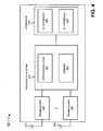
- Fig. 4 is a diagram of exemplary components of eNB 122-1.
- eNB 122-2 may be similarly configured.
- eNB 122-1 may include antennas 410.
- transceivers 420 may include antennas 410.
- transceivers 420 may include antennas 410.
- processing system 430 may include processing system 430.
- interface 440 may include interfaces 440.
- Antennas 410 may include one or more directional and/or omni-directional antennas.
- Transceivers 420 may be associated with antennas 410 and include transceiver circuitry for transmitting and/or receiving symbol sequences in a network, such as network 100. via antennas 410.
- Processing system 430 may control the operation of eNB 122-1. Processing system 430 may also process information received via transceivers 420 and interface 440. As illustrated, processing system 430 may include processing logic 432 and a memory 434. It will be appreciated that processing system 430 may include additional and/or different components than illustrated in Fig. 4 .
- Processing logic 432 may include a processor, microprocessor, an ASIC. FPGA. or the like. Processing logic 432 may process information received via transceivers 420 and interface 440. The processing may include, for example, data conversion, forward error correction (FEC), rate adaptation. Wideband Code Division Multiple Access (WCDMA) spreading/dispreading, and quadrature phase shift keying (QPSK) modulation, etc. In addition, processing logic 432 may generate control messages and/or data messages and cause those control messages and/or data messages to be transmitted via transceivers 420 and/or interface 440. Processing logic 432 may also process control messages and/or data messages received from transceivers 420 and/or interface 440. Memory 434 may include a RAM.
- Interface 440 may include one or more line cards that allow eNB 122-1 to transmit data to and receive data from other devices over wired and/or wireless connections. As illustrated, interface 440 may include an S1 interface 442 that allows eNB 122-1 to communicate, for example, with a MME/GW, such as MME/GW 132-1 and/or 132-2, and an X2 interface 444 that allows eNB 122-1 to communicate with another eNB. such as eNB 122-2.
- MME/GW such as MME/GW 132-1 and/or 132-2
- X2 interface 444 that allows eNB 122-1 to communicate with another eNB.
- eNB 122-1 may perform certain operations in response to processing logic 432 executing software instructions contained in a computer-readable medium, such as memory 434.
- a computer-readable medium may be defined as one or more physical and/or logical memory devices.
- the software instructions may be read into memory 434 from another computer-readable medium or from another device via interface 440.
- the software instructions contained in memory 434 may cause processing logic 432 to perform processes described herein.
- hardwired circuitry may be used in place of or in combination with software instructions to implement processes described herein.
- embodiments described herein are not limited to any specific combination of hardware circuitry and software.
- eNBs 122-1 may contain fewer, different, or additional components than depicted in Fig. 4 .
- one or more components of eNB 122-1 may perform the tasks described as being performed by one or more other components of eNB 122-1.
- Fig. 5 is a diagram of exemplary computer-readable media 500 and 530 that may be associated with eNB3 122-1. It will be appreciate that similar computer-readable media may be associated with eNBs 122-2. While two computer-readable media are described below, it will be appreciated that computer-readable media 500 and 530 may include additional computer-readable media stored locally at eNB 122-1 (e.g.. in memory 434), or stored at one or more different and possibly remote locations.
- computer-readable medium 500 may maintain a group of entries in the following exemplary fields: a UE identifier field 510 and a Radio Resource Management (RRM) Information (INFO) field 520.
- Computer-readable medium 500 may maintain additional or different information than illustrated in Fig. 5 .
- UE identifier field 510 may store a sequence of characters that identifies a UE, such as UE 110, associated with eNB 122-1. In one embodiment, the sequence of characters may be unique for that UE. For example, the sequence of characters may correspond to a network address.
- RRM INFO field 520 may store RRM information obtained by eNBs 122-1 for the UE identified in field 510. In one embodiment, the RRM information may include information relating to past and/or current radio resource usage of the particular UE.
- the RRM information may include information relating to the UE's scheduled uplink/downlink traffic, received/transmitted power levels, used resource blocks in time and/or in frequency, applied discontinuous reception/transmission (DRX) settings, used radio resources, a perceived quality of service of the UE, and/or other types of information that might be useful by a target eNB in determining a handover prediction for the UE.
- DRX discontinuous reception/transmission
- Computer-readable medium 530 may maintain a group of entries in the following exemplary fields: a Radio Bearer (RB) identifier field 540 and an RRM INFO field 550. Computer-readable medium 530 may maintain additional or different information than illustrated in Fig. 5 .
- RB Radio Bearer
- RB identifier field 540 may store a sequence of characters that identities a radio bearer associated with eNB 122-1. In one embodiment, the sequence of characters may be unique for that radio bearer with respect to eNB 122-1.
- RRM INFO field 550 may store RRM information obtained by eNB 122-1 for the radio bearer identified in field 510. In one embodiment, the RRM information may include information relating to activity levels, used radio resource blocks per Transmission Time Interval (TT1), used power levels per resource blocks, and/or other types of information that might be useful by a target eNB in determining a handover prediction for the UE.
- TT1 Transmission Time Interval
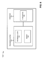
- Fig. 6 is a diagram of exemplary components of MME/GW 132-1.
- MME/GW 132-2 may be similarly configured.
- MME/GW 132-1 may include a processing system 610 and an interface 620.
- Processing system 610 may control the operation of MME/GW 132-1. Processing system 610 may also process information received via interface 620. As illustrated, processing system 610 may include processing logic 612 and a memory 614. It will be appreciated that processing system 610 may include additional and/or different components than illustrated in Fig. 6 .
- Processing logic 612 may include a processor, microprocessor, an ASIC, FPGA, or the like. Processing logic 612 may process information received via interface 620. In addition, processing logic 612 may generate control messages and/or data messages and cause those control messages and/or data messages to be transmitted via interface 620. Processing logic 612 may also process control messages and/or data messages received from interface 620.
- Memory 614 may include a RAM, a ROM, and/or another type of memory to store data and instructions that may be used by processing logic 612.
- Interface 620 may include one or more line cards that allow MME/GW 132-1 to transmit data to and receive data from other devices over wired and/or wireless connections.
- interface 620 may include an S1 interface 622 that allows MME/GW 132-1 to communicate, for example, with an eNB, such as eNB 122-1 and/or eNB 122-2.
- eNB such as eNB 122-1 and/or eNB 122-2.
- interface 620 may include additional interfaces than illustrated in Fig. 6 .
- interface 620 may include an interface for communicating with another network, such as a PDN.
- MME/GW 132-1 may perform certain operations in response to processing logic 612 executing software instructions contained in a computer-readable medium, such as memory 614.
- the software instructions may be read into memory 614 from another computer-readable medium or from another device via interface 620.
- the software instructions contained in memory 614 may cause processing logic 612 to perform processes described herein.
- hardwired circuitry may be used in place of or in combination with software instructions to implement processes described herein.
- embodiments described herein are not limited to any specific combination of hardware circuitry and software.
- MME/GW 132-1 may contain fewer, different, or additional components than depicted in Fig. 6 .
- one or more components of MME/GW 132-1 may perform the tasks described as being performed by one or more other components of MME/GW 132-1.
- Fig. 7 is a flowchart of an exemplary process for performing a handover.
- the processing described in Fig. 7 may be performed by eNB 122-1 (e.g., as a source eNB sewing a UE 110 via one or more non-Guaranteed Bit Rate (non-GBR) radio bearers or one or more GBR radio bearers for which the supported Maximum Bit Rate (MBR) is greater than the guaranteed bit rate) and eNB 122-2 (e.g., as a target eNB).
- eNB 122-1 e.g., as a source eNB sewing a UE 110 via one or more non-Guaranteed Bit Rate (non-GBR) radio bearers or one or more GBR radio bearers for which the supported Maximum Bit Rate (MBR) is greater than the guaranteed bit rate
- MBR Maximum Bit Rate
- some or all of the exemplary process described below may be performed by another device or combination of devices, including or excluding eNBs 122.
- source eNB 122-1 may collect RRM information that is specific to UE 110 and RRM information that is specific to the radio bearers associated with source eNB 122-1.
- source eNB 122-1 may collect RRM information for UE 110 during the time that UE 110 stays within a cell associated with source eNB 122-1.
- the UE-specific RRM information may include, for example, information relating to past and/or current radio resource usage of UE 110.
- the RRM information may include information relating to UE 110's scheduled uplink/downlink traffic, received/transmitted power levels, used resource blocks in time and/or in frequency, applied DRX settings, used radio resources, perceived quality of service of UE 110, and/or other types of information that might be useful by a target eNB in determining a handover prediction for UE 110.
- the radio bearer-specific RRM information may include, for example, information relating to activity levels of the radio bearers associated with UE 110, used radio resource blocks per TTI for the radio bearers, used power levels per resource blocks, and/or other types of information that might be useful by a target eNB in determining a handover prediction for UE 110.
- Source eNB 122-1 may store the UE-specific RRM information in a computer-readable medium, such as computer-readable medium 500.
- Source eNB 122-1 may further store the radio bearer-specific RRM information in a computer-readable medium, such as computer-readable medium 530.
- Source eNB 122-1 may determine that a handover should be initiated for UE 110 (block 710). In one embodiment, source eNB 122-1 may determine that a handover should be initiated based on measurement reports. For example, source eNB 122-1 may command UE 110 to perform measurements, generate measurement reports, and transmit the measurement reports to source eNB 122-1. In other embodiments, source eNB 122-1 may determine that a handover should be initiated for UE 110 based on other information.
- source eNB 122-1 may create a handover request message (block 715).
- the handover request message may include RRM information relating to UE 110 (e.g.. UE-specitic RRM information and/or radio bearer-specific RRM information).
- the handover request message may include the HANDOVER REQUEST message defined in 3GPP TS 36.423.
- the RRM information may be provided, for example, in the UE History Information Element (IE) of the HANDOVER REQUEST message.
- source eNB 122-1 may transfer the handover request message to target eNB 122-2 (block 715).
- Source eNB 122-1 may transfer the handover request message over the X2 interface.
- Target eNB 122-2 may receive the handover request (block 720) and, in response thereto, may identify current network information for target eNB 122-2 (block 725).
- the current network information may include target eNB 122-2's current resource situation, such as information relating to target eNB 122-2's current capacity situation and/or current load situation.
- Target eNB 122-2 may generate handover feedback information for UE 110 based on the RRM information received in the handover request and based on the identified current network information for target eNB 122-2 (block 730).
- the handover feedback information may include, for example, an indication that, based on the received RRM information and the identified current network information for target eNB 122-2, target eNB 122-2 may not be able to support the same activity level for UE 110 as source eNB 122-1.
- the indication may be provided as a degradation level.
- a "1" may indicate that there is low risk or degraded performance; a “2" may indicate that there is medium risk of degraded performance; and a “3" may indicate that there is a high risk of degraded performance, where source eNB 122-1 is strongly advised to modify activity levels of UE 110. if possible.
- the handover feedback information may identify the radio bearers that may receive less radio resources than provided by source eNB 122-1. Also, the handover feedback information may indicate the activity (e.g. in terms of supported packet delay, throughput. etc.) that target eNB 122-2 may be able to support.
- Target eNB 122-2 may create a handover response message (block 735).
- the handover response message may include the handover feedback information.
- the handover response message may be created as the HANDOVER REQUEST ACKNOWLEDGE message defined in 3GPP TS 36.423.
- the HANDOVER REQUEST ACKNOWLEDGE message format may be modified, however, to include the handover feedback information generated by target eNB 122-2.
- target eNB 122-2 may include a Handover (IIO) Evaluation Assistance Data IE that includes the handover feedback information.
- the handover feedback information may be included within the Target-eNB-to-Source-eNB Transparent Container IE.
- HO EVALUATION ASSISTANCE DATA IE IE/Group Name Presence Range IE type and reference Semantics description Performance Degradation Indication O INTEGER (1..3) Indication that the current UE activity level might not be supported in the target cell Degradation levels: 1: low risk of degraded performance: 2: medium risk of degraded performance: 3 : high risk of degraded performance, source eNB strongly advised to modify UE activity levels if possible:
- target eNB 122-2 may create another type of message in response to receiving a handover request message.
- target eNB 122-2 may create a handover response message that includes Mobility control information, as defined by 3GPP TS 36.331.
- Mobility control information includes the handover feedback information
- Table 3 An exemplary format of the Mobility control information (including the handover feedback information) is illustrated in Table 3 below.
- Table 3 An exemplary format of the Mobility control information (including the handover feedback information) is illustrated in Table 3 below. Table 3.
- MOBILITY CONTROL INFORMATION Name Need Multi Type/ reference Semantics description Ver Target cell identity MP ⁇ ref> Carrier frequency oc ⁇ ref> Additional spectrum emission requirement oc Integer (1..31) Defined in [36.101]
- Target eNB 122-2 may transfer the handover response message to source eNB 122-1 (block 735). Target eNB 122-2 may transfer the handover response message over the X2 interface.
- Source eNB 122-1 may receive the handover response message (block 740).
- Source eNB 122-1 may parse the handover response message to identify the handover feedback information.
- Source eNB 122-1 may perform a number of actions based on the received handover feedback information. For example, source eNB 122-1 may determine, based on the handover feedback information received from target eNB 122-2, that another target eNB, for which prepared handover exists, is better suited for the handover (block 745). As a result, source eNB 122-1 may handover UE 110 to another, better-suited target eNB.
- source eNB 122-1 may modify the scheduling strategy for which UE 110 communicates with source eNB 122-1 to adapt UE 110 to the resource capability of target eNB 122-2 (block 750). Thereafter, UE 110 may communicate with source eNB 122-1 according to the modified scheduling strategy. When the handover to target 122-2 occurs, the user associated with UE 110 may not notice degradation in performance.
- source eNB 122-1 may send a command to UE 110 to cause UE 110 to reconfigure one or more ongoing services (block 755). For example, assume
- Source eNB 122-1 may send a command to UE 110 that causes UE 110 to reconfigure one or more of the settings of the game (e.g., to consume less resources).
- UE 110 may perform actions where the lower layers of UE I 10's protocol stack (e.g., that part of the protocol stack that handles radio communication) interact with the upper layers of the protocol stack (e.g., the non-access stratum/service layer) to reconfigure one or more characteristics of the application being run on UE 110 (e.g., to consume less resources).
- the handover to target eNB 122-2 occurs, the user associated with UE 110 may not notice degradation in service.
- source eNB 122-1 may send a degradation warning to UE 110 (block 760).
- source eNB 122-1 may cause a message to be displayed on UE 110 to warn the user that degradation in service is forthcoming.
- the message may further include one or more actions that the user may perform to reduce the amount of degradation of performance that the user will experience, such as changing one or more characteristics of an application currently running on UE 110.
- source eNB 122-1 may perform a combination of the actions described above. Also, source eNB 122-1 may perform actions in addition to or as an alternative to those described above.
- target eNB 122-2 may transmit a handover failure message to source eNB 122-1.
- the handover failure message may include the generated handover feedback information.
- the handover failure message may be created as a HANDOVER PREPARATION FAILURE message, which includes the HO Evaluation Assistance Data IE.
- An exemplary format of the modified HANDOVER PREPARATION FAILURE message (including the HO Evaluation Assistance Data IE) is provided below in Table 4. Table 4.
- Figs. 8A-11C are examples of the processing described above with respect to Fig. 7 .
- a UE 110 is currently supported by a source eNB 122-1 and that source eNB 122-1 determines that a handover is to be initiated for UE 110.
- source eNB 122-1 may send handover requests 805 to possible target eNBs (denoted as target eNB 122-2 and target eNB 122-3 in example 800).
- Handover requests 805 may include RRM information (e.g., the UE-specific RRM information and the radio bearer-specific RRM information described above).
- Target eNBs 122-2 and 122-3 may receive handover requests 805 and may, based on the RRM information included in handover requests 805, generate handover feedback information.
- target eNB 122-2 generates handover feedback information that indicates that a high risk of degraded performance for UE 110 is likely if the handover to target eNB 122-2 is performed.
- target eNB 122-3 generates handover feedback information that indicates that a low risk of degraded performance for UE 110 is likely if the handover to target eNB 122-3 is performed.
- Target eNB 122-2 may transmit a handover response 810 that includes its feedback information to source eNB 122-1, as illustrated in Fig. 8B .
- Target eNB 122-3 may also transmit a handover response 815 that includes its feedback information to source eNB 122-1.
- source eNB 122-1 may determine that, although a handover to both target eNB 122-2 and target eNB 122-3 are possible, a handover to target eNB 122-3 would be preferential, due to a likelihood of less degradation in performance experienced by the user of UE 110. Accordingly, source eNB 122-1 may transmit a handover command 820 to UE 110 to cause UE to begin communication 825 with target eNB 122-3. as illustrated in Fig. 8C .
- source eNB 122-1 may send a handover request 905 to target eNB 122-2.
- Handover request 905 may include RRM information (e.g., the UE-specific RRM information and the radio bearer-specific RRM information described above).
- Target eNB 122-2 may receive handover request 905 and may, based on the RRM information included in handover request 905. generate handover feedback information.
- target eNB 122-2 generates handover feedback information that indicates that a risk of degraded performance for UE 110 is likely if the handover to target eNB 122-2 is performed.
- Target eNB 122-2 may transmit a handover response 910 that includes the feedback information to source eNB 122-1.
- source eNB 122-1 may modify the scheduling strategy with which UE 110 communicates with source eNB 122-1.
- the modified scheduling strategy may be an attempt by source eNB 122-1 to adapt UE 110 to the communication performance that UE 110 will receive at target eNB 122-2.
- UE 110 may communicate 915 with source eNB 122-1 according to the modified scheduling strategy.
- Source eNB 122-1 may transmit a handover command 920 to UE 110 ( Fig. 9B ) to cause UE to begin communication 925 with target eNB 122-2 (e.g.. using the modified scheduling strategy), as illustrated in Fig. 9C .
- source eNB 122-1 may send a handover request 1005 to target eNB 122-2.
- Handover request 1005 may include RRM information (e.g., the UE-specific RRM information and the radio bearer-specific RRM information described above).
- Target eNB 122-2 may receive handover request 1005 and may, based on the RRM information included in handover request 1005. generate handover feedback information.
- target eNB 122-2 may transmit a handover response 1010 that includes the feedback information to source eNB 122-1.
- source eNB 122-1 may send a handover command 1015 to UE 110 that includes a command to cause UE 110 to reconfigure one or more ongoing services.
- source eNB 122-1 may cause UE 110 to alter the settings of one or more applications currently running on UE 110 to, for example, cause the applications to consume less resources.
- the handover command may be separate from the command to cause UE 110 to reconfigure one or more ongoing services.
- UE 110 may reconfigure one or more ongoing services and begin communication 1020 with target eNB 122-2 (e.g., using the reconfigured ongoing service), as illustrated in Fig. 10B .
- source eNB 122-1 may send a handover request 1105 to target eNB 122-2.
- Handover request 1105 may include RRM information (e.g., the UE-specitic RRM information and the radio bearer-specific RRM information described above).
- Target eNB 122-2 may receive handover request 1105 and may, based on the RRM information included in handover request 1105, generate handover feedback information.
- RRM information e.g., the UE-specitic RRM information and the radio bearer-specific RRM information described above.
- Target eNB 122-2 may receive handover request 1105 and may, based on the RRM information included in handover request 1105, generate handover feedback information.
- target eNB 122-2 generates handover feedback information that indicates that a risk of degraded performance for UE 110 is likely if the handover to target eNB 122-2 is performed.
- Target eNB 122-2 may transmit a handover response 1110 that includes the feedback information to source eNB 122-1.
- source eNB 122-1 may send a degradation warning and handover command 1115 to UE 110.
- the handover command may be separate from the degradation warning.
- the degradation warning may cause a message 1120 to be displayed to a user associated with UE 110, as illustrated in Fig. 11B .
- Message 1120 may indicate that degradation in performance is likely and may, for example, indicate one or more actions that the user may perform to reduce the likelihood of degradation in performance.
- UE 110 may begin communication 1125 with target eNB 122-2, as illustrated in Fig. 11C (e.g., before or after the user performing the one or more actions).
- Fig. 12 is a flowchart of another exemplary process for performing a handover.
- the processing described in Fig. 12 may be performed by MME/GW 132-1 and eNB 122-2 (e.g., as a target eNB).
- some or all of the exemplary process described below may be performed by another device or combination of devices, including or excluding MME/GW 132-1 and eNB 122-2.
- the exemplary process may begin with MME/GW 132-1 receiving a handover request message for a UE (assumed as UE 110) from a source eNB (assumed to be eNB 122-1) (block 1205).
- the handover request message may include RRM information (e.g.. UE-specific RRM information and radio bearer-specific RRM information).
- the handover request message may include, for example, the HANDOVER REQUIRED message defined in 3GPP TS 36.413.
- MME/GW 132-1 may receive the handover request message over the S 1 interface.
- MME/GW 132-1 may send a handover request message, which includes the RRM information, to target eNB 122-2 (block 1210).
- the handover request message may include the HANDOVER REQUEST message defined in 3GPP TS 36.413.
- MME/GW 132-1 may transfer the handover request message over the S1 interface.
- Target eNB 122-2 may receive the handover request message (block 1215) and, in response thereto, may identify current network information for target eNB 122-2 (block 1220).
- the current network information may include target eNB 122-2's current resource situation, such as information relating to target eNB 122-2's current capacity situation and/or current load situation.
- Target eNB 122-2 may generate handover feedback information for UE 110 based on the RRM information received in the handover request and based on the identified current network information for target eNB 122-2 (block 1225).
- the handover feedback information may include, for example, an indication that, based on the received RRM information and the identified current network information for target eNB 122-2, target eNB 122-2 may not be able to support the same activity level for UE 110 as source eNB 122-1.
- the indication may be provided as a degradation level.
- the handover feedback information may identify the radio bearers that may receive less radio resources than provided by source eNB 122-1. Also, the handover feedback information may indicate the activity (e.g. in terms of supported packet delay, throughput, etc.) that target eNB 122-2 may be able to support.
- Target eNB 122-2 may create a handover response message (block 1230).
- the handover response message may include the handover feedback information.
- the handover response message may be created as the HANDOVER REQUEST ACKNOWLEDGE message defined in 3GPP TS 36.413.
- the HANDOVER REQUEST ACKNOWLEDGE message format may be modified in a manner similar to the manner described above to include the handover feedback information generated by target eNB 122-2.
- Target eNB 122-2 may transfer the handover response message to MME/GW 132-1 (block 1230). Target eNB 122-2 may transfer the handover response message over the S I interface.
- MME/GW 132-1 may receive the handover response message (block 1235). In response, MME/GW 132-1 may create a handover command based on the contents of the handover response message (block 1240). In one embodiment, the handover command may be created as a HANDOVER COMMAND message, as defined in 3GPP TS 36.413. The HANDOVER COMMAND message format may be modified in a manner similar to the manner described above with respect to the HANDOVER REQUEST ACKNOWLEDGE message to include the handover feedback information generated by target eNB 122-2. MME/GW 132-1 may send the handover command to source eNB 122-1 (block 1240). Upon receipt of the handover command from MME/GW 132-1, source eNB 122-1 may perform one or more of the actions described above with respect to Fig. 7 .
- Embodiments described herein may include systems and/or methods that predict the likelihood of a UE receiving the same quality of service at a target node, after handover, that the UE is currently receiving at the source node.
- the source node may gather current activity and resource usage information about individual UEs (called UE-specific RRM information) that provide more fine grained information than the associated radio bearer parameters.
- UE-specific RRM information current activity and resource usage information about individual UEs
- This advantage may be applicable for both non-GBR and GBR bearers for which the maximum (or peak) bit rate is greater than the GBR (MBR>GBR).
- MBR maximum (or peak) bit rate
- the target node can have more precise information and finer grained pieces of information about the actual resource requirements of the UE than what the target node can obtain from the radio bearer-specific RRM information alone.
- the target node can use this information to provide a prediction to the source node that indicates the likelihood of the UE receiving the same QoS in the new cell (i.e.. the cell provided by the target node) after handover.
- the target node may also provide handover feedback information in case the handover preparation fails.
- the source node's handover decisions may be helped with up-to-date information about the target node's resource situation, and not just by background load information which could be obsolete at the time of handover.
- the source node can send a warning pro-actively to UEs running best effort (non GBR) or elastic (MBR>GBR) applications.
- the warning may indicate that although the target node is able to commit to a minimum bit rate and QoS, degradation in the perceived QoS is likely to happen after handover execution.
- the UE can, for example, use this information in cross layer signaling to the application layer. As a result, the UE may have a higher chance of continuing to receive the service in a cell with resource issues, by reconfiguring (and adapting to the new resource situation) in due time prior to handover.
- Embodiments described herein provide illustration and description, but are not intended to be exhaustive or to limit the implementations to the precise form disclosed. Modifications and variations are possible in light of the above teachings, or may be acquired from practice of the embodiments.
- the techniques described above relate to providing handover feedback information from the target node to a source node during the handover execution, in other embodiments, the handover feedback information may be provided at other times (e.g., as part of a re-negotiation process).
- the exemplary embodiments may be implemented in many different forms or software, firmware, and hardware in the embodiments illustrated in the figures.
- the actual software code or specialized control hardware used to implement the exemplary embodiments described herein is not limiting of the invention.
- the operation and behavior of the exemplary embodiments were described without reference to the specific software code - it being understood that one would be able to design software and control hardware to implement the exemplary embodiments based on the description herein.
- logic may include hardware, such as an application specific integrated circuit, a field programmable gate array, a processor, or a microprocessor, or a combination of hardware and software.
Description
- Embodiments described herein relate generally to wireless networks, and more particularly, to making handover decisions based on prediction information from a target node in a wireless network.
- Traditionally, admission control at handover is exercised by a target cell based on Quality of Service (QoS) requirements of a radio bearer(s) of user equipment (UE) and the target cell's resource situation. To this end, the cellular standards specify signaling messages between base stations and/or the associated radio network controllers that allow radio bearer information to be conveyed from one cell to another. For radio bearers with no QoS guarantees (i.e., without a Guaranteed Bit Rate (GBR)), the target cell does not exercise admission control. In fact, non-GBR radio bearers are always admitted upon handover by the target cell and subsequently treated on a best effort basis (i.e.. without reserving radio, transport. hardware/software, and/or other types of resources).
- For example, in the Evolved Universal Terrestrial Radio Access Network (E-UTRAN), during Handover Preparation, a source base station (called an evolved Node B (eNB)) can convey radio bearer-specific Radio Resource Management (RRM) information to a target base station (eNB) over an X2 interface. The radio bearer-specific RRM information may include information relating to past and current radio resource usage of particular user equipment (UE).
- The target base station does not. however, take into account the actual resource need(s) of the newly arriving UE and does not reserve resources for best effort services. As such, the present typical so called "best effort" scheme is in fact not a best effort in the sense that the perceived QoS and the provided radio resources are not maximized for the UE that is handed over to the target base station. This is because the target base station uses the available signaled QoS parameters associated with the radio bearers of the UE (which may be limited to the currently standardized QoS parameters).
- Thus, the source base station may direct a UE to a target cell that is not able to provide the appropriate service level for ongoing sessions associated with the particular UE. For example, if a UE is using non-GBR (best effort) services, a target cell with limited resources may be selected for handover even when another target cell with an abundance of resources could accommodate the UE.
-
US 2007/258406 A1 discloses a method for carrying out a handover including sending and handover request to a target node, where said handover request includes information regarding signal strength and traffic load. - It is an object of the invention to overcome at least some of the above disadvantages and to provide improved handover processing.
- Embodiments described herein include systems and methods that predict the likelihood of a UE receiving the same quality of service at a target node, after handover, that the UE is currently receiving as the source node. The source node gathers current activity and resource usage information about individual UEs (called UE-specific RRM information) that provide more fine grained information than the associated radio bearer parameters. This advantage may be applicable for both non-GBR and GBR bearers for which the maximum (or peak) bit rate is greater than the GBR (MBR>GBR). In the latter case, there may be a huge difference between a source cell and a target cell in terms of the actually supported bit rate (e.g., the source cell may be close to MBR, while the target cell may be close to GBR).
- The target node can have more precise information and finer grained pieces of information about the actual resource requirements of the UE than what the target node can obtain from the radio bearer-specific RRM information alone. The target node can use this information to provide a prediction to the source node that indicates the likelihood of the UE receiving the same QoS in the new cell (i.e., the cell provided by the target node) after handover. The target node may also provide handover feedback information in case handover preparation fails. Thus, the source node's handover decisions may be helped with up-to-date information about the target node's resource situation, and not just by background load information which could be obsolete at the time of handover.
- In one embodiment, the source node can send a warning pro-actively to UEs running best effort (non GBR) or elastic (MBR>GBR) applications. The warning may indicate that although the target node is able to commit to a minimum bit rate and QoS, degradation in the perceived QoS is likely to happen after handover execution. The UE can, for example, use this information in cross layer signaling to the application layer. As a result, the UE may have a higher chance of continuing to receive the service in a cell with resource issues, by reconfiguring (and adapting to the new resource situation) in due time prior to handover.
- In an exemplary embodiment, a system described herein includes a source node to collect radio resource management (RRM) information, determine that a handover is to be initiated for user equipment (UE), and send, in response to the determination that a handover is to be initiated, a handover request message that includes the RRM information. The system further includes a target node to receive the handover request message from the source node, identify, in response to receiving the handover request message, current network information for the target node, generate handover feedback information for the UE based on the RRM information and the identified current network information, and send a handover response message to the source node. The handover response message includes the generated handover feedback information. The generated handover feedback information assists the source node in making a decision regarding the handover.
-
-
Fig. 1 is a diagram of anexemplary network 100 in which systems and methods described herein may be implemented; -
Fig. 2 is a diagram of an exemplary implementation of the UE ofFig. 1 ; -
Fig. 3 is a diagram of exemplary components of the UE ofFig. 2 ; -
Fig. 4 is a diagram of exemplary components of the evolved Node B (eNB) ofFig. 1 ; -
Fig. 5 is a diagram of exemplary computer-readable media that may be associated with the eNB ofFig. 1 ; -
Fig. 6 is a diagram of exemplary components of the Mobility Management Entity (MME)/Gateway (GW) ofFig. 1 ; -
Fig. 7 is a flowchart of an exemplary process for performing a handover; -
Figs. 8A-11C are examples of the processing described above with respect toFig. 7 ; and -
Fig. 12 is a flowchart of another exemplary process for performing a handover. - The following detailed description refers to the accompanying drawings. The same reference numbers in different drawings may identify the same or similar elements. Also, the following detailed description does not limit the invention.
- Embodiments described herein provide improved handover in a wireless network. In one embodiment, a source node, in response to determining that a handover is to be initiated for UE, may transfer RRM information to a target node. The target node may use the RRM information, along with current network information associated with the target node, to generate handover feedback information for the UE. The target node may transfer the handover feedback information to the source node. The source node may use that handover feedback information as a prediction of the likelihood that the services currently running on the UE can be maintained with the same level of QoS in the new cell (i.e., the cell supported by the target node), after the handover.
-
Fig. 1 is a diagram of anexemplary network 100 in which systems and methods described herein may be implemented. As illustrated,network 100 may include user equipment (UE) 110, an Evolved Universal Terrestrial Radio Access Network (E-UTRAN) 120, and an Evolved Packet Core (EPC) 130. The number of components illustrated inFig. 1 is provided for simplicity. In practice,network 100 may include additional and/or different components than illustrated inFig. 1 . - UE 110 may include one or more devices capable of sending/receiving traffic (e.g.. voice and/or data) to/from E-UTRAN 120. In one embodiment. UE 110 may include, for example, a wireless telephone, a personal digital assistant (PDA), a laptop, etc.
- E-UTRAN 120 may include a network, as defined, for example, in the 3rd Generation Partnership Project (3GPP) Technical Specification (TS) 36.300, via which UE 110 may communicate. As illustrated, E-UTRAN 120 may include a group of evolved Node Bs (eNBs) 122-1 to 122-2 (referred to collectively as "eNBs 122"). Two eNBs 122 have been illustrated for simplicity. In practice, there may be more eNBs.
- eNBs 122 (also referred to as base stations) may include one or more devices that receive traffic (e.g., voice and/or data) from
UE 110 via an air interface, and transmit traffic (e.g., voice and/or data) toUE 110 via the air interface. In one embodiment, eNB 122-1 may communicate with eNB 122-2 via an X2 interface. - EPC 130 may include a network that receives traffic (e.g., packet-switched traffic) from E-UTRAN 120 and forwards the traffic to another network, such as a Public Data Network (PDN) like the Internet, and receives traffic from the other network and forwards the traffic to E-UTRAN 120. As illustrated, EPC 130 may include a group of Mobility Management Entities (MMEs)/Gateways (GWs) 132-1 through 132-2 (referred to collectively as "MMEs/GWs 132"). Two MMEs/GWs 132 have been illustrated for simplicity. In practice, there may be more MMEs/GWs.
- Each MME/GW 132-1 through 132-2 may include an MME and a GW. The MME may include one or more devices that manage mobility of
UE 110. MME may further include one or more devices that perform authentication and authorization, idle-mode UE tracking and reachability, security negotiations, and Network-Architecture Specific (NAS) signaling. The GW may include one or more devices that receive/forward traffic from/to eNBs 122. The GW may further include one or more devices that act as interfaces to external PDNs. MME/GW 132-1 and MME/GW 132-2 may communicate with eNB 122-1 and eNB 122-2 viaS 1 interfaces. -
Fig. 2 is a diagram of an exemplary implementation ofUE 110. In the example illustrated inFig. 2 .UE 110 is implemented as a cell phone.UE 110 may include amicrophone 210, aspeaker 220, a group ofinput elements 230, and adisplay 240. -
Microphone 210 may receive audible information from a user ofUE 110.Speaker 220 may provide audible information to a user ofUE 110.Input elements 230 may include control buttons and/or a keypad. The control buttons may permit a user to interact withUE 110 to causeUE 110 to perform one or more operations. For example, the control buttons may be used to causeUE 110 to transmit information. The keypad may include a standard telephone keypad.Display 240 may provide visual information to a user. For example,display 240 may display text input intoUE 110, text and/or graphics received from another device, such as eNB 122-1. and/or information regarding incoming or outgoing calls or text messages, media, games, phone books, address books, the current time, etc. - Although
Fig. 2 shows exemplary components ofUE 110, in other implementations.UE 110 may contain fewer, different, or additional components than depicted inFig. 2 . In still other implementations, one or more components ofUE 110 may perform the tasks described as being performed by one or more other components ofUE 110. -
Fig. 3 is a diagram of exemplary components ofUE 110 ofFig. 2 . As illustrated,UE 110 may include anantenna 310, atransceiver 320,processing logic 330, amemory 340, an input device(s) 350, an output device(s) 360, and a bus 370. -
Antenna 3 10 may include one or more antennas to transmit and/or receive radio frequency (RF) signals over the air.Antenna 310 may, for example, receive RF signals fromtransceiver 320 and transmit the RF signals over the air to eNB 122-1 and receive RF signals over the air from eNB 122-1 and provide the RF signals totransceiver 320. -
Transceiver 320 may include, for example, a transmitter that may convert baseband signals from processinglogic 330 to RF signals and/or a receiver that may convert RF signals to baseband signals. Alternatively,transceiver 320 may include a transceiver to perform functions of both a transmitter and a receiver.Transceiver 320 may connect toantenna 310 for transmission and/or reception of the RF signals. -
Processing logic 330 may include a processor, microprocessor, an application specific integrated circuit (ASIC), field programmable gate array (FPGA), or the like.Processing logic 330 may control operation ofUE 110 and its components. -
Memory 340 may include a random access memory (RAM), a read only memory (ROM), and/or another type of memory to store data and instructions that may be used by processinglogic 330. Input device(s) 350 may include mechanisms for entry of data intoUE 110. For example, input device(s) 350 may include input mechanisms, such asmicrophone 210,input elements 230,display 240, etc. Output device(s) 360 may include mechanisms for outputting data in audio, video and/or hard copy format. For example, output device(s) 360 may includespeaker 220.display 240, etc. Bus 370 may interconnect the various components ofUE 110 to permit the components to communicate with one another. - Although
Fig. 3 shows exemplary components ofUE 110. in other implementations.UE 110 may contain fewer, different, or additional components than depicted inFig. 3 . In still other implementations, one or more components ofUE 110 may perform the tasks described as being performed by one or more other components ofUE 110. -
Fig. 4 is a diagram of exemplary components of eNB 122-1. eNB 122-2 may be similarly configured. As illustrated, eNB 122-1 may includeantennas 410.transceivers 420, aprocessing system 430. and aninterface 440. -
Antennas 410 may include one or more directional and/or omni-directional antennas.Transceivers 420 may be associated withantennas 410 and include transceiver circuitry for transmitting and/or receiving symbol sequences in a network, such asnetwork 100. viaantennas 410. -
Processing system 430 may control the operation of eNB 122-1.Processing system 430 may also process information received viatransceivers 420 andinterface 440. As illustrated,processing system 430 may includeprocessing logic 432 and amemory 434. It will be appreciated thatprocessing system 430 may include additional and/or different components than illustrated inFig. 4 . -
Processing logic 432 may include a processor, microprocessor, an ASIC. FPGA. or the like.Processing logic 432 may process information received viatransceivers 420 andinterface 440. The processing may include, for example, data conversion, forward error correction (FEC), rate adaptation. Wideband Code Division Multiple Access (WCDMA) spreading/dispreading, and quadrature phase shift keying (QPSK) modulation, etc. In addition,processing logic 432 may generate control messages and/or data messages and cause those control messages and/or data messages to be transmitted viatransceivers 420 and/orinterface 440.Processing logic 432 may also process control messages and/or data messages received fromtransceivers 420 and/orinterface 440.Memory 434 may include a RAM. a ROM, and/or another type of memory to store data and instructions that may be used by processinglogic 432.Interface 440 may include one or more line cards that allow eNB 122-1 to transmit data to and receive data from other devices over wired and/or wireless connections. As illustrated,interface 440 may include anS1 interface 442 that allows eNB 122-1 to communicate, for example, with a MME/GW, such as MME/GW 132-1 and/or 132-2, and anX2 interface 444 that allows eNB 122-1 to communicate with another eNB. such as eNB 122-2. - eNB 122-1 may perform certain operations in response to
processing logic 432 executing software instructions contained in a computer-readable medium, such asmemory 434. A computer-readable medium may be defined as one or more physical and/or logical memory devices. The software instructions may be read intomemory 434 from another computer-readable medium or from another device viainterface 440. The software instructions contained inmemory 434 may causeprocessing logic 432 to perform processes described herein. Alternatively, hardwired circuitry may be used in place of or in combination with software instructions to implement processes described herein. Thus, embodiments described herein are not limited to any specific combination of hardware circuitry and software. - Although
Fig. 4 shows exemplary components of eNB 122-1, in other implementations, eNBs 122-1 may contain fewer, different, or additional components than depicted inFig. 4 . In still other implementations, one or more components of eNB 122-1 may perform the tasks described as being performed by one or more other components of eNB 122-1. -
Fig. 5 is a diagram of exemplary computer-readable media readable media - As illustrated, computer-
readable medium 500 may maintain a group of entries in the following exemplary fields: aUE identifier field 510 and a Radio Resource Management (RRM) Information (INFO)field 520. Computer-readable medium 500 may maintain additional or different information than illustrated inFig. 5 . -
UE identifier field 510 may store a sequence of characters that identifies a UE, such asUE 110, associated with eNB 122-1. In one embodiment, the sequence of characters may be unique for that UE. For example, the sequence of characters may correspond to a network address.RRM INFO field 520 may store RRM information obtained by eNBs 122-1 for the UE identified infield 510. In one embodiment, the RRM information may include information relating to past and/or current radio resource usage of the particular UE. For example, the RRM information may include information relating to the UE's scheduled uplink/downlink traffic, received/transmitted power levels, used resource blocks in time and/or in frequency, applied discontinuous reception/transmission (DRX) settings, used radio resources, a perceived quality of service of the UE, and/or other types of information that might be useful by a target eNB in determining a handover prediction for the UE. - Computer-
readable medium 530 may maintain a group of entries in the following exemplary fields: a Radio Bearer (RB)identifier field 540 and anRRM INFO field 550. Computer-readable medium 530 may maintain additional or different information than illustrated inFig. 5 . -
RB identifier field 540 may store a sequence of characters that identities a radio bearer associated with eNB 122-1. In one embodiment, the sequence of characters may be unique for that radio bearer with respect to eNB 122-1.RRM INFO field 550 may store RRM information obtained by eNB 122-1 for the radio bearer identified infield 510. In one embodiment, the RRM information may include information relating to activity levels, used radio resource blocks per Transmission Time Interval (TT1), used power levels per resource blocks, and/or other types of information that might be useful by a target eNB in determining a handover prediction for the UE. -
Fig. 6 is a diagram of exemplary components of MME/GW 132-1. MME/GW 132-2 may be similarly configured. As illustrated, MME/GW 132-1 may include aprocessing system 610 and aninterface 620. -
Processing system 610 may control the operation of MME/GW 132-1.Processing system 610 may also process information received viainterface 620. As illustrated,processing system 610 may includeprocessing logic 612 and amemory 614. It will be appreciated thatprocessing system 610 may include additional and/or different components than illustrated inFig. 6 . -
Processing logic 612 may include a processor, microprocessor, an ASIC, FPGA, or the like.Processing logic 612 may process information received viainterface 620. In addition,processing logic 612 may generate control messages and/or data messages and cause those control messages and/or data messages to be transmitted viainterface 620.Processing logic 612 may also process control messages and/or data messages received frominterface 620.Memory 614 may include a RAM, a ROM, and/or another type of memory to store data and instructions that may be used by processinglogic 612. -
Interface 620 may include one or more line cards that allow MME/GW 132-1 to transmit data to and receive data from other devices over wired and/or wireless connections. As illustrated,interface 620 may include anS1 interface 622 that allows MME/GW 132-1 to communicate, for example, with an eNB, such as eNB 122-1 and/or eNB 122-2. It will be appreciated thatinterface 620 may include additional interfaces than illustrated inFig. 6 . For example,interface 620 may include an interface for communicating with another network, such as a PDN. - MME/GW 132-1 may perform certain operations in response to
processing logic 612 executing software instructions contained in a computer-readable medium, such asmemory 614. The software instructions may be read intomemory 614 from another computer-readable medium or from another device viainterface 620. The software instructions contained inmemory 614 may causeprocessing logic 612 to perform processes described herein. Alternatively, hardwired circuitry may be used in place of or in combination with software instructions to implement processes described herein. Thus, embodiments described herein are not limited to any specific combination of hardware circuitry and software. - Although
Fig. 6 shows exemplary components of MME/GW 132-1. in other implementations, MME/GW 132-1 may contain fewer, different, or additional components than depicted inFig. 6 . In still other implementations, one or more components of MME/GW 132-1 may perform the tasks described as being performed by one or more other components of MME/GW 132-1. -
Fig. 7 is a flowchart of an exemplary process for performing a handover. In one embodiment, the processing described inFig. 7 may be performed by eNB 122-1 (e.g., as a source eNB sewing aUE 110 via one or more non-Guaranteed Bit Rate (non-GBR) radio bearers or one or more GBR radio bearers for which the supported Maximum Bit Rate (MBR) is greater than the guaranteed bit rate) and eNB 122-2 (e.g., as a target eNB). In another embodiment, some or all of the exemplary process described below may be performed by another device or combination of devices, including or excluding eNBs 122. - The exemplary process may begin with source eNB 122-1 collecting RRM information (block 705). In one embodiment, source eNB 122-1 may collect RRM information that is specific to
UE 110 and RRM information that is specific to the radio bearers associated with source eNB 122-1. For example, source eNB 122-1 may collect RRM information forUE 110 during the time that UE 110 stays within a cell associated with source eNB 122-1. The UE-specific RRM information may include, for example, information relating to past and/or current radio resource usage ofUE 110. For example, the RRM information may include information relating toUE 110's scheduled uplink/downlink traffic, received/transmitted power levels, used resource blocks in time and/or in frequency, applied DRX settings, used radio resources, perceived quality of service ofUE 110, and/or other types of information that might be useful by a target eNB in determining a handover prediction forUE 110. The radio bearer-specific RRM information may include, for example, information relating to activity levels of the radio bearers associated withUE 110, used radio resource blocks per TTI for the radio bearers, used power levels per resource blocks, and/or other types of information that might be useful by a target eNB in determining a handover prediction forUE 110. Source eNB 122-1 may store the UE-specific RRM information in a computer-readable medium, such as computer-readable medium 500. Source eNB 122-1 may further store the radio bearer-specific RRM information in a computer-readable medium, such as computer-readable medium 530. - Source eNB 122-1 may determine that a handover should be initiated for UE 110 (block 710). In one embodiment, source eNB 122-1 may determine that a handover should be initiated based on measurement reports. For example, source eNB 122-1 may command
UE 110 to perform measurements, generate measurement reports, and transmit the measurement reports to source eNB 122-1. In other embodiments, source eNB 122-1 may determine that a handover should be initiated forUE 110 based on other information. - In response to determining that a handover should be initiated for
UE 110, source eNB 122-1 may create a handover request message (block 715). The handover request message may include RRM information relating to UE 110 (e.g.. UE-specitic RRM information and/or radio bearer-specific RRM information). In one embodiment, the handover request message may include the HANDOVER REQUEST message defined in 3GPP TS 36.423. The RRM information may be provided, for example, in the UE History Information Element (IE) of the HANDOVER REQUEST message. Once created, source eNB 122-1 may transfer the handover request message to target eNB 122-2 (block 715). Source eNB 122-1 may transfer the handover request message over the X2 interface. - Target eNB 122-2 may receive the handover request (block 720) and, in response thereto, may identify current network information for target eNB 122-2 (block 725). In one embodiment, the current network information may include target eNB 122-2's current resource situation, such as information relating to target eNB 122-2's current capacity situation and/or current load situation.
- Target eNB 122-2 may generate handover feedback information for
UE 110 based on the RRM information received in the handover request and based on the identified current network information for target eNB 122-2 (block 730). The handover feedback information may include, for example, an indication that, based on the received RRM information and the identified current network information for target eNB 122-2, target eNB 122-2 may not be able to support the same activity level forUE 110 as source eNB 122-1. In one embodiment, the indication may be provided as a degradation level. For example, a "1" may indicate that there is low risk or degraded performance; a "2" may indicate that there is medium risk of degraded performance; and a "3" may indicate that there is a high risk of degraded performance, where source eNB 122-1 is strongly advised to modify activity levels ofUE 110. if possible. In addition, the handover feedback information may identify the radio bearers that may receive less radio resources than provided by source eNB 122-1. Also, the handover feedback information may indicate the activity (e.g.. in terms of supported packet delay, throughput. etc.) that target eNB 122-2 may be able to support. - Target eNB 122-2 may create a handover response message (block 735). The handover response message may include the handover feedback information. In one embodiment, the handover response message may be created as the HANDOVER REQUEST ACKNOWLEDGE message defined in 3GPP TS 36.423. The HANDOVER REQUEST ACKNOWLEDGE message format may be modified, however, to include the handover feedback information generated by target eNB 122-2. For example, for each bearer in the System Architecture Evolution (SAE) Bearers Admitted List IE, target eNB 122-2 may include a Handover (IIO) Evaluation Assistance Data IE that includes the handover feedback information. Alternatively, the handover feedback information may be included within the Target-eNB-to-Source-eNB Transparent Container IE. Exemplary formats of the modified HANDOVER REQUEST ACKNOWLEDGE message (including the HO Evaluation Assistance Data IE as part of the SAE Bearers Admitted List IE) and the HO Evaluation Assistance Data IE are provided below in Tables 1 and 2, respectively.
Table 1. HANDOVER REQUEST ACKNOWLEDGE MESSAGE IE/Group Name Presence Range IE type and reference Semantics description Criticality Assigned Criticality Message Type M 9.2.15 YES reject Old eNB UE X2AP ID M INTEGER (0..4095) eNB UE X2AP ID allocated at the old eNodeB YES reject New eNB UE X2AP ID M INTEGER (0..4095) New eNB UE X2AP ID allocated at the new eNodeB YES reject SAE Bearers Admitted List O YES ignore > SAE Bearer Info 1 to <maxnoof SAEbearers > EACH ignore >> SAE Bearer ID M BIT STRING (SIZE (8)) - - >> UL GTP Tunnel Endpoint O 9.2.1 Target eNB tunnel endpoint. For delivery of UL PDUs - - >> DL GTP Tunnel Endpoint O 9.2.1 Target eNB tunnel endpoint. For delivery of DL PDUs - - >>HO Evaluation Assistance Data O 9.2.x HO feedback info to assist source eNB SAE Bearers Not Admitted List O YES ignore > SAE Bearer Info 1 to <maxnoof SAEbearers > EACH ignore >> SAE Bearer ID M BIT STRING (SIZE (8)) - - >> Cause M 9.2.8 - - Target eNodeB to Source eNodeB Transparent Container M OCTET STRING It includes HO info for the UE YES ignore Table 2. HO EVALUATION ASSISTANCE DATA IE IE/Group Name Presence Range IE type and reference Semantics description Performance Degradation Indication O INTEGER (1..3) Indication that the current UE activity level might not be supported in the target cell Degradation levels: 1: low risk of degraded performance: 2: medium risk of degraded performance: 3 : high risk of degraded performance, source eNB strongly advised to modify UE activity levels if possible: - As an alternative to creating a HANDOVER REQUEST ACKNOWLEDGE message, target eNB 122-2 may create another type of message in response to receiving a handover request message. For example, target eNB 122-2 may create a handover response message that includes Mobility control information, as defined by 3GPP TS 36.331. An exemplary format of the Mobility control information (including the handover feedback information) is illustrated in Table 3 below.
Table 3. MOBILITY CONTROL INFORMATION Name Need Multi Type/ reference Semantics description Ver Target cell identity MP <ref> Carrier frequency oc <ref> Additional spectrum emission requirement oc Integer (1..31) Defined in [36.101] Semi-static common channel configuration information OP <ref> E.g. RACH parameters. May include dedicated preamble. If so, the split between dedicated and common preambles is also indicated (FFS if always included) End time dedicated preamble OP RRM Information RRM feedback information from target cell - Target eNB 122-2 may transfer the handover response message to source eNB 122-1 (block 735). Target eNB 122-2 may transfer the handover response message over the X2 interface.
- Source eNB 122-1 may receive the handover response message (block 740). Source eNB 122-1 may parse the handover response message to identify the handover feedback information. Source eNB 122-1 may perform a number of actions based on the received handover feedback information. For example, source eNB 122-1 may determine, based on the handover feedback information received from target eNB 122-2, that another target eNB, for which prepared handover exists, is better suited for the handover (block 745). As a result, source eNB 122-1 may handover
UE 110 to another, better-suited target eNB. - As another example, source eNB 122-1 may modify the scheduling strategy for which
UE 110 communicates with source eNB 122-1 to adaptUE 110 to the resource capability of target eNB 122-2 (block 750). Thereafter,UE 110 may communicate with source eNB 122-1 according to the modified scheduling strategy. When the handover to target 122-2 occurs, the user associated withUE 110 may not notice degradation in performance. - As still another example, source eNB 122-1 may send a command to
UE 110 to causeUE 110 to reconfigure one or more ongoing services (block 755). For example, assume - that
user device 110 is currently being used to play an on-line game. Source eNB 122-1 may send a command toUE 110 that causesUE 110 to reconfigure one or more of the settings of the game (e.g., to consume less resources). Thus,UE 110 may perform actions where the lower layers of UE I 10's protocol stack (e.g., that part of the protocol stack that handles radio communication) interact with the upper layers of the protocol stack (e.g., the non-access stratum/service layer) to reconfigure one or more characteristics of the application being run on UE 110 (e.g., to consume less resources). When the handover to target eNB 122-2 occurs, the user associated withUE 110 may not notice degradation in service. - As yet another example, source eNB 122-1 may send a degradation warning to UE 110 (block 760). For example, source eNB 122-1 may cause a message to be displayed on
UE 110 to warn the user that degradation in service is forthcoming. The message may further include one or more actions that the user may perform to reduce the amount of degradation of performance that the user will experience, such as changing one or more characteristics of an application currently running onUE 110. - It will be appreciated that source eNB 122-1 may perform a combination of the actions described above. Also, source eNB 122-1 may perform actions in addition to or as an alternative to those described above.
- If target eNB 122-2 determines that the handover request cannot be accommodated (e.g., in response to receiving the handover request message in block 720), target eNB 122-2 may transmit a handover failure message to source eNB 122-1. The handover failure message may include the generated handover feedback information. In one embodiment, the handover failure message may be created as a HANDOVER PREPARATION FAILURE message, which includes the HO Evaluation Assistance Data IE. An exemplary format of the modified HANDOVER PREPARATION FAILURE message (including the HO Evaluation Assistance Data IE) is provided below in Table 4.
Table 4. HANDOVER PREPARATION FAILURE MESSAGE IE/Group Name Presence Range IE type and reference Semantics description Criticality Assigned Criticality Message Type M 9.2.15 YES reject Old eNB UE X2AP ID M INTEGER (0..4095) eNB UE X2AP ID allocated at the old eNodeB YES reject Cause M 9.2.8 YES ignore HO Evaluation Assistance Data O 9.2.x HO feedback info to assist source eNB YES ignore -
Figs. 8A-11C are examples of the processing described above with respect toFig. 7 . In each of the following examples, assume that aUE 110 is currently supported by a source eNB 122-1 and that source eNB 122-1 determines that a handover is to be initiated forUE 110. - In a first example 800, illustrated in
Fig. 8A , source eNB 122-1 may send handover requests 805 to possible target eNBs (denoted as target eNB 122-2 and target eNB 122-3 in example 800). Handover requests 805 may include RRM information (e.g., the UE-specific RRM information and the radio bearer-specific RRM information described above). Target eNBs 122-2 and 122-3 may receive handover requests 805 and may, based on the RRM information included in handover requests 805, generate handover feedback information. In example 800, assume that target eNB 122-2 generates handover feedback information that indicates that a high risk of degraded performance forUE 110 is likely if the handover to target eNB 122-2 is performed. Moreover, assume that target eNB 122-3 generates handover feedback information that indicates that a low risk of degraded performance forUE 110 is likely if the handover to target eNB 122-3 is performed. Target eNB 122-2 may transmit a handover response 810 that includes its feedback information to source eNB 122-1, as illustrated inFig. 8B . Target eNB 122-3 may also transmit a handover response 815 that includes its feedback information to source eNB 122-1. In response to receiving handover responses 810 and 815, source eNB 122-1 may determine that, although a handover to both target eNB 122-2 and target eNB 122-3 are possible, a handover to target eNB 122-3 would be preferential, due to a likelihood of less degradation in performance experienced by the user ofUE 110. Accordingly, source eNB 122-1 may transmit ahandover command 820 toUE 110 to cause UE to begincommunication 825 with target eNB 122-3. as illustrated inFig. 8C . - In a second example 900, illustrated in
Fig. 9A , source eNB 122-1 may send a handover request 905 to target eNB 122-2. Handover request 905 may include RRM information (e.g., the UE-specific RRM information and the radio bearer-specific RRM information described above). Target eNB 122-2 may receive handover request 905 and may, based on the RRM information included in handover request 905. generate handover feedback information. In example 900. assume that target eNB 122-2 generates handover feedback information that indicates that a risk of degraded performance forUE 110 is likely if the handover to target eNB 122-2 is performed. Target eNB 122-2 may transmit ahandover response 910 that includes the feedback information to source eNB 122-1. In response to receivinghandover response 910, source eNB 122-1 may modify the scheduling strategy with whichUE 110 communicates with source eNB 122-1. The modified scheduling strategy may be an attempt by source eNB 122-1 to adaptUE 110 to the communication performance thatUE 110 will receive at target eNB 122-2.UE 110 may communicate 915 with source eNB 122-1 according to the modified scheduling strategy. Source eNB 122-1 may transmit ahandover command 920 to UE 110 (Fig. 9B ) to cause UE to begincommunication 925 with target eNB 122-2 (e.g.. using the modified scheduling strategy), as illustrated inFig. 9C . - In a third example 1000, illustrated in
Fig. 10A , source eNB 122-1 may send a handover request 1005 to target eNB 122-2. Handover request 1005 may include RRM information (e.g., the UE-specific RRM information and the radio bearer-specific RRM information described above). Target eNB 122-2 may receive handover request 1005 and may, based on the RRM information included in handover request 1005. generate handover feedback information. In example 1000, assume that target eNB 122-2 generates handover feedback information that indicates that a risk of degraded performance forUE 110 is likely if the handover to target eNB 122-2 is performed. Target eNB 122-2 may transmit ahandover response 1010 that includes the feedback information to source eNB 122-1. In response to receivinghandover response 1010, source eNB 122-1 may send ahandover command 1015 toUE 110 that includes a command to causeUE 110 to reconfigure one or more ongoing services. For example, source eNB 122-1 may causeUE 110 to alter the settings of one or more applications currently running onUE 110 to, for example, cause the applications to consume less resources. As an alternative, the handover command may be separate from the command to causeUE 110 to reconfigure one or more ongoing services. In response tocommand 1015,UE 110 may reconfigure one or more ongoing services and begincommunication 1020 with target eNB 122-2 (e.g., using the reconfigured ongoing service), as illustrated inFig. 10B . - In a fourth example 1100, illustrated in
Fig. 11A . source eNB 122-1 may send a handover request 1105 to target eNB 122-2. Handover request 1105 may include RRM information (e.g., the UE-specitic RRM information and the radio bearer-specific RRM information described above). Target eNB 122-2 may receive handover request 1105 and may, based on the RRM information included in handover request 1105, generate handover feedback information. In example 1100, assume that target eNB 122-2 generates handover feedback information that indicates that a risk of degraded performance forUE 110 is likely if the handover to target eNB 122-2 is performed. Target eNB 122-2 may transmit ahandover response 1110 that includes the feedback information to source eNB 122-1. In response to receivinghandover response 1110, source eNB 122-1 may send a degradation warning andhandover command 1115 toUE 110. As an alternative, the handover command may be separate from the degradation warning. The degradation warning may cause amessage 1120 to be displayed to a user associated withUE 110, as illustrated inFig. 11B .Message 1120 may indicate that degradation in performance is likely and may, for example, indicate one or more actions that the user may perform to reduce the likelihood of degradation in performance. In response to the handover command,UE 110 may begincommunication 1125 with target eNB 122-2, as illustrated inFig. 11C (e.g., before or after the user performing the one or more actions). - It will be appreciated that the techniques described above are equally applicable to other handover scenarios. For example,
Fig. 12 is a flowchart of another exemplary process for performing a handover. In one embodiment, the processing described inFig. 12 may be performed by MME/GW 132-1 and eNB 122-2 (e.g., as a target eNB). In another embodiment, some or all of the exemplary process described below may be performed by another device or combination of devices, including or excluding MME/GW 132-1 and eNB 122-2. - The exemplary process may begin with MME/GW 132-1 receiving a handover request message for a UE (assumed as UE 110) from a source eNB (assumed to be eNB 122-1) (block 1205). In one embodiment, the handover request message may include RRM information (e.g.. UE-specific RRM information and radio bearer-specific RRM information). The handover request message may include, for example, the HANDOVER REQUIRED message defined in 3GPP TS 36.413. MME/GW 132-1 may receive the handover request message over the
S 1 interface. - MME/GW 132-1 may send a handover request message, which includes the RRM information, to target eNB 122-2 (block 1210). In one embodiment, the handover request message may include the HANDOVER REQUEST message defined in 3GPP TS 36.413. MME/GW 132-1 may transfer the handover request message over the S1 interface.
- Target eNB 122-2 may receive the handover request message (block 1215) and, in response thereto, may identify current network information for target eNB 122-2 (block 1220). In one embodiment, the current network information may include target eNB 122-2's current resource situation, such as information relating to target eNB 122-2's current capacity situation and/or current load situation.
- Target eNB 122-2 may generate handover feedback information for
UE 110 based on the RRM information received in the handover request and based on the identified current network information for target eNB 122-2 (block 1225). The handover feedback information may include, for example, an indication that, based on the received RRM information and the identified current network information for target eNB 122-2, target eNB 122-2 may not be able to support the same activity level forUE 110 as source eNB 122-1. In one embodiment, the indication may be provided as a degradation level. For example, a "1" may indicate that there is low risk of degraded performance; a "2" may indicate that there is medium risk of degraded performance; and a "3" may indicate that there is a high risk of degraded performance, where source eNB 122-1 is strongly advised to modify activity levels ofUE 110, if possible. In addition, the handover feedback information may identify the radio bearers that may receive less radio resources than provided by source eNB 122-1. Also, the handover feedback information may indicate the activity (e.g. in terms of supported packet delay, throughput, etc.) that target eNB 122-2 may be able to support. - Target eNB 122-2 may create a handover response message (block 1230). The handover response message may include the handover feedback information. In one embodiment, the handover response message may be created as the HANDOVER REQUEST ACKNOWLEDGE message defined in 3GPP TS 36.413. The HANDOVER REQUEST ACKNOWLEDGE message format may be modified in a manner similar to the manner described above to include the handover feedback information generated by target eNB 122-2.
- Target eNB 122-2 may transfer the handover response message to MME/GW 132-1 (block 1230). Target eNB 122-2 may transfer the handover response message over the S I interface.
- MME/GW 132-1 may receive the handover response message (block 1235). In response, MME/GW 132-1 may create a handover command based on the contents of the handover response message (block 1240). In one embodiment, the handover command may be created as a HANDOVER COMMAND message, as defined in 3GPP TS 36.413. The HANDOVER COMMAND message format may be modified in a manner similar to the manner described above with respect to the HANDOVER REQUEST ACKNOWLEDGE message to include the handover feedback information generated by target eNB 122-2. MME/GW 132-1 may send the handover command to source eNB 122-1 (block 1240). Upon receipt of the handover command from MME/GW 132-1, source eNB 122-1 may perform one or more of the actions described above with respect to
Fig. 7 . - Embodiments described herein may include systems and/or methods that predict the likelihood of a UE receiving the same quality of service at a target node, after handover, that the UE is currently receiving at the source node. The source node may gather current activity and resource usage information about individual UEs (called UE-specific RRM information) that provide more fine grained information than the associated radio bearer parameters. This advantage may be applicable for both non-GBR and GBR bearers for which the maximum (or peak) bit rate is greater than the GBR (MBR>GBR). As a result, the target node can have more precise information and finer grained pieces of information about the actual resource requirements of the UE than what the target node can obtain from the radio bearer-specific RRM information alone. The target node can use this information to provide a prediction to the source node that indicates the likelihood of the UE receiving the same QoS in the new cell (i.e.. the cell provided by the target node) after handover. The target node may also provide handover feedback information in case the handover preparation fails. Thus, the source node's handover decisions may be helped with up-to-date information about the target node's resource situation, and not just by background load information which could be obsolete at the time of handover.
- In one embodiment, the source node can send a warning pro-actively to UEs running best effort (non GBR) or elastic (MBR>GBR) applications. The warning may indicate that although the target node is able to commit to a minimum bit rate and QoS, degradation in the perceived QoS is likely to happen after handover execution. The UE can, for example, use this information in cross layer signaling to the application layer. As a result, the UE may have a higher chance of continuing to receive the service in a cell with resource issues, by reconfiguring (and adapting to the new resource situation) in due time prior to handover.
- Embodiments described herein provide illustration and description, but are not intended to be exhaustive or to limit the implementations to the precise form disclosed. Modifications and variations are possible in light of the above teachings, or may be acquired from practice of the embodiments. For example, while the techniques described above relate to providing handover feedback information from the target node to a source node during the handover execution, in other embodiments, the handover feedback information may be provided at other times (e.g., as part of a re-negotiation process).
- White series of blocks have been described with regard to
Figs. 7 and12 , the order of the blocks may be modified in other embodiments. Further, non-dependent blocks may be performed in parallel. - The exemplary embodiments, as described above, may be implemented in many different forms or software, firmware, and hardware in the embodiments illustrated in the figures. The actual software code or specialized control hardware used to implement the exemplary embodiments described herein is not limiting of the invention. Thus, the operation and behavior of the exemplary embodiments were described without reference to the specific software code - it being understood that one would be able to design software and control hardware to implement the exemplary embodiments based on the description herein.
- Further, certain portions of the invention may be implemented as "logic" that performs one or more functions. This logic may include hardware, such as an application specific integrated circuit, a field programmable gate array, a processor, or a microprocessor, or a combination of hardware and software.
- Even though particular combinations of features are recited in the claims and/or disclosed in the specification, these combinations are not intended to limit the invention. In fact, many of these features may be combined in ways not specifically recited in the claims and/or disclosed in the specification.
- It should be emphasized that the term "comprises / comprising" when used in the this specification is taken to specify the presence of stated features, integers, steps, or components, but does not preclude the presence or addition of one or more other features, integers, steps, components, or groups thereof.
- No element, act, or instruction used in the description of the present application should be construed as critical or essential to the invention unless explicitly described as such. Also, as used herein, the article "a" is intended to include one or more items. Where only one item is intended, the term "one" or similar language is used. Further, the phrase "based on" is intended to mean "based, at least in part, on" unless explicitly stated otherwise.
Claims (16)
- A method, performed in a system comprising a source node serving user equipment (UE) and a target node, the method comprising:determining (710) that a handover is to be initiated;identifying (725), in response to receiving a handover request message at the target node, current network information for the target node;sending (735) a handover response message to the source node, the handover response message including the generated handover feedback information; andperforming (745-760) a handover-related action, in response to receiving the handover response message at the source node, based on the generated handover feedback information,the method is characterized by further comprising:maintaining (705) radio resource management (RRM) information about the actual resource requirements by gathering current activity and resource usage information about the UE served by the source node;sending (715) the handover request message to the target node, the handover request message including the RRM information; andgenerating (730) handover feedback information for the UE based on the RRM information and the identified current network information for the target node.
- The method of claim 1, where the RRM information includes one or more of:UE specific information (520), orradio bearer specific information (550).
- The method of claim 2, where the UE specific information includes at least one of:information relating to a current activity level of the UE,information relating to radio resource usage of the UE, orinformation relating to a quality of service of the UE.
- The method of claim 2, where the radio bearer specific information includes at least one of:information relating to a current activity level of a radio bearer,information relating to radio resource usage of the radio bearer, orinformation relating to a quality of service provided by the radio bearer.
- The method of claim 1, where the source node serves the UE via at least one of:non-Guaranteed Bit Rate radio bearers, orGuaranteed Bit Rate radio bearers for which a maximum bit rate is greater than a Guaranteed Bit Rate, andwhere the maintaining RRM information includes:maintaining RRM information relating to the at least one of the non-Guaranteed Bit Rate radio bearers or the Guaranteed Bit Rate radio bearers for which a maximum bit rate is greater than a Guaranteed Bit Rate.
- The method of claim 1, where the system further includes a Mobility Management Entity (MME) (132-1), and
where the sending a handover request message and the sending a handover response message are performed by the MME over a S 1 interface. - The method of claim 1, where the handover response message includes one of a HANDOVER REQUEST ACKNOWLEDGE message that includes a first Information Element or a HANDOVER PREPARATION FAILURE message that includes a second Information Element, the first Information Element and the second information element including the generated handover feedback information.
- The method of claim 1, where the handover response message includes a HANDOVER REQUEST ACKNOWLEDGE message that includes a Target evolved Node B to Source evolved Node B Transparent Container, the Target evolved Node B to Source evolved Node B Transparent Container including the generated handover feedback information.
- The method of claim 1, where the generated handover feedback information includes at least one of:an indication that the target node is unable to support a same activity level as the source node for the UE,an indication that a specific radio bearer receives less radio resources than provided by the source node, oran indication of an activity level that the target node is able to support.
- The method of claim 1, where the performing a handover-related action includes at least one of:sending (745) a first command to cause the UE to begin communications with a different target node,modifying (750) a scheduling strategy used by the UE to match a scheduling strategy used by the target node,sending (755) a second command to cause the UE to reconfigure an ongoing service, orsending (760) a third command to warn the UE of a degradation of service upon handover to the target node.
- A system comprising:a source node (122-1) adapted to:determine that a handover is to be initiated for user equipment (UE), anda target node (122-2) adapted to:receive a handover request message from the source node, identify, in response to receiving the handover request message, current network information for the target node, andsend a handover response message to the source node, the handover response message including the generated handover feedback information, the generated handover feedback information assisting the source node in making a decision regarding the handover,the system is characterized in that:the source node (122-1) further is adapted to:collect radio resource management (RRM) information about the actual resource requirements by gathering current activity and resource usage information about the UE served by the source node,send, in response to the determination that a handover is to be initiated, the handover request message that includes the RRM information, and in thatthe target node (122-2) further is adapted to:generate handover feedback information for the UE based on the RRM information and the identified current network information.
- A source evolved Node B (eNB) (122-1), which source eNB (122-1) and a target eNB (122-2) are comprised in a network, the source eNB comprising:processing logic (434) to:determine that a handover is to be initiated for the UE,the source eNB is characterized by further comprising:a memory (432) to store radio resource management (RRM) information about the actual resource requirements comprising current activity and resource usage information for at least one of user equipment (UE) associated with the source eNB or a radio bearer with which the UE is associated;
the processing logic (434) further being adapted to:create, in response to determining that a handover is to be initiated for the UE, a HANDOVER REQUEST message that includes the stored RRM information;send the HANDOVER REQUEST message to the target eNB over the X2 interface;receive, in response to sending the HANDOVER REQUEST message to the target eNB, one of a HANDOVER REQUEST ACKNOWLEDGE message or a HANDOVER PREPARATION FAILURE message via the X2 interface, the one of a HANDOVER REQUEST ACKNOWLEDGE message or a HANDOVER PREPARATION FAILURE message including RRM information for assisting the source eNB in making a handover decision for the UE; andmake the handover decision for the UE based on the RRM information included in the one of a HANDOVER REQUEST ACKNOWLEDGE message or a HANDOVER PREPARATION FAILURE message. - A target Node B (eNB) (122-2), which target eNB (122-2) and a source eNB (122-1) are comprised in a network, the target eNB comprising:a memory (432) to store instructions; andprocessing logic (434) to execute the instructions to:identify, in response to receiving the HANDOVER REQUEST message, current resource utilization of the target eNB; andsend one of a HANDOVER REQUEST ACKNOWLEDGE message or a HANDOVER PREPARATION FAILURE message to the source eNB, the one of a HANDOVER REQUEST ACKNOWLEDGE message or a HANDOVER PREPARATION FAILURE message including the generated handover feedback information, the generated handover feedback information enabling the source eNB in making a handover decision for the UE;the target eNB is characterized by:the processing logic (434) further being adapted toreceive a HANDOVER REQUEST message, relating to user equipment (UE), from the source eNB, the HANDOVER REQUEST message including radio resource management (RRM) information about the actual resource requirements comprising current activity and resource usage information relating to the UE; andgenerate handover feedback information based on the RRM information and the identified current resource utilization of the target eNB.
- A management entity (132-1) in a network that includes a source node (122-1) and a target node (122-2), the management entity comprising:a memory (612) to store instructions; andthe management entity is characterized by that it further comprises processing logic (614) to execute the instructions to:send a handover request message to the target node, the handover request message including radio resource management (RRM) information about the actual resource requirements comprising current activity and resource usage information relating to user equipment (UE) for which a handover to the target node is being initiated;
receive, in response to sending the handover request message to the target node, a handover response message from the target node, the handover response message including prediction information, indicating a likelihood that the target node will be able to provide a same quality of service to the UE as the source node is providing;
create a handover command including the prediction information; and provide the handover command to the source node, the handover command including the prediction information. - A method for assisting handover in a system comprising a source node, serving user equipment (UE) running at least one best effort or elastic application, and a target node, the method comprising, in the source node:determining (710) that a handover is to be initiated;receiving (740) a handover response message from the target node, the handover response message including handover feedback information relating to the UE; andperforming (745-760) a handover-related action, in response to receiving the handover response message, based on the handover feedback information,the method is characterized by further comprising in the source node:maintaining (705) radio resource management (RRM) information about the actual resource requirements by gathering current activity and resource usage information about individual UEs served by the source node; andsending (715) a handover request message to the target node, the handover request message including the RRM information.
- A method for assisting handover in a system comprising a source node, serving user equipment (UE) running at least one best effort or elastic application, and a target node, the method comprising, in the target node:identifying (725), in response to receiving the handover request message, current network information for the target node; andsending (735) a handover response message to the source node, the handover response message including the generated handover feedback information,the method is characterized by further comprising in the target node:receiving (720) a handover request message from the source node, the handover request message including radio resource management (RRM) information about the actual resource requirements comprising current activity and resource usage information relating to user equipment (UE) for which a handover to the target node is being initiated; andgenerating (730) handover feedback information for the UE based on the RRM information and the identified current network information.
Applications Claiming Priority (2)
| Application Number | Priority Date | Filing Date | Title |
|---|---|---|---|
| US2590208P | 2008-02-05 | 2008-02-05 | |
| PCT/EP2008/058946 WO2009097906A1 (en) | 2008-02-05 | 2008-07-09 | Handover based on prediction information from the target node |
Publications (2)
| Publication Number | Publication Date |
|---|---|
| EP2272211A1 EP2272211A1 (en) | 2011-01-12 |
| EP2272211B1 true EP2272211B1 (en) | 2013-02-13 |
Family
ID=40084155
Family Applications (1)
| Application Number | Title | Priority Date | Filing Date |
|---|---|---|---|
| EP08774950A Not-in-force EP2272211B1 (en) | 2008-02-05 | 2008-07-09 | Handover based on prediction information from the target node |
Country Status (4)
| Country | Link |
|---|---|
| EP (1) | EP2272211B1 (en) |
| JP (1) | JP5341108B2 (en) |
| IL (1) | IL207374A (en) |
| WO (1) | WO2009097906A1 (en) |
Cited By (2)
| Publication number | Priority date | Publication date | Assignee | Title |
|---|---|---|---|---|
| TWI578807B (en) * | 2013-03-29 | 2017-04-11 | 英特爾Ip公司 | Handover of user equipment with non-gbr bearers |
| US9906993B2 (en) | 2014-05-16 | 2018-02-27 | Qualcomm Incorporated | Handover-related measurements and events for power adaptation |
Families Citing this family (7)
| Publication number | Priority date | Publication date | Assignee | Title |
|---|---|---|---|---|
| CN101998564A (en) * | 2009-08-21 | 2011-03-30 | 中兴通讯股份有限公司 | Terminal switching method and base station |
| US20120066166A1 (en) * | 2010-09-10 | 2012-03-15 | International Business Machines Corporation | Predictive Analytics for Semi-Structured Case Oriented Processes |
| US9439120B2 (en) | 2012-09-28 | 2016-09-06 | Nokia Technologies Oy | Method and apparatus for managing information in a network |
| WO2014182123A1 (en) * | 2013-05-10 | 2014-11-13 | Lg Electronics Inc. | Method and apparatus for transmitting information on user equipments according to type in wireless communication system |
| US9439107B2 (en) | 2014-02-06 | 2016-09-06 | Cisco Technology, Inc. | Handover in a wireless telecommunication network environment |
| CN115348622A (en) * | 2021-05-12 | 2022-11-15 | 维沃移动通信有限公司 | Information processing method and device, terminal and network side equipment |
| US20240031899A1 (en) * | 2022-07-15 | 2024-01-25 | Comcast Cable Communications, Llc | Mobility in Radio Access Network |
Family Cites Families (5)
| Publication number | Priority date | Publication date | Assignee | Title |
|---|---|---|---|---|
| KR100893860B1 (en) * | 2004-06-10 | 2009-04-20 | 엘지전자 주식회사 | Method for Handover and Resuem Communication in Failing Handover applying to Broadband Wireless Access System |
| US20070258406A1 (en) | 2006-05-02 | 2007-11-08 | Alvarion Ltd. | Method for handover in a wireless communication network |
| JP5023150B2 (en) * | 2006-06-20 | 2012-09-12 | インターデイジタル テクノロジー コーポレーション | Handover in LTE wireless communication system |
| JP2008005074A (en) * | 2006-06-21 | 2008-01-10 | Nec Corp | Radio network system, radio base station and method for controlling handover used therefor and base station |
| WO2008002092A2 (en) * | 2006-06-29 | 2008-01-03 | Electronics And Telecommunications Research Institute | Method of performing handover in wireless communication system and mobile and base station |
-
2008
- 2008-07-09 JP JP2010544597A patent/JP5341108B2/en not_active Expired - Fee Related
- 2008-07-09 EP EP08774950A patent/EP2272211B1/en not_active Not-in-force
- 2008-07-09 WO PCT/EP2008/058946 patent/WO2009097906A1/en active Application Filing
-
2010
- 2010-08-03 IL IL207374A patent/IL207374A/en not_active IP Right Cessation
Cited By (2)
| Publication number | Priority date | Publication date | Assignee | Title |
|---|---|---|---|---|
| TWI578807B (en) * | 2013-03-29 | 2017-04-11 | 英特爾Ip公司 | Handover of user equipment with non-gbr bearers |
| US9906993B2 (en) | 2014-05-16 | 2018-02-27 | Qualcomm Incorporated | Handover-related measurements and events for power adaptation |
Also Published As
| Publication number | Publication date |
|---|---|
| JP5341108B2 (en) | 2013-11-13 |
| WO2009097906A1 (en) | 2009-08-13 |
| EP2272211A1 (en) | 2011-01-12 |
| IL207374A0 (en) | 2010-12-30 |
| JP2011511542A (en) | 2011-04-07 |
| IL207374A (en) | 2014-05-28 |
Similar Documents
| Publication | Publication Date | Title |
|---|---|---|
| EP2272211B1 (en) | Handover based on prediction information from the target node | |
| TWI713378B (en) | Wireless communication method of user equipment and apparatus for wireless communication | |
| CN110235463B (en) | Method for performing reflection quality of service (QoS) in wireless communication system and apparatus therefor | |
| CN110169118B (en) | Method and apparatus for transmitting UL packets based on quality of service (QoS) flows in wireless communication system | |
| US11617109B2 (en) | Radio access network handover method, base station, and communication method of the base station | |
| US11343703B2 (en) | Method for performing reflective quality of service in wireless communication system and a device therefor | |
| EP3908043B1 (en) | Resource allocation | |
| US8867484B2 (en) | Method, apparatus and computer program product for handover failure recovery | |
| US9226136B2 (en) | UE capability report method and apparatus in mobile communication system | |
| US9380526B2 (en) | Method, apparatus and computer program product for reducing outage probability for mobile devices | |
| US20230239745A1 (en) | Radio access network handover method, base station, and communication method of the base station | |
| CN113163512B (en) | Method for establishing radio bearer and base station | |
| US11937319B2 (en) | Integrity protection handling at the gNB-CU-UP | |
| CN104813723A (en) | Methods and apparatus for LTE MAC logical channel prioritization based on control data | |
| CN103875196A (en) | Method and apparatus for supporting multiple frequency bands efficiently in mobile communication system | |
| EP2723143A1 (en) | Enhanced RRC signaling messages | |
| CN110505714B (en) | Multi-link communication method, equipment and terminal | |
| CN112262593B (en) | Wireless communication method, wireless communication device and computer readable program storage medium | |
| JP7192896B2 (en) | Communications system | |
| CN113039857B (en) | Optimized auxiliary node reporting for multiple radio access technology dual connectivity | |
| US11653409B2 (en) | Method and apparatus for setting discontinuous reception value in wireless communication system | |
| EP2983438A1 (en) | Data transmission method, communication device and communication system | |
| CN107431940B (en) | Method and apparatus for controlling coverage of uplink in wireless communication system | |
| CN110168980B (en) | Wireless communication method, wireless communication device and computer readable medium | |
| WO2024096050A1 (en) | Communication control method |
Legal Events
| Date | Code | Title | Description |
|---|---|---|---|
| PUAI | Public reference made under article 153(3) epc to a published international application that has entered the european phase |
Free format text: ORIGINAL CODE: 0009012 |
|
| 17P | Request for examination filed |
Effective date: 20101021 |
|
| AK | Designated contracting states |
Kind code of ref document: A1 Designated state(s): AT BE BG CH CY CZ DE DK EE ES FI FR GB GR HR HU IE IS IT LI LT LU LV MC MT NL NO PL PT RO SE SI SK TR |
|
| AX | Request for extension of the european patent |
Extension state: AL BA MK RS |
|
| 17Q | First examination report despatched |
Effective date: 20110309 |
|
| DAX | Request for extension of the european patent (deleted) | ||
| REG | Reference to a national code |
Ref country code: DE Ref legal event code: R079 Ref document number: 602008022132 Country of ref document: DE Free format text: PREVIOUS MAIN CLASS: H04L0012280000 Ipc: H04W0036260000 |
|
| RIC1 | Information provided on ipc code assigned before grant |
Ipc: H04W 36/26 20090101AFI20120529BHEP Ipc: H04W 36/08 20090101ALI20120529BHEP |
|
| GRAP | Despatch of communication of intention to grant a patent |
Free format text: ORIGINAL CODE: EPIDOSNIGR1 |
|
| GRAS | Grant fee paid |
Free format text: ORIGINAL CODE: EPIDOSNIGR3 |
|
| GRAA | (expected) grant |
Free format text: ORIGINAL CODE: 0009210 |
|
| AK | Designated contracting states |
Kind code of ref document: B1 Designated state(s): AT BE BG CH CY CZ DE DK EE ES FI FR GB GR HR HU IE IS IT LI LT LU LV MC MT NL NO PL PT RO SE SI SK TR |
|
| REG | Reference to a national code |
Ref country code: GB Ref legal event code: FG4D |
|
| REG | Reference to a national code |
Ref country code: AT Ref legal event code: REF Ref document number: 597051 Country of ref document: AT Kind code of ref document: T Effective date: 20130215 |
|
| REG | Reference to a national code |
Ref country code: IE Ref legal event code: FG4D |
|
| REG | Reference to a national code |
Ref country code: DE Ref legal event code: R096 Ref document number: 602008022132 Country of ref document: DE Effective date: 20130411 |
|
| REG | Reference to a national code |
Ref country code: NL Ref legal event code: T3 |
|
| REG | Reference to a national code |
Ref country code: AT Ref legal event code: MK05 Ref document number: 597051 Country of ref document: AT Kind code of ref document: T Effective date: 20130213 |
|
| REG | Reference to a national code |
Ref country code: LT Ref legal event code: MG4D |
|
| PG25 | Lapsed in a contracting state [announced via postgrant information from national office to epo] |
Ref country code: LT Free format text: LAPSE BECAUSE OF FAILURE TO SUBMIT A TRANSLATION OF THE DESCRIPTION OR TO PAY THE FEE WITHIN THE PRESCRIBED TIME-LIMIT Effective date: 20130213 Ref country code: SE Free format text: LAPSE BECAUSE OF FAILURE TO SUBMIT A TRANSLATION OF THE DESCRIPTION OR TO PAY THE FEE WITHIN THE PRESCRIBED TIME-LIMIT Effective date: 20130213 Ref country code: NO Free format text: LAPSE BECAUSE OF FAILURE TO SUBMIT A TRANSLATION OF THE DESCRIPTION OR TO PAY THE FEE WITHIN THE PRESCRIBED TIME-LIMIT Effective date: 20130513 Ref country code: ES Free format text: LAPSE BECAUSE OF FAILURE TO SUBMIT A TRANSLATION OF THE DESCRIPTION OR TO PAY THE FEE WITHIN THE PRESCRIBED TIME-LIMIT Effective date: 20130524 Ref country code: AT Free format text: LAPSE BECAUSE OF FAILURE TO SUBMIT A TRANSLATION OF THE DESCRIPTION OR TO PAY THE FEE WITHIN THE PRESCRIBED TIME-LIMIT Effective date: 20130213 Ref country code: IS Free format text: LAPSE BECAUSE OF FAILURE TO SUBMIT A TRANSLATION OF THE DESCRIPTION OR TO PAY THE FEE WITHIN THE PRESCRIBED TIME-LIMIT Effective date: 20130613 Ref country code: BG Free format text: LAPSE BECAUSE OF FAILURE TO SUBMIT A TRANSLATION OF THE DESCRIPTION OR TO PAY THE FEE WITHIN THE PRESCRIBED TIME-LIMIT Effective date: 20130513 |
|
| PG25 | Lapsed in a contracting state [announced via postgrant information from national office to epo] |
Ref country code: LV Free format text: LAPSE BECAUSE OF FAILURE TO SUBMIT A TRANSLATION OF THE DESCRIPTION OR TO PAY THE FEE WITHIN THE PRESCRIBED TIME-LIMIT Effective date: 20130213 Ref country code: BE Free format text: LAPSE BECAUSE OF FAILURE TO SUBMIT A TRANSLATION OF THE DESCRIPTION OR TO PAY THE FEE WITHIN THE PRESCRIBED TIME-LIMIT Effective date: 20130213 Ref country code: FI Free format text: LAPSE BECAUSE OF FAILURE TO SUBMIT A TRANSLATION OF THE DESCRIPTION OR TO PAY THE FEE WITHIN THE PRESCRIBED TIME-LIMIT Effective date: 20130213 Ref country code: GR Free format text: LAPSE BECAUSE OF FAILURE TO SUBMIT A TRANSLATION OF THE DESCRIPTION OR TO PAY THE FEE WITHIN THE PRESCRIBED TIME-LIMIT Effective date: 20130514 Ref country code: PT Free format text: LAPSE BECAUSE OF FAILURE TO SUBMIT A TRANSLATION OF THE DESCRIPTION OR TO PAY THE FEE WITHIN THE PRESCRIBED TIME-LIMIT Effective date: 20130613 Ref country code: SI Free format text: LAPSE BECAUSE OF FAILURE TO SUBMIT A TRANSLATION OF THE DESCRIPTION OR TO PAY THE FEE WITHIN THE PRESCRIBED TIME-LIMIT Effective date: 20130213 Ref country code: PL Free format text: LAPSE BECAUSE OF FAILURE TO SUBMIT A TRANSLATION OF THE DESCRIPTION OR TO PAY THE FEE WITHIN THE PRESCRIBED TIME-LIMIT Effective date: 20130213 |
|
| PG25 | Lapsed in a contracting state [announced via postgrant information from national office to epo] |
Ref country code: HR Free format text: LAPSE BECAUSE OF FAILURE TO SUBMIT A TRANSLATION OF THE DESCRIPTION OR TO PAY THE FEE WITHIN THE PRESCRIBED TIME-LIMIT Effective date: 20130213 |
|
| PG25 | Lapsed in a contracting state [announced via postgrant information from national office to epo] |
Ref country code: SK Free format text: LAPSE BECAUSE OF FAILURE TO SUBMIT A TRANSLATION OF THE DESCRIPTION OR TO PAY THE FEE WITHIN THE PRESCRIBED TIME-LIMIT Effective date: 20130213 Ref country code: DK Free format text: LAPSE BECAUSE OF FAILURE TO SUBMIT A TRANSLATION OF THE DESCRIPTION OR TO PAY THE FEE WITHIN THE PRESCRIBED TIME-LIMIT Effective date: 20130213 Ref country code: RO Free format text: LAPSE BECAUSE OF FAILURE TO SUBMIT A TRANSLATION OF THE DESCRIPTION OR TO PAY THE FEE WITHIN THE PRESCRIBED TIME-LIMIT Effective date: 20130213 Ref country code: EE Free format text: LAPSE BECAUSE OF FAILURE TO SUBMIT A TRANSLATION OF THE DESCRIPTION OR TO PAY THE FEE WITHIN THE PRESCRIBED TIME-LIMIT Effective date: 20130213 Ref country code: CZ Free format text: LAPSE BECAUSE OF FAILURE TO SUBMIT A TRANSLATION OF THE DESCRIPTION OR TO PAY THE FEE WITHIN THE PRESCRIBED TIME-LIMIT Effective date: 20130213 |
|
| PLBE | No opposition filed within time limit |
Free format text: ORIGINAL CODE: 0009261 |
|
| STAA | Information on the status of an ep patent application or granted ep patent |
Free format text: STATUS: NO OPPOSITION FILED WITHIN TIME LIMIT |
|
| PG25 | Lapsed in a contracting state [announced via postgrant information from national office to epo] |
Ref country code: IT Free format text: LAPSE BECAUSE OF FAILURE TO SUBMIT A TRANSLATION OF THE DESCRIPTION OR TO PAY THE FEE WITHIN THE PRESCRIBED TIME-LIMIT Effective date: 20130213 |
|
| 26N | No opposition filed |
Effective date: 20131114 |
|
| REG | Reference to a national code |
Ref country code: DE Ref legal event code: R097 Ref document number: 602008022132 Country of ref document: DE Effective date: 20131114 |
|
| PG25 | Lapsed in a contracting state [announced via postgrant information from national office to epo] |
Ref country code: MC Free format text: LAPSE BECAUSE OF FAILURE TO SUBMIT A TRANSLATION OF THE DESCRIPTION OR TO PAY THE FEE WITHIN THE PRESCRIBED TIME-LIMIT Effective date: 20130213 |
|
| REG | Reference to a national code |
Ref country code: CH Ref legal event code: PL |
|
| REG | Reference to a national code |
Ref country code: IE Ref legal event code: MM4A |
|
| REG | Reference to a national code |
Ref country code: FR Ref legal event code: ST Effective date: 20140331 |
|
| PG25 | Lapsed in a contracting state [announced via postgrant information from national office to epo] |
Ref country code: LI Free format text: LAPSE BECAUSE OF NON-PAYMENT OF DUE FEES Effective date: 20130731 Ref country code: CH Free format text: LAPSE BECAUSE OF NON-PAYMENT OF DUE FEES Effective date: 20130731 |
|
| PG25 | Lapsed in a contracting state [announced via postgrant information from national office to epo] |
Ref country code: FR Free format text: LAPSE BECAUSE OF NON-PAYMENT OF DUE FEES Effective date: 20130731 |
|
| PG25 | Lapsed in a contracting state [announced via postgrant information from national office to epo] |
Ref country code: IE Free format text: LAPSE BECAUSE OF NON-PAYMENT OF DUE FEES Effective date: 20130709 |
|
| PG25 | Lapsed in a contracting state [announced via postgrant information from national office to epo] |
Ref country code: TR Free format text: LAPSE BECAUSE OF FAILURE TO SUBMIT A TRANSLATION OF THE DESCRIPTION OR TO PAY THE FEE WITHIN THE PRESCRIBED TIME-LIMIT Effective date: 20130213 Ref country code: MT Free format text: LAPSE BECAUSE OF FAILURE TO SUBMIT A TRANSLATION OF THE DESCRIPTION OR TO PAY THE FEE WITHIN THE PRESCRIBED TIME-LIMIT Effective date: 20130213 Ref country code: CY Free format text: LAPSE BECAUSE OF FAILURE TO SUBMIT A TRANSLATION OF THE DESCRIPTION OR TO PAY THE FEE WITHIN THE PRESCRIBED TIME-LIMIT Effective date: 20130213 |
|
| PG25 | Lapsed in a contracting state [announced via postgrant information from national office to epo] |
Ref country code: LU Free format text: LAPSE BECAUSE OF NON-PAYMENT OF DUE FEES Effective date: 20130709 Ref country code: HU Free format text: LAPSE BECAUSE OF FAILURE TO SUBMIT A TRANSLATION OF THE DESCRIPTION OR TO PAY THE FEE WITHIN THE PRESCRIBED TIME-LIMIT; INVALID AB INITIO Effective date: 20080709 |
|
| PGFP | Annual fee paid to national office [announced via postgrant information from national office to epo] |
Ref country code: NL Payment date: 20180726 Year of fee payment: 11 Ref country code: DE Payment date: 20180727 Year of fee payment: 11 |
|
| PGFP | Annual fee paid to national office [announced via postgrant information from national office to epo] |
Ref country code: GB Payment date: 20180727 Year of fee payment: 11 |
|
| REG | Reference to a national code |
Ref country code: DE Ref legal event code: R119 Ref document number: 602008022132 Country of ref document: DE |
|
| GBPC | Gb: european patent ceased through non-payment of renewal fee |
Effective date: 20190709 |
|
| PG25 | Lapsed in a contracting state [announced via postgrant information from national office to epo] |
Ref country code: DE Free format text: LAPSE BECAUSE OF NON-PAYMENT OF DUE FEES Effective date: 20200201 Ref country code: GB Free format text: LAPSE BECAUSE OF NON-PAYMENT OF DUE FEES Effective date: 20190709 Ref country code: NL Free format text: LAPSE BECAUSE OF NON-PAYMENT OF DUE FEES Effective date: 20190801 |
|
| REG | Reference to a national code |
Ref country code: NL Ref legal event code: MM Effective date: 20190801 |